Embed Size (px)
Citation preview
TECHNICAL DATA
March 28, 2013 Dry 120a
Dry vALvEmoDEL f-1
The viking Corporation, 210 N Industrial Park Drive, Hastings mI 49058Telephone: 269-945-9501 Technical Services: 877-384-5464 fax: 269-818-1680 Email: [email protected]
1. DESCrIPTIoNThe Viking Model F-1 Dry Pipe Valve is a latching differential valve used to separate the water supply from the dry pipe sprinkler system. The valve combines a positive latching clapper and air plate assembly with a differential air-to-water seat design. The latching clapper and air plate assembly provides a positive mechanical seal for the air pressure in the dry pipe system. The differential design allows an air supply of moderate pressure to control a higher water supply pressure. When the air pressure in the dry pipe system is lowered sufficiently to destroy the pressure differential, the valve opens allowing water to enter the dry pipe system.The valve is also designed to operate a water motor alarm and/or an electric pressure alarm switch. The Viking Model D-2 or E-1 Accelerator can be used to speed the operation of the valve on large capacity systems or where faster action is required.
2. LISTINGS AND APProvALScULus Listed: VPZV
fm Approved: Dry Pipe Valves
NyC Department of Buildings: MEA 89-92-E, Vol. 22
LPCB ApprovedCE Certified: Standard EN 12259-3, EC-certificate of conformity 0832-CPD-2011
vdS Approved: Certificate G4980057 - 3”, G4960044 - 4”, and G4960055 - 6”
3. TECHNICAL DATASpecifications:Rated to - 175 PSI (12.1 bar) Water Working Pressure.Factory tested hydrostatically - 350 PSI (24.1 bar) with the clapper open.Air pressure to water pressure area differential: Approximately 6 to 1.Color - Red
Form No. F_070392
DESCrIPTIoN NomINAL SIzE
PArT No.
frICTIoN LoSS*
Cv fACTor
SHIPPING WEIGHT
flange / flangeFlange Drilling
ANSI 3" 09441 3 ft. (0.91 m) 800 130 lbs.
(59 kg)
ANSI 4" 07628 5 ft.(1.52 m) 821 130 lbs.
(59 kg)
ANSI 6" 08464 49 ft. (14.9 m) 780 197 lbs.
(89 kg)
PN10/16 DN80 09969 3 ft.(0.91 m) 800 130 lbs.
(59 kg)
PN10/16 DN100 08841 5 ft.(1.52 m) 821 130 lbs.
(59 kg)
PN10/16 DN150 08464 49 ft. (14.9 m) 780 197 lbs.
(89 kg)* Expressed in equivalent length of Schedule 40 pipe based on Hazen & Williams
formula: C = 120.
Table 1
DESCrIPTIoN NomINAL SIzE
PArT No.
frICTIoN LoSS*
Cv fACTor
SHIPPING WEIGHT
flange / GrooveFlange Drilling / Pipe O.D.
ANSI / 89 mm 3" 09446 3 ft.(0.91 m) 800 125 lbs.
(57 kg)
ANSI / 114 mm 4" 07627 5 ft.(1.52 m) 821 125 lbs.
(57 kg)
ANSI / 165 mm 6" 12654 49 ft. (14.9 m) 780 184 lbs.
(84 kg)
ANSI / 168 mm 6" 08491 49 ft. (14.9 m) 780 184 lbs.
(84 kg)
PN10/16 / 89 mm DN80 09970 3 ft.(0.91 m) 800 125 lbs.
(57 kg)
PN10/16 / 114 mm DN100 09538 5 ft.(1.52 m) 821 125 lbs.
(57 kg)
PN10/16 / 165 mm DN150 12653 49 ft. (14.9 m) 780 184 lbs.
(84 kg)
PN10/16 / 168 mm DN150 08491 49 ft. (14.9 m) 780 184 lbs.
(84 kg)
* Expressed in equivalent length of Schedule 40 pipe based on Hazen & Williams formula: C = 120.
Viking Technical Data may be found on The Viking Corporation’s Web site at
http://www.vikinggroupinc.com.The Web site may include a more recent
edition of this Technical Data Page.
Q= Cv √ ∆PS
Q = Flow
Cv = Flow Factor (GPM/1 PSI ∆P)
∆P = Pressure Loss through Valve
S = Specific Gravity of Fluid
Revised page replaces page 120a-k, dated February 25, 2011. (Added VdS approvals)
TECHNICAL DATA
March 28, 2013Dry 120b
Dry vALvEmoDEL f-1
The viking Corporation, 210 N Industrial Park Drive, Hastings mI 49058Telephone: 269-945-9501 Technical Services: 877-384-5464 fax: 269-818-1680 Email: [email protected]
material Specifications: Refer to Figure 3.ordering Information:Available Since 1993.Part Numbers - Refer to Table 1.Accessories: Note: When viewing this data page online, blue text represents hyper links and will open the desired data page.
model f Dry valve Conventional Trim Package: For use when the dry valve is used on systems with fresh water supplies.3” Part No. 10158 (galvanized steel)4” Part No.Part No. 08395 (galvanized steel)6” Part No. 09456 (galvanized steel)
model f Dry valve Accessory Package: This package is needed when Viking Trim Packages are not used.Part No. 08397
model D-2 Accelerator:Part No. 09881
model D-2 Accelerator Trim Kit: Package includes trim components and air gauge required to install the Viking Model D-2 Accelerator
Part No. 09730model E-1 Accelerator and model B-1 Anti-flood Assembly Package: Includes Model E-1 Accelerator and Model B-1 Anti-flood Device.
Part No. 08116model E-1 Accelerator Trim Kit: Package includes trim components and air gauge required to install the Viking Model E-1 Accelerator and Model B-1 Anti-flood Device.
Part No. 08264 (galvanized steel) Additional accessories are available and may be required for operation or supervision. Refer to the system description for complete operating trim requirements.
1.•••
2.•
3.•
4.
•5.
•6.
•
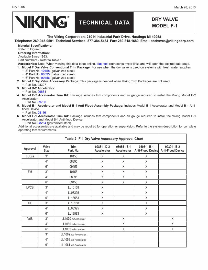
Table 2: f-1 Dry valve Accessory Approval Chart
Approval Valve Size
Trim Part. No.
09881 - D-2 Accelerator
08055 - E-1 Accelerator
08061 - B-1 Anti-Flood Device
09391 - B-2 Anti-Flood Device
cULus 3” 10158 X X X4” 08395 X X X6” 09456 X X X
FM 3” 10158 X X X4” 08395 X X X6” 09456 X X X
LPCB 3” LL10158 X X4” LL08395 X X6” LL13583 X X
CE 3” LL10158 X X4” LL08395 X X6” LL13583 X X
VdS 3” LL1070 w/Accelerator X X4” LL1060 w/Accelerator X X6” LL1062 w/Accelerator X X3” LL1069 w/o Accelerator
4” LL1059 w/o Accelerator
6” LL1061 w/o Accelerator
TECHNICAL DATA
March 28, 2013 Dry 120c
Dry vALvEmoDEL f-1
The viking Corporation, 210 N Industrial Park Drive, Hastings mI 49058Telephone: 269-945-9501 Technical Services: 877-384-5464 fax: 269-818-1680 Email: [email protected]
4. INSTALLATIoN For proper operation and approval, the valve must be trimmed in accordance with Viking Model F-1 Dry Valve Trim Charts.The Model F-1 Dry Valve must be installed in the vertical position as shown in Figure 1.Air or nitrogen supply to the dry pipe system must be clean, dry, and oil free.Automatic air supplies must be regulated, restricted, and from a continuous source. A Viking air maintenance device should be installed on each system equipped with an automatic air supply. Never exceed 60 PSI (4.1 bar) pressure in the system piping with the dry valve clapper closed.The dry valve must be installed in an area not subject to freezing temperatures or physical damage. If required, provide a valve house (enclosure) with adequate heat around the dry valve and trim. Freezing temperatures and/or excessive pressure will dam-age the dry valve member assembly. When corrosive atmospheres and/or contaminated water supplies are present, it is the owner’s responsibility to verify compat-ibility with the Model F-1 Dry Valve and associated equipment. Consider installation of the Viking accelerator and anti-flood device. An accelerator (quick opening device) is recommended on all differential dry pipe valves and is required on dry pipe systems of certain capacities. Refer to Installation Standards and Authorities Having Jurisdiction. If an accelerator is to be installed, verify that the appropriate Trim Chart is used. Prior to installing the valve, thoroughly flush the water supply piping to verify that no foreign matter is present.
A. General Installation Instructions1. Verify that necessary Trim Charts and Technical Data for the dry valve and associated equipment are available.2. Remove all plastic thread protectors from the openings of the dry valve.3. Apply a small amount of pipe-joint compound or tape to the external threads of all pipe connections required. Take care not
to allow any compound, tape, or other foreign matter inside any of the nipples or openings of the dry valve or trim compo-nents.
4. Install the Model F-1 Dry Valve and trim piping according to the current Model F-1 Dry Valve Trim Chart provided with the Trim Package and the Viking Engineering and Design Data book. The Model F-1 Dry Valve must be installed in the vertical position.
5. When installing a Viking accelerator and anti-flood device in conjunction with the Model F-1 Dry Valve, refer to the appropri-
1.2.3.4.
5.
6.
7.
8.
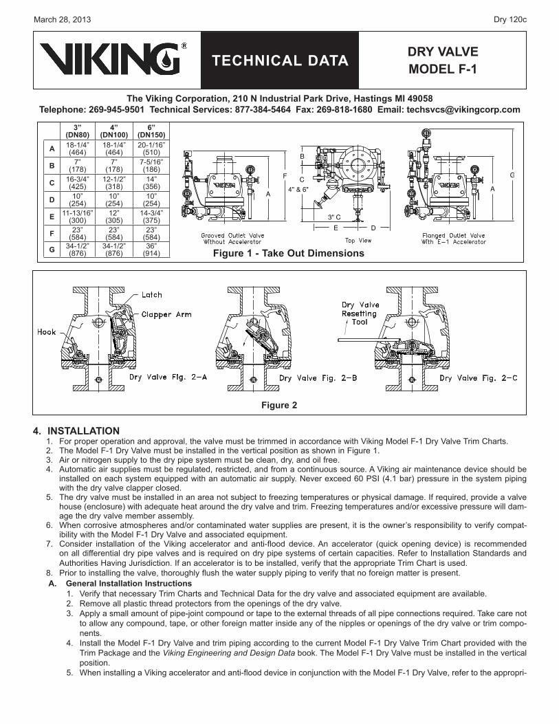
figure 2
figure 1 - Take out Dimensions
3” (DN80)
4” (DN100)
6” (DN150)
A 18-1/4” (464)
18-1/4” (464)
20-1/16” (510)
B 7” (178)
7” (178)
7-5/16” (186)
C 16-3/4” (425)
12-1/2” (318)
14” (356)
D 10” (254)
10” (254)
10” (254)
E 11-13/16” (300)
12” (305)
14-3/4” (375)
f 23” (584)
23” (584)
23” (584)
G 34-1/2” (876)
34-1/2” (876)
36” (914)
TECHNICAL DATA
March 28, 2013Dry 120d
Dry vALvEmoDEL f-1
The viking Corporation, 210 N Industrial Park Drive, Hastings mI 49058Telephone: 269-945-9501 Technical Services: 877-384-5464 fax: 269-818-1680 Email: [email protected]
ate Viking E-1 Accelerator Trim Chart provided with the Accelerator Trim Package and the Viking Engineering and Design Data book.
When a Viking accelerator is installed on the Model F-1 Dry Valve, the dry system air supply must be connected as shown on the Model E-1 Accelerator Trim Chart.The Viking external anti-flood device is required when a Viking Model E-1 Accelerator is installed on a dry valve accord-ing to the Model E-1 Accelerator Trim Chart.
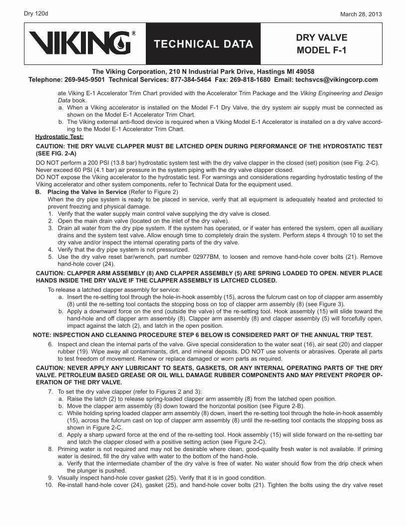
Hydrostatic Test:CAUTIoN: THE Dry vALvE CLAPPEr mUST BE LATCHED oPEN DUrING PErformANCE of THE HyDroSTATIC TEST (SEE fIG. 2-A)DO NOT perform a 200 PSI (13.8 bar) hydrostatic system test with the dry valve clapper in the closed (set) position (see Fig. 2-C).Never exceed 60 PSI (4.1 bar) air pressure in the system piping with the dry valve clapper closed.DO NOT expose the Viking accelerator to the hydrostatic test. For warnings and considerations regarding hydrostatic testing of the Viking accelerator and other system components, refer to Technical Data for the equipment used.B. Placing the valve in Service (Refer to Figure 2) When the dry pipe system is ready to be placed in service, verify that all equipment is adequately heated and protected to prevent freezing and physical damage.
1. Verify that the water supply main control valve supplying the dry valve is closed. 2. Open the main drain valve (located on the inlet of the dry valve).3. Drain all water from the dry pipe system. If the system has operated, or if water has entered the system, open all auxiliary
drains and the system test valve. Allow enough time to completely drain the system. Perform steps 4 through 10 to set the dry valve and/or inspect the internal operating parts of the dry valve.
4. Verify that the dry pipe system is not pressurized.5. Use the dry valve reset bar/wrench, part number 02977BM, to loosen and remove hand-hole cover bolts (21). Remove
hand-hole cover (24).CAUTIoN: CLAPPEr Arm ASSEmBLy (8) AND CLAPPEr ASSEmBLy (5) ArE SPrING LoADED To oPEN. NEvEr PLACE HANDS INSIDE THE Dry vALvE If THE CLAPPEr ASSEmBLy IS LATCHED CLoSED.
To release a latched clapper assembly for service: Insert the re-setting tool through the hole-in-hook assembly (15), across the fulcrum cast on top of clapper arm assembly (8) until the re-setting tool contacts the stopping boss on top of clapper arm assembly (8) (see Figure 3).Apply a downward force on the end (outside the valve) of the re-setting tool. Hook assembly (15) will slide toward the hand-hole and off clapper arm assembly (8). Clapper arm assembly (8) and clapper assembly (5) will forcefully open, impact against the latch (2), and latch in the open position.
NoTE: INSPECTIoN AND CLEANING ProCEDUrE STEP 6 BELoW IS CoNSIDErED PArT of THE ANNUAL TrIP TEST.6. Inspect and clean the internal parts of the valve. Give special consideration to the water seat (16), air seat (20) and clapper
rubber (19). Wipe away all contaminants, dirt, and mineral deposits. DO NOT use solvents or abrasives. Operate all parts to test freedom of movement. Renew or replace damaged or worn parts as required.
CAUTIoN: NEvEr APPLy ANy LUBrICANT To SEATS, GASKETS, or ANy INTErNAL oPErATING PArTS of THE Dry vALvE. PETroLEUm BASED GrEASE or oIL WILL DAmAGE rUBBEr ComPoNENTS AND mAy PrEvENT ProPEr oP-ErATIoN of THE Dry vALvE.
7. To set the dry valve clapper (refer to Figures 2 and 3):Raise the latch (2) to release spring-loaded clapper arm assembly (8) from the latched open position. Move the clapper arm assembly (8) down toward the horizontal position (see Figure 2-B).While holding spring loaded clapper arm assembly (8) down, insert the re-setting tool through the hole-in-hook assembly (15), across the fulcrum cast on top of clapper arm assembly (8) until the re-setting tool contacts the stopping boss as shown in Figure 2-C.Apply a sharp upward force at the end of the re-setting tool. Hook assembly (15) will slide forward on the re-setting bar and latch the clapper closed with a positive setting action (see Figure 2-C).
8. Priming water is not required and may not be desirable where clean, good-quality fresh water is not available. If priming water is desired, fill the dry valve with water to the bottom of the hand-hole.
Verify that the intermediate chamber of the dry valve is free of water. No water should flow from the drip check when the plunger is pushed.
9. Visually inspect hand-hole cover gasket (25). Verify that it is in good condition.10. Re-install hand-hole cover (24), gasket (25), and hand-hole cover bolts (21). Tighten the bolts using the dry valve reset
a.
b.
a.
b.
a.b.c.
d.
a.
TECHNICAL DATA
March 28, 2013 Dry 120e
Dry vALvEmoDEL f-1
The viking Corporation, 210 N Industrial Park Drive, Hastings mI 49058Telephone: 269-945-9501 Technical Services: 877-384-5464 fax: 269-818-1680 Email: [email protected]
bar/wrench, part number 02977BM.11. Close all auxiliary drains, the system test valve, and the priming water level test
valve on the dry valve trim. The main drain (located on the inlet of the dry valve) should remain open.
12. If equipped with a Viking accelerator and external anti-flood device: Close the ½” (15 mm) anti-flood isolation valve.Observe the air pressure gauge on top of the accelerator. The gauge must read zero before the accelerator will automatically reset. It may be necessary to loosen, remove, and re-install (use the appropriate wrench) the air gauge to vent trapped air pressure from the upper chamber.
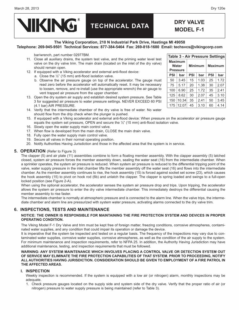
13. Open the dry system air supply and establish desired system pressure. See Table 3 for suggested air pressure to water pressure settings. NEVER EXCEED 60 PSI (4.1 bar) AIR PRESSURE.
14. Verify that the intermediate chamber of the dry valve is free of water. No water should flow from the drip check when the plunger is pushed.
15. If equipped with a Viking accelerator and external anti-flood device: When pressure on the accelerator air pressure gauge equals the system set pressure, OPEN and secure the ½” (15 mm) anti-flood isolation valve.
16. Slowly open the water supply main control valve. 17. When flow is developed from the main drain, CLOSE the main drain valve.18. Fully open the water supply main control valve. 19. Secure all valves in their normal operating position.20. Notify Authorities Having Jurisdiction and those in the affected area that the system is in service.
5. oPErATIoN (Refer to Figure 3)The clapper (5) and air plate (11) assemblies combine to form a floating member assembly. With the clapper assembly (5) latched closed, system air pressure forces the member assembly down, sealing the water seat (16) from the intermediate chamber. When a sprinkler operates, the system air pressure is reduced. When system air pressure is reduced to the differential tripping point of the valve, water supply pressure in the inlet chamber lifts the member assembly off the water seat (16) and flows into the intermediate chamber. As the member assembly continues to rise, the hook assembly (15) is forced against socket set screw (23), which causes the hook assembly (15) to pivot on hook rod (6b) and unlatch the clapper. The clapper is spring loaded and swings to a full-open locked position (see Figure 2-A). When using the optional accelerator, the accelerator senses the system air pressure drop and trips. Upon tripping, the accelerator allows the system air pressure to enter the dry valve intermediate chamber. This immediately destroys the differential causing the member assembly to rise faster.The intermediate chamber is normally at atmospheric pressure and is connected to the alarm line. When the valve trips, the interme-diate chamber and alarm line are pressurized with system water pressure, activating alarms connected to the dry valve trim.
6. INSPECTIoNS, TESTS AND mAINTENANCENoTICE: THE oWNEr IS rESPoNSIBLE for mAINTAINING THE fIrE ProTECTIoN SySTEm AND DEvICES IN ProPEr oPErATING CoNDITIoN.The Viking Model F-1 Dry Valve and trim must be kept free of foreign matter, freezing conditions, corrosive atmospheres, contami-nated water supplies, and any condition that could impair its operation or damage the device.It is imperative that the system be inspected and tested on a regular basis. The frequency of the inspections may vary due to con-taminated water supplies, corrosive water supplies, corrosive atmospheres, as well as the condition of the air supply to the system. For minimum maintenance and inspection requirements, refer to NFPA 25. In addition, the Authority Having Jurisdiction may have additional maintenance, testing, and inspection requirements that must be followed.WArNING: ANy SySTEm mAINTENANCE WHICH INvoLvES PLACING A CoNTroL vALvE or DETECTIoN SySTEm oUT of SErvICE mAy ELImINATE THE fIrE ProTECTIoN CAPABILITIES of THAT SySTEm. PrIor To ProCEEDING, NoTIfy ALL AUTHorITIES HAvING JUrISDICTIoN. CoNSIDErATIoN SHoULD BE GIvEN To EmPLoymENT of A fIrE PATroL IN THE AffECTED ArEAS.
I. INSPECTIoNWeekly inspection is recommended. If the system is equipped with a low air (or nitrogen) alarm, monthly inspections may be adequate.1. Check pressure gauges located on the supply side and system side of the dry valve. Verify that the proper ratio of air (or
nitrogen) pressure to water supply pressure is being maintained (refer to Table 3).
a.b.
Table 3 - Air Pressure Settingsmaximum
Water Pressure
minimum maximum
PSI bar PSI bar PSI bar50 3.45 15 1.03 25 1.7275 5.17 20 1.38 30 2.07
100 6.90 25 1.72 35 2.41125 8.62 30 2.07 45 3.10150 10.34 35 2.41 50 3.45175 12.07 45 3.10 60 4.14
TECHNICAL DATA
March 28, 2013Dry 120f
Dry vALvEmoDEL f-1
The viking Corporation, 210 N Industrial Park Drive, Hastings mI 49058Telephone: 269-945-9501 Technical Services: 877-384-5464 fax: 269-818-1680 Email: [email protected]
2. Verify that the intermediate chamber of the dry valve is free of water. No water should flow from the drip check when the plunger is pushed.
3. If equipped with a Viking accelerator:a. Check the air pressure gauge located on the top of the accelerator. Air pressure in the upper chamber of the accelerator
should equal the pneumatic pressure maintained in the system. NoTE: STANDArD ToLErANCE ALLoWANCE IN PrESSUrE GAUGE CALIBrATIoN mAy rESULT IN A SLIGHT vArIATIoN WHEN PrESSUrE rEADINGS from ANy TWo GAUGES ArE ComPArED. A DIffErENCE IN PrESSUrES oTHEr THAN SLIGHT vArIATIoN DUE To GAUGE CALIBrATIoN ToLErANCE mAy INDICATE mAINTENANCE IS rEqUIrED. rEfEr To TECHNICAL DATA for THE ACCELErATor USED.
b. or dry systems with Viking Accelerators installed according to the Viking Model E-1 Accelerator Trim Chart, verify that the ½” (15 mm) anti-flood isolation valve is OPEN and secured.
4. Verify that the water supply main control valve is open and all trim valves are in their normal operating position.5. Check for signs of mechanical damage and/or corrosive activity. If detected, perform maintenance as required or, if necessary,
replace the device.6. Verify that dry valve and trim are adequately heated and protected from freezing and physical damage.
II. TESTS quarterly Tests A. Water flow Alarm Test
Quarterly testing of water flow alarms is recommended and may be required by the Authority Having Jurisdiction.1. Notify the Authority Having Jurisdiction and those in the area affected by the test.
NoTE: vIKING CoNvENTIoNAL TrIm ProvIDES A CoNNECTIoN for INSTALLATIoN of A NoN-INTErrUPTIBLE PrES-SUrE SWITCH. ALArmS AND/or ELECTrIC PANELS CoNTroLLED By AN ALArm PrESSUrE SWITCH INSTALLED IN THAT CoNNECTIoN CANNoT BE INTErrUPTED. (See Dry Valve Trim Chart.)
2. Fully open the main drain (located on the base of the dry valve) to flush away any accumulation of foreign material.3. Close the main drain.4. To test the local electric alarm (if provided) and/or mechanical water motor gong (if provided), OPEN the alarm test valve
in the dry valve trim.a. Electric alarm pressure switches (if provided) should activate. b. Electric local alarms should be audible. c. The local water motor gong should be audible. d. Verify that (if provided) remote station alarm signals were received.
5. When testing is complete, close the alarm test valve.6. Verify:
a. All local alarms stop sounding and alarm panels (if provided) reset.b. All remote station alarms reset.c. All supply piping to water motor properly drains.
7. Verify that the alarm shut-off valve in the dry valve trim is OPEN, and the alarm test valve is CLOSED.8. Verify that the intermediate chamber of the dry valve is free of water. No water should flow from the drip check when the
plunger is pushed.9. Notify the Authority Having Jurisdiction and those in the affected area that testing is complete.
B. main Drain Test Quarterly performance of the Main Drain Test is recommended and may be required by Authorities Having Jurisdiction to verify integrity of the water supply.
1. Notify the Authority Having Jurisdiction and those in the area affected by the test. 2. Record pressure reading from the water supply pressure gauge.3. Verify that the intermediate chamber of the dry valve is free of water. No water should flow from the drip check when the
plunger is pushed.4. Verify that the dry pipe system is pressurized at or above the minimum pressure recommended in Table 3 for the water
supply pressure available.5. Fully OPEN the main drain located on the base of the dry valve.6. When a full flow is developed from the main drain, record the residual pressure from the water supply pressure gauge.7. When the test is complete, SLOWLY CLOSE the main drain.
TECHNICAL DATA
March 28, 2013 Dry 120g
Dry vALvEmoDEL f-1
The viking Corporation, 210 N Industrial Park Drive, Hastings mI 49058Telephone: 269-945-9501 Technical Services: 877-384-5464 fax: 269-818-1680 Email: [email protected]
8. Compare test results with previous flow information. If deterioration of the water supply is detected, take appropriate steps to restore adequate water supply.
9. Verify that normal water supply pressure and system pneumatic pressure have been restored, and that all alarm devices and valves are secured in normal operating position.
10. Notify the Authority Having Jurisdiction that the test is complete. Record and/or provide notification of test results as required by the Authority Having Jurisdiction.
C. Priming Water Level, and Low Air Alarm Test Quarterly testing is recommended to verify that water is NOT present above the Priming Level Test Valve in the dry valve trim. Quarterly testing of low air alarms is recommended.
1. Notify the Authority Having Jurisdiction and those in the area affected by the test.2. Close the water supply main control valve supplying the dry valve. 3. Open the main drain valve (located on the inlet of the dry valve).
If the dry valve being tested is equipped with a Viking accelerator and external anti-flood device installed according to Viking Model E-1 Accelerator Trim Charts, performing steps 6 or 7 of this test will cause the accelerator to operate. A burst of air from the vent in the bottom of the accelerator will indicate operation of the accelerator. However, with the water supply main control valve CLOSED and the main drain valve OPEN, operation of the accelerator should not trip the dry valve.
6. Dry valve priming water level test:a. Verify that the water supply main control valve is closed and the main drain valve is open.b. Fully open the priming level test valve in the dry valve trim to check for the presence of water. If an accelerator is
installed, this may cause the dry valve to trip. If the presence of water is detected, the system may not have been properly drained. Perform steps 1 through 3, and 11 through 15 of section 4-B PLACING DRY VALVE IN SERVICE, and repeat this dry valve priming water level test.
c. If/when no water is detected and the test is complete, continue to step 8.7. Low Air Alarm Test:
a. Verify that the water supply main control valve is closed and the main drain valve is open.b. Gradually open the priming level test valve in the trim of the dry valve to simulate operation of the dry system. Observe
and record the pressure at which the low air alarm operates.8. Close the priming level test valve.9. If the dry valve being tested is equipped with a Viking accelerator and external anti-flood device:
a. Close the ½” (15 mm) NPT anti-flood isolation valve.NoTE: AIr WILL CoNTINUE To fLoW from THE ACCELErATor AfTEr IT HAS oPErATED UNTIL STEP “B” BELoW IS PErformED.
b. Loosen (use the appropriate wrench), and remove the accelerator air gauge to release pressure from the upper chamber of the accelerator. When the accelerator re-sets, re-install the accelerator air gauge.
10. Perform steps 13 through 20 of section 4-B PLACING DRY VALVE IN SERVICE. TrIP TESTSPartial Flow Trip Tests are conducted with the water supply main control valve partially closed to minimize the amount of water enter-ing the system during the test. Performance of a Partial Flow Trip Test is recommended during warm weather at least annually except when a Full Flow Trip Test is conducted. Partial Flow Trip Tests may verify operation of equipment and devices but do not simulate operation of the system in fire conditions. Full Flow Trip Tests are conducted with the water supply main control valve fully open. The dry valve is operated by opening the system test valve to simulate the opening of a sprinkler in fire conditions. When the dry valve operates, the sprinkler piping will be flooded with water. Performance of a Full Flow Trip Test is recommended during warm weather at least once every three years. More frequent testing may be required by the Authority Having Jurisdiction.A. full flow Trip Test
1. Notify the Authority Having Jurisdiction and those in the area affected by the test.NoTE: ALArmS AND ELECTrIC PANELS CoNTroLLED By AN ALArm PrESSUrE SWITCH INSTALLED IN THE “ELEC-TrIC ALArm PANEL CoNNECTIoN” CANNoT BE INTErrUPTED (SEE Dry vALvE TrIm CArT).
2. Fully open the main drain (located on the base of the dry valve) to flush away any accumulation of foreign material.3. Close the main drain.4. Record water supply pressure and system pneumatic pressure.5. Open the remote system test valve to simulate operation of the dry system. Record:
Elapsed time from opening of the test valve to operation of the dry valve.a.
TECHNICAL DATA
March 28, 2013Dry 120h
Dry vALvEmoDEL f-1
The viking Corporation, 210 N Industrial Park Drive, Hastings mI 49058Telephone: 269-945-9501 Technical Services: 877-384-5464 fax: 269-818-1680 Email: [email protected]
System pressure when the dry valve operated.Elapsed time from opening of the test valve to development of full flow of water from the system test connection. Any other information required by the Authority Having Jurisdiction.
6. Verify that alarms operate properly.7. Allow water to flow from the system test connection until it appears clear and clean.8. When test is complete, close the water supply main control valve.9. Perform steps 1 through 20 of section 4-B PLACING DRY VALVE IN SERVICE.
10. Verify that the water supply main control valve is open, and all other valves are in their normal operating position. If equipped with an external anti-flood device, the ½” anti-flood isolation valve must be OPEN and secured.
B. Partial flow Trip Test1. Notify the Authority Having Jurisdiction and those in the area affected by the test.
NoTE: vIKING CoNvENTIoNAL TrIm ProvIDES A CoNNECTIoN for INSTALLATIoN of A NoN-INTErrUPTIBLE PrES-SUrE SWITCH. ALArmS AND ELECTrIC PANELS CoNTroLLED By AN ALArm PrESSUrE SWITCH INSTALLED IN THE “ELECTrIC ALArm PANEL CoNNECTIoN” CANNoT BE INTErrUPTED (SEE Dry vALvE TrIm CHArT).
2. Record water supply pressure and system pneumatic pressure.3. Fully open the main drain (located on the base of the dry valve) to flush away any accumulation of foreign material.4. CLOSE the water supply main control valve as far as possible while maintaining full flow from the main drain. CLOSE the
main drain.5. Open the priming level test valve to simulate operation of the system.6. Note (for records) water supply pressure and system pneumatic pressure when the dry valve operates.7. CLOSE the water supply main control valve and OPEN the main drain IMMEDIATELY when test is complete. 8. Perform steps 1 through 20 of paragraph 4-B PLACING DRY VALVE IN SERVICE. 9. Verify that the water supply main control valve is open, all other valves are in their normal operating position. If equipped
with an external anti-flood device, the ½” anti-flood isolation valve must be OPEN and secured.III. mAINTENANCE (See Figure 3)WArNING: PrIor To SErvICING INTErNAL oPErATING PArTS of THE Dry vALvE, TAKE THE foLLoWING PrECAU-TIoNS.
1. Close the water supply main control valve, placing the system out of service.2. Open the main drain located in the base of the dry valve.3. Close the air (or nitrogen) supply to the dry system piping.4. Relieve all pressure from the dry system piping. If the system has operated, open all auxiliary drains and the system test
valve to allow the system to drain completely.5. Use dry valve reset bar/wrench part number 02977BM to loosen and remove hand-hole cover bolts (21) and remove hand-dry valve reset bar/wrench part number 02977BM to loosen and remove hand-hole cover bolts (21) and remove hand-to loosen and remove hand-hole cover bolts (21) and remove hand-
hole cover (24).CAUTIoN: CLAPPEr Arm ASSEmBLy (8) AND CLAPPEr ASSEmBLy (5) IS SPrING LoADED To oPEN. NEvEr PLACE HANDS INSIDE THE Dry vALvE If THE CLAPPEr ASSEmBLy IS LATCHED CLoSED.
6. Release latched (set) clapper assembly for service:Insert the re-setting tool through the hole in hook assembly (15), across the cast fulcrum on top of clapper arm assembly (8) until the re-setting tool contacts the stopping boss on top of clapper arm assembly (8).Apply a downward force on the end (outside the valve) of the re-setting tool. Hook assembly (15) will slide toward the hand-hole and off clapper arm assembly (8). The clapper arm assembly (8) and clapper assembly (5) will forcefully open, impact against latch (2), and be trapped in the open position.
CAUTIoN: NEvEr APPLy ANy LUBrICANT To SEATS, GASKETS, or ANy INTErNAL oPErATING PArTS of THE Dry vALvE. PETroLEUm-BASED GrEASE or oIL WILL DAmAGE rUBBEr ComPoNENTS AND mAy PrEvENT ProPEr oP-ErATIoN of THE Dry vALvE.Recommended practice: When performing maintenance inside the dry valve with the clapper in the open position, cover the opening to prevent tools or parts from dropping onto the seat or into the waterway.
7. To Remove Clapper Rubber (19):Use a 9/16” wrench to remove hex-head screw (17) and rubber retainer (18).Remove the clapper rubber (19) for inspection. If the clapper rubber shows signs of wear, such as cracking, cuts, or excessively deep grooves where the rubber contacts the air or water seat, replace the rubber.
8. To Re-install Clapper Rubber (19):Place a new clapper rubber (19), over the center hub of rubber retainer (18).Position retainer (18) (with rubber in place) against clapper assembly (5) as shown in figure 2.
b.c.d.
a.
b.
a.b.
a.b.
TECHNICAL DATA
March 28, 2013 Dry 120i
Dry vALvEmoDEL f-1
The viking Corporation, 210 N Industrial Park Drive, Hastings mI 49058Telephone: 269-945-9501 Technical Services: 877-384-5464 fax: 269-818-1680 Email: [email protected]
Replace and tighten hex-head screw (17). DO NOT over-tighten. 9. To Remove Clapper Assembly (5):
While holding spring loaded clapper arm assembly (8) down, remove a retaining ring (7) from one end of the clapper rod (6a).Release the spring-loaded clapper arm assembly (8) and allow it to latch in the open position.Slide the rod (6a) out of the clapper arm assembly (8) to free the clapper assembly (5).Remove the clapper assembly (5) for inspection or replacement.
10. To Re-install Clapper Assembly (5):Reverse disassembly procedures a through d in step 9 above.
11. To Remove the Latch (2):Remove the ½” NPT pipe plug (4) (outside of the valve) to expose the latch pin (3).While holding the latch (2) with one hand, remove the latch pin (3).Remove the latch (2).
12. To Re-install the Latch (2) and Latch Pin (3), reverse disassembly procedures a through c in step 11 above.The internal member assembly of the dry valve consists of several sub-assemblies. To service these sub-assemblies, it is necessary to disassemble the dry valve.
13. To Disassemble The Dry Valve:Disconnect the trim and remove the valve from the system piping.Use dry valve reset bar/wrench, part number 02977BM, to remove hand-hole cover bolts (21) from the base (22).dry valve reset bar/wrench, part number 02977BM, to remove hand-hole cover bolts (21) from the base (22).to remove hand-hole cover bolts (21) from the base (22).Remove the housing (1) from the base (22). Member assembly components (5-15), and (17-19, 21, 25) are accessible for replacement.When inspection and/or replacement of member assembly components is complete, re-assemble the dry valve.
14. To Re-assemble the Dry Valve:Reverse disassembly procedures a through c in step 13 above.The socket-set screw (23) will need adjustment. After the valve has been completely reassembled, latch the clapper in place. With a 1/4” (6.35 mm) Allen wrench, turn the screw clockwise until it contacts the hook assembly (15). Then, turn the screw one complete turn counter-clockwise. Set the system and trip test the valve to verify proper operation of the valve.
15. To Remove the Hook Assembly (15):Remove a retaining ring (7) from one end of the hook rod (6b).Slide the rod (6b) out of the bushings in the air plate assembly (11) to free the hook assembly (15).Remove the hook assembly (15).
16. To Re-install the Hook Assembly (15):Reverse the disassembly procedures a through c in step 15 above.
17. To Remove the Clapper Arm Assembly (8) and Spring (9):Remove a retaining ring (7) from one end of the clapper arm rod (10).Slide the clapper arm rod (10) out of the bushings in the air plate assembly (11) to free the clapper arm assembly (8), taking care to retrieve the spring (9).Remove the clapper arm assembly (8), and spring (9).
18. To Re-install the Clapper Arm Assembly (8):Reverse disassembly procedures a through c in step 17 above.
19. To remove the Diaphragm (12) and Diaphragm Retainer (13):Use a 9/16” wrench to remove the hex-head screws (14).Remove the diaphragm retainer (13) and diaphragm (12) for replacement. If the diaphragm rubber shows signs of wear, such as cracking or cuts, replace the rubber diaphragm.
20. To Re-install the Diaphragm (12) and Diaphragm Retainer (13):Reverse disassembly procedures a and b in step 19 above. When re-installing the diaphragm retainer (13), cross tighten hex-head screws (14) to 20 ft. lbs. of torque for even com-pression of the diaphragm (12).When assembling the base (22) to the housing (1):i. Invert the housing (1) on a work bench so the holes for the hand-hole cover bolts (21) are facing up.ii. Position the complete member sub-assembly (5-15 & 17-19, 21, 25) with the screw holes in the diaphragm (12),
aligned with the screw holes in the inverted housing (1). Use care to align the screw holes so the hook assembly (15) properly aligns with the set screw (23).
iii. Position the base (22) over the inverted housing (1) with the member assembly (5-15 & 17-19, 21, 25). Align the screw holes so the ½” (15 mm) NPT trim connection in the base (22) aligns with the ½” (15 mm) NPT trim connec-
c.
a.
b.c.d.
a.
a.b.c.
a.b.c.
d.
a.b.
a.b.c.
a.
a.b.
c.
a.
a.b.
a.b.
c.
TECHNICAL DATA
March 28, 2013Dry 120j
Dry vALvEmoDEL f-1
The viking Corporation, 210 N Industrial Park Drive, Hastings mI 49058Telephone: 269-945-9501 Technical Services: 877-384-5464 fax: 269-818-1680 Email: [email protected]
tion in the housing (1).iv. Install the hand-hole cover bolts (21) finger tight only.v. Cross-tighten all hand-hole cover bolts (21), to 90 ft. lbs. of torque to evenly compress the diaphragm (12) and
maintain proper alignment of the member sub-assembly (5-15 & 17-19, 21, 25).
7. AvAILABILITyThe Viking Model F-1 Dry Pipe Valve is available through a network of domestic and international distributors. See the Viking Corp. Web site for closest distributor or contact The Viking Corporation.
8. GUArANTEESFor details of warranty, refer to Viking’s current list price schedule or contact Viking directly.
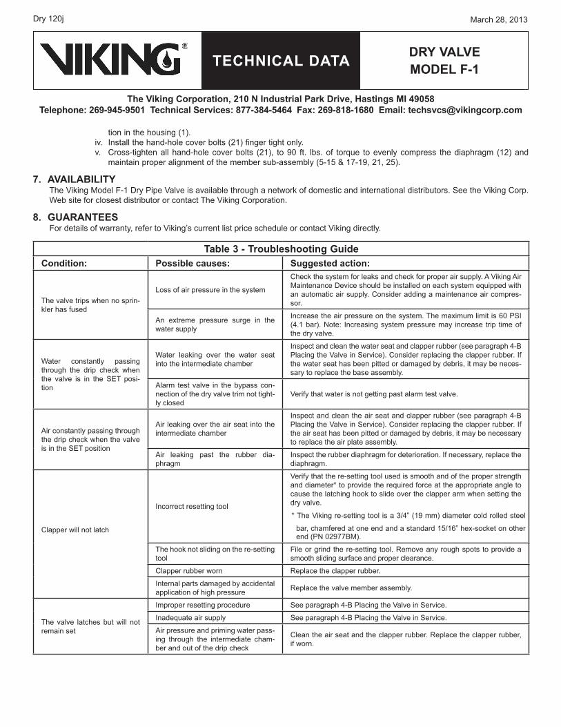
Table 3 - Troubleshooting GuideCondition: Possible causes: Suggested action:
The valve trips when no sprin-kler has fused
Loss of air pressure in the system
Check the system for leaks and check for proper air supply. A Viking Air Maintenance Device should be installed on each system equipped with an automatic air supply. Consider adding a maintenance air compres-sor.
An extreme pressure surge in the water supply
Increase the air pressure on the system. The maximum limit is 60 PSI (4.1 bar). Note: Increasing system pressure may increase trip time of the dry valve.
Water constantly passing through the drip check when the valve is in the SET posi-tion
Water leaking over the water seat into the intermediate chamber
Inspect and clean the water seat and clapper rubber (see paragraph 4-B Placing the Valve in Service). Consider replacing the clapper rubber. If the water seat has been pitted or damaged by debris, it may be neces-sary to replace the base assembly.
Alarm test valve in the bypass con-nection of the dry valve trim not tight-ly closed
Verify that water is not getting past alarm test valve.
Air constantly passing through the drip check when the valve is in the SET position
Air leaking over the air seat into the intermediate chamber
Inspect and clean the air seat and clapper rubber (see paragraph 4-B Placing the Valve in Service). Consider replacing the clapper rubber. If the air seat has been pitted or damaged by debris, it may be necessary to replace the air plate assembly.
Air leaking past the rubber dia-phragm
Inspect the rubber diaphragm for deterioration. If necessary, replace the diaphragm.
Clapper will not latch
Incorrect resetting tool
Verify that the re-setting tool used is smooth and of the proper strength and diameter* to provide the required force at the appropriate angle to cause the latching hook to slide over the clapper arm when setting the dry valve.
* The Viking re-setting tool is a 3/4” (19 mm) diameter cold rolled steel
bar, chamfered at one end and a standard 15/16” hex-socket on other end (PN 02977BM).
The hook not sliding on the re-setting tool
File or grind the re-setting tool. Remove any rough spots to provide a smooth sliding surface and proper clearance.
Clapper rubber worn Replace the clapper rubber.
Internal parts damaged by accidental application of high pressure Replace the valve member assembly.
The valve latches but will not remain set
Improper resetting procedure See paragraph 4-B Placing the Valve in Service.
Inadequate air supply See paragraph 4-B Placing the Valve in Service.
Air pressure and priming water pass-ing through the intermediate cham-ber and out of the drip check
Clean the air seat and the clapper rubber. Replace the clapper rubber, if worn.
TECHNICAL DATA
March 28, 2013 Dry 120k
Dry vALvEmoDEL f-1
The viking Corporation, 210 N Industrial Park Drive, Hastings mI 49058Telephone: 269-945-9501 Technical Services: 877-384-5464 fax: 269-818-1680 Email: [email protected]
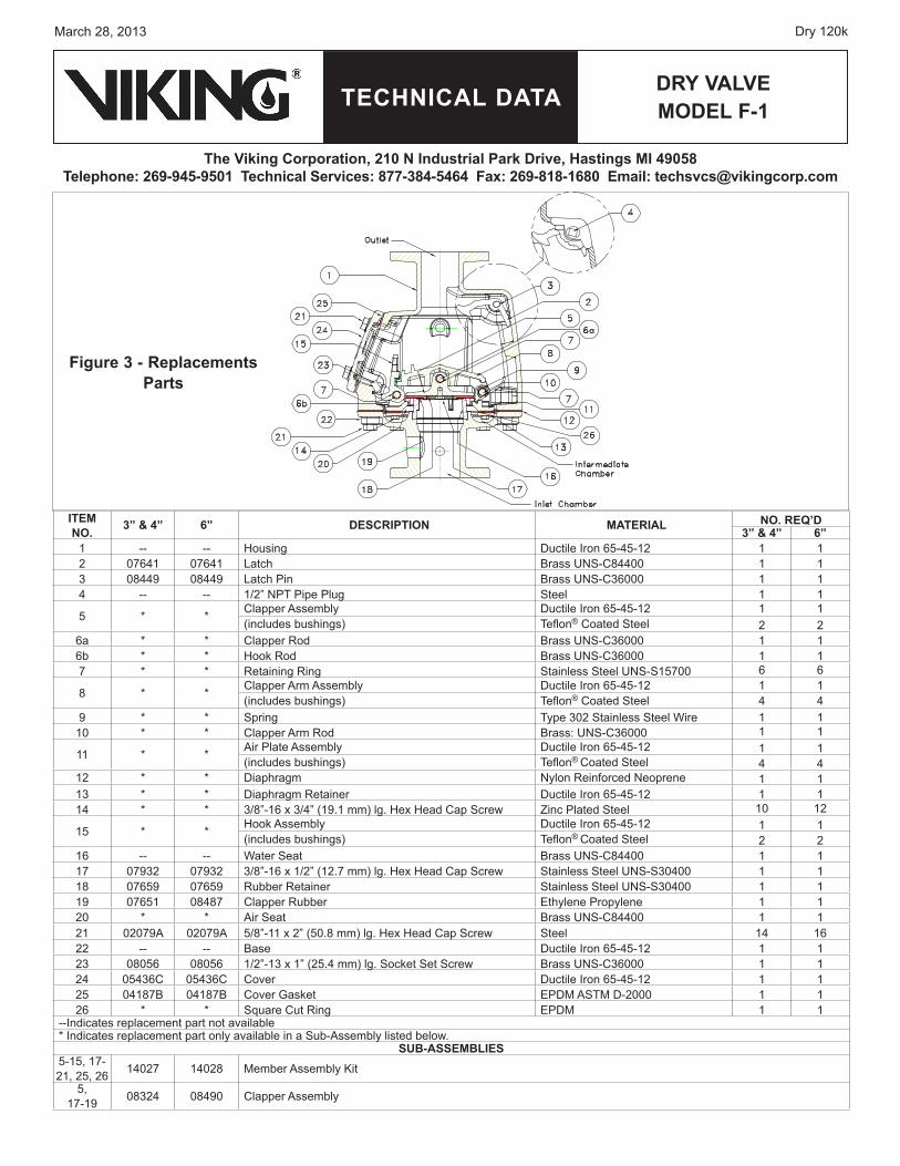
figure 3 - replacements Parts
ITEmNo. 3” & 4” 6” DESCrIPTIoN mATErIAL No. rEq’D
3” & 4” 6”1 -- -- Housing Ductile Iron 65-45-12 1 12 07641 07641 Latch Brass UNS-C84400 1 13 08449 08449 Latch Pin Brass UNS-C36000 1 14 -- -- 1/2” NPT Pipe Plug Steel 1 1
5 * * Clapper Assembly Ductile Iron 65-45-12 1 1(includes bushings) Teflon® Coated Steel 2 2
6a * * Clapper Rod Brass UNS-C36000 1 16b * * Hook Rod Brass UNS-C36000 1 17 * * Retaining Ring Stainless Steel UNS-S15700 6 6
8 * * Clapper Arm Assembly Ductile Iron 65-45-12 1 1(includes bushings) Teflon® Coated Steel 4 4
9 * * Spring Type 302 Stainless Steel Wire 1 110 * * Clapper Arm Rod Brass: UNS-C36000 1 1
11 * * Air Plate Assembly Ductile Iron 65-45-12 1 1(includes bushings) Teflon® Coated Steel 4 4
12 * * Diaphragm Nylon Reinforced Neoprene 1 113 * * Diaphragm Retainer Ductile Iron 65-45-12 1 114 * * 3/8”-16 x 3/4” (19.1 mm) lg. Hex Head Cap Screw Zinc Plated Steel 10 12
15 * * Hook Assembly Ductile Iron 65-45-12 1 1(includes bushings) Teflon® Coated Steel 2 2
16 -- -- Water Seat Brass UNS-C84400 1 117 07932 07932 3/8”-16 x 1/2” (12.7 mm) lg. Hex Head Cap Screw Stainless Steel UNS-S30400 1 118 07659 07659 Rubber Retainer Stainless Steel UNS-S30400 1 119 07651 08487 Clapper Rubber Ethylene Propylene 1 120 * * Air Seat Brass UNS-C84400 1 121 02079A 02079A 5/8”-11 x 2” (50.8 mm) lg. Hex Head Cap Screw Steel 14 1622 -- -- Base Ductile Iron 65-45-12 1 123 08056 08056 1/2”-13 x 1” (25.4 mm) lg. Socket Set Screw Brass UNS-C36000 1 124 05436C 05436C Cover Ductile Iron 65-45-12 1 125 04187B 04187B Cover Gasket EPDM ASTM D-2000 1 126 * * Square Cut Ring EPDM 1 1
--Indicates replacement part not available* Indicates replacement part only available in a Sub-Assembly listed below.
SUB-ASSEmBLIES5-15, 17- 21, 25, 26 14027 14028 Member Assembly Kit
5, 17-19 08324 08490 Clapper Assembly

THIS PAGE INTENTIONALLY
LEFT BLANK
Form No. F_070392 Revised page replaces page 120a-k, dated February 25, 2011. (Added VdS approvals)