Embed Size (px)
Citation preview

Low-voltage power distribution and control systems > Transformers >
Dry-type distribution transformers— general purpose
Contents
General Purpose Ventilated Transformers . . . . . . . . . 19 .1-2Overview . . . . . . . . . . . . . . . . . . . . . . . . . . . . . . . . . . 19 .1-2Technical Data . . . . . . . . . . . . . . . . . . . . . . . . . . . . . . 19 .1-3Dimensions . . . . . . . . . . . . . . . . . . . . . . . . . . . . . . . . 19 .1-10
General Purpose Ventilated Transformers With Integral Breakers . . . . . . . . . . . . . . . . . . . . . . . . 19 .1-11
Overview . . . . . . . . . . . . . . . . . . . . . . . . . . . . . . . . . . 19 .1-11Technical Data . . . . . . . . . . . . . . . . . . . . . . . . . . . . . . 19 .1-12Dimensions . . . . . . . . . . . . . . . . . . . . . . . . . . . . . . . . 19 .1-13
General Purpose Encapsulated Transformers . . . . . . 19 .1-14Overview . . . . . . . . . . . . . . . . . . . . . . . . . . . . . . . . . . 19 .1-14Technical Data . . . . . . . . . . . . . . . . . . . . . . . . . . . . . . 19 .1-15Dimensions . . . . . . . . . . . . . . . . . . . . . . . . . . . . . . . . 19 .1-20
Application Information . . . . . . . . . . . . . . . . . . . . . . . 19 .1-22Transformer Selection . . . . . . . . . . . . . . . . . . . . . . . . 19 .1-22Standards and Certifications . . . . . . . . . . . . . . . . . . . 19 .1-24Glossary of Transformer Terms . . . . . . . . . . . . . . . . . . 19 .1-25The Energy Policy Act of 2005 . . . . . . . . . . . . . . . . . . 19 .1-28Frequently Asked Questions About Transformers . . . 19 .1-29
More about this product
Eaton.com/transformers
Complete library of design guides
Eaton.com/designguides
Design Guide DG009001EN Effective February 2020

Overview Eaton’s family of energy-efficient ventilated transformers meets DOE 2016 efficiency requirements and federal energy efficiency laws mandated by the Energy Policy Act of 2005 and 10 CFR Part 431 (2016). Energy-efficient transformers are especially designed to have low no-load (core) losses; minimum efficiency levels have been established for these transformers when loaded at 35% of their full load capacity. Available 600 V distribution transformers installed in the United States are required to meet these energy efficiency requirements. General purpose DOE 2016 transformers, single-phase 15–100 kVA and three-phase 15–300 kVA, are manufactured in seismic certified (including OSHPD) NEMAT Type 2 enclosures with optional weathershields to make the enclosure NEMA 3R; wall mounting is available up to 112.5 kVA (1400 lb maximum weight). Coils are wound with aluminum or copper conductor and 220 °C insulation materials. The transformers are available with temperature rise options of 150 °C, 115 °C or 80 °C, NEMA ST-20 audible sound levels, and 60 or 50 Hz. Installation of energy-efficient transformers may help facilities earn points toward LEEDT certification from the U.S. Green Building Council.
Note: Three-phase general purpose transformers are available with integral circuit breakers to save installation time, footprint, and reduce arc flash incident energy at downstream panel.
Wall-mounting capability up to 1400 lb (equivalent to a typical 150 kVA three-phase ventilated transformer). Wall-mounting kits WMB04 and WMB05 are OSHPD certified
Eaton voluntarily verifies the 2016 efficiencies with UL. Customers can be sure that Eaton-manufactured transformers meet the DOE 2016 minimum required efficiencies.
Design Guide DG009001EN Effective February 2020
19 .1-2
Dry-Type Distribution TransformersGeneral Purpose
EATON www.eaton.com
General Purpose Ventilated Transformers

Technical Data
General Construction Features of General Purpose Ventilated Transformers Rated 600 V and belowEaton’s single-phase and three-phase general purpose dry-type ventilated transformers are of the two-winding type, self-cooled, and are available in a wide variety of primary and secondary voltage combinations.
Eaton’s transformers are designed, manufactured and tested in accordance with all of the latest applicable ANSI, NEMA® and IEEE® standards. All 600 V class ventilated transformers with ratings through 1000 kVA are UL® listed and bear the UL label. Open core and coil assemblies are UR labeled products.
These transformers are designed for continuous operation at rated kVA for 24 hours a day, 365 days a year, with normal life expectancy as defined in ANSI C57.96.
Efficiency validation: Eaton-manufactured transformers in compliance with 10 CFR Part 431 (2016), “DOE 2016 efficient” bear the UL Energy Efficiency Verification Mark to confirm that the transformer meets the energy efficiency requirements set forth in federal law 10 CFR Part 431.
Insulation SystemThe design life of transformers having different insulation systems is the same; the lower temperature systems are designed for the same life as the higher temperature systems.
Eaton ventilated transformers, regardless of their temperature rise, are manufactured using a 220 °C insulation system. Required performance is obtained without exceeding the insulation system rating at rated temperature rise in a 40 °C maximum ambient, with an average ambient temperature of 30 °C over a 24-hour period.
Transformers manufactured with 220C insulation system meet the requirements of NEC 450.21(b) Exception No.2. It is not necessary to install them in a special, fire-resistant room.
All insulation materials used are flame-retardant and do not support combustion as defined in ASTM Standard Test Method D635.
Core and Coil AssembliesThe transformer core is constructed using high-grade, non-aging, silicon steel with high magnetic permeability, and low hysteresis and eddy current losses. Maximum magnetic flux densities are substantially below the saturation point. The transformer core volume allows for efficient transformer operation at 10% above the nominal tap voltage. The core laminations are tightly clamped and compressed. Coils are wound of electrical grade aluminum or copper, and are of continuous wound construction. The BIL (basic impulse level) for all 600 V-class windings is 10 kV. The core and coil assembly is installed on neoprene vibration-absorbing pads.
Ventilated transformers with wye-connected secondaries have the neutral brought out to a separate XO terminal or busbar.
The core and coil assembly is grounded to the transformer enclosure by means of a visible flexible copper ground strap. The copper ground strap is sized per the NEC to be a grounding conductor.
Eaton three-phase DOE 2016 efficient transformers are provided with a bonding ground bar attached to the bottom panel for compliance with NEC 450.10(A).
Transformer core and coil covered with a fungus-resistant varnish to seal out moisture and other contaminants, and prevent the growth of fungus.
Electrostatic ShieldingThere are no industry standards for electrostatic shield performance. Eaton-manufactured transformers have been tested by an independent laboratory to meet the following attenuation levels:
When tested per MIL-Std-220A, Method of Insertion Loss Measurement, with matched impedance no load technique:
1. Common mode noise attenuation: Minus 80 dBA minimum at 0.1 kHz to 1.5 kHz; minus 55 dBA minimum at 1.51 kHz to 100 kHz.
2. Normal mode (Transverse mode) noise attenuation: Minus 35 dBA minimum at 1.5 kHz to 10 kHz.
Primary to Secondary Capacitance of 24.74–18.06 picofarads on the range 100–20 kHz.
TapsPrimary taps are available on most Eaton ventilated transformers to allow compensation for source voltage variations.
Winding TerminationsPrimary and secondary windings are terminated in the wiring compartment. Encapsulated units have copper leads or stabs brought out for connections. Ventilated transformers have leads brought out to aluminum or copper pads that are pre-drilled to accept Cu/Al lugs. Aluminum-wound transformers have aluminum pads; copper-wound transformers have copper pads. Lugs are not supplied with Eaton transformers; however, lug kits are available as a field-installed accessory. Eaton recommends external cables be rated 90 °C (sized at 75 °C ampacity) for encapsulated designs and rated 75 °C for ventilated designs.
Series-Multiple WindingsSeries-multiple windings consist of two similar coils in each winding that can be connected in series or parallel (multiple). Transformers with series-multiple windings are designated with an “x” or a “/” between the voltage ratings, such as voltages of “240 x 480” or “120/240.” If the series-multiple winding is designated by an “x,” the winding can be connected only in series or parallel. With a “/” designation, a mid-point also becomes available in addition to the series or parallel connection. As an example, a 240 x 480 winding can be connected for either 240 (parallel) or 480 (series). A 120/240 winding can be connected for either 120 (parallel) or 240 (series), or 240 with a 120 mid-point.
Design Guide DG009001EN Effective February 2020
19 .1-3
Dry-Type Distribution TransformersGeneral PurposeGeneral Purpose Ventilated Transformers
EATON www.eaton.com
EnclosuresThe transformer enclosure is made of heavy-gauge steel and is finished using a continuous process of degreasing, cleaning and phosphatizing, followed by electrostatic deposition of a thermo-setting polyester powder coating and subsequent baking. The coating color is ANSI 61 and is UL recognized for outdoor use. In compliance with NEMA ST-20, Eaton’s ventilated transformers are designed such that the maximum temperature on the top of the enclosure does not exceed 50 °C rise above the ambient temperature.
For ventilated transformers, the enclosure construction is ventilated, drip-proof, NEMA 2, with lifting provisions.
All ventilation openings are protected against falling dirt. Proper installation of weathershields on ventilated transformers makes the enclosure NEMA 3R rated and suitable for outdoor use.
To ensure proper ventilation and cooling of the transformer, follow manufacturer’s recommended clear ances around ventilation openings.
Installation ClearancesEaton’s transformers should be installed with a minimum clearance around the transformer enclosure to prevent accidental contact with flammable or combustible materials. The minimum required clearance from the back panel varies by transformer design. Many small kVA ventilated transformers (150 kVA and smaller) require just 2 inches of clearance, while larger kVA transformers require 6-inch clearance or more. Minimum installation clear ances are stated on the nameplate of all transformers.
The NEC requires a minimum of 36 inches clearance in front of the transformer for safe installation and maintenance. Care should be taken to avoid restricting the airflow through the bottom of the transformer.
Transformers should be located in areas not accessible to the public.
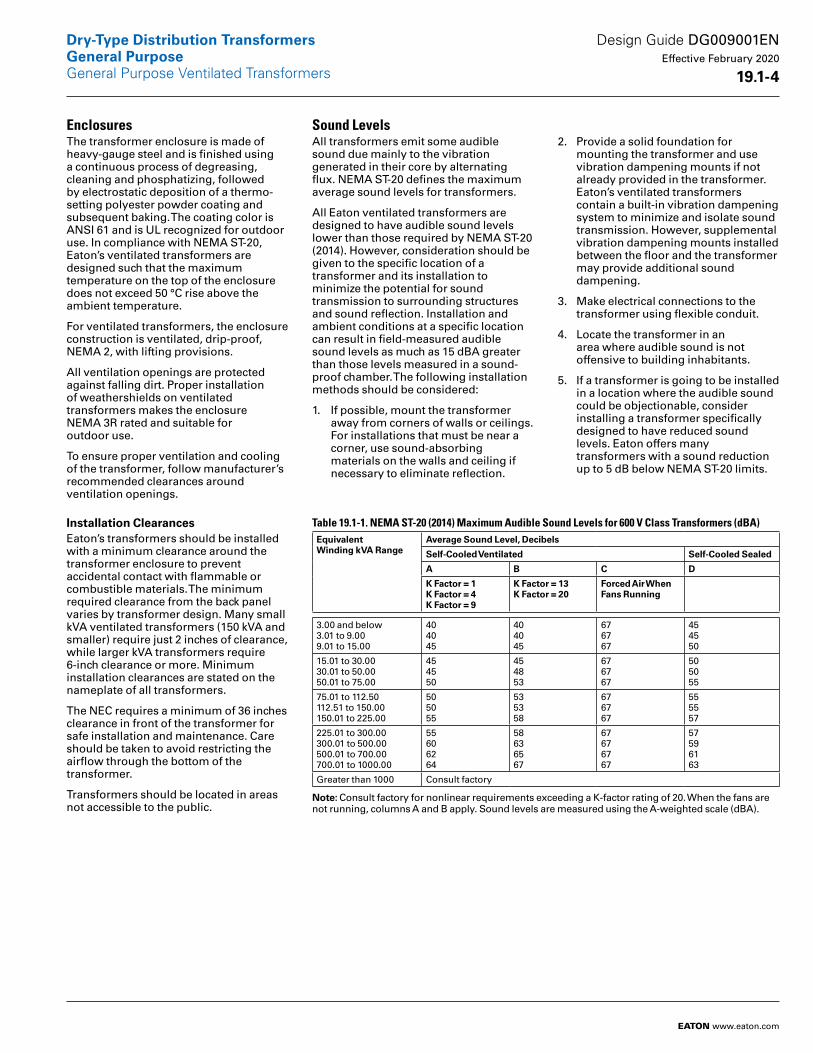
Sound LevelsAll transformers emit some audible sound due mainly to the vibration generated in their core by alternating flux. NEMA ST-20 defines the maximum average sound levels for transformers.
All Eaton ventilated transformers are designed to have audible sound levels lower than those required by NEMA ST-20 (2014). However, consideration should be given to the specific location of a transformer and its installation to minimize the potential for sound transmission to surrounding structures and sound reflection. Installation and ambient conditions at a specific location can result in field-measured audible sound levels as much as 15 dBA greater than those levels measured in a sound-proof chamber. The following installation methods should be considered:
1. If possible, mount the transformer away from corners of walls or ceilings. For installations that must be near a corner, use sound-absorbing materials on the walls and ceiling if necessary to eliminate reflection.
2. Provide a solid foundation for mounting the transformer and use vibration dampening mounts if not already provided in the transformer. Eaton’s ventilated transformers contain a built-in vibration dampening system to minimize and isolate sound transmission. However, supplemental vibration dampening mounts installed between the floor and the transformer may provide additional sound dampening.
3. Make electrical connections to the transformer using flexible conduit.
4. Locate the transformer in an area where audible sound is not offensive to building inhabitants.
5. If a transformer is going to be installed in a location where the audible sound could be objectionable, consider installing a transformer specifically designed to have reduced sound levels. Eaton offers many transformers with a sound reduction up to 5 dB below NEMA ST-20 limits.
Table 19.1-1. NEMA ST-20 (2014) Maximum Audible Sound Levels for 600 V Class Transformers (dBA)Equivalent Winding kVA Range
Average Sound Level, Decibels
Self-Cooled Ventilated Self-Cooled Sealed
A B C D
K Factor = 1K Factor = 4K Factor = 9
K Factor = 13K Factor = 20
Forced Air When Fans Running
3.00 and below3.01 to 9.009.01 to 15.00
404045
404045
676767
454550
15.01 to 30.0030.01 to 50.0050.01 to 75.00
454550
454853
676767
505055
75.01 to 112.50112.51 to 150.00150.01 to 225.00
505055
535358
676767
555557
225.01 to 300.00300.01 to 500.00500.01 to 700.00700.01 to 1000.00
55606264
58636567
67676767
57596163
Greater than 1000 Consult factory
Note: Consult factory for nonlinear requirements exceeding a K-factor rating of 20. When the fans are not running, columns A and B apply. Sound levels are measured using the A-weighted scale (dBA).
Design Guide DG009001EN Effective February 2020
19 .1-4
Dry-Type Distribution TransformersGeneral PurposeGeneral Purpose Ventilated Transformers
EATON www.eaton.com
Applicable Standards600 V-class ventilated transformers are manufactured per the following standards:
■ UL 1561■ NEMA ST-20■ ANSI C57.12.01■ IEC 60726 for CE-marked ventilated models
Standard Production TestsThe following production tests are performed as standard on all Eaton transformers, prior to shipment:
1. Ratio tests at the rated voltage connection and at all tap connections.
2. Polarity and phase relation tests on the rated voltage connection.
3. Applied potential tests.
4. Induced potential tests.
5. No-load and excitation current at rated voltage on the rated voltage connection.
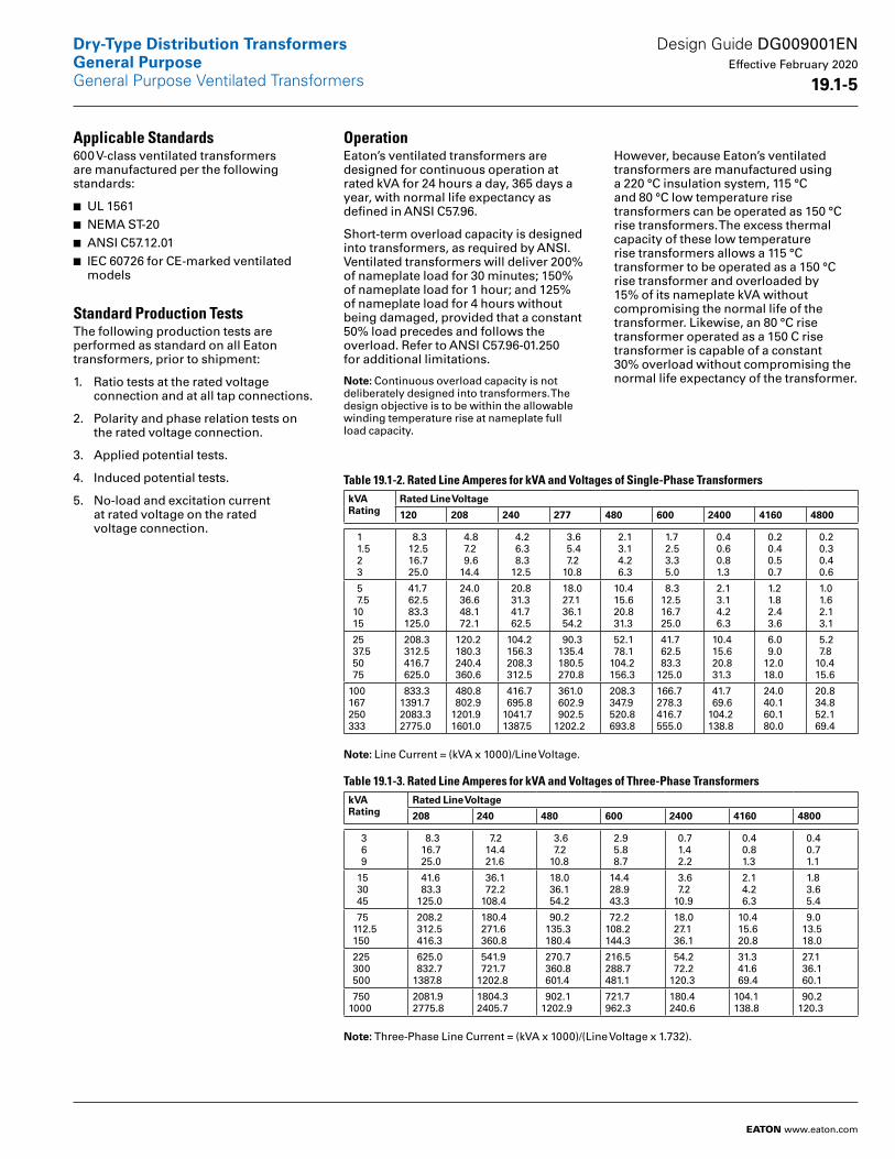
OperationEaton’s ventilated transformers are designed for continuous operation at rated kVA for 24 hours a day, 365 days a year, with normal life expectancy as defined in ANSI C57.96.
Short-term overload capacity is designed into transformers, as required by ANSI. Ventilated transformers will deliver 200% of nameplate load for 30 minutes; 150% of nameplate load for 1 hour; and 125% of nameplate load for 4 hours without being damaged, provided that a constant 50% load precedes and follows the overload. Refer to ANSI C57.96-01.250 for additional limitations.
Note: Continuous overload capacity is not deliberately designed into transformers. The design objective is to be within the allowable winding temperature rise at nameplate full load capacity.
However, because Eaton’s ventilated transformers are manufactured using a 220 °C insulation system, 115 °C and 80 °C low temperature rise transform ers can be operated as 150 °C rise transformers. The excess thermal capacity of these low temperature rise transformers allows a 115 °C trans former to be operated as a 150 °C rise transformer and overloaded by 15% of its nameplate kVA without compromis ing the normal life of the transformer. Likewise, an 80 °C rise transformer operated as a 150 C rise transformer is capable of a constant 30% overload without compromising the normal life expectancy of the transformer.
Table 19.1-2. Rated Line Amperes for kVA and Voltages of Single-Phase TransformerskVARating
Rated Line Voltage
120 208 240 277 480 600 2400 4160 4800
1 1.5 2 3
8.3 12.5 16.7 25.0
4.8 7.2 9.6 14.4
4.2 6.3 8.3 12.5
3.6 5.4 7.2 10.8
2.1 3.1 4.2 6.3
1.7 2.5 3.3 5.0
0.4 0.6 0.8 1.3
0.2 0.4 0.5 0.7
0.2 0.3 0.4 0.6
5 7.5 10 15
41.7 62.5 83.3 125.0
24.0 36.6 48.1 72.1
20.8 31.3 41.7 62.5
18.0 27.1 36.1 54.2
10.4 15.6 20.8 31.3
8.3 12.5 16.7 25.0
2.1 3.1 4.2 6.3
1.2 1.8 2.4 3.6
1.0 1.6 2.1 3.1
25 37.5 50 75
208.3 312.5 416.7 625.0
120.2 180.3 240.4 360.6
104.2 156.3 208.3 312.5
90.3 135.4 180.5 270.8
52.1 78.1 104.2 156.3
41.7 62.5 83.3125.0
10.4 15.6 20.8 31.3
6.0 9.0 12.0 18.0
5.2 7.8 10.4 15.6
100167250333
833.31391.72083.32775.0
480.8 802.91201.91601.0
416.7 695.81041.71387.5
361.0 602.9 902.51202.2
208.3 347.9 520.8 693.8
166.7278.3416.7555.0
41.7 69.6104.2138.8
24.0 40.1 60.1 80.0
20.8 34.8 52.1 69.4
Note: Line Current = (kVA x 1000)/Line Voltage.
Table 19.1-3. Rated Line Amperes for kVA and Voltages of Three-Phase TransformerskVARating
Rated Line Voltage
208 240 480 600 2400 4160 4800
3 6 9
8.3 16.7 25.0
7.2 14.4 21.6
3.6 7.2 10.8
2.9 5.8 8.7
0.7 1.4 2.2
0.4 0.8 1.3
0.4 0.7 1.1
15 30 45
41.6 83.3 125.0
36.1 72.2 108.4
18.0 36.1 54.2
14.4 28.9 43.3
3.6 7.2 10.9
2.1 4.2 6.3
1.8 3.6 5.4
75 112.5 150
208.2 312.5 416.3
180.4 271.6 360.8
90.2 135.3 180.4
72.2108.2144.3
18.0 27.1 36.1
10.4 15.6 20.8
9.0 13.5 18.0
225 300 500
625.0 832.71387.8
541.9 721.71202.8
270.7 360.8 601.4
216.5288.7481.1
54.2 72.2120.3
31.3 41.6 69.4
27.1 36.1 60.1
7501000
2081.92775.8
1804.32405.7
902.11202.9
721.7962.3
180.4240.6
104.1138.8
90.2120.3
Note: Three-Phase Line Current = (kVA x 1000)/(Line Voltage x 1.732).
Design Guide DG009001EN Effective February 2020
19 .1-5
Dry-Type Distribution TransformersGeneral PurposeGeneral Purpose Ventilated Transformers
EATON www.eaton.com
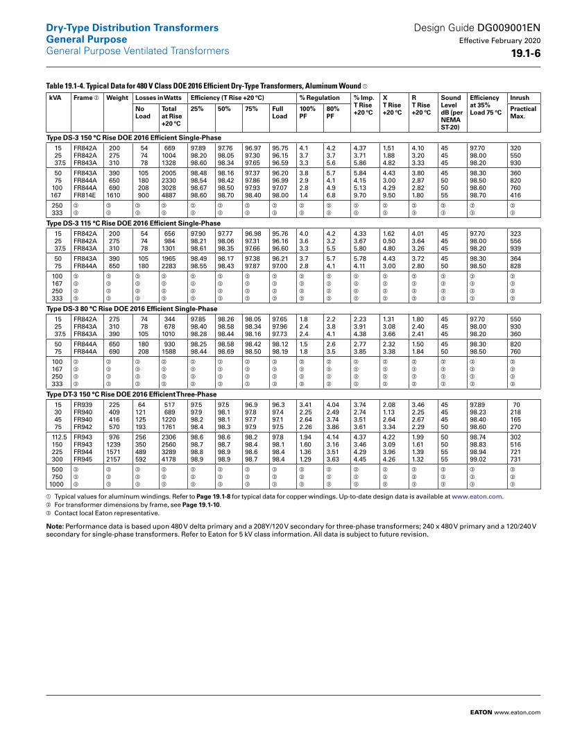
Table 19.1-4. Typical Data for 480 V Class DOE 2016 Efficient Dry-Type Transformers, Aluminum Wound a kVA Frame b Weight Losses in Watts Efficiency (T Rise +20 ºC) % Regulation % Imp .
T Rise +20 ºC
X T Rise +20 ºC
R T Rise +20 ºC
SoundLevel dB (per NEMA ST-20)
Efficiency at 35% Load 75 ºC
Inrush
No Load
Total at Rise +20 ºC
25% 50% 75% Full Load
100% PF
80% PF
PracticalMax .
Type DS-3 150 °C Rise DOE 2016 Efficient Single-Phase 15 25 37.5
FR842AFR842AFR843A
200 275 310
54 74 78
66910041328
97.8998.2098.60
97.7698.0598.34
96.9797.3097.65
95.7596.1596.59
4.13.73.3
4.23.75.6
4.373.715.86
1.511.884.82
4.103.203.33
454545
97.7098.0098.20
320550930
50 75 100 167
FR843AFR844AFR844AFR814E
390 650 6901610
105 180 208 900
2005233030284887
98.4898.5498.6798.60
98.1698.4298.5098.70
97.3797.8697.9398.40
96.2096.9997.0798.00
3.82.92.81.4
5.74.14.96.8
5.844.155.139.70
4.433.004.299.50
3.802.872.821.80
45505055
98.3098.5098.6098.70
360820760416
250 333
c
c
c
c
c
c
c
c
c
c
c
c
c
c
c
c
c
c
c
c
c
c
c
c
c
c
c
c
c
c
c
c
Type DS-3 115 °C Rise DOE 2016 Efficient Single-Phase 15 25 37.5
FR842AFR842AFR843A
200 275 310
54 74 78
656 9841301
97.9098.2198.61
97.7798.0698.35
96.9897.3197.66
95.7696.1696.60
4.03.63.3
4.23.25.5
4.333.675.80
1.620.504.80
4.013.643.26
454545
97.7098.0098.20
323556939
50 75
FR843AFR844A
390 650
105 180
19652283
98.4998.55
98.1798.43
97.3897.87
96.2197.00
3.72.8
5.74.1
5.784.11
4.433.00
3.722.80
4550
98.3098.50
364828
100 167 250 333
c
c
c
c
c
c
c
c
c
c
c
c
c
c
c
c
c
c
c
c
c
c
c
c
c
c
c
c
c
c
c
c
c
c
c
c
c
c
c
c
c
c
c
c
c
c
c
c
c
c
c
c
c
c
c
c
c
c
c
c
c
c
c
c
Type DS-3 80 °C Rise DOE 2016 Efficient Single-Phase 15 25 37.5
FR842AFR843AFR843A
275 310 390
74 78 105
344 6781010
97.8598.4098.28
98.2698.5898.44
98.0598.3498.16
97.6597.9697.73
1.82.42.4
2.23.84.1
2.233.914.38
1.313.083.66
1.802.402.41
454545
97.7098.0098.20
550930360
50 75
FR844AFR844A
650 690
180 208
9301588
98.2598.44
98.5898.69
98.4298.50
98.1298.19
1.51.8
2.63.5
2.773.85
2.323.38
1.501.84
4550
98.3098.50
820760
100 167 250 333
c
c
c
c
c
c
c
c
c
c
c
c
c
c
c
c
c
c
c
c
c
c
c
c
c
c
c
c
c
c
c
c
c
c
c
c
c
c
c
c
c
c
c
c
c
c
c
c
c
c
c
c
c
c
c
c
c
c
c
c
c
c
c
c
Type DT-3 150 °C Rise DOE 2016 Efficient Three-Phase 15 30 45 75
FR939FR940FR940FR942
225 409 416 570
64121125193
517 68912201761
97.597.998.298.4
97.598.198.198.3
96.997.897.797.9
96.397.497.197.5
3.412.252.642.26
4.042.493.743.86
3.742.743.513.61
2.081.132.643.34
3.462.252.672.29
45454550
97.8998.2398.4098.60
70218165270
112.5 150 225 300
FR943FR943FR944FR945
976123915712157
256350489592
2306256032894178
98.698.798.898.9
98.698.798.998.9
98.298.498.698.7
97.898.198.498.4
1.941.601.361.29
4.143.163.513.63
4.373.464.294.45
4.223.093.964.26
1.991.611.391.32
50505555
98.7498.8398.9499.02
302516721731
500 7501000
c
c
c
c
c
c
c
c
c
c
c
c
c
c
c
c
c
c
c
c
c
c
c
c
c
c
c
c
c
c
c
c
c
c
c
c
c
c
c
c
c
c
c
c
c
c
c
c
a Typical values for aluminum windings. Refer to Page 19 .1-8 for typical data for copper windings. Up-to-date design data is available at www.eaton.com.b For transformer dimensions by frame, see Page 19 .1-10.c Contact local Eaton representative.
Note: Performance data is based upon 480 V delta primary and a 208Y/120 V secondary for three-phase transformers; 240 x 480 V primary and a 120/240 V secondary for single-phase transformers. Refer to Eaton for 5 kV class information. All data is subject to future revision.
Design Guide DG009001EN Effective February 2020
19 .1-6
Dry-Type Distribution TransformersGeneral PurposeGeneral Purpose Ventilated Transformers
EATON www.eaton.com

Table 19.1-14. Typical Data for 480 V Class DOE 2016 Efficient Dry-Type Transformers, Aluminum Wound a (Continued)kVA Frame b Weight Losses in Watts Efficiency (T Rise +20 ºC) % Regulation % Imp .
T Rise +20 ºC
X T Rise +20 ºC
R T Rise +20 ºC
SoundLevel dB (per NEMA ST-20)
Efficiency at 35% Load 75 ºC
Inrush
No Load
Total at Rise +20 ºC
25% 50% 75% Full Load
100% PF
80% PF
PracticalMax .
Type DT-3 115 °C Rise DOE 2016 Efficient Three-Phase 15 30 45 75
FR939FR940FR940FR942
231 399 429 605
64121125193
472 58611561655
97.697.998.398.4
97.698.398.298.4
97.298.097.898.0
96.697.797.297.6
3.101.912.492.11
3.782.354.104.07
3.542.213.813.82
2.081.373.443.90
3.141.902.522.14
45454550
97.8998.2398.4098.60
70196146244
112.5 150 225 300
FR943FR943FR944FR945
982125316072193
256350489592
2236240030923874
98.698.798.898.9
98.698.898.999.0
98.298.598.798.8
97.898.298.498.5
1.861.481.261.18
4.433.373.893.77
4.533.975.304.52
4.813.594.734.65
1.891.491.281.21
50505555
98.7498.8398.9499.02
265447610675
500 7501000
c
c
c
c
c
c
c
c
c
c
c
c
c
c
c
c
c
c
c
c
c
c
c
c
c
c
c
c
c
c
c
c
c
c
c
c
c
c
c
c
c
c
c
c
c
c
c
c
Type DT-3 80 °C Rise DOE 2016 Efficient Three-Phase 15 30 45 75
FR939FR940FR942FR943
237 436 570 970
65125193256
508 452 531 865
98.098.098.098.4
97.998.498.698.8
97.498.398.698.7
96.898.198.498.5
3.631.451.121.06
3.812.492.312.76
3.812.503.613.11
2.401.762.012.81
2.961.781.371.32
45455050
97.8998.2398.4098.60
70165270302
112.5 150 225
FR943FR944FR945
127416282157
350489592
122012441999
98.598.598.7
98.998.999.0
98.899.099.0
98.698.998.9
0.990.740.80
2.372.342.73
2.622.903.35
2.312.643.20
1.210.930.99
505555
98.7498.8398.94
516721731
300 500 7501000
c
c
c
c
c
c
c
c
c
c
c
c
c
c
c
c
c
c
c
c
c
c
c
c
c
c
c
c
c
c
c
c
c
c
c
c
c
c
c
c
c
c
c
c
c
c
c
c
c
c
c
c
c
c
c
c
c
c
c
c
c
c
c
c
a Typical values for aluminum windings. Refer to Page 19 .1-8 for typical data for copper windings. Up-to-date design data is available at www.eaton.com.b For transformer dimensions by frame, see Page 19 .1-10.c Contact local Eaton representative.
Note: Performance data is based upon 480 V delta primary and a 208Y/120 V secondary for three-phase transformers; 240 x 480 V primary and a 120/240 V secondary for single-phase transformers. Refer to Eaton for 5 kV class information. All data is subject to future revision.
Design Guide DG009001EN Effective February 2020
19 .1-7
Dry-Type Distribution TransformersGeneral PurposeGeneral Purpose Ventilated Transformers
EATON www.eaton.com
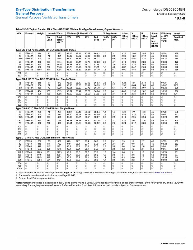
Table 19.1-5. Typical Data for 480 V Class DOE 2016 Efficient Dry-Type Transformers, Copper Wound a kVA Frame b Weight Losses in Watts Efficiency (T Rise +20 ºC) % Regulation % Imp .
T Rise +20 ºC
X T Rise +20 ºC
R T Rise +20 ºC
SoundLevel dB(per NEMA ST-20)
Efficiency at 35% Load 75 ºC
Inrush
No Load
Total at Rise +20 ºC
25% 50% 75% Full Load
100% PF
80% PF
PracticalMax .
Type DS-3 150 °C Rise DOE 2016 Efficient Single-Phase 15 25 37.5
FR842AFR842AFR843A
216 295 440
54 74 78
480 9611254
98.0698.3298.60
98.1698.3298.36
97.6897.8097.71
96.9296.9896.77
2.72.63.1
3.22.95.5
3.262.985.83
1.601.224.91
2.842.723.14
454545
97.7098.0098.20
335 267 588
50 75 100 167
FR843AFR844AFR844AFR814E
450 890 9501665
105180208570
1544212928433094
98.6098.5898.7898.70
98.4198.5298.7398.80
97.7898.0298.3398.60
96.8397.2597.7198.30
2.82.11.81.5
4.13.54.26.3
4.133.474.329.00
2.962.303.428.80
2.882.602.641.50
45505055
98.3098.5098.6098.70
472 919 828 955
250 333
c
c
c
c
c
c
c
c
c
c
c
c
c
c
c
c
c
c
c
c
c
c
c
c
c
c
c
c
c
c
c
c
Type DS-3 115 °C Rise DOE 2016 Efficient Single-Phase 15 25 37.5
FR842AFR842AFR843A
218 300 450
54 74 78
470 9421229
98.0798.3398.61
98.1798.3398.37
97.6997.8197.72
96.9396.9996.78
2.83.53.1
3.22.75.4
3.232.955.77
1.650.644.89
2.782.883.07
454545
97.7098.0098.20
2471162 338
50 75
FR843AFR844A
464 900
105180
15132086
98.6198.59
98.4298.53
97.7998.03
96.8497.26
2.82.5
4.13.4
4.093.44
2.962.31
2.822.54
4550
98.3098.50
7801041
100 167 250 333
c
c
c
c
c
c
c
c
c
c
c
c
c
c
c
c
c
c
c
c
c
c
c
c
c
c
c
c
c
c
c
c
c
c
c
c
c
c
c
c
c
c
c
c
c
c
c
c
c
c
c
c
c
c
c
c
c
c
c
c
c
c
c
c
Type DS-3 80 °C Rise DOE 2016 Efficient Single-Phase 15 25 37.5
FR842AFR843AFR843A
295 440 450
74 78105
284 373 456
97.9298.4098.35
98.4398.5998.61
98.3298.3698.41
98.0498.0098.07
1.41.20.9
1.83.22.5
1.793.893.10
1.113.702.95
1.401.180.94
454545
97.7098.0098.20
588 472 919
50 75
FR844AFR844A
890 950
180208
755 856
98.2898.51
98.6598.84
98.5298.73
98.2698.52
1.20.9
2.12.6
2.313.24
2.013.12
1.150.86
4550
98.3098.50
828 955
100 167 250 333
c
c
c
c
c
c
c
c
c
c
c
c
c
c
c
c
c
c
c
c
c
c
c
c
c
c
c
c
c
c
c
c
c
c
c
c
c
c
c
c
c
c
c
c
c
c
c
c
c
c
c
c
c
c
c
c
c
c
c
c
c
c
c
c
Type DT-3 150 °C Rise DOE 2016 Efficient Three-Phase 15 30 45 75
FR939FR940FR940FR942
250 415 478 676
73114118206
401 73212711615
97.597.998.398.4
97.798.198.198.4
97.497.797.698.1
96.997.397.097.6
2.62.42.82.1
3.12.43.82.8
2.92.63.43.2
1.60.82.61.9
2.72.42.82.1
45454550
97.8998.2398.498.6
109 262 181 399
112.5 150 225 300
FR943FR943FR944FR945
1263141017452354
251350418561
2223235141034491
98.698.798.899.0
98.698.898.798.9
98.398.598.498.7
97.998.298.098.3
1.91.51.71.4
3.42.83.83.0
3.63.44.33.5
3.12.64.03.2
1.91.51.31.4
50505555
98.7498.8398.9499.02
351 597 540 858
500 7501000
c
c
c
c
c
c
c
c
c
c
c
c
c
c
c
c
c
c
c
c
c
c
c
c
c
c
c
c
c
c
c
c
c
c
c
c
c
c
c
c
c
c
c
c
c
c
c
c
a Typical values for copper windings. Refer to Page 19 .1-6 for typical data for aluminum windings. Up-to-date design data is available at www.eaton.com.b For transformer dimensions by frame, see Page 19 .1-10.c Contact local Eaton representative.
Note: Performance data is based upon 480 V delta primary and a 208Y/120 V secondary for three-phase transformers; 240 x 480 V primary and a 120/240 V secondary for single-phase transformers. Refer to Eaton for 5 kV class information. All data is subject to future revision.
Design Guide DG009001EN Effective February 2020
19 .1-8
Dry-Type Distribution TransformersGeneral PurposeGeneral Purpose Ventilated Transformers
EATON www.eaton.com
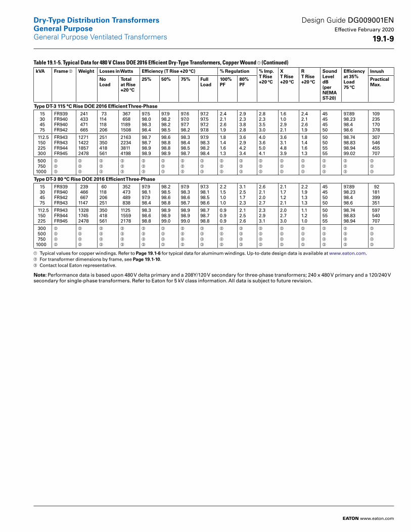
Table 19.1-5. Typical Data for 480 V Class DOE 2016 Efficient Dry-Type Transformers, Copper Wound a (Continued)kVA Frame b Weight Losses in Watts Efficiency (T Rise +20 ºC) % Regulation % Imp .
T Rise +20 ºC
X T Rise +20 ºC
R T Rise +20 ºC
SoundLevel dB(per NEMA ST-20)
Efficiency at 35% Load 75 ºC
Inrush
No Load
Total at Rise +20 ºC
25% 50% 75% Full Load
100% PF
80% PF
PracticalMax .
Type DT-3 115 °C Rise DOE 2016 Efficient Three-Phase 15 30 45 75
FR939FR940FR940FR942
241 433 471 665
73114118206
367 65811891508
97.598.098.398.4
97.998.298.298.5
97.697.097.798.2
97.297.597.297.8
2.42.12.61.9
2.92.33.82.8
2.82.33.53.0
1.61.02.92.1
2.42.12.61.9
45454550
97.8998.2398.498.6
109 235 170 378
112.5 150 225 300
FR943FR943FR944FR945
1271142218572478
251350418561
2163223438114198
98.798.798.998.9
98.698.898.898.9
98.398.498.598.7
97.998.398.298.4
1.81.41.61.3
3.62.94.23.4
4.03.65.04.1
3.63.14.83.9
1.81.41.61.3
50505555
98.7498.8398.9499.02
307 546 455 707
500 7501000
c
c
c
c
c
c
c
c
c
c
c
c
c
c
c
c
c
c
c
c
c
c
c
c
c
c
c
c
c
c
c
c
c
c
c
c
c
c
c
c
c
c
c
c
c
c
c
c
Type DT-3 80 °C Rise DOE 2016 Efficient Three-Phase 15 30 45 75
FR939FR940FR942FR943
239 466 6671147
60118206251
352 473 489 838
97.998.197.998.4
98.298.598.698.8
97.998.398.698.7
97.398.198.598.6
2.21.51.01.0
3.12.51.72.3
2.62.12.02.7
2.11.71.22.1
2.21.91.31.3
45455050
97.8998.2398.498.6
92 181 399 351
112.5 150 225
FR943FR944FR945
132817452478
350418561
112515592178
98.398.698.8
98.998.999.0
98.998.999.0
98.798.798.8
0.90.90.9
2.12.52.6
2.32.93.1
2.02.73.0
1.11.21.0
505555
98.7498.8398.94
597 540 707
300 500 7501000
c
c
c
c
c
c
c
c
c
c
c
c
c
c
c
c
c
c
c
c
c
c
c
c
c
c
c
c
c
c
c
c
c
c
c
c
c
c
c
c
c
c
c
c
c
c
c
c
c
c
c
c
c
c
c
c
c
c
c
c
c
c
c
c
a Typical values for copper windings. Refer to Page 19 .1-6 for typical data for aluminum windings. Up-to-date design data is available at www.eaton.com.b For transformer dimensions by frame, see Page 19 .1-10.c Contact local Eaton representative.
Note: Performance data is based upon 480 V delta primary and a 208Y/120 V secondary for three-phase transformers; 240 x 480 V primary and a 120/240 V secondary for single-phase transformers. Refer to Eaton for 5 kV class information. All data is subject to future revision.
Design Guide DG009001EN Effective February 2020
19 .1-9
Dry-Type Distribution TransformersGeneral PurposeGeneral Purpose Ventilated Transformers
EATON www.eaton.com
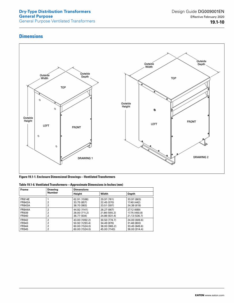
Dimensions
Figure 19.1-1. Enclosure Dimensional Drawings—Ventilated Transformers
Table 19.1-6. Ventilated Transformers—Approximate Dimensions in Inches (mm) Frame Drawing
NumberDimensions
Height Width Depth
FR814EFR842AFR843A
122
62.91 (1598)33.75 (857)38.70 (983)
29.97 (761)22.45 (570)23.51 (597)
33.97 (863)17.40 (442)24.38 (619)
FR844AFR939FR940
222
44.92 (1141)28.00 (711.2)36.77 (934)
26.27 (667)21.86 (555.2)24.86 (631.4)
27.12 (689)17.75 (450.8)21.13 (536.7)
FR942FR943FR944FR945
2222
43.00 (1092.2)50.92 (1293.4)60.00 (1524.0)60.00 (1524.0)
30.50 (774.7)34.49 (876)38.00 (965.2)45.00 (1143)
24.00 (609.6)31.48 (800)33.45 (849.6)36.00 (914.4)
Design Guide DG009001EN Effective February 2020
19 .1-10
Dry-Type Distribution TransformersGeneral PurposeGeneral Purpose Ventilated Transformers
EATON www.eaton.com
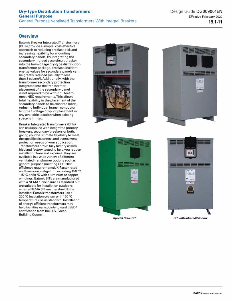
OverviewEaton’s Breaker Integrated Transformers (BITs) provide a simple, cost-effective approach to reducing arc flash risk and increasing flexibility for mounting secondary panels. By integrating the secondary molded case circuit breaker into the low-voltage dry-type distribution transformer package, arc flash incident energy values for secondary panels can be greatly reduced (usually to less than 8 cal/cm2). Additionally, with the transformer secondary protection integrated into the transformer, placement of the secondary panel is not required to be within 10 feet to meet NEC requirements. This allows total flexibility in the placement of the secondary panels to be closer to loads, reducing individual branch conductor lengths / voltage drop, or placement in any available location when existing space is limited.
Breaker Integrated Transformers (BITs) can be supplied with integrated primary breakers, secondary breakers or both, giving you the ultimate flexibility to meet the specific disconnect and overcurrent protection needs of your application. Transformers arrive fully factory assem-bled and factory tested to help you reduce installation time and expense. They are available in a wide variety of different ventilated transformer options such as general purpose (meeting DOE 2016 efficiency requirements), K-Factor rated and harmonic mitigating, including 150 °C, 115 °C or 80 °C with aluminum or copper windings. Eaton’s BITs are manufactured with a NEMA 1 enclosure as standard but are suitable for installation outdoors when a NEMA 3R weathershield kit is installed; Eaton’s transformers use a 220 °C insulation system with 150 °C temperature rise as standard. Installation of energy-efficient transformers may help facilities earn points toward LEEDT certification from the U.S. Green Building Council.
Special Color BIT BIT with Infrared Window
Design Guide DG009001EN Effective February 2020
19 .1-11
Dry-Type Distribution TransformersGeneral Purpose
EATON www.eaton.com
General Purpose Ventilated Transformers With Integral Breakers
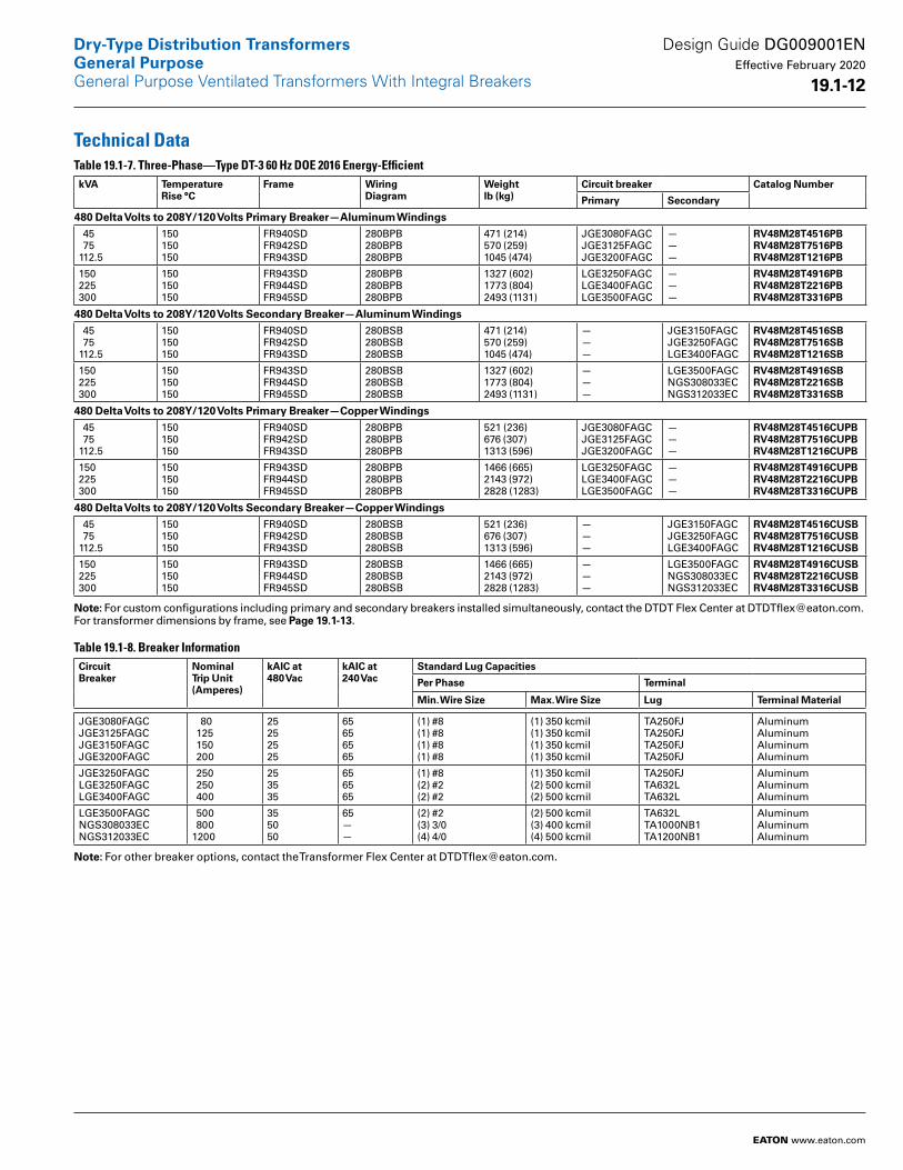
Technical DataTable 19.1-7. Three-Phase—Type DT-3 60 Hz DOE 2016 Energy-EfficientkVA Temperature
Rise °CFrame Wiring
DiagramWeight lb (kg)
Circuit breaker Catalog Number
Primary Secondary
480 Delta Volts to 208Y/120 Volts Primary Breaker—Aluminum Windings 45 75112.5
150150150
FR940SDFR942SDFR943SD
280BPB280BPB280BPB
471 (214)570 (259)1045 (474)
JGE3080FAGC JGE3125FAGC JGE3200FAGC
———
RV48M28T4516PBRV48M28T7516PBRV48M28T1216PB
150225300
150150150
FR943SDFR944SDFR945SD
280BPB280BPB280BPB
1327 (602)1773 (804)2493 (1131)
LGE3250FAGC LGE3400FAGC LGE3500FAGC
———
RV48M28T4916PBRV48M28T2216PBRV48M28T3316PB
480 Delta Volts to 208Y/120 Volts Secondary Breaker—Aluminum Windings 45 75112.5
150150150
FR940SDFR942SDFR943SD
280BSB280BSB280BSB
471 (214)570 (259)1045 (474)
———
JGE3150FAGCJGE3250FAGCLGE3400FAGC
RV48M28T4516SBRV48M28T7516SBRV48M28T1216SB
150225300
150150150
FR943SDFR944SDFR945SD
280BSB280BSB280BSB
1327 (602)1773 (804)2493 (1131)
———
LGE3500FAGCNGS308033EC NGS312033EC
RV48M28T4916SBRV48M28T2216SBRV48M28T3316SB
480 Delta Volts to 208Y/120 Volts Primary Breaker—Copper Windings 45 75112.5
150150150
FR940SDFR942SDFR943SD
280BPB280BPB280BPB
521 (236)676 (307)1313 (596)
JGE3080FAGC JGE3125FAGC JGE3200FAGC
———
RV48M28T4516CUPBRV48M28T7516CUPBRV48M28T1216CUPB
150225300
150150150
FR943SDFR944SDFR945SD
280BPB280BPB280BPB
1466 (665)2143 (972)2828 (1283)
LGE3250FAGC LGE3400FAGC LGE3500FAGC
———
RV48M28T4916CUPBRV48M28T2216CUPBRV48M28T3316CUPB
480 Delta Volts to 208Y/120 Volts Secondary Breaker—Copper Windings 45 75112.5
150150150
FR940SDFR942SDFR943SD
280BSB280BSB280BSB
521 (236)676 (307)1313 (596)
———
JGE3150FAGCJGE3250FAGCLGE3400FAGC
RV48M28T4516CUSBRV48M28T7516CUSBRV48M28T1216CUSB
150225300
150150150
FR943SDFR944SDFR945SD
280BSB280BSB280BSB
1466 (665)2143 (972)2828 (1283)
———
LGE3500FAGCNGS308033EC NGS312033EC
RV48M28T4916CUSBRV48M28T2216CUSBRV48M28T3316CUSB
Note: For custom configurations including primary and secondary breakers installed simultaneously, contact the DTDT Flex Center at [email protected]. For transformer dimensions by frame, see Page 19 .1-13.
Table 19.1-8. Breaker InformationCircuit Breaker
Nominal Trip Unit (Amperes)
kAIC at 480 Vac
kAIC at 240 Vac
Standard Lug Capacities
Per Phase Terminal
Min . Wire Size Max . Wire Size Lug Terminal Material
JGE3080FAGCJGE3125FAGCJGE3150FAGCJGE3200FAGC
80 125 150 200
25252525
65656565
(1) #8(1) #8(1) #8(1) #8
(1) 350 kcmil(1) 350 kcmil(1) 350 kcmil(1) 350 kcmil
TA250FJTA250FJTA250FJTA250FJ
AluminumAluminumAluminumAluminum
JGE3250FAGCLGE3250FAGCLGE3400FAGC
250 250 400
253535
656565
(1) #8(2) #2(2) #2
(1) 350 kcmil(2) 500 kcmil(2) 500 kcmil
TA250FJTA632LTA632L
AluminumAluminumAluminum
LGE3500FAGCNGS308033EC NGS312033EC
500 8001200
355050
65——
(2) #2(3) 3/0(4) 4/0
(2) 500 kcmil(3) 400 kcmil(4) 500 kcmil
TA632LTA1000NB1TA1200NB1
AluminumAluminumAluminum
Note: For other breaker options, contact the Transformer Flex Center at [email protected].
Design Guide DG009001EN Effective February 2020
19 .1-12
Dry-Type Distribution TransformersGeneral PurposeGeneral Purpose Ventilated Transformers With Integral Breakers
EATON www.eaton.com
Dimensions
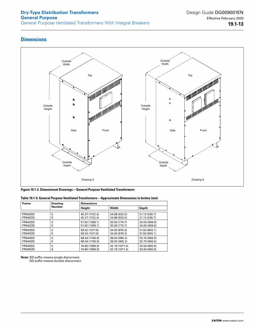
Figure 19.1-2. Dimensional Drawings—General Purpose Ventilated Transformers
Table 19.1-9. General Purpose Ventilated Transformers—Approximate Dimensions in Inches (mm) Frame Drawing
NumberDimensions
Height Width Depth
FR940SDFR940DD
56
45.37 (1152.4)45.37 (1152.4)
24.88 (632.0)24.88 (632.0)
21.13 (536.7)21.13 (536.7)
FR942SDFR942DD
56
51.50 (1308.1)51.50 (1308.1)
30.50 (774.7)30.50 (774.7)
24.00 (609.6)24.00 (609.6)
FR943SDFR943DD
56
59.52 (1511.8)59.52 (1511.8)
34.50 (876.3)34.50 (876.3)
31.50 (800.1)31.50 (800.1)
FR944SDFR944DD
56
68.54 (1740.9)68.54 (1740.9)
38.00 (965.2)38.00 (965.2)
33.70 (856.0)33.70 (856.0)
FR945SDFR945DD
56
74.80 (1899.9)74.80 (1899.9)
42.18 (1071.4)42.18 (1071.4)
33.50 (850.9)33.50 (850.9)
Note: SD suffix means single disconnect. DD suffix means double disconnect.
Top Top
SideSide FrontFront
Outside Width
Outside Width
Outside Height
Outside Height
Outside Depth
Outside Depth
Drawing 6 Drawing 5
Design Guide DG009001EN Effective February 2020
19 .1-13
Dry-Type Distribution TransformersGeneral PurposeGeneral Purpose Ventilated Transformers With Integral Breakers
EATON www.eaton.com
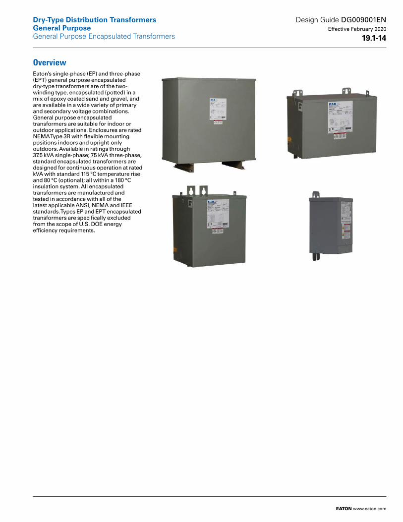
OverviewEaton’s single-phase (EP) and three-phase (EPT) general purpose encapsulated dry-type transformers are of the two-winding type, encapsulated (potted) in a mix of epoxy coated sand and gravel, and are available in a wide variety of primary and secondary voltage combinations. General purpose encapsulated transformers are suitable for indoor or outdoor applications. Enclosures are rated NEMA Type 3R with flexible mounting positions indoors and upright-only outdoors. Available in ratings through 37.5 kVA single-phase; 75 kVA three-phase, standard encapsulated transformers are designed for continuous operation at rated kVA with standard 115 °C temperature rise and 80 °C (optional); all within a 180 °C insulation system. All encapsulated transformers are manufactured and tested in accordance with all of the latest applicable ANSI, NEMA and IEEE standards. Types EP and EPT encapsulated transformers are specifically excluded from the scope of U.S. DOE energy efficiency requirements.
Design Guide DG009001EN Effective February 2020
19 .1-14
Dry-Type Distribution TransformersGeneral Purpose
EATON www.eaton.com
General Purpose Encapsulated Transformers
Technical Data
General Construction Features of General Purpose Encapsulated Transformers Rated 600 V and BelowEaton’s single-phase and three-phase general purpose encapsulated dry-type transformers are of the two-winding type, self-cooled, and are available in a wide variety of primary and secondary voltage combinations.
Eaton’s transformers are designed, manufactured and tested in accordance with all of the latest applicable ANSI, NEMA and IEEE standards. All 600 V-class encapsulated transformers with ratings through 112.5 kVA are UL listed and CSA certified, and bear the UL and CSA labels.
These transformers are designed for continuous operation at rated kVA for 24 hours a day, 365 days a year, with normal life expectancy as defined in ANSI C57.96. Encapsulated transformers are outside the scope of U.S. energy efficiency law 10 CFR Part 431 (DOE 2016).
Insulation SystemsThe design life of transformers having different insulation systems is the same; the lower temperature systems are designed for the same life as the higher temperature systems.
Eaton’s encapsulated transformers are manufactured using a 180 °C insulation system. Required performance is obtained without exceeding the insulation system rating at rated temperature rise in a 40 °C maximum ambient, with an average ambient temperature of 30 °C over a 24-hour period.
All insulation materials are flame-retardant and do not support combustion as defined in ASTM Standard Test Method D635.
Core and Coil AssembliesThe transformer core is constructed using high-grade, non-aging, silicon steel with high-magnetic permeability, and low hysteresis and eddy current losses. Maximum magnetic flux densities are substantially below the saturation point. The transformer core volume allows for efficient transformer operation at 10% above the nominal tap voltage. The core laminations are tightly clamped and compressed. Coils are wound of electrical grade aluminum or copper, and are of continuous wound construction. The BIL (basic impulse level) for all 600 V-class windings is 10 kV. In encapsulated transformers, the core and coil assembly is completely encased in a proportioned mixture of resin or epoxy, and aggregate to provide a moisture-proof, shock-resistant seal. The core and coil encapsulation system is designed to minimize the audible sound level.
TapsPrimary taps are available on many Eaton encapsulated transformers to allow compensation for source voltage variations.
Winding TerminationsPrimary and secondary windings are terminated in the wiring compartment. Encapsulated units have copper leads or stabs brought out for connections. Ventilated transformers have leads brought out to aluminum or copper pads that are pre-drilled to accept Cu/Al lugs. Aluminum-wound trans formers have aluminum pads; copper-wound transformers have copper pads. Lugs are not supplied with Eaton’s transformers; however, lug kits are available as a field-installed accessory. Eaton recommends external cables be rated 90 °C (sized at 75 °C ampacity) for encapsulated designs and rated 75 °C for ventilated designs.
Series-Multiple WindingsSeries-multiple windings consist of two similar coils in each winding that can be connected in series or parallel (multiple). Transformers with series-multiple windings are desig nated with an “x” or a “/” between the voltage ratings, such as voltages of “240 x 480” or “120/240.” If the series-multiple winding is designated by an “x,” the winding can be connected only in series or parallel. With a “/” designation, a mid-point also becomes available in addition to the series or parallel connection. As an example, a 240 x 480 winding can be connected for either 240 (parallel) or 480 (series). A 120/240 winding can be connected for either 120 (parallel) or 240 (series), or 240 with a 120 mid-point.
EnclosuresThe transformer enclosure is made of heavy-gauge steel and is finished using a continuous process of degreasing, cleaning and phosphatizing, followed by electrostatic deposition of a thermo-setting polyester powder coating and subsequent baking. The coating color is ANSI 61 and is UL recognized for outdoor use. In compliance with NEMA ST-20, Eaton’s transformers are designed such that the maximum temperature on the top of the enclosure does not exceed 50 °C rise above the ambient temperature.
For encapsulated transformers, the standard enclosure construction is totally enclosed, non-ventilated NEMA 3R, with lifting provisions. NEMA 4X rated encapsulated transformers are available as an option.
Wall-mounting brackets are provided on many Eaton encapsulated transformers. These mounting brackets are designed to provide the proper spacing between the mounting surface and the transformer enclosure.
To ensure proper ventilation and cooling of the transformer, follow manufacturer’s recommended clearances around encapsulated transformers.
Design Guide DG009001EN Effective February 2020
19 .1-15
Dry-Type Distribution TransformersGeneral PurposeGeneral Purpose Encapsulated Transformers
EATON www.eaton.com
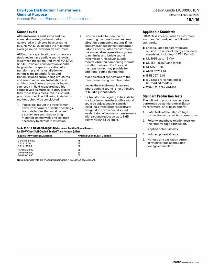
Sound LevelsAll transformers emit some audible sound due mainly to the vibration generated in their core by alternating flux. NEMA ST-20 defines the maximum average sound levels for transformers.
All Eaton encapsulated transformers are designed to have audible sound levels lower than those required by NEMA ST-20 (2014). However, consideration should be given to the specific location of a transformer and its installation to minimize the potential for sound transmission to surrounding structures and sound reflection. Installation and ambient conditions at a specific location can result in field-measured audible sound levels as much as 15 dBA greater than those levels measured in a sound-proof chamber. The following installation methods should be considered:
1. If possible, mount the transformer away from corners of walls or ceilings. For installations that must be near a corner, use sound-absorbing materials on the walls and ceiling if necessary to eliminate reflection.
2. Provide a solid foundation for mounting the transformer and use vibration-dampening mounts if not already provided in the transformer. Eaton’s encapsulated transformers use a special encapsulation system to minimize and isolate sound transmission. However, supple- mental vibration dampening mounts installed between the floor and the transformer may provide for additional sound dampening.
3. Make electrical connections to the transformer using flexible conduit.
4. Locate the transformer in an area where audible sound is not offensive to building inhabitants.
5. If a transformer is going to be installed in a location where the audible sound could be objectionable, consider installing a transformer specifically designed to have reduced sound levels. Eaton offers many transformers with a sound reduction up to 5 dB below NEMA ST-20 limits.
Table 19.1-10. NEMA ST-20 (2014) Maximum Audible Sound Levels for 600 V Class Self-Cooled Sealed Transformers (dBA)Equivalent Winding kVA Range Average Sound Level Decibels
3.00 and below3.01 to 9.009.01 to 15.00
454550
15.01 to 30.0030.01 to 50.0050.01 to 75.00
505055
Note: Sound levels are measured using the A-weighted scale (dBA).
Applicable Standards600 V-class encapsulated transformers are manufactured per the following standards:
■ Encapsulated transformers are out side the scope of energy efficiency mandates, including 10 CFR Part 431
■ UL 5085 up to 15 kVA ■ UL 1561 15 kVA and larger■ NEMA ST-20■ ANSI C57.12.01■ IEEE C57.12.01■ IEC 61558 for single-phase CE-marked models
■ CSA C22.2 No. 47-M90
Standard Production TestsThe following production tests are performed as standard on all Eaton transformers, prior to shipment:
1. Ratio tests at the rated voltage connection and at all tap connections.
2. Polarity and phase relation tests on the rated voltage connection.
3. Applied potential tests.
4. Induced potential tests.
5. No-load and excitation current at rated voltage on the rated voltage connection.
Design Guide DG009001EN Effective February 2020
19 .1-16
Dry-Type Distribution TransformersGeneral PurposeGeneral Purpose Encapsulated Transformers
EATON www.eaton.com

OperationEaton’s encapsulated transformers are designed for continuous operation at rated kVA for 24 hours a day, 365 days a year, with normal life expectancy as defined in ANSI C57.96.
Short-term overload capacity is designed into transformers, as required by ANSI. Encapsulated transformers will deliver 200% of nameplate load for 30 minutes; 150% of nameplate load for 1 hour; and 125% of nameplate load for 4 hours without being damaged, provided that a constant 50% load precedes and follows the overload. Refer to ANSI C57.96-01.250 for additional limitations.
Note: Continuous overload capacity is not deliberately designed into transformers because the design objective is to be within the allowable winding temperature rise at nameplate full load capacity.
Table 19.1-11. Rated Line Amperes for kVA and Voltages of Single-Phase Transformers kVARating
Rated Line Voltage
120 208 240 277 480 600 2400 4160 4800
1 1.5 2 3
8.3 12.5 16.7 25.0
4.8 7.2 9.6 14.4
4.2 6.3 8.3 12.5
3.6 5.4 7.2 10.8
2.1 3.1 4.2 6.3
1.7 2.5 3.3 5.0
0.4 0.6 0.8 1.3
0.20.40.50.7
0.20.30.40 6
5 7.51015
41.7 62.5 83.3125.0
24.0 36.6 48.1 72.1
20.8 31.3 41.7 62.5
18.0 27.1 36.1 54.2
10.415.620.831.3
8.312.516.725.0
2.1 3.1 4.2 6.3
1.21.82.43.6
1.01.62.13.1
2537.5
208.3312.5
120.2180.3
104.2156.3
90.3135.4
52.178.1
41.762.5
10.415.6
6.09.0
5.27.8
Note: Line Current = (kVA x 1000)/Line Voltage.
Table 19.1-12. Rated Line Amperes for kVA and Voltages of Three-Phase Transformers kVARating
Rated Line Voltage
208 240 480 600 2400 4160 4800
3 6 9
8.3 16.7 25.0
7.2 14.4 21.6
3.6 7.210.8
2.9 5.8 8.7
0.7 1.4 2.2
0.4 0.8 1.3
0.40.71.1
15304575
41.6 83.3125.0208.2
36.1 72.2108.4180.4
18.036.154.290.2
14.428.943.372.2
3.6 7.210.918.0
2.1 4.2 6.310.4
1.83.65.49.0
Note: Three-Phase Line Current = (kVA x 1000)/(Line Voltage x 1.732).
Design Guide DG009001EN Effective February 2020
19 .1-17
Dry-Type Distribution TransformersGeneral PurposeGeneral Purpose Encapsulated Transformers
EATON www.eaton.com
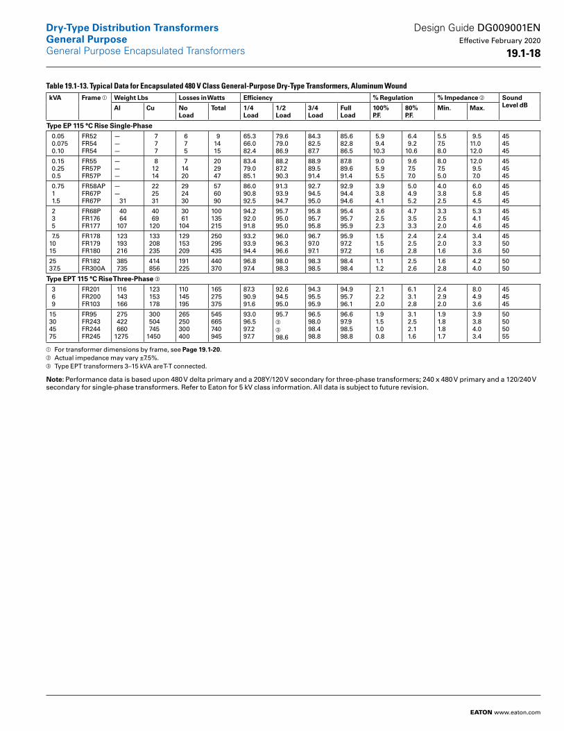
Table 19.1-13. Typical Data for Encapsulated 480 V Class General-Purpose Dry-Type Transformers, Aluminum Wound kVA Frame a Weight Lbs Losses in Watts Efficiency % Regulation % Impedance b Sound
Level dBAl Cu No Load
Total 1/4Load
1/2Load
3/4Load
FullLoad
100%P .F .
80%P .F .
Min . Max .
Type EP 115 °C Rise Single-Phase 0.05 0.075 0.10
FR52FR54FR54
———
7 7 7
6 7 5
9 14 15
65.366.082.4
79.679.086.9
84.382.587.7
85.682.886.5
5.9 9.410.3
6.4 9.210.6
5.57.58.0
9.511.012.0
454545
0.15 0.25 0.5
FR55FR57PFR57P
———
8 12 14
7 14 20
20 29 47
83.479.085.1
88.287.290.3
88.989.591.4
87.889.691.4
9.0 5.9 5.5
9.6 7.5 7.0
8.07.55.0
12.0 9.5 7.0
454545
0.75 1 1.5
FR58APFR67PFR67P
—— 31
22 25 31
29 24 30
57 60 90
86.090.892.5
91.393.994.7
92.794.595.0
92.994.494.6
3.9 3.8 4.1
5.0 4.9 5.2
4.03.82.5
6.0 5.8 4.5
454545
2 3 5
FR68PFR176FR177
40 64 107
40 69 120
30 61104
100135215
94.292.091.8
95.795.095.0
95.895.795.8
95.495.795.9
3.6 2.5 2.3
4.7 3.5 3.3
3.32.52.0
5.3 4.1 4.6
454545
7.51015
FR178FR179FR180
123 193 216
133 208 235
129153209
250295435
93.293.994.4
96.096.396.6
96.797.097.1
95.997.297.2
1.5 1.5 1.6
2.4 2.5 2.8
2.42.01.6
3.4 3.3 3.6
455050
2537.5
FR182FR300A
385 735
414 856
191225
440370
96.897.4
98.098.3
98.398.5
98.498.4
1.1 1.2
2.5 2.6
1.62.8
4.2 4.0
5050
Type EPT 115 °C Rise Three-Phase c
3 6 9
FR201FR200FR103
116 143 166
123 153 178
110145195
165275375
87.390.991.6
92.694.595.0
94.395.595.9
94.995.796.1
2.1 2.2 2.0
6.1 3.1 2.8
2.42.92.0
8.0 4.9 3.6
454545
15304575
FR95FR243FR244FR245
275 422 6601275
300 504 7451450
265250300400
545665740945
93.096.597.297.7
95.7c
c
98.6
96.598.098.498.8
96.697.998.598.8
1.9 1.5 1.0 0.8
3.1 2.5 2.1 1.6
1.91.81.81.7
3.9 3.8 4.0 3.4
50505055
a For transformer dimensions by frame, see Page 19 .1-20.b Actual impedance may vary ±7.5%.c Type EPT transformers 3–15 kVA are T-T connected.
Note: Performance data is based upon 480 V delta primary and a 208Y/120 V secondary for three-phase transformers; 240 x 480 V primary and a 120/240 V secondary for single-phase transformers. Refer to Eaton for 5 kV class information. All data is subject to future revision.
Design Guide DG009001EN Effective February 2020
19 .1-18
Dry-Type Distribution TransformersGeneral PurposeGeneral Purpose Encapsulated Transformers
EATON www.eaton.com
Encapsulated copper transformer typical data to come at a later date.
Design Guide DG009001EN Effective February 2020
19 .1-19
Dry-Type Distribution TransformersGeneral PurposeGeneral Purpose Encapsulated Transformers
EATON www.eaton.com
Dimensions
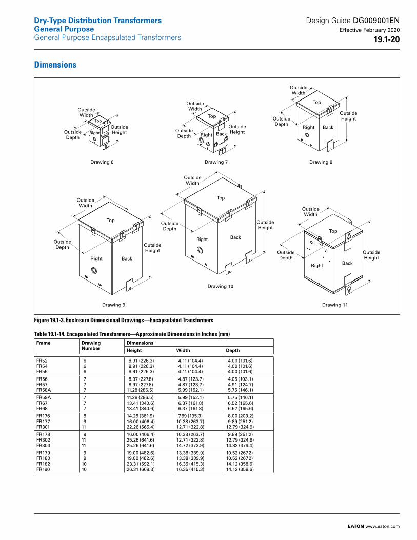
Figure 19.1-3. Enclosure Dimensional Drawings—Encapsulated Transformers
Table 19.1-14. Encapsulated Transformers—Approximate Dimensions in Inches (mm) Frame Drawing
NumberDimensions
Height Width Depth
FR52FR54FR55
6 6 6
8.91 (226.3) 8.91 (226.3) 8.91 (226.3)
4.11 (104.4) 4.11 (104.4) 4.11 (104.4)
4.00 (101.6) 4.00 (101.6) 4.00 (101.6)
FR56FR57FR58A
7 7 7
8.97 (227.8) 8.97 (227.8)11.28 (286.5)
4.87 (123.7) 4.87 (123.7) 5.99 (152.1)
4.06 (103.1) 4.91 (124.7) 5.75 (146.1)
FR59AFR67FR68
7 7 7
11.28 (286.5)13.41 (340.6)13.41 (340.6)
5.99 (152.1) 6.37 (161.8) 6.37 (161.8)
5.75 (146.1) 6.52 (165.6) 6.52 (165.6)
FR176FR177FR301
8 911
14.25 (361.9)16.00 (406.4)22.26 (565.4)
7.69 (195.3)10.38 (263.7)12.71 (322.8)
8.00 (203.2) 9.89 (251.2)12.79 (324.9)
FR178FR302FR304
91111
16.00 (406.4)25.26 (641.6)25.26 (641.6)
10.38 (263.7)12.71 (322.8)14.72 (373.9)
9.89 (251.2)12.79 (324.9)14.82 (376.4)
FR179FR180FR182FR190
9 91010
19.00 (482.6)19.00 (482.6)23.31 (592.1)26.31 (668.3)
13.38 (339.9)13.38 (339.9)16.35 (415.3)16.35 (415.3)
10.52 (267.2)10.52 (267.2)14.12 (358.6)14.12 (358.6)
Right
Top
Drawing 10
Top
BackRight
Drawing 11
Top
BackRight
Drawing 6
Top
Right Back
Drawing 7
Top
Right Back
Drawing 8
Top
Right Back
Drawing 9
OutsideWidth
OutsideDepth
OutsideHeight
OutsideWidth
OutsideDepth
OutsideHeight
OutsideWidth
OutsideDepth
OutsideHeight
OutsideWidth
OutsideDepth Outside
Height
OutsideWidth
OutsideDepth
OutsideHeight
OutsideWidth
OutsideDepth
OutsideHeight
Back
Design Guide DG009001EN Effective February 2020
19 .1-20
Dry-Type Distribution TransformersGeneral PurposeGeneral Purpose Encapsulated Transformers
EATON www.eaton.com

Figure 19.1-4. Enclosure Dimensional Drawings—Encapsulated Transformers
Table 19.1-15. Encapsulated Transformers—Approximate Dimensions in Inches (mm)Frame Drawing
NumberDimensions
Height Width Depth
FR132FR300AFR57P
131214
20.67 (525.0)28.24 (717.3) 9.34 (237.2)
19.02 (483.1)22.42 (569.5) 4.45 (113.0)
13.59 (345.2)14.06 (357.1) 5.18 (131.6)
FR58APFR567PFR568P
141414
11.68 (296.7)13.03 (330.9)13.78 (350.0)
4.99 (126.7) 5.74 (145.8) 6.22 (158.0)
5.99 (152.1) 6.56 (166.6) 6.32 (160.5)
FrontLeft
Top
Drawing 13Front
Left
Top
Drawing 12
Top
BackRight
Drawing 14
OutsideWidth
OutsideDepth
OutsideHeight
OutsideWidth
OutsideDepth
OutsideHeight
OutsideWidth
OutsideDepth
OutsideHeight
Design Guide DG009001EN Effective February 2020
19 .1-21
Dry-Type Distribution TransformersGeneral PurposeGeneral Purpose Encapsulated Transformers
EATON www.eaton.com
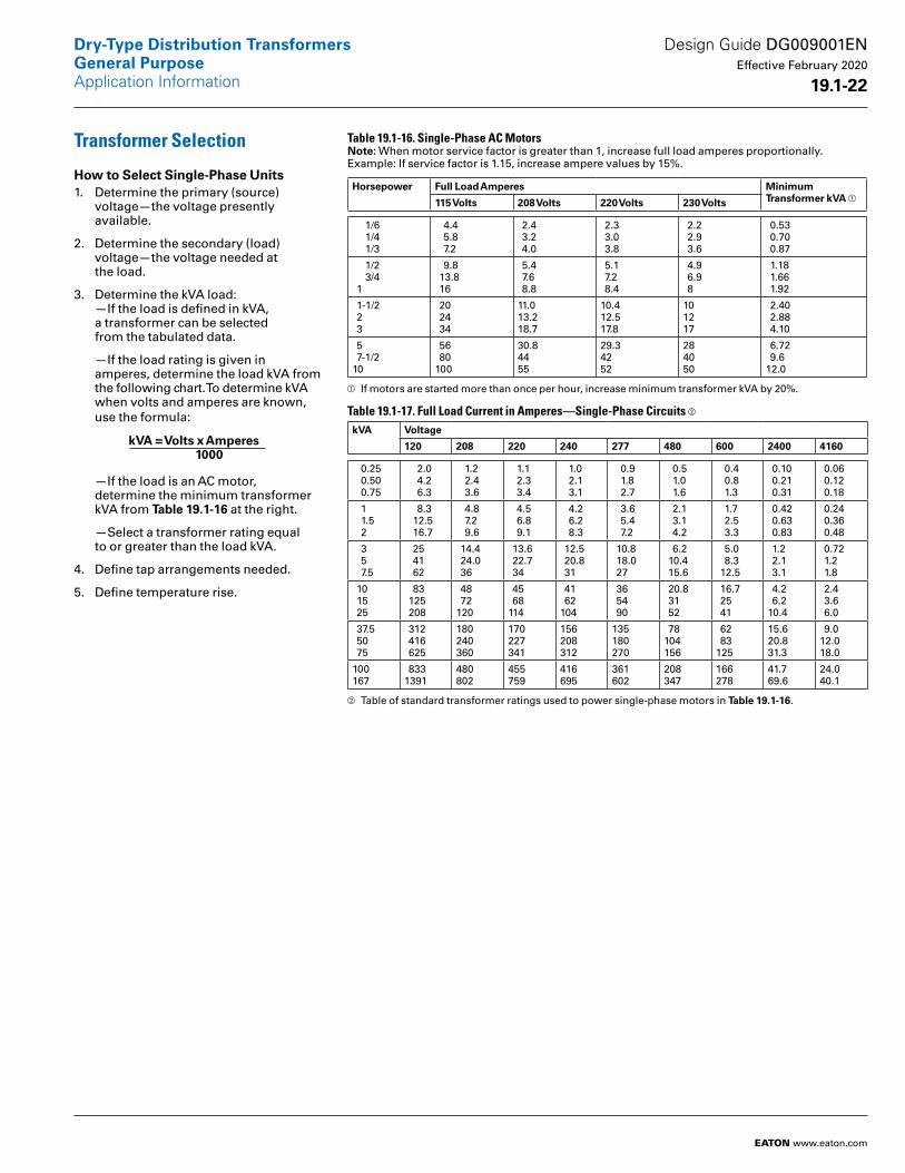
Transformer Selection
How to Select Single-Phase Units1. Determine the primary (source)
voltage—the voltage presently available.
2. Determine the secondary (load) voltage—the voltage needed at the load.
3. Determine the kVA load: —If the load is defined in kVA, a transformer can be selected from the tabulated data.
—If the load rating is given in amperes, determine the load kVA from the following chart. To deter mine kVA when volts and amperes are known, use the formula:
—If the load is an AC motor, determine the minimum trans former kVA from Table 19 .1-16 at the right.
—Select a transformer rating equal to or greater than the load kVA.
4. Define tap arrangements needed.
5. Define temperature rise.
Table 19.1-16. Single-Phase AC MotorsNote: When motor service factor is greater than 1, increase full load amperes proportionally. Example: If service factor is 1.15, increase ampere values by 15%.
Horsepower Full Load Amperes MinimumTransformer kVA a115 Volts 208 Volts 220 Volts 230 Volts
1/6 1/4 1/3
4.4 5.8 7.2
2.4 3.2 4.0
2.3 3.0 3.8
2.2 2.9 3.6
0.53 0.70 0.87
1/2 3/4 1
9.8 13.8 16
5.4 7.6 8.8
5.1 7.2 8.4
4.9 6.9 8
1.18 1.66 1.92
1-1/2 2 3
20 24 34
11.013.218.7
10.412.517.8
101217
2.40 2.88 4.10
5 7-1/210
56 80100
30.84455
29.34252
284050
6.72 9.612.0
a If motors are started more than once per hour, increase minimum transformer kVA by 20%.
Table 19.1-17. Full Load Current in Amperes—Single-Phase Circuits b kVA Voltage
120 208 220 240 277 480 600 2400 4160
0.25 0.50 0.75
2.0 4.2 6.3
1.2 2.4 3.6
1.1 2.3 3.4
1.0 2.1 3.1
0.9 1.8 2.7
0.5 1.0 1.6
0.4 0.8 1.3
0.10 0.21 0.31
0.06 0.12 0.18
1 1.5 2
8.3 12.5 16.7
4.8 7.2 9.6
4.5 6.8 9.1
4.2 6.2 8.3
3.6 5.4 7.2
2.1 3.1 4.2
1.7 2.5 3.3
0.42 0.63 0.83
0.24 0.36 0.48
3 5 7.5
25 41 62
14.4 24.0 36
13.6 22.7 34
12.5 20.8 31
10.8 18.0 27
6.2 10.4 15.6
5.0 8.3 12.5
1.2 2.1 3.1
0.72 1.2 1.8
10 15 25
83 125 208
48 72120
45 68114
41 62104
36 54 90
20.8 31 52
16.7 25 41
4.2 6.210.4
2.4 3.6 6.0
37.5 50 75
312 416 625
180240360
170227341
156208312
135180270
78104156
62 83125
15.620.831.3
9.012.018.0
100167
8331391
480802
455759
416695
361602
208347
166278
41.769.6
24.040.1
b Table of standard transformer ratings used to power single-phase motors in Table 19 .1-16.
kVA = Volts x Amperes 1000
Design Guide DG009001EN Effective February 2020
19 .1-22
Dry-Type Distribution TransformersGeneral Purpose
EATON www.eaton.com
Application Information

Three-Phase Transformers
How to Select Three-Phase Units1. Determine the primary (source)
voltage—the voltage presently available.
2. Determine the secondary (load) voltage—the voltage needed at the load.
3. Determine the kVA load: — If the load is defined in kVA, a transformer can be selected from the tabulated data.
— If the load rating is given in amperes, determine the load kVA from the following chart. To deter mine kVA when volts and amperes are known, use the formula:
— If the load is an AC motor, deter mine the minimum transformer kVA from Table 19 .1-18 at the right.
— Select a transformer rating equal to or greater than the load kVA.
4. Define tap arrangements needed.
5. Define temperature rise.
Using the above procedure, select the transformer from the listings in this catalog.
Table 19.1-18. Three-Phase AC MotorsHorsepower Full Load Amperes Minimum
Transformer kVA c208 Volts 230 Volts 380 Volts 460 Volts 575 Volts
1/2 3/4 1
2.2 3.1 4.0
2.0 2.8 3.6
1.2 1.7 2.2
1.0 1.4 1.8
0.8 1.1 1.4
0.9 1.2 1.5
1-1/2 2 3
5.7 7.5 10.7
5.2 6.8 9.6
3.1 4.1 5.8
2.6 3.4 4.8
2.1 2.7 3.9
2.1 2.7 3.8
5 7-1/2 10
16.7 24 31
15.2 22 28
9.2 14 17
7.6 11 14
6.1 9 11
6.3 9.2 11.2
15 20 25
46 59 75
42 54 68
26 33 41
21 27 34
17 22 27
16.6 21.6 26.6
30 40 50
88114143
80104130
48 63 79
40 52 65
32 41 52
32.4 43.2 52
60 75100
170211273
154192248
93116150
77 96124
62 77 99
64 80103
125150200
342396528
312360480
189218291
156180240
125144192
130150200
a If motors are started more than once per hour, increase minimum transformer kVA by 20%.Note: When motor service factor is greater than 1, increase full load amperes proportionally. Example: If service factor is 1.15, increase above ampere values by 15%.
Table 19.1-19. Full Load Current in Amperes—Three-Phase CircuitskVA Voltage
208 240 380 480 600 2400 4160
3 6 9
8.3 16.6 25
7.2 14.4 21.6
4.6 9.1 13.7
3.6 7.2 10.8
2.9 5.8 8.6
0.72 1.4 2.2
0.42 0.83 1.2
15 22.5 30
41.7 62.4 83.4
36.1 54.1 72.3
22.8 34.2 45.6
18.0 27.1 36.1
14.4 21.6 28.9
3.6 5.4 7.2
2.1 3.1 4.2
37.5 45 50
104 124 139
90.3 108 120
57.0 68.4 76
45.2 54.2 60.1
36.1 43.4 48.1
9.0 10.8 12.0
5.2 6.3 6.9
75 112.5 150
208 312 416
180 270 360
114 171 228
90 135 180
72108144
18.0 27.1 36.1
10.4 15.6 20.8
225 300 500
624 8321387
541 7211202
342 456 760
270 360 601
216288481
54.2 72.2120
31.3 41.6 69.4
7501000
20842779
18062408
11401519
9031204
723963
180241
104139
kVA = Volts x Amperes x 1 .732 1000
Design Guide DG009001EN Effective February 2020
19 .1-23
Dry-Type Distribution TransformersGeneral PurposeApplication Information
EATON www.eaton.com

Standards and CertificationsEaton dry-type distribution transformers are approved, listed, recognized or may comply with the following standards.
Table 19.1-20. Engineering StandardsCatalog Product Name
UL Standard a
UL/cUL File Number
UL Listed Control Number
cUL Energy Efficiency Verification File Number
CSA File Number
Insulation System Temp/ºC
kVASingle- Phase
kVAThree- Phase
Applicable IEC Standard
Industrial Control TransformerMTE 5085 E46323 702X — — 105 0.025–1.5 N/A 61558
MTE 5085 E46323 702X — — 180 0.05–5 N/A 61558
Encapsulated TransformerAP 5085 E10156 591H — — 180 3–10 N/A 61558
AP 1561 E78389 591H — — 180 15 N/A 61558
EP 5085 E10156 591H — LR60545 180 0.05–10 N/A 61558
EP 1561 E78389 591H — LR60545 b 180 15–37.5 N/A 61558 c / 726 d
EPT 5085 E10156 591H — LR60545 180 N/A 3–9 61558 e / 726 f
EP 1561 E78389 591H — LR60545 g 180 N/A 15–75 726
MPC 1062 E53449 591H — LR60546 180 3–25 15–30 —
Ventilated TransformerDS-3 1561 E78389 591H EV33871 h — 220 7.5–167 N/A 60726
DS-3 1561 E78389 591H EV33871 i — 220 N/A 7.5–750 60726
KT 1561 E78389 591H EV33871 i — 220 N/A 7.5–750 N/A
a UL 5085 replaces UL 506.b Applies to 25 kVA.c Applies to 15–25 kVA.d Applies to 37.5 kVA.e Applies to 3 kVA.f Applies to 5–9 kVA.g Applies to 30 kVA.h Applies to 15–167 kVA.i Applies to 15–300 kVA.
In addition to the above standards, Eaton dry-type distribution transformers are also manufactured in compliance with the applicable standards listed below.
Not all of the following standards apply to every transformer.
NEC: National Electrical Code.
NEMA ST-1: Specialty Transformers (C89.1) (control transformers).
NEMA ST-20: General-Purpose Transformers.
DOE 2016 Final Rule: CFR Title 10 Chapter II Part 431, Appendix A of Subpart K 2016.
NEMA 250: Enclosures for Electrical Equipment (1000 volts maximum).
IEEE C57 .12 .01: General Requirements for Dry-Type Distribution and Power Transformers (including those with solidcast and/or resin-encapsulated windings).
ANSI C57 .12 .70: Terminal Markings and Connections for Distribution and Power Transformers.
ANSI C57 .12 .91: Standard Test Code for Dry-Type Distribution and Power Transformers.
CSA C22 No . 47-M90: Air-Cooled Transformers (Dry-Type).
CSA C9-M1981: Dry-Type Transformers.
CSA C22 .2 No . 66: Specialty Transformers.
CSA 802-94: Maximum Losses for Distribution, Power and Dry-Type Transformers.
NEMA TP-1: Guide for Determining Energy Efficiency for Distribution Transformers (rescinded).
NEMA TP-2: Standard Test Method for Measuring the Energy Consumption of Distribution Transformers (rescinded).
NEMA TP-3: Standard for the Labeling of Distribution Transformer Efficiency (rescinded).
Design Guide DG009001EN Effective February 2020
19 .1-24
Dry-Type Distribution TransformersGeneral PurposeApplication Information
EATON www.eaton.com
Glossary of Transformer TermsAir cooled: A transformer that is cooled by the natural circulation of air around, or through, the core and coils.
Ambient noise level: The existing or inherent sound level of the area surrounding the transformer, prior to energizing the transformer. Measured in decibels.
Ambient temperature: The temperature of the air surrounding the transformer into which the heat of the transformer is dissipated.
Ampacity: The current-carrying capacity of an electrical conductor under stated thermal conditions. Expressed in amperes.
Ampere: The practical unit of electric current.
Attenuation: A decrease in signal power or voltage. Unit of measure is dB.
Autotransformer: A transformer in which part of the winding is common to both the primary and the secondary circuits.
Banked: Two or more single-phase transformers wired together to supply a three-phase load. Three single-phase transformers can be “banked” together to support a three-phase load. For example, three 10 kVA single-phase transformers “banked” together will have a 30 kVA three-phase capacity.
BIL: Basic impulse level. The ability of a transformer’s insulation system to withstand high voltage surges. All Eaton 600 V-class transformers have a 10 kV BIL rating.
BTU: British thermal unit. In North America, the term “BTU” is used to describe the heat value (energy content) of fuels, and also to describe the power of heating and cooling systems, such as furnaces, stoves, barbecue grills and air conditioners. When used as a unit of power, BTU “per hour” (BTU/h) is understood, though this is often abbreviated to just “BTU.”
Buck-Boost: The name of a standard, single-phase, two-winding transformer application with the low-voltage secondary windings connected as an autotransformer for boosting (increasing) or bucking (decreasing) voltages in small amounts. Applications can either be single-phase or three-phase.
CE: Mark to indicate third-party approved or self-certification to specific requirements of the European community.
Celsius (centigrade): Metric temperature measure.
°F = (1.8 x °C) + 32
°C = (°F-32) / 1.8
Center tap: A reduced capacity tap at the mid-point of a winding. The center tap on three-phase delta-delta transformers is called a lighting tap. It provides 5% of the transformer’s kVA for single-phase loads.
Certified tests: Actual values taken during production tests and certified as applying to a given unit shipped on a specific order. Certified tests are serial number–specific.
Common mode: Electrical noise or voltage fluctuation that occurs between all of the line leads and the common ground, or between ground and line or neutral.
Compensated transformer: A transformer with a turns ratio that provides a higher than nameplate output (secondary) voltage at no load, and nameplate output (secondary) voltage at rated load. It is common for small transformers (2 kVA and less) to be compensated.
Conductor losses: Losses (expressed in watts) in a transformer that are incidental to carrying a load: coil resistance, stray loss due to stray fluxes in the windings, core clamps, and the like, as well as circulating currents (if any) in parallel windings. Also called load losses.
Continuous duty rating: The load that a transformer can handle indefinitely without exceeding its specified temperature rise.
Core losses: Losses (expressed in watts) caused by magnetization of the core and its resistance to magnetic flux. Also called no-load losses or excitation losses. Core losses are always present when the transformer is energized.
CSA: Canadian Standards Association. The Canadian equivalent of Underwriters Laboratories (UL).
CSL3: Candidate Standard Level 3 (CSL3) design criteria developed by the U.S. Department of Energy.
cUL: Mark to indicate UL Certification to specific CSA Standards.
Decibel (dB): Unit of measure used to express the magnitude of a change in signal or sound level.
Delta connection: A standard three-phase connection with the ends of each phase winding connected in series to form a closed loop with each phase 120 degrees from the other. Sometimes referred to as three-wire.
Dielectric tests: Tests that consist of the application of a voltage higher than the rated voltage for a specified time for the purpose of determining the adequacy against breakdowns of insulating materials and spacings under normal conditions.
DOE 2016 efficient: A revision to federal law 10 CFR Part 431 (2007) that mandates higher efficiency for distribution transformers manufactured for sale in the U.S. and U.S. Territories effective January 1, 2016. “TP-1” efficient transformers can no longer legally be manufactured for use in the U.S. as of this date.
Dry-type transformer: A transformer in which the core and coils are in a gas eous or dry compound insulating medium. A transformer that is cooled by a medium other than a liquid, normally by the circulation of air.
Eddy currents: The currents that are induced in the body of a conducting mass by the time variation of magnetic flux or varying magnetic field.
Efficiency: The ratio of the power output from a transformer to the total power input. Typically expressed as a %.
Electrostatic shield: Copper or other conducting sheet placed between primary and secondary windings, and grounded to reduce electrical interference and to provide additional protection from line-to-line or line-to-ground noise. Commonly referred to as “Faraday shield.”
Encapsulated transformer: A transformer with its coils either dipped or cast in an epoxy resin or other encapsulating substance.
Enclosure: A surrounding case or housing used to protect the contained equipment against external conditions and prevent personnel from accidentally contacting live parts.
Environmentally preferable product: A product that has a lesser or reduced negative effect on human health and the environment when compared to competing products that serve the same purpose. This comparison may consider raw materials acquisition, production, manufacturing, packaging, distribution, reuse, operation, maintenance and disposal of the product. This term includes recyclable products, recycled products and reusable products.
Design Guide DG009001EN Effective February 2020
19 .1-25
Dry-Type Distribution TransformersGeneral PurposeApplication Information
EATON www.eaton.com
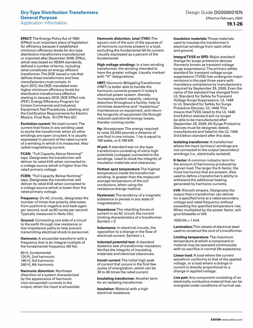
EPACT: The Energy Policy Act of 1992 (EPAct) is an important piece of legislation for efficiency because it established minimum efficiency levels for dry-type distribution transformers manufactured or imported after December 2006. EPAct, which was based on NEMA standards, defined a number of terms, including what constitutes an energy-efficient transformer. The DOE issued a rule that defines these transformers and how manufacturers must comply. In April 2013, the DOE mandated even higher minimum efficiency levels for distribution transformers effective starting in January 2016. DOE EPAct rule (PDF): Energy Efficiency Program for Certain Commercial and Industrial Equipment: Test Procedures, Labeling, and the Certification Requirements for Electric Motors. Final Rule. 10-CFR Part 431.
Excitation current: No load current. The current that flows in any winding used to excite the transformer when all other windings are open-circuited. It is usually expressed in percent of the rated current of a winding in which it is measured. Also called magnetizing current.
FCAN: “Full Capacity Above Nominal” taps. Designates the transformer will deliver its rated kVA when connected to a voltage source which is higher than the rated primary voltage.
FCBN: “Full Capacity Below Nominal” taps. Designates the transformer will deliver its rated kVA when connected to a voltage source which is lower than the rated primary voltage.
Frequency: On AC circuits, designates the number of times that polarity alternates from positive to negative and back again per second, such as 60 cycles per second. Typically measured in Hertz (Hz).
Ground: Connecting one side of a circuit to the earth through low resistance or low impedance paths to help prevent transmitting electrical shock to personnel.
Harmonic: A sinusoidal waveform with a frequency that is an integral multiple of the fundamental frequency (60 Hz).
60 H3 fundamental 120 H3 2nd harmonic 180 H3 3rd harmonic 240 H3 4th harmonic
Harmonic distortion: Nonlinear distortion of a system characterized by the appearance of harmonic (non-sinusoidal) currents in the output, when the input is sinusoidal.
Harmonic distortion, total (THD): The square root of the sum of the squares of all harmonic currents present in a load, excluding the fundamental 60 Hz current. Usually expressed as a percent of the fundamental.
High-voltage windings: In a two-winding transformer, the winding intended to have the greater voltage. Usually marked with “H” designations.
HMT: Harmonic Mitigating Transformer (HMT) is better able to handle the harmonic currents present in today’s electrical power system. thereby increasing system capacity, reducing distortion throughout a facility, help to minimize downtime and “mysterious” maintenance on equipment, and return the longevity of equipment life through reduced operational energy losses, thereby running cooler.
Hp: Horsepower. The energy required to raise 33,000 pounds a distance of one foot in one minute. 1 hp is equal to 746 watts, or 0.746 kW.
Hi pot: A standard test on dry-type transformers consisting of extra-high potentials (voltages) connected to the windings. Used to check the integrity of insulation materials and clearances.
Hottest-spot temperature: The high est temperature inside the transformer winding. Is greater than the measured average temperature of the coil conductors, when using the resistance change method.
Hysteresis: The tendency of a magnetic substance to persist in any state of magnetization.
Impedance: The retarding forces of current in an AC circuit; the current-limiting characteristics of a transformer. Symbol = Z
Inductance: In electrical circuits, the opposition to a change in the flow of electrical current. Symbol = L
Inducted potential test: A standard dielectric test of transformer insulation. Verifies the integrity of insulating materials and electrical clearances.
Inrush current: The initial high peak of current that occurs in the first few cycles of energization, which can be 30 to 40 times the rated current.
Insulating transformer: Another term for an isolating transformer.
Insulation: Material with a high electrical resistance.
Insulation materials: Those materials used to insulate the transformer’s electrical windings from each other and ground.
Integral TVSS or SPD: Major standard change for surge protective devices (formerly known as transient voltage surge suppressors). The primary safety standard for transient voltage surge suppressors (TVSS) has under gone major revisions in the past three years with mandatory compli ance by manufacturers required by September 29, 2009. Even the name of the standard has changed from UL Standard for Safety for Transient Voltage Surge Suppressors, UL 1449 to UL Standard for Safety for Surge Protective Devices, UL 1449. This means that TVSS listed to the UL 1449 2nd Edition standard will no longer be able to be manufactured after September 29, 2009. All Surge Protective Devices must be designed, tested, manufactured and listed to the UL 1449 3rd Edition standard after this date.
Isolating transformer: A transformer where the input (primary) windings are not connected to the output (secondary) windings (i.e., electrically isolated).
K-factor: A common industry term for the amount of harmonics produced by a given load. The larger the K-factor, the more harmonics that are present. Also used to define a transformer’s abil ity to withstand the additional heating generated by harmonic currents.
kVA: Kilovolt-ampere. Designates the output that a transformer can deliver for a specified time at a rated secondary voltage and rated frequency without exceeding the specified temperature rise. When multiplied by the power factor, will give kilowatts or kW.
1000 VA = 1 kVA
Lamination: Thin sheets of electrical steel used to construct the core of a transformer.
Limiting temperature: The maximum temperature at which a component or material may be operated continuously with no sacrifice in normal life expectancy.
Linear load: A load where the current waveform conforms to that of the applied voltage, or a load where a change in current is directly proportional to a change in applied voltage.
Live part: Any component consisting of an electrically conductive material that can be energized under conditions of normal use.
Design Guide DG009001EN Effective February 2020
19 .1-26
Dry-Type Distribution TransformersGeneral PurposeApplication Information
EATON www.eaton.com
Load losses: I2R losses in windings. Also see conductor losses.
Low-voltage winding: In a two-winding transformer, the winding intended to have the lesser voltage. Usually marked with “X” designations.
Mid-tap: See center tap.
Noise level: The relative intensity of sound, measured in decibels (dB). NEMA Standard ST-20 outlines the maximum allowable noise level for dry-type transformers.
Nonlinear load: A load where the current waveform does not conform to that of the applied voltage, or where a change in current is not proportional to a change in applied voltage.
Non-ventilated transformer: A transformer where the core and coil assembly is mounted inside an enclosure with no openings for ventilation. Also referred to as totally enclosed non-ventilated (TENV).
No load losses: Losses in a transformer that is excited at rated voltage and frequency but that is not supplying a load. No load losses include core losses, dielectric losses and conductor losses in the winding due to the exciting current. Also referred to as excitation losses.
Overload capability: Short-term overload capacity is designed into transformers as required by ANSI. Continuous overload capacity is not deliberately designed into a transformer because the design objective is to be within the allowed winding temperature rise with nameplate loading.
Percent IR (% resistance): Voltage drop due to resistance at rated current in percent of rated voltage.
Percent IX (% reactance): Voltage drop due to reactance at rated current in percent of rated voltage.
Percent IZ (% impedance): Voltage drop due to impedance at rated current in percent of rated voltage.
Phase: Type of AC electrical circuit; usually single-phase two- or three-wire, or three-phase three- or four-wire.
Polarity test: A standard test on transformers to determine instantaneous direction of the voltages in the primary compared to the secondary.
Primary taps: Taps added to the primary (input) winding. See Tap.
Primary voltage: The input circuit voltage.
Power factor: The cosine of the phase angle between a voltage and a current.
Ratio test: A standard test of transformers to determine the ratio of the input (primary) voltage to the output (secondary) voltage.
Reactance: The effect of inductive and capacitive components of a circuit producing other than unity power factor.
Reactor: A single winding device with an air or iron core that produces a specific amount of inductive reactance into a circuit. Normally used to reduce of control current.
Regulation: Usually expressed as the percent change in output voltage when the load goes from full load to no load.
Scott T connection: Connection for three-phase transformers. Instead of using three sets of coils for a three-phase load, the transformer uses only two sets of coils.
Series/multiple winding: A winding consisting of two or more sections that can be connected for series operation or multiple (parallel) operation. Also called series-parallel winding.
Short circuit: A low resistance connection, usually accidental, across part of a circuit, resulting in excessive current flow.
Sound levels: All transformers make some sound mainly due to the vibration generated in its core by alternating flux. All Eaton general-purpose dry-type distribution transformers are designed with sound levels lower than NEMA ST-20 maximum levels.
Star connection: Same as a wye connection.
Step-down transformer: A trans former where the input voltage is greater than the output voltage.
Step-up transformer: A transformer where the input voltage is less than the output voltage.
T-T connection: See Scott T connection.
Tap: A connection brought out of a winding at some point between its extremities, usually to permit changing the voltage or current ratio. Taps are typically used to compensate for above or below rated input voltage, in order to provide the rated output voltage. See FCAN and FCBN.
Temperature class: The maximum tem perature that the insulation system of a transformer can continuously with stand. The common insulation classes are 105, 150, 180 (also 185) and 220.
Temperature rise: The increase over ambient temperature of the windings due to energizing and loading the transformer.
Total losses: The sum of the no-load losses and load losses.
Totally enclosed non-ventilated enclosure: The core and coil assembly is installed inside an enclosure that has no ventilation to cool the transformer. The transformer relies on heat to radiate from the enclosure for cooling.
Transformer tests: Per NEMA ST-20, routine transformer production tests are performed on each transformer prior to shipment. These tests are: Ratio tests on the rated voltage connection; Polarity and Phase Relation tests on the rated connection; No-Load and Excitation Current tests at rated voltage on the rated voltage connection and Applied Potential and Induced Potential tests. Special tests include sound level testing.
Transverse mode: Electrical noise or voltage disturbance that occurs between phase and neutral, or from spurious signals across metallic hot line and the neutral conductor.
Turns ratio: The ratio of the number of turns in the high voltage winding to that in the low voltage winding.
Typical test data: Tests that were performed on similar units that were previously manufactured and tested.
UL (Underwriters Laboratories): An independent safety testing organization.
Universal taps: A combination of six primary voltage taps consisting of 2 at +2-1/2% FCAN and 4 at -2-1/2% FCBN.
Watt: A unit of electrical power when the current in a circuit is one ampere and the voltage is one volt.
Wye connection: A standard three-wire transformer connection with similar ends of single-phase coils connected together. The common point forms the electrical neutral point and may be grounded. Also referred to as three-phase four-wire. To obtain the line-to-neutral voltage, divide the line voltage by (1.732).
Design Guide DG009001EN Effective February 2020
19 .1-27
Dry-Type Distribution TransformersGeneral PurposeApplication Information
EATON www.eaton.com
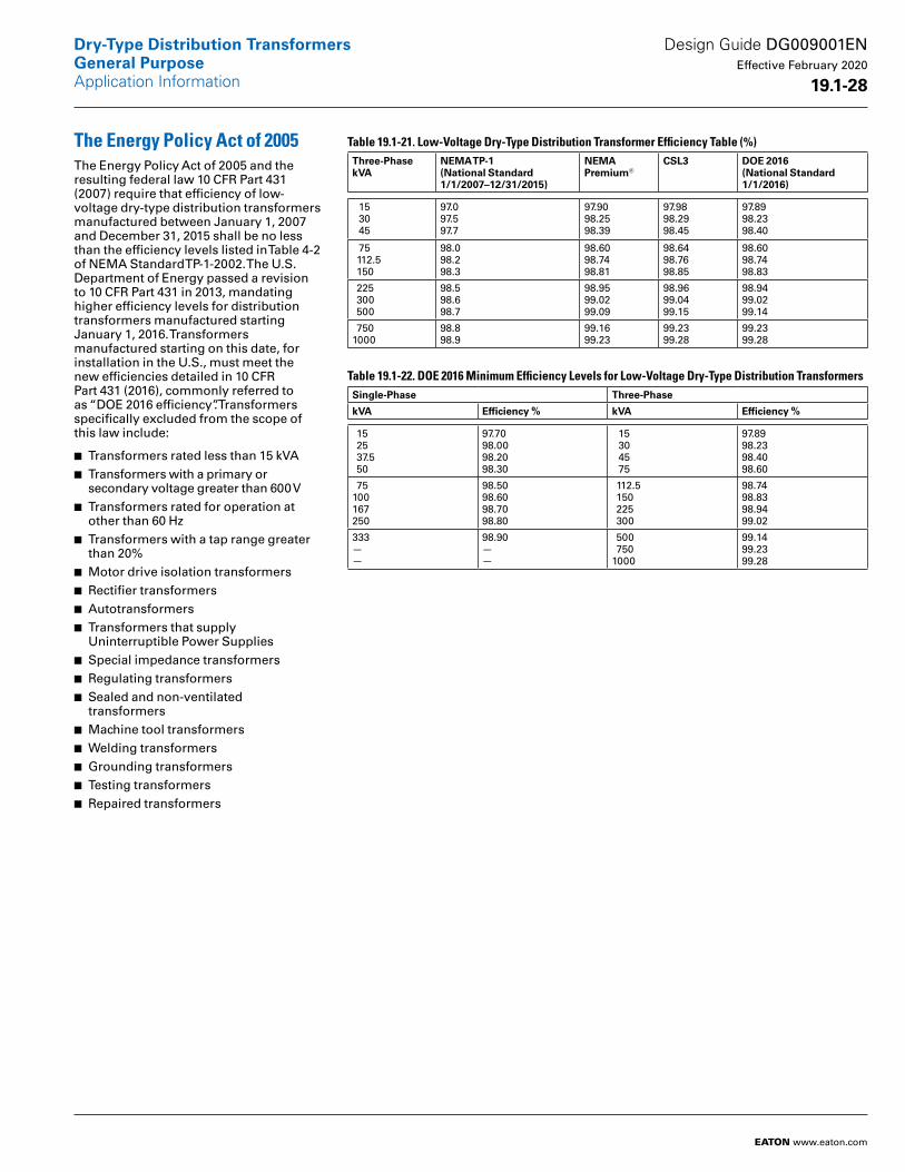
The Energy Policy Act of 2005The Energy Policy Act of 2005 and the resulting federal law 10 CFR Part 431 (2007) require that efficiency of low-voltage dry-type distribution transformers manufactured between January 1, 2007 and December 31, 2015 shall be no less than the efficiency levels listed in Table 4-2 of NEMA Standard TP-1-2002. The U.S. Department of Energy passed a revision to 10 CFR Part 431 in 2013, mandating higher efficiency levels for distribution transformers manufactured starting January 1, 2016. Transformers manufactured starting on this date, for installation in the U.S., must meet the new efficiencies detailed in 10 CFR Part 431 (2016), commonly referred to as “DOE 2016 efficiency”. Transformers specifically excluded from the scope of this law include:
■ Transformers rated less than 15 kVA■ Transformers with a primary or secondary voltage greater than 600 V
■ Transformers rated for operation at other than 60 Hz
■ Transformers with a tap range greater than 20%
■ Motor drive isolation transformers■ Rectifier transformers■ Autotransformers■ Transformers that supply Uninterruptible Power Supplies
■ Special impedance transformers■ Regulating transformers■ Sealed and non-ventilated transformers
■ Machine tool transformers■ Welding transformers■ Grounding transformers■ Testing transformers■ Repaired transformers
Table 19.1-21. Low-Voltage Dry-Type Distribution Transformer Efficiency Table (%)Three-PhasekVA
NEMA TP-1 (National Standard 1/1/2007–12/31/2015)
NEMA Premium®
CSL3 DOE 2016(National Standard 1/1/2016)
15 30 45
97.097.597.7
97.9098.2598.39
97.9898.2998.45
97.8998.2398.40
75 112.5 150
98.098.298.3
98.6098.7498.81
98.6498.7698.85
98.6098.7498.83
225 300 500
98.598.698.7
98.9599.0299.09
98.9699.0499.15
98.9499.0299.14
7501000
98.898.9
99.1699.23
99.2399.28
99.2399.28
Table 19.1-22. DOE 2016 Minimum Efficiency Levels for Low-Voltage Dry-Type Distribution TransformersSingle-Phase Three-Phase
kVA Efficiency % kVA Efficiency %
15 25 37.5 50
97.7098.0098.2098.30
15 30 45 75
97.8998.2398.4098.60
75100167250
98.5098.6098.7098.80
112.5 150 225 300
98.7498.8398.9499.02
333——
98.90——
500 7501000
99.1499.2399.28
Design Guide DG009001EN Effective February 2020
19 .1-28
Dry-Type Distribution TransformersGeneral PurposeApplication Information
EATON www.eaton.com
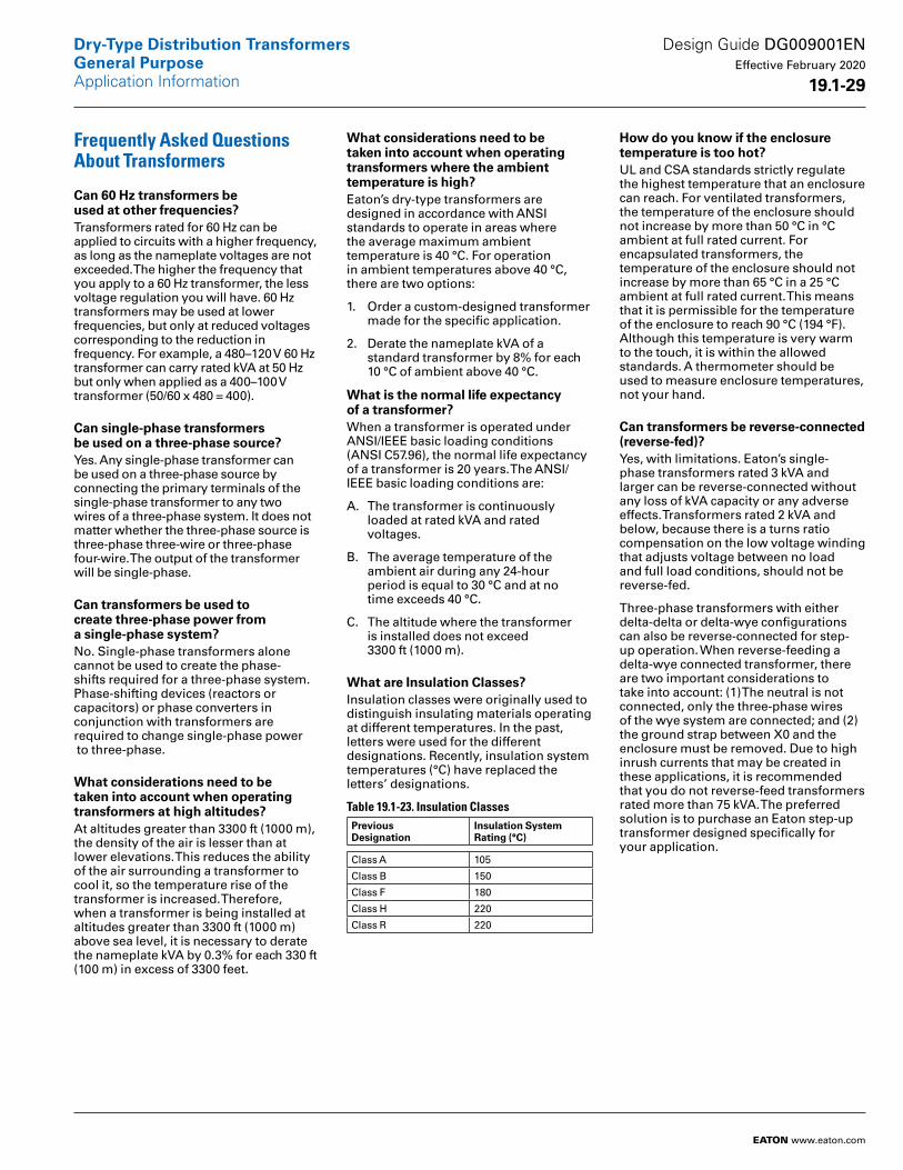
Frequently Asked Questions About Transformers
Can 60 Hz transformers be used at other frequencies?Transformers rated for 60 Hz can be applied to circuits with a higher frequency, as long as the nameplate voltages are not exceeded. The higher the frequency that you apply to a 60 Hz transformer, the less voltage regulation you will have. 60 Hz transformers may be used at lower frequencies, but only at reduced voltages corresponding to the reduction in frequency. For example, a 480–120 V 60 Hz transformer can carry rated kVA at 50 Hz but only when applied as a 400–100 V transformer (50/60 x 480 = 400).
Can single-phase transformers be used on a three-phase source?Yes. Any single-phase transformer can be used on a three-phase source by connecting the primary terminals of the single-phase transformer to any two wires of a three-phase system. It does not matter whether the three-phase source is three-phase three-wire or three-phase four-wire. The output of the transformer will be single-phase.
Can transformers be used to create three-phase power from a single-phase system?No. Single-phase transformers alone cannot be used to create the phase- shifts required for a three-phase system. Phase-shifting devices (reactors or capacitors) or phase converters in conjunction with transformers are required to change single-phase power to three-phase.
What considerations need to be taken into account when operating transformers at high altitudes?At altitudes greater than 3300 ft (1000 m), the density of the air is lesser than at lower elevations. This reduces the ability of the air surrounding a transformer to cool it, so the temperature rise of the transformer is increased. Therefore, when a transformer is being installed at altitudes greater than 3300 ft (1000 m) above sea level, it is necessary to derate the nameplate kVA by 0.3% for each 330 ft (100 m) in excess of 3300 feet.
What considerations need to be taken into account when operating transformers where the ambient temperature is high?Eaton’s dry-type transformers are designed in accordance with ANSI standards to operate in areas where the average maximum ambient temperature is 40 °C. For operation in ambient temperatures above 40 °C, there are two options:
1. Order a custom-designed transformer made for the specific application.
2. Derate the nameplate kVA of a standard transformer by 8% for each 10 °C of ambient above 40 °C.
What is the normal life expectancy of a transformer?When a transformer is operated under ANSI/IEEE basic loading conditions (ANSI C57.96), the normal life expectancy of a trans former is 20 years. The ANSI/IEEE basic loading conditions are:
A. The transformer is continuously loaded at rated kVA and rated voltages.
B. The average temperature of the ambient air during any 24-hour period is equal to 30 °C and at no time exceeds 40 °C.
C. The altitude where the transformer is installed does not exceed 3300 ft (1000 m).
What are Insulation Classes?Insulation classes were originally used to distinguish insulating materials operating at different temperatures. In the past, letters were used for the different designations. Recently, insulation system temperatures (°C) have replaced the letters’ designations.
Table 19.1-23. Insulation Classes PreviousDesignation
Insulation SystemRating (°C)
Class A 105
Class B 150
Class F 180
Class H 220
Class R 220
How do you know if the enclosure temperature is too hot?UL and CSA standards strictly regulate the highest tempera ture that an enclosure can reach. For ventilated transformers, the temperature of the enclosure should not increase by more than 50 °C in °C ambient at full rated current. For encapsulated transformers, the temperature of the enclosure should not increase by more than 65 °C in a 25 °C ambient at full rated current. This means that it is permissible for the temperature of the enclosure to reach 90 °C (194 °F). Although this temper ature is very warm to the touch, it is within the allowed stan dards. A thermometer should be used to measure enclosure temperatures, not your hand.
Can transformers be reverse-connected (reverse-fed)?Yes, with limitations. Eaton’s single- phase transformers rated 3 kVA and larger can be reverse-connected without any loss of kVA capacity or any adverse effects. Transformers rated 2 kVA and below, because there is a turns ratio compensation on the low voltage winding that adjusts voltage between no load and full load conditions, should not be reverse-fed.
Three-phase transformers with either delta-delta or delta-wye configurations can also be reverse-connected for step- up operation. When reverse-feeding a delta-wye connected transformer, there are two important considerations to take into account: (1) The neutral is not connected, only the three-phase wires of the wye system are connected; and (2) the ground strap between X0 and the enclosure must be removed. Due to high inrush currents that may be created in these applications, it is recommended that you do not reverse-feed transformers rated more than 75 kVA. The preferred solution is to purchase an Eaton step-up transformer designed specifically for your application.
Design Guide DG009001EN Effective February 2020
19 .1-29
Dry-Type Distribution TransformersGeneral PurposeApplication Information
EATON www.eaton.com
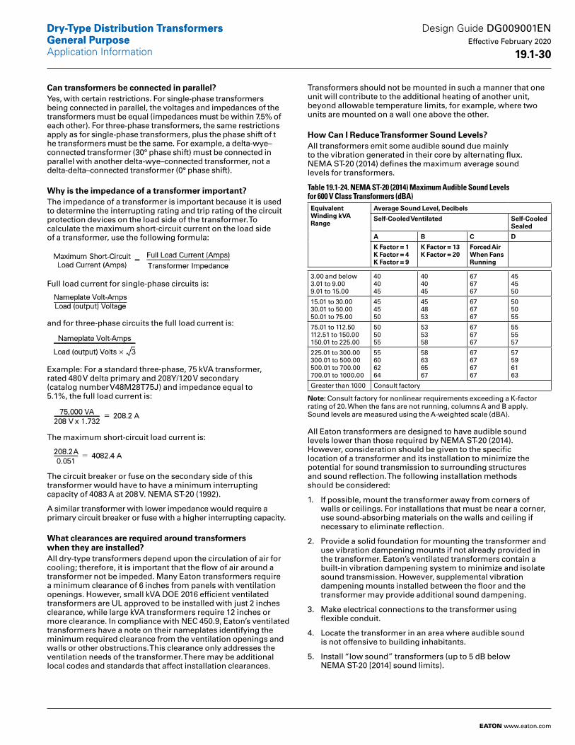
Can transformers be connected in parallel?Yes, with certain restrictions. For single-phase transformers being connected in parallel, the voltages and impedances of the transformers must be equal (impedances must be within 7.5% of each other). For three-phase transformers, the same restrictions apply as for single-phase transformers, plus the phase shift of t he transformers must be the same. For example, a delta-wye–connected transformer (30° phase shift) must be connected in parallel with another delta-wye–connected transformer, not a delta-delta–connected transformer (0° phase shift).
Why is the impedance of a transformer important?The impedance of a transformer is important because it is used to determine the interrupting rating and trip rating of the circuit protection devices on the load side of the trans former. To calculate the maximum short-circuit current on the load side of a transformer, use the following formula:
Full load current for single-phase circuits is:
and for three-phase circuits the full load current is:
Example: For a standard three-phase, 75 kVA transformer, rated 480 V delta primary and 208Y/120 V secondary (catalog number V48M28T75J) and impedance equal to 5.1%, the full load current is:
The maximum short-circuit load current is:
The circuit breaker or fuse on the secondary side of this transformer would have to have a minimum interrupting capacity of 4083 A at 208 V. NEMA ST-20 (1992).
A similar transformer with lower impedance would require a primary circuit breaker or fuse with a higher interrupting capacity.
What clearances are required around transformers when they are installed?All dry-type transformers depend upon the circulation of air for cooling; therefore, it is important that the flow of air around a transformer not be impeded. Many Eaton transformers require a minimum clearance of 6 inches from panels with ventilation openings. However, small kVA DOE 2016 efficient ventilated transformers are UL approved to be installed with just 2 inches clearance, while large kVA transformers require 12 inches or more clearance. In compliance with NEC 450.9, Eaton’s ventilated transformers have a note on their nameplates identifying the minimum required clearance from the ventilation openings and walls or other obstructions. This clearance only addresses the ventilation needs of the transformer. There may be additional local codes and standards that affect installation clearances.
Transformers should not be mounted in such a manner that one unit will contribute to the additional heating of another unit, beyond allowable temperature limits, for example, where two units are mounted on a wall one above the other.
How Can I Reduce Transformer Sound Levels?All transformers emit some audible sound due mainly to the vibration generated in their core by alternating flux. NEMA ST-20 (2014) defines the maximum average sound levels for transformers.
Table 19.1-24. NEMA ST-20 (2014) Maximum Audible Sound Levels for 600 V Class Transformers (dBA)Equivalent Winding kVA Range
Average Sound Level, Decibels
Self-Cooled Ventilated Self-Cooled Sealed
A B C D
K Factor = 1K Factor = 4K Factor = 9
K Factor = 13K Factor = 20
Forced Air When Fans Running
3.00 and below3.01 to 9.009.01 to 15.00
404045
404045
676767
454550
15.01 to 30.0030.01 to 50.0050.01 to 75.00
454550
454853
676767
505055
75.01 to 112.50112.51 to 150.00150.01 to 225.00
505055
535358
676767
555557
225.01 to 300.00300.01 to 500.00500.01 to 700.00700.01 to 1000.00
55606264
58636567
67676767
57596163
Greater than 1000 Consult factory
Note: Consult factory for nonlinear requirements exceeding a K-factor rating of 20. When the fans are not running, columns A and B apply. Sound levels are measured using the A-weighted scale (dBA).
All Eaton transformers are designed to have audible sound levels lower than those required by NEMA ST-20 (2014). However, consideration should be given to the specific location of a transformer and its installation to minimize the potential for sound transmission to surrounding structures and sound reflection. The following installation methods should be considered:
1. If possible, mount the transformer away from corners of walls or ceilings. For installations that must be near a corner, use sound-absorbing materials on the walls and ceiling if necessary to eliminate reflection.
2. Provide a solid foundation for mounting the transformer and use vibration dampening mounts if not already provided in the transformer. Eaton’s ventilated trans formers contain a built-in vibration dampening system to minimize and isolate sound transmission. However, supplemental vibration dampening mounts installed between the floor and the transformer may provide additional sound dampening.
3. Make electrical connections to the transformer using flexible conduit.
4. Locate the transformer in an area where audible sound is not offensive to building inhabitants.
5. Install “low sound” transformers (up to 5 dB below NEMA ST-20 [2014] sound limits).
Design Guide DG009001EN Effective February 2020
19 .1-30
Dry-Type Distribution TransformersGeneral PurposeApplication Information
EATON www.eaton.com
Dry-Type Distribution TransformersGeneral Purpose
Eaton1000 Eaton BoulevardCleveland, OH 44122United StatesEaton .com
© 2020 EatonAll Rights ReservedPrinted in USAPublication No . DG009001EN / Z23483February 2020
Eaton is a registered trademark.
All other trademarks are property of their respective owners.
Dry-Type Distribution TransformersGeneral Purpose
Design Guide DG009001EN Effective February 2020
19 .1-31