Embed Size (px)
Citation preview
ORIGINAL PAPER
Dry Sliding Wear Behavior of Zircon Sand Reinforced Al–Si Alloy
Kamalpreet Kaur • O. P. Pandey
Received: 20 January 2010 / Accepted: 3 May 2010 / Published online: 19 May 2010
� Springer Science+Business Media, LLC 2010
Abstract The emerging demand of light weight alloys and
composites for the engineering and structural applications
leads to explore the possibility to develop new techniques to
achieve materials of high performance. In the present study,
Al–Si/zircon sand reinforced composite has been developed
via spray forming technique. Dry sliding wear behavior of as
cast Al–Si base alloy and spray formed Al–Si/zircon sand
reinforced composite containing 8% Vf of zircon sand has
been analyzed. An isotropic wear property of spray formed
composite has been checked by selecting the spray formed
preform in both horizontal and vertical sections of deposit.
The wear tests which were carried out at loads of 14.7, 24.5,
34.3, 44.1, and 53.9 N have shown that spray formed
composite is more wear resistant in comparison to the cast
Al–Si alloy. Moreover, wear coefficient in case of com-
posite is also found to be lower than base alloy. Optical and
scanning electron microscopies have been carried out to
furnish a suitable explanation for observed wear behavior of
composite and alloy.
Keywords Adhesive wear � Wear mechanisms �SEM � Wear particle analysis
1 Introduction
In the last few decades, aluminum metal matrix com-
posites (AMCs) have drawn considerable attention as fuel
efficient advance materials for tribological applications.
The desirable mechanical properties can be achieved by
varying the reinforcing materials and their volume frac-
tion in the composite. Many processing techniques have
been developed successfully to manufacture metal matrix
composites (stir casting, die-casting, and powder metal-
lurgy) on the commercial scale. Among these spray
forming combines the benefits of microstructural refine-
ment and alloying flexibility. Spray forming is one of the
non-equilibrium processing techniques, in which micro-
structure is refined by rapid solidification effects. The
choice of processing technique for AMCs is very impor-
tant. The study of cast aluminum containing particles
Al2O3 and SiC showed settling of particulates in the sand
mold [1]. However, this can be eliminated in spray
forming process. It is a near net-shape processing tech-
nique combining atomization and deposition of liquid
melt in single step, whereas the other P/M and ingot
metallurgy routes contain large number of processing
steps. Hence, the spray forming reduces the number of
secondary processes and thus resulting in reduction in the
cost of the product [2].
Spray forming was initially proposed by Singer [3] at
University College Swansea, and nowadays it has got
industrial attraction for conventional alloys as well as
advanced high performance composites. The microstruc-
tural refinement and uniformity in distribution of rein-
forcement in the matrix depend upon melt superheat,
nozzle to substrate distance, metal to gas flow rate and high
heat removal rate at the droplet–gas interface [4, 5]. Further
microstructural refinement and reduction in porosity can be
achieved by using spray rolling [6], low pressure spray
forming [7], and secondary processes like hot rolling or
extrusion [2]. Tensile tests at the ambient and elevated
temperatures reveal that spray processed Al–Si alloys have
K. Kaur � O. P. Pandey (&)
School of Physics and Materials Science, Thapar University,
Patiala 147 004, Punjab, India
e-mail: [email protected]
K. Kaur
e-mail: [email protected]
123
Tribol Lett (2010) 38:377–387
DOI 10.1007/s11249-010-9620-6
better strength and ductility than processed by conventional
ingot metallurgy route [8–10].
The nature of wear is highly influenced by the method of
processing, size, type, and amount of ceramic reinforce-
ment. Moreover, hard particulates in the soft metallic matrix
help to reduce wear loss in comparison to base soft metal. A
lot of literature is available on the reinforcement of various
particles (SiC, Al2O3, TiO2, TiB2, etc.) in spray deposited
composites, which give better physical and mechanical
properties as compare to their cast counterparts [11, 12].
Also the spray deposition process has the potential to pro-
duce large particulate-reinforced MMC ingot. The SiCp
reinforced AMC up to 15% volume fraction (Vf) showed the
uniform distribution of particles with good bonding between
particle–matrix interface in the high density matrix with low
segregation of SiCp [13]. Similarly, spray processed and hot
extruded AA7475 with 20% Vf of SiC billets showed Mg2Si
precipitation at the matrix–particle interface [14]. Pai et al.
[15] found that Mg improves wetting of dispersoid by
increasing its surface reactivity and decreasing the solid/
liquid interfacial energy at the dispersoid matrix interface.
Addition of SiC in 2014Al alloy gave rise to considerable
improvement in wear resistance [16]. The wear resistance of
spray processed Al–Si/SiCp composite can be further
enhanced by thermomechanical treatment and with
increasing Si content [17].
Recently, AMCs reinforced with zircon sand has been
found to be more economical and suitable AMC because of
higher fracture toughness of zircon than SiC. Zircon having
good hardness, modulus of elasticity, and excellent thermal
stability, is being studied for AMCs where contacting parts
operate in relative motions. Banerji et al. [18] in Al–11.8
Si–3 Mg system dispersed 25–30% zircon particles by
stirring and N2 degassing. The process of pressure die-
casting is required as the fluidity of melt decreases above
30%. Moreover, with dispersion of zircon particles in
Al–3% Mg alloy hardness, abrasive wear test, elastic
modulus, 0.2% proof stress, and tensile tests were
improved. Ejiofor et al. [19] made an attempt to manu-
facture low-cost double compaction P/M route in zircon
reinforced Al–13.5 Si–2.5 Mg alloy. Their structure anal-
ysis showed significant improvement in mechanical and
load bearing properties, which is attributed due to intrinsic
hardness of zircon as particulate-reinforced effect.
Similarly, Jangg et al. [20] produced lightweight and
higher wear resistant Al camshaft belt pulleys for engines
from standard Al powder mixtures with the addition of 10
mass% of ZrSiO4 by pressing, sintering at optimized
parameters and sizing. Both dimensional and wear prop-
erties were found to be comparable to those of conven-
tional iron pulleys. Abrasive wear of Al–4.5% Cu matrix
reinforced with Al2O3 and ZrSiO4 particulate showed that
wear resistance property of the composite increases with
the decrease in the particle size [21]. Furthermore, the
zircon reinforced composite showed high resistance to
wear in comparison to the alumina reinforced composite
[21].
The present work is focused on the spray deposition
processing of zircon sand reinforced near eutectic Al–Si
piston alloy and its tribological application. Earlier work
on stir cast zircon sand reinforced Al–Cu alloy composite
is available in literature [21]. The tribological applicability
has been explored with wear test of base alloy and com-
posite in light of microstructural features of worn pin
surfaces and debris.
2 Experimental Procedure
The Al–Si/zircon sand composite has been prepared by the
spray atomization and co-deposition process. The obtained
Al–Si alloy composition was analyzed by wet chemical
analysis and X-ray florescence technique as shown in
Table 1. The spray atomization apparatus consists of four
major units, i.e., melting furnace, atomization zone,
injector assembly, and deposition surface [22]. For spray
forming, the Al–Si alloy is melted in a graphite crucible in
a muffle furnace at 750 �C. After cooling the melt to
700 �C, it is poured in the convergent divergent nozzle
assembly. Before pouring high pressure nitrogen gas is
allowed to pass through the divergent section of the nozzle.
The aerodynamic forces exerted by high velocity nitrogen
gas jets atomize the molten metal stream into fine droplets.
The parameters used for spray atomization are shown in
Table 2. Injectors are used to incorporate zircon sand
particles in the spray cone. Several interactions do take
place in the atomization zone that includes the gas–liquid
interaction, formation of micron sized droplets, droplet–
droplet collisions, and droplet–particulate collisions. The
zircon sand particles are released in the atomizing zone
near the melt delivery tube. These injected particles pos-
sess sufficient kinetic energy and droplet–particle collision
Table 1 Composition of Al–Si alloy
Alloy Si Fe Cu Mn Mg Zn Ti Ni Pb Sn Al
XRF 11.166 0.332 1.247 0.598 0.849 0.250 0.026 0.868 0.001 0.002 Balance
Chemical analysis 11.800 0.365 1.230 0.411 0.940 0.210 0.0254 0.940 0.0289 0.005 Balance
378 Tribol Lett (2010) 38:377–387
123
occurs in the beginning of the atomizing zone which may
give rise to penetration of the particles inside the droplet.
The droplets get solidified and build up preform of diam-
eter 150 mm. For wear testing, the samples were cut from
different areas of the preform. The X-ray diffraction pat-
terns of the prepared sample was recorded on Panalytical
X’pert Pro MPD, Netherland using Cu Ka radiation
(k = 1.54 A). The collected data were matched with ref-
erence data for identification of different phases.
Dry sliding wear tests of the reinforced and unreinforced
alloys have been performed under the ambient tempera-
tures between 25–30 �C and relative humidity between 25–
42%, using a pin-on-disc wear and friction monitor (Model
TR-20, Ducom, Bangalore). The cylindrical shaped sam-
ples (25 9 9 mm) of base Al–Si alloy, spray formed Al–
Si/zircon sand composite sectioned vertically and hori-
zontally were tested against the hardened EN32 steel disc
having chemical composition (0.14% C, 0.52% Mn, 0.18%
Si, 0.13% Ni, 0.05% Cr, 0.06% Mo, 0.019% P, 0.015% S,
balance Fe) and hardness 65 HRC. Before testing, each
specimen is ultrasonically cleaned in acetone. Wear rate
has been calculated by measuring weight loss at different
time intervals. Archimedes’s principle is used to measure
the density of both reinforced and unreinforced material.
The wear tests of one specimen from each set have been
conducted up to 2,880 m run at a constant sliding velocity
of 1.6 m s-1 and under five different loads 14.7, 24.5, 34.3,
44.1, and 53.9 N for both reinforced and unreinforced
alloy. The scanning electron microscope and EDS (SEM
Quanta, 200 FEG, FEI Netherland) is used for micro-
structural examination of specimen, analyzing worn sur-
faces, and debris collected during the test.
3 Results and Discussion
3.1 XRD and Microstructure
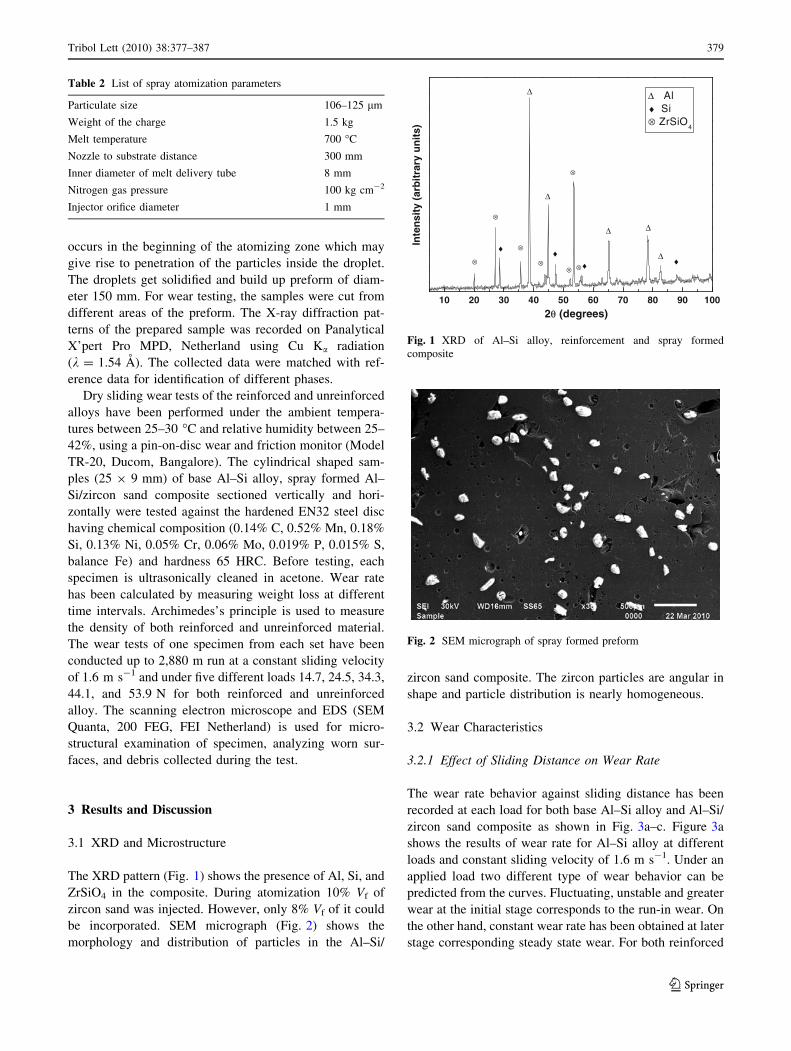
The XRD pattern (Fig. 1) shows the presence of Al, Si, and
ZrSiO4 in the composite. During atomization 10% Vf of
zircon sand was injected. However, only 8% Vf of it could
be incorporated. SEM micrograph (Fig. 2) shows the
morphology and distribution of particles in the Al–Si/
zircon sand composite. The zircon particles are angular in
shape and particle distribution is nearly homogeneous.
3.2 Wear Characteristics
3.2.1 Effect of Sliding Distance on Wear Rate
The wear rate behavior against sliding distance has been
recorded at each load for both base Al–Si alloy and Al–Si/
zircon sand composite as shown in Fig. 3a–c. Figure 3a
shows the results of wear rate for Al–Si alloy at different
loads and constant sliding velocity of 1.6 m s-1. Under an
applied load two different type of wear behavior can be
predicted from the curves. Fluctuating, unstable and greater
wear at the initial stage corresponds to the run-in wear. On
the other hand, constant wear rate has been obtained at later
stage corresponding steady state wear. For both reinforced
Table 2 List of spray atomization parameters
Particulate size 106–125 lm
Weight of the charge 1.5 kg
Melt temperature 700 �C
Nozzle to substrate distance 300 mm
Inner diameter of melt delivery tube 8 mm
Nitrogen gas pressure 100 kg cm-2
Injector orifice diameter 1 mm
10 20 30 40 50 60 70 80 90 100
Δ
Δ
Δ
Δ
Δ
♦♦♦♦
⊗ ⊗
⊗
⊗
⊗
⊗
⊗
Inte
nsi
ty (
arb
itra
ry u
nit
s)
2θ (degrees)
Δ Al♦ Si⊗ ZrSiO
4
Fig. 1 XRD of Al–Si alloy, reinforcement and spray formed
composite
Fig. 2 SEM micrograph of spray formed preform
Tribol Lett (2010) 38:377–387 379
123
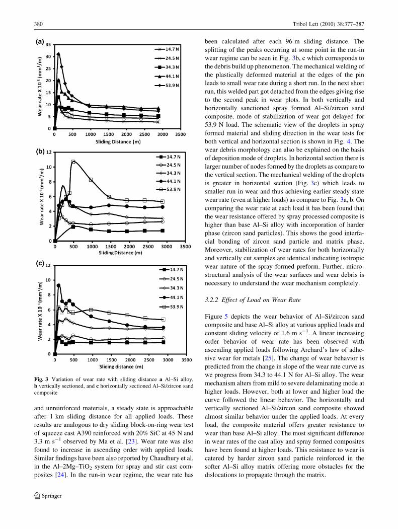
and unreinforced materials, a steady state is approachable
after 1 km sliding distance for all applied loads. These
results are analogous to dry sliding block-on-ring wear test
of squeeze cast A390 reinforced with 20% SiC at 45 N and
3.3 m s-1 observed by Ma et al. [23]. Wear rate was also
found to increase in ascending order with applied loads.
Similar findings have been also reported by Chaudhury et al.
in the Al–2Mg–TiO2 system for spray and stir cast com-
posites [24]. In the run-in wear regime, the wear rate has
been calculated after each 96 m sliding distance. The
splitting of the peaks occurring at some point in the run-in
wear regime can be seen in Fig. 3b, c which corresponds to
the debris build up phenomenon. The mechanical welding of
the plastically deformed material at the edges of the pin
leads to small wear rate during a short run. In the next short
run, this welded part got detached from the edges giving rise
to the second peak in wear plots. In both vertically and
horizontally sanctioned spray formed Al–Si/zircon sand
composite, mode of stabilization of wear got delayed for
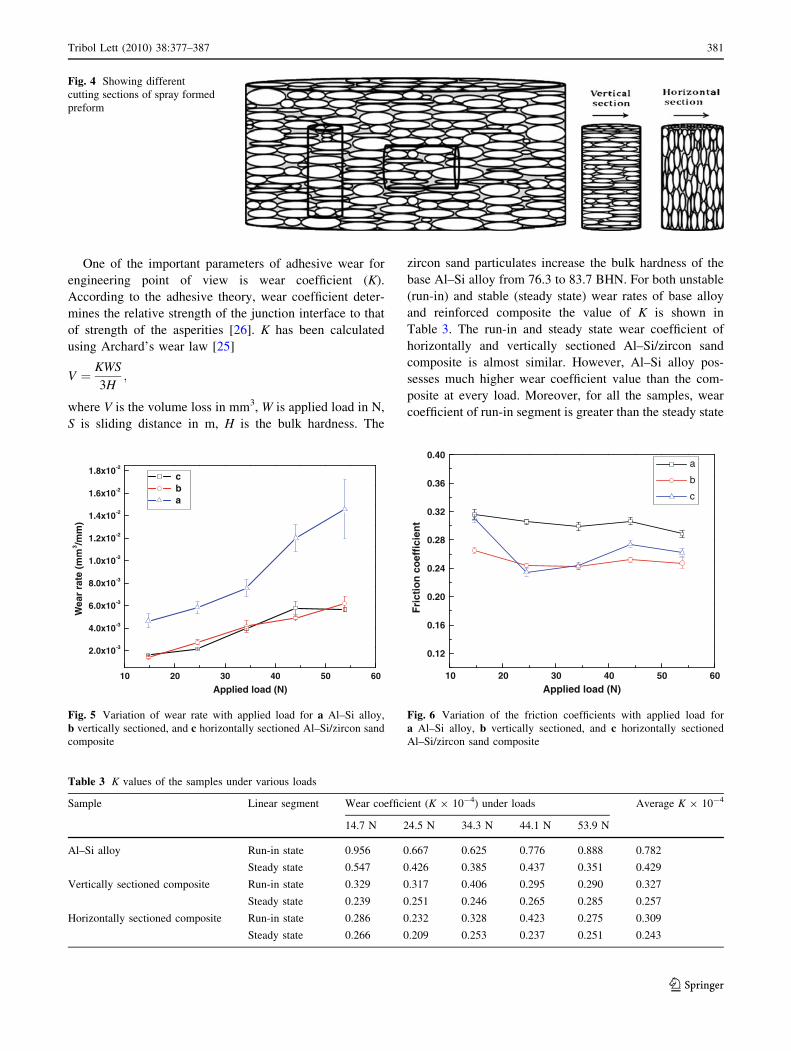
53.9 N load. The schematic view of the droplets in spray
formed material and sliding direction in the wear tests for
both vertical and horizontal section is shown in Fig. 4. The
wear debris morphology can also be explained on the basis
of deposition mode of droplets. In horizontal section there is
larger number of nodes formed by the droplets as compare to
the vertical section. The mechanical welding of the droplets
is greater in horizontal section (Fig. 3c) which leads to
smaller run-in wear and thus achieving earlier steady state
wear rate (even at higher loads) as compare to Fig. 3a, b. On
comparing the wear rate at each load it has been found that
the wear resistance offered by spray processed composite is
higher than base Al–Si alloy with incorporation of harder
phase (zircon sand particles). This shows the good interfa-
cial bonding of zircon sand particle and matrix phase.
Moreover, stabilization of wear rates for both horizontally
and vertically cut samples are identical indicating isotropic
wear nature of the spray formed preform. Further, micro-
structural analysis of the wear surfaces and wear debris is
necessary to understand the wear mechanism completely.
3.2.2 Effect of Load on Wear Rate
Figure 5 depicts the wear behavior of Al–Si/zircon sand
composite and base Al–Si alloy at various applied loads and
constant sliding velocity of 1.6 m s-1. A linear increasing
order behavior of wear rate has been observed with
ascending applied loads following Archard’s law of adhe-
sive wear for metals [25]. The change of wear behavior is
predicted from the change in slope of the wear rate curve as
we progress from 34.3 to 44.1 N for Al–Si alloy. The wear
mechanism alters from mild to severe delaminating mode at
higher loads. However, both at lower and higher load the
curve followed the linear behavior. The horizontally and
vertically sectioned Al–Si/zircon sand composite showed
almost similar behavior under the applied loads. At every
load, the composite material offers greater resistance to
wear than base Al–Si alloy. The most significant difference
in wear rates of the cast alloy and spray formed composites
have been found at higher loads. This resistance to wear is
catered by harder zircon sand particle reinforced in the
softer Al–Si alloy matrix offering more obstacles for the
dislocations to propagate through the matrix.
Fig. 3 Variation of wear rate with sliding distance a Al–Si alloy,
b vertically sectioned, and c horizontally sectioned Al–Si/zircon sand
composite
380 Tribol Lett (2010) 38:377–387
123
One of the important parameters of adhesive wear for
engineering point of view is wear coefficient (K).
According to the adhesive theory, wear coefficient deter-
mines the relative strength of the junction interface to that
of strength of the asperities [26]. K has been calculated
using Archard’s wear law [25]
V ¼ KWS
3H;
where V is the volume loss in mm3, W is applied load in N,
S is sliding distance in m, H is the bulk hardness. The
zircon sand particulates increase the bulk hardness of the
base Al–Si alloy from 76.3 to 83.7 BHN. For both unstable
(run-in) and stable (steady state) wear rates of base alloy
and reinforced composite the value of K is shown in
Table 3. The run-in and steady state wear coefficient of
horizontally and vertically sectioned Al–Si/zircon sand
composite is almost similar. However, Al–Si alloy pos-
sesses much higher wear coefficient value than the com-
posite at every load. Moreover, for all the samples, wear
coefficient of run-in segment is greater than the steady state
Fig. 4 Showing different
cutting sections of spray formed
preform
10 20 30 40 50 60
2.0x10⁻³
4.0x10⁻³
6.0x10⁻³
8.0x10⁻³
1.0x10⁻²
1.2x10⁻²
1.4x10⁻²
1.6x10⁻²
1.8x10⁻²
Wea
r ra
te (
mm
3 /mm
)
Applied load (N)
c b a
Fig. 5 Variation of wear rate with applied load for a Al–Si alloy,
b vertically sectioned, and c horizontally sectioned Al–Si/zircon sand
composite
Table 3 K values of the samples under various loads
Sample Linear segment Wear coefficient (K 9 10-4) under loads Average K 9 10-4
14.7 N 24.5 N 34.3 N 44.1 N 53.9 N
Al–Si alloy Run-in state 0.956 0.667 0.625 0.776 0.888 0.782
Steady state 0.547 0.426 0.385 0.437 0.351 0.429
Vertically sectioned composite Run-in state 0.329 0.317 0.406 0.295 0.290 0.327
Steady state 0.239 0.251 0.246 0.265 0.285 0.257
Horizontally sectioned composite Run-in state 0.286 0.232 0.328 0.423 0.275 0.309
Steady state 0.266 0.209 0.253 0.237 0.251 0.243
10 20 30 40 50 60
0.12
0.16
0.20
0.24
0.28
0.32
0.36
0.40
Fri
ctio
n c
oef
fici
ent
Applied load (N)
a
b
c
Fig. 6 Variation of the friction coefficients with applied load for
a Al–Si alloy, b vertically sectioned, and c horizontally sectioned
Al–Si/zircon sand composite
Tribol Lett (2010) 38:377–387 381
123
wear coefficient. The lower value of K corresponds to the
higher strength of the asperities or greater cohesive
strength of junction in Al–Si/zircon sand composite
materials.
3.2.3 Effect of Load on the Friction Coefficient
The averaged friction coefficient over the entire range of
load is observed to decrease with applied load. The friction
coefficient value for Al–Si alloy and Al–Si/zircon sand
composite lies around 0.3 and 0.25, respectively, as shown
in Fig. 6. The higher value of the friction coefficient at
different loads can be correlated to the lower hardness and
constant asperities contact of the Al–Si alloy.
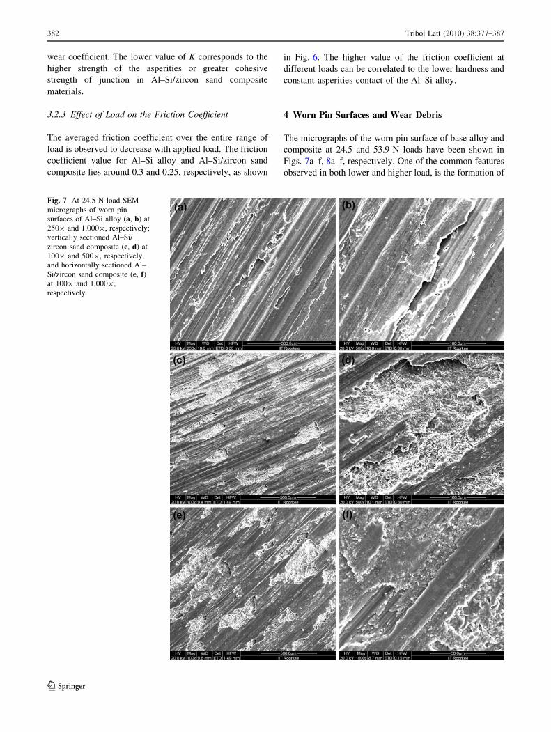
4 Worn Pin Surfaces and Wear Debris
The micrographs of the worn pin surface of base alloy and
composite at 24.5 and 53.9 N loads have been shown in
Figs. 7a–f, 8a–f, respectively. One of the common features
observed in both lower and higher load, is the formation of
Fig. 7 At 24.5 N load SEM
micrographs of worn pin
surfaces of Al–Si alloy (a, b) at
2509 and 1,0009, respectively;
vertically sectioned Al–Si/
zircon sand composite (c, d) at
1009 and 5009, respectively,
and horizontally sectioned Al–
Si/zircon sand composite (e, f)at 1009 and 1,0009,
respectively
382 Tribol Lett (2010) 38:377–387
123
grooves and ridges running parallel to the sliding direction
in both base alloy and composite. These wear scars are the
primarily characteristic of abrasive wear. On further ana-
lyzing, it has been found that grooves are fine on the worn
pin surface of Al–Si alloy subjected to 24.5 N load
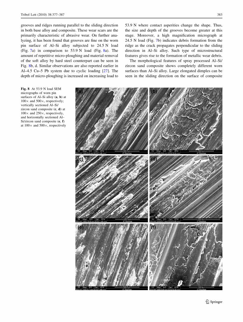
(Fig. 7a) in comparison to 53.9 N load (Fig. 8a). The
amount of repetitive micro-ploughing and material removal
of the soft alloy by hard steel counterpart can be seen in
Fig. 8b, d. Similar observations are also reported earlier in
Al–4.5 Cu–5 Pb system due to cyclic loading [27]. The
depth of micro-ploughing is increased on increasing load to
53.9 N where contact asperities change the shape. Thus,
the size and depth of the grooves become greater at this
stage. Moreover, a high magnification micrograph at
24.5 N load (Fig. 7b) indicates debris formation from the
ridge as the crack propagates perpendicular to the sliding
direction in Al–Si alloy. Such type of microstructural
features gives rise to the formation of metallic wear debris.
The morphological features of spray processed Al–Si/
zircon sand composite shows completely different worn
surfaces than Al–Si alloy. Large elongated dimples can be
seen in the sliding direction on the surface of composite
Fig. 8 At 53.9 N load SEM
micrographs of worn pin
surfaces of Al–Si alloy (a, b) at
1009 and 5009, respectively;
vertically sectioned Al–Si/
zircon sand composite (c, d) at
1009 and 2509, respectively,
and horizontally sectioned Al–
Si/zircon sand composite (e, f)at 1009 and 5009, respectively
Tribol Lett (2010) 38:377–387 383
123
material shown in Figs. 7c, e, 8c, e, respectively. Similar
morphology is indicated by other researchers in ceramic
reinforced AMCs [28, 29]. Moreover, width of grooves and
elongation of dimples predominates as the load is increased
from 24.5 to 53.9 N in Al–Si/zircon sand composite. The
enlarged view of the dimple (Fig. 7d) indicates the for-
mation of non-uniform tribo-layer on the worn surface.
Also, the formed tribo-layer is heterogeneous in nature and
morphology of craters predicts the formation of oxide
debris. At 24.5 N load the smaller size of dimples and fine
grooves can be seen in vertically sectioned composite
(Fig. 7c) in comparison to horizontally sectioned Al–Si/
zircon sand composite (Fig. 7e). At higher load Fig. 8d
shows the four different morphological features; metal flow
lines, micro-ploughing, propagation of cracks at the
periphery of the crater, and detachment of debris. These
cracks exist due to the surface shearing forces and grow
along the periphery of the crater. Moreover, the mechani-
cally welded layer is also being observed on the worn
surfaces due to the transfer of counterpart steel disc
material as well as the compaction of the oxide debris on
the sliding pin which is clearly indicated in Figs. 7f, 8f.
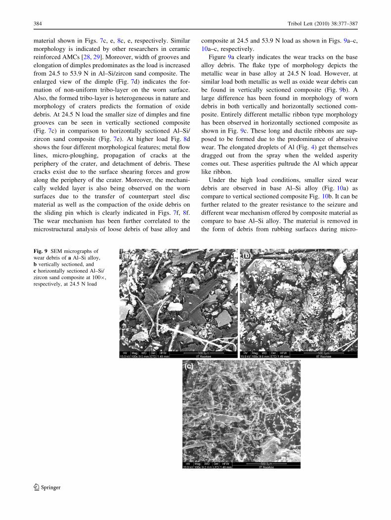
The wear mechanism has been further correlated to the
microstructural analysis of loose debris of base alloy and
composite at 24.5 and 53.9 N load as shown in Figs. 9a–c,
10a–c, respectively.
Figure 9a clearly indicates the wear tracks on the base
alloy debris. The flake type of morphology depicts the
metallic wear in base alloy at 24.5 N load. However, at
similar load both metallic as well as oxide wear debris can
be found in vertically sectioned composite (Fig. 9b). A
large difference has been found in morphology of worn
debris in both vertically and horizontally sectioned com-
posite. Entirely different metallic ribbon type morphology
has been observed in horizontally sectioned composite as
shown in Fig. 9c. These long and ductile ribbons are sup-
posed to be formed due to the predominance of abrasive
wear. The elongated droplets of Al (Fig. 4) get themselves
dragged out from the spray when the welded asperity
comes out. These asperities pultrude the Al which appear
like ribbon.
Under the high load conditions, smaller sized wear
debris are observed in base Al–Si alloy (Fig. 10a) as
compare to vertical sectioned composite Fig. 10b. It can be
further related to the greater resistance to the seizure and
different wear mechanism offered by composite material as
compare to base Al–Si alloy. The material is removed in
the form of debris from rubbing surfaces during micro-
Fig. 9 SEM micrographs of
wear debris of a Al–Si alloy,
b vertically sectioned, and
c horizontally sectioned Al–Si/
zircon sand composite at 1009,
respectively, at 24.5 N load
384 Tribol Lett (2010) 38:377–387
123
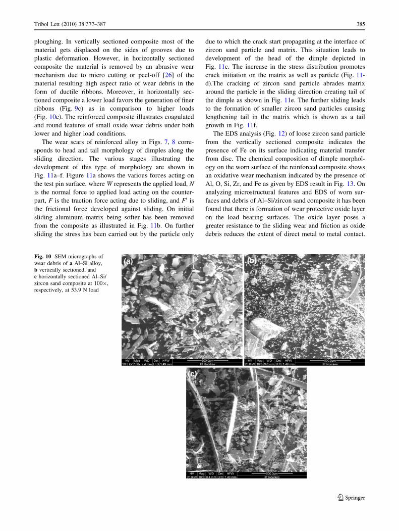
ploughing. In vertically sectioned composite most of the
material gets displaced on the sides of grooves due to
plastic deformation. However, in horizontally sectioned
composite the material is removed by an abrasive wear
mechanism due to micro cutting or peel-off [26] of the
material resulting high aspect ratio of wear debris in the
form of ductile ribbons. Moreover, in horizontally sec-
tioned composite a lower load favors the generation of finer
ribbons (Fig. 9c) as in comparison to higher loads
(Fig. 10c). The reinforced composite illustrates coagulated
and round features of small oxide wear debris under both
lower and higher load conditions.
The wear scars of reinforced alloy in Figs. 7, 8 corre-
sponds to head and tail morphology of dimples along the
sliding direction. The various stages illustrating the
development of this type of morphology are shown in
Fig. 11a–f. Figure 11a shows the various forces acting on
the test pin surface, where W represents the applied load, N
is the normal force to applied load acting on the counter-
part, F is the traction force acting due to sliding, and F0 is
the frictional force developed against sliding. On initial
sliding aluminum matrix being softer has been removed
from the composite as illustrated in Fig. 11b. On further
sliding the stress has been carried out by the particle only
due to which the crack start propagating at the interface of
zircon sand particle and matrix. This situation leads to
development of the head of the dimple depicted in
Fig. 11c. The increase in the stress distribution promotes
crack initiation on the matrix as well as particle (Fig. 11-
d).The cracking of zircon sand particle abrades matrix
around the particle in the sliding direction creating tail of
the dimple as shown in Fig. 11e. The further sliding leads
to the formation of smaller zircon sand particles causing
lengthening tail in the matrix which is shown as a tail
growth in Fig. 11f.
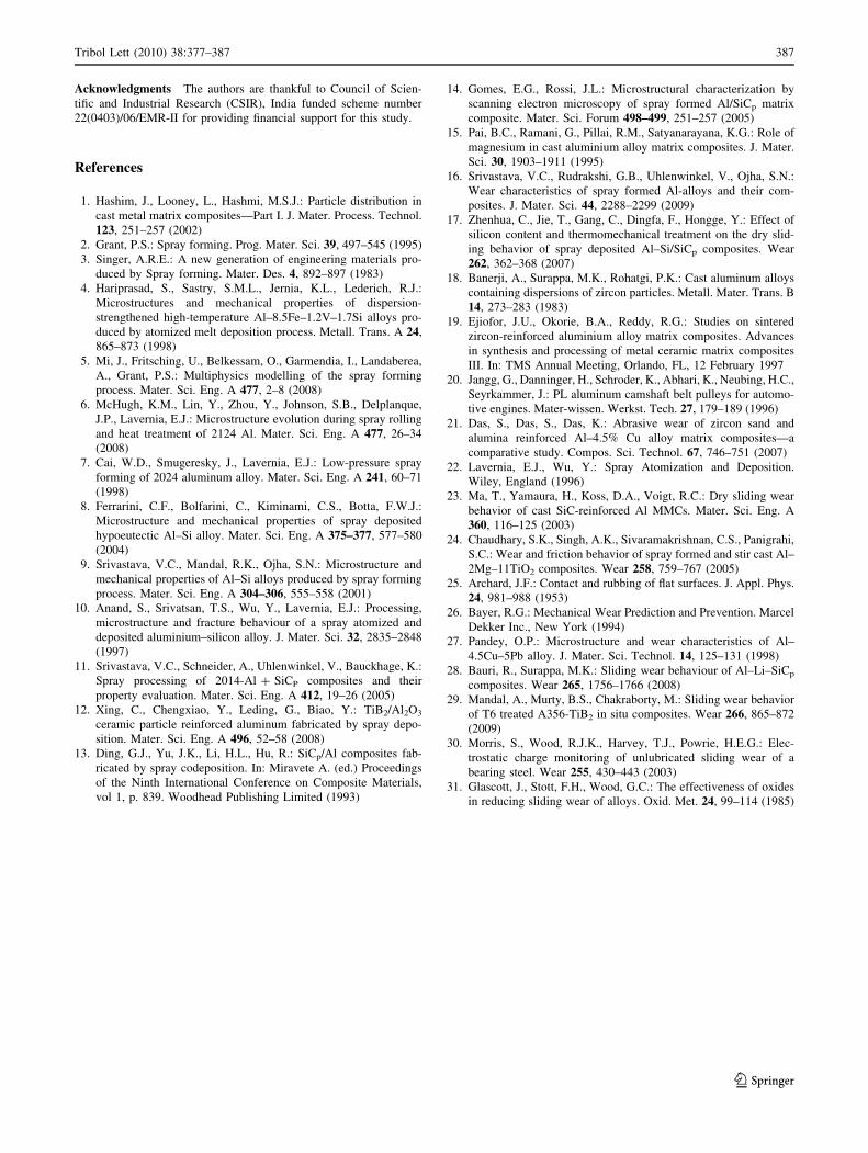
The EDS analysis (Fig. 12) of loose zircon sand particle
from the vertically sectioned composite indicates the
presence of Fe on its surface indicating material transfer
from disc. The chemical composition of dimple morphol-
ogy on the worn surface of the reinforced composite shows
an oxidative wear mechanism indicated by the presence of
Al, O, Si, Zr, and Fe as given by EDS result in Fig. 13. On
analyzing microstructural features and EDS of worn sur-
faces and debris of Al–Si/zircon sand composite it has been
found that there is formation of wear protective oxide layer
on the load bearing surfaces. The oxide layer poses a
greater resistance to the sliding wear and friction as oxide
debris reduces the extent of direct metal to metal contact.
Fig. 10 SEM micrographs of
wear debris of a Al–Si alloy,
b vertically sectioned, and
c horizontally sectioned Al–Si/
zircon sand composite at 1009,
respectively, at 53.9 N load
Tribol Lett (2010) 38:377–387 385
123
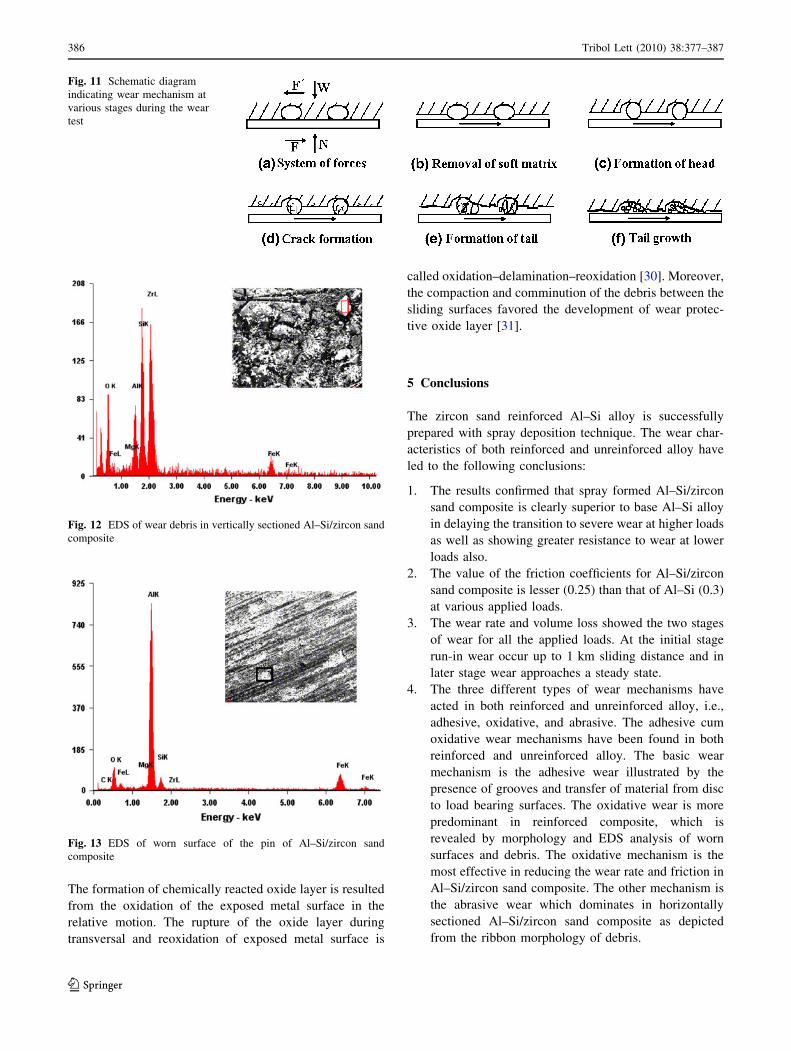
The formation of chemically reacted oxide layer is resulted
from the oxidation of the exposed metal surface in the
relative motion. The rupture of the oxide layer during
transversal and reoxidation of exposed metal surface is
called oxidation–delamination–reoxidation [30]. Moreover,
the compaction and comminution of the debris between the
sliding surfaces favored the development of wear protec-
tive oxide layer [31].
5 Conclusions
The zircon sand reinforced Al–Si alloy is successfully
prepared with spray deposition technique. The wear char-
acteristics of both reinforced and unreinforced alloy have
led to the following conclusions:
1. The results confirmed that spray formed Al–Si/zircon
sand composite is clearly superior to base Al–Si alloy
in delaying the transition to severe wear at higher loads
as well as showing greater resistance to wear at lower
loads also.
2. The value of the friction coefficients for Al–Si/zircon
sand composite is lesser (0.25) than that of Al–Si (0.3)
at various applied loads.
3. The wear rate and volume loss showed the two stages
of wear for all the applied loads. At the initial stage
run-in wear occur up to 1 km sliding distance and in
later stage wear approaches a steady state.
4. The three different types of wear mechanisms have
acted in both reinforced and unreinforced alloy, i.e.,
adhesive, oxidative, and abrasive. The adhesive cum
oxidative wear mechanisms have been found in both
reinforced and unreinforced alloy. The basic wear
mechanism is the adhesive wear illustrated by the
presence of grooves and transfer of material from disc
to load bearing surfaces. The oxidative wear is more
predominant in reinforced composite, which is
revealed by morphology and EDS analysis of worn
surfaces and debris. The oxidative mechanism is the
most effective in reducing the wear rate and friction in
Al–Si/zircon sand composite. The other mechanism is
the abrasive wear which dominates in horizontally
sectioned Al–Si/zircon sand composite as depicted
from the ribbon morphology of debris.
Fig. 11 Schematic diagram
indicating wear mechanism at
various stages during the wear
test
Fig. 12 EDS of wear debris in vertically sectioned Al–Si/zircon sand
composite
Fig. 13 EDS of worn surface of the pin of Al–Si/zircon sand
composite
386 Tribol Lett (2010) 38:377–387
123
Acknowledgments The authors are thankful to Council of Scien-
tific and Industrial Research (CSIR), India funded scheme number
22(0403)/06/EMR-II for providing financial support for this study.
References
1. Hashim, J., Looney, L., Hashmi, M.S.J.: Particle distribution in
cast metal matrix composites—Part I. J. Mater. Process. Technol.
123, 251–257 (2002)
2. Grant, P.S.: Spray forming. Prog. Mater. Sci. 39, 497–545 (1995)
3. Singer, A.R.E.: A new generation of engineering materials pro-
duced by Spray forming. Mater. Des. 4, 892–897 (1983)
4. Hariprasad, S., Sastry, S.M.L., Jernia, K.L., Lederich, R.J.:
Microstructures and mechanical properties of dispersion-
strengthened high-temperature Al–8.5Fe–1.2V–1.7Si alloys pro-
duced by atomized melt deposition process. Metall. Trans. A 24,
865–873 (1998)
5. Mi, J., Fritsching, U., Belkessam, O., Garmendia, I., Landaberea,
A., Grant, P.S.: Multiphysics modelling of the spray forming
process. Mater. Sci. Eng. A 477, 2–8 (2008)
6. McHugh, K.M., Lin, Y., Zhou, Y., Johnson, S.B., Delplanque,
J.P., Lavernia, E.J.: Microstructure evolution during spray rolling
and heat treatment of 2124 Al. Mater. Sci. Eng. A 477, 26–34
(2008)
7. Cai, W.D., Smugeresky, J., Lavernia, E.J.: Low-pressure spray
forming of 2024 aluminum alloy. Mater. Sci. Eng. A 241, 60–71
(1998)
8. Ferrarini, C.F., Bolfarini, C., Kiminami, C.S., Botta, F.W.J.:
Microstructure and mechanical properties of spray deposited
hypoeutectic Al–Si alloy. Mater. Sci. Eng. A 375–377, 577–580
(2004)
9. Srivastava, V.C., Mandal, R.K., Ojha, S.N.: Microstructure and
mechanical properties of Al–Si alloys produced by spray forming
process. Mater. Sci. Eng. A 304–306, 555–558 (2001)
10. Anand, S., Srivatsan, T.S., Wu, Y., Lavernia, E.J.: Processing,
microstructure and fracture behaviour of a spray atomized and
deposited aluminium–silicon alloy. J. Mater. Sci. 32, 2835–2848
(1997)
11. Srivastava, V.C., Schneider, A., Uhlenwinkel, V., Bauckhage, K.:
Spray processing of 2014-Al ? SiCP composites and their
property evaluation. Mater. Sci. Eng. A 412, 19–26 (2005)
12. Xing, C., Chengxiao, Y., Leding, G., Biao, Y.: TiB2/Al2O3
ceramic particle reinforced aluminum fabricated by spray depo-
sition. Mater. Sci. Eng. A 496, 52–58 (2008)
13. Ding, G.J., Yu, J.K., Li, H.L., Hu, R.: SiCp/Al composites fab-
ricated by spray codeposition. In: Miravete A. (ed.) Proceedings
of the Ninth International Conference on Composite Materials,
vol 1, p. 839. Woodhead Publishing Limited (1993)
14. Gomes, E.G., Rossi, J.L.: Microstructural characterization by
scanning electron microscopy of spray formed Al/SiCp matrix
composite. Mater. Sci. Forum 498–499, 251–257 (2005)
15. Pai, B.C., Ramani, G., Pillai, R.M., Satyanarayana, K.G.: Role of
magnesium in cast aluminium alloy matrix composites. J. Mater.
Sci. 30, 1903–1911 (1995)
16. Srivastava, V.C., Rudrakshi, G.B., Uhlenwinkel, V., Ojha, S.N.:
Wear characteristics of spray formed Al-alloys and their com-
posites. J. Mater. Sci. 44, 2288–2299 (2009)
17. Zhenhua, C., Jie, T., Gang, C., Dingfa, F., Hongge, Y.: Effect of
silicon content and thermomechanical treatment on the dry slid-
ing behavior of spray deposited Al–Si/SiCp composites. Wear
262, 362–368 (2007)
18. Banerji, A., Surappa, M.K., Rohatgi, P.K.: Cast aluminum alloys
containing dispersions of zircon particles. Metall. Mater. Trans. B
14, 273–283 (1983)
19. Ejiofor, J.U., Okorie, B.A., Reddy, R.G.: Studies on sintered
zircon-reinforced aluminium alloy matrix composites. Advances
in synthesis and processing of metal ceramic matrix composites
III. In: TMS Annual Meeting, Orlando, FL, 12 February 1997
20. Jangg, G., Danninger, H., Schroder, K., Abhari, K., Neubing, H.C.,
Seyrkammer, J.: PL aluminum camshaft belt pulleys for automo-
tive engines. Mater-wissen. Werkst. Tech. 27, 179–189 (1996)
21. Das, S., Das, S., Das, K.: Abrasive wear of zircon sand and
alumina reinforced Al–4.5% Cu alloy matrix composites—a
comparative study. Compos. Sci. Technol. 67, 746–751 (2007)
22. Lavernia, E.J., Wu, Y.: Spray Atomization and Deposition.
Wiley, England (1996)
23. Ma, T., Yamaura, H., Koss, D.A., Voigt, R.C.: Dry sliding wear
behavior of cast SiC-reinforced Al MMCs. Mater. Sci. Eng. A
360, 116–125 (2003)
24. Chaudhary, S.K., Singh, A.K., Sivaramakrishnan, C.S., Panigrahi,
S.C.: Wear and friction behavior of spray formed and stir cast Al–
2Mg–11TiO2 composites. Wear 258, 759–767 (2005)
25. Archard, J.F.: Contact and rubbing of flat surfaces. J. Appl. Phys.
24, 981–988 (1953)
26. Bayer, R.G.: Mechanical Wear Prediction and Prevention. Marcel
Dekker Inc., New York (1994)
27. Pandey, O.P.: Microstructure and wear characteristics of Al–
4.5Cu–5Pb alloy. J. Mater. Sci. Technol. 14, 125–131 (1998)
28. Bauri, R., Surappa, M.K.: Sliding wear behaviour of Al–Li–SiCp
composites. Wear 265, 1756–1766 (2008)
29. Mandal, A., Murty, B.S., Chakraborty, M.: Sliding wear behavior
of T6 treated A356-TiB2 in situ composites. Wear 266, 865–872
(2009)
30. Morris, S., Wood, R.J.K., Harvey, T.J., Powrie, H.E.G.: Elec-
trostatic charge monitoring of unlubricated sliding wear of a
bearing steel. Wear 255, 430–443 (2003)
31. Glascott, J., Stott, F.H., Wood, G.C.: The effectiveness of oxides
in reducing sliding wear of alloys. Oxid. Met. 24, 99–114 (1985)
Tribol Lett (2010) 38:377–387 387
123


![Zircon geochronology and ca. 400 Ma exhumation of ...hacker.faculty.geol.ucsb.edu/...Zircon...Norwegian.pdf · single zircon 238U/206Pb ages from Krogh et al. [15] define two stages](https://img.pdfslide.us/doc/110x75/5f78b0a55661600ea6216daf/zircon-geochronology-and-ca-400-ma-exhumation-of-single-zircon-238u206pb-ages.jpg)