Embed Size (px)
Citation preview
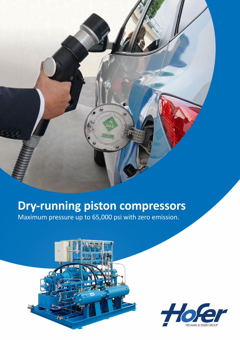
Dry-running piston compressorsMaximum pressure up to 65,000 psi with zero emission.
Hydraulically driven, dry-running HOFER piston compressorsare designed for easy maintenance and allow a lubricant-free compression of non-corrosive gases, which are free from solid particles, such as hydrogen, helium, argon, nitrogen, carbon dioxide and ethylene.
The maximum discharge pressure of the standard design is approx. 14,500 psi (1,000 bar). For higher working pressures up to 65,000 psi (4,500 bar), special designs are available.
This compressor type is built in an easy to maintain construction.A piston packing can be replaced in approx. 10 to 30 minutes, depending on the compressor size.
Working principle
The special construction and design of the piston packing al-lows to operate completely without lubrication of these sealing elements at higher discharge pressures, although under normal circumstances such a lubrication is absolutely required.
The gas piston gets the required sealing and sliding properties by the design of the packing structure with the materials specially developed for this purpose. The gas space and the gas to be compressed are kept free from undesirable lubricants.
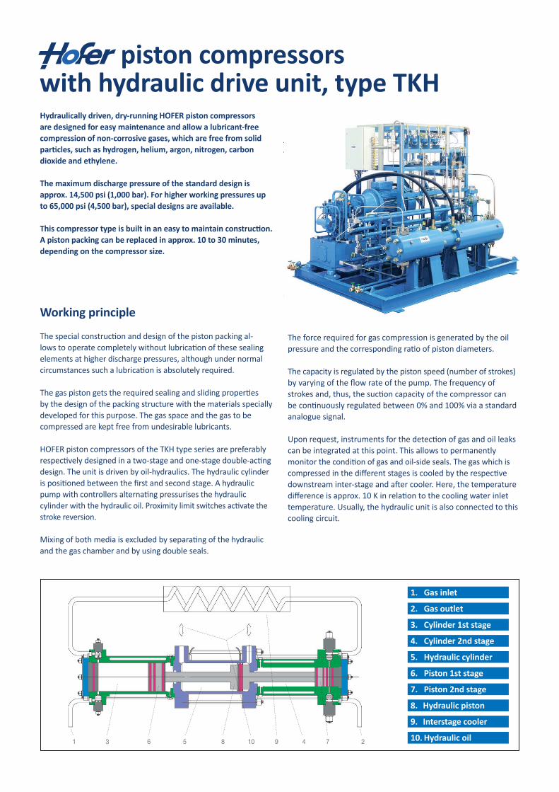
HOFER piston compressors of the TKH type series are preferably respectively designed in a two-stage and one-stage double-acting design. The unit is driven by oil-hydraulics. The hydraulic cylinder is positioned between the first and second stage. A hydraulic pump with controllers alternating pressurises the hydraulic cylinder with the hydraulic oil. Proximity limit switches activate the stroke reversion.
Mixing of both media is excluded by separating of the hydraulic and the gas chamber and by using double seals.
The force required for gas compression is generated by the oil pressure and the corresponding ratio of piston diameters.
The capacity is regulated by the piston speed (number of strokes) by varying of the flow rate of the pump. The frequency of strokes and, thus, the suction capacity of the compressor can be continuously regulated between 0% and 100% via a standard analogue signal.
Upon request, instruments for the detection of gas and oil leaks can be integrated at this point. This allows to permanently monitor the condition of gas and oil-side seals. The gas which is compressed in the different stages is cooled by the respective downstream inter-stage and after cooler. Here, the temperature difference is approx. 10 K in relation to the cooling water inlet temperature. Usually, the hydraulic unit is also connected to this cooling circuit.
piston compressors with hydraulic drive unit, type TKH
The force required for gas compression is generated by
the oil pressure and the corresponding ratio of piston
diameters.
The capacity is regulated by the piston speed (number of
strokes) through varying of the flow rate of the pump. The
frequency of strokes and, thus, the suction capacity of the
compressor can be continuously regulated between 0%
and 100% via a standard analogue signal.
Upon request, instruments for the detection of gas and oil
leaks can be integrated at this point. This allows to perma-
nently monitor the condition of gas- and oil-side seals.
The gas which is compressed in the different stages is
cooled by the respective downstream inter-stage and after
cooler. Here, the temperature difference is approx. 10 K in
relation to the cooling water inlet temperature. Usually, the
hydraulic unit is also connected to this cooling circuit.
1 23 456 78 910
1.
2.
3.
4.
5.
6.
7.
8.
9.
10.
Gas inlet
Gas outlet
Cylinder 1st stage
Cylinder 2nd stage
Hydraulic cylinder
Piston 1st stage
Kolben 2nd stage
Hydraulic piston
Interstage cooler
Hydraulic oil
HOFER piston compressors with hydraulic drive unit
Dry-running HOFER piston compressors
with hydraulic drive unit, type TKH
Hydraulically driven, dry-running HOFER piston compres-
sors are designed for easy maintenance and allow a lubri-
cant-free compression of non-corrosive gases, which are
free from solid particles, such as hydrogen, helium, argon,
nitrogen, carbon dioxide and ethylene.
The maximum discharge pressure of the standard design
is approx. 14.500 psi (1.000 bar). For higher working
pressures up to 65.250 psi (4.500 bar), special designs
are available.
This compressor type is built in an easy to maintain con-
struction. A piston packing can be replaced in approx. 10
to 30 minutes, depending on the compressor size.
Principle of working
The special construction and design of the piston packing
allows to operate completely without the lubrication of
these sealing elements at higher discharge pressures,
although under normal circumstances such a lubrication
is absolutely required.
The gas piston gets the required sealing and sliding pro-
perties by the design of the packing structure with the
materials specially developed for this purpose. The gas
space and the gas to be compressed are kept free from
undesirable lubricants.
HOFER piston compressors of the TKH type series are
preferably designed in a two-stage respectively one-stage
double-acting design. The unit is driven by oil-hydraulics.
The hydraulic cylinder is positioned between the first and
second stage. A hydraulic pump with controllers alternating
pressurises the hydraulic cylinder with the hydraulic oil.
Proximity limit switches activate the stroke reversion.
Mixing of both media is excluded due to the separation of the
hydraulic and the gas chamber and by use of double seals.
1. Gas inlet
2. Gas outlet
3. Cylinder 1st stage
4. Cylinder 2nd stage
5. Hydraulic cylinder
6. Piston 1st stage
7. Piston 2nd stage
8. Hydraulic piston
9. Interstage cooler
10. Hydraulic oil
Installation of HOFER piston compressors in
hazardous areas
For the use of the compressors in hazardous areas, two
alternatives can be supplied:
Installation of the cylinder set in the hazardous area
(zone 2 or 1) and installation of the hydraulic system in
the non-hazardous area. The hydraulic oil unit is
connected through a gastight wall.
Installation of the cylinder set and the hydraulic unit in
the non-hazardous area (zone 2).
Capacity, compression ratios, pressure stages
The suction capacity of the compressor is determined by
the suction pressure, the discharge pressure and the
frequency of strokes. For different models please refer to
the attached tables (other performance data upon request).
The stated driving powers apply to the maximum operating
data.
Model designation
The main dimensions are encoded in the type designation
for the Hofer TKH piston compressors:
Two-stage dry-running piston compressor with
hydraulic drive unit TKH 52/36 -200 -50
Piston diameter first stage: 52 mm
Piston diameter second stage: 36 mm
Stroke: 200 mm
Max. allowable discharge pressure: 7.250 psi (500 bar)
One-stage double-acting compressor (e.g. booster)
TKH 28/28 -80 -100
Piston diameter 1A. stage: 28 mm
Piston diameter 1B. stage: 28 mm
Stroke: 80 mm
Max. allowable discharge pressure: 14.500 psi (1.000 bar)
Equipment
The HOFER compressors of the TKH model series can be
supplied as a compressor without accessories or turn-key
as a complete operational unit with all necessary devices,
fittings and instruments.
Acceptances and certifications
The standards and directives applicable in the European
Community
Directive for Machinery 98/37/EG
Pressure Equipment Directive 97/23/EG
ATEX Directive 94/9/EG
Low Voltage Directive 93/68/EWG
as well as in above mentioned applicable standards are
the basis of our construction and design.
Compliance with the applicable directives is confirmed by
the conformity declaration respectively the manufacturer's
declaration and the CE marking of the compressor.
US standards: For the American market, the applicable
US regulations and standards are complied with.
Prior to delivery, each HOFER piston compressor is
subjected to a test run under operating conditions for
several hours. Upon request, the customer participates
the test run.
1.
2.
Type TKH for 65.250 psi (4.500 bar)
Installation of HOFER piston compressors in hazardous areasFor the use of the compressors in hazardous areas, twoalternatives can be supplied:
1. Installation of the cylinder set in the hazardous area (zone 2 or 1) and installation of the hydraulic system in the non-hazardous area. The hydraulic oil unit is connected through a gas-tight wall.
2. Installation of the cylinder set and the hydraulic unit in the non-hazardous area (zone 2).
Capacity, compression ratios, pressure stages
The suction capacity of the compressor is determined by the suction pressure, the discharge pressure and the frequency of strokes. For different models please refer to the attached tables (other performance data upon request). The stated driving powers apply to the maximum operating data.
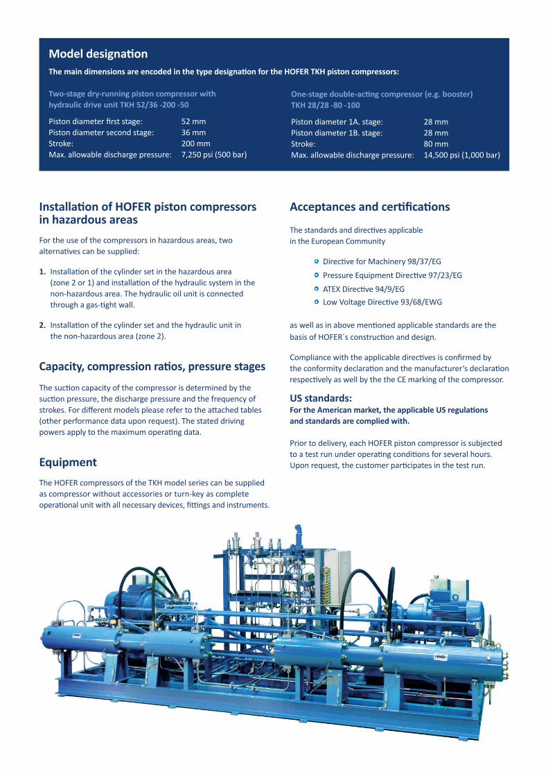
EquipmentThe HOFER compressors of the TKH model series can be supplied as compressor without accessories or turn-key as complete operational unit with all necessary devices, fittings and instruments.
Acceptances and certifications
The standards and directives applicable in the European Community Directive for Machinery 98/37/EG Pressure Equipment Directive 97/23/EG ATEX Directive 94/9/EG Low Voltage Directive 93/68/EWG
as well as in above mentioned applicable standards are the basis of HOFER´s construction and design.
Compliance with the applicable directives is confirmed by the conformity declaration and the manufacturer‘s declaration respectively as well by the the CE marking of the compressor.
US standards: For the American market, the applicable US regulations and standards are complied with.
Prior to delivery, each HOFER piston compressor is subjected to a test run under operating conditions for several hours. Upon request, the customer participates in the test run.
Model designationThe main dimensions are encoded in the type designation for the HOFER TKH piston compressors:
Two-stage dry-running piston compressor withhydraulic drive unit TKH 52/36 -200 -50
Piston diameter first stage: 52 mmPiston diameter second stage: 36 mmStroke: 200 mmMax. allowable discharge pressure: 7,250 psi (500 bar)
One-stage double-acting compressor (e.g. booster)TKH 28/28 -80 -100
Piston diameter 1A. stage: 28 mmPiston diameter 1B. stage: 28 mmStroke: 80 mmMax. allowable discharge pressure: 14,500 psi (1,000 bar)
Andreas Hofer Hochdrucktechnik GmbH
Ruhrorter Straße 45
D-45478 Mülheim an der Ruhr
Germany
Fon +49-(0)208-4 69 96- 0
Fax +49-(0)208-4 69 96-11
Web www.andreas-hofer.de
Email [email protected]
"Zur Sicherheit – Hofer-Qualität"
HOFER SERVICE DEU 2/2 © by Andreas Hofer GmbH 04.08
Industries
HOFER compressors are used in nearly every industry in which high-purity, rare or hazardous gases are utilized.
Some specific applications are:
PTA plants (prod. of terephthalic acid)
Gas cylinder filling, gas blending and mixing systems
Chemical, pharmaceutical and petrochemical plants
Gas transfer, filling and off-loading of tube trailers
Electronics, semiconductor and fiber optics manufacturing
Hydrogen filling stations
Research and development
Pressure boosting and high-pressure gas storage systems
Space centers
www.hofer-highpressure.com
Andreas Hofer Hochdrucktechnik GmbHRuhrorter Straße 45D-45478 Mülheim an der Ruhr
Phone +49 (0) 208 4 69 96 0Fax +49 (0) 208 4 69 96 11e-mail [email protected]


![Biografie Florian Hofer [Deutsch]](https://img.pdfslide.us/doc/110x75/568c3b971a28ab0235aab3bb/biografie-florian-hofer-deutsch.jpg)