Embed Size (px)
Citation preview

Dry Coolers anD ConDensers for InDustrIal applICatIons

2
leadership with passion

3
LU-VE Group 04
Application fields 06
Product configuration 08
Application examples 22
Contents

4
the LU-VE name has become the international reference point for all that is best in the design, production and sales of heat exchangers and other components for equipment used in commercial and industrial refrigeration, air conditioning, industrial applications and close control air conditioning.the LU-VE Group of today, with its headquarters inuboldo (Varese), Italy, has been made possible thanks to a continuous process of cultural and technological innovation starting in 1928 and still continuing strongly now.the strength of the Group lies in its 8 production facilities and 14 sales companies.
the important numbers are:• 1,350 highly skilled employees• 330,000 m2 of total surface area (125,000 m2 covered)• 1,300 m2 of research and development laboratories• 70% of products exported to 90 countries• €220 million aggregate turnover.
The Group
Italy Poland RussIa
Changshu
ChIna sweden CzeCh ReP. Italy Italy
PolsKa RussIa sPaIn uK - eIResInGaPoReMIddle east
austRIa FRanCe GeRManyasIa PaCIFIC austRalIa CaRIBe IndIa

5
LU-VE S.p.A - Uboldo (Va), Italy
LU-VE s.p.a. is the holding company of lu-Ve Group.In 1985 LU-VE s.p.a. acquired Contardo s.p.a., established in 1928. production began in 1986.LU-VE quickly made its mark thanks to high standards of quality, new solutions designed in its own laboratories and to the care taken with the appearance of its products. (Beautiful outside - revolutionary inside).It has been the first company in the world to apply avant-garde solutions to commercial and industrial refrigeration:
• grooved tube technology • specialized heat exchange surfaces • certified performance levels • innovative materials and colours • advanced design
the success of LU-VE in the international market stems from its research and development policy, its great respect for the environment and its rigorous ethical and commercial principles.In 2000, LU-VE was the first company in Europe to attain the prestigious Eurovent “Certify-All” certification for the entire range of its products: unit coolers, condensers and dry coolers.LU-VE and the Group have introduced new ways of conceiving and constructing products for refrigeration, air conditioning and industrial applications, creating new technologies which have then gone on to become the benchmark for the entire industry.
LU-VE SpA
LU-VE Sweden AB/AIALU-VE Sweden - As rum, Sweden
AIA, established in 1960, has over half a century of experience in the heat exchanger business and is today one of the leading companies in the industry in the scandinavian market. the company is noted in particular for the excellent quality of its products, which are designed on the principles of high efficiency and energy savings. the defining characteristics of the company are competence, flexibility, reliability and customer care.
AIA became part of the LU-VE Group in 2012. It has a modern production facility (total area 37000 sqm, 12000 sqm covered) and a research and development laboratory in asarum, in the south of sweden. aIa produces heat exchangers for industrial and commercial refrigeration, air conditioning and industrial applications, using advanced control systems, high-efficiency motors and water spray features.
a

6
Dry Coolers anD ConDensers for InDustrIal applICatIons

7
• Electricitygeneration(gasturbines,gasordieselreciprocatingengines,ORCsystems,cogeneration,geothermalplants)
• Oilandgasindustry
• Coolingofwaterusedinindustrialprocesses
• Automotiveindustry
• Wastetreatmentplants
• Chemicalandpharmaceuticalindustries
• Die-coolingintheproductionofplastics
the new eaV/eal poWer range of horizontal units and the new EHLD/EHVD/XXLD POWER series with “V” formation coils have been specifically designed to fulfil the typical requirements of industrial installations, with particular reference to these applications:
the lu-Ve Group has a great deal of experience with these applications and can work alongside the designer in selecting the best configuration of the product to match the needs of the specific plant solution.

8
Product configuration
heat exchanger
the heat exchanger geometry used in these machines - designed in line with the most modern dictates of Computational fluid Dynamics enables very high capacity of heat transfer and power density to be achieved. this means that we can offer a product which can reduce dimensions, increase energy efficiency and minimize the amount of internal fluid (a very important feature if hazardous fluids are used). the condensing heat exchangers have special tubes with internal helicoid grooves which increase heat transfer efficiency. the great versatility of its construction enables optimized solutions to be identified for different applications.
LU-VE has always led the field in the creation of very high efficiency heat exchangers. this has been made possible by the use of sophisticated methods of numerical simulation (CfD), capable of predicting with precision the fields of pressure, temperature and velocity which are generated within the heat exchanger, thus optimizing the heat transfer coefficient and minimizing pressure drop.
In addition to numerical analysis, research activities are conducted in the experimental laboratories of lu-Ve, which are equipped with:
• 3 climatic test chambers to measure the capacity of the exchangers • 2 tunnels to measure the characteristic curves of the fans and the
relative electrical power draw• 1 tunnel to measure heat exchange coefficients and air side pressure
drop of the exchanger• Plant to measure heat exchange coefficients and internal tubes side
pressure drop of the heat exchanger• 1 semi-reverberation chamber to measure sound level.

9
Product configuration
The product has copper tubes and aluminium fins. The tubes are mechanically expanded to guarantee the best contact between tube and fin.the headers of the dry cooler version are made of copper with an aluminium floating flange attachment.
the headers of the condenser version are made of copper or carbon steel depending on the application.the casing of the heat exchanger is made of galvanized steel (to unI 5961 standard), polyester-powder coated, colour ral9003. Corrosion resistance in compliance with EN ISO 12944, classification “C4”.
Construction materials
Different materials for the heat exchanger are available on request, as described here:
the copper tubes used for the heat exchanger conform to the general indications in standards en 1412 – astM B 111 – astM B 280.The aluminium used for the heat exchanger fins conforms to the general indications of ansI H 35.1-88 and astM B 247.screws and fasteners are made of stainless steel aIsI 304 class a2-70.
standaRd ConFIGuRatIons sPeCIal ConFIGuRatIons
Tubes Cu DHP CuNi 90-10, CuSn,SS AISI 304L, SS AISI 316L
Fins Al – alloy 8006Alupaint(*), Cu DHP, CuSn, heat
exchanger painted after construction (Blygold, Heresite,…)
Headers Cu DHP Fe (ASTM A106 gr B), SS AISI 304L, SS AISI 316
Casing Galvanized steel, powder-coated, RAL 9003 (C4 corrosion resistance) SS AISI 304L, SS AISI 316L
NOTE: certain configurations of materials may restrict maximum dimensions; contact LU-VE for more details.
(*)Alupaint: pre-polyester-painted aluminium strip capable of withstanding 1000 hours in salt spray test (ASTM B117).

10
Fan diameters 800 - 910 - 1,000 mm fan-motors with external aluminium or composite material rotors. In this configuration the fan-motor is a single piece and has several advantages: compact design, excellent aerolic and electrical efficiency, lightness, and it is easy to replace. Insulation class f, protection grade Ip 54. on request, fan-motors can be painted and the windings double-impregnated for use in especially severe environments.these fans can be regulated by cut-phase controller or inverter. In the latter case, the inverter must have sinusoidal filters between phase and phase and between phase and ground. On request, fans with electronic (EC) motors can be fitted to reduce energy consumption (see dedicated manual).Maximum reliability thanks to the numerous fans, which limit loss of performance in the event of one motor failing.Maximum simplicity of replacement without the need for lifting equipment.
Fan Axial fans are fitted, lubricated for life and balanced both statically and dynamically. Balance grade G6.3 (to Iso 1940 part 1).the protective fan grilles conform to the en 294 standard.

11
Fan diameters 1,250 mm or morefan-motors with traditional internal rotors, directly coupled to the fan, generally constructed in ppG, paG, al. Insulation class f or H, protection grade Ip 55. the motors can be supplied with different grades of mechanical and electrical protection depending on the intended type of use. these motors can be regulated by inverter. In this configuration, the fan group can be best suited to the needs of the plant, permitting high levels of air quantity to be achieved and thus maximizing heat exchange capacity at equal dimensions.

12
the machines can be equipped with various accessories to facilitate installation and maintenance, such as:
accessories
External connecting headers between
the various connections of the heat exchanger
Platforms and frames
1
2

13
Inspection panels and hinged fan shrouds to facilitate maintenance and cleaning of the heat exchanger
If the machine is required to operate with pure water and it is essential to guarantee complete drainage of the heat exchanger, a special version is available with extra drainage header.
3

14
the machines can be supplied with different electrical configurations for the various plant requirements, both at the level of electrical panels and also for speed controllers capable of modulating the capacity of the heat exchanger depending on conditions in order to save energy.
Some examples of electrical panels
Control and regulation systems
a wide range of regulation systems, inverters, cut-phase controllers, transformer controllers can be supplied in order to best regulate the operation of the machine.

15
Control and regulation systems
Benefits of electronic regulation
regulating the capacity of dry coolers is often done by starting and stopping the fans in sequence. Instead, the use of an electronic controller provides great energy savings thanks to the continuous modulation of all the fans.
Electronic regulation (sample)
full load (∆t = 15K) 576 kWConsumption 8.32 kw
sound power level 85 dB(a)
ON/OFFregulationofthefans
Fanspeedcontroller(transformer)
Partialload1/2capacity
-50% Consumption (4.16kw)-3 dB(a) lw -70% Consumption (2.56 kw)
-19 dB(a) lw
example: eaV9X 1241

16
lu-Ve proposes eC brushless fan technology.this guarantees even greater energy savings, thanks to the superior efficiency of the motor.
• Maximum reduction of electrical power draw (-20% on average)
• Maximum noise reduction during the regulation process
• self-protected motor
• Integrated speed control
90
80
70
60
50
40
30
20
10
Motorefficiency[%]
0 50 100 150 200 250 300 350 400 450 500
OutputpowerP2[W]
eC- Motor
3~aC
1~aC
Main advantages
Energy saving

17
•
• Maximum noise reduction during the regulation process
• self-protected motor
• Integrated speed control
eC- Motor
3~aC
1~aC
ModBus
EC-FansWMC2controller
In order to best command the eC fans and fully exploit all potentialities, lu-Ve has developed the innovative WMC2 controller which permits extremely precise regulation, reducing noise and energy consumption at the same time. and thanks to Modbus rtu digital communication, all information concerning the functioning of the unit can be made available. Energy saving
Bus communication to BMs

18
The coil is suspended by the LU-VE patented SAFETUBES SYSTEM®
this exclusive coil suspension system, (patented by lu-Ve) completely prevents any contact between the tubes and the frame of the dry cooler and guarantees complete protection of the coil during transport, installation and operation.
the mechanical structure has been designed according to the most modern criteria and verified together with experts from the politecnico di Milano using finite element Method (feM) to guarantee maximum reliability.
Construction of the productCodice di commessa N° 43/09 – “Ottimizzazione strutturale di uno
POLITECNICO DI MILANO – DIPARTIMENTO DI
Le prime due frequenze proprie che interessano la struttura sonorappresentano un incremento rispetto alle frequenza della struttura con losanghe di rinforzo.
Nelle figure seguenti sono riportate le funzioni di trasferimento delle accelerazioni verticali della struttura rispetto ad un ingresso di pura accelerazione verticale e rispetto ad una pura accelerazione di rollio. La accelerazione verticale è misurata accelerometro di sinistra posto sulla partedel punto dove era stato posizionato un accelerometro durante le misure sul campo (capitolo 4, figura 4.3).
Ottimizzazione strutturale di uno scambiatore di calore al fine del trasporto
IPARTIMENTO DI MECCANICA
proprie che interessano la struttura sono rappresentano un incremento rispetto alle frequenza della struttura con losanghe di
Nelle figure seguenti sono riportate le funzioni di trasferimento delle accelerazioni struttura rispetto ad un ingresso di pura accelerazione verticale e rispetto
ad una pura accelerazione di rollio. La accelerazione verticale è misurata accelerometro di sinistra posto sulla parte superiore della struttura
dove era stato posizionato un accelerometro durante le misure sul campo
scambiatore di calore al fine del trasporto”
31
a 5.07 e 6.93 Hz e rappresentano un incremento rispetto alle frequenza della struttura con losanghe di
Nelle figure seguenti sono riportate le funzioni di trasferimento delle accelerazioni struttura rispetto ad un ingresso di pura accelerazione verticale e rispetto
ad una pura accelerazione di rollio. La accelerazione verticale è misurata dalla superiore della struttura, in corrispondenza
dove era stato posizionato un accelerometro durante le misure sul campo
Codice di commessa N° 43/09 – “Ottimizzazione strutturale di uno
POLITECNICO DI MILANO – DIPARTIMENTO DI
Le prime due frequenze proprie che interessano la struttura sonorappresentano un incremento rispetto alle frequenza della struttura con losanghe di rinforzo.
Nelle figure seguenti sono riportate le funzioni di trasferimento delle accelerazioni verticali della struttura rispetto ad un ingresso di pura accelerazione verticale e rispetto ad una pura accelerazione di rollio. La accelerazione verticale è misurata accelerometro di sinistra posto sulla partedel punto dove era stato posizionato un accelerometro durante le misure sul campo (capitolo 4, figura 4.3).
Ottimizzazione strutturale di uno scambiatore di calore al fine del trasporto
IPARTIMENTO DI MECCANICA
proprie che interessano la struttura sono rappresentano un incremento rispetto alle frequenza della struttura con losanghe di
Nelle figure seguenti sono riportate le funzioni di trasferimento delle accelerazioni struttura rispetto ad un ingresso di pura accelerazione verticale e rispetto
ad una pura accelerazione di rollio. La accelerazione verticale è misurata accelerometro di sinistra posto sulla parte superiore della struttura
dove era stato posizionato un accelerometro durante le misure sul campo
scambiatore di calore al fine del trasporto”
31
a 5.07 e 6.93 Hz e rappresentano un incremento rispetto alle frequenza della struttura con losanghe di
Nelle figure seguenti sono riportate le funzioni di trasferimento delle accelerazioni struttura rispetto ad un ingresso di pura accelerazione verticale e rispetto
ad una pura accelerazione di rollio. La accelerazione verticale è misurata dalla superiore della struttura, in corrispondenza
dove era stato posizionato un accelerometro durante le misure sul campo

19
Construction of the product SILENCER - THE WHISPERER®
this compact silencer, designed and tested in the lu-Ve laboratories, dramatically reduces sound pressure level up to 5 dB(a). This significant result has been confirmed by tests carried out by TÜV of Munich.Condensers and dry coolers with tHe WHIsperer® provide the following benefits:• Energy savings up to 10%• Reduction of sound pressure level at equal capacity• Increase of capacity at equal sound pressure level• Smaller unit footprint at equal capacity and sound pressure level• Elimination of warm air recirculation.

20
For large capacity air cooled condensers and dry coolers.
Hours/Year1 10 100 1000 10000
930
3336
30272421
181512963
0-3
-6-9
-12-15
°C Ambient Temperature OPERATING
20 °C
OPERATING
SPRAY
DRY
after exhaustive research into increasing the spray system capacities, the new "Dry and spray®" range was created. The extraordinary performance levels due to highly efficient water nebulizzation mean that this product is an alternative to traditional cooling towers with additional important advantages.
The “DRY and SPRAY®” products work as traditional dry units until the ambient air temperature is low enough to maintain the cooling capacity and the coolant temperature (or condensing pressure) at the planned conditions (Dry operation). the temperature passage from Dry to spray operation is a planning choice and usually is about 20°C.this innovative technology also enables, depending on the ambient air wet bulb temperature, a coolant temperature equal to or lower than the dry bulb temperature of ambient air with significant energy advantages.a sophisticated control system adjusts the speed of the fans and the nebulised water capacity as required.
DRY and SPRAY®

21
Hours/Year1 10 100 1000 10000
930
3336
30272421
181512963
0-3
-6-9
-12-15
°C Ambient Temperature OPERATING
20 °C
OPERATING
20
SPRAY
DRY
NOHealth hazards (i.e. LEGIONELLA)related to open warmwater reservoirs
LOWER WATER CONSUMPTION
Annual water consumption for a generic industrial installation (on average from 3 to 10 times less than a traditional cooling tower)
100%
90%
80%
70%
60%
50%
40%
30%
20%
10%
0 %
ANNUAL WATER CONSUMPTION
COOLINGTOWER
HYBRIDCOOLER
I N D U S T R I A L P L A N T
DRY and SPRAYLU-VE
LESS Water consumption!Energy! Noise!Pollution! Operating cost!
The use of “DRY and SPRAY®” liquid coolers and condensers instead of traditional “evaporative cooling towers” and “evaporative condensers” is characterized by the following important advantages:
• Water consumption in SPRAY operation mode is limited to short periods per year. for long periods of the year during Dry operation mode no water is used
• There is no tray containing warm stagnant water under the coil, thus excluding any chance of impure water concentration and the general risk of environmental contamination (NO Legionella)
• Plant operating without water droplet drag-out to the environment and the formation of ugly vapour plumes
• Low energy consumption• Low noise operation• Short plant redemption period• High thermal capacity can be obtained by free cooling
Refer to specific catalogue for nebulised water quality.
22
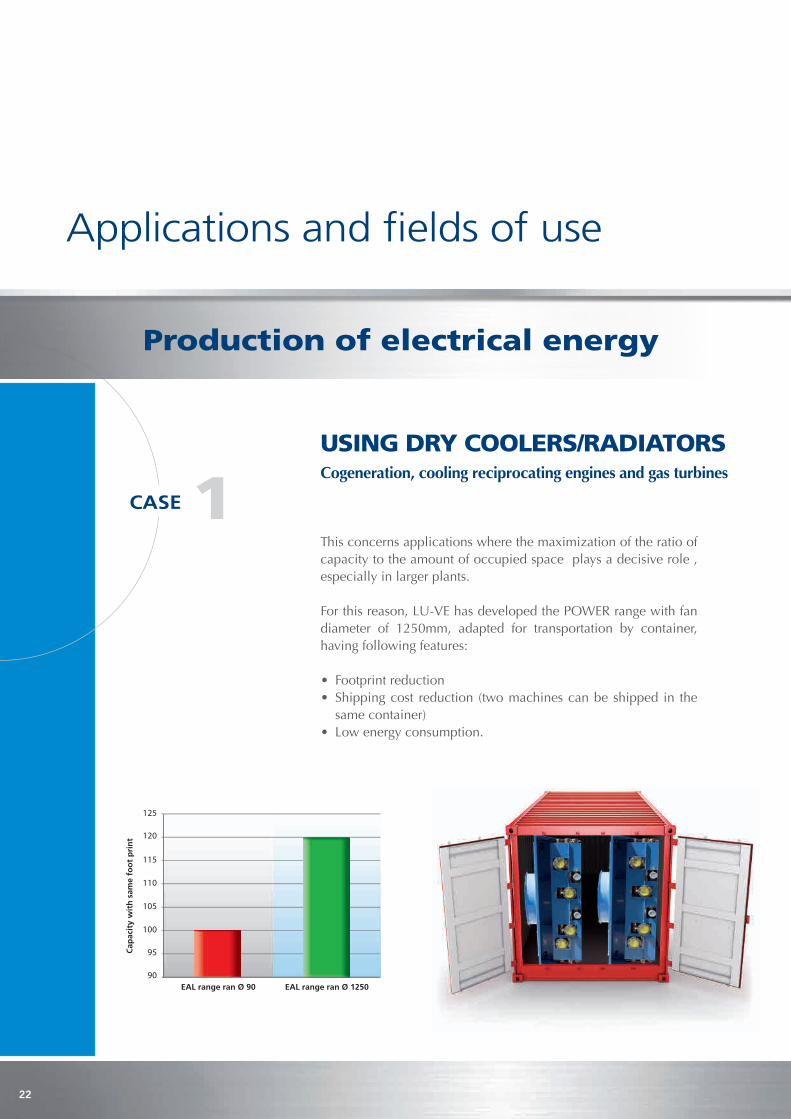
usInG dRy CooleRs/RadIatoRs Cogeneration, cooling reciprocating engines and gas turbines
this concerns applications where the maximization of the ratio of capacity to the amount of occupied space plays a decisive role , especially in larger plants.
for this reason, lu-Ve has developed the poWer range with fan diameter of 1250mm, adapted for transportation by container, having following features:
• Footprint reduction• Shipping cost reduction (two machines can be shipped in the
same container)• Low energy consumption.
Applications and fields of use
90EAL range ran Ø 90 EAL range ran Ø 1250
Cap
acit
y w
ith
sam
e fo
ot
pri
nt
95
100
105
115
120
110
125
1CASE
Production of electrical energy
23
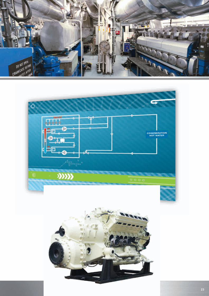
usInG dRy CooleRs/RadIatoRs Cogeneration, cooling reciprocating engines and gas turbines

24
Circuits can be single or with two circuits superimposed with two different temperature levels (lt, Ht), depending on the plant requirements of the circuit to be cooled.
Configuration with two circuits (LT, HT)
Single circuit configuration

25
ELECTRICAL POWER
DISTRICT HEATING
DRYING
TRIGENERATION
HEAT SINK
Turboden ORC units can also be run on saturated steam or superheated water.
HIGH TEMPERATURE
LOW TEMPERATUREDIATHERMIC OIL
DIATHERMIC OIL
BIOMASS BOILER(PRUNINGS, GRAPE POMACE,OLIVE RESIDUE WOOD CHIPS,SAWDUST, BARK, CEREAL HULL ETC.)
usInG CondenseRs FoR oRGanIC FluIds(ORCs)
recently, electrical energy production plants of limited capacity (about 100kW – 5MW) based on organic rankine Cycles operating with organic fluids (siloxanes, HFCs) have become more widespread. for this kind of plant, lu-Ve can offer an air cooled condenser and an internal recuperator coil.
2CASE
Image courtesy of Turboden
Single circuit configuration

26
the special feature of air-cooled condensers for this use is the combination of high capacity of heat transfer, reduced temperature difference between ambient temperature and condensing temperature, and limited energy consumption for the fan ventilation.
27
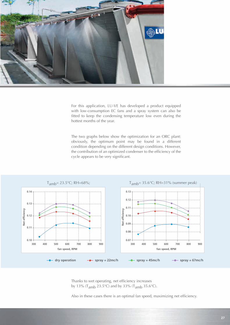
the two graphs below show the optimization for an orC plant: obviously, the optimum point may be found in a different condition depending on the different design conditions. However, the contribution of an optimized condenser to the efficiency of the cycle appears to be very significant.
Thanks to wet operating, net efficiency increases by 13% (tamb 23.5°C) and by 33% (tamb 35.6°C).
Also in these cases there is an optimal fan speed, maximizing net efficiency.
tamb= 23.5°C; rH=68%;
0.10
0.11
0.12
0.13
0.14
Netefficiency
300 400 500 600 700 800 900
fanspeed,RPM
tamb= 35.6°C; rH=31% (summer peak)
0.07
0.09
0.11
0.12
0.13
Netefficiency
300 400 500 600 700 800 900
fanspeed,RPM
0.10
0.08
dryoperation spray=22mc/h spray=45mc/h spray=67mc/h
for this application, lu-Ve has developed a product equipped with low-consumption eC fans and a spray system can also be fitted to keep the condensing temperature low even during the hottest months of the year.

28
the oil and gas industry requires highly reliable products, involving thermodynamic and mechanical design aspects and also great attention to safety considerations. LU-VE can completely comply with all the criteria, thanks also to the ASME Certification Mark with “U” designator of official approval on its machines. one more aspect of great relevance is the use of tubes with reduced diameter (normally 3/8” or ½”) which drastically reduces the internal volume – in other words, the charge of hydrocarbons present inside the heat exchangers.
InnovativeLU-VEproducts
30%
100%
TraditionalaircoolersAPI661
oil & Gas industry and special ateX versions
Internal volume of heat exchangers with same thermal capacity

29
for applications in explosion risk environments, lu-Ve has a specific range equipped with fans which comply with the ATEX Directive 94/9/eC for zones 1 and 2. to guarantee its complete adherence to the official regulations, the machine displays the eX mark. therefore, all the sheet metal parts are treated with a special paint which conducts current, guaranteeing the absolute equipotential of all the surfaces: as an alternative, the machines can also be supplied with stainless steel casings.

30
An area where LU-VE products find a natural position is in the cooling of liquids produced in industrial processes, including both the cooling of machines and also the modulation/dissipation of excess heat. the most modern trends in plant design aim to reach the lowest possible levels of heat to be rejected, so as to minimize the entropic losses of the system. With this objective, LU-VE can supply machines which can operate with very small temperature differences – even negative, if equipped with spray systems.
Cooling liquids in industrial processes

31
the car industry has to frequently update its production and testing facilities, increasing their efficiency, reliability and environmental compatibility. as a result of this urgent necessity, LU-VE has become the privileged supplier to the most important European car manufactures, especially concerning the plant serving the climatic rooms dedicated to testing vehicles and related components. the key to success has always been lu-Ve’s ability to offer technologically advanced solutions, capable of guaranteeing the best ratio of performance to cost calculated over the entire operating life of the plant. Below, some data relative to the consumption of energy and water for a large-scale plant in this sector.
120.000
100.000
80.000
60.000
40.000
20.000
178 370 252 250 356 1473 1910 1611 2360
HOURS FOR PERIOD
kWh
TOTAL ENERGY CONSUMPTION FOR PERIOD
4000
3500
3000
2500
2000
1500
1000
500
034.0 26.5 24.0 21.8 19.8 17.0 12.9 7.2 0.2
AIR TEMPERATURE DISTRIBUTION °C
m3
TOTAL WATER CONSUMPTION FOR PERIOD
AMBIENT TEMPERATURE IN EACH PERIOD (°C)
No
. HO
UR
S IN
EA
CH
PE
RIO
D 1000090008000
7000
6000
5000
4000
3000
2000
1000
01.0 2.0 3.0 4.0 5.0 6.0 7.0 8.0 9.0 10.0
3000
2500
2000
1500
1000
500
0
DISTRIBUTIONCUMULATIVE
AMBIENT TEMPERATURE DISTRIBUTION
No
.HO
UR
S IN
EA
CH
PE
RIO
D
(cum
ulat
ive)
(dis
trib
utio
n)
automotive industry

32
waste treatment plants
In modern european cities, waste treatment is now considered as an industry which is capable of transforming refuse materials into new products or of extracting energy from their combustion, often combined with a district heating system. this sector requires large-capacity dry coolers which have to comply with severe official standards and regulations in order to ensure maximum reliability of the product over time. The LU-VE “V”-bank units with either copper or stainless steel tubes are used in the most up-to-date facilities throughout the Continent.

33
the production of chemical compounds for the pharmaceutical and cosmetics industries has special requirements for dry coolers which respect the environment and at the same time guarantee the very highest hygiene standards: the series of units fitted with Dry and spray® systems, unlike the common evaporative towers, apart from not producing unsightly vapour plumes, has been designed for this precise sector. Most importantly, the water is not recirculated; there is no drain tray collecting the misted water which once sprayed onto the fins (mainly) evaporates or descends down the fins and drips onto the ground where it is disposed of as rainwater.In addition, the sprayed water is a carefully treated and purified liquid; this therefore excludes any possibility of the formation of deposits and biofilm – the typical zone where bacterial colonies grow. Water droplets are not dragged out by the airflow which, after passing through the heat transfer surfaces, is expelled into the atmosphere by the fans. this is ensured by the correct balance of airflow and misted water. It is also verified by sophisticated experimental measurements. In confirmation of its quality and safety, the DRY and SPRAY® product has obtained the Certificate of Safety and Hygiene issued by the prestigious Domatec laboratory in Germany.
Chemical and pharmaceutical industry
34
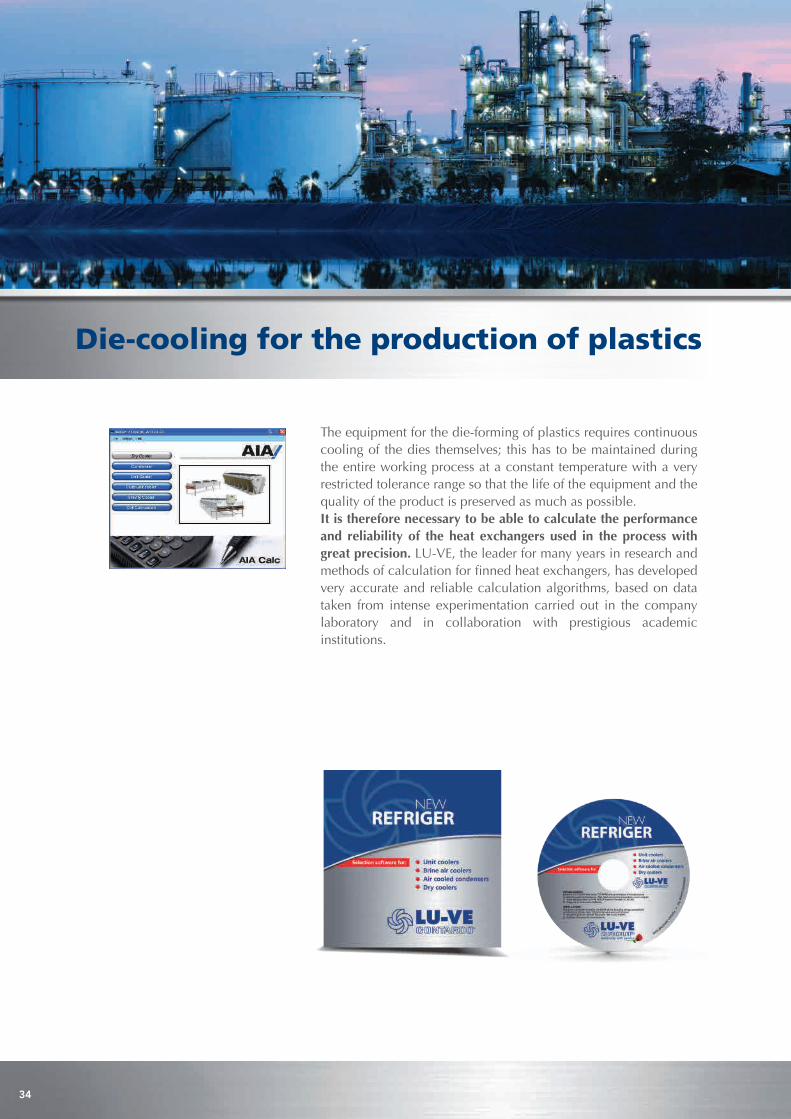
die-cooling for the production of plastics
the equipment for the die-forming of plastics requires continuous cooling of the dies themselves; this has to be maintained during the entire working process at a constant temperature with a very restricted tolerance range so that the life of the equipment and the quality of the product is preserved as much as possible. It is therefore necessary to be able to calculate the performance and reliability of the heat exchangers used in the process with great precision. lu-Ve, the leader for many years in research and methods of calculation for finned heat exchangers, has developed very accurate and reliable calculation algorithms, based on data taken from intense experimentation carried out in the company laboratory and in collaboration with prestigious academic institutions.

35
all products are guaranteed to provide the performance levels indicated in our catalogues, and all standard ranges are certified by Eurovent.
the tests standards applied to the machines are:
ENV 327 for heat exchange capacity of air-cooled condensers ENV 1048 for heat exchange capacity of dry coolers EN 13487 for the measurement of sound power level of condensers and dry coolers.
to ensure that the indicated performance levels are achieved, the products must be correctly installed in line with the general standards of best technical practice and following the instructions in the company manuals for use and maintenance.
Performance
the heat exchangers are designed and constructed in compliance with the standards and regulations in force within the european union listed here:
• Machinery Directive 2006/42/EC • Pressure Equipment Directive (PED) 97/23/EC • Electromagnetic Compatibility Directive (EMC) 2004/108/EC • Low Voltage Directive (LVD) 2006/95/EC
It is also possible on request to have machines sized according to the standard asMe VIII div. I, approved by asMe u stamp.
Manufacturing standards

LU-VES.p.A.Via Caduti della Liberazione, 53 21040 Uboldo (Va) - ItalyTel: +39 02 96716.1e-mail: [email protected] www.luve.it
30189564 -
05/1
3
leadership with passion
LU-VESwedenABSödra Industrivägen 2-4. SE-374 50Asarum - SwedenTel: +46 454 334 00www.aia.se
www.luve.it