Embed Size (px)
Citation preview
K34 K35
K
Dril
ling
Dril
ling
K
MagicDrill DRX
DRX enables stable and efficient drilling
Three chipbreaker types
Twisted Coolant Holes technology design enables
Better chip evacuation through the flute space of the internal cutting edge
1.25 times higher cooling performance
Superior Chip Evacuation
Covers a variety of workpiece materials
Economical 4 edged type2 inner pocket cutting edges and 2 outer pocket cutting edges
The problem of sticky chip trouble when machining stainless
steel or low carbon steel workpieces is solved.
Long entangled chips (Competitor A)
Chips by SM chipbreaker (SUS304)
The special alloy enables toolholder stability and increased reliability.
Twisted Coolant Holes
Positioning of outer edge and inner edge
Conventional tools
Inner edge side
Inner edge sideOuter edge side
Outer edge side
Single coolant hole
Double coolant hole
Inner edge
Inner edge
Outer edge
Outer edge
Inner edge
Outer edge
GM ChipbreakerCarbon Steel, Cast Iron
General Purpose
GH ChipbreakerHard materials,
interrupted drillingTough Edge
SM ChipbreakerStainless Steel,
Low Carbon Steel and Non-ferrous Metals
Sharp cutting for deeper drilling
DRA
DRC
DRX
DRS
DRZ
DRW
K-edited.indd 34 25.08.2016 15:39:12
K34 K35
K
Dril
ling
Dril
ling
K
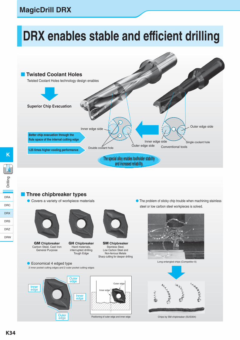
Four Insert Grades(PR1230:for Steel, PR1225:for Stainless Steel / Low Carbon Steel, PR1210:for Cast Iron, GW15:for Non-ferrous Metals)
MEGACOAT is used to enable longer Tool Life
Better wear resistance than competitor BAchieving long Tool Life
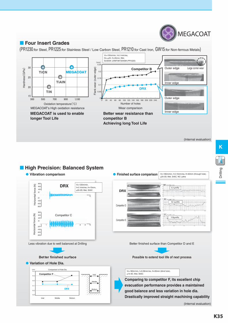
Vibration comparison Finished surface comparison
Less vibration due to well balanced at Drilling Better finished surface than Competitor D and E
Better finished surface Possible to extend tool life of next process
Comparing to competitor F, its excellent chip
evacuation performance provides a maintained
good balance and less variation in hole dia.
Drastically improved straight machining capability
Vc=180m/min, f=0.08mm/rev, H=56mm (blind hole),φ14-4D, Wet, S50C
Vc=180m/min, f=0.15mm/rev, H=60mm (through hole),φ20-3D, Wet, S45C, NC Lathe
MEGACOAT's High oxidation resistance Wear comparison
High Precision: Balanced System
Variation of Hole Dia.
DRX
Competitor D
Competitor E
TiCN
TiAlN
TiN
MEGACOAT
Har
dnes
s(G
Pa)
Oxidation temperature(°C) Number of holes
Outer edge Large corner wear
Inner edge
Outer edge
Inner edge
Fla
nk w
ear
(out
er e
dge)
0 20 40 60 80 100 120 140 160 180 200 220 2400
0.05
0.1
0.15
0.2
0.25(mm)
Competitor B
DRX
1
800
600
400
200
-200
-400
-600
-800
02 3 4 5 6 7 8 9 10
1
800
600
400
200
-200
-400
-600
-800
02 3 4 5 6 7 8 9 10
DRX
Competitor C
Hor
izon
tal f
orce
(N)
Hor
izon
tal f
orce
(N)
Inlet Middle Bottom
Comparison of Hole Dia.14.4(mm)
14.3
14.2
14.1
14.0
13.9
Competitor F
DRX Bottom
Middle
Inlet
Vc=120m/min,f=0.1mm/rev, H=15mm,φ20-3D, Wet, S55C
Vc=150m/min, f=0.1mm/rev,Dc=φ20, H=35mm, Wet,SUS304: ZXMT06T204SM (PR1225)
(Internal evaluation)
(Internal evaluation)
6.1μmRz
10.1μmRz
17.6μmRz
MEGACOAT
K-edited.indd 35 25.08.2016 15:39:14
K36 K37
K
Dril
ling
Dril
ling
K
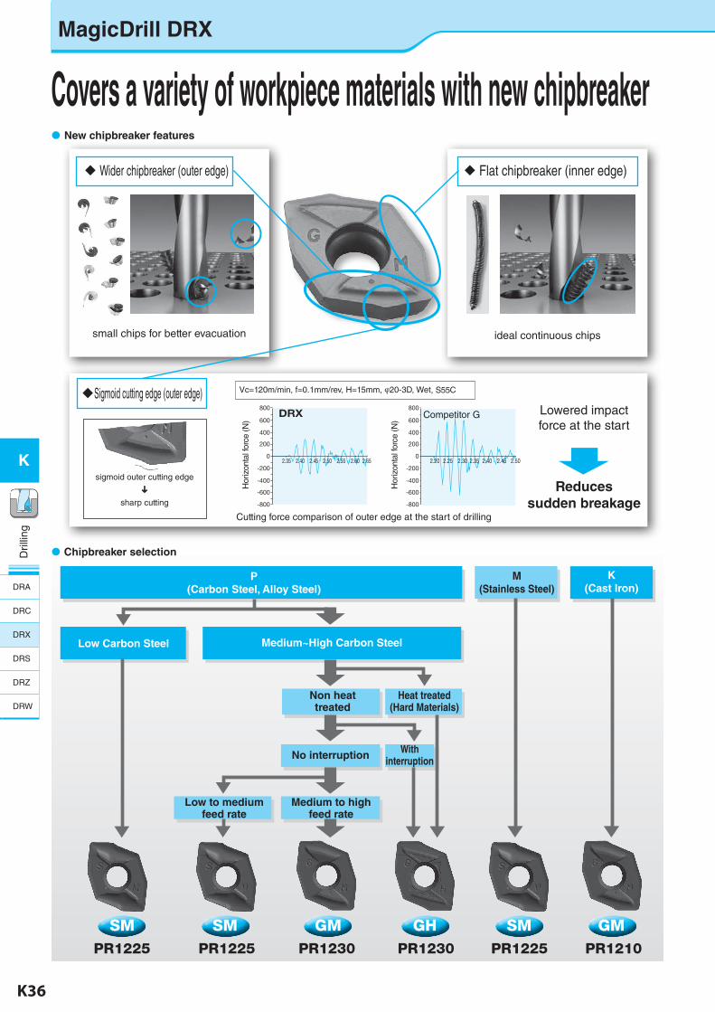
Medium~High Carbon Steel
Heat treated(Hard Materials)
No interruption
M(Stainless Steel)
Low to medium feed rate
Medium to high feed rate
K(Cast Iron)
Non heat treated
With interruption
Covers a variety of workpiece materials with new chipbreaker New chipbreaker features
Wider chipbreaker (outer edge) Flat chipbreaker (inner edge)
Sigmoid cutting edge (outer edge)
Chipbreaker selection
small chips for better evacuation ideal continuous chips
DRX800
600
400
200
2.40 2.452.35 2.50 2.55 2.60 2.650
-200
-400
-600
-800
800
600
400
200
2.20 2.25 2.30 2.35 2.40 2.45 2.500
-200
-400
-600
-800
SM SM GM GH SM GMPR1225 PR1225 PR1230 PR1230 PR1225 PR1210
sigmoid outer cutting edge
sharp cutting
Lowered impact force at the start
Reduces sudden breakage
Cutting force comparison of outer edge at the start of drilling
Competitor G
P(Carbon Steel, Alloy Steel)
Low Carbon Steel
Vc=120m/min, f=0.1mm/rev, H=15mm, φ20-3D, Wet, S55C
Hor
izon
tal f
orce
(N)
Hor
izon
tal f
orce
(N)
MagicDrill DRX
DRA
DRC
DRX
DRS
DRZ
DRW
K-edited.indd 36 25.08.2016 15:39:17
K36 K37
K
Dril
ling
Dril
ling
K
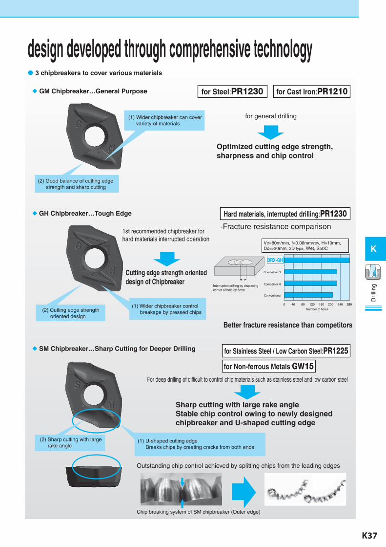
1st recommended chipbreaker for hard materials interrupted operation
Vc=80m/min, f=0.08mm/rev, H=10mm,Dc=φ20mm, 3D type, Wet, S50C
Competitor G
Competitor H
Conventional
Number of holes
Covers a variety of workpiece materials with new chipbreaker design developed through comprehensive technology 3 chipbreakers to cover various materials
GM Chipbreaker…General Purpose
GH Chipbreaker…Tough Edge
(1) Wider chipbreaker can cover variety of materials
(2) Good balance of cutting edge strength and sharp cutting
for Steel:PR1230 for Cast Iron:PR1210
for general drilling
Optimized cutting edge strength, sharpness and chip control
Hard materials, interrupted drilling:PR1230·Fracture resistance comparison
SM Chipbreaker…Sharp Cutting for Deeper Drilling for Stainless Steel / Low Carbon Steel:PR1225
Sharp cutting with large rake angle Stable chip control owing to newly designed chipbreaker and U-shaped cutting edge
(1) Wider chipbreaker control breakage by pressed chips
Cutting edge strength oriented design of Chipbreaker
For deep drilling of difficult to control chip materials such as stainless steel and low carbon steel
Interrupted drilling by displacing center of hole by 8mm
Outstanding chip control achieved by splitting chips from the leading edges
Chip breaking system of SM chipbreaker (Outer edge)
(2) Cutting edge strength oriented design
(2) Sharp cutting with large rake angle
(1) U-shaped cutting edge Breaks chips by creating cracks from both ends
Better fracture resistance than competitors
for Non-ferrous Metals:GW15
K-edited.indd 37 25.08.2016 15:39:17
K38 K39
K
Dril
ling
Dril
ling
K
: Std. Item
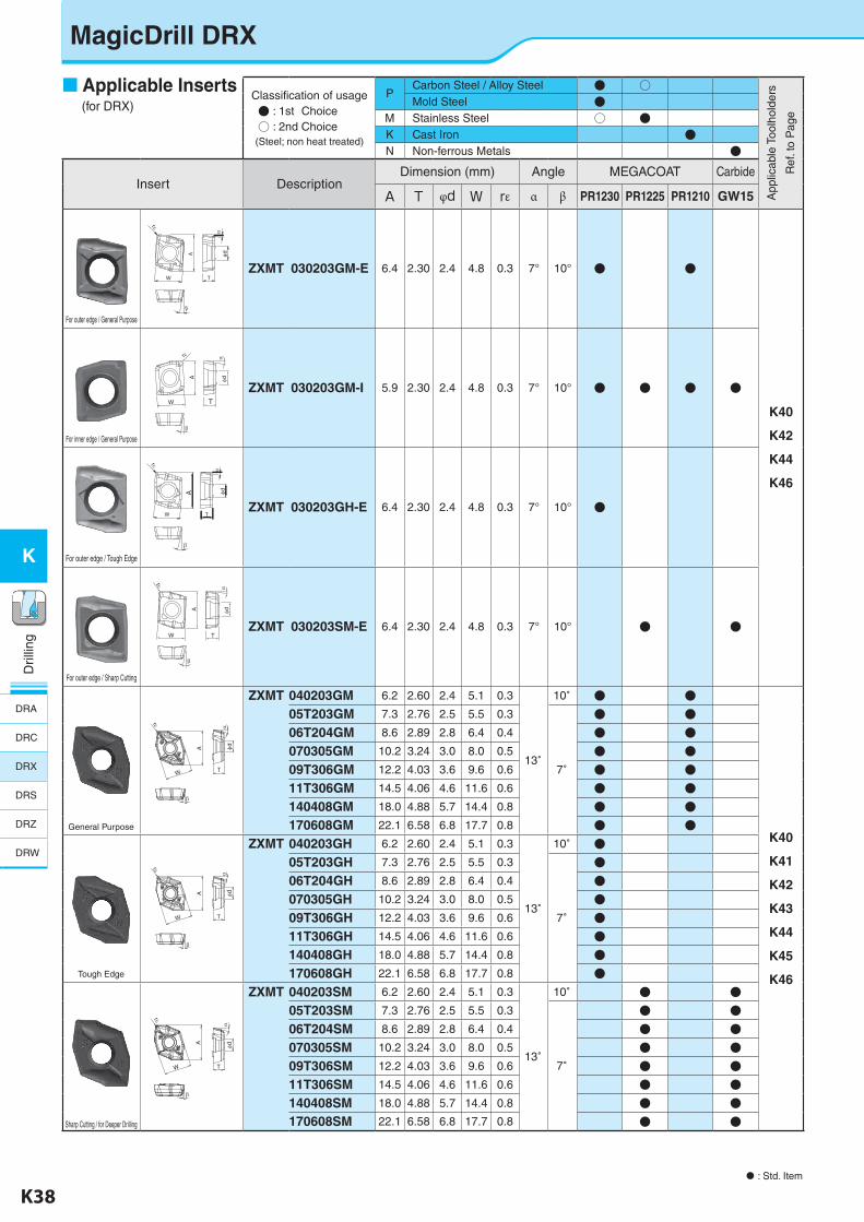
Classification of usage● : 1st Choice○ : 2nd Choice(Steel; non heat treated)
PCarbon Steel / Alloy Steel ● ○
App
licab
le T
oolh
olde
rs
Ref
. to
Pag
e
Mold Steel ●M Stainless Steel ○ ●K Cast Iron ●N Non-ferrous Metals ●
Insert DescriptionDimension (mm) Angle MEGACOAT Carbide
A T φd W rε α β PR1230 PR1225 PR1210 GW15
For outer edge / General Purpose
ZXMT 030203GM-E 6.4 2.30 2.4 4.8 0.3 7° 10° ● ●
K40
K42
K44
K46
For inner edge / General Purpose
A
W
r
T
d
ZXMT 030203GM-I 5.9 2.30 2.4 4.8 0.3 7° 10° ● ● ● ●
For outer edge / Tough Edge
ZXMT 030203GH-E 6.4 2.30 2.4 4.8 0.3 7° 10° ●
For outer edge / Sharp Cutting
W
A
r
T
d
ZXMT 030203SM-E 6.4 2.30 2.4 4.8 0.3 7° 10° ● ●
A φd
W
rε
T
β
α
ZXMT 040203GM 6.2 2.60 2.4 5.1 0.3
13゚
10゚ ● ●
K40
K41
K42
K43
K44
K45
K46
05T203GM 7.3 2.76 2.5 5.5 0.3
7゚
● ●06T204GM 8.6 2.89 2.8 6.4 0.4 ● ●070305GM 10.2 3.24 3.0 8.0 0.5 ● ●09T306GM 12.2 4.03 3.6 9.6 0.6 ● ●11T306GM 14.5 4.06 4.6 11.6 0.6 ● ●140408GM 18.0 4.88 5.7 14.4 0.8 ● ●170608GM 22.1 6.58 6.8 17.7 0.8 ● ●
T
A
W
rε
α
β
φd
ZXMT 040203GH 6.2 2.60 2.4 5.1 0.3
13゚
10゚ ●05T203GH 7.3 2.76 2.5 5.5 0.3
7゚
●06T204GH 8.6 2.89 2.8 6.4 0.4 ●070305GH 10.2 3.24 3.0 8.0 0.5 ●09T306GH 12.2 4.03 3.6 9.6 0.6 ●11T306GH 14.5 4.06 4.6 11.6 0.6 ●140408GH 18.0 4.88 5.7 14.4 0.8 ●170608GH 22.1 6.58 6.8 17.7 0.8 ●
A
W T
rε
α
β
φd
ZXMT 040203SM 6.2 2.60 2.4 5.1 0.3
13゚
10゚ ● ●05T203SM 7.3 2.76 2.5 5.5 0.3
7゚
● ●06T204SM 8.6 2.89 2.8 6.4 0.4 ● ●070305SM 10.2 3.24 3.0 8.0 0.5 ● ●09T306SM 12.2 4.03 3.6 9.6 0.6 ● ●11T306SM 14.5 4.06 4.6 11.6 0.6 ● ●140408SM 18.0 4.88 5.7 14.4 0.8 ● ●170608SM 22.1 6.58 6.8 17.7 0.8 ● ●
W T
A
r
d
W
r
T
A d
MagicDrill DRX
Applicable Inserts (for DRX)
General Purpose
Tough Edge
Sharp Cutting / for Deeper Drilling
DRA
DRC
DRX
DRS
DRZ
DRW
K-edited.indd 38 25.08.2016 15:39:23
K38 K39
K
Dril
ling
Dril
ling
K
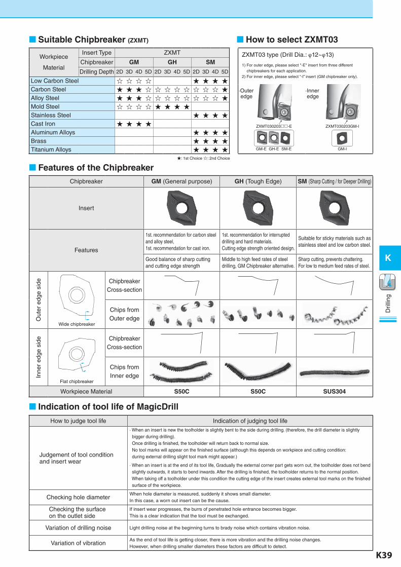
Suitable Chipbreaker (ZXMT)
Workpiece
Material
Insert Type ZXMT
Chipbreaker GM GH SM
Drilling Depth 2D 3D 4D 5D 2D 3D 4D 5D 2D 3D 4D 5D
Low Carbon Steel ☆ ☆ ☆ ☆ ★ ★ ★ ★Carbon Steel ★ ★ ★ ☆ ☆ ☆ ☆ ☆ ☆ ☆ ☆ ★Alloy Steel ★ ★ ★ ☆ ☆ ☆ ☆ ☆ ☆ ☆ ☆ ★Mold Steel ☆ ☆ ☆ ☆ ★ ★ ★ ★Stainless Steel ★ ★ ★ ★Cast Iron ★ ★ ★ ★Aluminum Alloys ★ ★ ★ ★Brass ★ ★ ★ ★Titanium Alloys ★ ★ ★ ★
★: 1st Choice ☆: 2nd Choice
Features of the ChipbreakerChipbreaker GM (General purpose) GH (Tough Edge) SM (Sharp Cutting / for Deeper Drilling)
Insert
Features
1st. recommendation for carbon steel and alloy steel,1st. recommendation for cast iron.
1st. recommendation for interrupted drilling and hard materials.Cutting edge strength oriented design.
Suitable for sticky materials such as stainless steel and low carbon steel.
Good balance of sharp cutting and cutting edge strength
Middle to high feed rates of steel drilling, GM Chipbreaker alternative.
Sharp cutting, prevents chattering. For low to medium feed rates of steel.
Out
er e
dge
side
Wide chipbreaker
Chipbreaker Cross-section
Chips from Outer edge
Inne
r ed
ge s
ide
Flat chipbreaker
Chipbreaker Cross-section
Chips from Inner edge
Workpiece Material S50C S50C SUS304
Indication of tool life of MagicDrill
How to judge tool life Indication of judging tool life
Judgement of tool condition and insert wear
· When an insert is new the toolholder is slightly bent to the side during drilling. (therefore, the drill diameter is slightly bigger during drilling). Once drilling is finished, the toolholder will return back to normal size. No tool marks will appear on the finished surface (although this depends on workpiece and cutting condition: during external drilling slight tool mark might appear.)
· When an insert is at the end of its tool life, Gradually the external corner part gets worn out, the toolholder does not bend slightly outwards, it starts to bend inwards. After the drilling is finished, the toolholder returns to the normal position. When taking off a toolholder under this condition the cutting edge of the insert creates external tool marks on the finished surface of the workpiece.
Checking hole diameterWhen hole diameter is measured, suddenly it shows small diameter.In this case, a worn out insert can be the cause.
Checking the surface on the outlet side
If insert wear progresses, the burrs of penetrated hole entrance becomes bigger.This is a clear indication that the tool must be exchanged.
Variation of drilling noise Light drilling noise at the beginning turns to brady noise which contains vibration noise.
Variation of vibrationAs the end of tool life is getting closer, there is more vibration and the drilling noise changes.However, when drilling smaller diameters these factors are difficult to detect.
How to select ZXMT03
ZXMT03 type (Drill Dia.: φ12~φ13)
1) For outer edge, please select "-E" insert from three different chipbreakers for each application.2) For inner edge, please select “-I” insert (GM chipbreaker only).
·Outer edge
·Inner edge
ZXMT030203GM-IZXMT030203-E
GM-IGH-EGM-E SM-E
→ →
K-edited.indd 39 25.08.2016 15:39:25
K40 K41
K
Dril
ling
Dril
ling
K
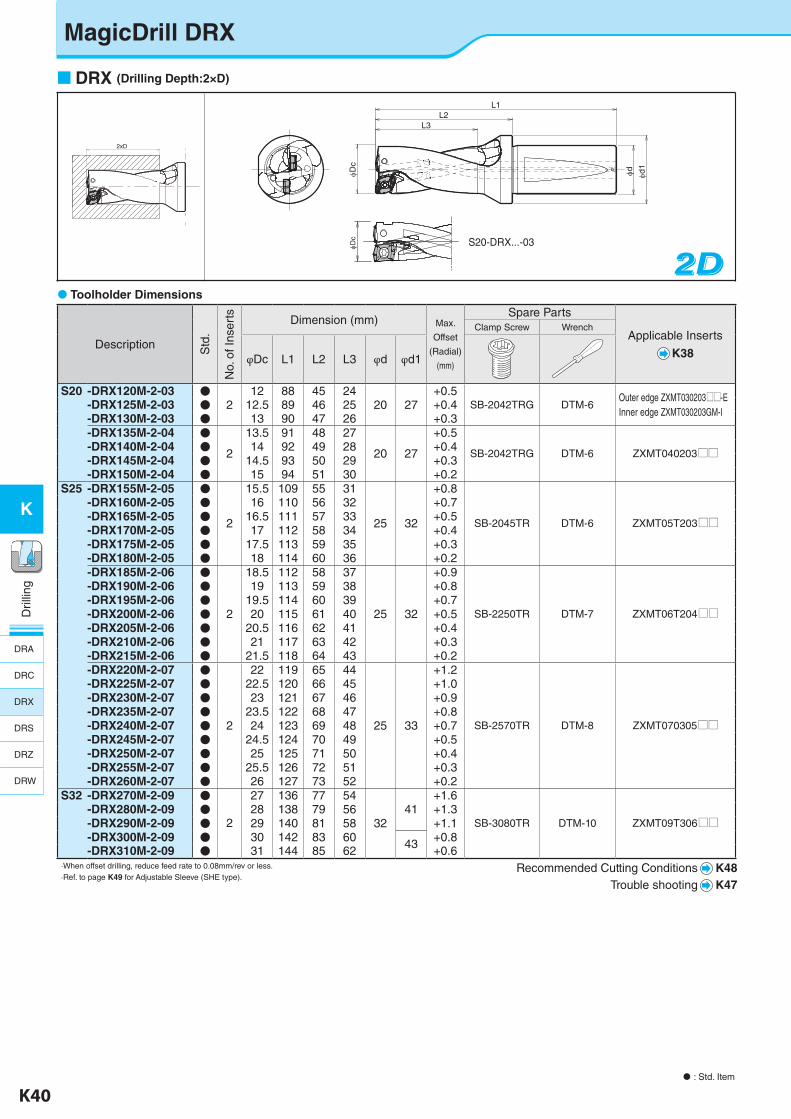
Toolholder Dimensions
Description Std
.
No.
of I
nser
ts Dimension (mm) Max.
Offset
(Radial)
(mm)
Spare Parts
Applicable Inserts
K38
Clamp Screw Wrench
φDc L1 L2 L3 φd φd1
S20 -DRX120M-2-03 ●2
12 88 45 2420 27
+0.5SB-2042TRG DTM-6
Outer edge ZXMT030203UU-EInner edge ZXMT030203GM-I
-DRX125M-2-03 ● 12.5 89 46 25 +0.4-DRX130M-2-03 ● 13 90 47 26 +0.3-DRX135M-2-04 ●
2
13.5 91 48 27
20 27
+0.5
SB-2042TRG DTM-6 ZXMT040203UU-DRX140M-2-04 ● 14 92 49 28 +0.4-DRX145M-2-04 ● 14.5 93 50 29 +0.3-DRX150M-2-04 ● 15 94 51 30 +0.2
S25 -DRX155M-2-05 ●
2
15.5 109 55 31
25 32
+0.8
SB-2045TR DTM-6 ZXMT05T203UU
-DRX160M-2-05 ● 16 110 56 32 +0.7-DRX165M-2-05 ● 16.5 111 57 33 +0.5-DRX170M-2-05 ● 17 112 58 34 +0.4-DRX175M-2-05 ● 17.5 113 59 35 +0.3-DRX180M-2-05 ● 18 114 60 36 +0.2-DRX185M-2-06 ●
2
18.5 112 58 37 +0.9-DRX190M-2-06 ● 19 113 59 38 +0.8-DRX195M-2-06 ● 19.5 114 60 39 +0.7-DRX200M-2-06 ● 20 115 61 40 25 32 +0.5 SB-2250TR DTM-7 ZXMT06T204UU-DRX205M-2-06 ● 20.5 116 62 41 +0.4-DRX210M-2-06 ● 21 117 63 42 +0.3-DRX215M-2-06 ● 21.5 118 64 43 +0.2-DRX220M-2-07 ●
2
22 119 65 44 +1.2-DRX225M-2-07 ● 22.5 120 66 45 +1.0-DRX230M-2-07 ● 23 121 67 46 +0.9-DRX235M-2-07 ● 23.5 122 68 47 +0.8-DRX240M-2-07 ● 24 123 69 48 25 33 +0.7 SB-2570TR DTM-8 ZXMT070305UU-DRX245M-2-07 ● 24.5 124 70 49 +0.5-DRX250M-2-07 ● 25 125 71 50 +0.4-DRX255M-2-07 ● 25.5 126 72 51 +0.3-DRX260M-2-07 ● 26 127 73 52 +0.2
S32 -DRX270M-2-09 ●
2
27 136 77 54 +1.6-DRX280M-2-09 ● 28 138 79 56 41 +1.3-DRX290M-2-09 ● 29 140 81 58 32 +1.1 SB-3080TR DTM-10 ZXMT09T306UU-DRX300M-2-09 ● 30 142 83 60 43 +0.8-DRX310M-2-09 ● 31 144 85 62 +0.6
·When offset drilling, reduce feed rate to 0.08mm/rev or less.·Ref. to page K49 for Adjustable Sleeve (SHE type).
Recommended Cutting Conditions K48Trouble shooting K47
: Std. Item
2D2D2D
2xD
φd1
φdφDc
L3L2
L1
φDc
2xD
φd1
φdφDc
L3L2
L1
φDc
S20-DRX...-03
2xD
φd1
φdφDc
L3L2
L1
φDc
MagicDrill DRX
DRX (Drilling Depth:2×D)
DRA
DRC
DRX
DRS
DRZ
DRW
K-edited.indd 40 25.08.2016 15:39:45
K40 K41
K
Dril
ling
Dril
ling
K
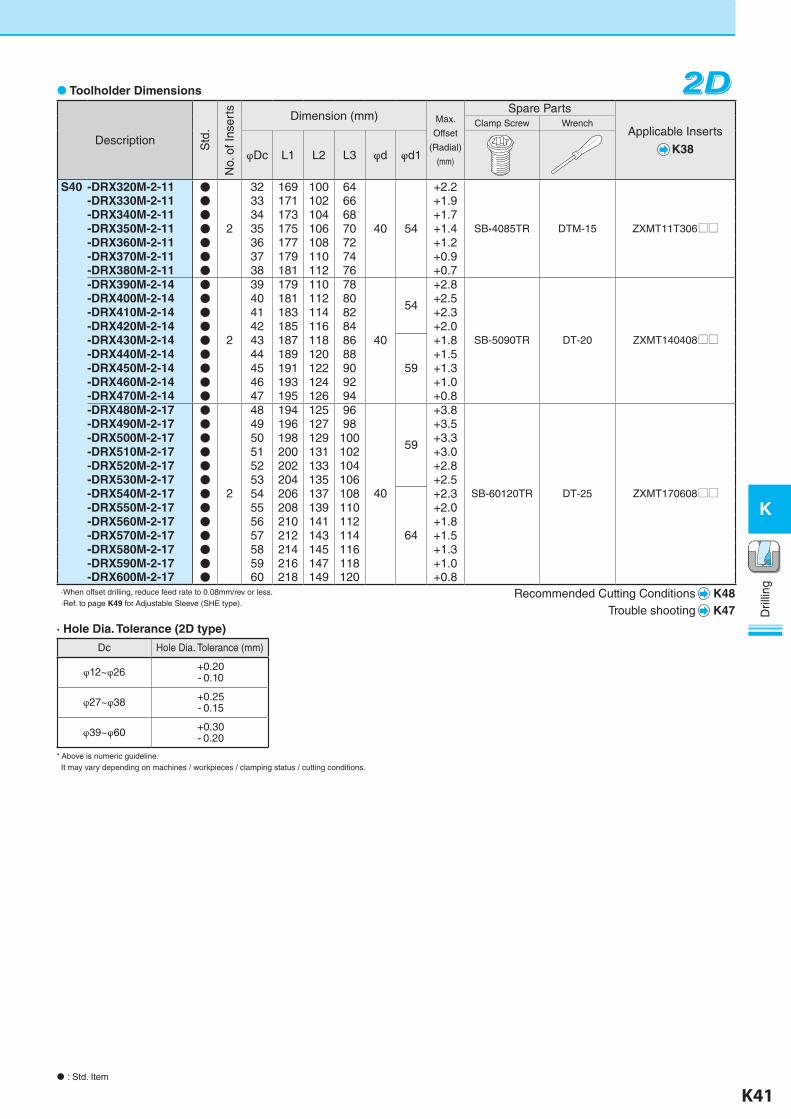
Description Std
.
No.
of I
nser
ts Dimension (mm) Max.
Offset
(Radial)
(mm)
Spare Parts
Applicable Inserts
K38
Clamp Screw Wrench
φDc L1 L2 L3 φd φd1
S40 -DRX320M-2-11 ● 32 169 100 64 +2.2
SB-4085TR DTM-15 ZXMT11T306UU
-DRX330M-2-11 ● 33 171 102 66 +1.9-DRX340M-2-11 ● 34 173 104 68 +1.7-DRX350M-2-11 ● 2 35 175 106 70 40 54 +1.4-DRX360M-2-11 ● 36 177 108 72 +1.2-DRX370M-2-11 ● 37 179 110 74 +0.9-DRX380M-2-11 ● 38 181 112 76 +0.7-DRX390M-2-14 ●
2
39 179 110 78
40
54
+2.8
SB-5090TR DT-20 ZXMT140408UU
-DRX400M-2-14 ● 40 181 112 80 +2.5-DRX410M-2-14 ● 41 183 114 82 +2.3-DRX420M-2-14 ● 42 185 116 84 +2.0-DRX430M-2-14 ● 43 187 118 86
59
+1.8-DRX440M-2-14 ● 44 189 120 88 +1.5-DRX450M-2-14 ● 45 191 122 90 +1.3-DRX460M-2-14 ● 46 193 124 92 +1.0-DRX470M-2-14 ● 47 195 126 94 +0.8-DRX480M-2-17 ●
2
48 194 125 96
40
59
+3.8
SB-60120TR DT-25 ZXMT170608UU
-DRX490M-2-17 ● 49 196 127 98 +3.5-DRX500M-2-17 ● 50 198 129 100 +3.3-DRX510M-2-17 ● 51 200 131 102 +3.0-DRX520M-2-17 ● 52 202 133 104 +2.8-DRX530M-2-17 ● 53 204 135 106 +2.5-DRX540M-2-17 ● 54 206 137 108
64
+2.3-DRX550M-2-17 ● 55 208 139 110 +2.0-DRX560M-2-17 ● 56 210 141 112 +1.8-DRX570M-2-17 ● 57 212 143 114 +1.5-DRX580M-2-17 ● 58 214 145 116 +1.3-DRX590M-2-17 ● 59 216 147 118 +1.0-DRX600M-2-17 ● 60 218 149 120 +0.8
·When offset drilling, reduce feed rate to 0.08mm/rev or less.·Ref. to page K49 for Adjustable Sleeve (SHE type).
2D2D2D
: Std. Item
Recommended Cutting Conditions K48Trouble shooting K47
Toolholder Dimensions
· Hole Dia. Tolerance (2D type)
* Above is numeric guideline. It may vary depending on machines / workpieces / clamping status / cutting conditions.
Dc Hole Dia. Tolerance (mm)
φ12~φ26 +0.20- 0.10
φ27~φ38 +0.25- 0.15
φ39~φ60 +0.30- 0.20
K-edited.indd 41 25.08.2016 15:39:48
K42 K43
K
Dril
ling
Dril
ling
K
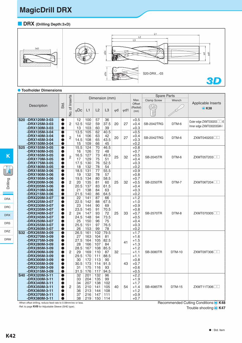
MagicDrill DRX
DRX (Drilling Depth:3×D)
: Std. Item
3D3D3D Toolholder Dimensions
Description Std
.
No.
of I
nser
ts Dimension (mm)Max. Offset
(Radial)(mm)
Spare Parts
Applicable InsertsK38
Clamp Screw Wrench
φDc L1 L2 L3 φd φd1
S20 -DRX120M-3-03 ●2
12 100 57 3620 27
+0.5SB-2042TRG DTM-6
Outer edge ZXMT030203UU-EInner edge ZXMT030203GM-I
-DRX125M-3-03 ● 12.5 102 59 37.5 +0.4-DRX130M-3-03 ● 13 103 60 39 +0.3-DRX135M-3-04 ●
2
13.5 105 62 40.5
20 27
+0.5
SB-2042TRG DTM-6 ZXMT040203UU-DRX140M-3-04 ● 14 106 63 42 +0.4-DRX145M-3-04 ● 14.5 108 65 43.5 +0.3-DRX150M-3-04 ● 15 109 66 45 +0.2
S25 -DRX155M-3-05 ●
2
15.5 124 70 46.5
25 32
+0.8
SB-2045TR DTM-6 ZXMT05T203UU
-DRX160M-3-05 ● 16 126 72 48 +0.7-DRX165M-3-05 ● 16.5 127 73 49.5 +0.5-DRX170M-3-05 ● 17 129 75 51 +0.4-DRX175M-3-05 ● 17.5 130 76 52.5 +0.3-DRX180M-3-05 ● 18 132 78 54 +0.2-DRX185M-3-06 ●
2
18.5 131 77 55.5
25 32
+0.9
SB-2250TR DTM-7 ZXMT06T204UU
-DRX190M-3-06 ● 19 132 78 57 +0.8-DRX195M-3-06 ● 19.5 134 80 58.5 +0.7-DRX200M-3-06 ● 20 135 81 60 +0.5-DRX205M-3-06 ● 20.5 137 83 61.5 +0.4-DRX210M-3-06 ● 21 138 84 63 +0.3-DRX215M-3-06 ● 21.5 140 86 64.5 +0.2-DRX220M-3-07 ●
2
22 141 87 66
25 33
+1.2
SB-2570TR DTM-8 ZXMT070305UU
-DRX225M-3-07 ● 22.5 142 88 67.5 +1.0-DRX230M-3-07 ● 23 144 90 69 +0.9-DRX235M-3-07 ● 23.5 145 91 70.5 +0.8-DRX240M-3-07 ● 24 147 93 72 +0.7-DRX245M-3-07 ● 24.5 148 94 73.5 +0.5-DRX250M-3-07 ● 25 150 96 75 +0.4-DRX255M-3-07 ● 25.5 151 97 76.5 +0.3-DRX260M-3-07 ● 26 153 99 78 +0.2
S32 -DRX265M-3-09 ●
2
26.5 161 102 79.5
32
41
+1.7
SB-3080TR DTM-10 ZXMT09T306UU
-DRX270M-3-09 ● 27 163 104 81 +1.6-DRX275M-3-09 ● 27.5 164 105 82.5 +1.5-DRX280M-3-09 ● 28 166 107 84 +1.3-DRX285M-3-09 ● 28.5 167 108 85.5 +1.2-DRX290M-3-09 ● 29 169 110 87 +1.1-DRX295M-3-09 ● 29.5 170 111 88.5
43
+1.1-DRX300M-3-09 ● 30 172 113 90 +0.8-DRX305M-3-09 ● 30.5 173 114 91.5 +0.7-DRX310M-3-09 ● 31 175 116 93 +0.6-DRX315M-3-09 ● 31.5 176 117 94.5 +0.5
S40 -DRX320M-3-11 ●
2
32 201 132 96
40 54
+2.2
SB-4085TR DTM-15 ZXMT11T306UU
-DRX330M-3-11 ● 33 204 135 99 +1.9-DRX340M-3-11 ● 34 207 138 102 +1.7-DRX350M-3-11 ● 35 210 141 105 +1.4-DRX360M-3-11 ● 36 213 144 108 +1.2-DRX370M-3-11 ● 37 216 147 111 +0.9-DRX380M-3-11 ● 38 219 150 114 +0.7
·When offset drilling, reduce feed rate to 0.08mm/rev or less.
·Ref. to page K49 for Adjustable Sleeve (SHE type).Recommended Cutting Conditions K48
Trouble shooting K47
3xD
φDc
L3L2
L1
φd φd1
φDc S20-DRX...-03
DRA
DRC
DRX
DRS
DRZ
DRW
K-edited.indd 42 25.08.2016 15:39:50

K42 K43
K
Dril
ling
Dril
ling
K
: Std. Item
Toolholder Dimensions
Description Std
.
No.
of I
nser
ts Dimension (mm)Max. Offset
(Radial)(mm)
Spare Parts
Applicable InsertsK38
Clamp Screw Wrench
φDc L1 L2 L3 φd φd1
S40 -DRX390M-3-14 ●
2
39 218 149 117
40
54
+2.8
SB-5090TR DT-20 ZXMT140408
-DRX400M-3-14 ● 40 221 152 120 +2.5-DRX410M-3-14 ● 41 224 155 123 +2.3-DRX420M-3-14 ● 42 227 158 126 +2.0-DRX430M-3-14 ● 43 230 161 129
59
+1.8-DRX440M-3-14 ● 44 233 164 132 +1.5-DRX450M-3-14 ● 45 236 167 135 +1.3-DRX460M-3-14 ● 46 239 170 138 +1.0-DRX470M-3-14 ● 47 242 173 141 +0.8-DRX480M-3-17 ●
2
48 242 173 144
40
59
+3.8
SB-60120TR DT-25 ZXMT170608
-DRX490M-3-17 ● 49 245 176 147 +3.5-DRX500M-3-17 ● 50 248 179 150 +3.3-DRX510M-3-17 ● 51 251 182 153 +3.0-DRX520M-3-17 ● 52 254 185 156 +2.8-DRX530M-3-17 ● 53 257 188 159 +2.5-DRX540M-3-17 ● 54 260 191 162
64
+2.3-DRX550M-3-17 ● 55 263 194 165 +2.0-DRX560M-3-17 ● 56 266 197 168 +1.8-DRX570M-3-17 ● 57 269 200 171 +1.5-DRX580M-3-17 ● 58 272 203 174 +1.3-DRX590M-3-17 ● 59 275 206 177 +1.0-DRX600M-3-17 ● 60 278 209 180 +0.8
·When offset drilling, reduce feed rate to 0.08mm/rev or less.
·Ref. to page K49 for Adjustable Sleeve (SHE type).
3D3D3D
Recommended Cutting Conditions K48Trouble shooting K47
· Hole Dia. Tolerance (3D type)
* Above is numeric guideline. It may vary depending on machines / workpieces / clamping status / cutting conditions.
Dc Hole Dia. Tolerance (mm)
φ12~φ26 +0.20- 0.10
φ26.5~φ38 + 0.25- 0.15
φ39~φ60 + 0.30- 0.20
K-edited.indd 43 25.08.2016 15:39:52
K44 K45
K
Dril
ling
Dril
ling
K
: Std. Item
Toolholder Dimensions
Description Std
.
No.
of I
nser
ts Dimension (mm)Max. Offset
(Radial)(mm)
Spare Parts
Applicable InsertsK38
Clamp Screw Wrench
φDc L1 L2 L3 φd φd1
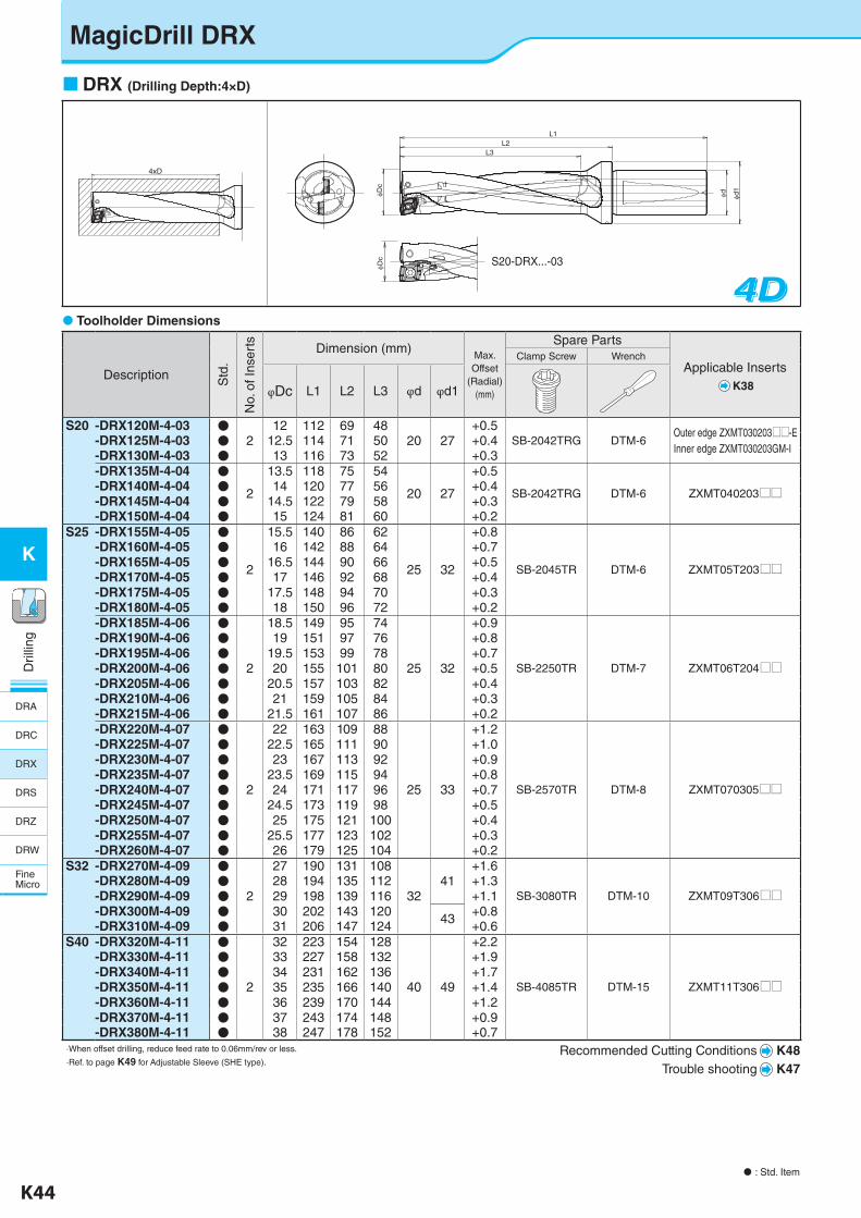
S20 -DRX120M-4-03 ●2
12 112 69 4820 27
+0.5SB-2042TRG DTM-6
Outer edge ZXMT030203UU-EInner edge ZXMT030203GM-I
-DRX125M-4-03 ● 12.5 114 71 50 +0.4-DRX130M-4-03 ● 13 116 73 52 +0.3-DRX135M-4-04 ●
2
13.5 118 75 54
20 27
+0.5
SB-2042TRG DTM-6 ZXMT040203UU-DRX140M-4-04 ● 14 120 77 56 +0.4-DRX145M-4-04 ● 14.5 122 79 58 +0.3-DRX150M-4-04 ● 15 124 81 60 +0.2
S25 -DRX155M-4-05 ●
2
15.5 140 86 62
25 32
+0.8
SB-2045TR DTM-6 ZXMT05T203UU
-DRX160M-4-05 ● 16 142 88 64 +0.7-DRX165M-4-05 ● 16.5 144 90 66 +0.5-DRX170M-4-05 ● 17 146 92 68 +0.4-DRX175M-4-05 ● 17.5 148 94 70 +0.3-DRX180M-4-05 ● 18 150 96 72 +0.2-DRX185M-4-06 ●
2
18.5 149 95 74
25 32
+0.9
SB-2250TR DTM-7 ZXMT06T204UU
-DRX190M-4-06 ● 19 151 97 76 +0.8-DRX195M-4-06 ● 19.5 153 99 78 +0.7-DRX200M-4-06 ● 20 155 101 80 +0.5-DRX205M-4-06 ● 20.5 157 103 82 +0.4-DRX210M-4-06 ● 21 159 105 84 +0.3-DRX215M-4-06 ● 21.5 161 107 86 +0.2-DRX220M-4-07 ●
2
22 163 109 88
25 33
+1.2
SB-2570TR DTM-8 ZXMT070305UU
-DRX225M-4-07 ● 22.5 165 111 90 +1.0-DRX230M-4-07 ● 23 167 113 92 +0.9-DRX235M-4-07 ● 23.5 169 115 94 +0.8-DRX240M-4-07 ● 24 171 117 96 +0.7-DRX245M-4-07 ● 24.5 173 119 98 +0.5-DRX250M-4-07 ● 25 175 121 100 +0.4-DRX255M-4-07 ● 25.5 177 123 102 +0.3-DRX260M-4-07 ● 26 179 125 104 +0.2
S32 -DRX270M-4-09 ●
2
27 190 131 108
3241
+1.6
SB-3080TR DTM-10 ZXMT09T306UU-DRX280M-4-09 ● 28 194 135 112 +1.3-DRX290M-4-09 ● 29 198 139 116 +1.1-DRX300M-4-09 ● 30 202 143 120 43 +0.8-DRX310M-4-09 ● 31 206 147 124 +0.6
S40 -DRX320M-4-11 ●
2
32 223 154 128
40 49
+2.2
SB-4085TR DTM-15 ZXMT11T306UU
-DRX330M-4-11 ● 33 227 158 132 +1.9-DRX340M-4-11 ● 34 231 162 136 +1.7-DRX350M-4-11 ● 35 235 166 140 +1.4-DRX360M-4-11 ● 36 239 170 144 +1.2-DRX370M-4-11 ● 37 243 174 148 +0.9-DRX380M-4-11 ● 38 247 178 152 +0.7
·When offset drilling, reduce feed rate to 0.06mm/rev or less.
·Ref. to page K49 for Adjustable Sleeve (SHE type).Recommended Cutting Conditions K48
Trouble shooting K47
4D4D4D
DRX (Drilling Depth:4×D)
φDc
L3L2
L1
φd φd1
φDc
4xD
S20-DRX...-03
MagicDrill DRX
DRA
DRC
DRX
DRS
DRZ
DRW
FineMicro
K-edited.indd 44 25.08.2016 15:39:55
K44 K45
K
Dril
ling
Dril
ling
K
: Std. Item
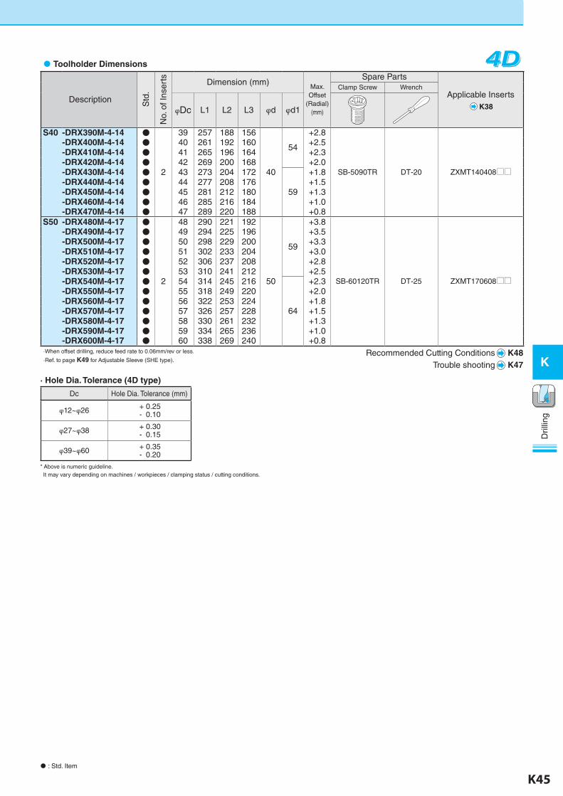
4D4D4D Toolholder Dimensions
Description Std
.
No.
of I
nser
ts Dimension (mm)Max. Offset
(Radial)(mm)
Spare Parts
Applicable InsertsK38
Clamp Screw Wrench
φDc L1 L2 L3 φd φd1
S40 -DRX390M-4-14 ●
2
39 257 188 156
40
54
+2.8
SB-5090TR DT-20 ZXMT140408UU
-DRX400M-4-14 ● 40 261 192 160 +2.5-DRX410M-4-14 ● 41 265 196 164 +2.3-DRX420M-4-14 ● 42 269 200 168 +2.0-DRX430M-4-14 ● 43 273 204 172
59
+1.8-DRX440M-4-14 ● 44 277 208 176 +1.5-DRX450M-4-14 ● 45 281 212 180 +1.3-DRX460M-4-14 ● 46 285 216 184 +1.0-DRX470M-4-14 ● 47 289 220 188 +0.8
S50 -DRX480M-4-17 ●
2
48 290 221 192
50
59
+3.8
SB-60120TR DT-25 ZXMT170608UU
-DRX490M-4-17 ● 49 294 225 196 +3.5-DRX500M-4-17 ● 50 298 229 200 +3.3-DRX510M-4-17 ● 51 302 233 204 +3.0-DRX520M-4-17 ● 52 306 237 208 +2.8-DRX530M-4-17 ● 53 310 241 212 +2.5-DRX540M-4-17 ● 54 314 245 216
64
+2.3-DRX550M-4-17 ● 55 318 249 220 +2.0-DRX560M-4-17 ● 56 322 253 224 +1.8-DRX570M-4-17 ● 57 326 257 228 +1.5-DRX580M-4-17 ● 58 330 261 232 +1.3-DRX590M-4-17 ● 59 334 265 236 +1.0-DRX600M-4-17 ● 60 338 269 240 +0.8
·When offset drilling, reduce feed rate to 0.06mm/rev or less.
·Ref. to page K49 for Adjustable Sleeve (SHE type).Recommended Cutting Conditions K48
Trouble shooting K47
· Hole Dia. Tolerance (4D type)
* Above is numeric guideline. It may vary depending on machines / workpieces / clamping status / cutting conditions.
Dc Hole Dia. Tolerance (mm)
φ12~φ26 + 0.25- 0.10
φ27~φ38 + 0.30- 0.15
φ39~φ60 + 0.35- 0.20
K-edited.indd 45 25.08.2016 15:39:56
K46 K47
K
Dril
ling
Dril
ling
K
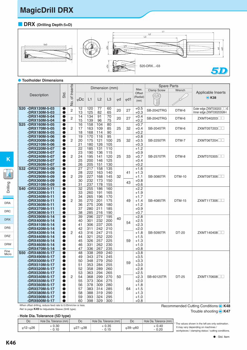
DRX (Drilling Depth:5×D)
Toolholder Dimensions
Description Std
.
No.
of I
nser
ts
Dimension (mm) Max. Offset
(Radial)(mm)
Spare Parts
Applicable InsertsK38
Clamp Screw Wrench
φDc L1 L2 L3 φd φd1
S20 -DRX120M-5-03 ● 2 12 120 77 60 20 27 +0.5 SB-2042TRG DTM-6 Outer edge ZXMT030203UU-EInner edge ZXMT030203GM-I-DRX130M-5-03 ● 13 125 82 65 +0.3
-DRX140M-5-04 ● 2 14 134 91 70 20 27 +0.4 SB-2042TRG DTM-6 ZXMT040203UU-DRX150M-5-04 ● 15 139 96 75 +0.2S25 -DRX160M-5-05 ●
216 158 104 80
25 32+0.7
SB-2045TR DTM-6 ZXMT05T203UU-DRX170M-5-05 ● 17 163 109 85 +0.4-DRX180M-5-05 ● 18 168 114 90 +0.2-DRX190M-5-06 ●
219 170 116 95
25 32+0.8
SB-2250TR DTM-7 ZXMT06T204UU-DRX200M-5-06 ● 20 175 121 100 +0.5-DRX210M-5-06 ● 21 180 126 105 +0.3-DRX220M-5-07 ●
2
22 185 131 110
25 33
+1.2
SB-2570TR DTM-8 ZXMT070305UU-DRX230M-5-07 ● 23 190 136 115 +0.9-DRX240M-5-07 ● 24 195 141 120 +0.7-DRX250M-5-07 ● 25 200 146 125 +0.4-DRX260M-5-07 ● 26 205 151 130 +0.2
S32 -DRX270M-5-09 ●
2
27 217 158 135 +1.6
SB-3080TR DTM-10 ZXMT09T306UU-DRX280M-5-09 ● 28 222 163 140 41 +1.3-DRX290M-5-09 ● 29 227 168 145 32 +1.1-DRX300M-5-09 ● 30 232 173 150 43 +0.8-DRX310M-5-09 ● 31 237 178 155 +0.6
S40 -DRX320M-5-11 ●
2
32 255 186 160
40
49
+2.2
SB-4085TR DTM-15 ZXMT11T306UU
-DRX330M-5-11 ● 33 260 191 165 +1.9-DRX340M-5-11 ● 34 265 196 170 +1.7-DRX350M-5-11 ● 35 270 201 175 +1.4-DRX360M-5-11 ● 36 275 206 180 +1.2-DRX370M-5-11 ● 37 280 211 185 +0.9-DRX380M-5-11 ● 38 285 216 190 +0.7-DRX390M-5-14 ●
2
39 296 227 195
54
+2.8
SB-5090TR DT-20 ZXMT140408UU
-DRX400M-5-14 ● 40 301 232 200 +2.5-DRX410M-5-14 ● 41 306 237 205 +2.3-DRX420M-5-14 ● 42 311 242 210 +2.0-DRX430M-5-14 ● 43 316 247 215
59
+1.8-DRX440M-5-14 ● 44 321 252 220 +1.5-DRX450M-5-14 ● 45 326 257 225 +1.3-DRX460M-5-14 ● 46 331 262 230 +1.0-DRX470M-5-14 ● 47 336 267 235 +0.8
S50 -DRX480M-5-17 ●
2
48 338 269 240
50
59
+3.8
SB-60120TR DT-25 ZXMT170608UU
-DRX490M-5-17 ● 49 343 274 245 +3.5-DRX500M-5-17 ● 50 348 279 250 +3.3-DRX510M-5-17 ● 51 353 284 255 +3.0-DRX520M-5-17 ● 52 358 289 260 +2.8-DRX530M-5-17 ● 53 363 294 265 +2.5-DRX540M-5-17 ● 54 368 299 270
64
+2.3-DRX550M-5-17 ● 55 373 304 275 +2.0-DRX560M-5-17 ● 56 378 309 280 +1.8-DRX570M-5-17 ● 57 383 314 285 +1.5-DRX580M-5-17 ● 58 388 319 290 +1.3-DRX590M-5-17 ● 59 393 324 295 +1.0-DRX600M-5-17 ● 60 398 329 300 +0.8
·When offset drilling, reduce feed rate to 0.05mm/rev or less.
·Ref. to page K49 for Adjustable Sleeve (SHE type).Recommended Cutting Conditions K48
Trouble shooting K47
5xD
φDc
L3L2
L1
φd φd1
φDc
: Std. Item
· Hole Dia. Tolerance (5D type)Dc Hole Dia. Tolerance (mm) Dc Hole Dia. Tolerance (mm) Dc Hole Dia. Tolerance (mm)
φ12~φ26 + 0.30- 0.10 φ27~φ38 + 0.35
- 0.15 φ39~φ60 + 0.40- 0.20
* The values shown in the left are only estimation. It may vary depending on machines / workpieces / clamping status / cutting conditions.
S20-DRX...-03
MagicDrill DRX
DRA
DRC
DRX
DRS
DRZ
DRW
FineMicro
K-edited.indd 46 25.08.2016 15:39:58
K46 K47
K
Dril
ling
Dril
ling
K
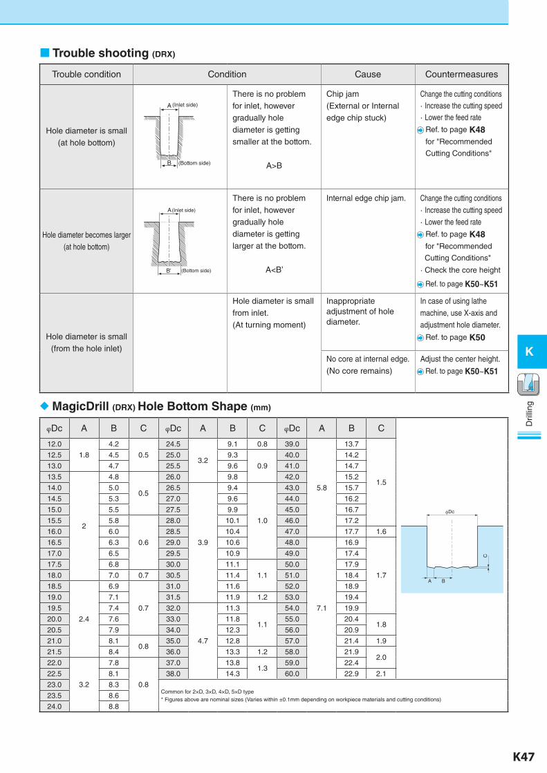
Trouble shooting (DRX)
Trouble condition Condition Cause Countermeasures
Hole diameter is small(at hole bottom)
There is no problem for inlet, however gradually hole diameter is getting smaller at the bottom.
A>B
Chip jam(External or Internal edge chip stuck)
Change the cutting conditions· Increase the cutting speed· Lower the feed rate
Ref. to page K48
for "Recommended
Cutting Conditions"
Hole diameter becomes larger(at hole bottom)
There is no problem for inlet, however gradually hole diameter is getting larger at the bottom.
A<B’
Internal edge chip jam. Change the cutting conditions· Increase the cutting speed· Lower the feed rate
Ref. to page K48
for "Recommended
Cutting Conditions"
· Check the core height
Ref. to page K50~K51
Hole diameter is small(from the hole inlet)
Hole diameter is small from inlet.(At turning moment)
Inappropriate adjustment of hole diameter.
In case of using lathe machine, use X-axis and adjustment hole diameter.
Ref. to page K50
No core at internal edge.(No core remains)
Adjust the center height.
Ref. to page K50~K51
MagicDrill (DRX) Hole Bottom Shape (mm)
φDc A B C φDc A B C φDc A B C
Dc
A B
C
12.0
1.8
4.2
0.5
24.5
3.2
9.1 0.8 39.0
5.8
13.7
1.5
12.5 4.5 25.0 9.3
0.9
40.0 14.2
13.0 4.7 25.5 9.6 41.0 14.7
13.5
2
4.8
0.5
26.0 9.8 42.0 15.2
14.0 5.0 26.5
3.9
9.4
1.0
43.0 15.7
14.5 5.3 27.0 9.6 44.0 16.2
15.0 5.5 27.5 9.9 45.0 16.7
15.5 5.8
0.6
28.0 10.1 46.0 17.2
16.0 6.0 28.5 10.4 47.0 17.7 1.6
16.5 6.3 29.0 10.6 48.0
7.1
16.9
1.7
17.0 6.5 29.5 10.9 49.0 17.4
17.5 6.8 30.0 11.1
1.1
50.0 17.9
18.0 7.0 0.7 30.5 11.4 51.0 18.4
18.5
2.4
6.9
0.7
31.0 11.6 52.0 18.9
19.0 7.1 31.5 11.9 1.2 53.0 19.4
19.5 7.4 32.0
4.7
11.3
1.1
54.0 19.9
20.0 7.6 33.0 11.8 55.0 20.41.8
20.5 7.9 34.0 12.3 56.0 20.9
21.0 8.10.8
35.0 12.8 57.0 21.4 1.9
21.5 8.4 36.0 13.3 1.2 58.0 21.92.0
22.0
3.2
7.8
0.8
37.0 13.81.3
59.0 22.4
22.5 8.1 38.0 14.3 60.0 22.9 2.1
23.0 8.3Common for 2×D, 3×D, 4×D, 5×D type* Figures above are nominal sizes (Varies within ±0.1mm depending on workpiece materials and cutting conditions)
23.5 8.6
24.0 8.8
A
B (Bottom side)
(Inlet side)
B' (Bottom side)
(Inlet side)A
K-edited.indd 47 25.08.2016 15:40:00
K48 K49
K
Dril
ling
Dril
ling
K
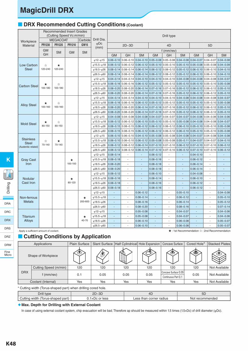
DRX Recommended Cutting Conditions (Coolant)
Cutting Conditions by ApplicationApplications Plain Surface Slant Surface Half Cylindrical Hole Expansion Concave Surface Cored Hole* Stacked Plates
Shape of Workpiece
DRXCutting Speed (m/min) 120 120 120 120 120 120 Not Available
f (mm/rev) 0.1 0.05 0.05 0.05Concave Surface 0.05
0.05 Not AvailableContinuous Part 0.1
Coolant (Internal) Yes Yes Yes Yes Yes Yes Not Available
Workpiece Material
Recommended Insert Grades (Cutting Speed Vc:m/min)
Drill Dia.φDc(mm)
Drill typeMEGACOAT Carbide
PR1230 PR1225 PR1210 GW15 2D~3D 4D 5D
GMGH
SM GM SM f (mm/rev)GM GH SM GM GH SM GM GH SM
Low Carbon Steel
☆120-240
★120-240
φ12~φ15 0.06~0.10 0.06~0.10 0.04~0.10 0.05~0.08 0.05~0.08 0.04~0.08 0.04~0.07 0.04~0.07 0.04~0.08
φ15.5~φ18 0.06~0.12 0.06~0.12 0.06~0.12 0.05~0.10 0.05~0.10 0.05~0.10 0.05~0.08 0.05~0.08 0.04~0.09
φ18.5~φ26 0.08~0.14 0.08~0.14 0.06~0.14 0.06~0.12 0.08~0.12 0.05~0.12 0.06~0.10 0.06~0.10 0.04~0.10
φ26.5~φ60 0.08~0.14 0.08~0.14 0.06~0.14 0.06~0.12 0.08~0.12 0.05~0.12 0.06~0.10 0.06~0.10 0.04~0.10
Carbon Steel★
100-180
☆100-180
φ12~φ15 0.04~0.14 0.04~0.14 0.04~0.10 0.04~0.10 0.04~0.10 0.04~0.08 0.04~0.08 0.04~0.08 0.04~0.07
φ15.5~φ18 0.06~0.16 0.06~0.16 0.06~0.12 0.05~0.12 0.05~0.12 0.05~0.10 0.05~0.10 0.05~0.10 0.05~0.08
φ18.5~φ26 0.08~0.20 0.08~0.20 0.06~0.14 0.07~0.16 0.07~0.16 0.05~0.12 0.06~0.12 0.06~0.12 0.05~0.10
φ26.5~φ60 0.08~0.20 0.08~0.20 0.06~0.14 0.07~0.16 0.07~0.16 0.05~0.12 0.06~0.12 0.06~0.12 0.05~0.10
Alloy Steel★
100-160
☆100-160
φ12~φ15 0.04~0.14 0.04~0.14 0.04~0.10 0.04~0.10 0.04~0.10 0.04~0.08 0.04~0.08 0.04~0.08 0.04~0.07
φ15.5~φ18 0.06~0.16 0.06~0.16 0.06~0.12 0.05~0.12 0.05~0.12 0.05~0.10 0.05~0.10 0.05~0.10 0.05~0.08
φ18.5~φ26 0.08~0.20 0.08~0.20 0.06~0.14 0.07~0.16 0.07~0.16 0.05~0.12 0.06~0.12 0.06~0.12 0.05~0.10
φ26.5~φ60 0.08~0.20 0.08~0.20 0.06~0.14 0.07~0.16 0.07~0.16 0.05~0.12 0.06~0.12 0.06~0.12 0.05~0.10
Mold Steel★
80-150
☆80-150
φ12~φ15 0.04~0.08 0.04~0.08 0.04~0.08 0.04~0.07 0.04~0.07 0.04~0.07 0.04~0.06 0.04~0.06 0.04~0.06
φ15.5~φ18 0.06~0.12 0.06~0.12 0.06~0.10 0.05~0.10 0.05~0.10 0.05~0.08 0.04~0.08 0.04~0.08 0.04~0.07
φ18.5~φ26 0.08~0.15 0.08~0.15 0.06~0.12 0.06~0.12 0.06~0.12 0.06~0.10 0.05~0.10 0.05~0.10 0.05~0.08
φ26.5~φ60 0.08~0.15 0.08~0.15 0.06~0.12 0.06~0.12 0.06~0.12 0.06~0.10 0.05~0.10 0.05~0.10 0.05~0.08
Stainless Steel
(Austenitic related)
☆70-140
★70-140
φ12~φ15 0.06~0.10 0.06~0.10 0.04~0.10 0.05~0.08 0.05~0.08 0.04~0.08 0.04~0.07 0.04~0.08 0.04~0.08
φ15.5~φ18 0.06~0.10 0.06~0.10 0.06~0.12 0.05~0.08 0.05~0.08 0.05~0.11 0.04~0.07 0.04~0.07 0.04~0.10
φ18.5~φ26 0.08~0.12 0.08~0.12 0.06~0.14 0.07~0.10 0.07~0.10 0.06~0.12 0.07~0.10 0.07~0.10 0.06~0.12
φ26.5~φ60 0.08~0.12 0.08~0.12 0.06~0.14 0.07~0.10 0.07~0.10 0.06~0.12 0.07~0.10 0.07~0.10 0.06~0.12
Gray Cast Iron
★100-150
φ12~φ15 0.08~0.14 - - 0.06~0.12 - - 0.04~0.10 - -
φ15.5~φ18 0.08~0.18 - - 0.08~0.16 - - 0.06~0.12 - -
φ18.5~φ26 0.08~0.20 - - 0.08~0.18 - - 0.06~0.14 - -
φ26.5~φ60 0.08~0.20 - - 0.08~0.18 - - 0.06~0.14 - -
NodularCast Iron
★80-120
φ12~φ15 0.08~0.12 - - 0.06~0.10 - - 0.04~0.08 - -
φ15.5~φ18 0.08~0.16 - - 0.08~0.14 - - 0.06~0.10 - -
φ18.5~φ26 0.08~0.18 - - 0.08~0.16 - - 0.06~0.12 - -
φ26.5~φ60 0.08~0.18 - - 0.08~0.16 - - 0.06~0.12 - -
Non-ferrousMetals
★200-600
φ12~φ15 - - 0.06~0.12 - - 0.05~0.10 - - 0.04~0.08
φ15.5~φ18 - - 0.08~0.14 - - 0.06~0.12 - - 0.05~0.10
φ18.5~φ26 - - 0.08~0.16 - - 0.06~0.14 - - 0.05~0.12
φ26.5~φ60 - - 0.08~0.20 - - 0.08~0.16 - - 0.07~0.14
Titanium Alloys
★40-70
φ12~φ15 - - 0.05~0.08 - - 0.04~0.07 - - 0.04~0.06
φ15.5~φ18 - - 0.05~0.08 - - 0.04~0.07 - - 0.04~0.06
φ18.5~φ26 - - 0.06~0.10 - - 0.06~0.08 - - 0.05~0.07
φ26.5~φ60 - - 0.06~0.10 - - 0.06~0.08 - - 0.05~0.07
· Apply a sufficient amount of coolant. ★ : 1st Recommendation ☆ : 2nd Recommendation
Max. Depth for Drilling with External Coolant
In case of using external coolant system, chip evacuation will be bad. Therefore ap should be measured within 1.5 times (1.5×Dc) of drill diameter (φDc).
Drill type 2D~3D 4D 5DCutting width (Torus-shaped part) 0.1×Dc or less Less than corner radius Not recommended
* Cutting width (Torus-shaped part) when drilling cored hole.
MagicDrill DRX
DRA
DRC
DRX
DRS
DRZ
DRW
FineMicro
K-edited.indd 48 25.08.2016 15:40:01
K48 K49
K
Dril
ling
Dril
ling
K
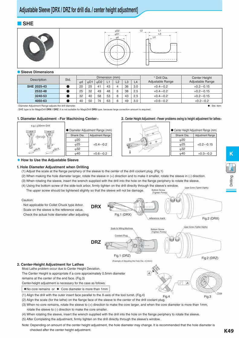
1. Hole Diameter Adjustment when Drilling(1) Adjust the scale at the flange periphery of the sleeve to the center of the drill coolant plug. (Fig.1)
(2) When making the hole diameter larger, rotate the sleeve in (+) direction and to make it smaller, rotate the sleeve in (-) direction.
(3) When rotating the sleeve, insert the wrench supplied with the drill into the hole on the flange periphery to rotate the sleeve.
(4) Using the bottom screw of the side-lock arbor, firmly tighten on the drill directly through the sleeve's window.
The upper screw should be tightened slightly so that the sleeve will not be damage.
Caution:
· Not applicable for Collet Chuck type Arbor.
· Scale on the sleeve is the reference value.
Check the actual hole diameter after adjusting.
Adjustable Sleeve [DRX / DRZ for drill dia. / center height adjustment]
SHE
Description Std.Dimension (mm) * Drill Dia.
Adjustable RangeCenter Height
Adjustable Rangeφd φD1 φD2 L1 L2 L3 L4SHE 2025-43 ● 20 25 41 43 4 36 3.0 +0.4~-0.2 +0.2~-0.15
2532-48 ● 25 32 49 48 6 38 2.5 +0.4~-0.2 +0.2~-0.15
3240-53 ● 32 40 58 53 6 43 2.5 +0.4~-0.2 +0.2~-0.15
4050-63 ● 40 50 74 63 6 49 3.0 +0.6~-0.2 +0.2~-0.2
· Diameter Adjustment Range adjusts the drill diameter. : Std. Item
· SHE type is for MagicDrill DRX / DRZ. It is not suitable for MagicDrill DRS type, because large correction amount is required.
Sleeve Dimensions
1. Diameter Adjustment ~For Machining Center~ 2. Center Height Adjustment ~Fewer problems owing to height adjustment for lathes~
Shank Dia. Adjustment Range
φ20
+0.4~-0.2φ25φ32φ40 +0.6~-0.2
Shank Dia. Adjustment Range
φ20
+0.2~-0.15φ25φ32φ40 +0.3~-0.2
How to Use the Adjustable Sleeve
Diameter Adjustment Range (mm) Center Height Adjustment Range (mm)
Fig.1 (DRX)
+0.6
+0.4
+0.2
Coolant Plug
Scale for Milling Machines Bottom Screw (Tighten Firmly)
Upper Screw (Tighten Slightly)
Fig.2 (DRZ)
DRX
DRZ
Fig.1 (DRZ)
Fig.2 (DRX)
Small Large
φ29.8 φ30.4
-0.2 +0.4
e.g.) φ30mm Drill
(Example of Adjusting the Hole Dia. +0.4mm)
reference mark
Bottom Screw (Tighten Firmly)
Upper Screw (Tighten Slightly)
+0.6
+0.4
+0.2
φD2φD1φd
L2 L1L3
L4
Fig.4 Fig.3
X-axis
of the
Machine
Core
2. Center-Height Adjustment for LathesMost Lathe problem occur due to Center Height Deviation.
The Center Height is appropriate if a core approximately 0.5mm diameter
remains at the center of the end face. (Fig.3)
Center-height adjustment is necessary for the case as follows:
No core remains or Core diameter is more than 1mm
(1) Align the drill with the outer insert face parallel to the X-axis of the tool turret. (Fig.4)
(2) Align the scale (for the lathe) on the flange face of the sleeve to the center of the drill coolant plug.
(3) When no core remains, rotate the sleeve to (+) direction to make the core larger, and when the core diameter is more than 1mm,
rotate the sleeve to (-) direction to make the core smaller.
(4) When rotating the sleeve, insert the wrench supplied with the drill into the hole on the flange periphery to rotate the sleeve.
(5) After Completing the adjustment, firmly tighten on the drill directly through the sleeve's window.
Note: Depending on amount of the center height adjustment, the hole diameter may change. It is recommended that the hole diameter is
checked after the center height adjustment.
K-edited.indd 49 25.08.2016 15:40:02
K50 K51
K
Dril
ling
Dril
ling
K
MagicDrill DRX / DRZ
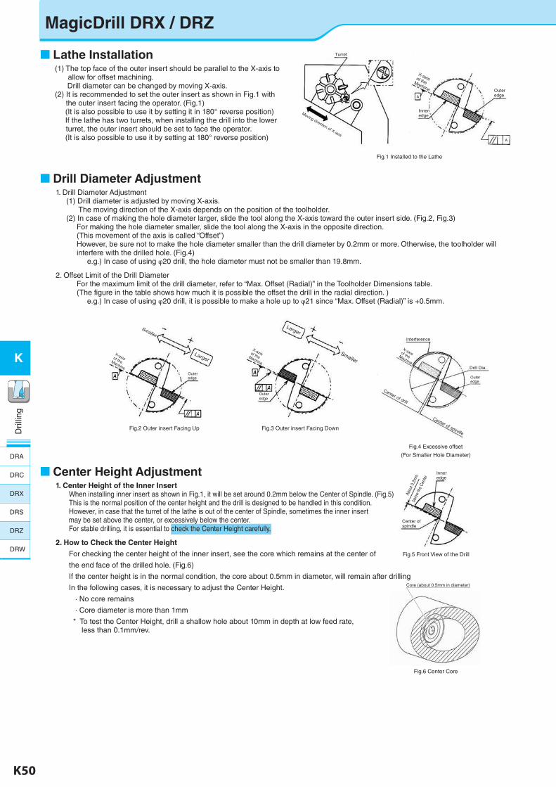
Lathe Installation(1) The top face of the outer insert should be parallel to the X-axis to
allow for offset machining. Drill diameter can be changed by moving X-axis.(2) It is recommended to set the outer insert as shown in Fig.1 with
the outer insert facing the operator. (Fig.1) (It is also possible to use it by setting it in 180° reverse position) If the lathe has two turrets, when installing the drill into the lower
turret, the outer insert should be set to face the operator. (It is also possible to use it by setting at 180° reverse position)
Drill Diameter Adjustment1. Drill Diameter Adjustment
(1) Drill diameter is adjusted by moving X-axis. The moving direction of the X-axis depends on the position of the toolholder.(2) In case of making the hole diameter larger, slide the tool along the X-axis toward the outer insert side. (Fig.2, Fig.3) For making the hole diameter smaller, slide the tool along the X-axis in the opposite direction. (This movement of the axis is called “Offset”) However, be sure not to make the hole diameter smaller than the drill diameter by 0.2mm or more. Otherwise, the toolholder will interfere with the drilled hole. (Fig.4) e.g.) In case of using φ20 drill, the hole diameter must not be smaller than 19.8mm.
2. Offset Limit of the Drill Diameter For the maximum limit of the drill diameter, refer to “Max. Offset (Radial)” in the Toolholder Dimensions table. (The figure in the table shows how much it is possible the offset the drill in the radial direction. ) e.g.) In case of using φ20 drill, it is possible to make a hole up to φ21 since “Max. Offset (Radial)” is +0.5mm.
Center Height Adjustment1. Center Height of the Inner Insert
When installing inner insert as shown in Fig.1, it will be set around 0.2mm below the Center of Spindle. (Fig.5)This is the normal position of the center height and the drill is designed to be handled in this condition.However, in case that the turret of the lathe is out of the center of Spindle, sometimes the inner insert
may be set above the center, or excessively below the center.For stable drilling, it is essential to check the Center Height carefully.
2. How to Check the Center Height
For checking the center height of the inner insert, see the core which remains at the center of
the end face of the drilled hole. (Fig.6)
If the center height is in the normal condition, the core about 0.5mm in diameter, will remain after drilling
In the following cases, it is necessary to adjust the Center Height.
· No core remains
· Core diameter is more than 1mm
* To test the Center Height, drill a shallow hole about 10mm in depth at low feed rate, less than 0.1mm/rev.
Fig.1 Installed to the Lathe
Fig.2 Outer insert Facing Up Fig.3 Outer insert Facing Down
Fig.4 Excessive offset
(For Smaller Hole Diameter)
(図1) 旋盤への取付け状態
Turret
Inner edge
Outer edge
A
A
Moving direction of X-axis
X-axis of the Machine
Outer edge
X-axis of the Machine
Larger
Smaller
(図2)外刃上面が上向きの状態
Outer edge
X-axis of the Machine
Larger
Smaller
(図3)外刃上面が下向きの状態
Outer edge
Interference
Drill Dia.
(図4)穴径が小さすぎる場合
Center of drill
Center of spindle
X-axis of the Machine
Fig.5 Front View of the Drill
Fig.6 Center Core(図6)中心部コア
Core (about 0.5mm in diameter)
(図5)ドリル正面図
Inner edge
Center of spindle
Abou
t 0.2
mm
be
low
the
Cent
er
DRA
DRC
DRX
DRS
DRZ
DRW
K-edited.indd 50 25.08.2016 15:40:04
K50 K51
K
Dril
ling
Dril
ling
K
Fig.7 Insert breakage near the center of the drill
Initial Installation(Inner insert positioned higher than normal)
Improved Position of Inner Insert(Inner insert positioned lower than normal)180° Rotation
Inneredge
Inner edge
Center of spindle
X-axisof the MachineCenter of spindle
Zooming near the center Zooming near the center
Center of drill
Center of drill
Inner edge
Inner edge
Inner edge
Inner edge
Outer edge
Center of spindle
X-axis of the Machine
Higher
below the center
90°
Center of drill
Inner edge
Zooming near the center
Inner Insert positioned too far below center
Center Height
Adjustment by
Moving the Tool
90° Rotation
Fig.8
Fig.9
Outer edge
Inner edge
Inner insert is positioned excessively below the center. 90° Rotation
Outer edge
Inner edge
X-axis of the Machine
X-axis of the Machine
90°
below the center
Higher
Center Height
Adjustment by
Moving the Tool
Fig.10
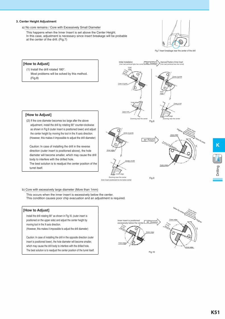
3. Center Height Adjustment
a) No core remains / Core with Excessively Small Diameter
This happens when the Inner Insert is set above the Center Height.In this case, adjustment is necessary since insert breakage will be probable at the center of the drill. (Fig.7)
b) Core with excessively large diameter (More than 1mm)
This occurs when the inner insert is excessively below the center.This condition causes poor chip evacuation and an adjustment is required.
[How to Adjust]
(1) Install the drill rotated 180°. Most problems will be solved by this method. (Fig.8)
[How to Adjust]
(2) If the core diameter becomes too large after the above adjustment, install the drill by rotating 90° counter-clockwise as shown in Fig.9 (outer insert is positioned lower) and adjust the center height by moving the tool in the X-axis direction.
(However, this makes it impossible to adjust the drill diameter)
Caution: In case of installing the drill in the reverse direction (outer insert is positioned above), the hole diameter will become smaller, which may cause the drill body to interfere with the drilled hole.The best solution is to readjust the center position of the turret itself.
[How to Adjust]
Install the drill rotating 90° as shown in Fig.10. (outer insert is positioned on the upper side) and adjust the center height by moving tool in the X-axis direction.(However, this makes it impossible to adjust the drill diameter)
Caution: In case of installing the drill in the opposite direction (outer insert is positioned lower), the hole diameter will become smaller, which may cause the drill body to interfere with the drilled hole.The best solution is to readjust the center position of the turret itself.
K-edited.indd 51 25.08.2016 15:40:04
K52 K53
K
Dril
ling
Dril
ling
K
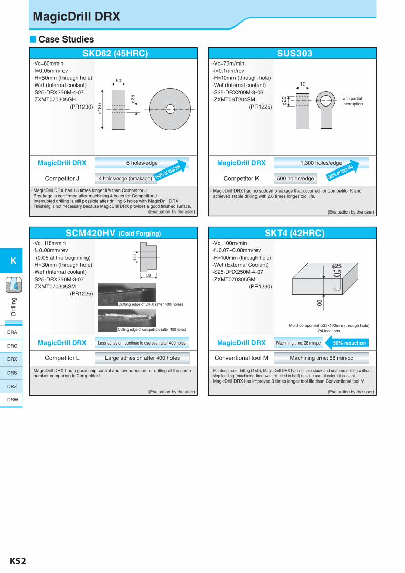
Case Studies
SKD62 (45HRC)·Vc=60m/min·f=0.05mm/rev·H=50mm (through hole)·Wet (Internal coolant)·S25-DRX250M-4-07·ZXMT070305GH
(PR1230)
MagicDrill DRX 6 holes/edge
Competitor J 4 holes/edge (breakage)
· MagicDrill DRX has 1.5 times longer life than Competitor J Breakage is confirmed after machining 4 holes for Competitor J Interrupted drilling is still possible after drilling 6 holes with MagicDrill DRX· Finishing is not necessary because MagicDrill DRX provides a good finished surface.
(Evaluation by the user)
SUS303·Vc=75m/min·f=0.1mm/rev·H=10mm (through hole)·Wet (Internal coolant)·S25-DRX200M-3-06·ZXMT06T204SM
(PR1225)
MagicDrill DRX 1,300 holes/edge
Competitor K 500 holes/edge
· MagicDrill DRX had no sudden breakage that occurred for Competitor K and achieved stable drilling with 2.6 times longer tool life.
(Evaluation by the user)
with partial interruption
150% of tool life
260% of tool life
10
φ20
φ25
φ180
50
SKT4 (42HRC)·Vc=100m/min·f=0.07~0.08mm/rev·H=100mm (through hole)·Wet (External Coolant)·S25-DRX250M-4-07·ZXMT070305GM
(PR1230)
MagicDrill DRX Machining time: 28 min/pc
Conventional tool M Machining time: 58 min/pc
· For deep hole drilling (4xD), MagicDrill DRX had no chip stuck and enabled drilling without step feeding (machining time was reduced in half) despite use of external coolant· MagicDrill DRX has improved 3 times longer tool life than Conventional tool M
(Evaluation by the user)
Mold component φ25x100mm (through hole) 24 locations
50% reduction
100
φ25
SCM420HV (Cold Forging)
·Vc=118m/min·f=0.08mm/rev(0.05 at the beginning)
·H=30mm (through hole)·Wet (Internal coolant)·S25-DRX250M-3-07·ZXMT070305SM
(PR1225)
MagicDrill DRX Less adhesion, continue to use even after 400 holes
Competitor L Large adhesion after 400 holes
· MagicDrill DRX had a good chip control and low adhesion for drilling of the same number comparing to Competitor L.
(Evaluation by the user)
Cutting edge of DRX (after 400 holes)
Cutting edge of competitors (after 400 holes)
φ25
30
MagicDrill DRX
DRA
DRC
DRX
DRS
DRZ
DRW
K-edited.indd 52 25.08.2016 15:40:06
K52 K53
K
Dril
ling
Dril
ling
K
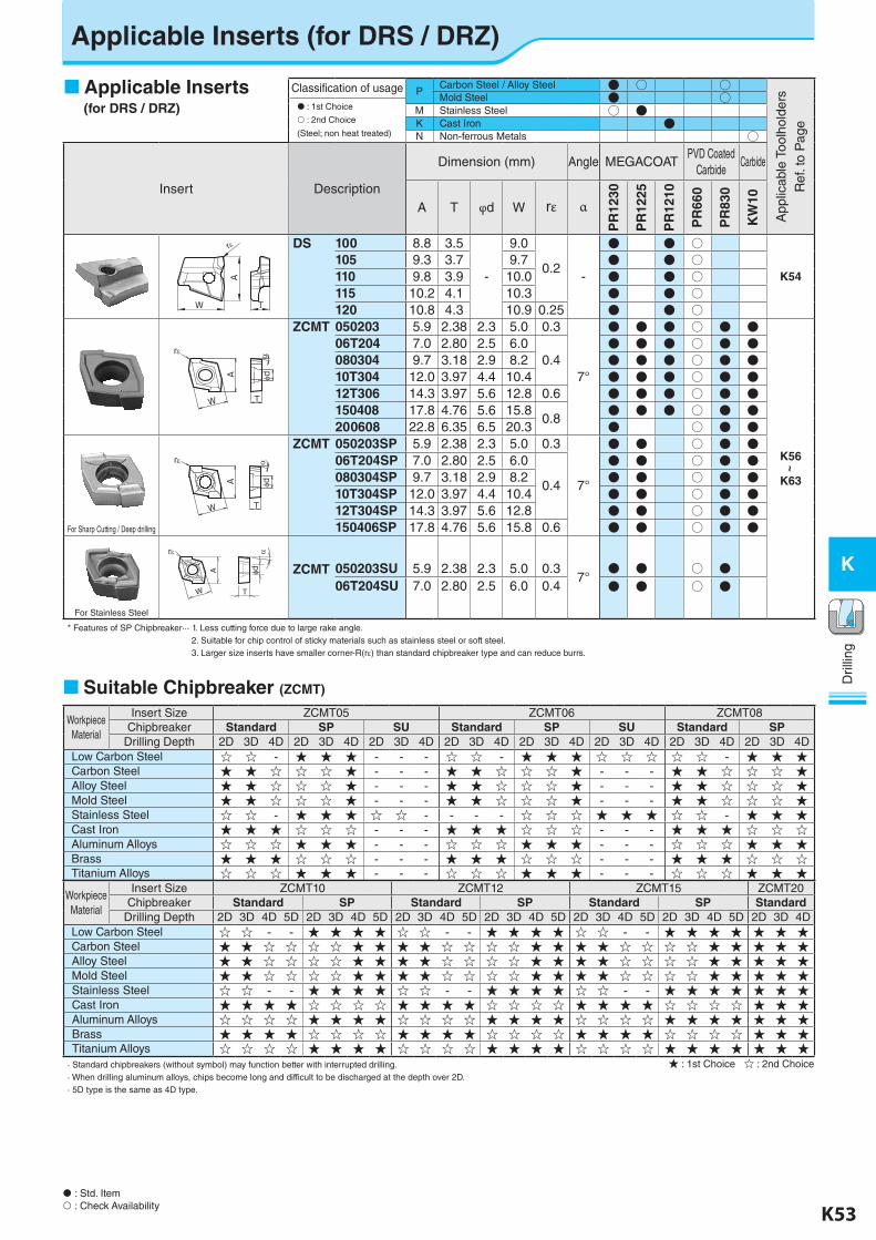
Applicable Inserts (for DRS / DRZ)
Classification of usage PCarbon Steel / Alloy Steel ● ○ ○
App
licab
le T
oolh
olde
rs
Ref
. to
Pag
e
Mold Steel ● ○ : 1st Choice
: 2nd Choice
(Steel; non heat treated)
M Stainless Steel ○ ●K Cast Iron ●N Non-ferrous Metals ○
Insert Description
Dimension (mm) Angle MEGACOATPVD Coated
CarbideCarbide
A T φd W rε α
PR
1230
PR
1225
PR
1210
PR
660
PR
830
KW
10
DS 100 8.8 3.5
-
9.0
0.2-
● ● ○
K54105 9.3 3.7 9.7 ● ● ○110 9.8 3.9 10.0 ● ● ○115 10.2 4.1 10.3 ● ● ○120 10.8 4.3 10.9 0.25 ● ● ○
ZCMT 050203 5.9 2.38 2.3 5.0 0.3
7°
● ● ● ○ ● ●
K56~
K63
06T204 7.0 2.80 2.5 6.00.4
● ● ● ○ ● ●080304 9.7 3.18 2.9 8.2 ● ● ● ○ ● ●10T304 12.0 3.97 4.4 10.4 ● ● ● ○ ● ●12T306 14.3 3.97 5.6 12.8 0.6 ● ● ● ○ ● ●150408 17.8 4.76 5.6 15.8
0.8● ● ● ○ ● ●
200608 22.8 6.35 6.5 20.3 ● ○ ● ●
For Sharp Cutting / Deep drilling
ZCMT 050203SP 5.9 2.38 2.3 5.0 0.3
7°
● ● ○ ● ●06T204SP 7.0 2.80 2.5 6.0
0.4
● ● ○ ● ●080304SP 9.7 3.18 2.9 8.2 ● ● ○ ● ●10T304SP 12.0 3.97 4.4 10.4 ● ● ○ ● ●12T304SP 14.3 3.97 5.6 12.8 ● ● ○ ● ●150406SP 17.8 4.76 5.6 15.8 0.6 ● ● ○ ● ●
For Stainless Steel
ZCMT 050203SU 5.9 2.38 2.3 5.0 0.37°
● ● ○ ●06T204SU 7.0 2.80 2.5 6.0 0.4 ● ● ○ ●
* Features of SP Chipbreaker··· 1. Less cutting force due to large rake angle. 2. Suitable for chip control of sticky materials such as stainless steel or soft steel. 3. Larger size inserts have smaller corner-R(rε) than standard chipbreaker type and can reduce burrs.
Applicable Inserts (for DRS / DRZ)
: Std. Item : Check Availability
Workpiece Material
Insert Size ZCMT05 ZCMT06 ZCMT08Chipbreaker Standard SP SU Standard SP SU Standard SP
Drilling Depth 2D 3D 4D 2D 3D 4D 2D 3D 4D 2D 3D 4D 2D 3D 4D 2D 3D 4D 2D 3D 4D 2D 3D 4DLow Carbon Steel ☆ ☆ - ★ ★ ★ - - - ☆ ☆ - ★ ★ ★ ☆ ☆ ☆ ☆ ☆ - ★ ★ ★Carbon Steel ★ ★ ☆ ☆ ☆ ★ - - - ★ ★ ☆ ☆ ☆ ★ - - - ★ ★ ☆ ☆ ☆ ★Alloy Steel ★ ★ ☆ ☆ ☆ ★ - - - ★ ★ ☆ ☆ ☆ ★ - - - ★ ★ ☆ ☆ ☆ ★Mold Steel ★ ★ ☆ ☆ ☆ ★ - - - ★ ★ ☆ ☆ ☆ ★ - - - ★ ★ ☆ ☆ ☆ ★Stainless Steel ☆ ☆ - ★ ★ ★ ☆ ☆ - - - - ☆ ☆ ☆ ★ ★ ★ ☆ ☆ - ★ ★ ★Cast Iron ★ ★ ★ ☆ ☆ ☆ - - - ★ ★ ★ ☆ ☆ ☆ - - - ★ ★ ★ ☆ ☆ ☆Aluminum Alloys ☆ ☆ ☆ ★ ★ ★ - - - ☆ ☆ ☆ ★ ★ ★ - - - ☆ ☆ ☆ ★ ★ ★Brass ★ ★ ★ ☆ ☆ ☆ - - - ★ ★ ★ ☆ ☆ ☆ - - - ★ ★ ★ ☆ ☆ ☆Titanium Alloys ☆ ☆ ☆ ★ ★ ★ - - - ☆ ☆ ☆ ★ ★ ★ - - - ☆ ☆ ☆ ★ ★ ★
Workpiece Material
Insert Size ZCMT10 ZCMT12 ZCMT15 ZCMT20Chipbreaker Standard SP Standard SP Standard SP Standard
Drilling Depth 2D 3D 4D 5D 2D 3D 4D 5D 2D 3D 4D 5D 2D 3D 4D 5D 2D 3D 4D 5D 2D 3D 4D 5D 2D 3D 4DLow Carbon Steel ☆ ☆ - - ★ ★ ★ ★ ☆ ☆ - - ★ ★ ★ ★ ☆ ☆ - - ★ ★ ★ ★ ★ ★ ★Carbon Steel ★ ★ ☆ ☆ ☆ ☆ ★ ★ ★ ★ ☆ ☆ ☆ ☆ ★ ★ ★ ★ ☆ ☆ ☆ ☆ ★ ★ ★ ★ ★Alloy Steel ★ ★ ☆ ☆ ☆ ☆ ★ ★ ★ ★ ☆ ☆ ☆ ☆ ★ ★ ★ ★ ☆ ☆ ☆ ☆ ★ ★ ★ ★ ★Mold Steel ★ ★ ☆ ☆ ☆ ☆ ★ ★ ★ ★ ☆ ☆ ☆ ☆ ★ ★ ★ ★ ☆ ☆ ☆ ☆ ★ ★ ★ ★ ★Stainless Steel ☆ ☆ - - ★ ★ ★ ★ ☆ ☆ - - ★ ★ ★ ★ ☆ ☆ - - ★ ★ ★ ★ ★ ★ ★Cast Iron ★ ★ ★ ★ ☆ ☆ ☆ ☆ ★ ★ ★ ★ ☆ ☆ ☆ ☆ ★ ★ ★ ★ ☆ ☆ ☆ ☆ ★ ★ ★Aluminum Alloys ☆ ☆ ☆ ☆ ★ ★ ★ ★ ☆ ☆ ☆ ☆ ★ ★ ★ ★ ☆ ☆ ☆ ☆ ★ ★ ★ ★ ★ ★ ★Brass ★ ★ ★ ★ ☆ ☆ ☆ ☆ ★ ★ ★ ★ ☆ ☆ ☆ ☆ ★ ★ ★ ★ ☆ ☆ ☆ ☆ ★ ★ ★Titanium Alloys ☆ ☆ ☆ ☆ ★ ★ ★ ★ ☆ ☆ ☆ ☆ ★ ★ ★ ★ ☆ ☆ ☆ ☆ ★ ★ ★ ★ ★ ★ ★
· Standard chipbreakers (without symbol) may function better with interrupted drilling.· When drilling aluminum alloys, chips become long and difficult to be discharged at the depth over 2D.· 5D type is the same as 4D type.
r
W
A
T
A
W
r
T
d
A
W T
r
d
A
W T
r
d
★ : 1st Choice ☆ : 2nd Choice
Suitable Chipbreaker (ZCMT)
K-edited.indd 53 25.08.2016 15:40:08
K54 K55
K
Dril
ling
Dril
ling
K
MagicDrill Mini3.5×D Type
: Std. Item
L1
L2
L3
D d
9 D
rill E
nd
d1
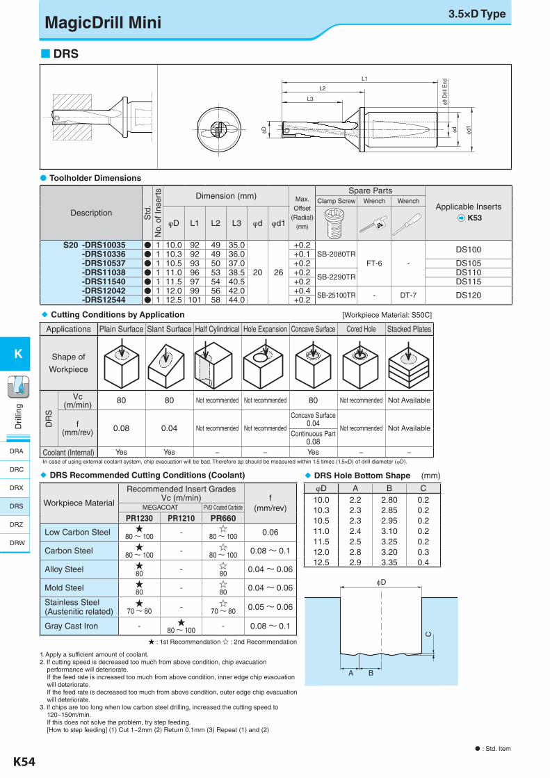
DRS
Description Std
.N
o. o
f Ins
erts Dimension (mm) Max.
Offset (Radial)
(mm)
Spare Parts
Applicable InsertsK53
Clamp Screw Wrench Wrench
φD L1 L2 L3 φd φd1
S20 -DRS10035 ● 1 10.0 92 49 35.0
20 26
+0.2SB-2080TR
FT-6 -
DS100-DRS10336 ● 1 10.3 92 49 36.0 +0.1-DRS10537 ● 1 10.5 93 50 37.0 +0.2 DS105-DRS11038 ● 1 11.0 96 53 38.5 +0.2
SB-2290TRDS110
-DRS11540 ● 1 11.5 97 54 40.5 +0.2 DS115-DRS12042 ● 1 12.0 99 56 42.0 +0.4 SB-25100TR - DT-7 DS120-DRS12544 ● 1 12.5 101 58 44.0 +0.2
1. Apply a sufficient amount of coolant.2. If cutting speed is decreased too much from above condition, chip evacuation performance will deteriorate. If the feed rate is increased too much from above condition, inner edge chip evacuation will deteriorate. If the feed rate is decreased too much from above condition, outer edge chip evacuation will deteriorate.3. If chips are too long when low carbon steel drilling, increased the cutting speed to 120~150m/min. If this does not solve the problem, try step feeding. [How to step feeding] (1) Cut 1~2mm (2) Return 0.1mm (3) Repeat (1) and (2)
C
BA
D
Toolholder Dimensions
Cutting Conditions by Application [Workpiece Material: S50C]
Applications Plain Surface Slant Surface Half Cylindrical Hole Expansion Concave Surface Cored Hole Stacked Plates
Shape of
Workpiece
DR
S
Vc(m/min) 80 80 Not recommended Not recommended 80 Not recommended Not Available
f(mm/rev) 0.08 0.04 Not recommended Not recommended
Concave Surface0.04
Not recommended Not AvailableContinuous Part
0.08Coolant (Internal) Yes Yes − − Yes − −
·In case of using external coolant system, chip evacuation will be bad. Therefore ap should be measured within 1.5 times (1.5×D) of drill diameter (φD).
DRS Hole Bottom Shape (mm)
φD A B C10.0 2.2 2.80 0.210.3 2.3 2.85 0.210.5 2.3 2.95 0.211.0 2.4 3.10 0.211.5 2.5 3.25 0.212.0 2.8 3.20 0.312.5 2.9 3.35 0.4
DRS Recommended Cutting Conditions (Coolant)
Workpiece Material
Recommended Insert GradesVc (m/min) f
(mm/rev)MEGACOAT PVD Coated Carbide
PR1230 PR1210 PR660
Low Carbon Steel ★80 〜 100 - ☆
80 〜 100 0.06
Carbon Steel ★80 〜 100 - ☆
80 〜 100 0.08 〜 0.1
Alloy Steel ★80 - ☆
80 0.04 〜 0.06
Mold Steel ★80 - ☆
80 0.04 〜 0.06
Stainless Steel(Austenitic related)
★70 〜 80 - ☆
70 〜 80 0.05 〜 0.06
Gray Cast Iron - ★80 〜 100 - 0.08 〜 0.1
★ : 1st Recommendation ☆ : 2nd Recommendation
DRA
DRC
DRX
DRS
DRZ
DRW
K-edited.indd 54 25.08.2016 15:40:10
K54 K55
K
Dril
ling
Dril
ling
K
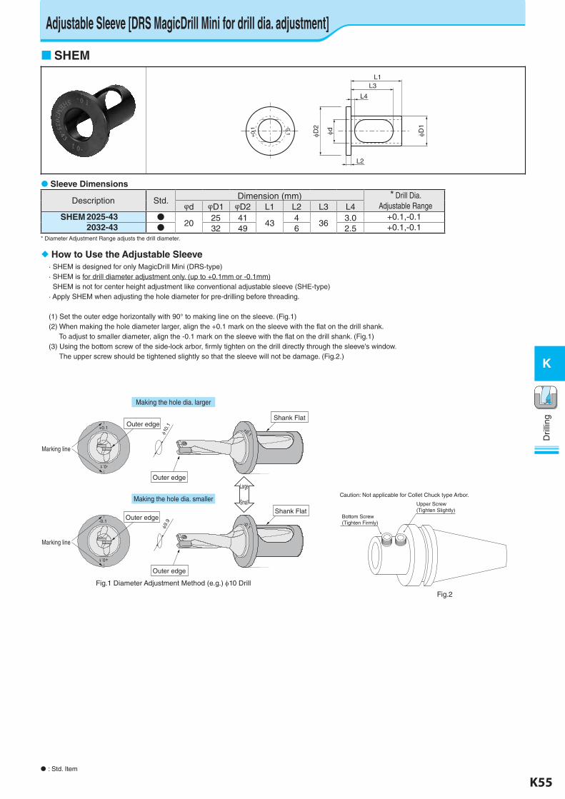
Adjustable Sleeve [DRS MagicDrill Mini for drill dia. adjustment]
: Std. Item
SHEM
+0.
1
-0.1 D2 d D1
L2
L4
L3L1
How to Use the Adjustable Sleeve· SHEM is designed for only MagicDrill Mini (DRS-type)· SHEM is for drill diameter adjustment only. (up to +0.1mm or -0.1mm) SHEM is not for center height adjustment like conventional adjustable sleeve (SHE-type)· Apply SHEM when adjusting the hole diameter for pre-drilling before threading.
(1) Set the outer edge horizontally with 90° to making line on the sleeve. (Fig.1)(2) When making the hole diameter larger, align the +0.1 mark on the sleeve with the flat on the drill shank. To adjust to smaller diameter, align the -0.1 mark on the sleeve with the flat on the drill shank. (Fig.1)(3) Using the bottom screw of the side-lock arbor, firmly tighten on the drill directly through the sleeve's window. The upper screw should be tightened slightly so that the sleeve will not be damage. (Fig.2.)
Caution: Not applicable for Collet Chuck type Arbor.
+0.1
-0.1
+0.1
Making the hole dia. larger
Making the hole dia. smaller
Fig.1 Diameter Adjustment Method (e.g.) 10 Drill
Outer edge
Shank Flat
10.1Outer edge
Marking line
-0.1
+0.1
-0.1
Outer edge
Shank Flat
9.9Outer edge
Marking line
Large
Small
Fig.2
Bottom Screw(Tighten Firmly)
Upper Screw(Tighten Slightly)
Sleeve Dimensions
Description Std. Dimension (mm) * Drill Dia. Adjustable Rangeφd φD1 φD2 L1 L2 L3 L4
SHEM 2025-43 ●20
25 4143
436
3.0 +0.1,-0.12032-43 ● 32 49 6 2.5 +0.1,-0.1
* Diameter Adjustment Range adjusts the drill diameter.
K-edited.indd 55 25.08.2016 15:40:11
K56 K57
K
Dril
ling
Dril
ling
K
: Std. Item
2D2D2D
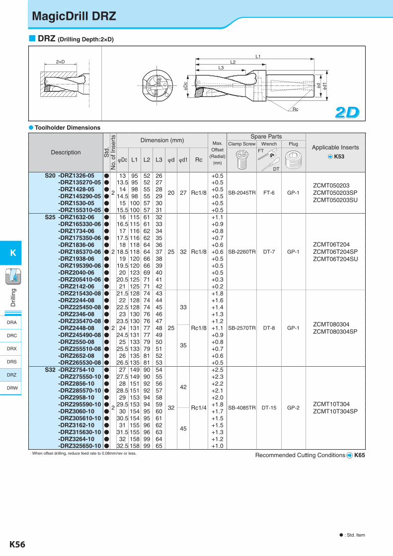
DRZ (Drilling Depth:2×D)
2×DL1
L3L2
Dc
Rc
d d1
Toolholder Dimensions
Description Std
.N
o. o
f Ins
erts Dimension (mm) Max.
Offset (Radial)
(mm)
Spare Parts
Applicable Inserts
K53
Clamp Screw Wrench Plug
φDc L1 L2 L3 φd φd1 Rc
S20 -DRZ1326-05 ●
2
13 95 52 26
20 27 Rc1/8
+0.5
SB-2045TR FT-6 GP-1ZCMT050203ZCMT050203SPZCMT050203SU
-DRZ135270-05 ● 13.5 95 52 27 +0.5-DRZ1428-05 ● 14 98 55 28 +0.5-DRZ145290-05 ● 14.5 98 55 29 +0.5-DRZ1530-05 ● 15 100 57 30 +0.5-DRZ155310-05 ● 15.5 100 57 31 +0.5
S25 -DRZ1632-06 ●
2
16 115 61 32
25 32 Rc1/8
+1.1
SB-2260TR DT-7 GP-1ZCMT06T204ZCMT06T204SPZCMT06T204SU
-DRZ165330-06 ● 16.5 115 61 33 +0.9-DRZ1734-06 ● 17 116 62 34 +0.8-DRZ175350-06 ● 17.5 116 62 35 +0.7-DRZ1836-06 ● 18 118 64 36 +0.6-DRZ185370-06 ● 18.5 118 64 37 +0.6-DRZ1938-06 ● 19 120 66 38 +0.5-DRZ195390-06 ● 19.5 120 66 39 +0.5-DRZ2040-06 ● 20 123 69 40 +0.5-DRZ205410-06 ● 20.5 125 71 41 +0.3-DRZ2142-06 ● 21 125 71 42 +0.2-DRZ215430-08 ●
2
21.5 128 74 43
25
33
Rc1/8
+1.8
SB-2570TR DT-8 GP-1ZCMT080304ZCMT080304SP
-DRZ2244-08 ● 22 128 74 44 +1.6-DRZ225450-08 ● 22.5 128 74 45 +1.4-DRZ2346-08 ● 23 130 76 46 +1.3-DRZ235470-08 ● 23.5 130 76 47 +1.2-DRZ2448-08 ● 24 131 77 48
35
+1.1-DRZ245490-08 ● 24.5 131 77 49 +0.9-DRZ2550-08 ● 25 133 79 50 +0.8-DRZ255510-08 ● 25.5 133 79 51 +0.7-DRZ2652-08 ● 26 135 81 52 +0.6-DRZ265530-08 ● 26.5 135 81 53 +0.5
S32 -DRZ2754-10 ●
2
27 149 90 54
32
42
Rc1/4
+2.5
SB-4085TR DT-15 GP-2ZCMT10T304ZCMT10T304SP
-DRZ275550-10 ● 27.5 149 90 55 +2.3-DRZ2856-10 ● 28 151 92 56 +2.2-DRZ285570-10 ● 28.5 151 92 57 +2.1-DRZ2958-10 ● 29 153 94 58 +2.0-DRZ295590-10 ● 29.5 153 94 59 +1.8-DRZ3060-10 ● 30 154 95 60
45
+1.7-DRZ305610-10 ● 30.5 154 95 61 +1.5-DRZ3162-10 ● 31 155 96 62 +1.5-DRZ315630-10 ● 31.5 155 96 63 +1.3-DRZ3264-10 ● 32 158 99 64 +1.2-DRZ325650-10 ● 32.5 158 99 65 +1.0
· When offset drilling, reduce feed rate to 0.08mm/rev or less.
FT
DT
MagicDrill DRZ
Recommended Cutting Conditions K65
DRA
DRC
DRX
DRS
DRZ
DRW
K-edited.indd 56 25.08.2016 15:40:13
K56 K57
K
Dril
ling
Dril
ling
K
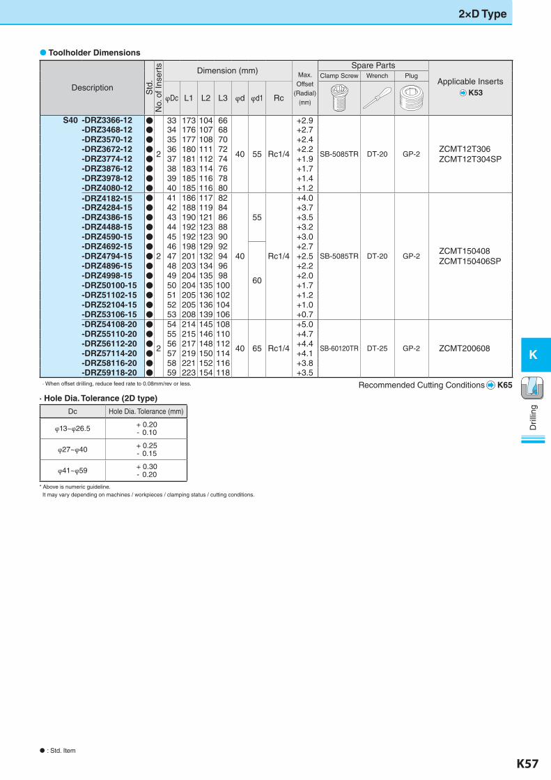
2×D Type
: Std. Item
Description Std
.N
o. o
f Ins
erts Dimension (mm) Max.
Offset (Radial)
(mm)
Spare Parts
Applicable InsertsK53
Clamp Screw Wrench Plug
φDc L1 L2 L3 φd φd1 Rc
S40 -DRZ3366-12 ●
2
33 173 104 66
40 55 Rc1/4
+2.9
SB-5085TR DT-20 GP-2ZCMT12T306ZCMT12T304SP
-DRZ3468-12 ● 34 176 107 68 +2.7-DRZ3570-12 ● 35 177 108 70 +2.4-DRZ3672-12 ● 36 180 111 72 +2.2-DRZ3774-12 ● 37 181 112 74 +1.9-DRZ3876-12 ● 38 183 114 76 +1.7-DRZ3978-12 ● 39 185 116 78 +1.4-DRZ4080-12 ● 40 185 116 80 +1.2-DRZ4182-15 ●
2
41 186 117 82
40
55
Rc1/4
+4.0
SB-5085TR DT-20 GP-2ZCMT150408ZCMT150406SP
-DRZ4284-15 ● 42 188 119 84 +3.7-DRZ4386-15 ● 43 190 121 86 +3.5-DRZ4488-15 ● 44 192 123 88 +3.2-DRZ4590-15 ● 45 192 123 90 +3.0-DRZ4692-15 ● 46 198 129 92
60
+2.7-DRZ4794-15 ● 47 201 132 94 +2.5-DRZ4896-15 ● 48 203 134 96 +2.2-DRZ4998-15 ● 49 204 135 98 +2.0-DRZ50100-15 ● 50 204 135 100 +1.7-DRZ51102-15 ● 51 205 136 102 +1.2-DRZ52104-15 ● 52 205 136 104 +1.0-DRZ53106-15 ● 53 208 139 106 +0.7-DRZ54108-20 ●
2
54 214 145 108
40 65 Rc1/4
+5.0
SB-60120TR DT-25 GP-2 ZCMT200608
-DRZ55110-20 ● 55 215 146 110 +4.7-DRZ56112-20 ● 56 217 148 112 +4.4-DRZ57114-20 ● 57 219 150 114 +4.1-DRZ58116-20 ● 58 221 152 116 +3.8-DRZ59118-20 ● 59 223 154 118 +3.5
· When offset drilling, reduce feed rate to 0.08mm/rev or less. Recommended Cutting Conditions K65
Toolholder Dimensions
· Hole Dia. Tolerance (2D type)
Dc Hole Dia. Tolerance (mm)
φ13~φ26.5 + 0.20- 0.10
φ27~φ40 + 0.25- 0.15
φ41~φ59 + 0.30- 0.20
* Above is numeric guideline. It may vary depending on machines / workpieces / clamping status / cutting conditions.
K-edited.indd 57 25.08.2016 15:40:13

K58 K59
K
Dril
ling
Dril
ling
K
: Std. Item
DRZ (Drilling Depth:3×D)
3D3D3D
3×D
L1
L3L2
Dc
Rc
d d1
Toolholder Dimensions
Description Std
.N
o. o
f Ins
erts Dimension (mm) Max.
Offset (Radial)
(mm)
Spare Parts
Applicable InsertsK53
Clamp Screw Wrench Plug
φDc L1 L2 L3 φd φd1 Rc
S20 -DRZ1339-05 ●
2
13 108 65 39
20 27 Rc1/8
+0.5
SB-2045TR FT-6 GP-1ZCMT050203ZCMT050203SPZCMT050203SU
-DRZ135405-05 ● 13.5 108 65 40.5 +0.5-DRZ1442-05 ● 14 112 69 42 +0.5-DRZ145435-05 ● 14.5 112 69 43.5 +0.5-DRZ1545-05 ● 15 115 72 45 +0.5-DRZ155465-05 ● 15.5 115 72 46.5 +0.5
S25 -DRZ1648-06 ●
2
16 131 77 48
25 32 Rc1/8
+1.1
SB-2260TR DT-7 GP-1ZCMT06T204ZCMT06T204SPZCMT06T204SU
-DRZ165495-06 ● 16.5 131 77 49.5 +0.9-DRZ1751-06 ● 17 133 79 51 +0.8-DRZ175525-06 ● 17.5 133 79 52.5 +0.7-DRZ1854-06 ● 18 136 82 54 +0.6-DRZ185555-06 ● 18.5 136 82 55.5 +0.6-DRZ1957-06 ● 19 139 85 57 +0.5-DRZ195585-06 ● 19.5 139 85 58.5 +0.5-DRZ2060-06 ● 20 143 89 60 +0.5-DRZ205615-06 ● 20.5 146 92 61.5 +0.3-DRZ2163-06 ● 21 146 92 63 +0.2-DRZ215645-08 ●
2
21.5 147 93 64.5
25
33
Rc1/8
+1.8
SB-2570TR DT-8 GP-1ZCMT080304ZCMT080304SP
-DRZ2266-08 ● 22 147 93 66 +1.6-DRZ225675-08 ● 22.5 147 93 67.5 +1.4-DRZ2369-08 ● 23 150 96 69 +1.3-DRZ235705-08 ● 23.5 150 96 70.5 +1.2-DRZ2472-08 ● 24 152 98 72
35
+1.1-DRZ245735-08 ● 24.5 152 98 73.5 +0.9-DRZ2575-08 ● 25 155 101 75 +0.8-DRZ255765-08 ● 25.5 155 101 76.5 +0.7-DRZ2678-08 ● 26 158 104 78 +0.6-DRZ265795-08 ● 26.5 158 104 79.5 +0.5
S32 -DRZ2781-10 ●
2
27 173 114 81
32
42
Rc1/4
+2.5
SB-4085TR DT-15 GP-2ZCMT10T304ZCMT10T304SP
-DRZ275825-10 ● 27.5 173 114 82.5 +2.3-DRZ2884-10 ● 28 176 117 84 +2.2-DRZ285855-10 ● 28.5 176 117 85.5 +2.1-DRZ2987-10 ● 29 179 120 87 +2.0-DRZ295885-10 ● 29.5 179 120 88.5 +1.8-DRZ3090-10 ● 30 181 122 90
45
+1.7-DRZ305915-10 ● 30.5 181 122 91.5 +1.5-DRZ3193-10 ● 31 183 124 93 +1.5-DRZ315945-10 ● 31.5 183 124 94.5 +1.3-DRZ3296-10 ● 32 187 128 96 +1.2-DRZ325975-10 ● 32.5 187 128 97.5 +1.0-DRZ3399-12 ●
2
33 193 134 99
32 55 Rc1/4
+2.9
SB-5085TR DT-20 GP-2ZCMT12T306ZCMT12T304SP
-DRZ34102-12 ● 34 197 138 102 +2.7-DRZ35105-12 ● 35 199 140 105 +2.4-DRZ36108-12 ● 36 203 144 108 +2.2-DRZ37111-12 ● 37 205 146 111 +1.9-DRZ38114-12 ● 38 208 149 114 +1.7-DRZ39117-12 ● 39 211 152 117 +1.4-DRZ40120-12 ● 40 212 153 120 +1.2
· When offset drilling, reduce feed rate to 0.08mm/rev or less. Recommended Cutting Conditions K65
FT
DT
MagicDrill DRZ
DRA
DRC
DRX
DRS
DRZ
DRW
K-edited.indd 58 25.08.2016 15:40:15
K58 K59
K
Dril
ling
Dril
ling
K
3×D Type
: Std. Item
Toolholder Dimensions
Description Std
.N
o. o
f Ins
erts Dimension (mm) Max.
Offset (Radial)
(mm)
Spare Parts
Applicable InsertsK53
Clamp Screw Wrench Plug
φDc L1 L2 L3 φd φd1 Rc
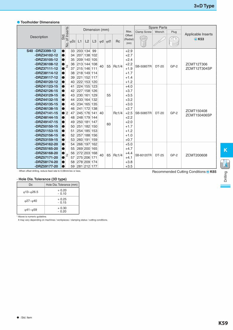
S40 -DRZ3399-12 ●
2
33 203 134 99
40 55 Rc1/4
+2.9
SB-5085TR DT-20 GP-2ZCMT12T306ZCMT12T304SP
-DRZ34102-12 ● 34 207 138 102 +2.7-DRZ35105-12 ● 35 209 140 105 +2.4-DRZ36108-12 ● 36 213 144 108 +2.2-DRZ37111-12 ● 37 215 146 111 +1.9-DRZ38114-12 ● 38 218 149 114 +1.7-DRZ39117-12 ● 39 221 152 117 +1.4-DRZ40120-12 ● 40 222 153 120 +1.2-DRZ41123-15 ●
2
41 224 155 123
40
55
Rc1/4
+4.0
SB-5085TR DT-20 GP-2ZCMT150408ZCMT150406SP
-DRZ42126-15 ● 42 227 158 126 +3.7-DRZ43129-15 ● 43 230 161 129 +3.5-DRZ44132-15 ● 44 233 164 132 +3.2-DRZ45135-15 ● 45 234 165 135 +3.0-DRZ46138-15 ● 46 241 172 138
60
+2.7-DRZ47141-15 ● 47 245 176 141 +2.5-DRZ48144-15 ● 48 248 179 144 +2.2-DRZ49147-15 ● 49 250 181 147 +2.0-DRZ50150-15 ● 50 251 182 150 +1.7-DRZ51153-15 ● 51 254 185 153 +1.2-DRZ52156-15 ● 52 257 188 156 +1.0-DRZ53159-15 ● 53 260 191 159 +0.7-DRZ54162-20 ●
2
54 266 197 162
40 65 Rc1/4
+5.0
SB-60120TR DT-25 GP-2 ZCMT200608
-DRZ55165-20 ● 55 269 200 165 +4.7-DRZ56168-20 ● 56 272 203 168 +4.4-DRZ57171-20 ● 57 275 206 171 +4.1-DRZ58174-20 ● 58 278 209 174 +3.8-DRZ59177-20 ● 59 281 212 177 +3.5
· When offset drilling, reduce feed rate to 0.08mm/rev or less. Recommended Cutting Conditions K65
· Hole Dia. Tolerance (3D type)
Dc Hole Dia. Tolerance (mm)
φ13~φ26.5 + 0.20- 0.10
φ27~φ40 + 0.25- 0.15
φ41~φ59 + 0.30- 0.20
* Above is numeric guideline. It may vary depending on machines / workpieces / clamping status / cutting conditions.
K-edited.indd 59 25.08.2016 15:40:16
K60 K61
K
Dril
ling
Dril
ling
K
: Std. Item
Toolholder Dimensions
Description Std
.N
o. o
f Ins
erts Dimension (mm) Max.
Offset (Radial)
(mm)
Spare Parts
Applicable InsertsK53
Clamp Screw Wrench Plug
φDc L1 L2 L3 φd φd1 Rc
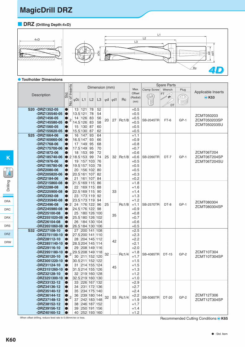
S20 -DRZ1352-05 ●
2
13 121 78 52
20 27 Rc1/8
+0.5
SB-2045TR FT-6 GP-1ZCMT050203ZCMT050203SPZCMT050203SU
-DRZ135540-05 ● 13.5 121 78 54 +0.5-DRZ1456-05 ● 14 126 83 56 +0.5-DRZ145580-05 ● 14.5 126 83 58 +0.5-DRZ1560-05 ● 15 130 87 60 +0.5-DRZ155620-05 ● 15.5 130 87 62 +0.5
S25 -DRZ1664-06 ●
2
16 147 93 64
25 32 Rc1/8
+1.1
SB-2260TR DT-7 GP-1ZCMT06T204ZCMT06T204SPZCMT06T204SU
-DRZ165660-06 ● 16.5 147 93 66 +0.9-DRZ1768-06 ● 17 149 95 68 +0.8-DRZ175700-06 ● 17.5 149 95 70 +0.7-DRZ1872-06 ● 18 153 99 72 +0.6-DRZ185740-06 ● 18.5 153 99 74 +0.6-DRZ1976-06 ● 19 157 103 76 +0.5-DRZ195780-06 ● 19.5 157 103 78 +0.5-DRZ2080-06 ● 20 156 102 80 +0.5-DRZ205820-06 ● 20.5 161 107 82 +0.3-DRZ2184-06 ● 21 161 107 84 +0.2-DRZ215860-08 ●
2
21.5 169 115 86
25
33
Rc1/8
+1.8
SB-2570TR DT-8 GP-1ZCMT080304ZCMT080304SP
-DRZ2288-08 ● 22 169 115 88 +1.6-DRZ225900-08 ● 22.5 169 115 90 +1.4-DRZ2392-08 ● 23 173 119 92 +1.3-DRZ235940-08 ● 23.5 173 119 94 +1.2-DRZ2496-08 ● 24 176 122 96
35
+1.1-DRZ245980-08 ● 24.5 176 122 98 +0.9-DRZ25100-08 ● 25 180 126 100 +0.8-DRZ2551020-08 ● 25.5 180 126 102 +0.7-DRZ26104-08 ● 26 184 130 104 +0.6-DRZ2651060-08 ● 26.5 184 130 106 +0.5
S32 -DRZ27108-10 ●
2
27 200 141 108
32
42
Rc1/4
+2.5
SB-4085TR DT-15 GP-2ZCMT10T304ZCMT10T304SP
-DRZ2751100-10 ● 27.5 200 141 110 +2.3-DRZ28112-10 ● 28 204 145 112 +2.2-DRZ2851140-10 ● 28.5 204 145 114 +2.1-DRZ29116-10 ● 29 208 149 116 +2.0-DRZ2951180-10 ● 29.5 208 149 118 +1.8-DRZ30120-10 ● 30 211 152 120
45
+1.7-DRZ3051220-10 ● 30.5 211 152 122 +1.5-DRZ31124-10 ● 31 214 155 124 +1.5-DRZ3151260-10 ● 31.5 214 155 126 +1.3-DRZ32128-10 ● 32 219 160 128 +1.2-DRZ3251300-10 ● 32.5 219 160 130 +1.0-DRZ33132-12 ●
2
33 226 167 132
32 55 Rc1/4
+2.9
SB-5085TR DT-20 GP-2ZCMT12T306ZCMT12T304SP
-DRZ34136-12 ● 34 231 172 136 +2.7-DRZ35140-12 ● 35 234 175 140 +2.4-DRZ36144-12 ● 36 239 180 144 +2.2-DRZ37148-12 ● 37 242 183 148 +1.9-DRZ38152-12 ● 38 246 187 152 +1.7-DRZ39156-12 ● 39 250 191 156 +1.4-DRZ40160-12 ● 40 252 193 160 +1.2
· When offset drilling, reduce feed rate to 0.06mm/rev or less. Recommended Cutting Conditions K65
DRZ (Drilling Depth:4×D)
4×D
L1
L3L2
Dc
Rc
d d1
4D4D4D
FT
DT
MagicDrill DRZ
DRA
DRC
DRX
DRS
DRZ
DRW
K-edited.indd 60 25.08.2016 15:40:17
K60 K61
K
Dril
ling
Dril
ling
K
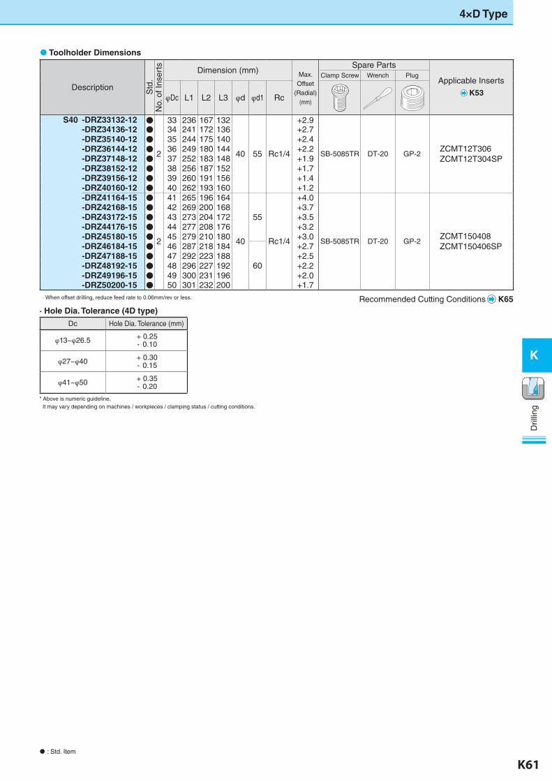
4×D Type
: Std. Item
Toolholder Dimensions
Description Std
.N
o. o
f Ins
erts Dimension (mm) Max.
Offset (Radial)
(mm)
Spare Parts
Applicable InsertsK53
Clamp Screw Wrench Plug
φDc L1 L2 L3 φd φd1 Rc
S40 -DRZ33132-12 ●
2
33 236 167 132
40 55 Rc1/4
+2.9
SB-5085TR DT-20 GP-2ZCMT12T306ZCMT12T304SP
-DRZ34136-12 ● 34 241 172 136 +2.7-DRZ35140-12 ● 35 244 175 140 +2.4-DRZ36144-12 ● 36 249 180 144 +2.2-DRZ37148-12 ● 37 252 183 148 +1.9-DRZ38152-12 ● 38 256 187 152 +1.7-DRZ39156-12 ● 39 260 191 156 +1.4-DRZ40160-12 ● 40 262 193 160 +1.2-DRZ41164-15 ●
2
41 265 196 164
40
55
Rc1/4
+4.0
SB-5085TR DT-20 GP-2ZCMT150408ZCMT150406SP
-DRZ42168-15 ● 42 269 200 168 +3.7-DRZ43172-15 ● 43 273 204 172 +3.5-DRZ44176-15 ● 44 277 208 176 +3.2-DRZ45180-15 ● 45 279 210 180 +3.0-DRZ46184-15 ● 46 287 218 184
60
+2.7-DRZ47188-15 ● 47 292 223 188 +2.5-DRZ48192-15 ● 48 296 227 192 +2.2-DRZ49196-15 ● 49 300 231 196 +2.0-DRZ50200-15 ● 50 301 232 200 +1.7
· When offset drilling, reduce feed rate to 0.06mm/rev or less. Recommended Cutting Conditions K65· Hole Dia. Tolerance (4D type)
Dc Hole Dia. Tolerance (mm)
φ13~φ26.5 + 0.25- 0.10
φ27~φ40 + 0.30- 0.15
φ41~φ50 + 0.35- 0.20
* Above is numeric guideline. It may vary depending on machines / workpieces / clamping status / cutting conditions.
K-edited.indd 61 25.08.2016 15:40:18
K62 K63
K
Dril
ling
Dril
ling
K
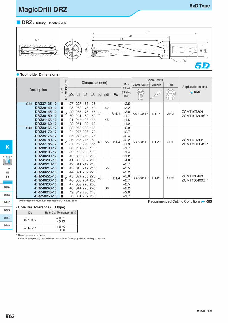
MagicDrill DRZ5×D Type
: Std. Item
DRZ (Drilling Depth:5×D)
5×D
L1
L3L2
Dc
Rc
d d1
Description Std
.N
o. o
f Ins
erts Dimension (mm) Max.
Offset (Radial)
(mm)
Spare Parts
Applicable Inserts
K53
Clamp Screw Wrench Plug
φDc L1 L2 L3 φd φd1 Rc
S32 -DRZ27135-10 ●
2
27 227 168 135
32
42
Rc1/4
+2.5
SB-4085TR DT-15 GP-2ZCMT10T304ZCMT10T304SP
-DRZ28140-10 ● 28 232 173 140 +2.2-DRZ29145-10 ● 29 237 178 145 +2.0-DRZ30150-10 ● 30 241 182 150
45+1.7
-DRZ31155-10 ● 31 245 186 155 +1.5-DRZ32160-10 ● 32 251 192 160 +1.2
S40 -DRZ33165-12 ●
2
33 269 200 165
40 55 Rc1/4
+2.9
SB-5085TR DT-20 GP-2ZCMT12T306ZCMT12T304SP
-DRZ34170-12 ● 34 275 206 170 +2.7-DRZ35175-12 ● 35 279 210 175 +2.4-DRZ36180-12 ● 36 285 216 180 +2.2-DRZ37185-12 ● 37 289 220 185 +1.9-DRZ38190-12 ● 38 294 225 190 +1.7-DRZ39195-12 ● 39 299 230 195 +1.4-DRZ40200-12 ● 40 302 233 200 +1.2-DRZ41205-15 ●
2
41 306 237 205
40
55
Rc1/4
+4.0
SB-5085TR DT-20 GP-2ZCMT150408ZCMT150406SP
-DRZ42210-15 ● 42 311 242 210 +3.7-DRZ43215-15 ● 43 316 247 215 +3.5-DRZ44220-15 ● 44 321 252 220 +3.2-DRZ45225-15 ● 45 324 255 225 +3.0-DRZ46230-15 ● 46 333 264 230
60
+2.7-DRZ47235-15 ● 47 339 270 235 +2.5-DRZ48240-15 ● 48 344 275 240 +2.2-DRZ49245-15 ● 49 349 280 245 +2.0-DRZ50250-15 ● 50 351 282 250 +1.7
· When offset drilling, reduce feed rate to 0.05mm/rev or less. Recommended Cutting Conditions K65
Toolholder Dimensions
· Hole Dia. Tolerance (5D type)
Dc Hole Dia. Tolerance (mm)
φ27~φ40 + 0.35- 0.15
φ41~φ50 + 0.40- 0.20
* Above is numeric guideline. It may vary depending on machines / workpieces / clamping status / cutting conditions.
DRA
DRC
DRX
DRS
DRZ
DRW
K-edited.indd 62 25.08.2016 15:40:20
K62 K63
K
Dril
ling
Dril
ling
K
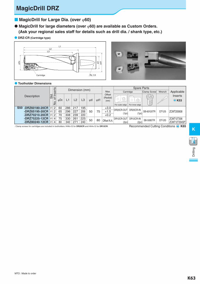
MagicDrill DRZ
MagicDrill for large diameters (over φ60) are available as Custom Orders. (Ask your regional sales staff for details such as drill dia. / shank type, etc.) DRZ-CR (Cartridge type)
L1
L3
Cartridge Rc 1/4
L2
φDc
φd φd1
Toolholder Dimensions
Description Std
.N
o. o
f Ins
erts Dimension (mm)
Max. Offset
(Radial)(mm)
Spare PartsApplicable
Inserts
K53
Cartridge Clamp Screw Wrench
φDc L1 L2 L3 φd φd1
For outer edge For inner edge
S50 -DRZ60180-20CR MTO 2 60 286 217 19550 75
+3.0DR20CR-OUT
(1pc)DR20CR-IN
(1pc)SB-60120TR DT-25 ZCMT200608-DRZ65195-20CR MTO 2 65 296 227 206 +1.5
-DRZ70210-20CR MTO 2 70 308 239 220 +0.2-DRZ75225-12CR MTO 4 75 330 261 225 50 80 Offset N.A.
DR12CR-OUT(2pc)
DR12CR-IN(2pc)
SB-5085TR DT-20 ZCMT12T306ZCMT12T304SP-DRZ80240-12CR MTO 4 80 340 271 240
· Clamp screws for cartridges are included in toolholders: HH6×12 for DR20CR and HH4×12 for DR12CR. Recommended Cutting Conditions K65
MagicDrill for Large Dia. (over φ60)
MTO : Made to order
K-edited.indd 63 25.08.2016 15:40:21
K64 K65
K
Dril
ling
Dril
ling
K
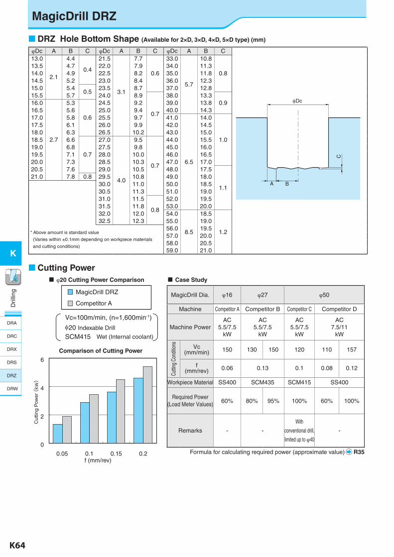
MagicDrill DRZ
φDc A B C φDc A B C φDc A B C13.0
2.1
4.4
0.4
21.5
3.1
7.7
0.6
33.0
5.7
10.8
0.813.5 4.7 22.0 7.9 34.0 11.314.0 4.9 22.5 8.2 35.0 11.814.5 5.2 23.0 8.4 36.0 12.315.0 5.4
0.523.5 8.7 37.0 12.8
15.5 5.7 24.0 8.9
0.7
38.0 13.30.916.0
2.7
5.3
0.6
24.5 9.2 39.0 13.816.5 5.6 25.0 9.4 40.0 14.317.0 5.8 25.5 9.7 41.0
6.5
14.0
1.0
17.5 6.1 26.0 9.9 42.0 14.518.0 6.3 26.5 10.2 43.0 15.018.5 6.6
0.7
27.0
4.0
9.5
0.7
44.0 15.519.0 6.8 27.5 9.8 45.0 16.019.5 7.1 28.0 10.0 46.0 16.520.0 7.3 28.5 10.3 47.0 17.020.5 7.6 29.0 10.5 48.0 17.5
1.1
21.0 7.8 0.8 29.5 10.8 49.0 18.030.0 11.0 50.0 18.530.5 11.3 51.0 19.031.0 11.5
0.8
52.0 19.531.5 11.8 53.0 20.032.0 12.0 54.0
8.5
18.5
1.2
32.5 12.3 55.0 19.0
* Above amount is standard value
(Varies within ±0.1mm depending on workpiece materials
and cutting conditions)
56.0 19.557.0 20.058.0 20.559.0 21.0
A B
C
Dc
Cut
ting
Pow
er
(kw
)
6
4
2
0
0.05 0.1 0.15 0.2f (mm/rev)
Comparison of Cutting Power
MagicDrill DRZ
Competitor A
Vc=100m/min, (n=1,600min-1)
20 Indexable Drill
SCM415 Wet (Internal coolant)
Cutting Power
DRZ Hole Bottom Shape (Available for 2×D, 3×D, 4×D, 5×D type) (mm)
φ20 Cutting Power Comparison Case Study
MagicDrill Dia. φ16 φ27 φ50
Machine Competitor A Competitor B Competitor C Competitor D
Machine PowerAC
5.5/7.5kW
AC5.5/7.5
kW
AC5.5/7.5
kW
AC7.5/11
kW
Cuttin
g Co
nditio
ns Vc(mm/min) 150 130 150 120 110 157
f(mm/rev) 0.06 0.13 0.1 0.08 0.12
Workpiece Material SS400 SCM435 SCM415 SS400
Required Power(Load Meter Values) 60% 80% 95% 100% 60% 100%
Remarks - -
With
conventional drill,
limited up to φ40
-
Formula for calculating required power (approximate value) R35
DRA
DRC
DRX
DRS
DRZ
DRW
K-edited.indd 64 25.08.2016 15:40:22
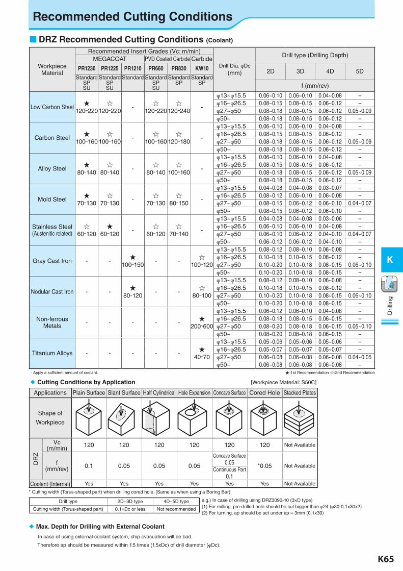
K64 K65
K
Dril
ling
Dril
ling
K
Recommended Cutting Conditions
DRZ Recommended Cutting Conditions (Coolant)
Workpiece Material
Recommended Insert Grades (Vc: m/min)
Drill Dia. φDc(mm)
Drill type (Drilling Depth)MEGACOAT PVD Coated Carbide Carbide
PR1230 PR1225 PR1210 PR660 PR830 KW10 2D 3D 4D 5DStandard
SPSU
StandardSPSU
Standard StandardSPSU
StandardSP
StandardSP f (mm/rev)
Low Carbon Steel★
120~220☆
120~220-
☆120~220
☆120~240
-
φ13~φ15.5 0.06~0.10 0.06~0.10 0.04~0.08 –φ16~φ26.5 0.08~0.15 0.08~0.15 0.06~0.12 –φ27~φ50 0.08~0.18 0.08~0.15 0.06~0.12 0.05~0.09φ50~ 0.08~0.18 0.08~0.15 0.06~0.12 –
Carbon Steel★
100~160☆
100~160-
☆100~160
☆120~180
-
φ13~φ15.5 0.06~0.10 0.06~0.10 0.04~0.08 –φ16~φ26.5 0.08~0.15 0.08~0.15 0.06~0.12 –φ27~φ50 0.08~0.18 0.08~0.15 0.06~0.12 0.05~0.09φ50~ 0.08~0.18 0.08~0.15 0.06~0.12 –
Alloy Steel★
80~140☆
80~140-
☆80~140
☆100~160
-
φ13~φ15.5 0.06~0.10 0.06~0.10 0.04~0.08 –φ16~φ26.5 0.08~0.15 0.08~0.15 0.06~0.12 –φ27~φ50 0.08~0.18 0.08~0.15 0.06~0.12 0.05~0.09φ50~ 0.08~0.18 0.08~0.15 0.06~0.12 –
Mold Steel★
70~130☆
70~130-
☆70~130
☆80~150
-
φ13~φ15.5 0.04~0.08 0.04~0.08 0.03~0.07 –φ16~φ26.5 0.08~0.12 0.06~0.10 0.06~0.08 –φ27~φ50 0.08~0.15 0.06~0.12 0.06~0.10 0.04~0.07φ50~ 0.08~0.15 0.06~0.12 0.06~0.10 –
Stainless Steel(Austenitic related)
☆60~120
★60~120
-☆
60~120☆
70~140-
φ13~φ15.5 0.04~0.08 0.04~0.08 0.03~0.06 –φ16~φ26.5 0.06~0.10 0.06~0.10 0.04~0.08 –φ27~φ50 0.06~0.10 0.06~0.12 0.04~0.10 0.04~0.07φ50~ 0.06~0.12 0.06~0.12 0.04~0.10 –
Gray Cast Iron - -★
100~150- -
☆100~120
φ13~φ15.5 0.08~0.12 0.08~0.10 0.06~0.08 –φ16~φ26.5 0.10~0.18 0.10~0.15 0.08~0.12 –φ27~φ50 0.10~0.20 0.10~0.18 0.08~0.15 0.06~0.10φ50~ 0.10~0.20 0.10~0.18 0.08~0.15 –
Nodular Cast Iron - -★
80~120- -
☆80~100
φ13~φ15.5 0.08~0.12 0.08~0.10 0.06~0.08 –φ16~φ26.5 0.10~0.18 0.10~0.15 0.08~0.12 –φ27~φ50 0.10~0.20 0.10~0.18 0.08~0.15 0.06~0.10φ50~ 0.10~0.20 0.10~0.18 0.08~0.15 –
Non-ferrous Metals - - - - -
★200~600
φ13~φ15.5 0.06~0.12 0.06~0.10 0.04~0.08 –φ16~φ26.5 0.08~0.18 0.08~0.15 0.06~0.15 –φ27~φ50 0.08~0.20 0.08~0.18 0.06~0.15 0.05~0.10φ50~ 0.08~0.20 0.08~0.18 0.06~0.15 –
Titanium Alloys - - - - -★
40~70
φ13~φ15.5 0.05~0.06 0.05~0.06 0.05~0.06 –φ16~φ26.5 0.05~0.07 0.05~0.07 0.05~0.07 –φ27~φ50 0.06~0.08 0.06~0.08 0.06~0.08 0.04~0.05φ50~ 0.06~0.08 0.06~0.08 0.06~0.08 –
· Apply a sufficient amount of coolant. ★:1st Recommendation ☆:2nd Recommendation
e.g.) In case of drilling using DRZ3090-10 (3×D type)(1) For milling, pre-drilled hole should be cut bigger than φ24 (φ30-0.1x30x2)(2) For turning, ap should be set under ap = 3mm (0.1x30)
Max. Depth for Drilling with External Coolant
In case of using external coolant system, chip evacuation will be bad.
Therefore ap should be measured within 1.5 times (1.5xDc) of drill diameter (φDc).
Cutting Conditions by Application [Workpiece Material: S50C]
Applications Plain Surface Slant Surface Half Cylindrical Hole Expansion Concave Surface Cored Hole Stacked Plates
Shape of
Workpiece
DR
Z
Vc(m/min) 120 120 120 120 120 120 Not Available
f(mm/rev) 0.1 0.05 0.05 0.05
Concave Surface0.05 *0.05 Not Available
Continuous Part0.1
Coolant (Internal) Yes Yes Yes Yes Yes Yes Not Available
* Cutting width (Torus-shaped part) when drilling cored hole. (Same as when using a Boring Bar).
Drill type 2D~3D type 4D~5D type
Cutting width (Torus-shaped part) 0.1×Dc or less Not recommended
K-edited.indd 65 25.08.2016 15:40:23
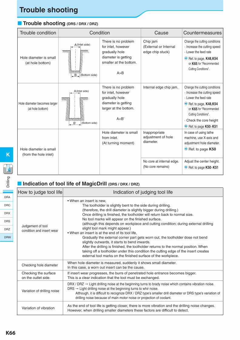
K66 K67
K
Dril
ling
Dril
ling
K
Indication of tool life of MagicDrill (DRS / DRX / DRZ)
How to judge tool life Indication of judging tool life
Judgement of tool condition and insert wear
• When an insert is new, The toolholder is slightly bent to the side during drilling.(therefore, the drill diameter is slightly bigger during drilling.)Once drilling is finished, the toolholder will return back to normal size.No tool marks will appear on the finished surface.(although this depends on workpiece and cutting condition: during external drilling slight tool mark might appear.)
• When an insert is at the end of its tool life, Gradually the external corner part gets worn out, the toolholder dose not bend slightly outwards, it starts to bend inwards.After the drilling is finished, the toolholder returns to the normal position. When taking off a toolholder under this condition the cutting edge of the insert creates external tool marks on the finished surface of the workpiece.
Checking hole diameterWhen hole diameter is measured, suddenly it shows small diameter. In this case, a worn out insert can be the cause.
Checking the surface on the outlet side
If insert wear progresses, the burrs of penetrated hole entrance becomes bigger.This is a clear indication that the tool must be exchanged.
Variation of drilling noise
DRX / DRZ " Light drilling noise at the beginning turns to brady noise which contains vibration noise.DRS " Light drilling noise at the beginning turns to whir noise.
Although, it is difficult to recognize DRX / DRZ type's smaller drill diameter or DRS type's variation ofdrilling noise because of main motor noise or projection of coolant.
Variation of vibrationAs the end of tool life is getting closer, there is more vibration and the drilling noise changes.However, when drilling smaller diameters these factors are difficult to detect.
Trouble shooting (DRS / DRX / DRZ)
Trouble condition Condition Cause Countermeasures
Hole diameter is small(at hole bottom)
There is no problem for inlet, however gradually hole diameter is getting smaller at the bottom.
A>B
Chip jam(External or Internal edge chip stuck)
Change the cutting conditions· Increase the cutting speed· Lower the feed rate
Ref. to page, K48,K54 or K65 for "Recommended
Cutting Conditions".
Hole diameter becomes larger(at hole bottom)
There is no problem for inlet, however gradually hole diameter is getting larger at the bottom.
A<B’
Internal edge chip jam. Change the cutting conditions· Increase the cutting speed· Lower the feed rate
Ref. to page, K48,K54 or K65 for "Recommended
Cutting Conditions".
· Check the core height
Ref. to page K50~K51
Hole diameter is small(from the hole inlet)
Hole diameter is small from inlet.(At turning moment)
Inappropriate adjustment of hole diameter.
In case of using lathe machine, use X-axis and adjustment hole diameter.
Ref. to page K50
No core at internal edge.(No core remains)
Adjust the center height.
Ref. to page K50~K51
A
B (Bottom side)
(Inlet side)
B' (Bottom side)
(Inlet side)A
Trouble shooting
DRA
DRC
DRX
DRS
DRZ
DRW
K-edited.indd 66 25.08.2016 15:40:24
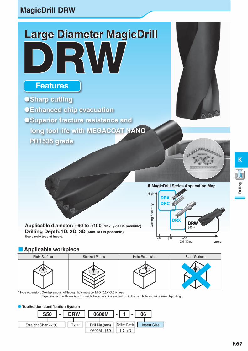
K66 K67
K
Dril
ling
Dril
ling
K
DRW
Applicable diameter: φ60 to φ100 (Max. φ200 is possible)
Drilling Depth:1D, 2D, 3D (Max. 5D is possible)Use single type of insert.
Features
Sharp cutting
Enhanced chip evacuation
Superior fracture resistance and
long tool life with MEGACOAT NANO
PR1535 grade
Large Diameter MagicDrill
DRADRC
DRX DRWφ60~
High
LargeDrill Dia.
Cut
ting
Acc
urac
y
φ8 φ12 φ60
MagicDrill Series Application Map
Applicable workpiecePlain Surface Stacked Plates Hole Expansion Slant Surface
* Hole expansion: Overlap amount of through hole must be 1/5D (0.2xφDc) or less. Expansion of blind holes is not possible because chips are built up in the next hole and will cause chip biting.
061- --0600MDRWS50
Drilling Depth Insert SizeDrill Dia.(mm)TypeStraight Shank 50
0600M : 60 1:1×D
Toolholder Identification System
MagicDrill DRW
K-edited.indd 67 25.08.2016 15:40:29
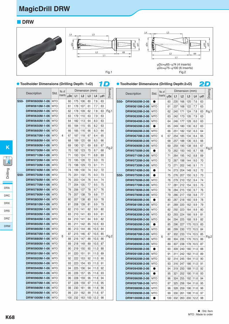
K68 K69
K
Dril
ling
Dril
ling
K
MagicDrill DRW
DRW
Toolholder Dimensions (Drilling Depth:2×D)
Description Std.No. of Inserts
Dimension (mm)
Dra
win
g
φDc L1 L2 L3 L4 φd1
S50- DRW0600M-2-06 ●
4
60 235 166 120 7.6 63
Fig.1
DRW0610M-2-06 MTO 61 237 168 122 7.7 63
DRW0620M-2-06 MTO 62 240 171 124 7.8 63
DRW0630M-2-06 MTO 63 242 173 126 7.9 63
DRW0640M-2-06 MTO 64 246 177 128 8.0 63
DRW0650M-2-06 ● 65 249 180 130 8.2 63
Fig.2
DRW0660M-2-06 MTO 66 251 182 132 8.3 64
DRW0670M-2-06 MTO 67 254 185 134 8.4 65
DRW0680M-2-06 MTO 68 257 188 136 8.5 66
DRW0690M-2-06 MTO 69 259 190 138 8.6 67
DRW0700M-2-06 ● 70 262 193 140 8.7 68
DRW0710M-2-06 MTO 71 264 195 142 8.8 69
DRW0720M-2-06 MTO 72 267 198 144 9.0 70
DRW0730M-2-06 MTO 73 271 202 146 9.1 71
DRW0740M-2-06 ● 74 273 204 148 9.2 72
S50- DRW0750M-2-06 ●
6
75 276 207 150 9.3 73
Fig.2
DRW0760M-2-06 MTO 76 279 210 152 9.4 74
DRW0770M-2-06 MTO 77 281 212 154 9.5 75
DRW0780M-2-06 MTO 78 284 215 156 9.7 76
DRW0790M-2-06 MTO 79 286 217 158 9.8 77
DRW0800M-2-06 ● 80 287 218 160 9.9 78
DRW0810M-2-06 MTO 81 289 220 162 9.9 79
DRW0820M-2-06 MTO 82 292 223 164 9.9 80
DRW0830M-2-06 MTO 83 293 224 166 9.9 81
DRW0840M-2-06 MTO 84 294 225 168 9.9 82
DRW0850M-2-06 ● 85 296 227 170 10.5 83
DRW0860M-2-06 MTO 86 299 230 172 10.5 84
DRW0870M-2-06 MTO 87 302 233 174 10.5 85
DRW0880M-2-06 MTO 88 304 235 176 10.5 86
DRW0890M-2-06 MTO 89 307 238 178 10.5 87
DRW0900M-2-06 ● 90 309 240 180 11.0 88
DRW0910M-2-06 MTO 91 311 242 182 11.0 89
DRW0920M-2-06 MTO 92 314 245 184 11.0 90
DRW0930M-2-06 MTO 93 316 247 186 11.0 91
DRW0940M-2-06 ● 94 319 250 188 11.0 92
DRW0950M-2-06 ● 95 321 252 190 11.6 93
DRW0960M-2-06 MTO 96 324 255 192 11.6 94
DRW0970M-2-06 MTO 97 325 256 194 11.6 95
DRW0980M-2-06 MTO 98 328 259 196 11.6 96
DRW0990M-2-06 MTO 99 330 261 198 11.6 97
DRW1000M-2-06 ● 100 332 263 200 12.2 98
2D2D2D
φ50
69L2
L1
L3L4
φd1
φDc
φDc
L3L4
69L2L1
φ50
φd1
φDc=φ65~φ74 (4 inserts)φDc=φ75~φ100 (6 inserts)
Fig.1 Fig.2
Description Std.No. of Inserts
Dimension (mm)
Dra
win
g
φDc L1 L2 L3 L4 φd1
S50- DRW0600M-1-06 MTO
4
60 175 106 60 7.6 63
Fig.1
DRW0610M-1-06 MTO 61 176 107 61 7.7 63
DRW0620M-1-06 MTO 62 178 109 62 7.8 63
DRW0630M-1-06 MTO 63 179 110 63 7.9 63
DRW0640M-1-06 MTO 64 182 113 64 8.0 63
DRW0650M-1-06 MTO 65 184 115 65 8.2 63
Fig.2
DRW0660M-1-06 MTO 66 185 116 66 8.3 64
DRW0670M-1-06 MTO 67 187 118 67 8.4 65
DRW0680M-1-06 MTO 68 189 120 68 8.5 66
DRW0690M-1-06 MTO 69 190 121 69 8.6 67
DRW0700M-1-06 MTO 70 192 123 70 8.7 68
DRW0710M-1-06 MTO 71 193 124 71 8.8 69
DRW0720M-1-06 MTO 72 195 126 72 9.0 70
DRW0730M-1-06 MTO 73 198 129 73 9.1 71
DRW0740M-1-06 MTO 74 199 130 74 9.2 72
S50- DRW0750M-1-06 MTO
6
75 201 132 75 9.3 73
Fig.2
DRW0760M-1-06 MTO 76 203 134 76 9.4 74
DRW0770M-1-06 MTO 77 204 135 77 9.5 75
DRW0780M-1-06 MTO 78 206 137 78 9.7 76
DRW0790M-1-06 MTO 79 207 138 79 9.8 77
DRW0800M-1-06 MTO 80 207 138 80 9.9 78
DRW0810M-1-06 MTO 81 208 139 81 9.9 79
DRW0820M-1-06 MTO 82 210 141 82 9.9 80
DRW0830M-1-06 MTO 83 210 141 83 9.9 81
DRW0840M-1-06 MTO 84 210 141 84 9.9 82
DRW0850M-1-06 MTO 85 211 142 85 10.5 83
DRW0860M-1-06 MTO 86 213 144 86 10.5 84
DRW0870M-1-06 MTO 87 215 146 87 10.5 85
DRW0880M-1-06 MTO 88 216 147 88 10.5 86
DRW0890M-1-06 MTO 89 218 149 89 10.5 87
DRW0900M-1-06 MTO 90 219 150 90 11.0 88
DRW0910M-1-06 MTO 91 220 151 91 11.0 89
DRW0920M-1-06 MTO 92 222 153 92 11.0 90
DRW0930M-1-06 MTO 93 223 154 93 11.0 91
DRW0940M-1-06 MTO 94 225 156 94 11.0 92
DRW0950M-1-06 MTO 95 226 157 95 11.6 93
DRW0960M-1-06 MTO 96 228 159 96 11.6 94
DRW0970M-1-06 MTO 97 228 159 97 11.6 95
DRW0980M-1-06 MTO 98 230 161 98 11.6 96
DRW0990M-1-06 MTO 99 231 162 99 11.6 97
DRW1000M-1-06 MTO 100 232 163 100 12.2 98
Toolholder Dimensions (Drilling Depth: 1×D) 1D1D1D
: Std. ItemMTO : Made to order
DRA
DRC
DRX
DRS
DRZ
DRW
K-edited.indd 68 25.08.2016 15:40:32
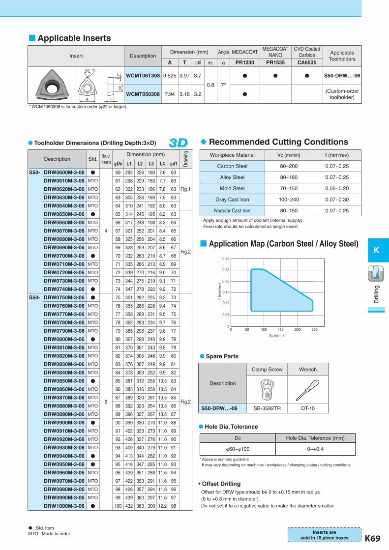
K68 K69
K
Dril
ling
Dril
ling
K
Toolholder Dimensions (Drilling Depth:3×D) 3D3D3DDescription Std.
No. of Inserts
Dimension (mm)
Dra
win
g
φDc L1 L2 L3 L4 φd1
S50- DRW0600M-3-06 ●
4
60 295 226 180 7.6 63
Fig.1
DRW0610M-3-06 MTO 61 298 229 183 7.7 63
DRW0620M-3-06 MTO 62 302 233 186 7.8 63
DRW0630M-3-06 MTO 63 305 236 189 7.9 63
DRW0640M-3-06 MTO 64 310 241 192 8.0 63
DRW0650M-3-06 ● 65 314 245 195 8.2 63
Fig.2
DRW0660M-3-06 MTO 66 317 248 198 8.3 64
DRW0670M-3-06 MTO 67 321 252 201 8.4 65
DRW0680M-3-06 MTO 68 325 256 204 8.5 66
DRW0690M-3-06 MTO 69 328 259 207 8.6 67
DRW0700M-3-06 ● 70 332 263 210 8.7 68
DRW0710M-3-06 MTO 71 335 266 213 8.9 69
DRW0720M-3-06 MTO 72 339 270 216 9.0 70
DRW0730M-3-06 MTO 73 344 275 219 9.1 71
DRW0740M-3-06 ● 74 347 278 222 9.2 72
S50- DRW0750M-3-06 ●
6
75 351 282 225 9.3 73
Fig.2
DRW0760M-3-06 MTO 76 355 286 228 9.4 74
DRW0770M-3-06 MTO 77 358 289 231 9.5 75
DRW0780M-3-06 MTO 78 362 293 234 9.7 76
DRW0790M-3-06 MTO 79 365 296 237 9.8 77
DRW0800M-3-06 ● 80 367 298 240 9.9 78
DRW0810M-3-06 MTO 81 370 301 243 9.9 79
DRW0820M-3-06 MTO 82 374 305 246 9.9 80
DRW0830M-3-06 MTO 83 376 307 249 9.9 81
DRW0840M-3-06 MTO 84 378 309 252 9.9 82
DRW0850M-3-06 ● 85 381 312 255 10.5 83
DRW0860M-3-06 MTO 86 385 316 258 10.5 84
DRW0870M-3-06 MTO 87 389 320 261 10.5 85
DRW0880M-3-06 MTO 88 392 323 264 10.5 86
DRW0890M-3-06 MTO 89 396 327 267 10.5 87
DRW0900M-3-06 ● 90 399 330 270 11.0 88
DRW0910M-3-06 MTO 91 402 333 273 11.0 89
DRW0920M-3-06 MTO 92 406 337 276 11.0 90
DRW0930M-3-06 MTO 93 409 340 279 11.0 91
DRW0940M-3-06 ● 94 413 344 282 11.0 92
DRW0950M-3-06 ● 95 416 347 285 11.6 93
DRW0960M-3-06 MTO 96 420 351 288 11.6 94
DRW0970M-3-06 MTO 97 422 353 291 11.6 95
DRW0980M-3-06 MTO 98 426 357 294 11.6 96
DRW0990M-3-06 MTO 99 429 360 297 11.6 97
DRW1000M-3-06 ● 100 432 363 300 12.2 98
Spare Parts
Description
Clamp Screw Wrench
S50-DRW…-06 SB-3592TR DT-10
Dc Hole Dia. Tolerance (mm)
φ60~φ100 0~+0.4
Hole Dia. Tolerance
* Above is numeric guideline. It may vary depending on machines / workpieces / clamping status / cutting conditions.
Offset for DRW type should be 0 to +0.15 mm in radius (0 to +0.3 mm in diameter).Do not set it to a negative value to make the diameter smaller.
• Offset Drilling
: Std. ItemMTO : Made to order
Insert DescriptionDimension (mm) Angle MEGACOAT
MEGACOATNANO
CVD Coated Carbide Applicable
ToolholdersA T φd rε α PR1230 PR1535 CA6535
80° rε
A T
7°φd
WCMT06T308 9.525 3.97 3.7
0.8 7°
● ● ● S50-DRW…-06
WCMT050308 7.94 3.18 3.2 ● (Custom-order toolholder)
* WCMT050308 is for custom-order (φ22 or larger).
Applicable Inserts
Workpiece Material Vc (m/min) f (mm/rev)
Carbon Steel 80~200 0.07~0.25
Alloy Steel 80~160 0.07~0.25
Mold Steel 70~150 0.06~0.20
Gray Cast Iron 100~240 0.07~0.30
Nodular Cast Iron 80~150 0.07~0.25
· Apply enough amount of coolant (internal supply).· Feed rate should be calculated as single insert.
Recommended Cutting Conditions
Inserts are sold in 10 piece boxes
Application Map (Carbon Steel / Alloy Steel)
0.30
0.25
0.20
0.15
0.10
0.05
00 50 100 150 200 250
Vc (m/min)
f (m
m/r
ev)
K-edited.indd 69 25.08.2016 15:40:33
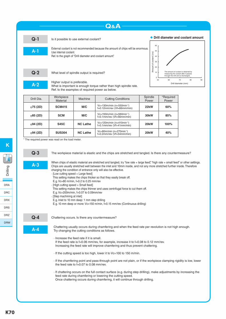
K70 K71
K
Dril
ling
Dril
ling
K
Q&A
Q-1 Is it possible to use external coolant?
A-1External coolant is not recommended because the amount of chips will be enormous.Use internal coolant.Ref. to the graph of “Drill diameter and coolant amount”.
Q-2 What level of spindle output is required?
A-2Higher output is preferable.What is important is enough torque rather than high spindle rate.Ref. to the examples of required power as below.
Drill Dia.Workpiece
MaterialMachine Cutting Conditions
SpindlePower
*RequiredPower
φ75 (2D) SCM415 M/C Vc=130m/min (n=550min-1)f=0.12mm/rev (Vf=66mm/min) 22kW 60%
φ85 (2D) SCM M/C Vc=150m/min (n=560min-1)f=0.1mm/rev (Vf=56mm/min) 30kW 85%
φ94 (2D) S45C NC Lathe Vc=120m/min (n=410min-1)f=0.1mm/rev (Vf=41mm/min) 20kW 100%
φ94 (2D) SUS304 NC Lathe Vc=80m/min (n=270min-1)f=0.2mm/rev (Vf=54mm/min) 20kW 40%
* The required power was read on the load meter.
Q-3 The workpiece material is elastic and the chips are stretched and tangled. Is there any countermeasure?
A-3When chips of elastic material are stretched and tangled, try “low rate + large feed”, “high rate + small feed” or other settings.Chips are usually stretched well between the inlet and 10mm inside, and not any more stretched further inside. Therefore charging the condition of entrance only will also be effective.· [Low cutting speed + Large feed] This setting makes the chips thicker so that they easily break off. E.g. Vc=80 m/min, f=0.2 to 0.25 mm/rev· [High cutting speed + Small feed] This setting makes the chips thinner and uses centrifugal force to cut them off. E.g. Vc=200m/min, f=0.07 to 0.09mm/rev· [Step machining at inlet] E.g. Inlet to 10 mm deep: 1 mm step drilling E.g. 10 mm deep or more: Vc=150 m/min, f=0.15 mm/rev (Continuous drilling)
Drill diameter and coolant amount
500
10
20
30
40
50
60
60 70 80 90
Drill diameter (mm)
The amount of coolant is obtained by measuring the coolant after it passes through the drill and is discharged.
Am
ount
of c
oola
nt (ℓ
/min)
Q-4 Chattering occurs. Is there any countermeasure?
A-4Chattering usually occurs during chamfering and when the feed rate per revolution is not high enough.Try changing the cutting conditions as follows.
· Increase the feed rate if it is small. If the feed rate is f=0.06 mm/rev, for example, increase it to f=0.08 to 0.12 mm/rev. Increasing the feed rate will improve chamfering and thus prevent chattering.
· If the cutting speed is too high, lower it to Vc=100 to 150 m/min.
· If the chamfering point and pass-through point are not plain, or if the workpiece clamping rigidity is low, lower the feed rate to f=0.07 to 0.08 mm/rev.
· If chattering occurs on the full contact surface (e.g. during step drilling), make adjustments by increasing the feed rate during chamfering or lowering the cutting speed. Once chattering occurs during chamfering, it will continue through drilling.
DRA
DRC
DRX
DRS
DRZ
DRW
K-edited.indd 70 25.08.2016 15:40:34
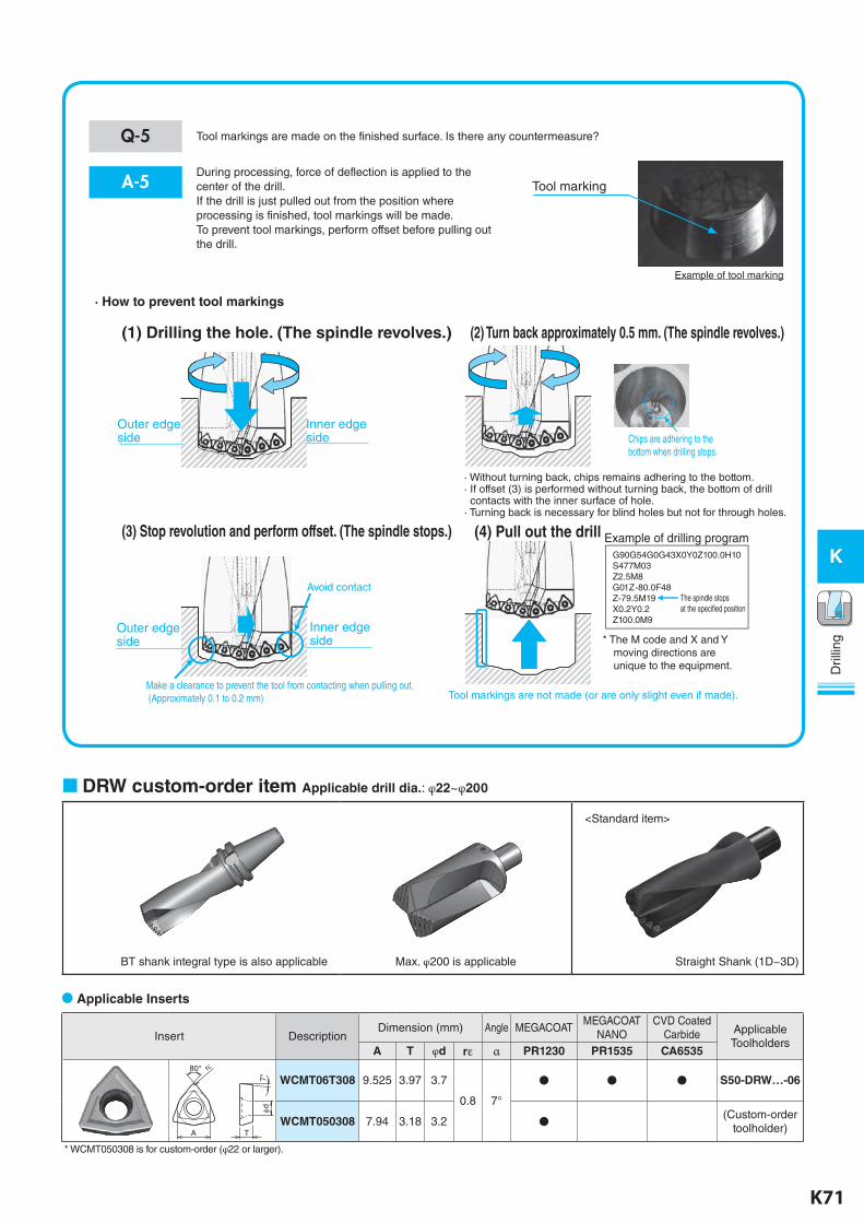
K70 K71
K
Dril
ling
Dril
ling
K
DRW custom-order item Applicable drill dia.: φ22~φ200
BT shank integral type is also applicable Straight Shank (1D~3D)Max. φ200 is applicable
Insert DescriptionDimension (mm) Angle MEGACOAT
MEGACOATNANO
CVD Coated Carbide Applicable
ToolholdersA T φd rε α PR1230 PR1535 CA6535
80° rε
A T
7°φd
WCMT06T308 9.525 3.97 3.7
0.8 7°
● ● ● S50-DRW…-06
WCMT050308 7.94 3.18 3.2 ● (Custom-order toolholder)
* WCMT050308 is for custom-order (φ22 or larger).
<Standard item>
Applicable Inserts
Q-5 Tool markings are made on the finished surface. Is there any countermeasure?
A-5During processing, force of deflection is applied to the center of the drill.If the drill is just pulled out from the position where processing is finished, tool markings will be made.To prevent tool markings, perform offset before pulling out the drill.
Tool marking
· How to prevent tool markings
(1) Drilling the hole. (The spindle revolves.) (2) Turn back approximately 0.5 mm. (The spindle revolves.)
(3) Stop revolution and perform offset. (The spindle stops.) (4) Pull out the drill
· Without turning back, chips remains adhering to the bottom.· If offset (3) is performed without turning back, the bottom of drill contacts with the inner surface of hole.· Turning back is necessary for blind holes but not for through holes.
Make a clearance to prevent the tool from contacting when pulling out. (Approximately 0.1 to 0.2 mm) Tool markings are not made (or are only slight even if made).
Avoid contact
G90G54G0G43X0Y0Z100.0H10S477M03Z2.5M8 G01Z-80.0F48 Z-79.5M19X0.2Y0.2 Z100.0M9
Example of drilling program
The spindle stops at the specified position
Outer edge side
Inner edge side
Outer edgeside
Inner edge side * The M code and X and Y
moving directions are unique to the equipment.
Chips are adhering to the bottom when drilling stops.
Example of tool marking
K-edited.indd 71 25.08.2016 15:40:36