Embed Size (px)
Citation preview

Drum Coupling ABC-V
Industrial Clutch Parts Ltd
IndustrialClutch.com - No.1 International Stock Holding Distributor - Contact us for a free quotation:T: +44 (0) 1663 734 627 E: [email protected] www.IndustrialClutch.com
SIBRE - Siegerland-Bremsen GmbH – Auf der Stücke 1-5 – D-35708 Haiger, Germany Tel.: +49 2773 94000 – Fax: +49 2773 9400-10 – e-mail: [email protected] – www.sibre.de
P:\CATALOGUES\EN CATALOGUES\DOC-CATALOGUE\11 Components\C2 Drum Couplings\EN Drum Couplings ABC-V___10_2012_catalogue.doc
Drum Coupling ABC-V
B06 20 246 E-EN Page 4 / 24
10.2012
1 Application
The drum coupling of the Sibre ABC-V series is especially designed for the use in rope drum drives. It is used for the transfer of medium and high torques as rope drum couplings in crane hoisting gear, conveyance, stackers, ship unloaders, container cranes as well as in heavy, rough smelting works. Torques of up to 1025 kNm and radial loads of up to 550 kN can be transferred with a maximum coupling diameter of 1025 mm. The design of the SIBRE drum coupling is performed on the basis of the steel-iron-guidelines (Stahl-Eisen-Betriebsblatt) SEB 666 212. The exchangeability regarding connection dimensions with series on the market is ensured. The following drawings 1 and 2 show the typical arrangement of a rope drum drive in a crane installation. Drawing 1 shows the direct displacement of the rope drum over a rigid hub on the drive output pin. This unrecommended construction leads to a structurally undefined suspension. In practice such a connection requires a difficult to achieve precision in assembly and alignment. Misalignment during assembly or sagging of the foundation with this hub causes significant additional loads in the drive shaft, which in turn lead to damage in the drive gearing or in the bearings, or to fatigue failure on the shaft.
Drawing 1 Drawing of a double drum drive with quadruple supported shaft (structurally undefined case).

Drum Coupling ABC-V
Industrial Clutch Parts Ltd
IndustrialClutch.com - No.1 International Stock Holding Distributor - Contact us for a free quotation:T: +44 (0) 1663 734 627 E: [email protected] www.IndustrialClutch.com
SIBRE - Siegerland-Bremsen GmbH – Auf der Stücke 1-5 – D-35708 Haiger, Germany Tel.: +49 2773 94000 – Fax: +49 2773 9400-10 – e-mail: [email protected] – www.sibre.de
P:\CATALOGUES\EN CATALOGUES\DOC-CATALOGUE\11 Components\C2 Drum Couplings\EN Drum Couplings ABC-V___10_2012_catalogue.doc
Drum Coupling ABC-V
B06 20 246 E-EN Page 5 / 24
10.2012
Drawing 2 shows the standard support of the rope drum over a drum coupling on the transmission output shaft. The drum coupling serves as a joint that also allows limited axial displacements. As a result the connection is structurally defined and the side load on the drive shaft is significantly reduced.
Drawing 2 Shows a double drum drive with drum couplings. The driven shaft and the rope drum are supported in a structurally defined way. Drawing 3 shows the use of a drum coupling in a single drum drive. The drum coupling is designed as a loose bearing with length compensation. The axial forces developing due to the inertial forces and rope flow have to be absorbed by the oppositely lying vertical bearing of the rope drum. The vertical bearing is usually constructed with a spherical roller bearing as a “fixed bearing”.
Drawing 3 Single drum drive
SIBRE ALC coupling with brake disc
SIBRE ABC Drum coupling „loose bearing“
Vertical bearing “fixed bearing”

Drum Coupling ABC-V
Industrial Clutch Parts Ltd
IndustrialClutch.com - No.1 International Stock Holding Distributor - Contact us for a free quotation:T: +44 (0) 1663 734 627 E: [email protected] www.IndustrialClutch.com
SIBRE - Siegerland-Bremsen GmbH – Auf der Stücke 1-5 – D-35708 Haiger, Germany Tel.: +49 2773 94000 – Fax: +49 2773 9400-10 – e-mail: [email protected] – www.sibre.de
P:\CATALOGUES\EN CATALOGUES\DOC-CATALOGUE\11 Components\C2 Drum Couplings\EN Drum Couplings ABC-V___10_2012_catalogue.doc
Drum Coupling ABC-V
B06 20 246 E-EN Page 6 / 24
10.2012
2 Description and Characteristics
Drawing 3.1
Wear grooves
Wear cam
Lubricating pipe connection
Outer pressure ring
Drum roll
Bleeder hole
Lip seal
Casing
Cover screws
Outer cover
Coupling hub
Locking ring
Lip seal

Drum Coupling ABC-V
Industrial Clutch Parts Ltd
IndustrialClutch.com - No.1 International Stock Holding Distributor - Contact us for a free quotation:T: +44 (0) 1663 734 627 E: [email protected] www.IndustrialClutch.com
SIBRE - Siegerland-Bremsen GmbH – Auf der Stücke 1-5 – D-35708 Haiger, Germany Tel.: +49 2773 94000 – Fax: +49 2773 9400-10 – e-mail: [email protected] – www.sibre.de
P:\CATALOGUES\EN CATALOGUES\DOC-CATALOGUE\11 Components\C2 Drum Couplings\EN Drum Couplings ABC-V___10_2012_catalogue.doc
Drum Coupling ABC-V
B06 20 246 E-EN Page 7 / 24
10.2012
The drum coupling largely consists of a hub part and a casing part that are fit above each other axially. Drill holes are arranged in the parting plane throughout the diameter of both parts. The power transmission of the hub part onto the casing part occurs with positive locking. Hardened barrel rollers are fit into the drill holes, which are formed from the two circular gearings, as power transmission elements. The sealing of the coupling is achieved through double-sided covers with lip seals. This prevents escape of lubricant from the coupling, and the intrusion of dirt from outside into the coupling. The semicircular gearing of the hub over the outer diameter is crowned. Together with the arched drum roll it is possible for the hub to oscillate relative to the casing part, therefore angular displacement and axial shifting are also possible. The coupling casing has an attachment flange with which it is fixed to the front wall of the drum roll. The transmission of momentum between the coupling and the drum roll occurs partially by friction closure, and partially by positive locking by the oppositely lying camming surfaces on the casing. Grade 10.9 high-tension bolts are to be used as connection bolts. The coupling is built with visual wear and position display. Using a wear cam on the casing part and wear grooves on the hub part the wear on the coupling gearing can be easiliy checked from the side of the coupling. The wear cam further serves for checking the axial location of the coupling casing to the coupling hub. The drum couplings of the ABC-V series, that transfers high radial loads in addition to high torques, are characterized by the following features:
Compensation of angular displacement up to +/- 1° Depending on the size of the coupling axial shifting from up to +/- 4mm to up to +/- 10mm.
The max. angular displacement and max. axial shifting must not be fully exploited simultaneously (see information in the OM). The standard drum coupling is not suited for the transfer of axial loads.
Due to the adjustability of the arched drum roll the sliding within the gearing at an angular displacement is limited, which significantly reduces tear due to relative movements.
A high overload safety is the result of the robust design. The power transmission between the coupling hub, the drum roll, and the coupling’s exterior
part additionally leads to smoothed tooth flanks. There is a strain hardening of the material structure which improves the wear resistance.
Due to the convex and concave fit of the drum rolls to the coupling hub and the coupling’s exterior part the forces are spread across a large contact surface which leads to favourable compressive stresses (drawing 4).
Fr
FU
Drawing 4
Drum Coupling ABC-V
Industrial Clutch Parts Ltd
IndustrialClutch.com - No.1 International Stock Holding Distributor - Contact us for a free quotation:T: +44 (0) 1663 734 627 E: [email protected] www.IndustrialClutch.com
SIBRE - Siegerland-Bremsen GmbH – Auf der Stücke 1-5 – D-35708 Haiger, Germany Tel.: +49 2773 94000 – Fax: +49 2773 9400-10 – e-mail: [email protected] – www.sibre.de
P:\CATALOGUES\EN CATALOGUES\DOC-CATALOGUE\11 Components\C2 Drum Couplings\EN Drum Couplings ABC-V___10_2012_catalogue.doc
Drum Coupling ABC-V
B06 20 246 E-EN Page 8 / 24
10.2012
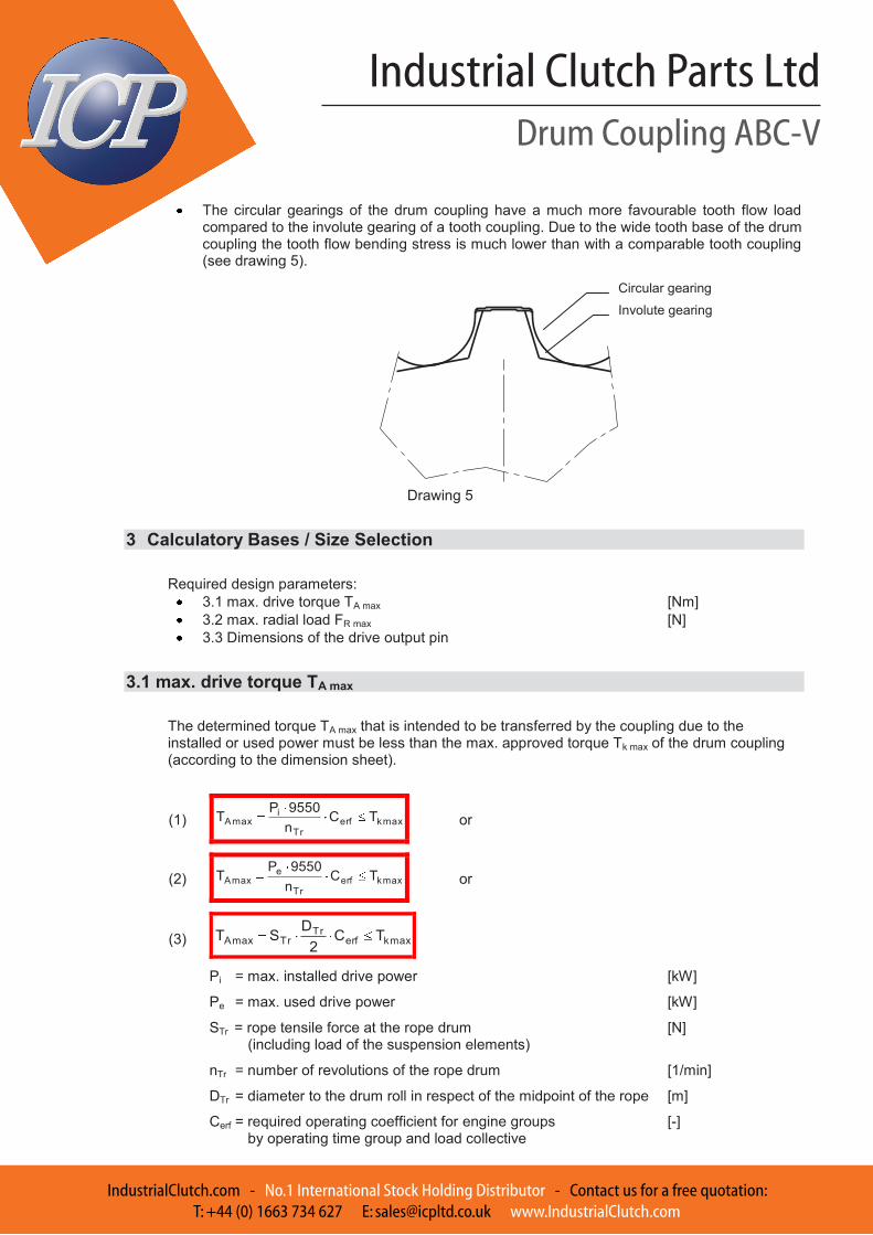
The circular gearings of the drum coupling have a much more favourable tooth flow load
compared to the involute gearing of a tooth coupling. Due to the wide tooth base of the drum coupling the tooth flow bending stress is much lower than with a comparable tooth coupling (see drawing 5).
Drawing 5
3 Calculatory Bases / Size Selection Required design parameters:
3.1 max. drive torque TA max [Nm] 3.2 max. radial load FR max [N] 3.3 Dimensions of the drive output pin
3.1 max. drive torque TA max The determined torque TA max that is intended to be transferred by the coupling due to the installed or used power must be less than the max. approved torque Tk max of the drum coupling (according to the dimension sheet).
(1) maxkerfTr
imaxA TC
n9550PT or
(2) maxkerfTr
emaxA TC
n9550P
T or
(3) maxkerfTr
TrmaxA TC2
DST
Pi = max. installed drive power [kW]
Pe = max. used drive power [kW]
STr = rope tensile force at the rope drum [N] (including load of the suspension elements)
nTr = number of revolutions of the rope drum [1/min]
DTr = diameter to the drum roll in respect of the midpoint of the rope [m]
Cerf = required operating coefficient for engine groups [-] by operating time group and load collective
Involute gearing
Circular gearing

Drum Coupling ABC-V
Industrial Clutch Parts Ltd
IndustrialClutch.com - No.1 International Stock Holding Distributor - Contact us for a free quotation:T: +44 (0) 1663 734 627 E: [email protected] www.IndustrialClutch.com
SIBRE - Siegerland-Bremsen GmbH – Auf der Stücke 1-5 – D-35708 Haiger, Germany Tel.: +49 2773 94000 – Fax: +49 2773 9400-10 – e-mail: [email protected] – www.sibre.de
P:\CATALOGUES\EN CATALOGUES\DOC-CATALOGUE\11 Components\C2 Drum Couplings\EN Drum Couplings ABC-V___10_2012_catalogue.doc
Drum Coupling ABC-V
B06 20 246 E-EN Page 9 / 24
10.2012
Table 1 operating coefficient Cerf
*) To increase the lifetime of the coupling concerning the wear especially at
crane systems with high lift heights and high speeds, e.g. cable cranes but also production cranes working in three shifts it is recommended to raise the operating coefficient Cerf seen in table 1 by 20% up to 40%.
(4) 60000VSP TrTr
e
VTr = rope speed at the drum roll in respect to the midpoint of the rope [m/min]
(5) TrTrTr nDV
3.2 max. radial load FR max The support of the rope drum occurs by the vertical bearing (fixed bearing) on one side, and by the drum coupling (loose bearing) on the other side. The radial load FR max is the proportion of the rope tensile force that has to be absorbed by the drum coupling. The rope tensile force in turn includes the max. payload as well as the load of the suspension elements.
(6) FF
21Tr i
81.9)mm(S
m1 = max. payload [kg]
m2 = dead weight of the suspension elements [kg]
iF = gear ratio of the pulley
drumtheonarrivinglinesropeofNumber
linesropebearingloadofNumberiF
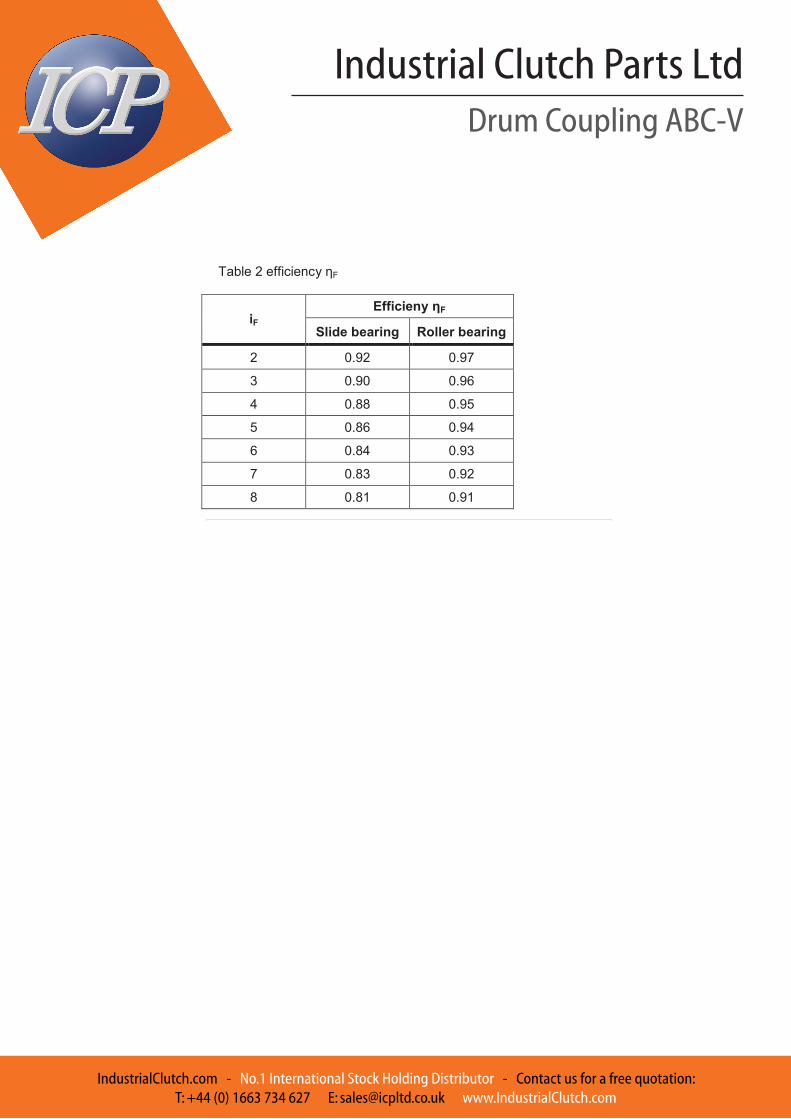
ηF = efficiency of the rope drum and pulley (table 2)
Engine group Cerf*)
DIN 15020 FEM 1.001
1Bm M1;M2;M3 1.25
1Am M4 1.25
2m M5 1.40
3m M6 1.60
4m M7 1.80
5m M8 2.00
Drum Coupling ABC-V
Industrial Clutch Parts Ltd
IndustrialClutch.com - No.1 International Stock Holding Distributor - Contact us for a free quotation:T: +44 (0) 1663 734 627 E: [email protected] www.IndustrialClutch.com
SIBRE - Siegerland-Bremsen GmbH – Auf der Stücke 1-5 – D-35708 Haiger, Germany Tel.: +49 2773 94000 – Fax: +49 2773 9400-10 – e-mail: [email protected] – www.sibre.de
P:\CATALOGUES\EN CATALOGUES\DOC-CATALOGUE\11 Components\C2 Drum Couplings\EN Drum Couplings ABC-V___10_2012_catalogue.doc
Drum Coupling ABC-V
B06 20 246 E-EN Page 10 / 24
10.2012
Table 2 efficiency ηF
iF Efficieny ηF
Slide bearing Roller bearing
2 0.92 0.97
3 0.90 0.96
4 0.88 0.95
5 0.86 0.94
6 0.84 0.93
7 0.83 0.92
8 0.81 0.91

Drum Coupling ABC-V
Industrial Clutch Parts Ltd
IndustrialClutch.com - No.1 International Stock Holding Distributor - Contact us for a free quotation:T: +44 (0) 1663 734 627 E: [email protected] www.IndustrialClutch.com
SIBRE - Siegerland-Bremsen GmbH – Auf der Stücke 1-5 – D-35708 Haiger, Germany Tel.: +49 2773 94000 – Fax: +49 2773 9400-10 – e-mail: [email protected] – www.sibre.de
P:\CATALOGUES\EN CATALOGUES\DOC-CATALOGUE\11 Components\C2 Drum Couplings\EN Drum Couplings ABC-V___10_2012_catalogue.doc
Drum Coupling ABC-V
B06 20 246 E-EN Page 11 / 24
10.2012
Calculation of radial load FR max with multiple rope lines to the rope drum
(7) 281.9m
2SF TrTr
maxR
STr = rope tensile force at the rope drum [N] (including load of the suspension elements)
mTr = dead weight of the rope drum [kg] Case study drawing 6: Case study drawing 7: 4 load bearing rope lines 8 load bearing rope lines 2 rope lines arriving on the drum 2 rope lines arriving on the drum
Calculation of radial load FRmax with one rope line to the rope drum
(8) 2
81.9mlb1SF Tr
TrmaxR
STr = rope tensile force at the rope drum [N] (including load of the suspension elements)
mTr = dead weight of the rope drum [kg]
b = minimum distance from rope to middle of drum roll [mm]
l = distance between middle of fixed bearing to middle of drum roll [mm]
224iF 4
28iF

Drum Coupling ABC-V
Industrial Clutch Parts Ltd
IndustrialClutch.com - No.1 International Stock Holding Distributor - Contact us for a free quotation:T: +44 (0) 1663 734 627 E: [email protected] www.IndustrialClutch.com
SIBRE - Siegerland-Bremsen GmbH – Auf der Stücke 1-5 – D-35708 Haiger, Germany Tel.: +49 2773 94000 – Fax: +49 2773 9400-10 – e-mail: [email protected] – www.sibre.de
P:\CATALOGUES\EN CATALOGUES\DOC-CATALOGUE\11 Components\C2 Drum Couplings\EN Drum Couplings ABC-V___10_2012_catalogue.doc
Drum Coupling ABC-V
B06 20 246 E-EN Page 12 / 24
10.2012
Case study drawing 8: Case study drawing 9: 4 load bearing rope lines 8 load bearing rope lines 1 rope line arriving on the drum 1 rope line arriving on the drum
l l
bb
l l
bb
The max. radial load FR max must be less than than the max. approved coupling radial load Fr max given in the dimension sheet of the drum coupling.
(9) maxrmaxR FF
Corrected radial load FKkorr
A correction/increase of the max. approved radial load Fr max can occur if the max. drive torque TA The unused torque can be converted to increase the max. approved radial load Fr max as follows:
(10) maxrerf
maxAmaxkKkorr F
C)TT(
F
If not all radial load is used a correction of the max. approved torque is not permitted!
3.3 Dimensions of the Transmission Output Pin
Confirming that the diameter of the pin of the transmission output shaft is less than the max. approved drilling diameter according to the dimensions sheet of the chosen drum coupling.
Confirming that the shaft/hub connection is dimensioned sufficiently for the transmitted torque.
414iF 8
18iF

Drum Coupling ABC-V
Industrial Clutch Parts Ltd
IndustrialClutch.com - No.1 International Stock Holding Distributor - Contact us for a free quotation:T: +44 (0) 1663 734 627 E: [email protected] www.IndustrialClutch.com
SIBRE - Siegerland-Bremsen GmbH – Auf der Stücke 1-5 – D-35708 Haiger, Germany Tel.: +49 2773 94000 – Fax: +49 2773 9400-10 – e-mail: [email protected] – www.sibre.de
P:\CATALOGUES\EN CATALOGUES\DOC-CATALOGUE\11 Components\C2 Drum Couplings\EN Drum Couplings ABC-V___10_2012_catalogue.doc
Drum Coupling ABC-V
B06 20 246 E-EN Page 13 / 24
10.2012
4 Calculation Examples
A.) Closed Winch Grasp Unloader
Installed engine power : Pi = 515 kW Engine’s nominal rotation speed : nM = 1230 min-1 Engine gear ratio : iG = 31.5 Radial load that acts on the drum coupling : FR max = 145000 N Engine group : FEM 1.001 = M8 Operating coefficient : Cerf = 2.0
Number of revolutions of the rope drum
5,31min1230
inn
1
G
MTr
= 39 min-1
Max. Output torque
2399550515C
n9550PT erfTr
imaxA
= 252200 Nm
Chosen drum coupling
ABC-V-545 Tkmax = 320000 Nm Frmax = 260000 N
Nm320000TNm252200T maxkmaxA
N260000FN145000F maxrmaxR

Drum Coupling ABC-V
Industrial Clutch Parts Ltd
IndustrialClutch.com - No.1 International Stock Holding Distributor - Contact us for a free quotation:T: +44 (0) 1663 734 627 E: [email protected] www.IndustrialClutch.com
SIBRE - Siegerland-Bremsen GmbH – Auf der Stücke 1-5 – D-35708 Haiger, Germany Tel.: +49 2773 94000 – Fax: +49 2773 9400-10 – e-mail: [email protected] – www.sibre.de
P:\CATALOGUES\EN CATALOGUES\DOC-CATALOGUE\11 Components\C2 Drum Couplings\EN Drum Couplings ABC-V___10_2012_catalogue.doc
Drum Coupling ABC-V
B06 20 246 E-EN Page 14 / 24
10.2012
B.) Main Hoist Max. payload : m1 = 20000 kg Dead weight of the suspension elements : m2 = 7000 kg Dead weight of the rope drum : mTr = 3000 kg Installed engine power : Pi = 450 kW Rated engine speed speed : nM = 900 min-1 Engine gear ratio : iG = 20 Rope drum diameter : DTr = 1.4 m lifting speed : vH = 90 m/min Gear ratio of the pulley : iFl = 2 (see drawing 6) Efficiency of pulley : ηF = 0.97 Engine group : FEM 1.001 = M7 Operating coefficient : Cerf = 1.8
Number of revolutions of the rope drum
20min900
inn
1
G
MTr
= 45 min-1
Max. drive torque based on installed power
8,1459550450C
n9550PT erfTr
imaxA
= 171900 Nm
Max. drive torque based on used power
erf
Tr
emaxA C
n9550P'T
60000
VSP TrTre
97,02
81.9)700020000(i
81,9)mm(SFF
21Tr
= 136500 N
2minm90ivv FHTr
= 180 m/min
60000
180136500Pe = 410 kW
8,1459550410'T maxA
= 156600 Nm
Chosen drum coupling
ABC-V-450 Tkmax = 180000 Nm Frmax = 150000 N
Max. radial load
2
81.930002
1365002
81,9m2S
F TrTrmaxR
= 83000 N
Nm180000TNm156600'T maxkmaxA
N150000FN83000F maxrmaxR

Drum Coupling ABC-V
Industrial Clutch Parts Ltd
IndustrialClutch.com - No.1 International Stock Holding Distributor - Contact us for a free quotation:T: +44 (0) 1663 734 627 E: [email protected] www.IndustrialClutch.com
SIBRE - Siegerland-Bremsen GmbH – Auf der Stücke 1-5 – D-35708 Haiger, Germany Tel.: +49 2773 94000 – Fax: +49 2773 9400-10 – e-mail: [email protected] – www.sibre.de
P:\CATALOGUES\EN CATALOGUES\DOC-CATALOGUE\11 Components\C2 Drum Couplings\EN Drum Couplings ABC-V___10_2012_catalogue.doc
Drum Coupling ABC-V
B06 20 246 E-EN Page 15 / 24
10.2012
Size 280 310 340 400 420 450 530 545 560 600 670 730 800 860
Torque(1) Tk max
[Nm] 35000 45000 55000 80000 120000 180000 250000 320000 410000 500000 600000 770000 950000 1025000
Radial load Fr max
[N] 45000 55000 75000 115000 130000 150000 200000 260000 315000 340000 400000 475000 525000 550000
Weight(3) [kg] 44 54 71 108 135 164 260 294 329 415 549 697 960 1097 Moment
of inertia(3) [kgm²] 0,54 0,82 1,35 2,67 3,7 5,2 11,0 13,2 15,6 22,3 36,3 56,2 105,5 118,4
Finish bore(2)
Ød1minH7 [mm] 100 100 100 120 120 140 160 160 170 200 230 260 290 330
Ød1maxH7 [mm] 140 155 180 210 215 245 290 300 310 330 370 420 450 470
Ød2 [mm] 215 235 275 315 330 370 430 450 465 500 560 620 680 715
Ød3 [mm] 279 309 339 399 419 449 529 544 558 598 668 728 798 835
Ød4 h6 [mm] 280 310 340 400 420 450 530 545 560 600 670 730 800 860
Ød5 [mm] 198 218 258 298 310 350 410 430 440 470 530 590 650 680
Ød6 [mm] 400 420 450 510 550 580 650 665 680 710 780 850 940 1025
Ød7 [mm] 19 19 24 24 24 24 24 24 24 28 28 28 28 34
a1 [mm] 15 15 20 20 20 20 25 25 25 35 35 35 40 40
e1 [mm] 45 45 60 60 60 60 65 65 65 81 81 81 86 86
e2 [mm] 48 50 61 61 65 67 69 78 78 88 88 90 92 92
g1 [mm] 7.5 7.5 10 10 10 10 10 10 10 10 10 10 10 10
g2 [In] G1/8 G1/8 G1/4 G1/4 G1/4 G1/4 G1/4 G1/4 G1/4 G1/4 G1/4 G1/4 G1/4 G1/4
h1 [mm] 27,5 27 23 24,5 30 32 35 45 45 40 40 50 50 50
h2 [mm] 34,5 37 35,5 37 45 47 50 60 65 60 60 70 70 70
Sh9 [mm] 360 380 400 460 500 530 580 590 600 640 700 760 830 900
Øk1 [mm] 360 380 400 460 500 530 600 615 630 660 730 800 875 945
l [mm] 170 175 185 220 240 260 315 330 350 380 410 450 500 500
r [mm] 2.5 2.5 2.5 2.5 2.5 2.5 2.5 4 4 4 4 4 4 4 Axial tolerance
max +/- [mm] 4 4 5 6 6 6 6 6 6 8 8 8 10 10
(1) The given torques do not refer to the shaft-hub connection. These must be checked if necessary. (2) Other tolerances possible by arrangement. (3) With respect to max. finish bore Ød1.
5 Dimension sheet ABC-V
Table 3
Design hub bore see part 7
Design hole spacings see part 6

Drum Coupling ABC-V
Industrial Clutch Parts Ltd
IndustrialClutch.com - No.1 International Stock Holding Distributor - Contact us for a free quotation:T: +44 (0) 1663 734 627 E: [email protected] www.IndustrialClutch.com
SIBRE - Siegerland-Bremsen GmbH – Auf der Stücke 1-5 – D-35708 Haiger, Germany Tel.: +49 2773 94000 – Fax: +49 2773 9400-10 – e-mail: [email protected] – www.sibre.de
P:\CATALOGUES\EN CATALOGUES\DOC-CATALOGUE\11 Components\C2 Drum Couplings\EN Drum Couplings ABC-V___10_2012_catalogue.doc
Drum Coupling ABC-V
B06 20 246 E-EN Page 16 / 24
10.2012
6 Connection coupling rope drum
The material of the flanged wheel should have a min. yield strength of 320 N/mm². We recommend the use of screws in accordance with DIN931, 933 with strength class 10.9 with disks in accordance with DIN125-300HV or screws in accordance with DIN6914 with high tensile disks in accordance with DIN6916 for attaching the SIBRE drum coupling to the rope drum. Screws in accordance with DIN912 with strength class 8.8 are to be used as cover screws. Table 4
Drawing 6
Drawing7
Size S F8/h9 a2 min. Ød4 F8 Ød17 Øk1 t4 min. t6 y min.
[mm] [mm] [mm] Thread Quantity [mm] [mm] [mm] [mm]
280 360 30 280 M16 10 360 15 0.10 60
310 380 30 310 M16 10 380 15 0.10 60
340 400 40 340 M20 10 400 20 0.10 70
400 460 40 400 M20 10 460 20 0.10 70
420 500 40 420 M20 10 500 20 0.15 80
450 530 40 450 M20 14 530 20 0.15 80
530 580 50 530 M20 14 600 25 0.20 80
545 590 50 545 M20 26 615 25 0.20 100
560 600 50 560 M20 26 630 25 0.20 100
600 640 60 600 M24 26 660 35 0.20 120
670 700 60 670 M24 26 730 35 0.20 120
730 760 60 730 M24 26 800 35 0.20 120
800 830 70 800 M24 32 875 40 0.20 120
860 900 70 860 M30 32 945 40 0.20 120

Drum Coupling ABC-V
Industrial Clutch Parts Ltd
IndustrialClutch.com - No.1 International Stock Holding Distributor - Contact us for a free quotation:T: +44 (0) 1663 734 627 E: [email protected] www.IndustrialClutch.com
SIBRE - Siegerland-Bremsen GmbH – Auf der Stücke 1-5 – D-35708 Haiger, Germany Tel.: +49 2773 94000 – Fax: +49 2773 9400-10 – e-mail: [email protected] – www.sibre.de
P:\CATALOGUES\EN CATALOGUES\DOC-CATALOGUE\11 Components\C2 Drum Couplings\EN Drum Couplings ABC-V___10_2012_catalogue.doc
Drum Coupling ABC-V
B06 20 246 E-EN Page 17 / 24
10.2012
Hole spacings size 280-420 Hole spacings size 450-530
Hole spacings size 545-730 Hole spacings size 800-860
Drawing 8

Drum Coupling ABC-V
Industrial Clutch Parts Ltd
IndustrialClutch.com - No.1 International Stock Holding Distributor - Contact us for a free quotation:T: +44 (0) 1663 734 627 E: [email protected] www.IndustrialClutch.com
SIBRE - Siegerland-Bremsen GmbH – Auf der Stücke 1-5 – D-35708 Haiger, Germany Tel.: +49 2773 94000 – Fax: +49 2773 9400-10 – e-mail: [email protected] – www.sibre.de
P:\CATALOGUES\EN CATALOGUES\DOC-CATALOGUE\11 Components\C2 Drum Couplings\EN Drum Couplings ABC-V___10_2012_catalogue.doc
Drum Coupling ABC-V
B06 20 246 E-EN Page 18 / 24
10.2012
7 Feather key connection
The given values are valid for drillings in accordance with DIN6885-1. In principle every feather key connection must be checked for surface pressure. Feather keyways in accordance with BS 46, ANSI B17.1 or other standards are also possible. We request consultation for other connection methods such as involute splines in accordance with DIN5480
1 Feather key Table 5 feather keys in accordance with DIN 6885 part 1
2x feather key 180°
2x feather key 120° right
2x feather key 120° left
Drawing 9
Drill hole Ød1 across 44 50 58 65 75 85 95 110 130
up to 50 58 65 75 85 95 110 130 150
Feather key Width b: 14 16 18 20 22 25 28 32 36 Height h: 9 10 11 12 14 14 16 18 20
Keyseat Width b: 14 16 18 20 22 25 28 32 36 Depth t1 5.5 6 7 7.5 9 9 10 11 12
Tolerance +0.2 +0.3
Hubgroove Width b: 14 16 18 20 22 25 28 32 36 Depth t2 3.8 4.3 4.4 4.9 5.4 5.4 6.4 7.4 8.4
Tolerance +0.2 +0.3
r2 max. 0.4 0.6 1
min. 0.25 0.4 0.7
Drill hole Ød1 across 150 170 200 230 260 290 330 380 440
up to 170 200 230 260 290 330 380 440 500
Feather key Width b: 40 45 50 56 63 70 80 90 100 Height h: 22 25 28 32 32 36 40 45 50
Keyseat Width b: 40 45 50 56 63 70 80 90 100 Depth t1 13 15 17 20 20 22 25 28 31
Tolerance +0.3
Hubgroove Width b: 40 45 50 56 63 70 80 90 100 Depth t2 9.4 10.4 11.4 12.4 12.4 14.4 15.4 17.4 19.5
Tolerance +0.3
r2 max. 1 1.6 2.5
min. 0.7 1.2 2
Drum Coupling ABC-V
Industrial Clutch Parts Ltd
IndustrialClutch.com - No.1 International Stock Holding Distributor - Contact us for a free quotation:T: +44 (0) 1663 734 627 E: [email protected] www.IndustrialClutch.com
SIBRE - Siegerland-Bremsen GmbH – Auf der Stücke 1-5 – D-35708 Haiger, Germany Tel.: +49 2773 94000 – Fax: +49 2773 9400-10 – e-mail: [email protected] – www.sibre.de
P:\CATALOGUES\EN CATALOGUES\DOC-CATALOGUE\11 Components\C2 Drum Couplings\EN Drum Couplings ABC-V___10_2012_catalogue.doc
Drum Coupling ABC-V
B06 20 246 E-EN Page 19 / 24
10.2012
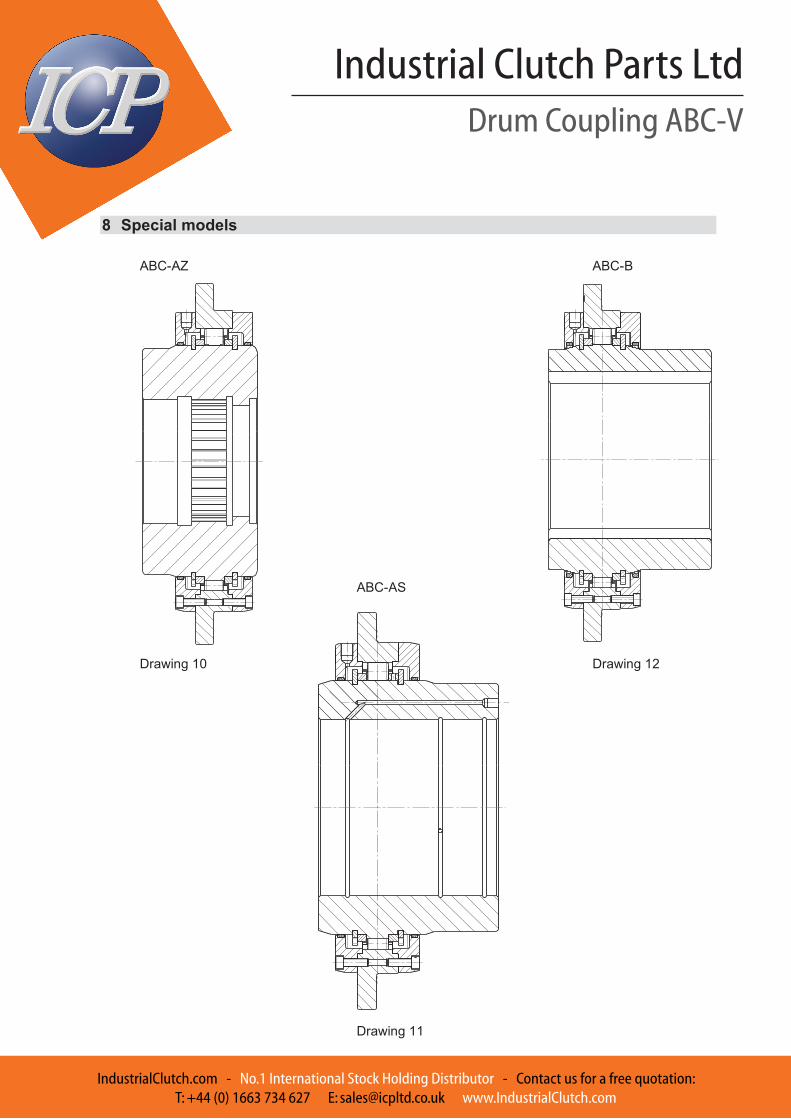
8 Special models
ABC-AZ ABC-B
ABC-AS Drawing 10 Drawing 12
Drawing 11

Drum Coupling ABC-V
Industrial Clutch Parts Ltd
IndustrialClutch.com - No.1 International Stock Holding Distributor - Contact us for a free quotation:T: +44 (0) 1663 734 627 E: [email protected] www.IndustrialClutch.com
SIBRE - Siegerland-Bremsen GmbH – Auf der Stücke 1-5 – D-35708 Haiger, Germany Tel.: +49 2773 94000 – Fax: +49 2773 9400-10 – e-mail: [email protected] – www.sibre.de
P:\CATALOGUES\EN CATALOGUES\DOC-CATALOGUE\11 Components\C2 Drum Couplings\EN Drum Couplings ABC-V___10_2012_catalogue.doc
Drum Coupling ABC-V
B06 20 246 E-EN Page 20 / 24
10.2012
9 Wear Display
The wear display serves to detect the wear at the gearing. With increasing wear the wear cam will cover the wear groove more and more caused by the torsion of the coupling hub in relation to the casing. If the wear cam is centrically covered, then the max. wear is reached and the drum coupling has to be replaced. The layout of the wear display simplifies a lateral check. The max. permitted wear is shown in Table 6. In applications with two load directions the max. permitted wear has to be halved. This must be indicated during ordering so that the appropriate wear grooves are produced.
without wear with max. wear Drawing 13 Drawing 14
without wear with max. wear
Drawing 15 Drawing 16 Table 6 coupling wear
Coupling size Max. permitted wear m
280-400 6 mm
420-860 8 mm
wear grooves
wear cam