Embed Size (px)
Citation preview

Drug delivery with microsecondlaser pulses into gelatin
HanQun Shangguan, Lee W. Casperson, Alan Shearin, Kenton W. Gregory,and Scott A. Prahl
Photoacoustic drug delivery is a technique for localized drug delivery by laser-induced hydrodynamicpressure following cavitation bubble expansion and collapse. Photoacoustic drug delivery wasinvestigated on gelatin-based thrombus models with planar and cylindrical geometries by use of onemicrosecond laser pulses. Solutions of a hydrophobic dye in mineral oil permitted monitoring ofdelivered colored oil into clear gelatin-based thrombus models. Cavitation bubble development andphotoacoustic drug delivery were visualized with flash photography. This study demonstrated thatcavitation is the governing mechanism for photoacoustic drug delivery, and the deepest penetration ofcolored oil in gels followed the bubble collapse. Spatial distribution measurements revealed thatcolored oil could be driven a few millimeters into the gels in both axial and radial directions, and thepenetration was less than 500 µm when the gelatin structure was not fractured.Key words: Ablation, photoacoustic transients, localized drug delivery, cavitation bubble, laser
thrombolysis. r 1996 Optical Society of America
1. Introduction
Pharmacological therapy for the treatment of reste-nosis, thrombosis, and ischemic heart diseases mayeventually become clinically practical through thelocalized delivery of therapeutic agents.1–3 A pri-mary advantage of localized drug delivery over tradi-tional drug delivery is that, with the former, sideeffects such as bleeding and stroke can be avoided,because high concentrations of pharmacologic agentsare delivered directly to the treatment site withminimal systemic exposure to the medication.Localized drug delivery for vascular applications istypically achieved by use of balloon-based cathetersystems.2,4–7 For example, a double-balloon cath-eter is used for delivering drug into vessel wall tissue
H-Q. Shangguan is with the Department of Electrical Engineer-ing, Portland State University, Portland, Oregon 97201, and theOregon Medical Laser Center, Portland, Oregon 97225. L. W.Casperson is with the Department of Electrical Engineering,Portland State University, Portland, Oregon 97201. A. Shearinis with the OregonMedical Laser Center, Portland, Oregon 97225,and Palomar Medical Technologies, Inc., Beverly, Massachusetts01915. K. W. Gregory and S. A. Prahl are with the OregonMedical Laser Center, Portland, Oregon 97225, and OregonHealth Sciences University, Portland, Oregon 97201.Received 20 November 1995.0003-6935@96@193347-11$10.00@0r 1996 Optical Society of America
by inflation of two balloons in an artery with apressurized drug-filled volume between them.2 Theprimary problems associated with current investiga-tional systems are their cumbersome size and longinflation times as well as the risk of medial injuryoccurring during the balloon inflation process, thuspotentially limiting the benefits of localized drugdelivery.Photoacoustic drug delivery is a technique for
delivering drugs to localized areas.8,9 Unlike thetechniques for enhancing local delivery of moleculesthat use laser-induced shock waves,10,11 photoacous-tic drug delivery uses a laser pulse to generate acavitation bubble in a blood vessel owing to theabsorption of laser energy by targets 1e.g., blood clots2or surrounding liquids 1e.g., blood2. The cavitationbubble expands and collapses hundreds of microsec-onds after the laser pulse. The hydrodynamic pres-sure arising from the expansion and collapse of thecavitation bubble can force the drug into the clot orthe vessel wall. One can perform photoacousticdrug delivery by timing the laser pulses to becoincident with an injected bolus of drug. Thedelivery system for photoacoustic drug delivery couldconsist of only two elements: an optical fiber orlight guide for delivering laser pulses and cathetertubing for injecting drugs. A fluid-core laser cath-eter has been used to remove thrombus 1blood clot2with a pulsed dye laser without damaging the vessel
1 July 1996 @ Vol. 35, No. 19 @ APPLIED OPTICS 3347

wall tissue.12 Photoacoustic drug delivery with sucha fluid-core laser catheter may be an alternativemethod to current techniques for localized drugdelivery.Previous studies have established that cavitation
bubbles can be formed in a liquid or on a solid target,depending on where the laser energy is absorbed.Cavitation bubbles play an important role in pulsedlaser ablation of tissue and in laser lithotripsy.13–16Van Leeuwen et al. demonstrated that cavitationbubbles make it possible to ablate tissue in a noncon-tact mode through a layer of blood or saline, and theforceful expansion of a cavitation bubble inducesmechanical damage in adjacent tissue in the form ofdissections.13 A study by Vogel et al. suggested thatcavitation-induced dilatation of vessel walls occur-ring in pulsed laser angioplasty can be prevented bydivision of the laser pulse energy into a prepulsewith low energy and an ablation pulse with highenergy.14 Rink et al. reported that cavitation bubblecollapse is the governing factor for fragmentationand disruption during laser lithotripsywithmicrosec-ond laser pulses.15 The stone is progressively frag-mented by stresses exceeding its tensile strengthand by fatigue. In clinical trials of laser thromboly-sis, Gregory suggested that the removal of thrombusmight be attributed to the acoustic phenomena fromvaporization and ejection of materials.17 Francis etal. recently demonstrated that ultrasound could beused to accelerate the transport of fibrinolytic agentsinto clots as a result of the ultrasound effects medi-ated by cavitation and microstreaming.18 However,whether the laser-induced hydrodynamic pressurecan be used to drive drugs into thrombus or tissue forlocalized drug delivery remained to be investigated.This study was motivated by the possibility of
using laser-induced hydrodynamic pressure to driveclot-dissolving enzymes into clots or vessel walltissue for the enhancement of laser thrombolysis.Specifically, the aim of this study has been to identifythe mechanisms of photoacoustic drug deliverythrough investigating how the target material, laserenergy, absorption coefficient, fiber size, repetitionrate, and number of pulses affect the spatial distribu-tion of photoacoustically delivered drug. The pro-cess of photoacoustic drug delivery was visualized byuse of flash photography, and the acoustic pressuretransients were measured with a piezoelectric poly-vinylidene fluorid 1PVDF2 transducer.Photoacoustic drug delivery was studied with gela-
tin-based thrombus models that eliminated the bio-logical variation of thrombus and provided transpar-ent samples for spatial distribution measurement.Solutions of a hydrophobic red dye in mineral oilwere irradiated with a microsecond laser pulse toinitiate drug delivery. We found that photoacousticdrug delivery was associated with cavitation bubbleformation and sound emission and that the deepestpenetration followed the collapse of the cavitationbubble.
3348 APPLIED OPTICS @ Vol. 35, No. 19 @ 1 July 1996
2. Materials and Methods
A. Laser Delivery
A flash-lamp-pumped dye laser 1Palomar MedicalTechnologies2 operating at 504 nmwas used to createcavitation bubbles 1Fig. 12. This wavelength corre-sponded to the peak absorption of the light-absorb-ing dye used. The pulse duration was 1.3 µs 1fullwidth at half-maximum2. The laser energies variedfrom 30 to 100 mJ. Pulse-to-pulse energy variationwas less than 5%. The repetition rate ranged from1 to 10 Hz. The laser pulses were delivered bymeans of step-index fused-silica optical fibers with300–1000-µm core diameters. The light was al-ways absorbed by the liquid surrounding the fibertip. Three irradiation configurations were used.First, a flat optical fiber tip was perpendicular to aplanar target 3Fig. 21a24. Second, a flat optical fibertip was coaxial with a cylindrical channel 3Fig. 21b24.Third, a side-firing fiber 1MicroQuartz Sciences2 wascoaxial in a cylindrical channel but with irradiationperpendicular to the axis of the channel 3Fig. 21c24.
B. Preparation of Thrombus Models
The thrombus was modeled with 3.5% gelatin 160–300 bloom2. The percentage was determined by theweight ratio of gelatin to water. The bloom numberis the standard method for indicating the toughnessof gels and is a measure of surface tension. Higherbloom numbers indicate stronger gels. No attemptwas made to correlate the bloom number with anyspecific clots in this study, although the range stud-ied was similar to that of typical clot toughness.The gelatin–water mixture was heated to 60 °C withstirring until it became clear. Liquid gelatinsamples were poured into 1-cm cuvettes and moldedto form 2–3-cm-thick thrombus models with planaror cylindrical geometries. To simulate cardiovascu-lar applications, the channels were constructed ,2mm in diameter under the assumption that somenarrowing of the normal 2–4-mm adult human coro-nary artery is likely in a thrombotic lesion. The
Fig. 1. Experimental setup for spatial distribution measure-ment, flash photography, and acoustic pressure measurement.

samples were transparent, and it was easy to uselight microscopy to discriminate any colored sub-stances from clear gelatin.
C. Preparation of Drug Models
We used solutions of a hydrophobic dye 1D&C Red#17, Warner–Jenkinson2 in mineral oil 1PaddockLaboratories2 as a model for the drug. The hydro-phobic dye was used because the gels were waterbased and staining of the surface by the dye wasundesirable. We added the dye to the mineral oil toachieve the desired absorption coefficient. We ob-served that no dye passively diffused into gelatin incontrol samples. The absorption coefficient of asolution was linearly proportional to the concentra-tion of the dye in the oil: 0.0367 g of dye in 30-mLoil gave an absorption coefficient of 300 cm21 at 504nm. The absorption coefficients in our experimentsvaried from 50 to 300 cm21. The dye–oil mixturewas heated to 100 °C with stirring until the appear-ance became uniform and was then cooled to roomtemperature. A solution of 300 cm21 was saturatedat room temperature after 4 h when the dye began toprecipitate, and the absorption coefficient dropped to250 cm21. The use of a sonicator 1Medelco2 for 10min after the dye–oil solution was heated delayedthe precipitation time for at least another hour.
D. Spatial Distribution Measurement
1. Planar GeometryAll planar targets were covered with 1.5 cm ofcolored oil. The target was clear gelatin ,2 cmthick. Ten laser pulses were delivered through anoptical fiber into the colored oil for each experiment1except in the study involving pulse number, in which
Fig. 2. Schematic illustration of three irradiation configurationsand the methods used for measuring the spatial distribution ofphotoacoustically delivered dye in clear gels. The top and sideviews of samples irradiated by perpendicular, coaxial, and sideirradiation are shown in 1a2, 1b2, and 1c2, respectively.
10–100 pulses were delivered2. The fiber tip waspositioned 1–5 mm above the target surface, asshown in Fig. 1. The laser energy output wasmeasuredwith a joulemeter 1J50LP,MolectronDetec-tor2 before and after each irradiation. Followingphotoacoustic drug delivery, the samples were mea-sured under a stereo-optical microscope 1SZ6045,Olympus2. The stained areas in the clear gels indi-cated the presence of photoacoustically deliveredcolored oil. Figure 21a2 shows how the spatial distri-butions of colored oil in the gelatin were measured.The stained areas consisted of two parts: a hemi-sphere with width w and height hmix and somecolored cracks extending a depth hcrack. The dis-tances w, hmix, and hcrack were measured on all foursides of each sample. The spatial distribution of thecolored oil in the gels was measured as functions oflaser energy 130–100 mJ2, absorption coefficient ofthe oil 150–300 cm212, fiber size 1300–1000 µm2,gelatin strength 160–300 bloom2, repetition rate 11–10Hz2, pulse number 11–1002, and fiber position 11–5mm above the ablated target2.
2. Cylindrical GeometryA clear gelatin sample with a 2-mm cylindricalchannel was filled with colored oil. Fifty laserpulses were delivered coaxially through a cleavedfiber tip or perpendicularly through a side-firingfiber tip. The fiber tip was located in the middle ofthe channel. Following laser irradiation, the gelsamples were carefully removed from the cuvetteand then fixed in 10% formalin. They were thensectioned into 2-mm-thick slices through both theirradiated and the nonirradiated sites after thecolored oil in the channel was washed away with theformalin. To assess whether the process of photo-acoustic drug delivery could enhance intravascularrecanalization, we measured the lumenal areas andthen compared them with control data measuredfrom nonirradiated sections. The uniform penetra-tion of colored oil in the gels was defined as hmix
coax,whereas the colored cracks underneath hmix
coax weredefined as hcrack
coax . The measuring method is shownin Fig. 21b2.
E. Visualization of Photoacoustic Drug Delivery
Photoacoustic drug delivery was visualized withflash photography 1Fig. 12. A triggerable CCD cam-era 1CV-251, Protec2 was used to photograph theprocesses. Each picture was a single event and wasrepeated three times for each parameter set. Thebubble size was reproducible to 5% before the bubblecollapse. The appearance of cavitation bubbles var-ied widely after the bubble collapse. A strobe 1MVS-2601, EG&G2 with a 5-µs pulse duration 1full widthat half-maximum2 was used for illumination at anadjustable delay time 110–5000 µs2 controlled by adigital delay generator 1DG535, Stanford ResearchSystems2. The generator was triggered by the laserpulse by use of a photodiode 1UDT Instruments2 thatwas attached to the laser delivery fiber. The delay
1 July 1996 @ Vol. 35, No. 19 @ APPLIED OPTICS 3349

time was defined as the period between the end ofthe laser pulse and the peak of the flash of light fromthe strobe.
F. Acoustic Pressure Measurement
The acoustic pressure measurements were intendedfor relative measurements of the acoustic pressuretransients created by different laser parameters.A PVDF transducer 1Hydrosonics2 with a rise time of,1 µs was placed under the cuvette 1Fig. 12. Theacoustic signals were recorded on a digital storageoscilloscope 1DSA602A, Tektronix2 through an ampli-fier 1Hydrosonics2. Only the maximum signals wererecorded for the comparative study of the acousticpressure transients.
G. Statistical Evaluation
All values are expressed as mean 6 standard devia-tion. The statistical significance of differences inthe penetration of photoacoustically delivered dye ingels was determined by a two-tailed Student’s t-test.An unpaired t-test was used to analyze the data aseach parameter varied. Differences were consid-ered significant at p # 0.05.
3. Results
A. Spatial Distribution Measurement
For simplicity, most of experiments were conductedon the samples with planar geometry. A cylindricalgeometry was used to simulate the boundaries ofvessel walls and to show the clinical possibilities ofphotoacoustic drug delivery. The effects of laserparameters on photoacoustic drug delivery werequalitatively the same for planar and cylindricalgeometries, but the penetration was less in thecylindrical case. We defined w and wcoax as stainedwidth 1Fig. 22. The parameters hmix, hcrack, hmix
coax, andhcrackcoax were defined as penetration.
1. Planar GeometryThe spatial distribution measurements are summa-rized in Table 1. As the parameters increased,some increased the penetration 1laser energy, absorp-tion coefficient, and pulse number2, some decreasedthe penetration 1gelatin strength, fiber size, and the
3350 APPLIED OPTICS @ Vol. 35, No. 19 @ 1 July 1996
distance between the fiber and target surface2, andone parameter had no significant effect on penetra-tion 1repetition rate2.Both penetration depths hmix and hcrack increased
significantly with increases in laser energy, absorp-tion, and number of pulses. The penetration hmixincreased linearly, and hcrack increasedwith a steadilyincreasing slope. The stained width w was rela-tively independent of the laser energy and absorp-tion coefficient, but it increased significantly as thenumber of pulses increased.Increasing the gelatin strength, spot sizes, and the
distance between a fiber tip and target surfacecaused both the penetration and the stained width todecrease significantly. Linear decreases in hmix wereobserved, whereas hcrack decreased with steadilydecreasing slope for each parameter. We found thatthe colored oil was easily driven into the low-strength gel samples following irradiation. For ex-ample, the colored oil was driven into the weaker gel160 bloom2 after one or two pulses, but at least fivepulses were needed to push the colored oil into thestronger gel samples 1300 bloom2. We observed thatduring irradiation with a 300-µm fiber the solutionwas explosively ejected and the solution in front ofthe fiber tip became dark, i.e., it was burnt. Irradia-tion with a 600-µm fiber was more violent than thatwith a 1000-µm fiber, but no explosive ejection wasobserved. The repetition rate did not affect thepenetration 1p 5 0.15–0.952 or the stained width1p , 0.42 significantly.
2. Cylindrical GeometryAcleaved fiber tip 1300 µm in core diameter2was usedto deliver 50 laser pulses of 30 mJ at 3 Hz into thelight-absorbing liquid 1300 cm212 coaxially. The tar-get was 3.5% gelatin 1175 bloom2. After laser irradia-tion the lumen area increased to 125%, and thecolored oil was driven into the gels up to 1.5 mm3hcrack
coax in Fig. 21b24. The maximum depth hmixcoax of a
uniformly stained layer was less than 250 µm. Thestained width wcoax of the wall was ,4 mm. One ofthese sectioned samples is illustrated in Fig. 3.Aside-firing fiber was also evaluated. The output
spot size of this tip was ,700 µm in diameter. Fifty
Table 1. Spatial Distribution Measurements of Colored Oil in Gels with Planar Geometry a
Delivery Parameters Measurements
Energy1mJ2
AbsorptionCoefficient
1cm212Numberof Pulses
GelatinStrength 1Bloom2
FiberSize 1µm2
FiberPosition 1mm2
RepetitionRate 1Hz2
hmix60.05 1mm2
hcrack60.2 1mm2
w60.2 1mm2
30 = 100 300 10 175 1000 1 3 0.12 = 0.18 0.1 = 0.5 2.0 = 2.360 50 = 300 10 175 1000 1 3 0.07 = 0.15 0.0 = 0.4 1.9 = 2.060 300 10 = 100 175 1000 1 3 0.15 = 0.53 0.4 = 1.9 2.0 = 2.860 300 10 60 = 300 1000 1 3 0.25 = 0.10 0.8 = 0.2 2.1 = 1.560 300 10 175 300 = 1000 1 3 0.18 = 0.15 1.0 = 0.4 3.2 = 2.060 300 10 175 1000 1 = 5 3 0.15 = 0.06 0.4 = 0.0 2.0 = 1.060 300 10 175 1000 1 1 = 10 0.13 = 0.16 0.1 = 0.4 1.8 = 2.1
aAll data are mean 6 standard deviation of five samples.

laser pulses of 40 mJ at 3 Hz were delivered. Thecorresponding radiant exposure is 104 [email protected] penetration was comparable with that of planargeometry for the same laser parameters. The mea-surements revealed that the deeper penetration wasmore easily achieved by side delivery than by coaxialdelivery. The light photomicrography in Fig. 4 illus-trates that the colored oil is deeply driven into thegel 1,1 mm2 on the light-delivery side and onlysuperficially 1,100 µm2 elsewhere.
B. Visualization of Photoacoustic Drug Delivery
In Fig. 5 a series of pictures shows the process ofphotoacoustic drug delivery on a gelatin sample 1175bloom2 with planar geometry. The bubbles wereformed in colored oil 1300 cm212 with 30-mJ pulsesdelivered through a 300-µm core-diameter fiber.This corresponds to a laser radiant exposure of 424mJ@mm2. The fiber tip was positioned 1 mm above
Fig. 3. Top view of colored-oil distribution in a 2-mm channelthrough gelatin 1175 bloom2 with cylindrical geometry after 50pulses of 30-mJ laser energy through a 300-µm core-diameterfiber in 300-cm21 colored oil. The laser energy was deliveredcoaxially. Extensive shadows are present because this sectionwas 2 mm thick.
Fig. 4. Top view of colored-oil distribution in a 2-mm channelthrough gelatin 1175 bloom2 with cylindrical geometry after 50pulses of 40-mJ laser energy through a side-firing fiber in300-cm21 colored oil. The laser energy was delivered perpendicu-lar to the channel wall, as indicated by the arrow.
the target. The camera flash occurred 25–1500 µsafter the laser pulse. The cavitation bubble ini-tially grew and interacted with the nearby gel. Themaximum horizontal diameter of the bubble mea-sured 2.4 mm and was reached at 110 µs. At ,250µs after the laser pulse the bubble shrank to aminimum size and then rebounded slightly. A sec-ond maximum was observed at ,300 µs, and thebubble then shrank until ,415 µs. At ,500 µs alarger and less distinct shadow was seen, which maycorrespond to a final rebound of the bubble. Thisbubble size oscillationwas reproducible. The bubblestarted its final collapse to the gel at ,650 µs, andthe maximum penetration into the gel was reachedat ,1 ms. The shape of the bubbles was not repro-ducible after the second rebound of the cavitationbubble. Evidently, the colored oil was driven intothe gel as the result of the expansion and collapse ofthe bubble, and the deeper penetration of colored oilin gels was achieved following the collapse. Weobserved that the colored oil was pushed back to thesurface because of the resistance of gels when thegels with higher mechanical strength 1e.g., $175bloom2 were used during single-pulse irradiation.This is seen at 1.5 ms.Photoacoustic drug delivery on a gelatin sample
1175 bloom2 with cylindrical geometry is shown inFig. 6. In this experiment a 30-mJ laser pulse wasdelivered through a 300-µm core-diameter fiber intocolored oil with absorption coefficient 300 cm21.The channel wall was dilated during the cavitationbubble expansion. The maximum dilation wasreached after ,100 µs and amounted to 120% of theinitial channel diameter. During the bubble col-lapse the channel wall invaginated, and the solutionin the channel was pushed away from the fiber tip inboth lateral and forward directions, which causeddilation and invagination along the channel walluntil the end of the event. It took approximately 5ms for the channel to return its original shape after alaser pulse. The minimum diameter was ,90% ofthe original value. We took the images on onesample rather than on a fresh sample each time toavoid misinterpretation of initial intrasample de-fects before irradiation.Figure 7 shows a cavitation bubble developing
between the side-firing fiber tip and the surface ofthe cylindrical channel after the delivery of a 40-mJ-energy laser pulse. The corresponding radiant expo-sure is ,104 mJ@mm2. The other parameters werethe same as those in Fig. 6. The images wererecorded between 25 µs and 1ms after laser radiation.The cavitation bubble was formed directly on theside surface of the fiber tip where the laser energywas absorbed. The maximal development of thelaser-induced elliptical cavitation bubble is seen at100 µs after the laser pulse. The correspondingbubble diameter and height were 1.7 and 1.2 mm,respectively. The bubble reached its minimum sizeat 250 µs and penetrated,1.5mm into the gelatin at,1 ms. No bubble oscillation was observed. The
1 July 1996 @ Vol. 35, No. 19 @ APPLIED OPTICS 3351

Fig. 5. Side views of photoacoustic drug delivery on gelatin 1175 bloom2 with a planar geometry. A single pulse of 30-mJ laser energywas delivered through a 300-µm diameter fiber. The absorption coefficient was 300 cm21. The fiber was located 1 mm above the gelsurface. The backgrounds of four photographs 1300–500 µs2 are lighter than the rest because of different illumination. The bubble sizewas reproducible to 5% before the second rebound of the cavitation bubble 1500 µs2. The appearance of cavitation bubbles varied widelyafter 500 µs.
bubble did not penetrate the channel wall when thelaser pulse was less than a 5 mJ. The bubblepenetrated deeper into the gel at higher laser ener-gies 1i.e., .40 mJ2. No displacement of the tip wasobserved during the irradiation. In this experi-ment the distance between the bubble site and thetarget was ,400 µm, and the gelatin was as thick as4 mm. The initial channel wall surface was as not
3352 APPLIED OPTICS @ Vol. 35, No. 19 @ 1 July 1996
so smooth as a planar surface and was often associ-ated with some defects. These differences may con-tribute to the differences in the bubble formation inFigs. 5 and 7, although the spatial distributionmeasurements were comparable. The images weretaken on one sample, as explained above.Flash photography also led to the following obser-
vations 1pictures not shown2: 112 Increasing energy,

Fig. 6. Side views of photoacoustic drug delivery on gelatin 1175 bloom2 in a cylindrical geometry. A single pulse of 30-mJ laser energywas delivered through a 300-µm diameter fiber into 300-cm21 colored oil. The absorption coefficient was 300 cm21. The laser energywas delivered coaxially. The arrow indicates the place where the deepest penetration was observed.
absorption coefficient, and radiant exposure increasethe bubble size and the penetration of colored oil inthe gel and delay the time of the maximum bubblesize. For example, the bubble diameter was 2.7 mmat 110 µs when a 100-mJ laser pulse was deliveredinto the solution 1300 cm212 through a 1000-µm fiberpositioned 1 mm above the target, whereas it was 1.6mm at 45 µs as 30 mJ of energy was deliveredinstead. 122 Increasing the target strength does notaffect the bubble size unless the expanding bubbleinteracts with the target. If this occurs both the
bubble size and the penetration of colored oil arereduced. 132 Increasing the distance between thefiber tip and the target decreases the penetration ofcolored oil in the gel, creates larger cavitationbubbles, and delays the time of the maximum bubblesize. 142 Cavitation bubbles formed in cylindricalchannels were smaller than those formed in un-bounded solutions because of the boundary effect.152 Multiple pulses affect the bubble formation—sometimes making the bubbles smaller, sometimeslarger compared with the bubbles generated by
1 July 1996 @ Vol. 35, No. 19 @ APPLIED OPTICS 3353

Fig. 7. Side views of photoacoustic drug delivery on gelatin 1175 bloom2with cylindrical geometry. A single pulse of 40-mJ laser energywas delivered perpendicularly to the channel through a side-firing fiber into 300-cm21 colored oil. The white dashed curve shows theedge of the side-firing fiber tip. The dark areas inside the fiber tip are due to the index mismatch at the air–oil interface.
single pulses. The penetration of colored oil intothe gel increases with more pulses.
C. Acoustic Pressure Measurement
Flash photography and a PVDF transducer wereused to correlate the bubble size with the pressuretransients. The acoustic measurements were quali-tative, and themeasured pressuremight be underes-timated because of the slow response of the trans-ducer and the multiple boundaries between theinitial acoustic event and the transducer. We ob-served that the acoustic pressure transients wereproportional to the bubble size and that bubbles ofsimilar size created by different-size fibers gener-ated similar maximum acoustic pressure transients.The acousticmeasurements provided a quick qualita-tive check of the maximum bubble size observedvisually.
4. Discussion
The major objective of this study was to investigatethe feasibility of a photoacoustic technique to deliver
3354 APPLIED OPTICS @ Vol. 35, No. 19 @ 1 July 1996
clot-dissolving enzymes into clots to enhance laserremoval of the clots. We investigated the effects oflaser parameters on the spatial distribution of photo-acoustically delivered colored oil 1a drug model2 ingelatin-based thrombus models. We used clear gelsamples covered with colored oil to determine thespatial distribution of delivered drug. A stainedarea in the clear gel indicated the presence of coloredoil delivered photoacoustically. No dye passivelydiffused into the clear water-based gels. The col-ored oil was driven into the gels following irradia-tion, cavitation bubble formation, and secondaryacoustic emission. When no cavitation bubble wasformed, no gelatin was stained. Normally, deeperpenetration was accompanied by louder poppingsounds. Acoustic pressure transients were de-tected during the expansion and collapse of thecavitation bubble. The spatial measurements alsorevealed that higher pressures resulted in deeperpenetration. These findings suggest that cavitationbubble formation is crucial in photoacoustic drugdelivery and that acoustic events can be used as a

means of monitoring the efficacy of photoacousticdrug delivery in vivo.This study demonstrated that the drug was most
likely driven into the clot by hydrodynamic flow thatwas due to the cavitation bubble formation ratherthan by the acoustic transients arising from thebubble formation, inasmuch as the acoustic tran-sients passed through the sample and reached thetransducer before the colored oil was forced into thegelatin. In this sense, the term photomechanicaldrug delivery may be more appropriate for the typeof drug delivery described in this study. However, itremains unclear whether the acoustic transientscontribute to the delivery through other mechanismsthat might weaken the gelatin before the onset ofhydrodynamic flows.At least four limitations are associated with the
models used in this study. First, the gelatin-basedthrombus models did not work perfectly with mul-tiple-pulse studies because they were easily meltedor fractured; real clots tend to be more durable.Second, it may be harder to deliver oil-based dyethan aqueous dyes because of viscosity effects.Third, the colored oil at high absorption coefficients1e.g., 300 cm212 was easily burnt when laser pulseswith high energy 1e.g., 100 mJ through a 1000-µmcore fiber2 or high radiant exposure 1$212 mJ@mm2
or, say, 60 mJ through a 600-µm core fiber2 wereused. The burnt solution surrounding the fiber tipsometimes caused the photoacoustic delivery processto become nonreproducible. It was observed thatthe color of the solutions sometimes became darkerafter multiple-pulse irradiation. Fourth, all cavita-tion events in this model were initiated at the fibertip. Photoacoustic drug delivery may be signifi-cantly different when the cavitation bubble is formeddirectly on a target because of the absorption of thelaser pulse by the target.
A. Effect of Cavitation Bubble Formation
Photoacoustically delivered colored oil in a planargeometry was uniformly distributed as an invertedhemisphere layer and in a cylindrical geometry as aball-shaped profile. The uniformly stained layerlooked like a dye–gelatin mixture 1i.e., the gel itselfrather than small colored-oil droplets became stained2under light microscopy and could not be washedaway by clear oil or wicked off by a piece of tissuepaper. Colored cracks were formed below the uni-formly stained layer.The shape of colored cracks was not reproducible,
and the cracks were not always associated with theuniformly stained layers. For example, no coloredcracks 1i.e., hcrack 5 02were formed by ten 60-mJ laserpulses through a 1000-µm core fiber in a colored oil150 cm212, but colored cracks 400 µm in depth wereformed by the same laser parameters when a differ-ent colored oil 1300 cm212 was used 1see Table 12.Lightmicroscopy showed that the crackswere formedas the result of defects in gel structure. No defectswere observed in the positions where the cracks were
formed before the irradiation. This suggests thatthe formation of the uniformly stained layers andthat of the cracks aremediated by separate processes.These separate processes can be used to advantagein clinical applications. For example, drugs can beuniformly delivered into a thrombus or deposited inan arterial wall or deeply delivered into plaqueunderneath the thrombus by fracture.Colored oil in a planar geometry was driven into
the gels even when the expanding bubbles had nocontact with the gels 1although the collapsing bubblealways did2. The penetration hmix increased but thestained width w remained relatively constant whenhcrack was zero 3cf. Fig. 21a24. These observationsimply that hmix depends on the hydrodynamic forcesthat arise from both the expansion and the collapse.Auniform colored layer is formedwhen the forces arebelow the yield strength of the gelatin structure,whereas cracks are formed when the forces exceedthose needed to fracture the gelatin.Gross physical displacement of the cuvette contain-
ing the irradiation targets occurred after the laserpulse. The magnitude of the displacement in-creased as the bubble size increased. For example,the cuvette rebounded more than 2 mm when thebubble diameter was ,4 mm, but no displacementwas observed for a 1.3-mm bubble. The directionwas opposite that of laser delivery. The bubbleenergy obtainedwith Rayleigh’s bubble formula15,19,20accounts for only a small fraction of the laser energy1,0.1%2. This raises the question: How was themajority of the energy dissipated during the process?We hypothesize that the delivered laser energy isdissipated mainly through heating, phase changes,acoustic transients, and hydrodynamic flow of liquid.Hydrodynamic flows ultimately lead to movement ofthe cuvette.
B. Geometric Effect
Photoacoustic drug delivery was qualitatively thesame for both planar and cylindrical geometries, butthe penetration was less in the cylindrical case.Flash photography showed that the fiber tip affectedthe cavitation bubble growth: bubbles grew fasterin the radial and forward directions. The bubbledid not move radially and migrated away from thefiber tip on collapse. Strong hydrodynamic flowswere associated with the bubble collapse and may bethe reason that deeper penetration was achieved byperpendicular delivery rather than by coaxial deliv-ery. Collapsing bubbles migrated toward the targetin both perpendicular and side-firing delivery 1seeFigs. 5 and 72. This finding suggests that the side-firing light-delivery devices may be promising forphotoacoustic drug delivery in vascular applications.No mass removal was observed for the samples
with planar geometry. However, in a cylindricalgeometry light microscopy revealed that the lumensize increased by as much as 1.5 mm after multiplepulses. We hypothesize that gelatin removal in thecylindrical channel is due to hydrodynamic flow and
1 July 1996 @ Vol. 35, No. 19 @ APPLIED OPTICS 3355
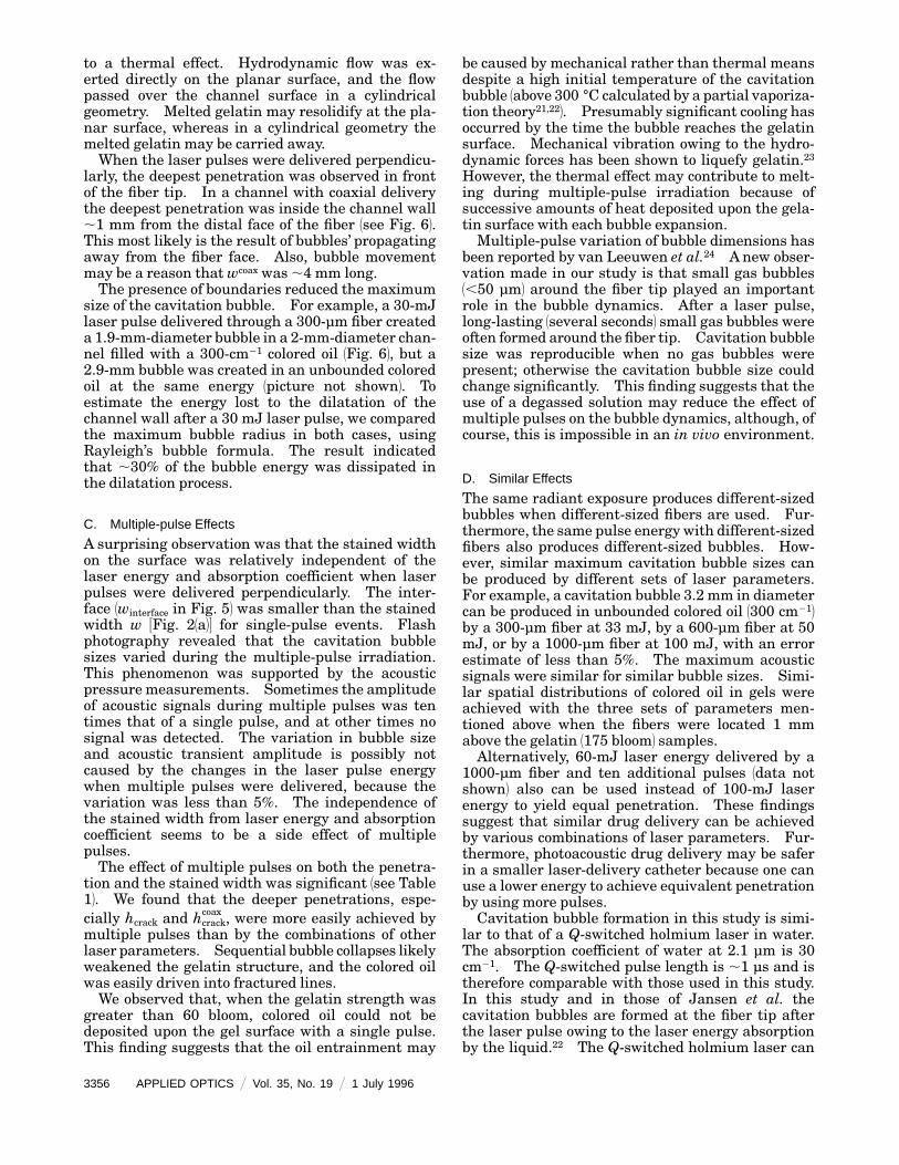
to a thermal effect. Hydrodynamic flow was ex-erted directly on the planar surface, and the flowpassed over the channel surface in a cylindricalgeometry. Melted gelatin may resolidify at the pla-nar surface, whereas in a cylindrical geometry themelted gelatin may be carried away.When the laser pulses were delivered perpendicu-
larly, the deepest penetration was observed in frontof the fiber tip. In a channel with coaxial deliverythe deepest penetration was inside the channel wall,1 mm from the distal face of the fiber 1see Fig. 62.This most likely is the result of bubbles’ propagatingaway from the fiber face. Also, bubble movementmay be a reason thatwcoax was ,4 mm long.The presence of boundaries reduced the maximum
size of the cavitation bubble. For example, a 30-mJlaser pulse delivered through a 300-µm fiber createda 1.9-mm-diameter bubble in a 2-mm-diameter chan-nel filled with a 300-cm21 colored oil 1Fig. 62, but a2.9-mm bubble was created in an unbounded coloredoil at the same energy 1picture not shown2. Toestimate the energy lost to the dilatation of thechannel wall after a 30 mJ laser pulse, we comparedthe maximum bubble radius in both cases, usingRayleigh’s bubble formula. The result indicatedthat ,30% of the bubble energy was dissipated inthe dilatation process.
C. Multiple-pulse Effects
A surprising observation was that the stained widthon the surface was relatively independent of thelaser energy and absorption coefficient when laserpulses were delivered perpendicularly. The inter-face 1winterface in Fig. 52 was smaller than the stainedwidth w 3Fig. 21a24 for single-pulse events. Flashphotography revealed that the cavitation bubblesizes varied during the multiple-pulse irradiation.This phenomenon was supported by the acousticpressuremeasurements. Sometimes the amplitudeof acoustic signals during multiple pulses was tentimes that of a single pulse, and at other times nosignal was detected. The variation in bubble sizeand acoustic transient amplitude is possibly notcaused by the changes in the laser pulse energywhen multiple pulses were delivered, because thevariation was less than 5%. The independence ofthe stained width from laser energy and absorptioncoefficient seems to be a side effect of multiplepulses.The effect of multiple pulses on both the penetra-
tion and the stained width was significant 1see Table12. We found that the deeper penetrations, espe-cially hcrack and hcrack
coax , were more easily achieved bymultiple pulses than by the combinations of otherlaser parameters. Sequential bubble collapses likelyweakened the gelatin structure, and the colored oilwas easily driven into fractured lines.We observed that, when the gelatin strength was
greater than 60 bloom, colored oil could not bedeposited upon the gel surface with a single pulse.This finding suggests that the oil entrainment may
3356 APPLIED OPTICS @ Vol. 35, No. 19 @ 1 July 1996
be caused by mechanical rather than thermal meansdespite a high initial temperature of the cavitationbubble 1above 300 °C calculated by a partial vaporiza-tion theory21,222. Presumably significant cooling hasoccurred by the time the bubble reaches the gelatinsurface. Mechanical vibration owing to the hydro-dynamic forces has been shown to liquefy gelatin.23However, the thermal effect may contribute to melt-ing during multiple-pulse irradiation because ofsuccessive amounts of heat deposited upon the gela-tin surface with each bubble expansion.Multiple-pulse variation of bubble dimensions has
been reported by van Leeuwen et al.24 A new obser-vation made in our study is that small gas bubbles1,50 µm2 around the fiber tip played an importantrole in the bubble dynamics. After a laser pulse,long-lasting 1several seconds2 small gas bubbles wereoften formed around the fiber tip. Cavitation bubblesize was reproducible when no gas bubbles werepresent; otherwise the cavitation bubble size couldchange significantly. This finding suggests that theuse of a degassed solution may reduce the effect ofmultiple pulses on the bubble dynamics, although, ofcourse, this is impossible in an in vivo environment.
D. Similar Effects
The same radiant exposure produces different-sizedbubbles when different-sized fibers are used. Fur-thermore, the same pulse energy with different-sizedfibers also produces different-sized bubbles. How-ever, similar maximum cavitation bubble sizes canbe produced by different sets of laser parameters.For example, a cavitation bubble 3.2 mm in diametercan be produced in unbounded colored oil 1300 cm212by a 300-µm fiber at 33 mJ, by a 600-µm fiber at 50mJ, or by a 1000-µm fiber at 100 mJ, with an errorestimate of less than 5%. The maximum acousticsignals were similar for similar bubble sizes. Simi-lar spatial distributions of colored oil in gels wereachieved with the three sets of parameters men-tioned above when the fibers were located 1 mmabove the gelatin 1175 bloom2 samples.Alternatively, 60-mJ laser energy delivered by a
1000-µm fiber and ten additional pulses 1data notshown2 also can be used instead of 100-mJ laserenergy to yield equal penetration. These findingssuggest that similar drug delivery can be achievedby various combinations of laser parameters. Fur-thermore, photoacoustic drug delivery may be saferin a smaller laser-delivery catheter because one canuse a lower energy to achieve equivalent penetrationby using more pulses.Cavitation bubble formation in this study is simi-
lar to that of a Q-switched holmium laser in water.The absorption coefficient of water at 2.1 µm is 30cm21. The Q-switched pulse length is ,1 µs and istherefore comparable with those used in this study.In this study and in those of Jansen et al. thecavitation bubbles are formed at the fiber tip afterthe laser pulse owing to the laser energy absorptionby the liquid.22 The Q-switched holmium laser can

be used for photoacoustic drug delivery, althoughTable 1 indicates that the penetration will be halfthat of a 577-nm pulsed dye laser in blood 1absorp-tion coefficient of 300 cm212. The pulse duration forthe free-running holmium laser ismuch longer 1,250µs2, and the bubble dynamics are completely differ-ent because the cavitation bubble is formed duringthe laser pulse.In conclusion, we have demonstrated the feasibil-
ity of photoacoustic drug delivery to drive drugs1colored oil2 into thrombus 1a gelatin-based model2.The results of this study indicate that cavitationbubble formation is the governing mechanism forphotoacoustic drug delivery with microsecond laserpulses in light-absorbing liquids. When no cavita-tion bubble was formed, no gelatin was stained.There are two processes in photoacoustic drug deliv-ery: the formation of uniformly stained layers andthe formation of colored cracks. The two separateprocesses may benefit clinical applications. Thedeepest penetration of colored oil in gels follows thecavitation bubble collapse. The penetration wasless than 500 µm when the gelatin structure was notfractured, and the colored oil could be driven a fewmillimeters into the gels in both axial and radialdirections. The results of this study demonstratedthat similar penetration could be achieved by use ofvarious combinations of laser parameters.
Address any correspondence to S. A. Prahl atOregon Medical Laser Center.We thank U. S. Sathyam andM. J. Girsky for their
valuable comments on the manuscript. This re-search was supported in part by the Murdock Foun-dation, Portland, Ore., and the Whitaker Founda-tion, Washington, D.C.
References1. D.A. Dichek, R. F. Neville, J.A. Zwiebel, S. M. Freeman,M. B.
Leon, and W. F. Anderson, ‘‘Seeding of intravascular stentswith genetically engineered endothelial cells,’’ Circulation 80,1347–1353 119892.
2. E. G. Nabel, G. Plautz, and G. J. Nable, ‘‘Site-specific geneexpression in vivo by direct gene transfer into the arterialwall,’’ Science 249, 1285–1288 119902.
3. H. Lin, M. S. Parmacek, G. Morle, S. Bolling, and J. M.Leiden, ‘‘Expression of recombination genes inmyocardium invivo after direct injection of DNA,’’ Circulation 82, 2217–2221119902.
4. E. C. Santoian, M. B. Gravanis, K. Anderberg, N. A. Scott,S. P. Karas, J. E. Schneider, and S. B. King III, ‘‘Use of aporous infusion balloon in swine coronary arteries: lowpressure minimizes arterial damage,’’ Circulation 84, II-591119912.
5. A. Fernndez-Ortiz, B. J. Meyer, A. Mailhac, E. Falk, L.Badimon, J. T. Fallon, V. Fuster, J. H. Chesebro, and J. J.Badimon, ‘‘A new approach for local intravascular drugdelivery: iontophoretic balloon,’’ Circulation 89, 1518–1522119942.
6. H. Wolinsky and M. B. Taubman, ‘‘Local delivery to thearterial wall: pharmacologic and molecular approaches,’’ inCoronary Balloon Angioplasty, R. E. Vlietstra, ed., 1BlackwellScientific, Lakeland, Fla., 19942, pp. 156–186.
7. A. M. Lincoff, E. J. Topol, A. Frieser, and S. G. Ellis, ‘‘Localdrug delivery for prevention of restenosis,’’ Circulation 90,2070–2084 119942.
8. H. Shangguan, L. W. Casperson, A. Shearin, K. W. Gregory,and S. A. Prahl, ‘‘Photoacoustic drug delivery: the effect oflaser parameters on spatial distribution of delivered drug,’’ inLaser-Tissue Interaction VI, S. L. Jacques, ed., Proc. SPIE2391, 394–402 119952.
9. H. Shangguan, L. W. Casperson, A. Shearin, and S. A. Prahl,‘‘Visualization of photoacoustic drug delivery dynamics,’’ La-sers Surg. Med. S7, 4–5 119952.
10. R. C. Zeimer, B. Khoobehi, and R. L. Magin, ‘‘A potentialmethod for local drug and dye delivery in the ocular vascula-ture,’’ Invest. Ophthalmol. Vis. Sci. 29, 1179–1183 119882.
11. T. J. Flotte, S. Lee, H. Zhang, D. MacAuliffe, T. Douki, and A.Doukas, ‘‘Laser-induced stress transients: Applications formolecular delivery,’’ in Laser-Tissue Interaction VI, S. L.Jacques, ed., Proc. SPIE 2391, 202–207 119952.
12. K. W. Gregory and R. R.Anderson, ‘‘Liquid core light guide forlaser angioplasty,’’ IEEE J. QuantumElectron. 26, 2289–2296119902.
13. T. G. van Leeuwen, M. J. van der Veen, R. M. Verdaasdonk,and C. Borst, ‘‘Noncontact tissue ablation by holmium:YSGG laser pulses in blood,’’ Lasers Surg. Med. 11, 26–34119912.
14. A. Vogel, R. Engelhardt, and U. Behnle, ‘‘Minimization ofcavitation effects in pulsed laser ablation—illustrated onlaser angioplasty,’’Appl. Phys. B 62, 173–182 119962.
15. K. Rink, G. Delacretaz, and R. P. Salathe, ‘‘Fragmentationprocess of current laser lithotriptors,’’ Lasers Surg. Med. 16,134–146 119952.
16. A. A. Oraevsky, R. Esenaliev, S. L. Jacques, and F. K. Tittel,‘‘Laser flash photography of cold cavitation-driven ablation intissues,’’ in Laser-Tissue Interaction VI, S. L. Jacques, ed.,Proc. SPIE 2391, 300–307 119952.
17. K. Gregory, ‘‘Laser thrombolysis,’’ in Interventional Cardiol-ogy, E. J. Topol, ed. 1Saunders Company, Philadelphia, Pa.,19942, Vol. 2, Chap. 5, pp. 892–902.
18. C. W. Francis, A. Blinc, S. Lee, and C. Cox, ‘‘Ultrasoundaccelerates transport of recombinant tissue plasminogenactivator into clots,’’ Ultrasound Med. Biol. 21, 419–424119952.
19. O. M. Rayleigh, ‘‘On the pressure developed in a liquid duringthe collapse of a spherical cavity,’’ Philos. Mag. 34, 94–98119172.
20. A. Vogel, S. Busch, K. Jungnickel, and R. Birngruber, ‘‘Mecha-nisms of intraocular photodisruption with picosecond andnanosecond laser pulses,’’ Lasers Surg. Med. 15, 32–43 119942.
21. T. G. van Leeuwen, E. D. Jansen, M. Motamedi, C. Brost, andA. J. Welch, ‘‘Excimer laser ablation of soft tissue: a study ofthe content of rapidly expanding and collapsing bubbles,’’IEEE J. Quantum Electron. 30, 1339–1345 119942.
22. E. D. Jansen, T. G. van Leeuwen, M. Motamedi, C. Brost, andA. J. Welch, ‘‘Partial vaporization model for pulsed mid-infrared laser ablation of water,’’ J. Appl. Phys. 78, 564–571119952.
23. G. K. Batchelor, Introduction to Fluid Dynamics 1CambridgeU. Press, Cambridge, 19802.
24. T. G. van Leeuwen, L. van Erven, J. H. Meertens, M. J. Post,and C. Borst, ‘‘Vapor bubble expansion and implosion: theorigin of ‘mille feuilles’,’’ in Diagnostic and Therapeutic Car-diovascular Interventions III, G. S. Abela, ed., Proc. SPIE1878, 2–12 119932.
1 July 1996 @ Vol. 35, No. 19 @ APPLIED OPTICS 3357