Embed Size (px)
Citation preview

Droplet Photo timing machine
PART NO. 2171612
This is a timer that synchronizes the camera, flash and solenoid valve so that anyone with a SLR camera with tripod and an externalflash will be able to take amazing drop pictures. The timer contains a microprocessor which is programmed 90 different dropletshapes so that the result is as the finest work of art.
Time Required: 10 h depending on experience
Experience Level: Intermediate
Required tools and parts:
Soldering ironSaw and some glue to make the deviceSLR camera, an external flash and a tripod
Bill of Materials:
Qty Jameco SKU Component Name
1 169835 solenoid valve
1 18893 PVC box
1 159485 RCA Jack
1 1216815 Transistor BD139
1 51422 Voltage Regulator 5V 78L05
1 33523 Capacitor 0.33uF
1 544833 capasitor 0.01uF
2 15405 Capasitor 22pf
1 2131039 Resistors 22 x 2, 100, 1K, 1.2K, 10K
1 137891 Crystal
1 878227 Optocoupler
1 112300 IC socket
1 2139111 Microcontroller preloaded with my "droplet controller SW program"
microcontroller with pre-installed software.
1 Wireless flash transmitter and receiver - PT-04 GY
1 216240 Battery holder
1 2125042 DIY circuit proto board
1 151590 Power Connector Panel Mount
1 168242 DC Power plug, 2.5x5.5MM
1 1949470 Cable for the solenoid
1 1945372 Patch cord
Step 1 - Components
Make sure you have received all the components

Step 2 - Additional parts
Make sure you also have:-
camera, digital or analog (with a tripod stand). You can not use a pocket camera. Flash, multimetersome tools, iron tools, some glue, a water container (piece of a pipe)
Step 3 - Patch cord
Strip the patch cord
Step 4 - Sort the parts
Sort the parts as shown in the image
Step 5 - Mount a link wire
1) Mark the PCB with the letters from A to Z and numbers 1-12 as shown in the pictures.2) Create a connection link wire between Q6 and Q9

Step 6 - Mount the optocoupler
It is extremely important that the first component is mounted in the correct position and that it is rotated 180 degrees around!
The picture shows a Sharp PC817, the kit includes a similar, but by a different manufacturer.
Step 7 - Bend the wire

Step 8 - Mount the IC socket
Make sure you have placed the socket in the correct position.
When the IC socket is positioned correctly, it can be advantageous to mount it with a piece of tape (so it stays in place until you havesoldered it).
Step 9 - IC socket pinout
Pinout

Step 10 - Schematic overview
Step 11 - PCB plate from solder side
Check if your PCB looks the same as the one in the picture
Step 12 - Adding the power transistor

Pinout
Step 13 - Adding the power transistor and a link wire connection (#2)
Place the transistor as shown in the picture. Hole H8, I8 and J8Do not solder it yet.One of the leads of the transistor is also linked to wire (# 2)
Step 14 - Bend the transistor feet - make a link wire
Connect H8 and H7. This is link wire (# 2)
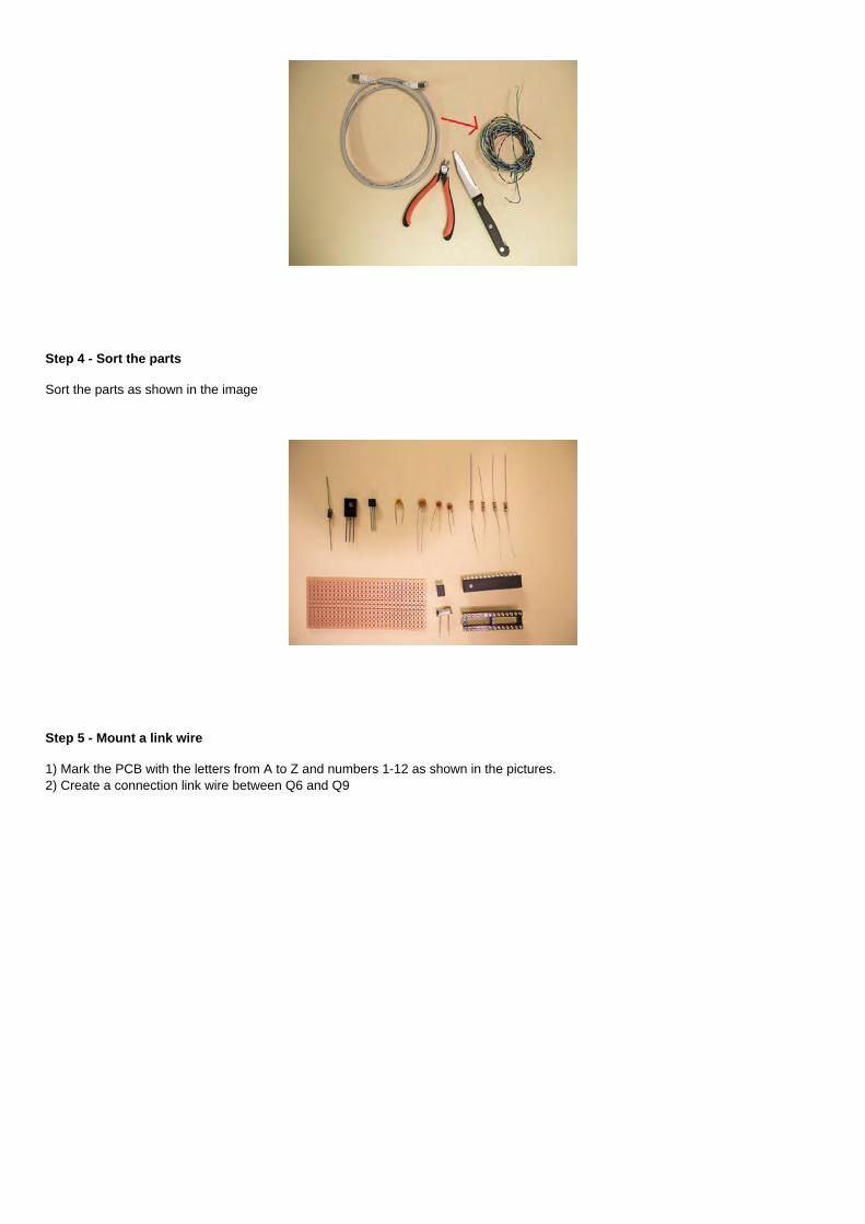
Step 15 - Color codes-Resistors
Color codes of the resistors
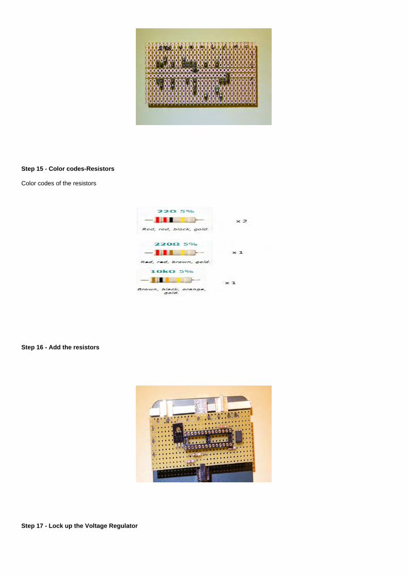
Step 16 - Add the resistors
Step 17 - Lock up the Voltage Regulator

Pinout
Step 18 - Adding Voltage regulator
Add the voltage regulator and make sure it is installed correctly.
Step 19 - Adding link wire #3
This is the link wire #3.

Step 20 - Add diode
Add diode 1N4001. Cathode in hole G10 and anode in hole I10. Make sure it is installed correctly.
Step 21 - Add capacitor 330nF
Add capacitor 330nF from hole F10 to G11This is not polarity sensitive

Step 22 - Add capacitor 10nF
Connect the capacitor from hole E10 to hole F11.This is not polarity sensitive
Step 23 - Add capacitor 22pF x2
Add two 22pF capacitors. One between R11 and S11 and the next between R12 and T12. Push them all the way into the PCB.
Step 24 - Add the Crystal
It must be placed with care from S10 to T11. The crystal should not touch the capacitors nor the IC.

Step 25 - Last Check
Solder all the connections.
Step 26 - Adding link wire #4
Step 27 - Adding link wire #5
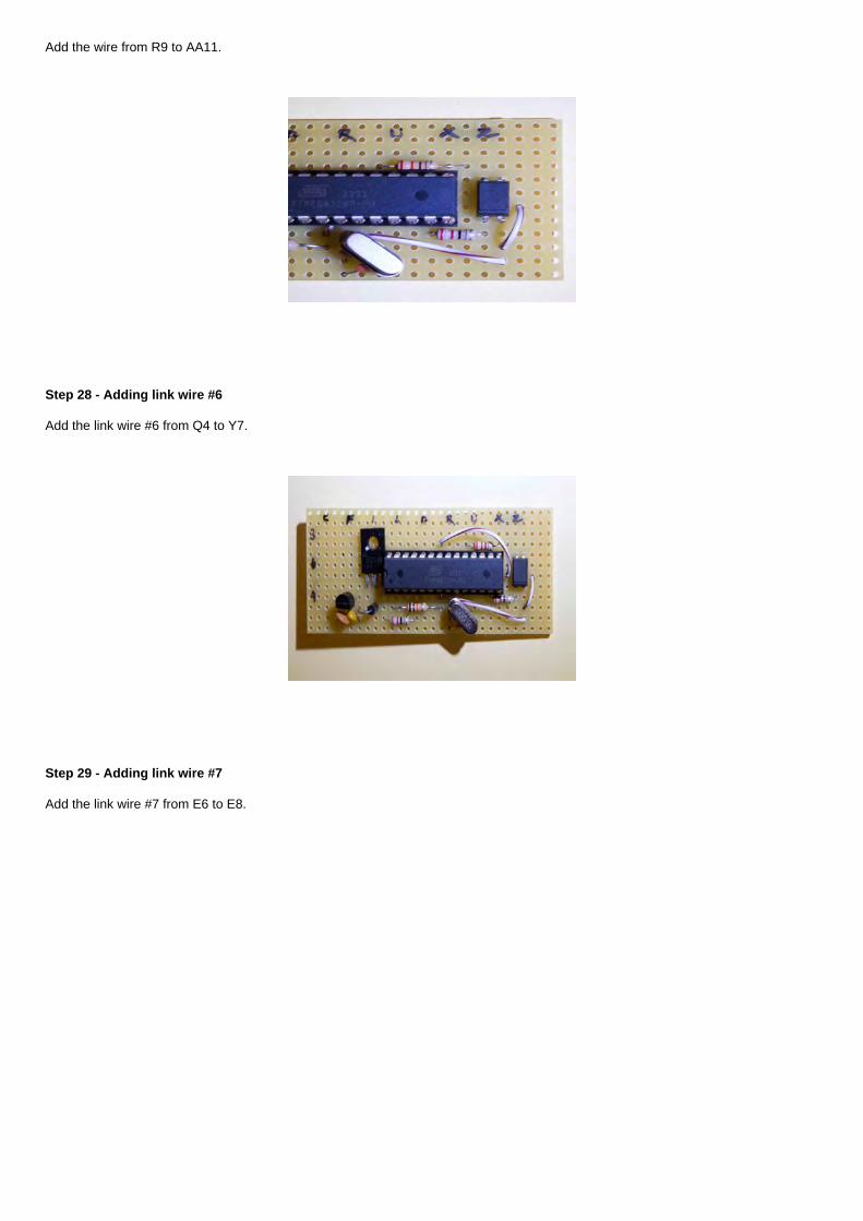
Add the wire from R9 to AA11.
Step 28 - Adding link wire #6
Add the link wire #6 from Q4 to Y7.
Step 29 - Adding link wire #7
Add the link wire #7 from E6 to E8.

Step 30 - Adding link wire #8
Add the link wire #8 from Q5 to Q6.
Step 31 - Adding the Solenoid valve
Add wiring for the Solenoid valve.
Step 32 - Adding the flash

Add wiring for the flash between Z4 and AA4.
Step 33 - Adding the power plug and power switch
Fit a plug on the battery box. Use the multimeter to check that you get 12 V reading. Install a switch in series with GND conductor(blue color). Negative leader engaged through holes G7 and turn OFF the power switch.Connect the positive conductor (blue/White color) to hole G8 and mount the positive lead (blue / white) directly to the hole G8.
Step 34 - Add the LED light
The long leg is the positive pole and the short is the negative pole. Use green color at the negative pole and connect it to E7. Usewhite/green color at the positive pole and connect it to Y3.

Step 35 - Add the RCA plug for the Solenoid valve
Add the RCA plug for the solenoid valve.The brown cable is already connected to the board.
Step 36 - Make a RCA cable for the valve
Make a RCA cable for the valve. Polarity is not important.

Step 37 - A last very check
Step 38 - Testing the system
Turn the power switch ON.
The LED will light up in the first 10 seconds, then turn off the lamp in 8 seconds.
Then the light will blink twice, solenoid valve activates and the flash light on the transmitter will flash once. Pause for 5 seconds.
Then the light will blink twice, solenoid valve activates and the flash light on the transmitter will flash once. Pause for 5 seconds.
If not, something is wrong!
Is the voltage regulator or IC circuit is hot? If it is hot, turn off the switch.
Step 39 - Boxing the project
Once you have tested that the flashing of LED and flash receiver and activation of solenoid valve, you are ready to put the toys into abox. You need a drill and a 8mm and 13mm wood drill.

Step 40 - Drilling hole for the switch and the LED light
Step 41 - Drill holes for the power jack and the solenoid valve
.
Step 42 - The box is just big enough, but not more than that.

The box is just big enough, but not more than that.
Step 43 - OPTIONAL (you can use something else that stand)
Lengths2 piece of 560mm (22")5 piece of 365mm (15")2 piece of 270mm (11")6 piece of small corners
You can also make two longitudinal grooves on the two longest sticks. These traces can be used to fasten the back wall to the rig
Step 44 - First we glue a stand base
It's nice to have an angle. Glue first two sticks together, use the angle, then wait 15 minutes before pasting pins 3 and 4.Let dry before you glue the small wood angles (that later will support larger the cross-pin's)

Step 45 - Then we glue the stand to hold the solenoid valve.
Take it easy. Leave the first pegs to dry for 10-15 minutes before proceeding
Step 46 - We need a bag container for solenoid valve
Note: It's advisable to drill the hole to the valve first and then wash away all the plastic shavings. This is because the solenoid valvecan be damaged if filled with plastic pieces.
Finally glue the valve to the pipe

Step 47 - Glue the valve to the pipe
Use a piece of tape to hold the share while the glue dries. Glue first on one side of the valve, let dry, and then the other side
Step 48 - Completed rig
Note that the background is attached to the longitudinal grooves in the rack. This is a clever detail. The background is often replacedafter a few rounds (also get to get other color combinations)

Step 49 - Now you can take pictures
Preparation of the rig• Prepare three-stand and make sure it stands firmly on a table. Feel free under a towel as it may be a little mess.• Attach the solenoid valve to the mounting brackets on the rack• It is very important that the stand is not skewed (because that would not drop the second landing on the same space as thedroplet number one).• Fill the roasting pan with 1.8 liters of water and 2dl milk. • Mix the three drops of food coloring to 1 cup cold water and add to the container for solenoid valve. Use a funnel so you do notspill• Use a tomstokk to find the right height between the surface and the nozzle to the solenoid valve. Start with a height of exactly38.5 cm. (Later you can test with 36, 37, 39.5 and 40.5 cm - it will give some other characters, but not as many hits).• Install a wall of cardboard. This should be a light color as the back wall also reflects the light from the flash. Backboard shouldsurround straw as much as possible because everything around the droplet will be reflected in the droplet shape.
Step 50 - Preparing the camera
Preparation of the flash• Also set the flash in manual mode. Find the adjustment for the flash power output and set it on 1/32. How flash is angled relativeto the subject (drop shape), the surface of the pan and the reflector (background) is very important. The flash can either stand on astand, or it can hang over the edge of the droplet rig.• To trigger the flash then you use a wireless flash receiver. It must be turned ON and channel selectors should both drawn to theedge of the box (the red small buttons).• If the flash has a zoom feature, so set it like in the 105mm to get a more focused beam of light.
Step 51 - Turn on the drip machine
• If pictures are too dark, then you need to change the angle of the flash or the background. Does not help, then you can change

the aperture to F = 16 or increase the ISO value to ISO = 800 or increase the flash power output to 1/16.• If pictures are too light, so you can change the aperture to F = 25, reduce ISO value to ISO = 200 or mute the flash power outputto 1/64.• Start drop the computer.• When the machine has run through 1/3 of the program (after 30sekvenser), so it will take a break at ca. 50 seconds. This is sothat you can replace the water in the pan. It will run after this additional 30 32 sequences, ie a total of 92 before it starts again.• The second round will not be exactly the same characters as in round one. This is because it is now a lower water level in thewater tank of the solenoid valve (lower pressure), more water into the pan and the temperature of the water can be changed.Moreover it will be a certain degree of randomness in the image, and drop number two will rarely fall precisely on top of the dropnumber one. You will thus reveal different characters running sequence several time.• When you are done playing you should run through with clean and warm water before packing.
Step 52 - Troubleshooting
• Unless the flash triggers, but the blue button flashes (and solenoid valve job), then you need to check if a little light on thewireless receiver for the flash strobes. If it blinks then the receiver OK. Then it's probably the batteries for the flash is empty. You candouble check to enable test button on the flash. But if the light on the radio receiver does not flash, check first that it is on. Replaceany batteries in the radio receiver (2 x AAA). Note: The channel selector on the receiver will not change. Both DIP switches must be inthe ON position.• If everything works, but you do not get the picture of some characters, then you must check the distance between the nozzlesolenoid valve and the water surface. Set it to 385 millimeters. Because you still do not forward any figures, so it might be thesolenoid valve that is not 100% vertical. Try to twist the pipe solenoid valve slightly to the right (or left). Does not help, then try to tilt itup or down. This can best be done by adding moe throughout drop rig, either in the back or front.• Another reason why you do not see some characters may be using a bag with another toughness than the usual cold water. Thisprevents timing vote. Possibly it can then help with slightly higher or slightly lower drop height (if you have not had too muchthickener).• If the camera does not want to eject, then it may be that you have not turned the switch on the lens to MF (manual focus).• If you get stripes, tails or blurred edges of the drops, then it may be that you have too much light in the room. Pull the curtains,and then try again.

Step 53 - Creative variants
• Test with different colors on the bags and the background• Test to let drop falling into a cup (as you should check the height of fall over and drop should land exactly in the middle of thecup)• Test different drop heights (for example 36, 37, 39.5 and 40.5 cm).• Test out different pressure on the droplet (the tube for the water tank can be extended by attaching an empty cartridge from anacrylic / adhesive spray)• Test with another nozzle (attached at the tip of the existing nozzle)• Test with another solenoid valve. It must be of the type and 12VDC with a maximum current draw of 500mA• Replace the reflective rear panel with a semi-transparent wall of frozen glass / acrylic. Shoot as the light from the back of theplate (above) with an angle of 45 degrees.• Test with an intermediate ring of 20-36mm between camera and lens. When you come closer.• Let the drop fall in a colored glass bowl (and right flash against the bowl)• Let the drop fall in a low cup and blow a soap bubble on top of the cup. Double check that the height still is 385 millimeters.• Hang a large poster (upside down) on the back of the droplet and let poster motif reflected in straw• Try using colored plastic (gel) in front of the flash• Try to center the flash beam to attach a cardboard tube or something so that the flash beam is very centered.


![Give Me a Home Among the Gum Trees€¦ · For a [G7] little bush [G7] retreat Where the [G7] kooka [G7] burras [] call Give me a [Am] home among the [G7] gum trees [G7] With lots](https://img.pdfslide.us/doc/110x75/5ebee417342d4564823d158c/give-me-a-home-among-the-gum-trees-for-a-g7-little-bush-g7-retreat-where-the.jpg)