Embed Size (px)
Citation preview

Drop and Impact of Mobile Drop and Impact of Mobile TelephoneTelephone
Jason MarenoSr. Applications EngineerMallett Technology, Inc.
Research Triangle Park, NC
Analysis GoalsAnalysis Goals
• Survive everyday drops– Routine drops from 0.5 to 1.7 meters– Various Impact orientations
• Design Cycle – Time is Critical!– Typical product life cycle of only 12 months– Each week late corresponds to enormous loss– Balance risk and reward
• Develop a technique that can provide accurate predictive data in a timeframe consistent with the needs of the rapid development cycle.
Analytical ChallengesAnalytical Challenges
• Complex assembly of many components– Component interaction: rigid links,
constraints, contact, etc…– Small, intricate, and delicate components;
accurate yet efficient mesh is required– Large deflections and many contact
interfaces; nonlinearities abound
• Develop a technique that can provide accurate predictive data in a timeframe consistent with the needs of the development cycle.
Failure ModesFailure Modes• Majority of failures occur when one
component moves/deforms further than anticipated and unexpectedly collides into another component – Exterior housing deflects so far that it crushes
a delicate antenna contact– Protective frame around LCD transmits
significant forces to glass display– Circuit board deflects so far that solder joints
are cracked• Highly accurate stress calculations not
required; only an accurate representation of deformed shape versus time
Analytical GoalAnalytical Goal
• Quickly and accurately predict component interaction and deflection.
• Global model must quickly predict "what will hit what" and "how far things will bend"
• If needed, use submodels to calculate stresses as necessary.
• The mesh must represent stiffness accurately, and stresses approximately.
Time Integration SchemeTime Integration Scheme
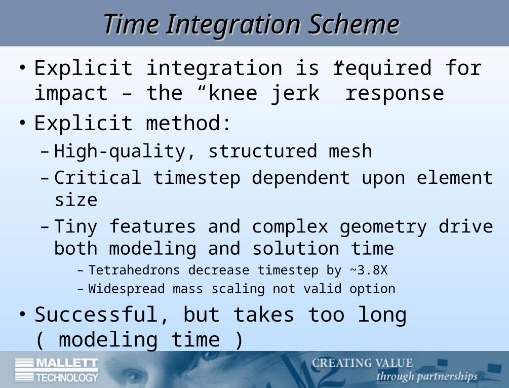
• Explicit integration is required for impact – the “knee jerk” response
• Explicit method:– High-quality, structured mesh– Critical timestep dependent upon element
size– Tiny features and complex geometry drive
both modeling and solution time– Tetrahedrons decrease timestep by ~3.8X– Widespread mass scaling not valid option
• Successful, but takes too long ( modeling time )
Time Integration SchemeTime Integration Scheme
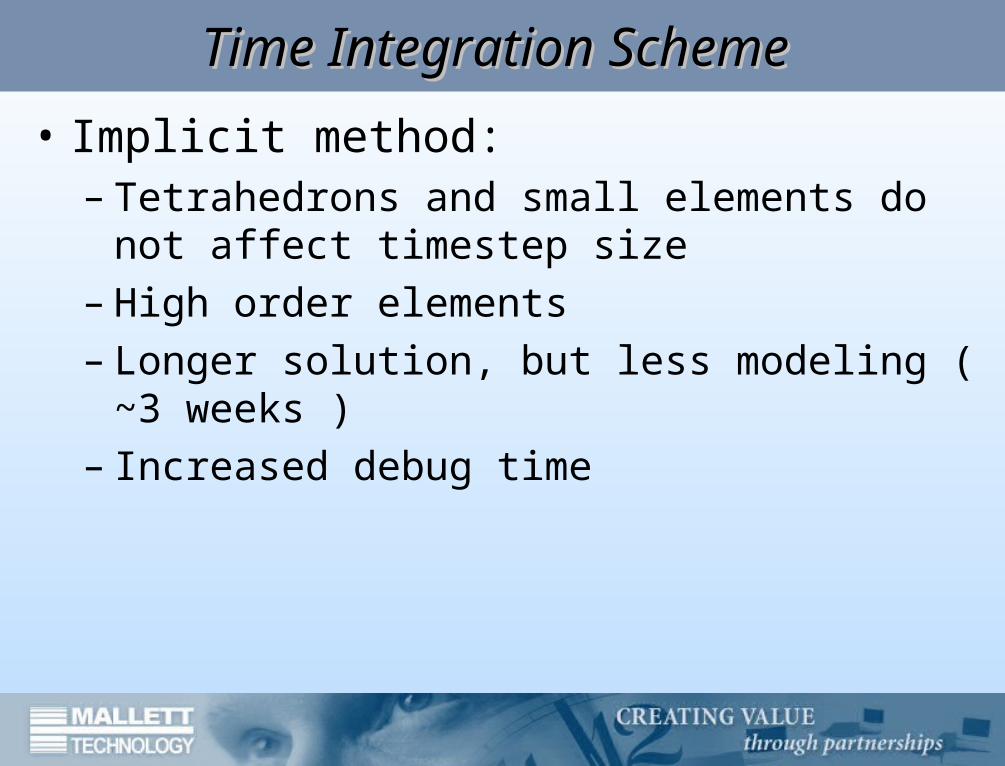
• Implicit method:– Tetrahedrons and small elements do not
affect timestep size– High order elements– Longer solution, but less modeling ( ~3
weeks )– Increased debug time
Problem DescriptionProblem Description
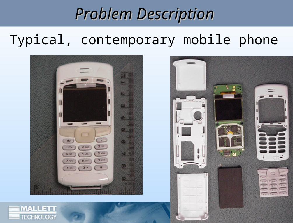
Typical, contemporary mobile phone
Event CharacterizationEvent Characterization• Contemporary phones typically maintain
contact with the floor for two to three milliseconds and resonate with significant amplitude for up to three milliseconds during rebound. Total event duration is estimated at six milliseconds.
• For component-level tests, industry-standard shocks are half-sine, up to 2900 multiples of gravity (G), and as short as 0.3 milliseconds in duration.
• Shock waves on the order of 1.7kHz (0.6 msec period) can be anticipated in the circuit board during an assembly-level drop test.
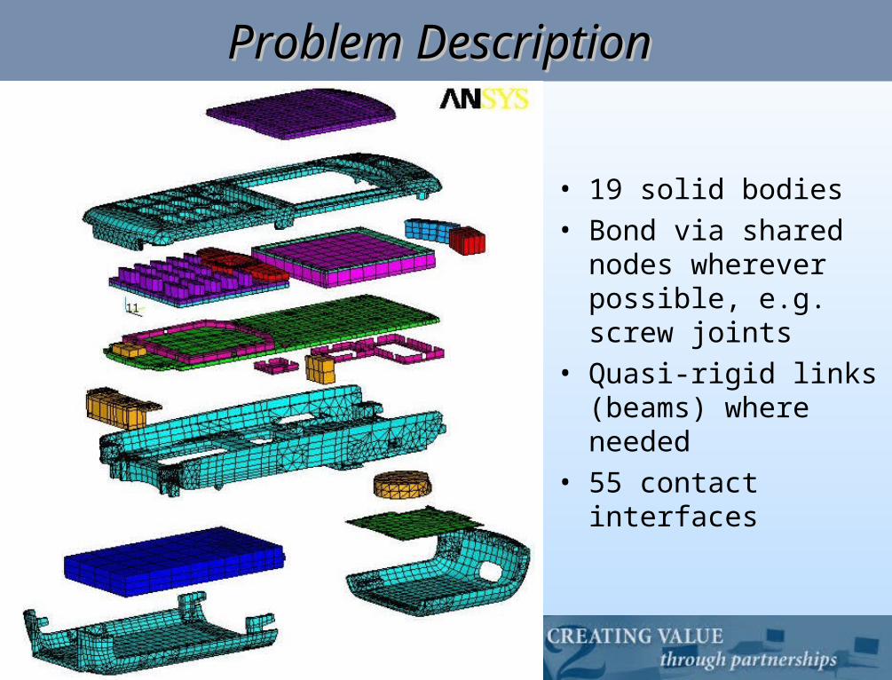
Problem DescriptionProblem Description
• 19 solid bodies• Bond via shared
nodes wherever possible, e.g. screw joints
• Quasi-rigid links (beams) where needed
• 55 contact interfaces
ModelingModeling
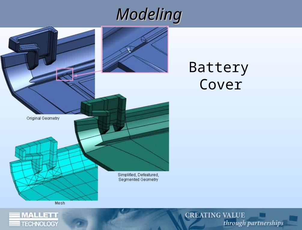
Battery Cover
ModelingModeling
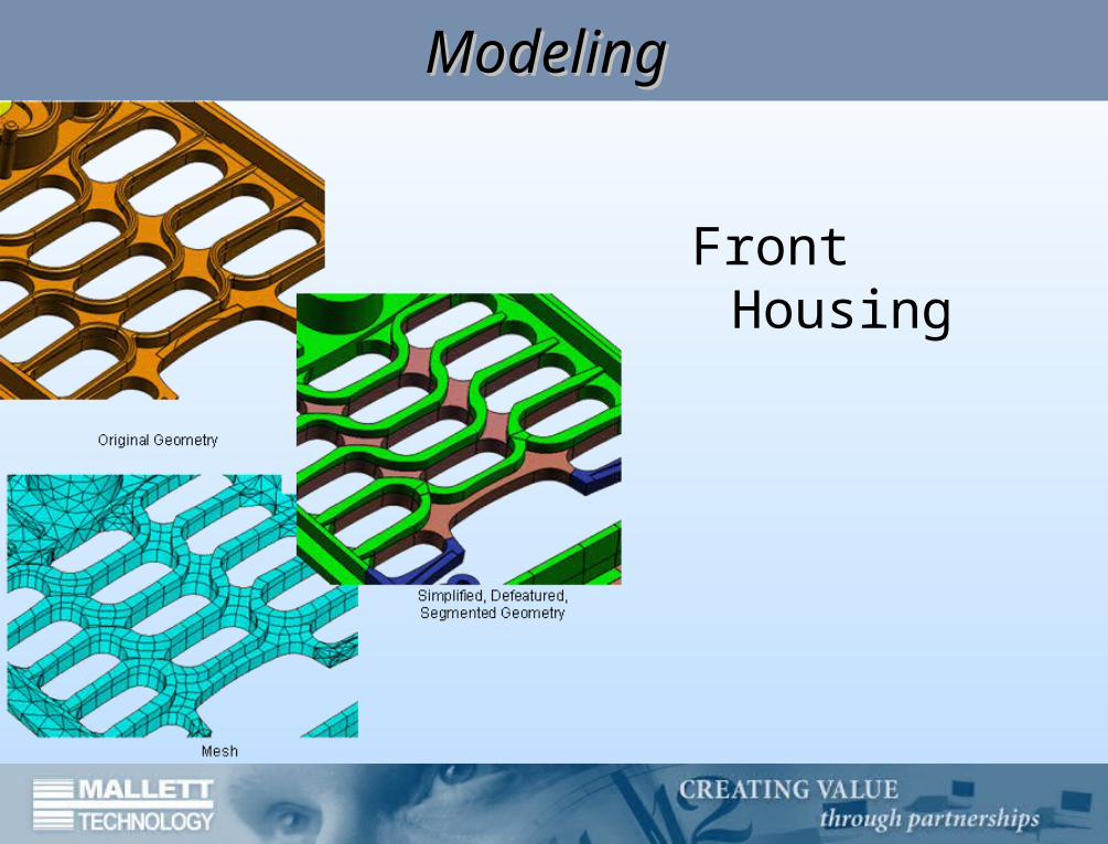
Front Housing
ModelingModeling
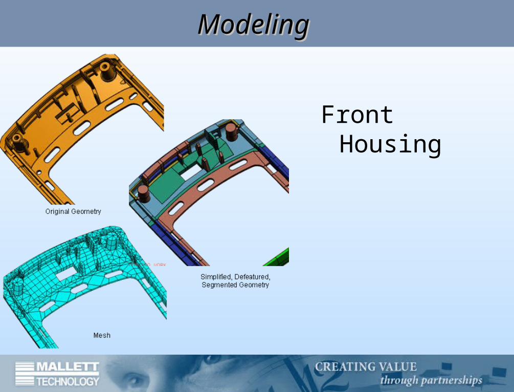
Front Housing
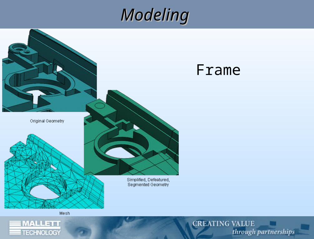
ModelingModeling
Frame
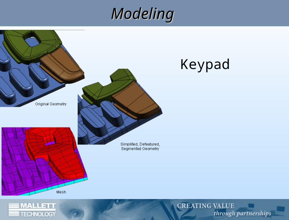
ModelingModeling
Keypad
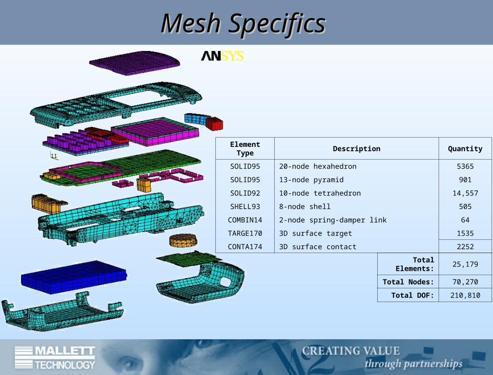
Mesh SpecificsMesh Specifics
Element Type Description Quantity
SOLID95 20-node hexahedron 5365
SOLID95 13-node pyramid 901
SOLID92 10-node tetrahedron 14,557
SHELL93 8-node shell 505
COMBIN14 2-node spring-damper link 64
TARGE170 3D surface target 1535
CONTA174 3D surface contact 2252
Total Elements:
25,179
Total Nodes: 70,270
Total DOF: 210,810

Material PropertiesMaterial Properties
• All materials modeled as linear elastic• Deflection is the primary quantity of interest• No ‘plastic hinges’ expected• Gross deflections not seriously affected by this
assumption
• Rate dependency for thermoplastic resins roughly accounted for
• Stiffness-proportional damping • Material-dependent
• ( Proprietary )
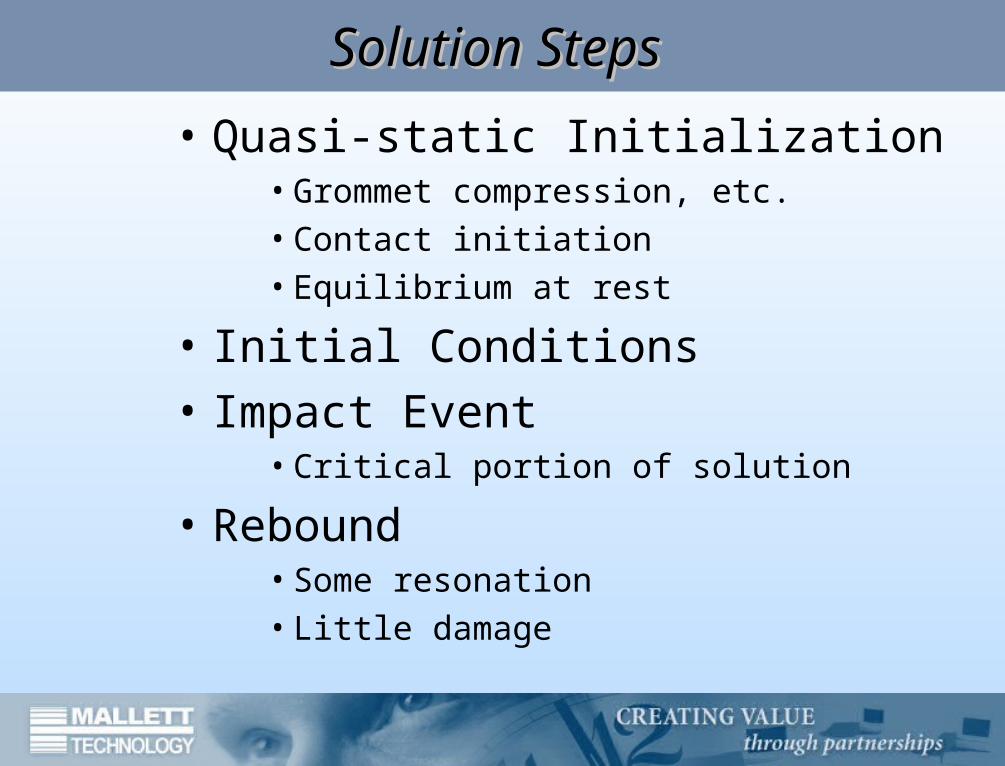
Solution StepsSolution Steps
• Quasi-static Initialization• Grommet compression, etc.• Contact initiation• Equilibrium at rest
• Initial Conditions• Impact Event
• Critical portion of solution
• Rebound• Some resonation• Little damage
Convergence CriteriaConvergence Criteria
• Quasi-static steps controlled by the traditional L2 force residual
• Deflection is the stated goal; impact and rebound steps controlled by L2 displacement norm only
• Fidelity of contact forces/stresses not required• Maximum of 0.03mm contact penetration deemed
acceptable• If highly accurate stress calculations were required, the
convergence criteria would need to be reevaluated. For the stated goal of this analysis, the chosen convergence criteria more than suffice.
025.00025.01000900,209 22
Time StepTime Step• Newmark integration scheme with γ=0.5050
and β=0.2525 (very nearly equal to the trapezoidal integration rule, or average acceleration scheme)
• Automatic timestepping with a maximum timestep of Δt<0.05 milliseconds (corresponds to 20pts/cycle at 1kHz)
• Period error calculated to be less than 1% at 1kHz; amplitude error is identically zero for the average acceleration scheme.
• Rayleigh quotient was monitored. Observed minimum of 40 points per response cycle.
22
1
4
4tan
t
ttErrorPeriod
ResultsResults
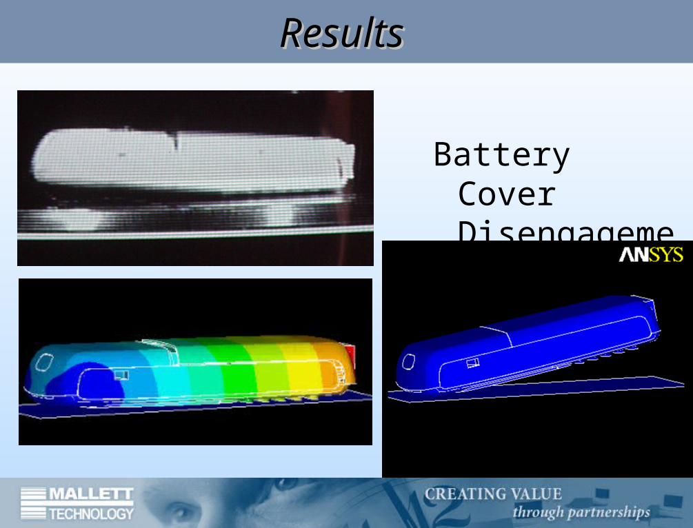
Battery Cover Disengagement
ResultsResults
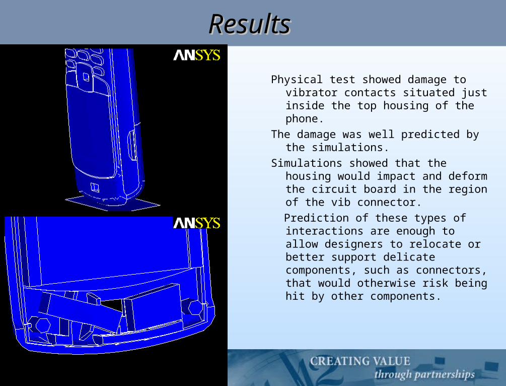
Physical test showed damage to vibrator contacts situated just inside the top housing of the phone.
The damage was well predicted by the simulations.
Simulations showed that the housing would impact and deform the circuit board in the region of the vib connector.
Prediction of these types of interactions are enough to allow designers to relocate or better support delicate components, such as connectors, that would otherwise risk being hit by other components.
NotesNotes
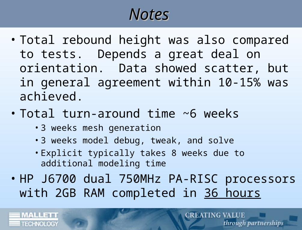
• Total rebound height was also compared to tests. Depends a great deal on orientation. Data showed scatter, but in general agreement within 10-15% was achieved.
• Total turn-around time ~6 weeks• 3 weeks mesh generation• 3 weeks model debug, tweak, and solve• Explicit typically takes 8 weeks due to additional
modeling time
• HP J6700 dual 750MHz PA-RISC processors with 2GB RAM completed in 36 hours
ConclusionsConclusions
Develop a technique that can provide accurate predictive data in a timeframe consistent with the needs of the rapid development cycle
Highly accurate stress calculations not required; only an accurate representation of deformed shape versus time
Implicit method is a valid option