Embed Size (px)
Citation preview

DIGITAL RADIO MONDIALE (DRM)
D
Digital Radio Mondiale is a system which promises to re-invigorate theuse of the broadcasting bands below 30 MHz. It offers a dramaticimprovement in audio quality, not only improving the audio bandwidthand signal-to-noise ratio, but also countering the effects of selectivefading and audible interference from other stations. It is also designed tosupport various features that will make receiver operation more user-friendly.This article describes the basic “mechanics” of DRM and its features,which include station identification, alternative frequency lists andsupport for time-varying frequency schedules – of particular importancein HF broadcasting.
At present, the various broadcasting bands below 30 MHz are used in much the sameway as they always have been since the birth of radio broadcasting over 80 years ago.Audio is conveyed on the radio-frequency carrier in the form of amplitude modulation(AM) 1. In consequence these broadcasting bands are often called the “AM bands” –distinguishing them from the very-high-frequency (VHF) broadcasting band wherefrequency modulation (FM) is used.
The AM bands are very useful to broadcasters because the modes of propagation used(ground and sky wave) give coverage to large or remote areas – the latter being invalu-able for international broadcasting.
As you might suppose for a system with such early beginnings, a very simple receivercan be used. This, together with the fact that most listeners have grown up taking itsexistence for granted, helps to explain the very large number of AM receivers esti-mated to be in use: over 2 billion.
1. To be more precise, the technique used is “double-sideband AM with carrier”.
Jonathan StottBBC Research & Development
RM — key technical features
EBU TECHNICAL REVIEW – March 2001 1 / 24J. Stott

DIGITAL RADIO MONDIALE (DRM)
However, radio listeners are becoming more sophisticated, more discerning and havemore sources of entertainment and information becoming available to them all thetime. Present AM radio cannot match the sound quality of FM radio, let alone CDsand other digitally stored or received formats, so listeners have every incentive todesert AM radio.
So, broadcasting in the “AM bands” must evolve to meet the new circumstances.There are very good reasons to keep these bands for broadcasting purposes because ofthe types of coverage that they, uniquely, can provide. What is needed is a way toimprove the audio quality, and indeed the whole listening experience (ease of use, sup-plementary information, presenting the choices available for easy selection …) – inother words, to be more “listener-friendly”.
The way to achieve this is to apply digital processing tech-niques, just as has been done with other bands and othermedia. This has been done by the efforts of many organiza-tions within the Digital Radio Mondiale (DRM)consortium [1]. The system that they have developed hasalready been recognized by the International Telecommu-nications Union (ITU) in a draft Recommendation [2] fora world standard for digital broadcasting below 30 MHz.
This article describes some of the features and principles ofoperation of the DRM system. But first it is useful to recap what AM does now, andwhat the bands have to offer.
The “AM Bands”
Current uses of the AM bands
The AM bands serve a wide range of purposes, taking advantage of the properties ofthe two modes of propagation at these frequencies: ground wave and sky wave.
The lowest-frequency broadcasting band – LF, often known as the long-wave band(LW) – can provide extended coverage by ground wave from a single transmitter, andis thus very effective for national coverage and beyond. The long wavelength implieslarge transmitting-antenna structures, so this band is normally only used where a largecoverage area is desired and can thereby justify the investment in the antenna. LW ispopular in Europe especially, but is not available for broadcasting in the Americas.
The medium-frequency (MF) or medium-wave (MW) band is available throughout theworld and has a wide range of uses. Ground-wave propagation is slightly less effec-tive at this frequency than at LF, but daytime coverage is still good. One transmitter ora small network of a few transmitters can provide national coverage (depending on thesize of country) although the band is also used for local coverage with a single low-
EBU TECHNICAL REVIEW – March 2001 2 / 24J. Stott

DIGITAL RADIO MONDIALE (DRM)
power transmitter. At night (when absorption in the D layer of the ionosphere isreduced) sky-wave propagation occurs in addition to ground wave. This can be con-sidered a hindrance or a help. The enhanced propagation can bring interference; e.g. adistant co-channel station unheard during the day becomes audible in the backgroundof the wanted station. There can also be self-interference from the sky wave of thewanted station – this arrives later than the ground wave and thus causes interference asa form of multipath, resulting in fading or distorted sound. However, the enhancedpropagation can also be exploited positively for international broadcasting, to placesthat the ground wave cannot reach.
The HF (or short-wave, SW) bands are mostly known for facilitating internationalbroadcasting, using sky wave. Broadcasts can be targeted at distant countries with theadvantage that there is no gatekeeper to obstruct, or other operator to charge for, thedelivery of the service. Signals can even be sent halfway round the world, althoughmost major broadcasters arrange to have transmitters somewhat nearer the target inorder to improve reliability and give more choice of operating times and frequencies.
Abbreviations
AAC (MPEG-2/4) Advanced Audio Coding
AFS Alternative frequency switching
AM Amplitude modulation
BER Bit-error ratio
CD Compact disc
COFDM Coded orthogonal frequency division multiplex
DAB Digital Audio Broadcasting
DC Direct current
DRM Digital Radio Mondiale
DVB Digital Video Broadcasting
DVB-T DVB - Terrestrial
FAC Fast access channel
FFT Fast Fourier transform
FM Frequency modulation
HF High-frequency
ITU International Telecommunication Union
ITU-R ITU - Radiocommunication Sector
LF Low-frequency
LW Long-wave
MF Medium-frequency
MLC Multi-level coding
MPEG Moving Picture Experts Group
MSC Main service channel
MW Medium-wave
NVIS Near-vertical-incidence sky-wave
OFDM Orthogonal frequency-division multiplex
PA Power amplifier
PM Phase modulation
QAM Quadrature amplitude modulation
RDS Radio Data System
RF Radio-frequency
SBR Spectral band replication
SDC Service description channel
SFN Single-frequency network
SSB Single side-band
SW Short-wave
UEP Unequal error protection
EBU TECHNICAL REVIEW – March 2001 3 / 24J. Stott

DIGITAL RADIO MONDIALE (DRM)
The lower-frequency end of the SW band is also used to provide national coverage oftropical or large countries (see Appendices A and B). Both applications rely on sky-wave propagation and thus depend on the state of the ionosphere, which changes daily,yearly and according to the 11-year sunspot cycle – with some random variationsthrown in. For this reason, use of the HF band involves the broadcaster in changes offrequency during the day, and thus in the course of a broadcast unless broadcastinghours are short. In addition, uncertainties in forecasting, together with the fact that alarge target country may require different modes of propagation in order to reach itsvarious parts, mean that the use of two or more frequencies in parallel is common.
What are the pros and cons of the present AM bands?
Advantages
1) Coverage can be national or international, with few transmitting sites needed;
2) International broadcasting is achieved without gatekeepers;
3) Receivers are simple, cheap, readily available and work anywhere.
Disadvantages
1) Audio quality (bandwidth, noise, effects of interference and fading) is limited bymodern standards 2;
2) Frequent changes of frequency (and complicated schedules) in HF broadcastingare confusing for the listener, who may find the receiver difficult to tune;
3) Poor image when compared with more modern digital technologies.
Could things be improved?
The first two advantages above are fundamental to the propagation characteristics ofthe bands themselves. They would therefore be retained whatever the technology –this is why these bands are so important to broadcasters. So, the challenge is to find a
2. In principle, amplitude modulation can support an adequate audio bandwidth. However,pressure on the spectrum means that the channel spacing has been restricted in order toaccommodate more stations. This in turn means that the bandwidth of receivers has beenreduced accordingly – in order to minimize adjacent-channel interference. In parts of the worldwhere the spectrum is less crowded, wider transmitter and receiver bandwidths could inprinciple be used, thereby increasing the received audio bandwidth. The distortion caused bythe selective fading that results from multipath reception can be reduced by using asynchronous detector instead of the common envelope detector. However, the audio signal-to-noise and signal-to-interference ratios remain inextricably linked to the corresponding RF ratios.
EBU TECHNICAL REVIEW – March 2001 4 / 24J. Stott

DIGITAL RADIO MONDIALE (DRM)
way to overcome the disadvantages without losing the essentials of the third advan-tage. Digital technology is the answer.
DRM – the digital alternative
What is DRM?
DRM is a consortium which brings together a wide spread of relevant experience, hav-ing members (see Panels 1 and 2) drawn from broadcasters and transmitter operators,manufacturers of transmitters and receivers, and research organizations. They recog-nized that introducing a new broadcasting system involves more than just developing“clever technology” – it must be the right technology, which solves the real problems.They therefore adopted a structure loosely based on that used by the DVB 3 project,having a Steering Board, Commercial Committee and Technical Committee. TheTechnical Committee is tasked with developing technical solutions to the requirementsidentified by the Commercial Committee.
Sub-groups of the Technical Committee propose and develop the various parts of thesystem. In addition, a System Evaluation sub-group tests what has been developed,both in the laboratory and the field. Field tests have the added and important functionof measuring the characteristics of typical LF/MF/HF broadcasting paths. This pro-vides a level of detail that was not generally available but is essential in order to tailorthe design to match what is needed.
Discussion of some key requirements
The official User Requirements for DRM are set out in a formal document which canbe found on the DRM website [1]. Let us briefly consider some of the key ones (asexpressed in the author’s words).
� The audio quality, as perceived by the listener, must be improved over thatachieved by AM, so that DRM stations can compete with other stations usingFM which may also be available to the listener
The most obvious quality limitation of present AM is the audio bandwidth. Inaddition to this “intrinsic” limitation, AM quality can be impaired by limited sig-nal-to-noise ratio, slow or fast fading, selective fading from multipath, co- andadjacent-channel interference and other interference from man-made and naturalsources. Robustness against all of these is important, in addition to the “intrinsic”quality achievable under good conditions.
3. Digital Video Broadcasting. The DVB project has developed standards (which have been widelyadopted) embracing all aspects of digital video broadcasting, including cable, satellite andterrestrial delivery. See http://www.dvb.org.
EBU TECHNICAL REVIEW – March 2001 5 / 24J. Stott
DIGITAL RADIO MONDIALE (DRM)
Panel 1DRM Members
� Academy of Broadcasting Science of China (China)
� Antenna Hungaria (Hungary)
� Atmel ES 2 (France)
� British Broadcasting Corporation (UK)
� Broadcasting Centre Europe (Luxembourg)
� Coding Technologies Sweden AB (Sweden)
� Comatlas (France)
� Continental Electronics Corporation (USA)
� Deutsche Telekom AG (Germany)
� Deutsche Welle (Germany)
� DeutschlandRadio (Germany)
� Egyptian Radio and TV Union (Egypt)
� Europe 1 (C.E.R.T. – Germany)
� Fraunhofer Institute (Germany)
� Harris Broadcast Corporation (USA)
� International Broadcasting Bureau (USA)
� JVC Victor Company of Japan, Ltd. (Japan)
� Kymenlaakso Polytechnic (Finland)
� LSI Logic Europe (UK)
� Main Centre for Control of Broad-casting Networks, Voice of Russia (Russia)
� Merlin Communications International Ltd. (UK)
� Micronas Intermetall GmbH (Germany)
� NHK Japan Broadcasting Corporation (Japan)
� Norkring AS (Norway)
� Nozema (Netherlands)
� RadioScape Ltd. (UK)
� Radio Canada International (Canada)
� Radio France (France)
� Radio France Internationale (France)
� Radio Nederland Wereldomroep (Netherlands)
� RAI Radio Televisione Italiana (Italy)
� Radio Sweden Intl. (Sweden)
� Retevisión (Spain)
� Riz Transmitters (Croatia)
� Robert Bosch GmbH (Germany)
� Roke Manor Research Ltd (UK)
� Sangean America, Inc. (USA)
� Sony International Europe (Germany)
� SWR Südwestrundfunk (Germany)
� Technisat (Germany)
� Technology for Communications International (USA)
� TéléDiffusion de France (France)
� Telefunken Sendertechnik GmbH (Germany)
� Teracom SE (Sweden)
� Thomcast (France)
� Voice of Nigeria (Nigeria)
This list reflects the membership at the time of writing (January 2001)– please refer to the DRM website for up-to-date information.
EBU TECHNICAL REVIEW – March 2001 6 / 24J. Stott

DIGITAL RADIO MONDIALE (DRM)
� The DRM signal must fit within the present channelling arrangements in theAM bands, but with flexibility to permit exploitation of possible rearrange-ments which may take place during the life of the standard
The changeover from AM to DRM will clearly be a slow process, with so manyexisting transmitters and receivers in place. At the same time, the bands areextremely crowded. So, for changeover to be possible, we must ensure that anyone AM station can be converted to DRM, without upsetting or being disturbed byits existing (geographical and spectrum) AM neighbours. This requirementimplies not only that the RF bandwidth fits the channelling, but also that the pro-tection ratios (AM-DRM, DRM-AM & DRM-DRM) and the necessary carrier-to-noise ratio are compatibly related.
� It should be possible to convert existing modern transmitters to DRMoperation
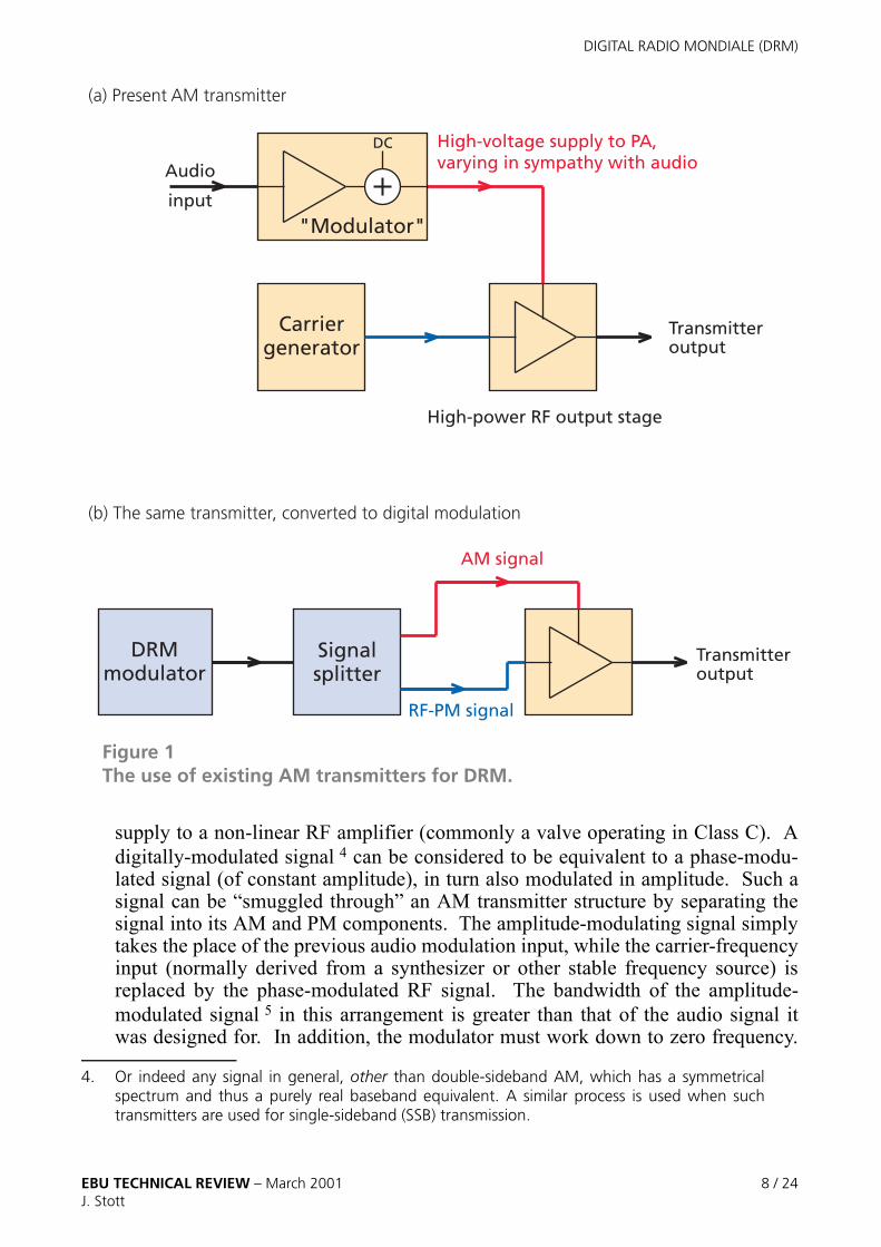
There is a wide range of AM transmitter types in service, some very old indeed. Amajority uses some variety of high-level modulation (see Fig. 1), whereby theamplitude of the RF signal is modulated by varying what is, in effect, the power
Panel 2DRM Associate Members
� Arab States Broadcasting Union (Tunisia)
� Asia Pacific Broadcasting Union (Malaysia)
� CCETT (France)
� Christian Vision (UK)
� Communications Authority Hungary (Hungary)
� DLM Direktorenkonferenz der Landesmedienanstalten (Germany)
� European Broadcasting Union (Switzerland)
� ESPOL (Ecuador)
� Friedrich Ebert Stiftung (Germany)
� HFCC (Czech Republic)
� Institut für Rundfunktechnik (Germany)
� ICRC International Committee of the Red Cross (Switzerland)
� International Telecommunications Union (Switzerland)
� Landesrundfunkanstalt Sachsen-Anhalt /Projektbüro Digitaler Rundfunk (Germany)
� National Association of Shortwave Broadcasters (USA)
� Radio New Zealand International (New Zealand)
� University of Applied Sciences, FH Merseburg (Germany)
� University of Hannover (Germany)� University of Ulm (Germany)
This list reflects the membership at the time of writing (January 2001)– please refer to the DRM website for up-to-date information.
EBU TECHNICAL REVIEW – March 2001 7 / 24J. Stott
DIGITAL RADIO MONDIALE (DRM)
supply to a non-linear RF amplifier (commonly a valve operating in Class C). Adigitally-modulated signal 4 can be considered to be equivalent to a phase-modu-lated signal (of constant amplitude), in turn also modulated in amplitude. Such asignal can be “smuggled through” an AM transmitter structure by separating thesignal into its AM and PM components. The amplitude-modulating signal simplytakes the place of the previous audio modulation input, while the carrier-frequencyinput (normally derived from a synthesizer or other stable frequency source) isreplaced by the phase-modulated RF signal. The bandwidth of the amplitude-modulated signal 5 in this arrangement is greater than that of the audio signal itwas designed for. In addition, the modulator must work down to zero frequency.
4. Or indeed any signal in general, other than double-sideband AM, which has a symmetricalspectrum and thus a purely real baseband equivalent. A similar process is used when suchtransmitters are used for single-sideband (SSB) transmission.
Signalsplitter
AM signal
RF-PM signal
Carriergenerator
DC
"Modulator"
Audio
input
High-power RF output stage
High-voltage supply to PA, varying in sympathy with audio
(a) Present AM transmitter
(b) The same transmitter, converted to digital modulation
DRMmodulator
Transmitteroutput
Transmitteroutput
Figure 1The use of existing AM transmitters for DRM.
EBU TECHNICAL REVIEW – March 2001 8 / 24J. Stott

DIGITAL RADIO MONDIALE (DRM)
In some cases 6 the modulator would have to be replaced to achieve this, while inothers it may sufficient to modify a filter 7.
� The DRM signal should support operation of a single-frequency network(SFN)
SFNs are sometimes used with AM. For LF/MF networks (e.g. for national cover-age) they use spectrum efficiently but at the price of distorted reception in mushareas at the places (between transmitters) where similar strength signals arereceived from two of the transmitters. For this reason, planners try to arrange forthe mush areas to fall in areas of low population – a serious planning constraint.Designing the DRM system to support SFNs would bring the bonus that networkswhich currently use two or more frequencies (because the mush-area problems ofan SFN would be too great with AM) could be converted to SFN operation, inaddition to existing SFNs. There could also be a benefit at HF, where SFNs aresometimes used for international broadcasting with the risk, while using AM, ofmuch of the coverage area becoming a mush area.
� Increased user friendliness
This term encapsulates a wide range of things to improve the listener experience.The listener chooses to listen to a particular station or service, but currently to dothis with AM reception needs detailed knowledge of the band and frequency –which may change with time. The band and frequency are things of no intrinsicinterest – and a DRM receiver should largely insulate the listener from having todeal with them. Suitable data transmitted along with the signal can tell the listener(via display, jingle, speech synthesizer …) what the station is – and tell thereceiver how to find it again, following any scheduled changes in frequency, aswell as advising what alternative frequencies may be available. It is also possibleto give some information about future programmes and their timing. In effect thisis like RDS 8 – updated, expanded and tailored for digital delivery in the AMbands.
5. The bandwidth of the phase-modulated signal is also greater than that of the finally radiatedsignal, but this seems to pose less of a problem in that most transmitters seem to be able tosupport it. Note that limitation in the bandwidth of either path will lead to the transmitterradiating unwanted signals outside its allocated channel bandwidth. For the same reason,delays through the two paths must also be carefully matched.
6. Especially those using a modulation transformer.
7. Modern types of modulator use some kind of switching process (in effect a sampled process)and thus require a low-pass filter. The cut-off frequency of this filter, and perhaps the switchingfrequency itself, has to be increased.
8. Radio Data System – the system used in Europe and beyond to send station identification,alternative frequencies and other data alongside an FM signal.See: http://www.rds.org.uk/rds98/rds98.htm
EBU TECHNICAL REVIEW – March 2001 9 / 24J. Stott

DIGITAL RADIO MONDIALE (DRM)
� Flexibility for the broadcaster to trade intrinsic quality or data capacityagainst ruggedness
A local service provided by ground wave, which happens to have little co- andadjacent-channel interference, may need little protection against errors (and couldthus support a high data rate). By way of contrast, a long-distance sky-wave ser-vice, for example, might have to cope with a large multipath delay spread, interfer-ence and a poor signal-to-noise ratio simultaneously. The broadcaster should beable to exploit the differences and be able to maximize the payload within thecapabilities of the channel 9.
The system developed by DRM takes into account all of these key requirements.
The main processes
A digital sound broadcasting system comprises conceptually distinct transmissionstages.
1) The audio signal must first be converted to digital form. Since the raw bit-rate thatresults is impracticably high, a form of bit-rate reduction tailored to the signalproperties is then applied. This is usually referred to as source coding.
2) The source-coded data is then multiplexed together with any other data that formspart of the payload.
3) The multiplexed data of the payload is subjected to channel coding 9 to increase itsruggedness.
4) The channel-coded data is modulated onto the RF signal for transmission.
Note that source coding reduces the data rate, while channel coding increases it.
At the receiving end, the receiver first acquires synchronization with the signal, thenreverses the transmission stages by means of the following processes:
1) demodulation;2) channel decoding (correcting the transmission errors);3) demultiplexing the transmitted data into component streams;4) source decoding (to obtain an audio signal from the audio stream).
9. It is unfortunate that the word “channel” gets over-worked in RF engineering and this article– in following standard usage – compounds the felony. It can mean (a) the chunk of spectrum(in this case 9 or 10 kHz wide) around the nominal transmission frequency (as in“channelling”), or (b) the combination of all the impairments that the signal suffers along thepath from the transmitter to the receiver (as in “fading channel”, “channel coding”).
EBU TECHNICAL REVIEW – March 2001 10 / 24J. Stott

DIGITAL RADIO MONDIALE (DRM)
AA
CA
ACSBR
SBR
In practice these processes do not separate quite so neatly in every particular case, butthe concept is nevertheless useful. Indeed, a similar division was used to divide thework of DRM development between teams with relevant expertise.
Source Coding
Requirements
The capacity available for audio within a single 9 or 10 kHz channel is distinctly lim-ited – at best in the mid-20s of kbit/s, and perhaps as little as 10 kbit/s for someextremely unfavourable examples of HF paths. This clearly represents a serioussource-coding challenge for DRM, which expects to deliver good audio quality forboth speech and music.
Key technologies
DRM has picked up on work already done in the development of sourcecoding elsewhere and has fine-tuned it to the particular application. Forcoding most broadcast programme material, a “waveform” coder isneeded in order to cope with the arbitrary mix of speech, music and inci-dental background sounds. DRM uses for this purpose Advanced AudioCoding (AAC), supplemented by Spectral Band Replication (SBR).
In principle, an alternative for speech-only programming is to use acoder designed expressly for speech, in which case the bit-rate can be
reduced more than is possible with a waveform coder, while retaining thesame speech quality. Although this could offer broadcasters further flexibility,
there is however some doubt whether this approach would be used much in practice.Even notionally “speech-only” broadcast material contains jingles, background soundsin interviews and so on – all of which cause serious problems to speech coders.
How it works
Waveform coders, like AAC, work by analysing the content of each part of the audiospectrum and describing each no more accurately than is needed in order to satisfy theear of the listener. Sounds that are masked by nearby louder sounds are discarded alto-gether. AAC follows in the tradition of MPEG-1 Layer 2 and MP3 in this regard, andforms part of the MPEG-4 standard.
However, even with the advances made, it is difficult to deliver an “FM-like” 15 kHzbandwidth using AAC alone at the very low bit-rates envisaged, without introducing
EBU TECHNICAL REVIEW – March 2001 11 / 24J. Stott

DIGITAL RADIO MONDIALE (DRM)
SBRBR
AA
C-A
AC-
S
audible artefacts. The results are better if AAC is used to deliver a more mod-est bandwidth – but this would mean that we fail in one of our key objectives:a noticeable increase in audio bandwidth compared with AM.
The answer lies in the combination of AAC with the SBR technique.
The SBR technique synthesizes the sounds which fall within the highestfrequency octave-and-a-bit. Sounds in this range are usually either:a) noise-like (sibilance, percussion instruments such as shakers,
brushed cymbals etc.), orb) periodic and related to what appears lower in the spectrum (over-
tones of instruments or voiced sounds).
At the sender, the highest-frequency band of the audio signal is exam-ined to determine the spectral distribution and whether it falls into cate-gory (a) or (b) above. A small amount of side information is thenprepared for transmission to help the decoder. The highest-frequencyband is then removed before the remaining main band of the audiosignal is passed to the AAC coder, which codes it in the conventionalway.
At the receiver, the AAC decoder first decodes the main band ofthe audio signal. The SBR decoder then adds the synthetic upperband, helped by the instructions sent in the side information. Over-tones are derived from the output of the AAC decoder, while noise-likesounds are synthesized using a noise generator with suitable spectral shaping.
The possibility of stereo operation is foreseen, although this would only be sensiblewhere it was possible to use a double-width channel of 18 or 20 kHz RF bandwidth.
Multiplexing
With the limited bit-rate available, it is important to strike the right balance betweenflexibility and efficiency while protecting each bit of information to an appropriatedegree. A distinction is therefore made between main payload data and the varioustypes of data that the receiver needs to help it find and decode the desired programme.Furthermore, an option is provided for unequal error protection (UEP) of the payloaddata itself, so that the greatest protection is given to the data whose corruption wouldcause the worst impact on the audio signal.
The main payload is called the Main Service Channel (MSC). Two subsidiary chan-nels are also provided, namely the Fast Access Channel (FAC) and the ServiceDescription Channel (SDC). These two are key to ensuring a simplicity of operation
EBU TECHNICAL REVIEW – March 2001 12 / 24J. Stott

DIGITAL RADIO MONDIALE (DRM)
of the receiver and are therefore designed to be reliably received in adverse conditions,with different forward error-correction from the MSC.
The FAC is intended to be decoded quickly by the receiver on first acquiring the signal(at switch-on, or during scanning). It carries a minimum of constantly-repeated datawhich might be essential at this stage, informing the receiver what bandwidth option isin use, what modulation is used for the SDC and MSC, which length of interleaver isused for the MSC, etc.
The SDC contains more data, also sent repeatedly but in a longer cycle so as to main-tain efficiency. It contains an identification of the service(s) available in the MSC,together with further information to instruct the receiver how to decode each service.It is here that lists of alternative frequencies and frequency schedules would be trans-mitted if appropriate.
Finally, the bulk of the signal conveys the MSC. With the limited bit-rate availablewithin one 9 or 10 kHz channel, this would normally be used to carry one audio pro-gramme, together with a modicum of data. Nevertheless, there is a degree of flexibil-ity, so the MSC may contain between one and four streams of data. Streams andservices are distinguished as follows. An audio service consists of one stream carryingaudio, and optionally one stream carrying data. A data service consists of one streamcarrying data.
Channel coding and modulation
Key technologies
Once sky-wave propagation or an SFN is involved, there is a clear need to be able tocope with multipath propagation. The delay spread can be as much as many millisec-onds. This is long in comparison with (1/bandwidth), which makes DRM anotherapplication, following DAB and DVB-T, for which the multi-carrier modulationknown as COFDM is appropriate 10. Care is nevertheless needed as in some situationsDoppler spread is also high, making DRM in some ways a more difficult applicationthan DAB or DVB-T.
The C of COFDM stands for the essential forward error-correction Coding. Theredundancy this provides enables the receiver to cope with both noise and the effectsof fading and other channel impairments. The coding is based, like DAB and DVB-T,on the use of a convolutional code, but in a slightly more elaborate arrangement calledMulti-Level Coding (MLC).
10. A single-carrier modulation system would require that the receiver had an adaptive equalizerwith a large number of taps. The larger this number of taps, the more favourable thecomparison becomes to COFDM, in terms of complexity and feasibility.
EBU TECHNICAL REVIEW – March 2001 13 / 24J. Stott

DIGITAL RADIO MONDIALE (DRM)
M
COFDCO
FDM
Since nearly-flat fading can occur in this application, as well as frequency-selectivefading, both time and frequency interleaving are used.
COFDM
COFDM should by now be well known from its use in DAB and DVB-T.For a fuller explanation of the basic principles, please see an earlier articleby the author [3]. The data to be transmitted are coded, using a convolu-tional forward error-correcting code, and distributed over a number of car-riers for modulation and transmission. Each carrier thus has only arelatively small bit-rate to convey. This makes it possible to ensure thatmultipath spread is small compared with symbol length, so that, with theaddition of a small guard interval, inter-symbol interference in the pres-ence of multipath can be eliminated.
Furthermore, the carriers are arranged to be spaced in frequency by thereciprocal of the length in time of the window in which the receivertakes a “snapshot” of the waveform corresponding to each symbol –this ensures absence of crosstalk between carriers (in the absence ofDoppler spread). (This is known as the orthogonality criterion).
The process of modulating and demodulating the many carriers isachieved far more easily than it is described, using a Fast FourierTransform (FFT).
COFDM is resistant to common transmission impairments. Forexample, if one carrier is severely attenuated by selective fading,the receiver can note this and flag the coded data bits that are demodu-lated from it as being potentially of low reliability. The error-correcting decoder canthen take this channel-state information into account in the decoding process. Simi-larly, provided there is sufficient interleaving, a similar approach could be taken whenall carriers in a symbol are disturbed by a brief flat fade or impulsive disturbance.
Reference cells (like the “scattered pilots” of DVB-T) are inserted so that the channelresponse can be measured, and some further reference cells are provided to aid syn-chronization.
Flexibility
The advantages of COFDM can only be obtained if its parameters (carrier spacing,guard-interval length) are appropriately chosen to match the channel impairments. Ifthe guard interval is too short, then performance will be lost because of the inter-sym-bol interference; conversely, for it to be too long is wasteful as the data capacity is less
EBU TECHNICAL REVIEW – March 2001 14 / 24J. Stott

DIGITAL RADIO MONDIALE (DRM)
than it could be. If the carrier spacing is too small, then the ability to withstand Dop-pler spread will be insufficient.
Considering the wide range of broadcasting uses to which the LF, MF & HF bands areput, and the different propagation modes, DRM provides a range of “OFDM parametersets” (carrier spacing / guard-interval combinations) so that broadcasters have the flex-ibility to adapt to their circumstances while maximizing capacity. The code rate andconstellation type (16-QAM or 64-QAM for the MSC) can also be chosen as part ofthe capacity/ruggedness trade-off.
Two of the OFDM parameter sets are expected to cover most applications. One has aguard interval of 2 ms, together with a carrier spacing of 41 Hz. This is described asintended for “Gaussian channels, with minor fading”, and is thus particularly suitablefor local or national coverage at LF/MF, although it may also be useful in some longer-distance applications. The guard interval is sufficient for SFN operation.
Another parameter set is described as intended for “Time and frequency selectivechannels, with longer delay spread”. It has a guard interval of 5 ms, with a carrierspacing of 46 Hz and a higher density of pilots. The longer guard-interval copes withgreater multipath spread, as can be caused during multi-mode, multi-hop sky-wavepropagation, while the greater carrier spacing and pilot density give greater toleranceto Doppler spread.
It will now be clear why measurements of delay spread and Doppler spread have beenmade during DRM field trials.
For each parameter set, a total number of carriers is specified to make the whole signaloccupy just less than the nominal bandwidth available. There are bandwidth optionscorresponding to a normal channel, a double channel and one-half channel. As both 9and 10 kHz channelling exists in the world (see Appendix A), this makes six nominalbandwidths in all: 4.5, 5, 9, 10, 18 & 20 kHz.
Where the data streams go
The FAC and SDC are fitted into the signal in ways that support their functionality (seeFig. 2).
As the FAC tells the receiver which bandwidth option is in use, it follows that the FACmust be confined within 4.5 kHz, whatever the bandwidth option in use, so that thereceiver can find it. The same subset of the spectrum also contains certain synchroni-zation references for the same reason.
There is also a division in time. A transmission superframe is 1.2 s long and is dividedinto three transmission frames of 400 ms, each containing a whole number of OFDMsymbols.
23--- 2
3---
13---
78---
EBU TECHNICAL REVIEW – March 2001 15 / 24J. Stott

DIGITAL RADIO MONDIALE (DRM)
The pattern of reference cells continues throughout; however, data cells are treatedslightly differently. Symbols at the beginning of each transmission superframe areused to carry the SDC alone, while all the other symbols are used to carry the MSC andFAC. This time-division arrangement is intended to facilitate alternative-frequencyswitching (AFS) in simple receivers.
The SDC contains only data that is sent repeatedly. Once the receiver has all thisinformation, it does not need to decode the SDC data in every transmission super-frame. This means that there is the opportunity (every 1.2 s) for a receiver which has asingle front end to “take a look” at what is happening on another frequency, returningto the main frequency in time to continue receiving the MSC without losing any data.
Various strategies are open to the receiver designer as to what is meant by “taking alook”. At a minimum, the receiver could determine whether a signal is present, andestimate its strength. However, it would be preferable to:
� confirm that the signal found on the alternative frequency carries the same serv-ice as the first (if this is the case, both signals will carry the same SDC andhence have the same emitted waveform);
4.5
kHz
4.5
kHz
Transmission superframe
Transmission frame
SDC MSC & FAC
Time
freq
uen
cy
SDC
MSC & FAC
MSC only
10 k
Hz
Figure 2DRM frame structure, with two bandwidth options, showing that the FAC information is always to be found in the same part of the spectrum, and that the SDC is periodically inserted.
EBU TECHNICAL REVIEW – March 2001 16 / 24J. Stott

DIGITAL RADIO MONDIALE (DRM)
� estimate the quality of reception;
� approximately determine the relative synchronization.
In this way the receiver can decide whether the signal available on the alternative fre-quency is worth switching to, and do so at the next opportunity.
Multi-level coding
DRM, like DVB-T, modulates the MSC data onto the many OFDM carriers using aQAM constellation (either 16-QAM or 64-QAM). Several coded bits are carried byeach constellation. Both DRM & DVB-T also have “hierarchical” modes, which thisarticle will not discuss further – the following applies to “normal” modes only.
DVB-T uses Gray coding of the constellation points 11 (see Fig. 3). All the bits used todetermine which point is sent for each data cell are taken from the same coded data
11. The Gray coding reduces the likelihood of hard-decision errors occurring simultaneously inmore than one bit.
0
0
1
1
0
1
0
1
0
1
1
00 00 11 11 0
0
0
1
10 01 00 11 1
This diagram follows the differing bit-order notationused in DVB-T and DRM documentation.
The bits shown in red and cyan are MSBs for DVB-T and LSBs for DRM.
DVB-T (Gray) DRM
1000
1100 1111
1100 00000000
Figure 3Comparison of mapping applied to a 16-QAM constellation in DVB-T and DRM.
EBU TECHNICAL REVIEW – March 2001 17 / 24J. Stott

DIGITAL RADIO MONDIALE (DRM)
stream and thus have the same degree of protection from the coding. However, thenature of the mapping is such that the bits are not equally robustly conveyed – a codedLSB 12 is more likely to be wrongly interpreted than a coded MSB. This imbalance isnot as bad as it sounds, because what is fed to the Viterbi decoder is not a hard decision(0 or 1) but instead a soft decision, in which the likely reliability is described. Onaverage, MSBs will have soft-decision values indicating greater certainty than LSBs.The Viterbi decoder takes all this into account during decoding. Nevertheless, anotherapproach is possible.
12. Here I mention only LSBs and MSBs, as arise in 16-QAM, which maps two bits-per-axis. Theargument is similar for the three bits-per-axis of 64-QAM. Note also that I use LSB, MSB to referto bits (some authors use LSb, etc, reserving “B” for byte).
Initially, the receiver has no knowledge which of the four states has been transmitted:
The receiver first decodes the LSBs from all the data cells in a coded block. Once this is done, it knows (within the level of reliability given by the strong coding applied to the LSBs) which LSB was sent for each constellation, simplifying the choice for the MSB:
if the LSB was decoded as 1if the LSB was decoded as 0
In deciding whether a 0 or 1 was transmitted for the MSB, the receiver now only has to distinguish between 2 more-widely spaced possibilities, which should be within the capability of the weaker coding applied to the MSBs.
The process can be repeated in further iterations: knowing the MSBs, the LSBs can be decoded again, and so on.
Similarly, for 64-QAM, the three levels LSB, CSB and MSB are successively decoded.
0 01 00 11 1
0 01 00 11 10 01 00 11 1
Figure 4Steps in multi-level coding (one axis only shown).
EBU TECHNICAL REVIEW – March 2001 18 / 24J. Stott

DIGITAL RADIO MONDIALE (DRM)
The alternative is multi-level coding. In this case, the differing frailty of constellationLSBs and MSBs is taken into account by taking them from two streams that have beencoded using different code rates. The MSBs are coded at a higher rate – i.e. lessstrongly coded – in recognition that the receiver is less likely to get them wrong.
In principle this would give an improvement in efficiency – more capacity in bit/s forthe same bit-error ratio (BER) at the same signal-to-noise ratio – on its own. However,provided that the mapping is appropriately chosen, a further refinement can be invokedin the receiver. For simplicity, 16-QAM will be taken in the following explanation,which is an example of the approach that can be followed, once this kind of mappingand separate coding is adopted.
The receiver first decodes the coded LSBs from the constellations of a block ofreceived data cells. This gives the corresponding (smaller) stream of data originallysent (these bits were strongly coded, remember). The stream can then be re-encoded 13, so that on re-visiting the same received constellation points, the receiverknows (to a certain reliability) which LSBs were mapped onto them. This simplifiesthe decision as to which MSB must have been sent (see Fig. 4). In effect the distancebetween a 0 and a 1 for the MSB has been increased, and decoding thus made morereliable.
It is possible to perform multiple iterations of this decoding process, in each case usingthe recently decoded results to improve the reliability of the next step of decoding. Indoing this a modest performance benefit can be obtained.
Interleaving
For simplicity, the explanation just given of Multi-Level Coding neglected any men-tion of interleaving. Most systems using forward error-correction coding need inter-leaving – although the error-correction decoder can cope with a significant proportionof bits being corrupted, it would be overwhelmed if the corrupted bits came in a grouptogether. Certain probable propagation effects have the potential to cause this kind ofdifficulty: selective fades can consistently degrade groups of nearby carriers, while aflat fade can degrade all the carriers simultaneously in one OFDM symbol. For thisreason DRM applies both time and frequency interleaving. The main interleaving isdone on a cell-wise basis, using a convolutional structure in order to minimize the totalthrough delay. Two lengths of time interleaver are provided, so that a broadcasterexpecting stable propagation conditions (e.g. an MF ground-wave service) can offerthe listeners a shorter delay before hearing the programme after switching on, orselecting a different service. Taking account also of the fact that audio data is groupedinto frames, the fundamental through delay (sender and receiver) is of the order of 0.8or 2.4 s for the short or long interleaving options respectively.
13. Various de-interleaving and re-interleaving steps are omitted for simplicity, although they areessential in practice.
EBU TECHNICAL REVIEW – March 2001 19 / 24J. Stott

DIGITAL RADIO MONDIALE (DRM)
Further short interleavers are provided on the individual levels of the MLC.
Conclusions
Digital Radio Mondiale is a system that promises to re-invigorate the use of the broad-casting bands below 30 MHz. It offers a dramatic improvement in audio quality, notonly improving the audio bandwidth and signal-to-noise ratio, but also countering theeffects of selective fading and audible interference from other stations. It is alsodesigned to support various features that will make receiver operation more user-friendly. Such features as identifying the station, listing alternative frequencies andsupporting the provision of time-varying frequency schedules will transform the natureof listening, especially to broadcasts using short-wave bands.
All this is made possible by the adoption of state-of-the-art digital techniques, fromaudio source coding to channel coding and modulation.
DRM is the result of co-operation between a large number of key players – broadcast-ers, transmitter operators, manufacturers (of transmitters, receivers and semiconduc-tors) and research organizations. It is flexible, so as to suit the varied requirements ofdifferent broadcasters – and the environment in which they operate. It has been recog-nized by the International Telecommunications Union in a draft ITU-R Recommenda-tion [2].
Acknowledgements
The author wishes to thank all those in the DRM member organizations who havetaken part in the development and evaluation of DRM. Without their collaborativeefforts there would be no DRM system to form the subject of this article.
Jonathan Stott studied Engineering and Electrical Sciences at ChurchillCollege, Cambridge University, graduating with Distinction in 1972. Hehas performed research for the BBC ever since, almost exclusively on theapplication of digital techniques to broadcasting. He is currently aProject Manager in the Spectrum Planning Group of BBC R & D.
Jonathan was deeply involved with the development of the DVB-T stand-ard for digital terrestrial television, and moved on from this to the teamat BBC R&D which is working with the DRM Consortium to develop astandard for broadcasting in the bands below 30 MHz. While working
on DRM, he has also become aware of the potential threats to this part of the spectrumfrom various new types of interference, such as PLT and xDSL, so “protection of the spec-trum” has become a parallel task.
EBU TECHNICAL REVIEW – March 2001 20 / 24J. Stott

DIGITAL RADIO MONDIALE (DRM)
Bibliography
References
[1] DRM website: http:/ /www.drm.org
[2] Draft new Recommendation ITU-R BS.[Doc.6/63]: System for digital soundbroadcasting in the broadcasting bands below 30 MHzITU, Geneva, 2000.http://www.itu.int/itudoc/itu-r/sg6/docs/sg6/2000-03/contrib/063e.html
[3] J.H. Stott: The How and Why of COFDMEBU Technical Review No. 278, Winter 1998http://www.ebu.ch/trev_278-stott.pdf
Further reading
Hall, Barclay and Hewitt (Eds): Propagation of radiowavesIEE Publications, Stevenage, UK. 1996.http://www.iee.org.uk/publish/books/elecwave.html#Propagation
Kenneth Davies: Ionospheric RadioIEE Publications, Stevenage, UK. 1991.http://www.iee.org.uk/publish/books/elecwave.html#Ionospheric_radio
Appendix A:Frequency allocations in the AM bands
Broadcasting frequency allocations are set out in the International Radio Regulations,being revised from time to time at World Radio Conferences. There are some varia-tions according to the part of the world, with the following examples reflecting the sit-uation for Europe unless otherwise stated.� LF: channels at 9 kHz spacing, centre frequencies 153 to 279 kHz
� MF: channels at 9 kHz spacing, centre frequencies 531 to 1602kHz
The Americas do not use LF, and have 10 kHz channelling at MF.
EBU TECHNICAL REVIEW – March 2001 21 / 24J. Stott
DIGITAL RADIO MONDIALE (DRM)
Several HF bands are available for broadcasting, around 4, 6, 7, 9, 12, 13, 15, 17, 19,21 and 26 MHz. 5 kHz channelling is used, but with 10 kHz nominal RF bandwidth.In addition, some “Tropical Bands” at the low-frequency end of the HF band, around2, 3 and 5 MHz, are supposed to be reserved for use by countries in the Tropics fortheir national broadcasting, whereas the other bands can be used for national or inter-national broadcasting.
Appendix B:Ground- and sky-wave propagation
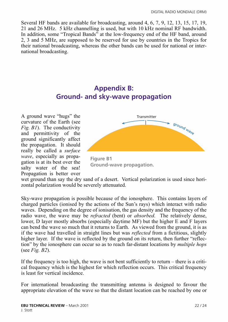
A ground wave “hugs” thecurvature of the Earth (seeFig. B1). The conductivityand permittivity of theground significantly affectthe propagation. It shouldreally be called a surfacewave, especially as propa-gation is at its best over thesalty water of the sea!Propagation is better overwet ground than say the dry sand of a desert. Vertical polarization is used since hori-zontal polarization would be severely attenuated.
Sky-wave propagation is possible because of the ionosphere. This contains layers ofcharged particles (ionised by the actions of the Sun’s rays) which interact with radiowaves. Depending on the degree of ionisation, the gas density and the frequency of theradio wave, the wave may be refracted (bent) or absorbed. The relatively dense,lower, D layer mostly absorbs (especially daytime MF) but the higher E and F layerscan bend the wave so much that it returns to Earth. As viewed from the ground, it is asif the wave had travelled in straight lines but was reflected from a fictitious, slightlyhigher layer. If the wave is reflected by the ground on its return, then further “reflec-tion” by the ionosphere can occur so as to reach far-distant locations by multiple hops(see Fig. B2).
If the frequency is too high, the wave is not bent sufficiently to return – there is a criti-cal frequency which is the highest for which reflection occurs. This critical frequencyis least for vertical incidence.
For international broadcasting the transmitting antenna is designed to favour theappropriate elevation of the wave so that the distant location can be reached by one or
Transmitter
ground wave
Figure B1Ground-wave propagation.
EBU TECHNICAL REVIEW – March 2001 22 / 24J. Stott

DIGITAL RADIO MONDIALE (DRM)
more hops. However, another type of broadcasting deliberately aims the wave upwardso that it is reflected back down to the region surrounding the transmitter (see Fig. B3).This means that it is suitable to provide national coverage, and is useful in conditionswhere ground-wave coverage would be difficult. This Near-vertical incidence sky-wave (NVIS) broadcasting requires the frequency to be below the critical frequency;
The ray is actually refracted , but appears to have been reflected in the ionosphere
Point of apparent reflection
ionosphere
Area served from central upwards-firing transmitter
ionosphere
Figure B2Sky-wave propagation.
Figure B3Near-vertical-incidence sky-wave propagation (the multiple hops after ground reflection are not shown for clarity).
EBU TECHNICAL REVIEW – March 2001 23 / 24J. Stott

DIGITAL RADIO MONDIALE (DRM)
the relatively lower frequency Tropical HF Bands are thus set aside for this purpose. Aparticular feature is that when losses are low enough to support multi-hop propagation,there will be severe multipath, as the first, second, etc. hops can all be received withinthe service area (together with the ground wave if close to the transmitter).
This description of ground- and sky-wave propagation is very much simplified,reflecting the author’s level of understanding of what is a very complicated subject –see the Bibliography for some further reading on this topic.
EBU TECHNICAL REVIEW – March 2001 24 / 24J. Stott


![Draft ETSI EN 303 345 V1.1 · 5 Draft ETSI EN 303 345 V1.1.0 ... "Digital Radio Mondiale (DRM); System Specification". [4] ... frequency-modulated sound broadcasting"](https://img.pdfslide.us/doc/110x75/5aeab0f47f8b9a3b2e8d0c9a/draft-etsi-en-303-345-v11-draft-etsi-en-303-345-v110-digital-radio-mondiale.jpg)