Embed Size (px)
Citation preview
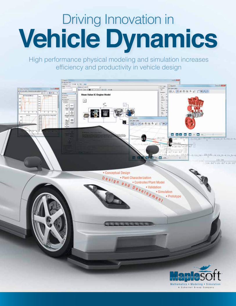
Driving Innovation inVehicle Dynamics
High performance physical modeling and simulation increases efficiency and productivity in vehicle design
A C y b e r n e t G r o u p C o m p a n y
2
Authors
Paul Goossens V.P. of Application Engineering, Maplesoft
Dr. John McPhee Professor, Engineering, University of Waterloo, and NSERC/Toyota/Maple-soft Industrial Research Chair
Dr. Chad Schmitke Director of MapleSim Development, Maplesoft
Dr. Janos Pinter President, PCS Inc.
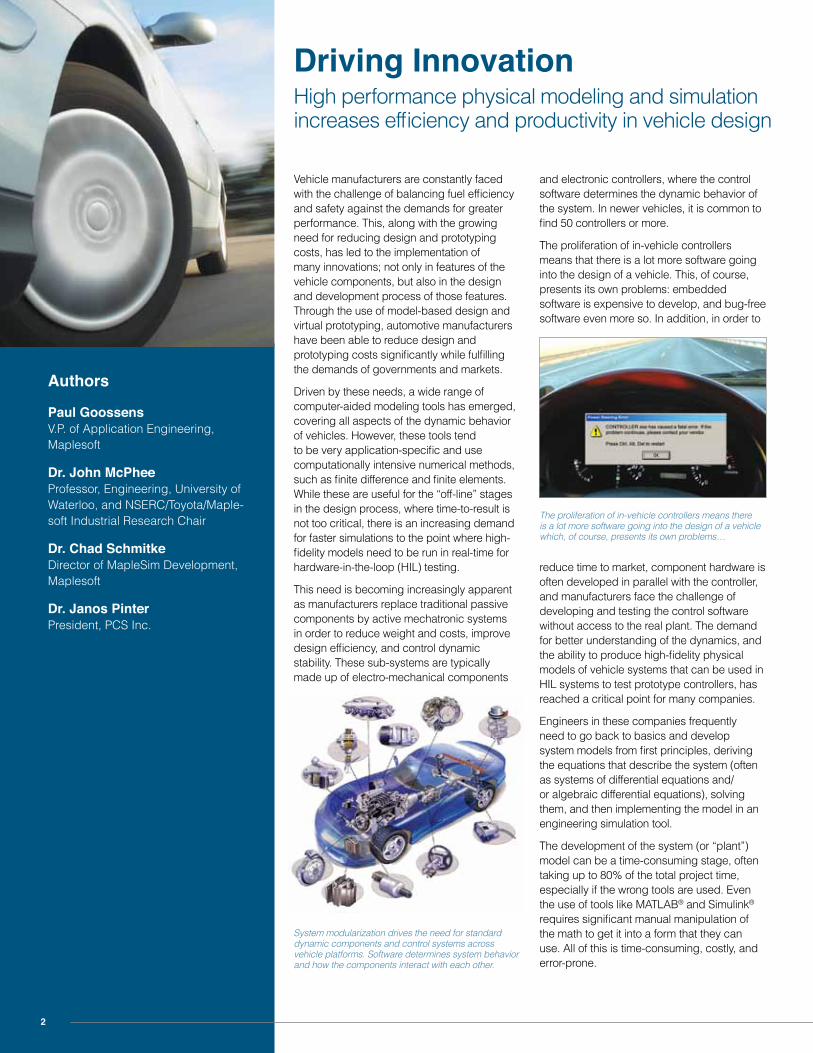
Vehicle manufacturers are constantly faced with the challenge of balancing fuel efficiency and safety against the demands for greater performance. This, along with the growing need for reducing design and prototyping costs, has led to the implementation of many innovations; not only in features of the vehicle components, but also in the design and development process of those features. Through the use of model-based design and virtual prototyping, automotive manufacturers have been able to reduce design and prototyping costs significantly while fulfilling the demands of governments and markets.
Driven by these needs, a wide range of computer-aided modeling tools has emerged, covering all aspects of the dynamic behavior of vehicles. However, these tools tend to be very application-specific and use computationally intensive numerical methods, such as finite difference and finite elements. While these are useful for the “off-line” stages in the design process, where time-to-result is not too critical, there is an increasing demand for faster simulations to the point where high-fidelity models need to be run in real-time for hardware-in-the-loop (HIL) testing.
This need is becoming increasingly apparent as manufacturers replace traditional passive components by active mechatronic systems in order to reduce weight and costs, improve design efficiency, and control dynamic stability. These sub-systems are typically made up of electro-mechanical components
Driving InnovationHigh performance physical modeling and simulation increases efficiency and productivity in vehicle design
and electronic controllers, where the control software determines the dynamic behavior of the system. In newer vehicles, it is common to find 50 controllers or more.
The proliferation of in-vehicle controllers means that there is a lot more software going into the design of a vehicle. This, of course, presents its own problems: embedded software is expensive to develop, and bug-free software even more so. In addition, in order to
reduce time to market, component hardware is often developed in parallel with the controller, and manufacturers face the challenge of developing and testing the control software without access to the real plant. The demand for better understanding of the dynamics, and the ability to produce high-fidelity physical models of vehicle systems that can be used in HIL systems to test prototype controllers, has reached a critical point for many companies.
Engineers in these companies frequently need to go back to basics and develop system models from first principles, deriving the equations that describe the system (often as systems of differential equations and/or algebraic differential equations), solving them, and then implementing the model in an engineering simulation tool.
The development of the system (or “plant”) model can be a time-consuming stage, often taking up to 80% of the total project time, especially if the wrong tools are used. Even the use of tools like MATLAB® and Simulink® requires significant manual manipulation of the math to get it into a form that they can use. All of this is time-consuming, costly, and error-prone.
System modularization drives the need for standard dynamic components and control systems across vehicle platforms. Software determines system behavior and how the components interact with each other.
The proliferation of in-vehicle controllers means there is a lot more software going into the design of a vehicle which, of course, presents its own problems…
3
Vehicle Dynamics Application: Kinematic Modeling, Simulation, and Optimization of a Double-Wishbone Suspension
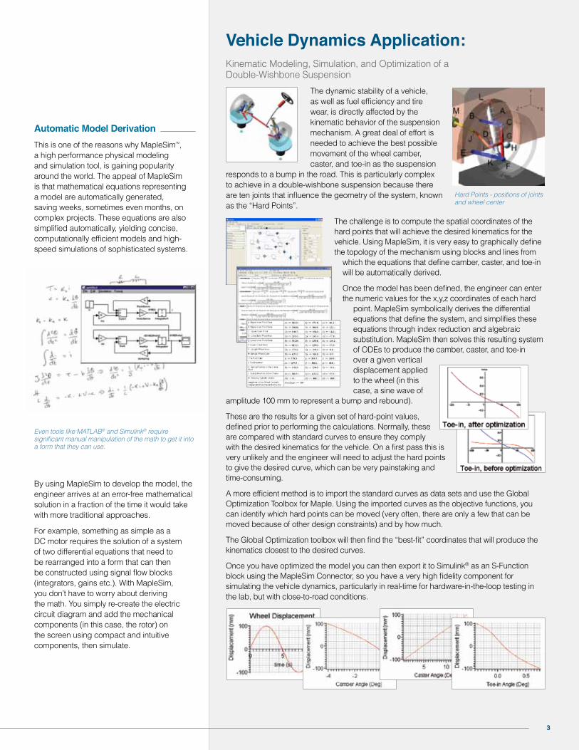
The dynamic stability of a vehicle, as well as fuel efficiency and tire wear, is directly affected by the kinematic behavior of the suspension mechanism. A great deal of effort is needed to achieve the best possible movement of the wheel camber, caster, and toe-in as the suspension
responds to a bump in the road. This is particularly complex to achieve in a double-wishbone suspension because there are ten joints that influence the geometry of the system, known as the “Hard Points”.
The challenge is to compute the spatial coordinates of the hard points that will achieve the desired kinematics for the vehicle. Using MapleSim, it is very easy to graphically define the topology of the mechanism using blocks and lines from
which the equations that define camber, caster, and toe-in will be automatically derived.
Once the model has been defined, the engineer can enter the numeric values for the x,y,z coordinates of each hard
point. MapleSim symbolically derives the differential equations that define the system, and simplifies these equations through index reduction and algebraic substitution. MapleSim then solves this resulting system of ODEs to produce the camber, caster, and toe-in over a given vertical displacement applied to the wheel (in this case, a sine wave of
amplitude 100 mm to represent a bump and rebound).
These are the results for a given set of hard-point values, defined prior to performing the calculations. Normally, these are compared with standard curves to ensure they comply with the desired kinematics for the vehicle. On a first pass this is very unlikely and the engineer will need to adjust the hard points to give the desired curve, which can be very painstaking and time-consuming.
A more efficient method is to import the standard curves as data sets and use the Global Optimization Toolbox for Maple. Using the imported curves as the objective functions, you can identify which hard points can be moved (very often, there are only a few that can be moved because of other design constraints) and by how much.
The Global Optimization toolbox will then find the “best-fit” coordinates that will produce the kinematics closest to the desired curves.
Once you have optimized the model you can then export it to Simulink® as an S-Function block using the MapleSim Connector, so you have a very high fidelity component for simulating the vehicle dynamics, particularly in real-time for hardware-in-the-loop testing in the lab, but with close-to-road conditions.
Hard Points - positions of joints and wheel center
Automatic Model Derivation This is one of the reasons why MapleSimTM, a high performance physical modeling and simulation tool, is gaining popularity around the world. The appeal of MapleSim is that mathematical equations representing a model are automatically generated, saving weeks, sometimes even months, on complex projects. These equations are also simplified automatically, yielding concise, computationally efficient models and high-speed simulations of sophisticated systems.
By using MapleSim to develop the model, the engineer arrives at an error-free mathematical solution in a fraction of the time it would take with more traditional approaches.
For example, something as simple as a DC motor requires the solution of a system of two differential equations that need to be rearranged into a form that can then be constructed using signal flow blocks (integrators, gains etc.). With MapleSim, you don’t have to worry about deriving the math. You simply re-create the electric circuit diagram and add the mechanical components (in this case, the rotor) on the screen using compact and intuitive components, then simulate.
Even tools like MATLAB® and Simulink® require significant manual manipulation of the math to get it into a form that they can use.
4
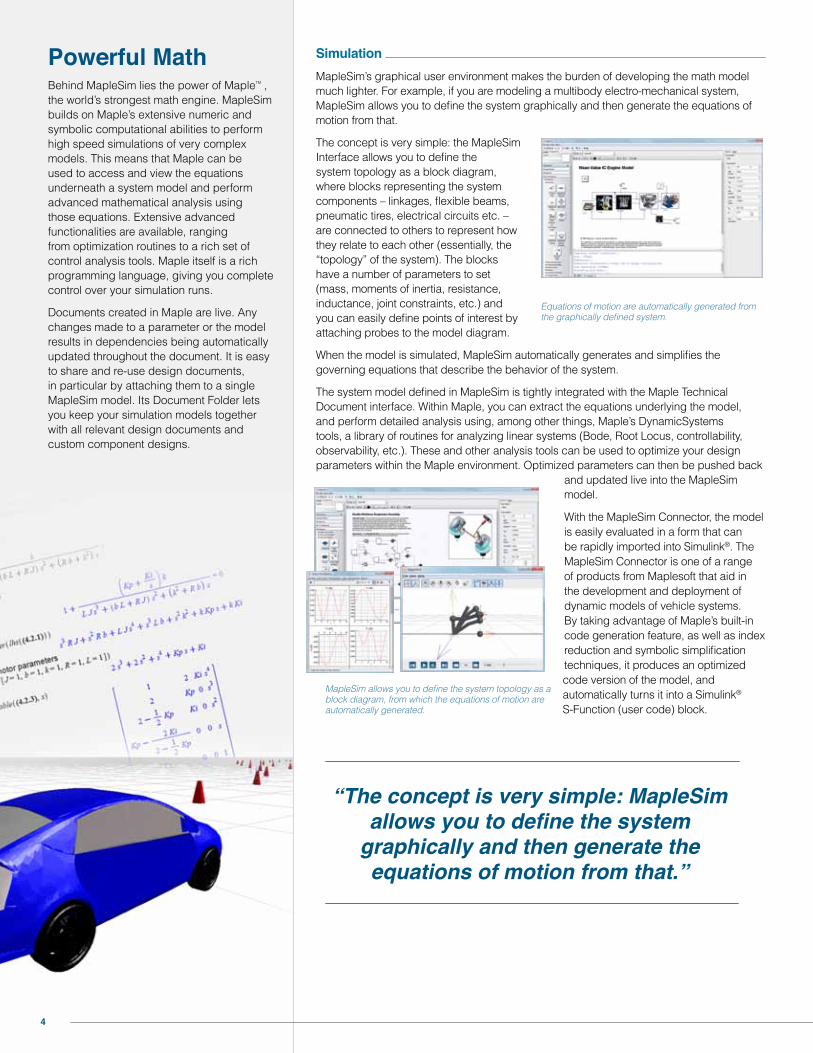
SimulationMapleSim’s graphical user environment makes the burden of developing the math model much lighter. For example, if you are modeling a multibody electro-mechanical system, MapleSim allows you to define the system graphically and then generate the equations of motion from that.
The concept is very simple: the MapleSim Interface allows you to define the system topology as a block diagram, where blocks representing the system components – linkages, flexible beams, pneumatic tires, electrical circuits etc. – are connected to others to represent how they relate to each other (essentially, the “topology” of the system). The blocks have a number of parameters to set (mass, moments of inertia, resistance, inductance, joint constraints, etc.) and you can easily define points of interest by attaching probes to the model diagram.
When the model is simulated, MapleSim automatically generates and simplifies the governing equations that describe the behavior of the system.
The system model defined in MapleSim is tightly integrated with the Maple Technical Document interface. Within Maple, you can extract the equations underlying the model, and perform detailed analysis using, among other things, Maple’s DynamicSystems tools, a library of routines for analyzing linear systems (Bode, Root Locus, controllability, observability, etc.). These and other analysis tools can be used to optimize your design parameters within the Maple environment. Optimized parameters can then be pushed back
and updated live into the MapleSim model.
With the MapleSim Connector, the model is easily evaluated in a form that can be rapidly imported into Simulink®. The MapleSim Connector is one of a range of products from Maplesoft that aid in the development and deployment of dynamic models of vehicle systems. By taking advantage of Maple’s built-in code generation feature, as well as index reduction and symbolic simplification techniques, it produces an optimized code version of the model, and automatically turns it into a Simulink® S-Function (user code) block.
Equations of motion are automatically generated from the graphically defined system.
“The concept is very simple: MapleSim allows you to define the system
graphically and then generate the equations of motion from that.”
MapleSim allows you to define the system topology as a block diagram, from which the equations of motion are automatically generated.
Powerful MathBehind MapleSim lies the power of MapleTM , the world’s strongest math engine. MapleSim builds on Maple’s extensive numeric and symbolic computational abilities to perform high speed simulations of very complex models. This means that Maple can be used to access and view the equations underneath a system model and perform advanced mathematical analysis using those equations. Extensive advanced functionalities are available, ranging from optimization routines to a rich set of control analysis tools. Maple itself is a rich programming language, giving you complete control over your simulation runs.
Documents created in Maple are live. Any changes made to a parameter or the model results in dependencies being automatically updated throughout the document. It is easy to share and re-use design documents, in particular by attaching them to a single MapleSim model. Its Document Folder lets you keep your simulation models together with all relevant design documents and custom component designs.
5
Optimization Toolbox to determine these parameters automatically. This is a relatively simple example to illustrate a point, but the principles can be applied to problems with many variables and constraints.
One of the many areas where the Maple Global Optimization Toolbox is used extensively is in model fitting or calibration. Very often, engineers will have a good theoretical model of a system; however, they do not have the necessary parameter values to make the model behave the same as the real system. In situations like this, you can capture experimental data from the real system to determine the target output of the model and then use optimization techniques to find the necessary parameter values to match that output as closely as possible. Since you are typically dealing with highly non-linear systems, often with dynamic responses, the use of global optimization for this type of application is necessary to obtain the “best fit”. This is a more general, flexible, and more successful model-fitting approach than using traditional statistical regression techniques.
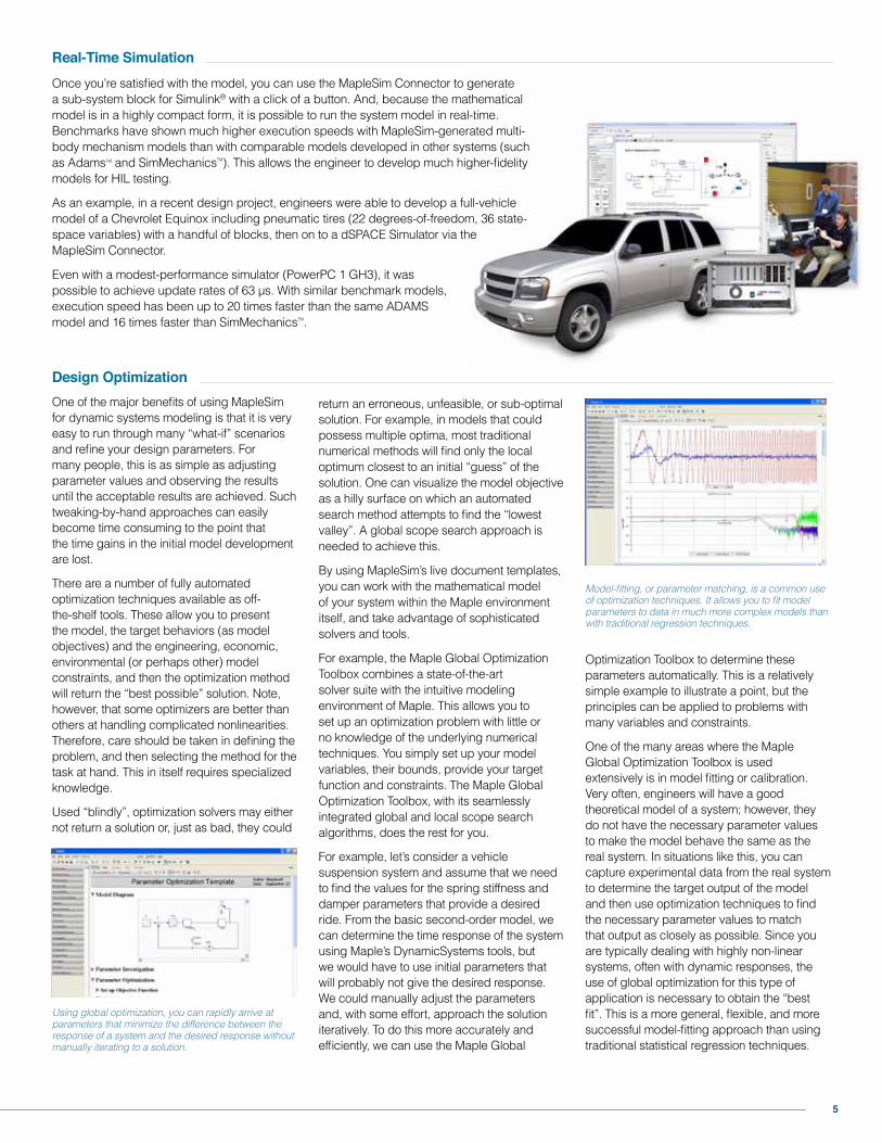
Real-Time SimulationOnce you’re satisfied with the model, you can use the MapleSim Connector to generate a sub-system block for Simulink® with a click of a button. And, because the mathematical model is in a highly compact form, it is possible to run the system model in real-time. Benchmarks have shown much higher execution speeds with MapleSim-generated multi-body mechanism models than with comparable models developed in other systems (such as AdamsTM and SimMechanicsTM). This allows the engineer to develop much higher-fidelity models for HIL testing.
As an example, in a recent design project, engineers were able to develop a full-vehicle model of a Chevrolet Equinox including pneumatic tires (22 degrees-of-freedom, 36 state-space variables) with a handful of blocks, then on to a dSPACE Simulator via the MapleSim Connector.
Even with a modest-performance simulator (PowerPC 1 GH3), it was possible to achieve update rates of 63 μs. With similar benchmark models, execution speed has been up to 20 times faster than the same ADAMS model and 16 times faster than SimMechanicsTM.
Design OptimizationOne of the major benefits of using MapleSim for dynamic systems modeling is that it is very easy to run through many “what-if” scenarios and refine your design parameters. For many people, this is as simple as adjusting parameter values and observing the results until the acceptable results are achieved. Such tweaking-by-hand approaches can easily become time consuming to the point that the time gains in the initial model development are lost.
There are a number of fully automated optimization techniques available as off-the-shelf tools. These allow you to present the model, the target behaviors (as model objectives) and the engineering, economic, environmental (or perhaps other) model constraints, and then the optimization method will return the “best possible” solution. Note, however, that some optimizers are better than others at handling complicated nonlinearities. Therefore, care should be taken in defining the problem, and then selecting the method for the task at hand. This in itself requires specialized knowledge.
Used “blindly”, optimization solvers may either not return a solution or, just as bad, they could
Using global optimization, you can rapidly arrive at parameters that minimize the difference between the response of a system and the desired response without manually iterating to a solution.
return an erroneous, unfeasible, or sub-optimal solution. For example, in models that could possess multiple optima, most traditional numerical methods will find only the local optimum closest to an initial “guess” of the solution. One can visualize the model objective as a hilly surface on which an automated search method attempts to find the “lowest valley”. A global scope search approach is needed to achieve this.
By using MapleSim’s live document templates, you can work with the mathematical model of your system within the Maple environment itself, and take advantage of sophisticated solvers and tools.
For example, the Maple Global Optimization Toolbox combines a state-of-the-art solver suite with the intuitive modeling environment of Maple. This allows you to set up an optimization problem with little or no knowledge of the underlying numerical techniques. You simply set up your model variables, their bounds, provide your target function and constraints. The Maple Global Optimization Toolbox, with its seamlessly integrated global and local scope search algorithms, does the rest for you.
For example, let’s consider a vehicle suspension system and assume that we need to find the values for the spring stiffness and damper parameters that provide a desired ride. From the basic second-order model, we can determine the time response of the system using Maple’s DynamicSystems tools, but we would have to use initial parameters that will probably not give the desired response. We could manually adjust the parameters and, with some effort, approach the solution iteratively. To do this more accurately and efficiently, we can use the Maple Global
Model-fitting, or parameter matching, is a common use of optimization techniques. It allows you to fit model parameters to data in much more complex models than with traditional regression techniques.
6
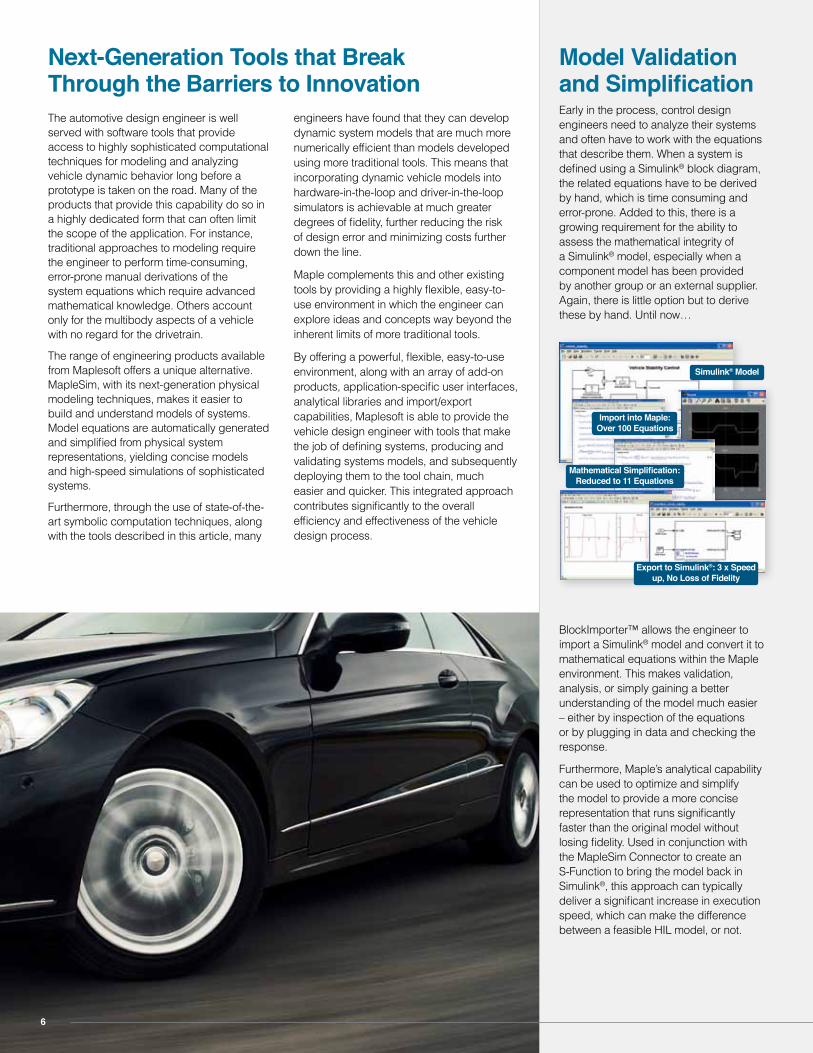
Model Validation and SimplificationEarly in the process, control design engineers need to analyze their systems and often have to work with the equations that describe them. When a system is defined using a Simulink® block diagram, the related equations have to be derived by hand, which is time consuming and error-prone. Added to this, there is a growing requirement for the ability to assess the mathematical integrity of a Simulink® model, especially when a component model has been provided by another group or an external supplier. Again, there is little option but to derive these by hand. Until now…
BlockImporter™ allows the engineer to import a Simulink® model and convert it to mathematical equations within the Maple environment. This makes validation, analysis, or simply gaining a better understanding of the model much easier – either by inspection of the equations or by plugging in data and checking the response.
Furthermore, Maple’s analytical capability can be used to optimize and simplify the model to provide a more concise representation that runs significantly faster than the original model without losing fidelity. Used in conjunction with the MapleSim Connector to create an S-Function to bring the model back in Simulink®, this approach can typically deliver a significant increase in execution speed, which can make the difference between a feasible HIL model, or not.
The automotive design engineer is well served with software tools that provide access to highly sophisticated computational techniques for modeling and analyzing vehicle dynamic behavior long before a prototype is taken on the road. Many of the products that provide this capability do so in a highly dedicated form that can often limit the scope of the application. For instance, traditional approaches to modeling require the engineer to perform time-consuming, error-prone manual derivations of the system equations which require advanced mathematical knowledge. Others account only for the multibody aspects of a vehicle with no regard for the drivetrain.
The range of engineering products available from Maplesoft offers a unique alternative. MapleSim, with its next-generation physical modeling techniques, makes it easier to build and understand models of systems. Model equations are automatically generated and simplified from physical system representations, yielding concise models and high-speed simulations of sophisticated systems.
Furthermore, through the use of state-of-the-art symbolic computation techniques, along with the tools described in this article, many
engineers have found that they can develop dynamic system models that are much more numerically efficient than models developed using more traditional tools. This means that incorporating dynamic vehicle models into hardware-in-the-loop and driver-in-the-loop simulators is achievable at much greater degrees of fidelity, further reducing the risk of design error and minimizing costs further down the line.
Maple complements this and other existing tools by providing a highly flexible, easy-to-use environment in which the engineer can explore ideas and concepts way beyond the inherent limits of more traditional tools.
By offering a powerful, flexible, easy-to-use environment, along with an array of add-on products, application-specific user interfaces, analytical libraries and import/export capabilities, Maplesoft is able to provide the vehicle design engineer with tools that make the job of defining systems, producing and validating systems models, and subsequently deploying them to the tool chain, much easier and quicker. This integrated approach contributes significantly to the overall efficiency and effectiveness of the vehicle design process.
Next-Generation Tools that Break Through the Barriers to Innovation
Mathematical Simplification: Reduced to 11 Equations
Export to Simulink®: 3 x Speed up, No Loss of Fidelity
Import into Maple: Over 100 Equations
Simulink® Model
7
Author’s Biographies Illustrative References
Pintér, J.D. (1996) Global Optimization in Action. (Continuous and Lipschitz Optimization: Algorithms, Implementations and Applications.) Kluwer Academic Publishers, Dordrecht. Now distributed by Springer Science and Business Media, New York.
Pintér, J.D. (2006) Global Optimization with Maple: An Introduction with Illustrative Examples. An electronic book published by Pintér Consulting Services, Halifax, NS and Maplesoft, Waterloo, ON.
Pintér, J. D. (Ed.) (2006) Global Optimization: Scientific and Engineering Case Studies. Springer Science and Business Media, New York.
Autobeat Daily: Improving the Reliability of Networked Electronics, An interview with Kevin Kott, President dSPACE North America. http://www.dspaceinc.com/shared/data/pdf/press/autobeat_viewpoint_dspace_060426.pdf
Blundell, M. and Harty, D.: The Multibody Systems Approach to Vehicle Dynamics. Elsevier Butterworth-Heinemann, 2004
He, Y. and McPhee, J.: A Review of Automated Design Synthesis Approaches for Virtual Development of Ground Vehicle Suspensions, SAE Congress 2007
K. Morency, J. McPhee, and C. Schmitke, Using Graph Theory and Symbolic Computing to Generate Efficient Models for Vehicle Dynamics, Proc. CSME Forum, Alberta, 19 pages, 2006.
Reimpell, J., Stoll, H. and Betzler, J: The Automotive Chassis, Engineering Principles, Second Edition, SAE International
Bhatt, R.M. and Krovi V.N.: Product Review: DynaFlexPro for Maple, IEEE Control Systems Magazine, Volume 26 Issue 6, December 2006.
Paul Goossens, V.P. of Application Engineering, Maplesoft
Paul directs the Applications Engineering Group that supports Maplesoft’s new line of engineering modeling products. A mechanical engineer by background, Paul has over 20 years of experience in both engineering and software business management. Past positions included senior management positions for companies in engineering modeling solutions and high-performance real-time simulations.
Dr. John McPhee, Professor, Engineering, University of Waterloo, and NSERC/Toyota/Maplesoft Industrial Research Chair
Dr. John McPhee is a Professor in Systems Design Engineering, and the NSERC/Toyota/Maplesoft Industrial Research Chair in Mathematics-based Modeling and Design. Dr. McPhee’s main area of research is multibody system dynamics, with principal application to the analysis and design of vehicles, mechatronic devices, and biomechanical systems. He has won many awards, including a Premier’s Research Excellence Award and the I.W. Smith Award from the Canadian Society of Mechanical Engineers. Dr. McPhee completed his term in 2009 as the Executive Director of the Waterloo Centre for Automotive Research, spending a sabbatical year at the Toyota Technical Center in Ann Arbor, Michigan. He holds a PhD in Mechanical Engineering from the University of Waterloo, Canada.
Dr. Chad Schmitke, Director, MapleSim Development, Maplesoft
Dr. Schmitke holds a Ph.D. in Systems Design Engineering from the University of Waterloo, where he serves as an adjunct professor. His research focuses on the symbolic modeling of multibody mechatronic systems. Before joining Maplesoft, Chad worked as Chief Developer at MotionPro, and at the Canadian Space Agency as a post-doctoral fellow, developing tools for modeling robotic manipulators.
Dr. János D. Pintér, President, PCS Inc.
János Pintér, Ph.D., D.Sc. has authored and edited several books and published more than 180 other peer-reviewed papers and other technical documents. He has run PCS Inc. since 1994, and he is also an adjunct professor at Dalhousie University, in Halifax, Nova Scotia, Canada. Dr. Pintér’s R&D, consulting, and teaching activities are related to the application of advanced optimization technology across a range of business, engineering, and scientific decision problems.
A C y b e r n e t G r o u p C o m p a n y
© Maplesoft, a division of Waterloo Maple Inc., 2014. Maplesoft, Maple, and MapleSim are trademarks of Waterloo Maple Inc. MATLAB, Simulink, and SimMechanics are trademarks or registered trademarks of The Mathworks, Inc. Adams is a trademark of the MSC Software Corporation in the United States and/or other countries.
All other trademarks are the property of their respective owners.
www.maplesoft.com | [email protected] Toll-free: (US & Canada) 1-800-267-6583 | Direct:1-519-747-2373
Maplesoft
Reduce Development Risk. Create Better Products. Get to Market Faster.
Maplesoft Engineering Solutions provide you with the expertise and tools you need to meet your project requirements quickly and effectively. Offering experts in a variety of engineering fields, extensive experience in model-based design, and the superior system-level modeling and analysis tools MapleSim and Maple, Maplesoft can help you reduce development risk and bring high-quality products to market faster.
Talk to a Maplesoft Engineering Solutions expert to learn how we can help you with your design projects.
www.maplesoft.com
The Essential Tool for Mathematics and Modeling
SERVICESMAPLESOFT
Products
Develop system-level models with MapleSim and Maple, and dramatically reduce model development time, gain greater insight into system behavior, and produce fast, high-fidelity simulations.
Services
With expertise in a variety of engineering fields and extensive experience in model-based design, Maplesoft experts are available to help you solve your engineering design problems.


![Lecce, ItalyIEEE Control Systems Magazine 26 (2006), 34 61. [4] M. Mitschke. Driver-vehicle-lateraldynamics under regular driving conditions. Vehicle System Dynamics 22 (1993), 483](https://img.pdfslide.us/doc/110x75/5f01b66e7e708231d400ade5/lecce-italy-ieee-control-systems-magazine-26-2006-34-61-4-m-mitschke-driver-vehicle-lateraldynamics.jpg)