Embed Size (px)
Citation preview

Gaylord Industries
10900 SW Avery St.
Tualatin, OR 97067
Office: 503.691.2010
Toll Free: 800.547.9696
Website: www.gaylordusa.com
“Drives not provided by Gaylord Industries”
DCV(R or F) – Series Demand Control Ventilation
Variable Frequency Drive (VFD) Programming Specification
(Single Exhaust Blower with Independently controlled MUA System)
Revised December 5, 2013
Hardware: (Minimum VFD Requirements)
1. Works with a 4-20 mA analog input.
2. Produces a 24 VDC or equivalent common to be used for remote dry contact switching of the VFD(s). Independent power supply also accepted.
3. Drive to motor distance is less than the maximum specified by the drive manufacturer.
4. Drive is to be sized appropriately for motor rated FLA, and voltage inputs.
5. Makeup Air VFD to be modulated based on complementary input from Exhaust VFD, or controlled indirectly by BMS or pressure transducer.
Drive Inputs from Gaylord DCV Command Center:
1. Terminals +24 & ES will provide contact closure to start the variable frequency drive(s).
2. A single 4-20 mA Analog Signal will be used to modulate the exhaust fan.
Program Specification:
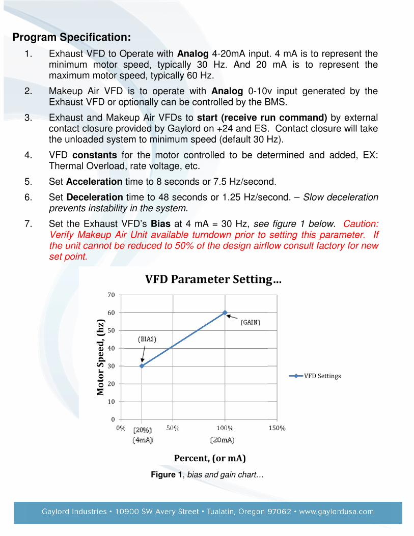
1. Exhaust VFD to Operate with Analog 4-20mA input. 4 mA is to represent the minimum motor speed, typically 30 Hz. And 20 mA is to represent the maximum motor speed, typically 60 Hz.
2. Makeup Air VFD is to operate with Analog 0-10v input generated by the Exhaust VFD or optionally can be controlled by the BMS.
3. Exhaust and Makeup Air VFDs to start (receive run command) by external contact closure provided by Gaylord on +24 and ES. Contact closure will take the unloaded system to minimum speed (default 30 Hz).
4. VFD constants for the motor controlled to be determined and added, EX: Thermal Overload, rate voltage, etc.
5. Set Acceleration time to 8 seconds or 7.5 Hz/second.
6. Set Deceleration time to 48 seconds or 1.25 Hz/second. – Slow deceleration prevents instability in the system.
7. Set the Exhaust VFD’s Bias at 4 mA = 30 Hz, see figure 1 below. Caution: Verify Makeup Air Unit available turndown prior to setting this parameter. If the unit cannot be reduced to 50% of the design airflow consult factory for new set point.
Figure 1, bias and gain chart…
0
10
20
30
40
50
60
70
0% 50% 100% 150%
Mo
tor
Sp
ee
d, (
hz
)
Percent, (or mA)
VFD Parameter Setting…
VFD Settings
8. Set the Exhaust VFD’s Gain 20 mA = 60 Hz. See figure 1 for more details.
9. Makeup Air: Set Exhaust VFD to output a proportional signal to be used to set the speed for the makeup air system. See Gaylord DCV Series Technical Manual for setting the minimum makeup air drive speeds. Caution: confirm the minimum air volumes do not exceed the makeup air unit’s available turndown. Consult the Makeup air unit’s installation manual.
10. Set the Makeup Air VFD Bias such that the minimum speed signal from the Exhaust VFD corresponds to the minimum speed frequency of the Makeup Air VFD.
11. Set the Makeup Air VFD’s Gain such that the maximum speed signal from the Exhaust VFD corresponds to the maximum speed frequency of the Makeup Air VFD.
12. Fire Protection (By others): If VFDs are provided by others the FP interface will be missing. It is recommended that systems in fire mode will override the demand control ventilation and take the exhaust fans to 100% while shutting down the supply fans, (NO Fire Damper systems ONLY). Systems with fire dampers will need to consult the hood manufacturer listing for details on how the system is to be run in the event of a fire conditions. When the Gaylord Industries DCV system is provided without the drives, fire protection interfaces and programming will be provided by others.