Embed Size (px)
Citation preview

Driver Sleep Detection and Alarming System
Final Report
ECE445: Senior Design Project
Team No.15
Team member: Chenyang Xu, Xiangyu Chen, Yixiao Nie
TA: Mustafa Mukadam
Date: December 11th, 2013
University of Illinois at Urbana-Champaign
1
Abstract
Feeling sleepy while driving could cause hazardous traffic accident. However,
when driving alone on highway or driving over a long period of time, drivers are
inclined to feel bored and sleepy, or even fall asleep. Nowadays most of the products
of driver anti-sleep detection sold in the market are simply earphone making
intermittent noises, which is quite annoying and inefficient. As such, there is a high
demand for cheap and efficient driver sleep detection. Therefore, we came up with an
idea and successfully developed a sleepy detection and alarming system, which could
effectively meet this demand.

2
Table of Contents
1. Introduction
1.1 Project motivation and purpose
1.2 Project functions
1.3 Hardware system overview/ block diagram
2. Design of Project
2.1. General design alternatives
2.2. Simulation Circuits Schematic and Calculation
2.2.1 Cadence simulation of switching regular
2.2.2 Circuit parameters calculation
2.3. Block description
2.3.1 Software flow chart and algorithm description
2.3.2 Hardware components
2.4. Schematics with components
3. Verifications
3.1. Testing Procedure
3.2. Quantitative results and Measurements
3.3. Discussion of results and performance
4. Cost
4.1. Labor cost
4.2. Components and device cost

3
4.3. Grand Total
5. Conclusion
5.1. Accomplishments
5.2. Ethnics
5.3. Future work
5.4. Uncertainty
6. References
7. Appendix
4
1. Introduction
1.1. Project motivation and purpose
The goal of this project is to develop a system that can accurately detect sleepy
driving and make alarms accordingly, which aims to prevent the drivers from drowsy
driving and create a safer driving environment. The project was accomplished by a
Webcam that constantly takes image of driver, a beagle board that implement image
processing algorithm of sleepy detection, and a feedback circuit that could generate
alarm and a power supply system.
1.2.Functions and Features
This system has many features that make it unique and functional. These features
include:
1. Eye extraction, use open and close to determine sleepiness
2. Daytime and night detection
3. Real time image processing and detection
4. Sound and flashing LED warning system to redraw driver’s attention
5. Little inference and potential hazard to driver’s normal driving
6. Portable size with car cigarette charger socket power supply
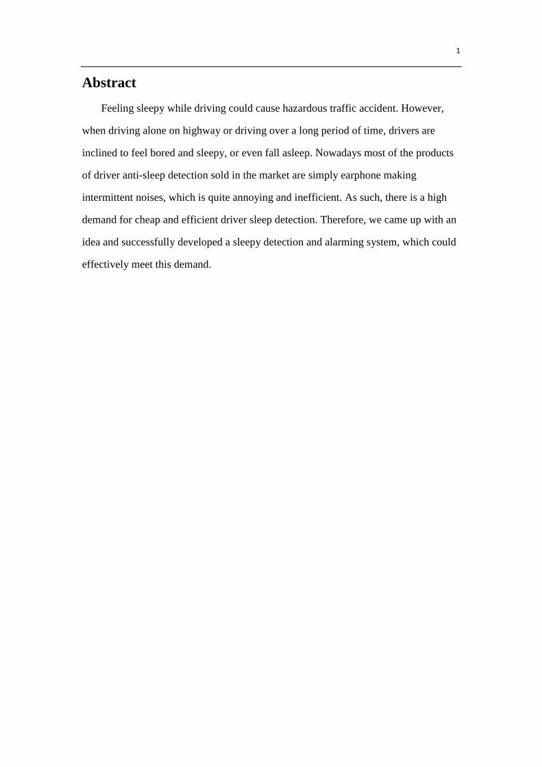
1.3 Hardware system overview/ block diagram
Figure 1. The systematic level block diagram
5
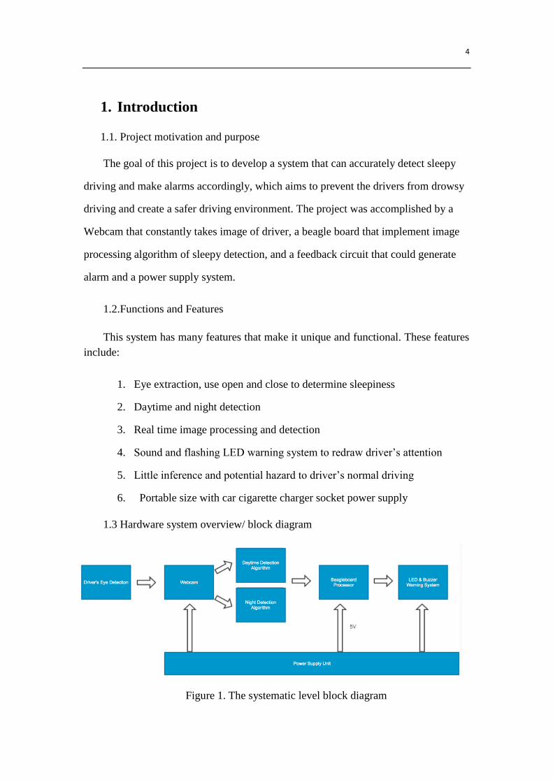
Figure 2. Hardware system connection
2. Design of Project
2.1. General design alternatives
The first alternative design between the final implementation and the initial plan,
for the software part, is the choice of the camera. We desired to use kinect for
capturing the input images at first. However, in pragmatic application, we found out
in order to connect the Kinect, three drivers need to be installed, which are OpenNI,
NITE and Sensor Kinect. Though these three can be successfully installed on the
computer and run the Kinect, the exactly same files could not be installed on the
Beagleboard. We found out that was because the Beagleboard could not understand
the binary file format. However, despite of this change in our plan, we still
successfully implemented both the daytime detection and night detection, based on
the advancement of algorithm. The accuracy is pretty high, which reaches 93% at
daytime and 82% at night. Another advantage of changing the camera is the
significant cost reduction. The new webcam is only 6 dollars while the Kinect is more
than 99 dollars. The anther alternative is the adding of the battery. In order to meet the
rigorous requirement of power supply of Beagle board, a USB battery module is used
intermediately. This alternative solution makes the product more portable and

6
sustainable since the Battery can be easily and constantly charged by the dc-dc power
converter. Meanwhile, the dc power converter can be supplied by cigarette power jack
installed on the car, which turns this alternative into an advantage.
2.2. Simulation Circuits Schematic and Calculation
2.2.1 Cadence simulation of switching regular
The first stage simulation was done in Spice for the TI 61030 dc-dc regulator. The
recommended inductor and capacitor value is calculated. Afterwards, due to the real
application requirements, the design used both TI 61030 boost dc-dc converter and TI
2679 buck dc-dc switching regulator in later phase. The figure shows the prime
simulation for TI 610303 boost converter. There are tally 5 simulation finished and
three of five are shown from figure 3 to figure 5. The input power supply is changed
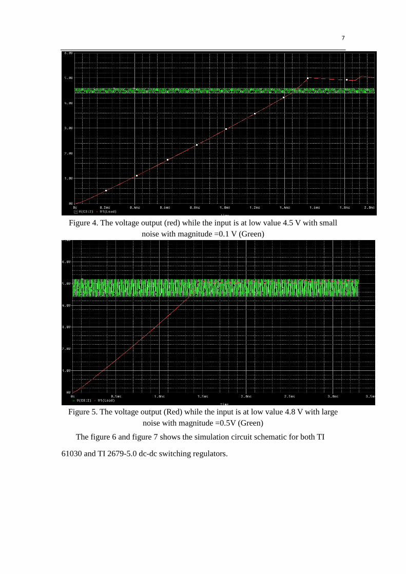
from 1.8V to 5V to simulate the extreme conditions. A sinusoidal function generator
is used to emulate the high frequency noise possible delivered from car charger
inverter. As the graphs show, the output from the chip can be stabled at 5V regardless
of the noise and the input voltage value. Moreover, the noise of the signal is filtered
apparently in the output. The simulation is conducted with a load approximated 10 W.
Figure 3. The voltage output (Red) while the input is at low value 3.3 V with small
noise with magnitude 0.1 V (Green)
7
Figure 4. The voltage output (red) while the input is at low value 4.5 V with small
noise with magnitude =0.1 V (Green)
Figure 5. The voltage output (Red) while the input is at low value 4.8 V with large
noise with magnitude =0.5V (Green)
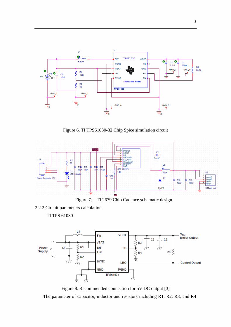
The figure 6 and figure 7 shows the simulation circuit schematic for both TI
61030 and TI 2679-5.0 dc-dc switching regulators.
8
Figure 6. TI TPS61030-32 Chip Spice simulation circuit
Figure 7. TI 2679 Chip Cadence schematic design
2.2.2 Circuit parameters calculation
TI TPS 61030
Figure 8. Recommended connection for 5V DC output [3]
The parameter of capacitor, inductor and resistors including R1, R2, R3, and R4

9
are calculated. The C1 C2 C3 are selected based on the recommendation values
provided from the datasheet. It denotes C2 is 2.2uF, C3 is 220uf and C1 is 10uf to
achieve the best filter and energy conversion result under 5V output condition.
Resistor selection
The DC_DC regulator requires the voltage on FB and LBI no large than 500 mV.
Moreover, the current through the resistive divider is required to be about 100 times
greater than the current into the FB pin. The typical current into FB is 0.01 uA
according to datasheet. To fulfill all these requirements and keep the divider current
more than 1 uA, the R4 is chosen to be 180 kΩ. To achieve 5V output, according to
the equation below, it requires the R3 to be 1620K Ω. Thus, the total resistance on
output current divider is 1800 K Ω. The current flow through the branch is 2.5 uA
which is greater than 100 times of 1uA. The voltage on FB pin is 500 mV as required.
The output is programed to be 5V.
The LBI pin is reference voltage threshold generated on-chip. The lowest
possible voltage supply, that is, Vbat in the equation below is 3 V as the lowest input
voltage. In order to fulfill the current requirement, the R2 is recommended to be 390K
Ω.
Therefore, the R1 is calculated to be 1950 K Ω.The current flow through is
2.13uA. The exact value selection of the R1 R2 R3 R4 is not rigid. Only the ratio,
current limit and voltage limit should be considered to implement the desired output.
Inductor selection
Using same calculations shown below, inductor value can be chosen. The Vbat is
using 3V and the frequency of the chip is 600KHZ. The delta IL is maximum the
current ripple, which is 10% of 3A according to our design. The output voltage is 5V.

10
The calculation result of the current through inductor is 6A and the required
inductor is 6.7 uH. In the simulation, the value of inductor is set to be 6.8uH due to
the availability of the inductor. This effectiveness of this value is validated by the
simulation result.
TI 2679-5.0
Figure 9. Recommended connection for 5V DC output [4]
The boost capacitor, soft start capacitor, inductor values are selected according to
recommendations provided by [4]. The input, output capacitor and current adjust
resistor values are adjusted by the testing of PCB performance.
Table 1. Components selection for TI 2670-5.0
CIN COut CBoost Inductor (L) Radj Css
90uF 300uF 0.01uF 22uH 5.3 K 1nF
2.3. Block description
11
2.3.1 Software flow chart and algorithm description
The algorithm aims to accurately detect the sleepiness of the driver by open eye
and close eye recognition. The sleepy detection algorithm is built on C++ and
OpenCV library. The test was first implemented and tested on the computer, then on
the Beagleboard. The algorithm includes two parts: daytime detection and night
detection. First and Foremost, based on the average intensity of pixels, the algorithm
classifies the environment as daytime or night. For daytime, the image quality is good
enough, therefore no image enhancement is required; for night, because the poor
contrast of the images, histogram equalization, a method to expand the color range of
the image from 0 to 255, is implemented. In this case, we need a light the slightly
illuminate the driver.
In the next step, as soon as the driver has entered the car, two base images are
recorded automatically – open eye as well as close eye. These two images are used as
the base for further determination of whether the drivers’ eye is open or close.
Afterwards, the driver could start driving. The detection algorithm is in real time
and the eye portion is extracted by using the iterative Haar Classifier. After the current
eye portion is extracted, we use template matching function built in OpenCV to
determine if the eye is open or close. If the eye has been closed for more than two
seconds, sleepiness is detected and the program will send a signal to Beagleboard.
The detailed flow chart of the algorithm is shown below.
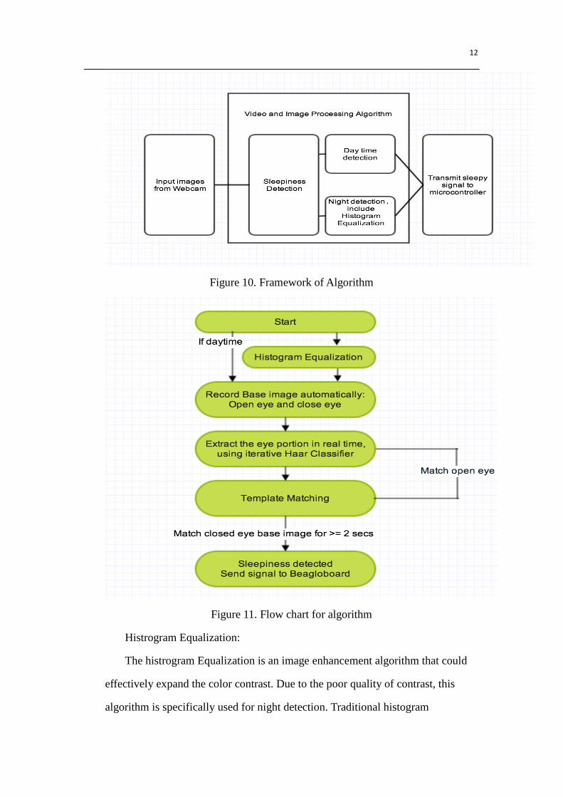
12
Figure 10. Framework of Algorithm
Figure 11. Flow chart for algorithm
Histrogram Equalization:
The histrogram Equalization is an image enhancement algorithm that could
effectively expand the color contrast. Due to the poor quality of contrast, this
algorithm is specifically used for night detection. Traditional histogram
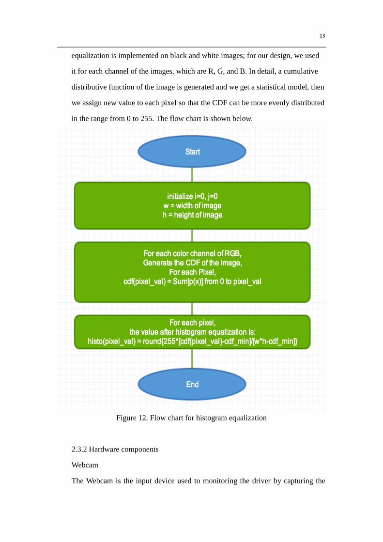
13
equalization is implemented on black and white images; for our design, we used
it for each channel of the images, which are R, G, and B. In detail, a cumulative
distributive function of the image is generated and we get a statistical model, then
we assign new value to each pixel so that the CDF can be more evenly distributed
in the range from 0 to 255. The flow chart is shown below.
Figure 12. Flow chart for histogram equalization
2.3.2 Hardware components
Webcam
The Webcam is the input device used to monitoring the driver by capturing the

14
face images. The images are then sent to the Beagle board for processing. The camera
will be placed in front of the driver.
BeagleBoard
The Beagle Board would operate as the controller for all other components. First,
it will send and collect information from the webcam. Then it would perform
algorithms to determine the status of the driver to see whether his/her eyes are closed
or not. Last it will send out 1.8V control signals to LED array and buzzer to control
them. In order to collect information, analyze data, and send out feedback, we need to
install Linux and openCV on the board and build corresponding drivers for other
components. Even though power to BeagleBoard can be supplied via the USB OTG
connector, the USB Host ports cannot supply power to our webcam. Therefore we
used the DC power jack to supply power for BeagleBoard, using a Generic USB to
5.5 mm/2.1 mm 5 Volt DC Barrel Jack Power Cable that connected with the
DXPOWER USB battery.
Our BeagleBoard will power and communicate with webcam using one of the
four USB Host ports. We’ll install Ubuntu on the board and use openCV library to
support our algorithms. Most or the program is in C++ and compiled by g++, with a
few bash commands to interact with the GPIO pins.
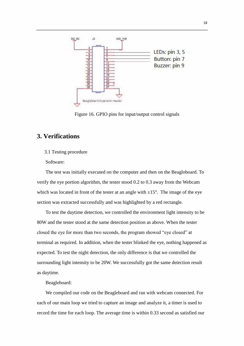
As for the input from buttons and output to alarming systems, we plan to use
GPIO pins on the Beagleboard. Currently, we are using pin3(GPIO_139) and
5(GPIO_138), on the Expansion Header to control the LEDs, pin9(GPIO_136) for
buzzer, and pin 7(GPIO_17) for the button. When the button is pressed, our system
would continue running our program and record images of open and closed eyes.
After the initialization is done, the board will run our algorithm to detect the driver’s
eyes, and notify the user by LED and buzzer when a dangerous signal appears.
Power Supply/Control Unit
For the final design, in order to make the overall system portable, the power
source is provided by the car cigarette power outlet, which typically has 12V DC

15
supply. Occasionally it also provides 24 V DC. The power supply unit can tolerate 8V
to 24 V inputs and provide a filtered steady 5 V output to supply the USB battery
which is used to power up the Beagle board and the camera. Also, it is used to power
up the Buzzer and to illuminate the LED array by connecting appropriate resistors.
One or Two USB receptor ports will be used to retrieve power and one USB outlet
will connected to Beagle board. This module also provides one control signals to
beagle board managed by the pushbutton. The pushbutton will control the beagle
board and camera to take users’ initial reference photos when it is pressed. The
estimated working power consumption for the beagle board and camera is estimated
to be 12 W, which is 2.4 A maximum current with output voltage of 5V. Additionally,
a slide switch is installed in order to disable the alarming system when it is not
needed.
Alarming system
Buzzer
The buzzer is chosen to work under 4V to 7V DC with 2.4 KHz alarming sound.
It will directly connect to the power bus but not DC-DC converter output since it has
a relatively large tolerance of functional voltage. Also, it can mitigate the load of the
regulator.
Four through hole LED lights
There will be four LED on the PCB board in total. These LED are used for
alarming purpose. There are three red LEDs put in series. In color selection is based
on the minimum inference of driver by warm color light. The typical working voltage
of these LEDs is 2.1 V. The power supply of LED will from the power bus connected
from USB input. In order to limit the voltage, a series resistor is used to prevent LED
from damage of over voltage. In order to achieve the adjustable frequency of the LED
flashing, each LED is controlled by a NMOS switch, which is described as below.
NMOS switch
The control signal of the Gate for NMOS directly comes from Beagle board. The
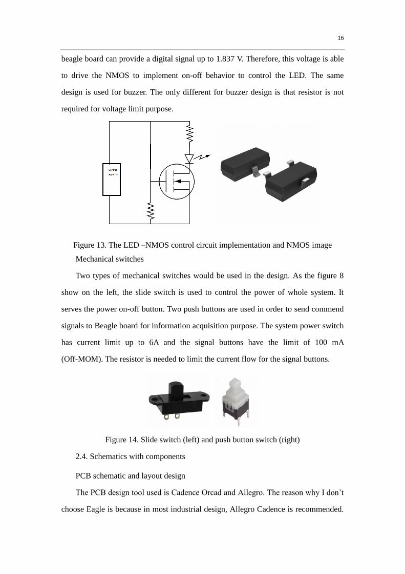
16
beagle board can provide a digital signal up to 1.837 V. Therefore, this voltage is able
to drive the NMOS to implement on-off behavior to control the LED. The same
design is used for buzzer. The only different for buzzer design is that resistor is not
required for voltage limit purpose.
Figure 13. The LED –NMOS control circuit implementation and NMOS image
Mechanical switches
Two types of mechanical switches would be used in the design. As the figure 8
show on the left, the slide switch is used to control the power of whole system. It
serves the power on-off button. Two push buttons are used in order to send commend
signals to Beagle board for information acquisition purpose. The system power switch
has current limit up to 6A and the signal buttons have the limit of 100 mA
(Off-MOM). The resistor is needed to limit the current flow for the signal buttons.
Figure 14. Slide switch (left) and push button switch (right)
2.4. Schematics with components
PCB schematic and layout design
The PCB design tool used is Cadence Orcad and Allegro. The reason why I don’t
choose Eagle is because in most industrial design, Allegro Cadence is recommended.
17
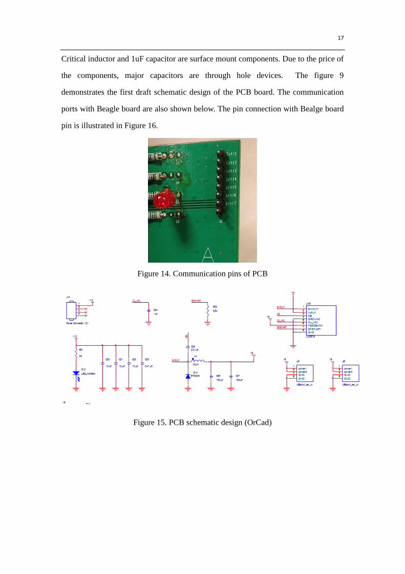
Critical inductor and 1uF capacitor are surface mount components. Due to the price of
the components, major capacitors are through hole devices. The figure 9
demonstrates the first draft schematic design of the PCB board. The communication
ports with Beagle board are also shown below. The pin connection with Bealge board
pin is illustrated in Figure 16.
Figure 14. Communication pins of PCB
Figure 15. PCB schematic design (OrCad)
18
Figure 16. GPIO pins for input/output control signals
3. Verifications
3.1 Testing procedure
Software:
The test was initially executed on the computer and then on the Beagloboard. To
verify the eye portion algorithm, the tester stood 0.2 to 0.3 away from the Webcam
which was located in front of the tester at an angle with ±15°. The image of the eye
section was extracted successfully and was highlighted by a red rectangle.
To test the daytime detection, we controlled the environment light intensity to be
80W and the tester stood at the same detection position as above. When the tester
closed the eye for more than two seconds, the program showed “eye closed” at
terminal as required. In addition, when the tester blinked the eye, nothing happened as
expected. To test the night detection, the only difference is that we controlled the
surrounding light intensity to be 20W. We successfully got the same detection result
as daytime.
Beagleboard:
We compiled our code on the Beagleboard and ran with webcam connected. For
each of our main loop we tried to capture an image and analyze it, a timer is used to
record the time for each loop. The average time is within 0.33 second as satisfied our
19
requirement. For the GPIO pin output, we were able to send out a control signal
varying from 1.788V to 1.835V which satisfied our requirement(1.8V±5%). These
control signals were able to drive LEDs and buzzer successfully. For the GPIO pin
output, we fed a control signal of 0V to the pin and our program is able to identify
that the pin is set to low, which meets our requirement.
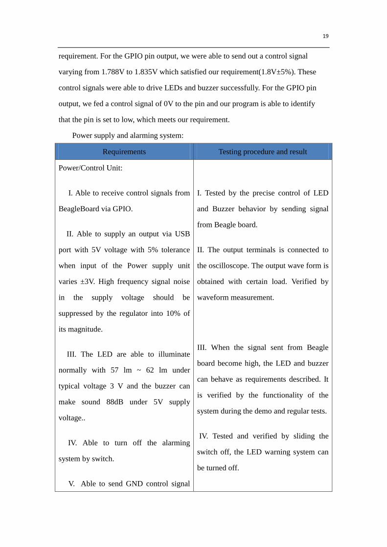
Power supply and alarming system:
Requirements Testing procedure and result
Power/Control Unit:
I. Able to receive control signals from
BeagleBoard via GPIO.
II. Able to supply an output via USB
port with 5V voltage with 5% tolerance
when input of the Power supply unit
varies ±3V. High frequency signal noise
in the supply voltage should be
suppressed by the regulator into 10% of
its magnitude.
III. The LED are able to illuminate
normally with 57 lm ~ 62 lm under
typical voltage 3 V and the buzzer can
make sound 88dB under 5V supply
voltage..
IV. Able to turn off the alarming
system by switch.
V. Able to send GND control signal
I. Tested by the precise control of LED
and Buzzer behavior by sending signal
from Beagle board.
II. The output terminals is connected to
the oscilloscope. The output wave form is
obtained with certain load. Verified by
waveform measurement.
III. When the signal sent from Beagle
board become high, the LED and buzzer
can behave as requirements described. It
is verified by the functionality of the
system during the demo and regular tests.
IV. Tested and verified by sliding the
switch off, the LED warning system can
be turned off.
20
to Beagle board in order to take initial
pictures for driver for reference.
V. Tested and verified by pressing the
button to see the response from Beagle
board. The beagle board successfully
receives the GND signal.
Alarming devices
I. LEDs are able to flash at same
frequency in different sequences. The
frequencies include 1Hz, 2Hz, and 4Hz.
(4 LED in total).
II. Under 5V input voltage, the
buzzer sound can be heard from users
who are within 0.5m
The Led and buzzer functionalities are
tested and verified by proper behavior
when control signal is high from send
from Beagle Board.
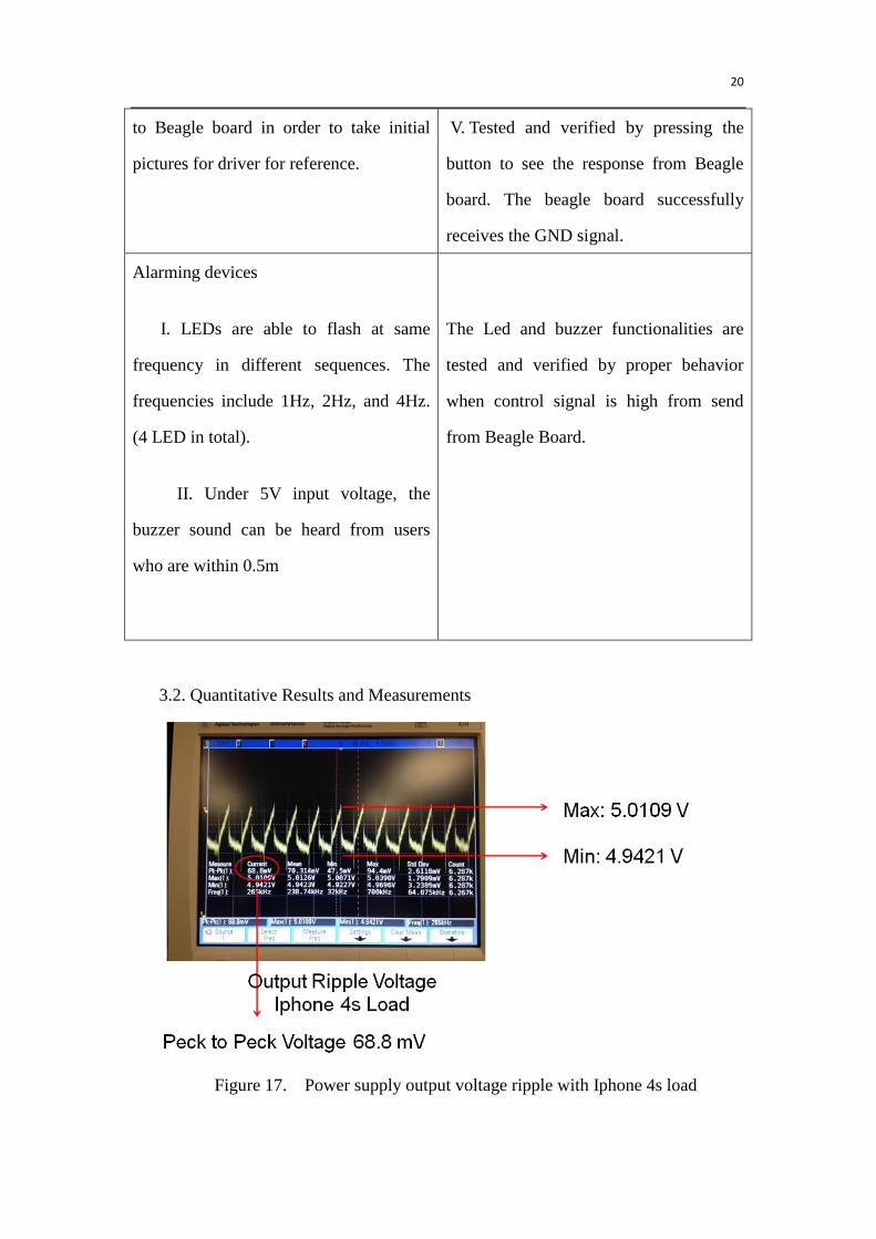
3.2. Quantitative Results and Measurements
Figure 17. Power supply output voltage ripple with Iphone 4s load
21
The figure 17 shows the voltage ripple measurement of dc-dc converter
output while charging a Iphone 4S device. The maximum and minimum
values indicate that ripple variance is within 10% range. The current draw is
0.43A.
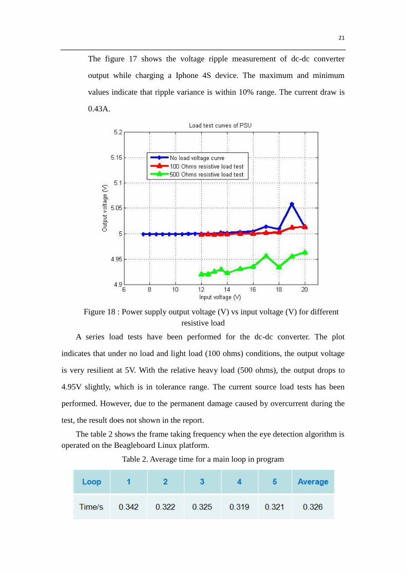
Figure 18 : Power supply output voltage (V) vs input voltage (V) for different
resistive load
A series load tests have been performed for the dc-dc converter. The plot
indicates that under no load and light load (100 ohms) conditions, the output voltage
is very resilient at 5V. With the relative heavy load (500 ohms), the output drops to
4.95V slightly, which is in tolerance range. The current source load tests has been
performed. However, due to the permanent damage caused by overcurrent during the
test, the result does not shown in the report.
The table 2 shows the frame taking frequency when the eye detection algorithm is
operated on the Beagleboard Linux platform.
Table 2. Average time for a main loop in program
22
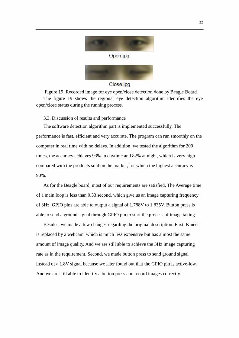
Figure 19. Recorded image for eye open/close detection done by Beagle Board
The figure 19 shows the regional eye detection algorithm identifies the eye
open/close status during the running process.
3.3. Discussion of results and performance
The software detection algorithm part is implemented successfully. The
performance is fast, efficient and very accurate. The program can run smoothly on the
computer in real time with no delays. In addition, we tested the algorithm for 200
times, the accuracy achieves 93% in daytime and 82% at night, which is very high
compared with the products sold on the market, for which the highest accuracy is
90%.
As for the Beagle board, most of our requirements are satisfied. The Average time
of a main loop is less than 0.33 second, which give us an image capturing frequency
of 3Hz. GPIO pins are able to output a signal of 1.788V to 1.835V. Button press is
able to send a ground signal through GPIO pin to start the process of image taking.
Besides, we made a few changes regarding the original description. First, Kinect
is replaced by a webcam, which is much less expensive but has almost the same
amount of image quality. And we are still able to achieve the 3Hz image capturing
rate as in the requirement. Second, we made button press to send ground signal
instead of a 1.8V signal because we later found out that the GPIO pin is active-low.
And we are still able to identify a button press and record images correctly.
23
4. Cost
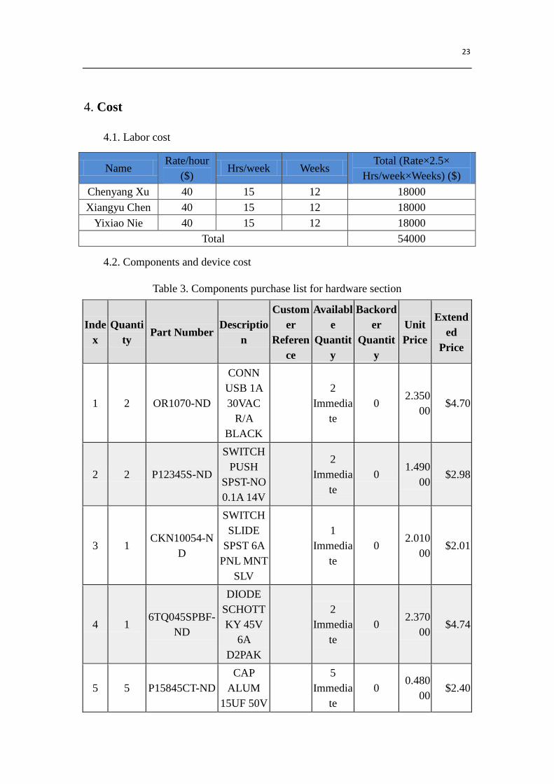
4.1. Labor cost
Name Rate/hour
($) Hrs/week Weeks
Total (Rate×2.5×
Hrs/week×Weeks) ($)
Chenyang Xu 40 15 12 18000
Xiangyu Chen 40 15 12 18000
Yixiao Nie 40 15 12 18000
Total 54000
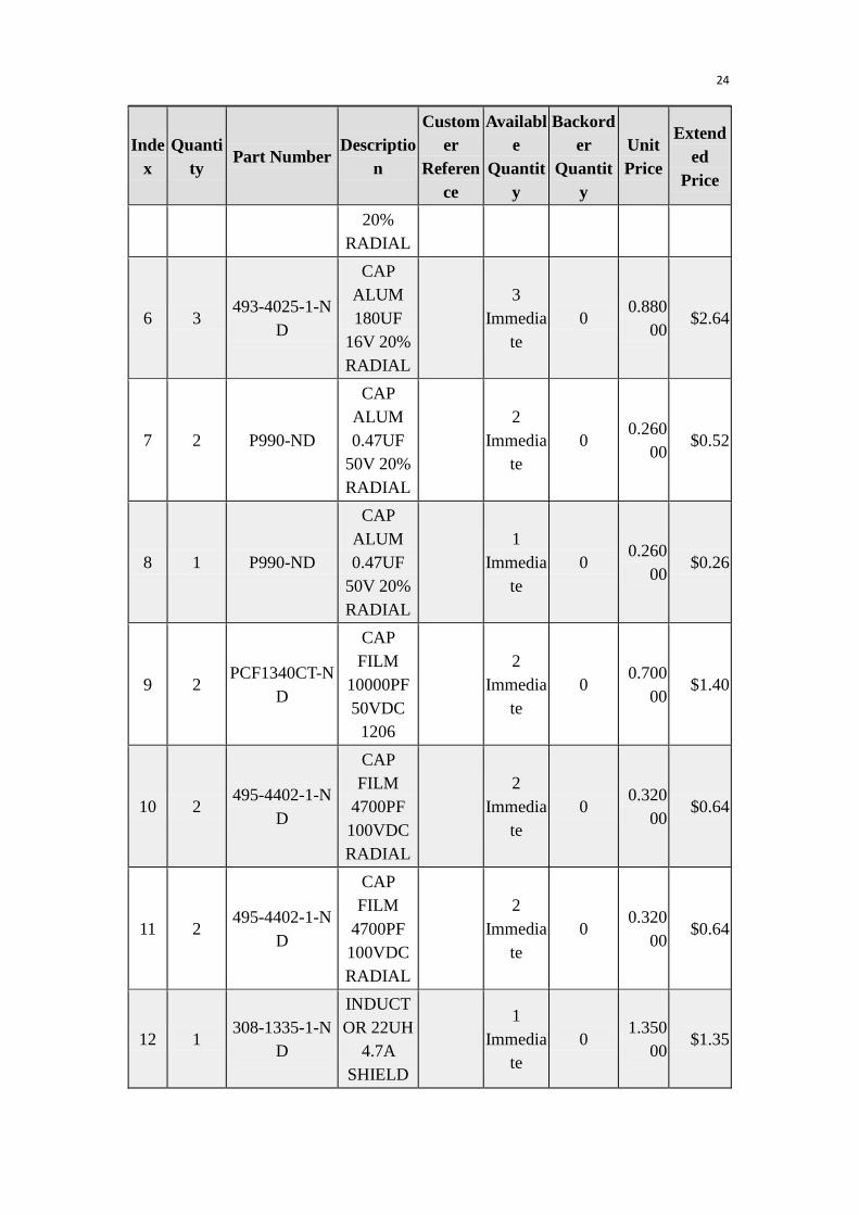
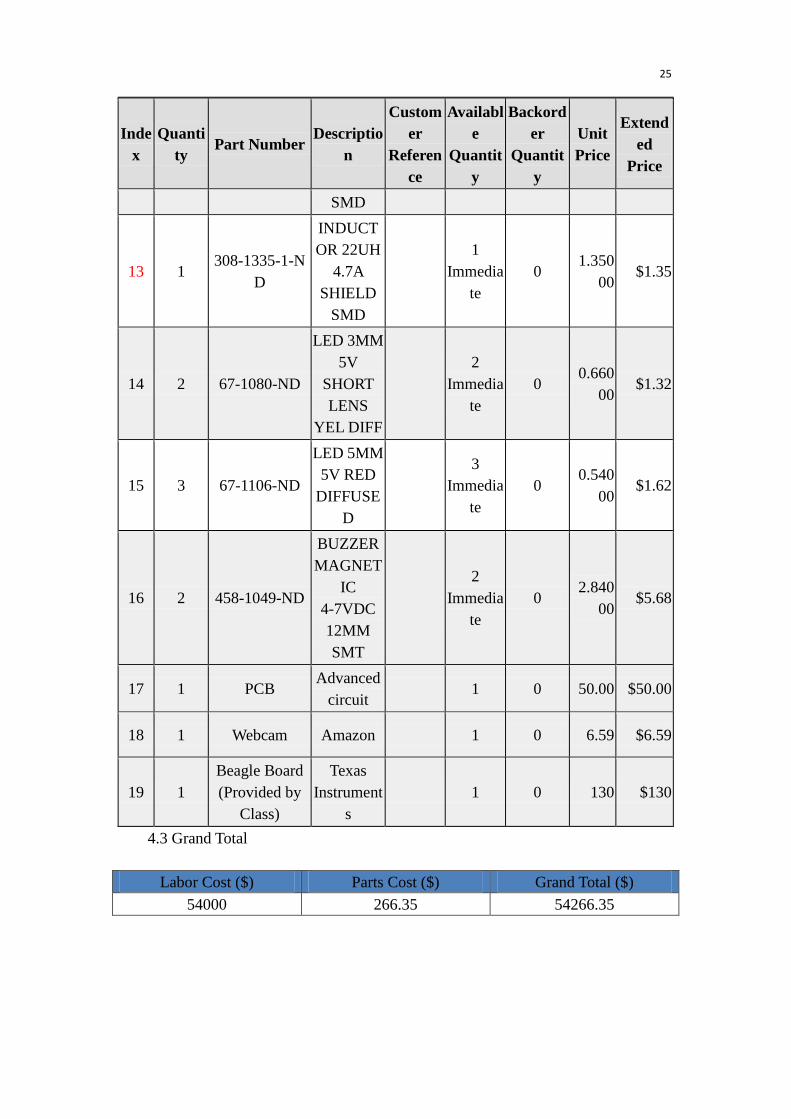
4.2. Components and device cost
Table 3. Components purchase list for hardware section
Inde
x
Quanti
ty Part Number
Descriptio
n
Custom
er
Referen
ce
Availabl
e
Quantit
y
Backord
er
Quantit
y
Unit
Price
Extend
ed
Price
1 2 OR1070-ND
CONN
USB 1A
30VAC
R/A
BLACK
2
Immedia
te
0 2.350
00 $4.70
2 2 P12345S-ND
SWITCH
PUSH
SPST-NO
0.1A 14V
2
Immedia
te
0 1.490
00 $2.98
3 1 CKN10054-N
D
SWITCH
SLIDE
SPST 6A
PNL MNT
SLV
1
Immedia
te
0 2.010
00 $2.01
4 1 6TQ045SPBF-
ND
DIODE
SCHOTT
KY 45V
6A
D2PAK
2
Immedia
te
0 2.370
00 $4.74
5 5 P15845CT-ND
CAP
ALUM
15UF 50V
5
Immedia
te
0 0.480
00 $2.40
24
Inde
x
Quanti
ty Part Number
Descriptio
n
Custom
er
Referen
ce
Availabl
e
Quantit
y
Backord
er
Quantit
y
Unit
Price
Extend
ed
Price
20%
RADIAL
6 3 493-4025-1-N
D
CAP
ALUM
180UF
16V 20%
RADIAL
3
Immedia
te
0 0.880
00 $2.64
7 2 P990-ND
CAP
ALUM
0.47UF
50V 20%
RADIAL
2
Immedia
te
0 0.260
00 $0.52
8 1 P990-ND
CAP
ALUM
0.47UF
50V 20%
RADIAL
1
Immedia
te
0 0.260
00 $0.26
9 2 PCF1340CT-N
D
CAP
FILM
10000PF
50VDC
1206
2
Immedia
te
0 0.700
00 $1.40
10 2 495-4402-1-N
D
CAP
FILM
4700PF
100VDC
RADIAL
2
Immedia
te
0 0.320
00 $0.64
11 2 495-4402-1-N
D
CAP
FILM
4700PF
100VDC
RADIAL
2
Immedia
te
0 0.320
00 $0.64
12 1 308-1335-1-N
D
INDUCT
OR 22UH
4.7A
SHIELD
1
Immedia
te
0 1.350
00 $1.35
25
Inde
x
Quanti
ty Part Number
Descriptio
n
Custom
er
Referen
ce
Availabl
e
Quantit
y
Backord
er
Quantit
y
Unit
Price
Extend
ed
Price
SMD
13 1 308-1335-1-N
D
INDUCT
OR 22UH
4.7A
SHIELD
SMD
1
Immedia
te
0 1.350
00 $1.35
14 2 67-1080-ND
LED 3MM
5V
SHORT
LENS
YEL DIFF
2
Immedia
te
0 0.660
00 $1.32
15 3 67-1106-ND
LED 5MM
5V RED
DIFFUSE
D
3
Immedia
te
0 0.540
00 $1.62
16 2 458-1049-ND
BUZZER
MAGNET
IC
4-7VDC
12MM
SMT
2
Immedia
te
0 2.840
00 $5.68
17 1 PCB Advanced
circuit 1 0 50.00 $50.00
18 1 Webcam Amazon 1 0 6.59 $6.59
19 1
Beagle Board
(Provided by
Class)
Texas
Instrument
s
1 0 130 $130
4.3 Grand Total
Labor Cost ($) Parts Cost ($) Grand Total ($)
54000 266.35 54266.35

26
5. Conclusion
5.1. Accomplishments
As for the software part, we fulfilled our goal successfully. The detection
algorithm could not only work effectively and accurately at daytime, but also at night.
The Eye portion extraction is smooth and in real time with no delays on the computer.
In addition, there is a bonus function in the software part – detection with glasses.
For the Beagleboard, we achieved two major difficulties. First, we were not able
to power up the board with any commercial chargers initially, including the ones for
Iphone, for Samsume, or the USB charger on car. But later we added DXPOWER
battery to power our board and used the power supply we designed to charge the
battery to solve the problem. Second, we experienced a few difficulties while
installing the OpenCV library on Beagleboard, but were able to solve it by changing
flags in makefiles to the one corresponding to ARM board architecture. The power
supply unit basically completes all its design requirements. By adding the extra USB
battery stage, the problem of powering the entire microcontroller and alarming system
has been solved. Moreover, the alarming system works as we supposed. The voltage
ripple of the power supply unit can be mitigated by applying more resilient capacitor
components.
It is apparent that the overall project success is not derived from one team
member’s mind but the keen coloration within our group. Each part is indispensable
and every team member made the great dedication on the completion of this design
project. The pace is intense, the learning, immense.
5.2 Ethnical consideration
1. to accept responsibility in making decisions consistent with the safety, health, and
welfare of the public, and to disclose promptly factors that might endanger the public
or the environment [5];
By using our Driver Sleep Detection and Alarming System, customers would be
warned when his/her physical condition is not good enough for driving and thus

27
prevents dangerous behaviors from happening. It is consistent with the safety and
welfare of the public.
5. to improve the understanding of technology; its appropriate application, and
potential consequences;
By using openCV and related libraries, we try to develop and improve algorithm
for eye closeness detecting. We then apply this technology to our application in order
to help drivers achieve a better and safer driving condition.
7. to seek, accept, and offer honest criticism of technical work, to acknowledge and
correct errors, and to credit properly the contributions of others;
We consult Professor and TAs for review advices and improve, seek online
resources to help correcting errors, and properly cite the contributions of other people.
9. to avoid injuring others, their property, reputation, or employment by false or
malicious action;
We design our product using qualified components and follow proper safety rules,
avoid wrong actions happening to other people.
5.3. Future work
1. Use OpenGL to control the frame rate more accurately
2. To achieve a higher accuracy at night
3. Use parallel programming such as CUDA to make code faster and more
efficient
4. Use bash script to enable our program to auto start after booting.
5. Use parallel programming and multi thread to handle image capturing,
sending control signal, and running algorithm separately.
6. Design hardware enclosure for PCB , microcontroller and USB battery
7. Use more advanced components in out/in capacitors to reduce the voltage

28
ripple of the output voltage
5.4. Uncertainty
The precision of night vision detection has some spaces to improve due to the
algorithm and hardware ability limitation. The accuracy of the algorithm needs
further optimization for the night condition.
29
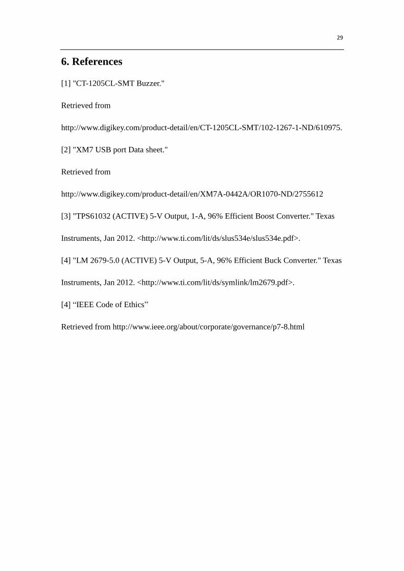
6. References
[1] "CT-1205CL-SMT Buzzer."
Retrieved from
http://www.digikey.com/product-detail/en/CT-1205CL-SMT/102-1267-1-ND/610975.
[2] "XM7 USB port Data sheet."
Retrieved from
http://www.digikey.com/product-detail/en/XM7A-0442A/OR1070-ND/2755612
[3] "TPS61032 (ACTIVE) 5-V Output, 1-A, 96% Efficient Boost Converter." Texas
Instruments, Jan 2012. <http://www.ti.com/lit/ds/slus534e/slus534e.pdf>.
[4] "LM 2679-5.0 (ACTIVE) 5-V Output, 5-A, 96% Efficient Buck Converter." Texas
Instruments, Jan 2012. <http://www.ti.com/lit/ds/symlink/lm2679.pdf>.
[4] “IEEE Code of Ethics”
Retrieved from http://www.ieee.org/about/corporate/governance/p7-8.html
30
7. Appendix