Embed Size (px)
Citation preview
Driver Board for XPS Controller and Piezoelectric Stages
User’s Manual
XPS-DRVP1
XPS-DRVP1
EDH0259En1010 – 08/10 ii
Warranty
Newport Corporation warrants this product to be free from defects in material and workmanship for a period of 1 year from the date of shipment. If found to be defective during the warranty period, the product will either be repaired or replaced at Newport’s discretion. To exercise this warranty, write or call your local Newport representative, or contact Newport headquarters in Irvine, California. You will be given prompt assistance and return instructions. Send the instrument, transportation prepaid, to the indicated service facility. Repairs will be made and the instrument returned, transportation prepaid. Repaired products are warranted for the balance of the original warranty period, or at least 90 days.
Limitation of Warranty This warranty does not apply to defects resulting from modification or misuse of any product or part.
CAUTION Warranty does not apply to damages resulting from: 1. Incorrect usage:
o With a non-Newport XPS controller. o Improper connection and grounding.
Connectors must be properly secured. Use of extension cables without Newport agreement. When the load on the stage presents an electrical risk, it must be
connected to ground. 2. Modification of the board or any part therein.
THIS WARRANTY IS IN LIEU OF ALL OTHER WARRANTIES, EXPRESSED OR IMPLIED, INCLUDING ANY IMPLIED WARRANTY OF MERCHANTABILITY OR FITNESS FOR A PARTICULAR USE. NEWPORT CORPORATION SHALL NOT BE LIABLE FOR ANY INDIRECT, SPECIAL, OR CONSEQUENTIAL DAMAGES. First printing 2010 Copyright 2010 by Newport Corporation, Irvine, CA. All rights reserved. No part of this manual may be reproduced or copied without the prior written approval of Newport Corporation. This manual is provided for information only, and product specifications are subject to change without notice. Any change will be reflected in future printings.
XPS-DRVP1
iii EDH0259En1010 – 08/10
Table of Contents
Warranty .......................................................................................................................................ii Definitions and Symbols ............................................................................................................iv Warning ........................................................................................................................................v Cautions ......................................................................................................................................vii
1.0 Introduction.......................................................................................... 1
2.0 Overview of piezoelectric technology .................................................. 2 2.1 Actuator principle ..................................................................................................................2 2.2 Actuator travel range .............................................................................................................2 2.3 Stages principle .........................................................................Erreur ! Signet non défini. 2.4 Position sensors ......................................................................................................................3 2.5 Piezoelectric technology pros and cons ................................................................................4
3.0 Newport solution advantages............................................................... 4 3.1 Control loops ..........................................................................................................................4
3.1.1 Open loop..............................................................................................................5 3.1.2 Close loop control ................................................................................................6
4.0 Specifications........................................................................................ 8 4.1 XPS-DRVP1 Functional description ....................................................................................8 4.2 XPS-DRVP1 Specifications ..................................................................................................8
5.0 Starting up............................................................................................ 9 5.1 Installing the XPS-DRVP1 in the XPS controller ...............................................................9 5.2 Stage connection ....................................................................................................................9 5.3 Powering up..........................................................................................................................10
5.3.1 XPS Controller ...................................................................................................10 5.3.2 Axis initialization ...............................................................................................10 5.3.3 Axial Load verification ......................................................................................11
6.0 Offset adjustment procedure ............................................................. 13
7.0 Accuracy linear correction procedure............................................... 15
8.0 Description/Use of « BNC » output.................................................... 17
XPS-DRVP1
EDH0259En1010 – 08/10 iv
9.0 Specific APIs....................................................................................... 18
10.0 Parameters description ...................................................................... 18 10.1 « System.ini» File ................................................................................................................18 10.2 « Stages.ini» File..................................................................................................................19
11.0 Maintenance ....................................................................................... 20 11.1 Axis initialization after error ...............................................................................................20 11.2 Maintenance .........................................................................................................................21 11.3 Repair....................................................................................................................................21
Service Form.................................................................................................... 23
XPS-DRVP1
v EDH0259En1010 – 08/10
Definitions and Symbols
The following terms and symbols are used in this documentation and also appear on the product where safety-related issues occur.
General Warning or Caution
The exclamation symbol may appear in warning and caution tables in this document. This symbol designates an area where personal injury or damage to the equipment is possible.
European Union CE Mark
The presence of the CE Mark on Newport Corporation equipment means that it has been designed, tested and certified as complying with all applicable European Union (CE) regulations and recommendations.
ATTENTION This board is designed to be used ONLY inside a Newport XPS controller. Proper installation procedure must be followed to ensure CE Mark compliance.
Warnings and Cautions The following are definitions of the Warnings, Cautions and Notes that may be used in this manual to call attention to important information regarding personal safety, safety and preservation of the equipment, or important tips.
WARNING Situation has the potential to cause bodily harm or death.
CAUTION Situation has the potential to cause damage to property or equipment.
NOTE Additional information the user or operator should consider.
XPS-DRVP1
EDH0259En1010 – 08/10 vi
Warning
WARNING Do not attempt to modify this board; this may cause an electric shock or downgrade its performance.
WARNING This product, like all microcontroller products, uses semiconductors that can be damaged by electrostatic discharge (ESD). When handling, care must be taken so that the devices are not damaged. Damage due to inappropriate handling is not covered by the warranty.
Cautions
CAUTION As Newport piezoelectric stages might include flexure mechanisms with limited load capacity, do not move the moving part of the stage manually.
CAUTION Do not disconnect the stage cable when the XPS controller is powered ON.

XPS-DRVP1
1 EDH0259En1010 – 08/10
XPS-DRVP1
1.0 Introduction This manual describes the operating instructions for the XPS-DRVP1driver board.
XPS-DRVP1 Driver board.
Newport « XPS-DRVP1 » driver board has been specially designed to provide POWERFUL and SIMPLE CONTROL, through XPS controller, of Newport stages motorized by piezoelectric actuators from the following series: NPA, NPM, NPO, NPX, NPXY, NPXY and PSM.
RECOMMENDATION You must read the chapter 5 “Installing the XPS-DRVP1 in the XPS controller ” carefully before attempting to use the XPS-DRVP1 driver board.
XPS Internal
connector
Position sensor feedback
monitoring Connector
(BNC)
Stage cable connector (Sub-
D 25 Pins)
XPS-DRVP1
EDH0259En1010 – 08/10 2
2.0 Overview of piezoelectric technology
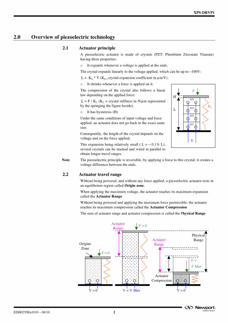
2.1 Actuator principle A piezoelectric actuator is made of crystals (PZT: Plumbium Zirconate Titanate) having three properties: o It expands whenever a voltage is applied at the ends. The crystal expands linearly to the voltage applied, which can be up to ~100V: �L = KE * V (KE = crystal expansion coefficient in µm/V). o It shrinks whenever a force is applied on it. The compression of the crystal also follows a linear law depending on the applied force: �L = F / KC (KC = crystal stiffness in N/µm represented by the springing the figure beside). o It has hysteresis (H) Under the same conditions of input voltage and force applied, an actuator does not go back to the exact same size. Consequently, the length of the crystal depends on the voltage and on the force applied. This expansion being relatively small (�L = ~ 0.1% L), several crystals can be stacked and wired in parallel to obtain longer travel ranges.
Note: The piezoelectric principle is reversible, by applying a force to this crystal; it creates a voltage difference between the ends.
2.2 Actuator travel range Without being powered, and without any force applied, a piezoelectric actuator rests in an equilibrium region called Origin zone. When applying the maximum voltage, the actuator reaches its maximum expansion called the Actuator Range Without being powered and applying the maximum force permissible, the actuator reaches its maximum compression called the Actuator Compression The sum of actuator range and actuator compression is called the Physical Range
F
L
V
KC
H PZT
PZT
PZT
PZT
F = 0
V = 0
OrigineZone
F = 0
V = V Max
Actuator Range
F = F Max
V = 0
Actuator Compression
PhysicalRange Actuator
Range

XPS-DRVP1
3 EDH0259En1010 – 08/10
2.3 Piezoelectric Stages Two types of stages use piezoelectric actuators: o Direct: No mechanism is
added, the crystal directly « pushes » the moving part (i.e. : actuator)
o Amplified: the crystal pushes the mobile part decoupled from the base by flexures.
The motion can be amplified by lever arms shown below (i.e. : NPX stages)
Note: The design o f the stage mechanism is important to minimize the motion in the orthogonal dimension (�y) which can be neglected.
2.4 Position sensors Stages can be equipped with position sensors of the
“strain gauge” type which is made of thin metallic conductors (few µm thick) placed on a non-conductive material.
Expansion of the conductors changes electrical resistance following a linear law:
(�R / R = Kj * �L / L) The relative displacement measured at the strain gauge
is directly proportional to the stage mobile part displacement and so provides position information.
The sensor’s range is greater than the full physical range of the stage.
R
L
�L
�y
Base
Moving Part
PZT
Physical range
Centered Load
Axial Load
Actuator range
PZT
Base
Moving Part
Physical range
Centered Load
Axial Load
F = 0
V = 0
Origin Zone
F = 0
V = V Max
F = F Max
V = 0
Sensor Range
PhysicalRange
Sensor Scale
Sensor Scale
Sensor Scale
RMIN
RMAX
R0
Actuator Range
XPS-DRVP1
EDH0259En1010 – 08/10 4
2.5 Piezoelectric technology pros and cons Stages using piezoelectric technology usually have a relatively small footprint and offer high sensitivity (nanometer level) combined with fast motion (frequency of several hundreds Hertz for actuators). Position can be controlled simply in open loop by providing a voltage to the actuator (~0 to 100V), but hysteresis can reach up to 10% of the range. “Direct” type of stages offers a short range (few hundred microns) with high axial load capacity (several tens of kilograms) and good axial stiffness (several tens of N/µm) “Amplified” type of stages offers longer range but drastically reduced axial load capacity (kilogram level) and axial stiffness (N/µm level). Stages equipped with position sensors allow hysteresis compensation but requires close loop control mode. Higher absolute accuracy can be obtained but requires stage calibration using an external device.
3.0 Newport solution advantages Newport piezoelectric actuators and stages controlled through the XPS controller and the XPS-DRVP1 driver board provide simple efficient solutions for a wide variety of applications from fast positioning with high resolution to fast signal tracking and to true high resolution/accuracy absolute positioning. All Newport piezoelectric stages are tested and calibrated in the factory. Calibration parameters like: piezoelectric actuator input voltage range, stage range, sensor (if present) position and resolution, etc. are loaded into the stage’s EEPROM. During initialization, the XPS controller and the XPS-DRVP1 driver boards read these parameters and automatically configure the axis for optimum control (open / close loop, resolution, range, etc.) The stage can then be used like any motorized stage with origin position, software limits, relative and absolute moves, etc. XPS-DRVP1 driver board also features a position sensor feedback analog signal output providing precise stage real position information. See chapter: « BNC » output Newport solution also allows sensor calibration to improve the stage absolute accuracy. See chapter: Accuracy linear correction.
3.1 Control loops After power-on and during initialization, the XPS controller through the XPS-DRVP1 driver board reads the parameters from the connected stage and sets the corresponding control loop type: o Without sensor (i.e. NPX400-D, NPXY200-D, etc.) : Open loop control o With sensor (i.e. NPX400SG-D, NPXY200SG-D, etc.) : Close loop control
XPS-DRVP1
5 EDH0259En1010 – 08/10
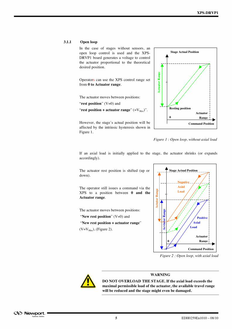
3.1.1 Open loop In the case of stages without sensors, an open loop control is used and the XPS-DRVP1 board generates a voltage to control the actuator proportional to the theoretical desired position. Operators can use the XPS control range set from 0 to Actuator range. The actuator moves between positions: “rest position” (V=0) and “rest position + actuator range” (=VMax)”. However, the stage’s actual position will be affected by the intrinsic hysteresis shown in Figure 1.
Figure 1 : Open loop, without axial load
If an axial load is initially applied to the stage, the actuator shrinks (or expands accordingly). The actuator rest position is shifted (up or down). The operator still issues a command via the XPS to a position between 0 and the Actuator range. The actuator moves between positions: “New rest position” (V=0) and “New rest position + actuator range” (V=VMax), (Figure 2).
Figure 2 : Open loop, with axial load
WARNING DO NOT OVERLOAD THE STAGE. If the axial load exceeds the maximal permissible load of the actuator, the available travel range will be reduced and the stage might even be damaged.
Command Position
Stage Actual Position
0
Act
uato
r R
ange
Actuator Range
Resting position
Command Position
Stage Actual Position
0
Acv
tuto
r R
ange
Act
utor
Ran
ge
Negative Axial Load
Positive Axial Load
Actuator Range
XPS-DRVP1
EDH0259En1010 – 08/10 6
3.1.2 Close loop control For stages equipped with a strain gage sensor, the XPS controller and XPS-DRVP1 board allow true absolute positioning by generating the necessary voltage to the actuator to maintain the desired absolute position based on the sensor scale. At power-on and during initialization, the stage usable range, corresponding control voltage, sensor origin and current positions are read from the stage EEPROM and are used to set the necessary driver board closed loop parameters and also the XPS control range at 80% of the open loop actuator range. As described in the Actuator travel range chapter, modifying the stage axial load will shift the actual stage travel range within its physical range. Three cases can be considered: o Without any axial load a Newport piezoelectric stage resting position is very close
to its sensor origin position and the Default configuration can be used. o With a small variation of the axial load the resting position is slightly shifted
causing a stage Usable range limitation o In the case of a high axial load, although the actuator range is shifted along the
sensor absolute scale and the usable range is reduced, the XPS controller allows Full range recovery and maintains the same origin. This is done by setting the « DriverStagePositionOffset » (DSPO) parameter.
3.1.2.1 Default configuration
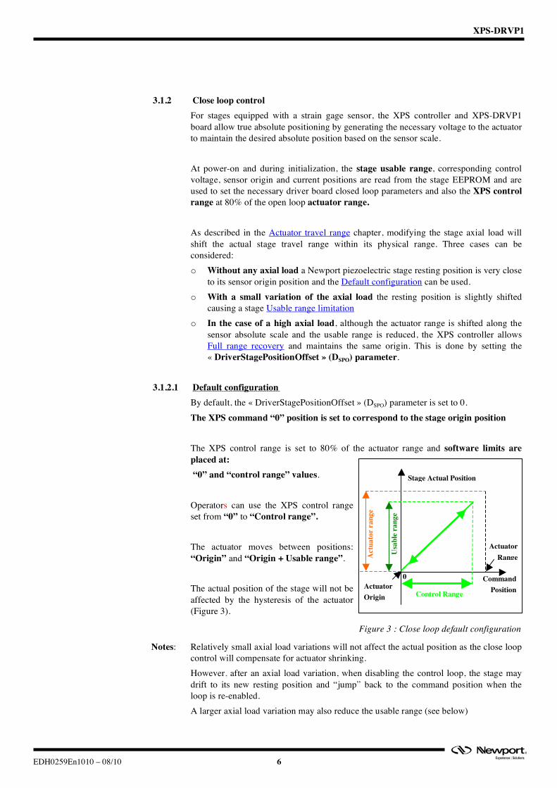
By default, the « DriverStagePositionOffset » (DSPO) parameter is set to 0. The XPS command “0” position is set to correspond to the stage origin position The XPS control range is set to 80% of the actuator range and software limits are placed at: “0” and “control range” values. Operators can use the XPS control range set from “0” to “Control range”. The actuator moves between positions: “Origin” and “Origin + Usable range”. The actual position of the stage will not be affected by the hysteresis of the actuator (Figure 3).
Figure 3 : Close loop default configuration
Notes: Relatively small axial load variations will not affect the actual position as the close loop control will compensate for actuator shrinking. However, after an axial load variation, when disabling the control loop, the stage may drift to its new resting position and “jump” back to the command position when the loop is re-enabled. A larger axial load variation may also reduce the usable range (see below)
Stage Actual Position
Usa
ble
rang
e
Command Position
Actuator Range
Actuator Origin Control Range
Act
uato
r ra
nge
0
XPS-DRVP1
7 EDH0259En1010 – 08/10
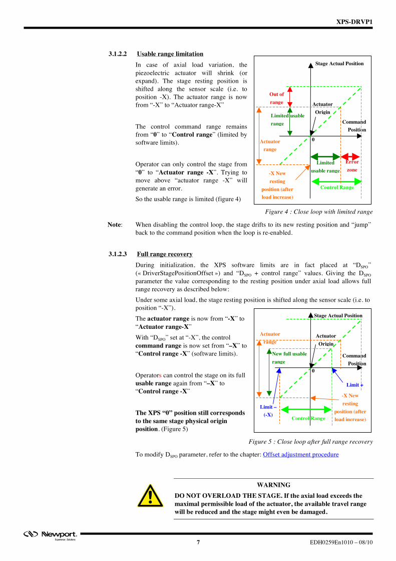
3.1.2.2 Usable range limitation In case of axial load variation, the piezoelectric actuator will shrink (or expand). The stage resting position is shifted along the sensor scale (i.e. to position -X). The actuator range is now from “-X” to “Actuator range-X” The control command range remains from “0” to “Control range” (limited by software limits). Operator can only control the stage from “0” to “Actuator range -X”. Trying to move above “actuator range -X” will generate an error. So the usable range is limited (figure 4)
Figure 4 : Close loop with limited range
Note: When disabling the control loop, the stage drifts to its new resting position and “jump” back to the command position when the loop is re-enabled.
3.1.2.3 Full range recovery
During initialization, the XPS software limits are in fact placed at “DSPO” (« DriverStagePositionOffset ») and “DSPO + control range” values. Giving the DSPO parameter the value corresponding to the resting position under axial load allows full range recovery as described below: Under some axial load, the stage resting position is shifted along the sensor scale (i.e. to position “-X”). The actuator range is now from “-X” to “Actuator range-X” With “DSPO” set at “-X”, the control command range is now set from “–X” to “Control range -X” (software limits). Operators can control the stage on its full usable range again from “–X” to “Control range -X” The XPS “0” position still corresponds to the same stage physical origin position. (Figure 5)
Figure 5 : Close loop after full range recovery
To modify DSPO parameter, refer to the chapter: Offset adjustment procedure
WARNING DO NOT OVERLOAD THE STAGE. If the axial load exceeds the maximal permissible load of the actuator, the available travel range will be reduced and the stage might even be damaged.
-X New resting
position (after load increase)
Stage Actual Position
Command Position
Actuator Origin
0
Control Range
Limited usable range
Error zone
Out of range
Limited usable range
New resting position
(after load increase)
Actuator range
-X New resting
position (after load increase)
Stage Actual Position
Command Position
Actuator Origin
0
Control Range
New full usable range
New resting position
(after load increase)
Actuator range
Limit – (-X)
Limit +

XPS-DRVP1
EDH0259En1010 – 08/10 8
4.0 Specifications
4.1 XPS-DRVP1 Compatibility and Functional description Newport « XPS-DRVP1 » driver board has been specially designed to drive the following Newport piezoelectric actuators and stages:
Stage Series Without Position Sensor With Position Sensor
NPA25, NPA25V6 NPA25SG, NPA25SGV6 NPA50, NPA50V6 NPA50SG, NPA50SGV6 NPA
NPA100, NPA 00V6 NPA100SG, NPA100SGV6 NPC NPC3 NPC3SG
NPM NPM140 NPM180
NPM140SG NPM180SG
NPO NPO100 NPO140
NPO250, NPO250V6
NPO100SG NPO140SG
NPO250SG, NPO250SGV6
NPX NPX200, NPX200V6 NPX400
NPX200SG, NPX200SGV6 NPX400SG
NPXY NPXY100, NPXY100V6 NPXY200
NPXY100SG, NPXY100SGV6 NPXY200SG
NPXYZ NPXYZ100, NPXYZ100V6 NPXYZ100SG, NPXYZ100SGV6 PSM PSM2 PSM2SG
Figure 6 : XPS-DRVP1 compatibility list
After installation in the XPS controller, the XPS-DRVP1 board allows: o Automatic reading of stages parameters (stored during final testing in the factory) o Automatic setting of control loop type (open or closed loop) o Ensuring absolute positioning of the stage under different axial loads due to its
Range shifting function o Providing voltage information relative to the sensor position (if present in the
stage) through « BNC » connector
4.2 XPS-DRVP1 Specifications
Parameters Specifications Output Voltage -10V, + 130 V Resolution < 10 mV Max. Output Current 60mA BNC Output voltage 0 – 10V Internal Frequency 2 kHz
Figure 7 : XPS-DRVP1 Specifications
XPS-DRVP1
9 EDH0259En1010 – 08/10
5.0 Starting up
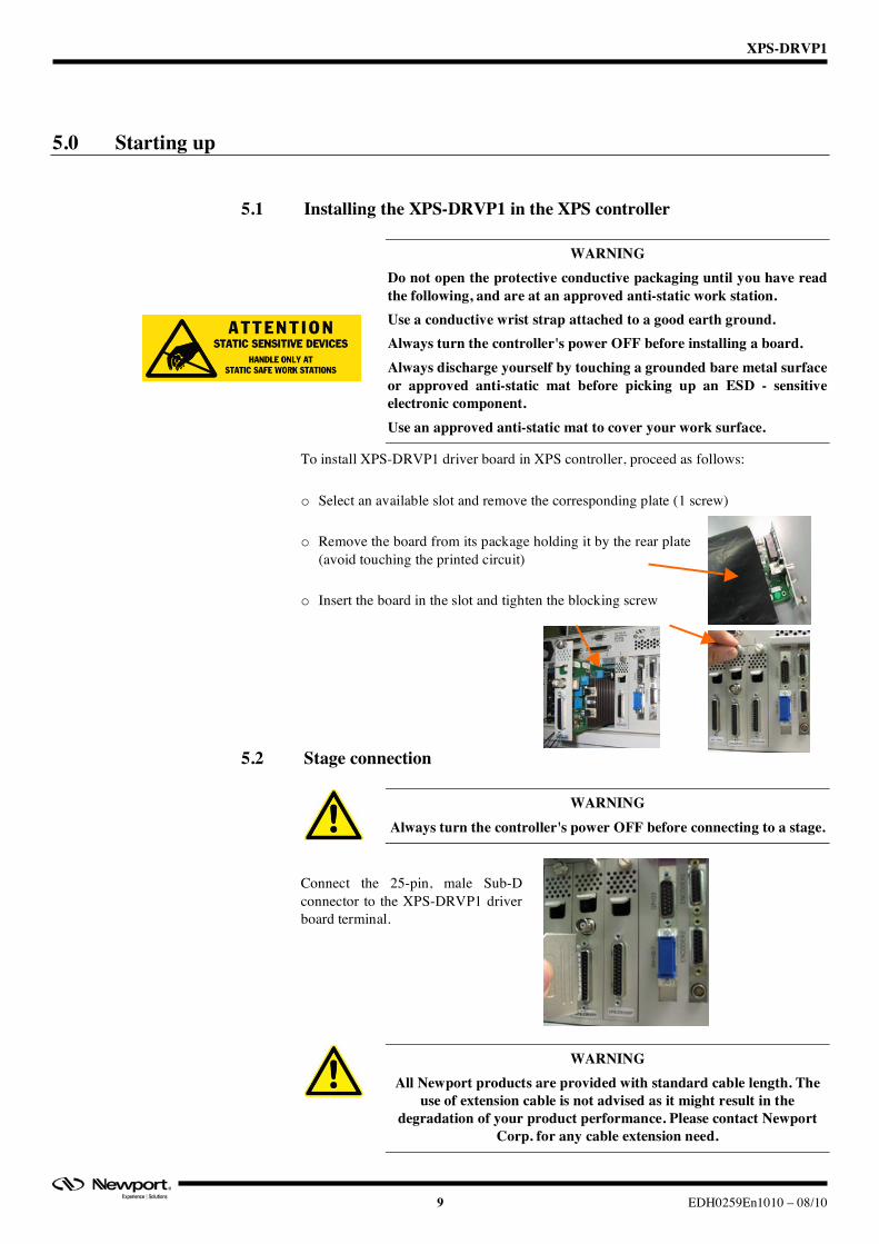
5.1 Installing the XPS-DRVP1 in the XPS controller
WARNING Do not open the protective conductive packaging until you have read the following, and are at an approved anti-static work station. Use a conductive wrist strap attached to a good earth ground. Always turn the controller's power OFF before installing a board. Always discharge yourself by touching a grounded bare metal surface or approved anti-static mat before picking up an ESD - sensitive electronic component. Use an approved anti-static mat to cover your work surface.
To install XPS-DRVP1 driver board in XPS controller, proceed as follows: o Select an available slot and remove the corresponding plate (1 screw) o Remove the board from its package holding it by the rear plate
(avoid touching the printed circuit) o Insert the board in the slot and tighten the blocking screw
5.2 Stage connection
WARNING Always turn the controller's power OFF before connecting to a stage.
Connect the 25-pin, male Sub-D connector to the XPS-DRVP1 driver board terminal.
WARNING All Newport products are provided with standard cable length. The
use of extension cable is not advised as it might result in the degradation of your product performance. Please contact Newport
Corp. for any cable extension need.
XPS-DRVP1
EDH0259En1010 – 08/10 10
5.3 Powering up After installing the XPS-DRVP1 board, the XPS controller can now be powered on. However, the presence of this new board requires updating the XPS controller initialization file « system.ini ». Then, after the correct parameter setting, the axis (driver board + stage without axial load) can be initialized. Finally, in case of a stage equipped with position sensor, verify the behaviour of the axis depending on the axial load place on the stage.
5.3.1 XPS Controller For instructions on how to update « system.ini » initialization file, refers to « Getting started/ configuring the controller » section of the XPS UserManual. (See also the File <<System.ini>> chapter for “system.ini” file example)
Note: If the new driver board and/or the stage are not automatically detected, the XPS
firmware might need to be updated manually. Refer to chapter 6.4 «Software Tools/Maintenance and Service » of the XPS « UserManual » documentation. Latest XPS firmware package can be downloaded from Newport ftp site at: ftp://download.newport.com/MotionControl/Current/MotionControllers/XPS/Updates/
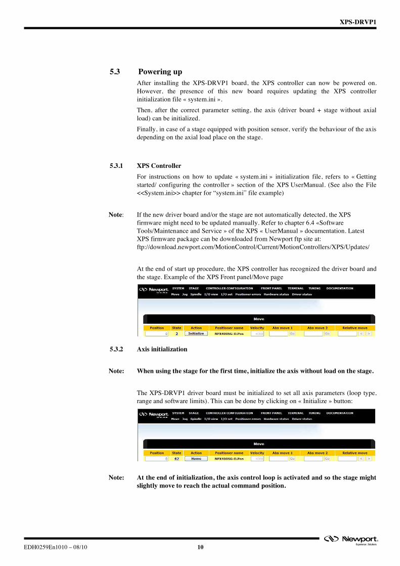
At the end of start up procedure, the XPS controller has recognized the driver board and the stage. Example of the XPS Front panel/Move page
5.3.2 Axis initialization
Note: When using the stage for the first time, initialize the axis without load on the stage.
The XPS-DRVP1 driver board must be initialized to set all axis parameters (loop type, range and software limits). This can be done by clicking on « Initialize » button:
Note: At the end of initialization, the axis control loop is activated and so the stage might slightly move to reach the actual command position.

XPS-DRVP1
11 EDH0259En1010 – 08/10
The axis must now be referenced by clicking on « Home » button: The axis is now ready to be used.
Note: A preset value can be set to the current position. See chapter: Offset adjustment procedure
5.3.3 Axial Load verification For stages equipped with a position sensor, the following tests can be performed to verify axis behavior based on an axial load.
5.3.3.1 No axial Load All Newport piezoelectric stages are tested and calibrated in the factory. Calibration parameters (saved in the stage’s EEPROM) allow the driver board to set the XPS controller scale Zero position at the stage origin. With no applied power, any Newport piezoelectric stage rests in an equilibrium or rest position based on actuator’s hysteresis. Although very close, this position is always slightly different from the stage origin (within 5% of the total travel range). The value at this rest position can be obtained using XPS Website « terminal » page.
Note: Axis must be disabled prior to using this command In the list, select the command: « PositionerDriverPositionOffsetsGet » then click on « OK » and finally « Execute » The command returns 3 numbers separated by comas: - The first “0” indicates the correct execution of the command.
- The second number indicates the current value (in microns) of the
« DriverStagePositionOffset » parameter of the « stages.ini » file. See chapter: Offset adjustment procedure. (Default value: “0”)
XPS-DRVP1
EDH0259En1010 – 08/10 12
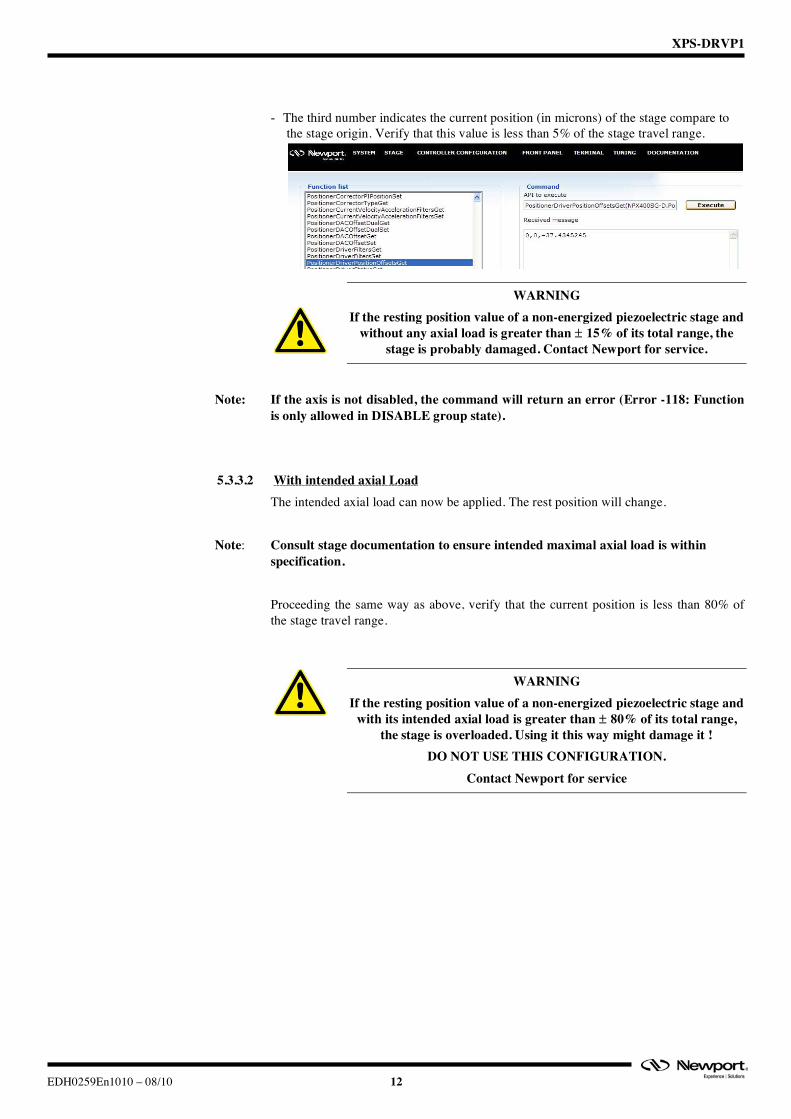
- The third number indicates the current position (in microns) of the stage compare to
the stage origin. Verify that this value is less than 5% of the stage travel range.
WARNING If the resting position value of a non-energized piezoelectric stage and
without any axial load is greater than ± 15% of its total range, the stage is probably damaged. Contact Newport for service.
Note: If the axis is not disabled, the command will return an error (Error -118: Function
is only allowed in DISABLE group state).
5.3.3.2 With intended axial Load The intended axial load can now be applied. The rest position will change.
Note: Consult stage documentation to ensure intended maximal axial load is within specification. Proceeding the same way as above, verify that the current position is less than 80% of the stage travel range.
WARNING If the resting position value of a non-energized piezoelectric stage and
with its intended axial load is greater than ± 80% of its total range, the stage is overloaded. Using it this way might damage it !
DO NOT USE THIS CONFIGURATION. Contact Newport for service
XPS-DRVP1
13 EDH0259En1010 – 08/10
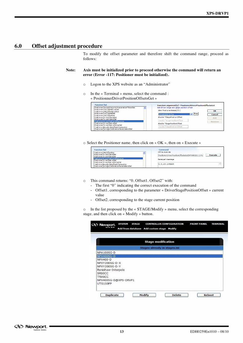
6.0 Offset adjustment procedure To modify the offset parameter and therefore shift the command range, proceed as follows:
Note: Axis must be initialized prior to proceed otherwise the command will return an error (Error -117: Positioner must be initialized).
o Logon to the XPS website as an “Administrator”
o In the « Terminal » menu, select the command :
« PositionnerDriverPositionOffsetsGet » o Select the Positioner name, then click on « OK », then on « Execute » o This command returns: “0, Offset1, Offset2” with:
- The first “0” indicating the correct execution of the command - Offset1, corresponding to the parameter « DriverStagePositionOffset » current
value - Offset2, corresponding to the stage current position
o In the list proposed by the « STAGE/Modify » menu, select the corresponding stage, and then click on « Modify » button.
XPS-DRVP1
EDH0259En1010 – 08/10 14
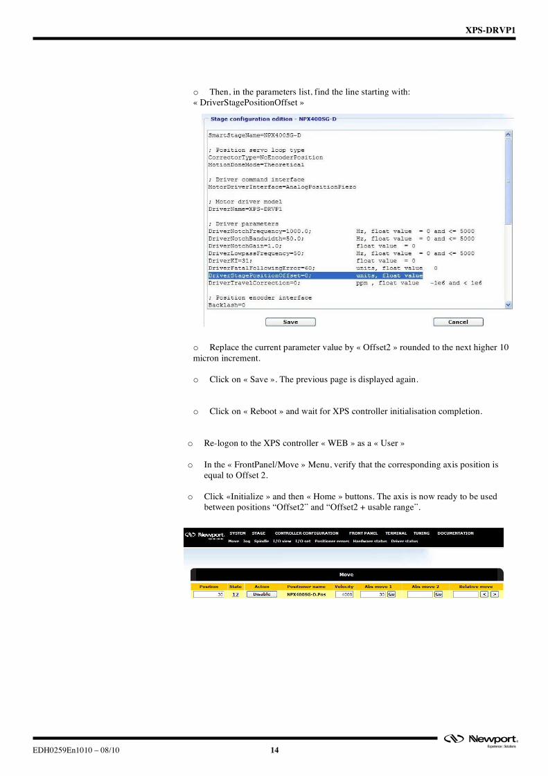
o Then, in the parameters list, find the line starting with: « DriverStagePositionOffset »
o Replace the current parameter value by « Offset2 » rounded to the next higher 10 micron increment.
o Click on « Save ». The previous page is displayed again.
o Click on « Reboot » and wait for XPS controller initialisation completion.
o Re-logon to the XPS controller « WEB » as a « User »
o In the « FrontPanel/Move » Menu, verify that the corresponding axis position is equal to Offset 2.
o Click «Initialize » and then « Home » buttons. The axis is now ready to be used
between positions “Offset2” and “Offset2 + usable range”.
XPS-DRVP1
15 EDH0259En1010 – 08/10
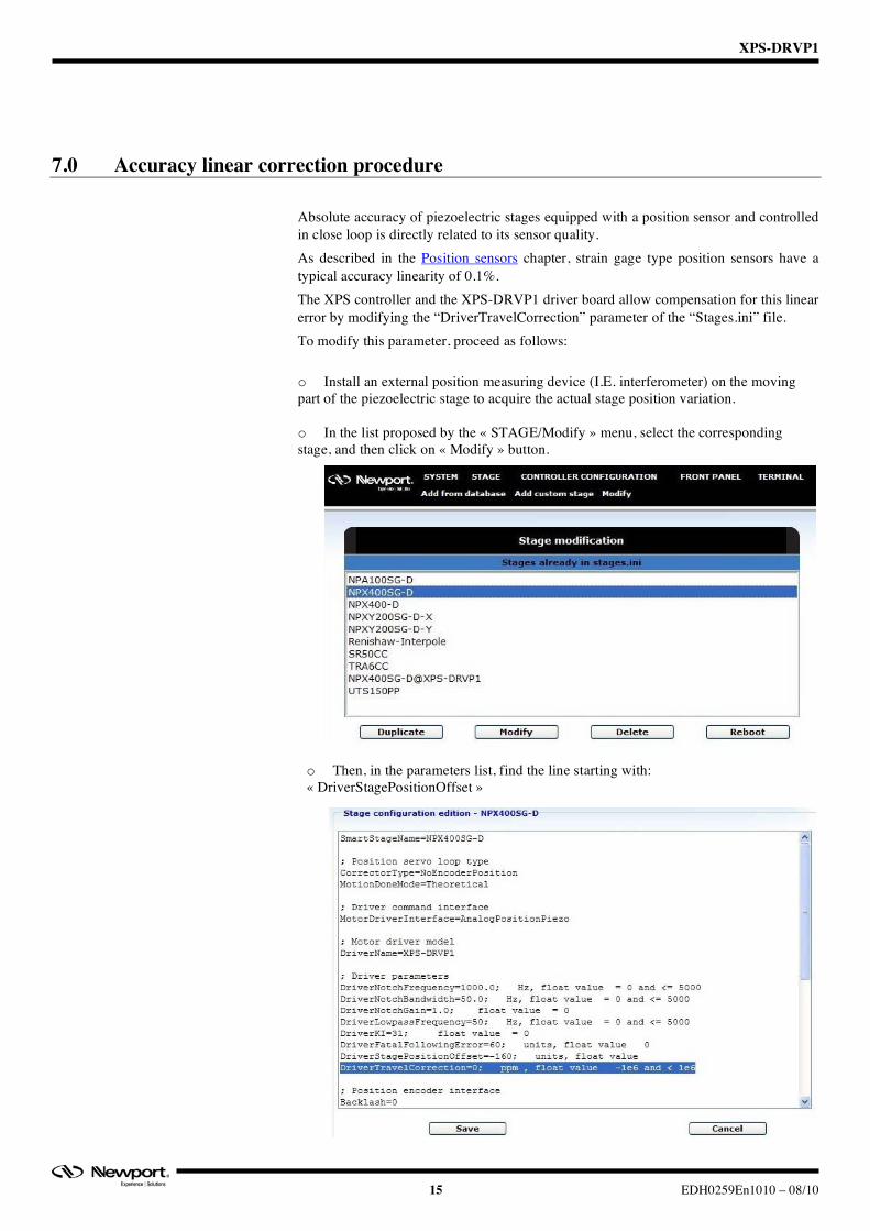
7.0 Accuracy linear correction procedure Absolute accuracy of piezoelectric stages equipped with a position sensor and controlled in close loop is directly related to its sensor quality. As described in the Position sensors chapter, strain gage type position sensors have a typical accuracy linearity of 0.1%. The XPS controller and the XPS-DRVP1 driver board allow compensation for this linear error by modifying the “DriverTravelCorrection” parameter of the “Stages.ini” file. To modify this parameter, proceed as follows: o Install an external position measuring device (I.E. interferometer) on the moving part of the piezoelectric stage to acquire the actual stage position variation.
o In the list proposed by the « STAGE/Modify » menu, select the corresponding stage, and then click on « Modify » button.
o Then, in the parameters list, find the line starting with: « DriverStagePositionOffset »
XPS-DRVP1
EDH0259En1010 – 08/10 16
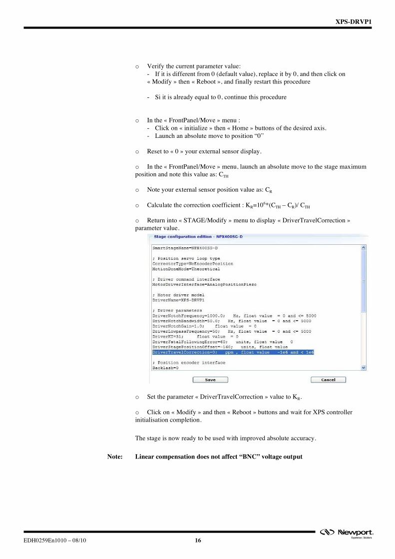
o Verify the current parameter value: - If it is different from 0 (default value), replace it by 0, and then click on « Modify » then « Reboot », and finally restart this procedure
- Si it is already equal to 0, continue this procedure
o In the « FrontPanel/Move » menu : - Click on « initialize » then « Home » buttons of the desired axis. - Launch an absolute move to position “0”
o Reset to « 0 » your external sensor display.
o In the « FrontPanel/Move » menu, launch an absolute move to the stage maximum position and note this value as: CTH
o Note your external sensor position value as: CR
o Calculate the correction coefficient : KR=106*(CTH – CR)/ CTH
o Return into « STAGE/Modify » menu to display « DriverTravelCorrection » parameter value.
o Set the parameter « DriverTravelCorrection » value to KR.
o Click on « Modify » and then « Reboot » buttons and wait for XPS controller initialisation completion.
The stage is now ready to be used with improved absolute accuracy.
Note: Linear compensation does not affect “BNC” voltage output
XPS-DRVP1
17 EDH0259En1010 – 08/10
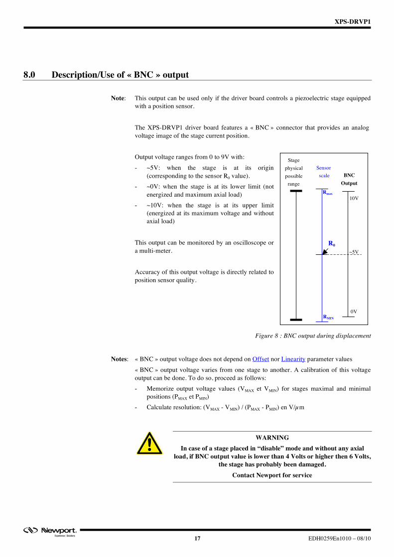
8.0 Description/Use of « BNC » output Note: This output can be used only if the driver board controls a piezoelectric stage equipped
with a position sensor.
The XPS-DRVP1 driver board features a « BNC » connector that provides an analog voltage image of the stage current position. Output voltage ranges from 0 to 9V with: - ~5V: when the stage is at its origin
(corresponding to the sensor R0 value). - ~0V: when the stage is at its lower limit (not
energized and maximum axial load) - ~10V: when the stage is at its upper limit
(energized at its maximum voltage and without axial load)
This output can be monitored by an oscilloscope or a multi-meter. Accuracy of this output voltage is directly related to position sensor quality.
Figure 8 : BNC output during displacement
Notes: « BNC » output voltage does not depend on Offset nor Linearity parameter values
« BNC » output voltage varies from one stage to another. A calibration of this voltage output can be done. To do so, proceed as follows: - Memorize output voltage values (VMAX et VMIN) for stages maximal and minimal
positions (PMAX et PMIN) - Calculate resolution: (VMAX - VMIN) / (PMAX - PMIN) en V/µm
WARNING In case of a stage placed in “disable” mode and without any axial
load, if BNC output value is lower than 4 Volts or higher then 6 Volts, the stage has probably been damaged.
Contact Newport for service
Stage physical possible
range
Sensor scale
RMIN
Rmax
R0
BNC Output
~5V
0V
10V
XPS-DRVP1
EDH0259En1010 – 08/10 18
9.0 Specific APIs In addition to the standard XPS commands, the following XPS-DRVP1 board specific APIs are available: - « PositionerDriverFiltersGet » : to get axis current close loop control parameters:
KI (close loop integral coefficient), Notch filter frequency, Notch filter bandwidth, Notch filter gain and Low Pass filter frequency
- « PositionerDriverFiltersSet » : to set axis closed loop control parameters - « PositionerDriverStatusGet » : to get driver board current status number - « PositionerDriverStatusStringGet » : to get driver board detailed status - « PositionnerDriverPositionOffsetsGet »: to get offset parameters (see Offset
adjustment procedure chapter)
10.0 Parameters description Parameters required to drive piezoelectric stages are preset in the factory within the system.ini and stages.ini files and some of these can be modified by the user. Examples of piezoelectric stage parameters:
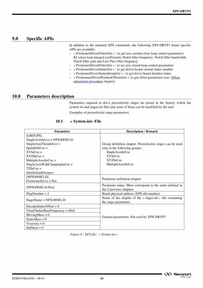
10.1 « System.ini» File
Paramètre Description / Remark [GROUPS] SingleAxisInUse = NPX400SG-D SingleAxisThetaInUse = SpindleInUse = XYInUse = XYZInUse = MultipleAxesInUse = SingleAxisWithClampingInUse = TZInUse = InterlockedGroups=
Group definition chapter. Piezoelectric stages can be used only in the following groups :
- SingleAxisInUse - XYInUse - XYZInUse - MultipleAxesInUse
[NPX400SG-D] PositionerInUse = Pos Positioner definition chapter
[NPX400SG-D.Pos] Positioner name. Must correspond to the name defined in the 2 previous chapters
PlugNumber = 2 Board physical address (XPS slot number)
StageName = NPX400SG-D Name of the chapter of the « stages.ini » file containing the stage parameters.
EncoderIndexOffset = 0 TimeFlasherBaseFrequency = 40e6 MovingMass = 0 StaticMass = 0 Viscosity = 0 Stiffness = 0
General parameters. Not used by XPS-DRVP1
Figure 9 : XPS file: « System.ini »
XPS-DRVP1
19 EDH0259En1010 – 08/10
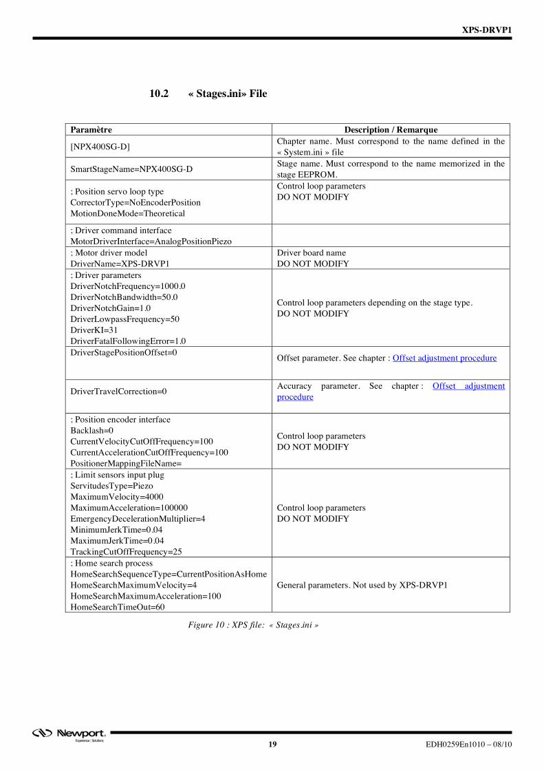
10.2 « Stages.ini» File
Paramètre Description / Remarque
[NPX400SG-D] Chapter name. Must correspond to the name defined in the « System.ini » file
SmartStageName=NPX400SG-D Stage name. Must correspond to the name memorized in the stage EEPROM.
; Position servo loop type CorrectorType=NoEncoderPosition MotionDoneMode=Theoretical
Control loop parameters DO NOT MODIFY
; Driver command interface MotorDriverInterface=AnalogPositionPiezo
; Motor driver model DriverName=XPS-DRVP1
Driver board name DO NOT MODIFY
; Driver parameters DriverNotchFrequency=1000.0 DriverNotchBandwidth=50.0 DriverNotchGain=1.0 DriverLowpassFrequency=50 DriverKI=31 DriverFatalFollowingError=1.0
Control loop parameters depending on the stage type. DO NOT MODIFY
DriverStagePositionOffset=0
Offset parameter. See chapter : Offset adjustment procedure
DriverTravelCorrection=0
Accuracy parameter. See chapter : Offset adjustment procedure
; Position encoder interface Backlash=0 CurrentVelocityCutOffFrequency=100 CurrentAccelerationCutOffFrequency=100 PositionerMappingFileName=
Control loop parameters DO NOT MODIFY
; Limit sensors input plug ServitudesType=Piezo MaximumVelocity=4000 MaximumAcceleration=100000 EmergencyDecelerationMultiplier=4 MinimumJerkTime=0.04 MaximumJerkTime=0.04 TrackingCutOffFrequency=25
Control loop parameters DO NOT MODIFY
; Home search process HomeSearchSequenceType=CurrentPositionAsHome HomeSearchMaximumVelocity=4 HomeSearchMaximumAcceleration=100 HomeSearchTimeOut=60
General parameters. Not used by XPS-DRVP1
Figure 10 : XPS file: « Stages.ini »
XPS-DRVP1
EDH0259En1010 – 08/10 20
11.0 Maintenance
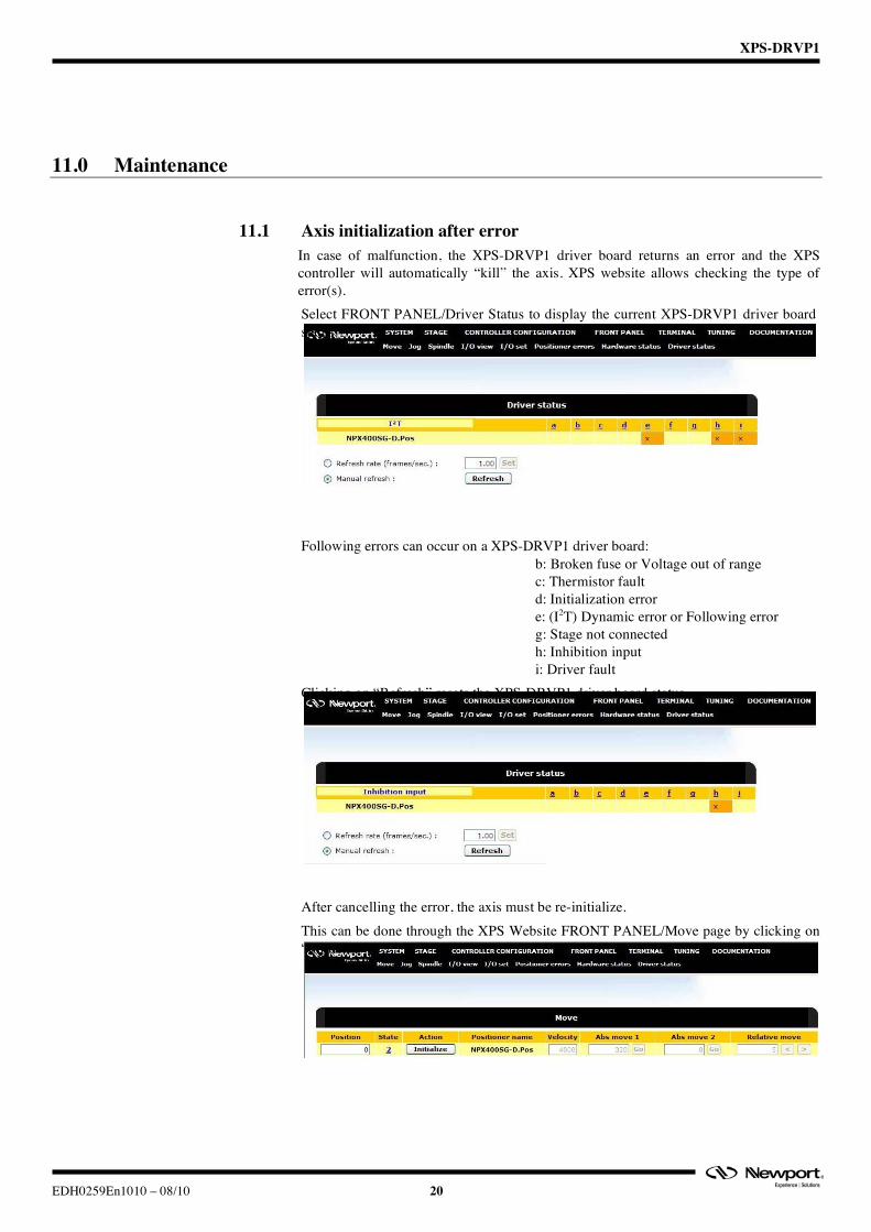
11.1 Axis initialization after error In case of malfunction, the XPS-DRVP1 driver board returns an error and the XPS controller will automatically “kill” the axis. XPS website allows checking the type of error(s). Select FRONT PANEL/Driver Status to display the current XPS-DRVP1 driver board status.
Following errors can occur on a XPS-DRVP1 driver board:
b: Broken fuse or Voltage out of range c: Thermistor fault d: Initialization error e: (I2T) Dynamic error or Following error g: Stage not connected h: Inhibition input i: Driver fault
Clicking on “Refresh” resets the XPS-DRVP1 driver board status. After cancelling the error, the axis must be re-initialize. This can be done through the XPS Website FRONT PANEL/Move page by clicking on “Initialize”.
XPS-DRVP1
21 EDH0259En1010 – 08/10
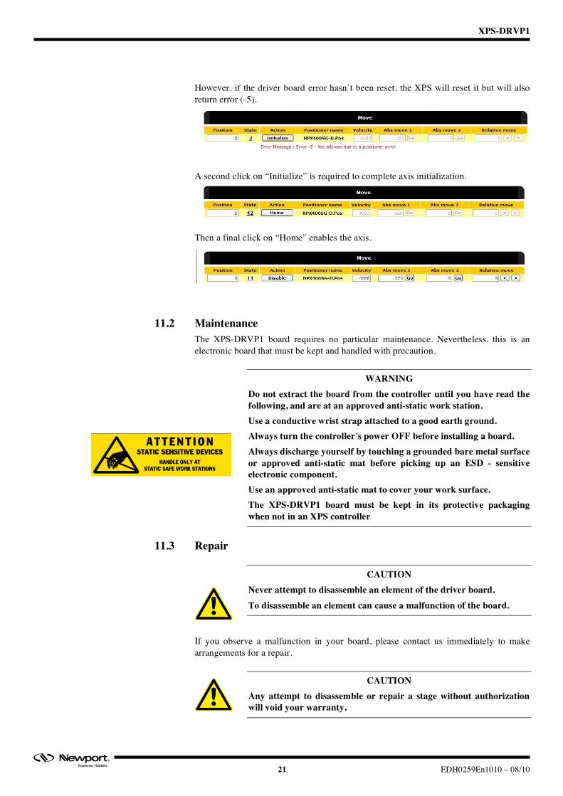
However, if the driver board error hasn’t been reset, the XPS will reset it but will also return error (-5). A second click on “Initialize” is required to complete axis initialization. Then a final click on “Home” enables the axis.
11.2 Maintenance The XPS-DRVP1 board requires no particular maintenance. Nevertheless, this is an electronic board that must be kept and handled with precaution.
WARNING Do not extract the board from the controller until you have read the following, and are at an approved anti-static work station. Use a conductive wrist strap attached to a good earth ground. Always turn the controller's power OFF before installing a board. Always discharge yourself by touching a grounded bare metal surface or approved anti-static mat before picking up an ESD - sensitive electronic component. Use an approved anti-static mat to cover your work surface. The XPS-DRVP1 board must be kept in its protective packaging when not in an XPS controller
11.3 Repair
CAUTION Never attempt to disassemble an element of the driver board. To disassemble an element can cause a malfunction of the board.
If you observe a malfunction in your board, please contact us immediately to make arrangements for a repair.
CAUTION Any attempt to disassemble or repair a stage without authorization will void your warranty.

XPS-DRVP1
EDH0259En1010 – 08/10 22

XPS-DRVP1
EDH0259En1010 – 08/10 23
Service Form Your Local Representative
Tel.: ___________________
Fax: ___________________
Name: __________________________________________________ Return authorization #: _____________________________________
Company: _______________________________________________ (Please obtain prior to return of item)
Address: ________________________________________________ Date: ___________________________________________________
Country: ________________________________________________ Phone Number: ___________________________________________
P.O. Number: ____________________________________________ Fax Number: _____________________________________________
Item(s) Being Returned: ____________________________________
Model#:_________________________________________________ Serial #:_________________________________________________
Description:_________________________________________________________________________________________________________
Reasons of return of goods (please list any specific problems): _________________________________________________________________
__________________________________________________________________________________________________________________
__________________________________________________________________________________________________________________
__________________________________________________________________________________________________________________
__________________________________________________________________________________________________________________
__________________________________________________________________________________________________________________
__________________________________________________________________________________________________________________
__________________________________________________________________________________________________________________
__________________________________________________________________________________________________________________
__________________________________________________________________________________________________________________
__________________________________________________________________________________________________________________
__________________________________________________________________________________________________________________
__________________________________________________________________________________________________________________
__________________________________________________________________________________________________________________
__________________________________________________________________________________________________________________
__________________________________________________________________________________________________________________
__________________________________________________________________________________________________________________
__________________________________________________________________________________________________________________
__________________________________________________________________________________________________________________
__________________________________________________________________________________________________________________
__________________________________________________________________________________________________________________
__________________________________________________________________________________________________________________
__________________________________________________________________________________________________________________
__________________________________________________________________________________________________________________
__________________________________________________________________________________________________________________
__________________________________________________________________________________________________________________
__________________________________________________________________________________________________________________
__________________________________________________________________________________________________________________
__________________________________________________________________________________________________________________

North America & Asia Newport Corporation 1791 Deere Ave. Irvine, CA 92606, USA Sales Tel.: (949) 253-1461 or (800) 222-6440 x31461 e-mail: [email protected] Technical Support Tel.: (949) 253-1406 or (800) 222-6440 x31406 e-mail: [email protected] Service, RMAs & Returns Tel.: (949) 253-1694 or (800) 222-6440 x31694 e-mail: [email protected]
Europe MICRO-CONTROLE Spectra-Physics S.A.S 1, rue Jules Guesde – Bât. B ZI Bois de l’Épine – BP189 91006 Evry Cedex France Sales Tel.: +33 (0)1.60.91.68.68 e-mail: [email protected] Technical Support e-mail: [email protected] Service & Returns Tel.: +33 (0)2.38.40.51.55
Visit Newport Online at: www.newport.com