Embed Size (px)
Citation preview
DriveIT Low Voltage AC Drives
Installation Supplement ACS550-U2 Drives (150…550 HP)
Phone: 800.894.0412 - Fax: 888.723.4773 - Web: www.clrwtr.com - Email: [email protected]

2 Installation Supplement for ACS550-U2 Drives
ACS550 Drive ManualsGENERAL MANUALS
ACS550-01/U1 User’s Manual (0.75…90 kW) / (1…150 HP) • Safety• Installation
• Start-Up• Diagnostics• Maintenance
• Technical DataACS550-02/U2 User’s Manual (110…355 kW) / (150…550 HP) • Safety• Installation• Start-Up
• Diagnostics• Maintenance• Technical Data
ACS550 Technical Reference Manual• Detailed Product Description
– Technical product description including Dimensional drawings
– Cabinet mounting information including power losses
– Software and control including complete parameter descriptions
– User interfaces and control connections
– Complete options descriptions– Spare parts– Etc.
• Practical Engineering Guides– PID & PFC engineering guides– Dimensioning and sizing guidelines
– Diagnostics and Maintenance information– Etc.
OPTION MANUALS (Fieldbus Adapters, I/O Extension Modules etc., manuals delivered with optional equipment)
Relay Output Extension Module (typical title)• Installation• Start-Up
• Diagnostics• Technical Data
Phone: 800.894.0412 - Fax: 888.723.4773 - Web: www.clrwtr.com - Email: [email protected]
Installation Supplement for ACS550-U2 Drives 3
Safety
Safety
Use of warnings and notes
There are two types of safety instructions throughout this manual:
• Notes draw attention to a particular condition or fact, or give information on a subject.
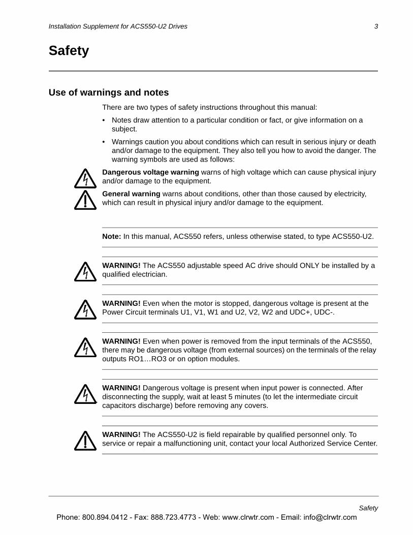
• Warnings caution you about conditions which can result in serious injury or death and/or damage to the equipment. They also tell you how to avoid the danger. The warning symbols are used as follows:
Dangerous voltage warning warns of high voltage which can cause physical injury and/or damage to the equipment.
General warning warns about conditions, other than those caused by electricity, which can result in physical injury and/or damage to the equipment.
Note: In this manual, ACS550 refers, unless otherwise stated, to type ACS550-U2.
WARNING! The ACS550 adjustable speed AC drive should ONLY be installed by a qualified electrician.
WARNING! Even when the motor is stopped, dangerous voltage is present at the Power Circuit terminals U1, V1, W1 and U2, V2, W2 and UDC+, UDC-.
WARNING! Even when power is removed from the input terminals of the ACS550, there may be dangerous voltage (from external sources) on the terminals of the relay outputs RO1…RO3 or on option modules.
WARNING! Dangerous voltage is present when input power is connected. After disconnecting the supply, wait at least 5 minutes (to let the intermediate circuit capacitors discharge) before removing any covers.
WARNING! The ACS550-U2 is field repairable by qualified personnel only. To service or repair a malfunctioning unit, contact your local Authorized Service Center.
Phone: 800.894.0412 - Fax: 888.723.4773 - Web: www.clrwtr.com - Email: [email protected]

4 Installation Supplement for ACS550-U2 Drives
Safety
WARNING! The ACS550 will start up automatically after an input voltage interruption if the external run command is on.
WARNING! When the control terminals of two or more drive units are connected in parallel, the auxiliary voltage for these control connections must be taken from a single source, which can either be one or the units, or an external supply.
WARNING! The heat sink may reach a high temperature. See Technical Data chapter in User’s Manual.
Phone: 800.894.0412 - Fax: 888.723.4773 - Web: www.clrwtr.com - Email: [email protected]
Installation Supplement for ACS550-U2 Drives 5
Table of contents
Table of contents
SafetyUse of warnings and notes . . . . . . . . . . . . . . . . . . . . . . . . . . . . . . . . . . . . . . . . . 3
Table of contents
InstallationIntroduction . . . . . . . . . . . . . . . . . . . . . . . . . . . . . . . . . . . . . . . . . . . . . . . . . . . . . 7Planning . . . . . . . . . . . . . . . . . . . . . . . . . . . . . . . . . . . . . . . . . . . . . . . . . . . . . . . 7Moving the unit . . . . . . . . . . . . . . . . . . . . . . . . . . . . . . . . . . . . . . . . . . . . . . . . . . 7Mounting . . . . . . . . . . . . . . . . . . . . . . . . . . . . . . . . . . . . . . . . . . . . . . . . . . . . . . . 8Connecting power and control cables . . . . . . . . . . . . . . . . . . . . . . . . . . . . . . . . 8
MaintenanceSafety . . . . . . . . . . . . . . . . . . . . . . . . . . . . . . . . . . . . . . . . . . . . . . . . . . . . . . . . 11Separating the drive and extension modules . . . . . . . . . . . . . . . . . . . . . . . . . . 11
Technical dataRatings . . . . . . . . . . . . . . . . . . . . . . . . . . . . . . . . . . . . . . . . . . . . . . . . . . . . . . . 13Fuses . . . . . . . . . . . . . . . . . . . . . . . . . . . . . . . . . . . . . . . . . . . . . . . . . . . . . . . . 15Cable entries . . . . . . . . . . . . . . . . . . . . . . . . . . . . . . . . . . . . . . . . . . . . . . . . . . 16Input power (mains) connection . . . . . . . . . . . . . . . . . . . . . . . . . . . . . . . . . . . . 16Power factor compensation capacitors . . . . . . . . . . . . . . . . . . . . . . . . . . . . . . 17Motor connection . . . . . . . . . . . . . . . . . . . . . . . . . . . . . . . . . . . . . . . . . . . . . . . 18Control connections . . . . . . . . . . . . . . . . . . . . . . . . . . . . . . . . . . . . . . . . . . . . . 19Efficiency . . . . . . . . . . . . . . . . . . . . . . . . . . . . . . . . . . . . . . . . . . . . . . . . . . . . . 19Cooling and required free space . . . . . . . . . . . . . . . . . . . . . . . . . . . . . . . . . . . 19Dimensions, weights and noise . . . . . . . . . . . . . . . . . . . . . . . . . . . . . . . . . . . . 19Degrees of protection . . . . . . . . . . . . . . . . . . . . . . . . . . . . . . . . . . . . . . . . . . . . 20Ambient conditions . . . . . . . . . . . . . . . . . . . . . . . . . . . . . . . . . . . . . . . . . . . . . . 20Dimension drawings . . . . . . . . . . . . . . . . . . . . . . . . . . . . . . . . . . . . . . . . . . . . . 21
Phone: 800.894.0412 - Fax: 888.723.4773 - Web: www.clrwtr.com - Email: [email protected]
Installation Supplement for ACS550-U2 Drives 7
Installation
Installation
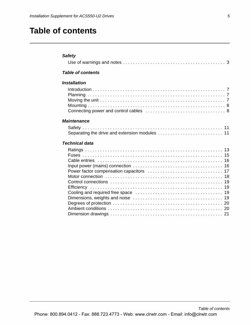
Introduction
ACS550-U2 drives include an extension module that is not covered in the ACS550-02/U2 User’s Manual. The extension module is attached to the drive module at the factory.
This supplement provides the additional extension module information required for ACS550-U2 drives:
• Additional installation steps and considerations.
• Steps for separating the drive from the extension module for drive service access.
• Dimensions for the extension module.
This supplement requires and routinely refers to the document: ACS550-02/U2 User’s Manual.
WARNING! Only qualified electricians are allowed to carry out the work described in this chapter. Follow requirements in Safety on the first pages of this manual. Ignoring the safety instructions can cause injury or death.
Planning
When planning for cable/conduit routing, refer to the ACS550-02/U2 User’s Manual, but note that, for the ACS550-U2, all connections are routed through the top of the extension module.
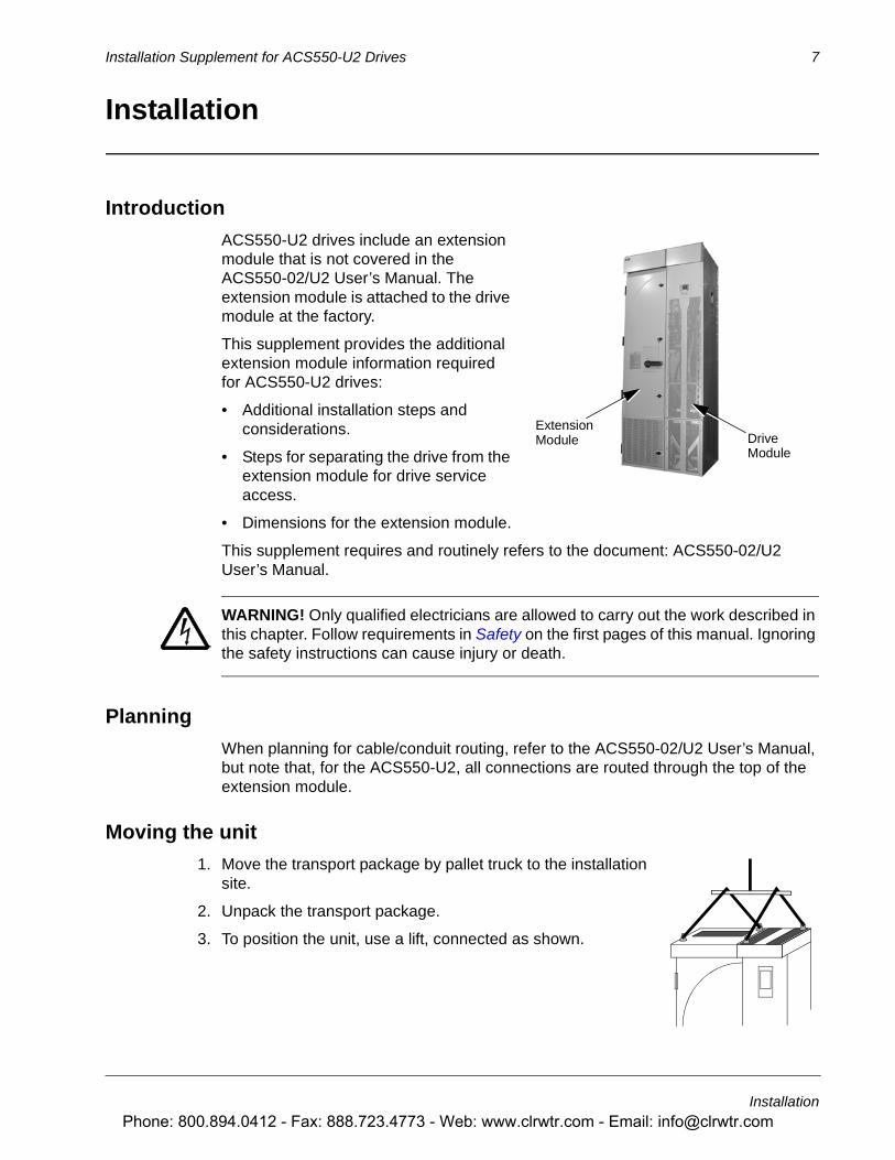
Moving the unit
1. Move the transport package by pallet truck to the installation site.
2. Unpack the transport package.
3. To position the unit, use a lift, connected as shown.
DriveExtensionModule
Module
Phone: 800.894.0412 - Fax: 888.723.4773 - Web: www.clrwtr.com - Email: [email protected]

8 Installation Supplement for ACS550-U2 Drives
Installation
Mounting
Fastening the Unit
See the Dimension drawings in the Technical data section of this document for the exact locations of the mounting points.
4. Use at least four screws – two at the front, two at the back – to attach the unit base plate to the floor.
5. Use at least two screws to attach the back of the enclosure to a wall.
There are two holes available at the top of each: the extension module and the drive module.
Connecting power and control cables
Additional considerations that apply with the enclosure extension:
• The power cable connection diagram that applies for the ACS550-U2 is:
• Temporarily remove the upper high voltage shield (clear plastic) to gain access to the power connections in the extension module.
• To avoid metal shavings inside the cabinet, temporarily remove the gland/conduit plate at the top of the extension module. Then drill holes and mount conduit or cable fittings as needed.
Extension Module ACS550-02
Control Panel
Switch-fuse Disconnect
3 ~Motor
Supply
ControlWiring
Drive Module
V2U2 W2V1U1 W1
3
3
3
L1 L2 L3 PE U1V1
W1
PE
PE
OMIO
Phone: 800.894.0412 - Fax: 888.723.4773 - Web: www.clrwtr.com - Email: [email protected]

Installation Supplement for ACS550-U2 Drives 9
Installation
• Route all power and control wiring through the top of the extension module.
• The following diagram shows the power and control connection points in the enclosure module supplied with the R8 drive module.
• Re-mount the high voltage shield.
WARNING! Always replace all high voltage shields before applying power.
• See the ACS550-02/U2 User’s Manual for detailed instructions on control connections, installation check list and drive start-up process.
Switch Fuse
Input (U1,V1,W1)
Output (U2,V2,W2)
PE Connection
OMIO Board(Control Wiring Terminals and Option Module Mounts)
R8 Frame SizeGland/Conduit Plate(Cable fittings shown are typical examples)
Phone: 800.894.0412 - Fax: 888.723.4773 - Web: www.clrwtr.com - Email: [email protected]
Installation Supplement for ACS550-U2 Drives 11
Maintenance
Maintenance
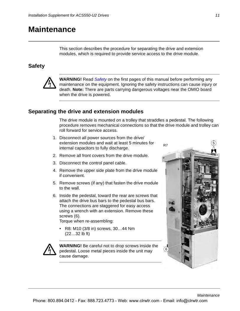
This section describes the procedure for separating the drive and extension modules, which is required to provide service access to the drive module.
Safety
WARNING! Read Safety on the first pages of this manual before performing any maintenance on the equipment. Ignoring the safety instructions can cause injury or death. Note: There are parts carrying dangerous voltages near the OMIO board when the drive is powered.
Separating the drive and extension modules
The drive module is mounted on a trolley that straddles a pedestal. The following procedure removes mechanical connections so that the drive module and trolley can roll forward for service access.
1. Disconnect all power sources from the drive/extension modules and wait at least 5 minutes for internal capacitors to fully discharge.
2. Remove all front covers from the drive module.
3. Disconnect the control panel cable.
4. Remove the upper side plate from the drive module if convenient.
5. Remove screws (if any) that fasten the drive module to the wall.
6. Inside the pedestal, toward the rear are screws that attach the drive bus bars to the pedestal bus bars. The connections are staggered for easy access using a wrench with an extension. Remove these screws (6). Torque when re-assembling:
• R8: M10 (3/8 in) screws, 30…44 Nm (22…32 lb ft)
WARNING! Be careful not to drop screws inside the pedestal. Loose metal pieces inside the unit may cause damage.
R75
6
Phone: 800.894.0412 - Fax: 888.723.4773 - Web: www.clrwtr.com - Email: [email protected]

12 Installation Supplement for ACS550-U2 Drives
Maintenance
7. The following cables between the drive and the extension module are split by a connector located at the front of the drive. Disconnect both cables at this location.
• The power supply cable to the OMIO board.
• The power supply cable to the extension module cooling fan.
8. At the OTIF board, disconnect the two fiber optic cables. Make note of the terminal colors for use when reconnecting.
9. Carefully remove the cables disconnected in the above steps: Pull the cables down inside the pedestal and bundle them so that they will not get damaged or caught in the trolley when the drive module is wheeled out.
10. Remove screws fastening the drive module trolley to the pedestal.
WARNING! These screws are an important step during re-assembly – the screws are required for grounding the drive.
11. R8: The front of the trolley includes support braces that fold out. Lift each brace slightly and fold it out.
12. Remove screws that fasten the drive module to the extension module.
CAUTION! The drive module is now separated and could tip over. Use care when moving the drive module.
13. Pull on the handle to wheel the drive module out.
Drive maintenance
See the ACS550-02/U2 User’s Manual for drive maintenance procedures.
Re-assembly
Re-attach the modules in reverse order to the above.
R7
7
8
9
R7
13
10
10 Pedestal
Trolley
12
Phone: 800.894.0412 - Fax: 888.723.4773 - Web: www.clrwtr.com - Email: [email protected]
Installation Supplement for ACS550-U2 Drives 13
Technical data
Technical data
Ratings
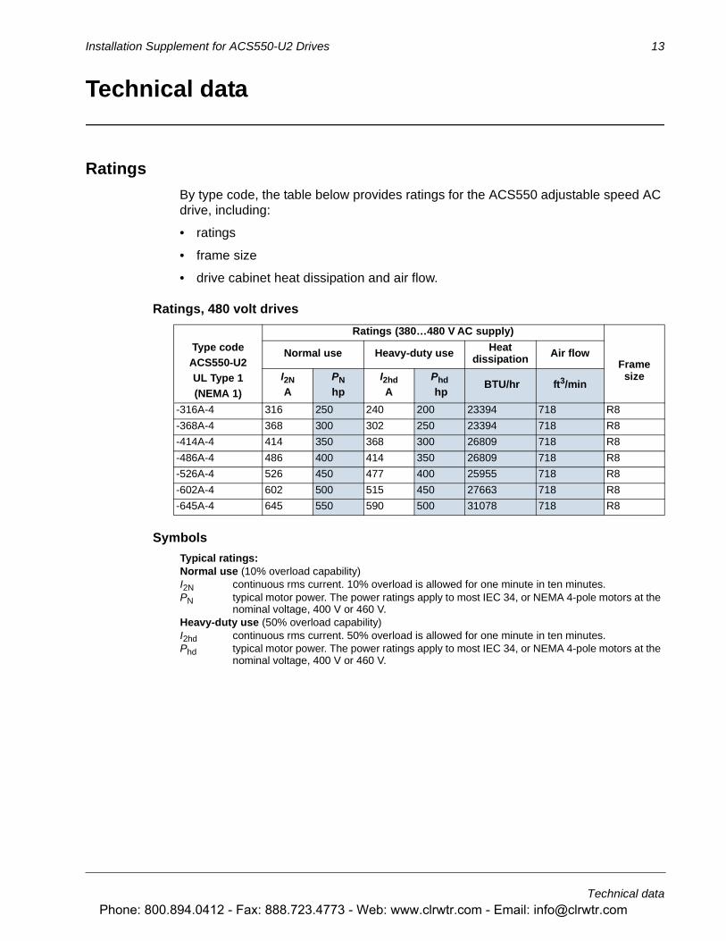
By type code, the table below provides ratings for the ACS550 adjustable speed AC drive, including:
• ratings
• frame size
• drive cabinet heat dissipation and air flow.
Ratings, 480 volt drives
Symbols
Ratings (380…480 V AC supply)
Type codeACS550-U2UL Type 1(NEMA 1)
Normal use Heavy-duty use Heat dissipation Air flow
FramesizeI2N
APNhp
I2hd A
Phd hp
BTU/hr ft3/min
-316A-4 316 250 240 200 23394 718 R8
-368A-4 368 300 302 250 23394 718 R8
-414A-4 414 350 368 300 26809 718 R8
-486A-4 486 400 414 350 26809 718 R8
-526A-4 526 450 477 400 25955 718 R8
-602A-4 602 500 515 450 27663 718 R8
-645A-4 645 550 590 500 31078 718 R8
Typical ratings:Normal use (10% overload capability)I2N continuous rms current. 10% overload is allowed for one minute in ten minutes. PN typical motor power. The power ratings apply to most IEC 34, or NEMA 4-pole motors at the
nominal voltage, 400 V or 460 V. Heavy-duty use (50% overload capability)I2hd continuous rms current. 50% overload is allowed for one minute in ten minutes.Phd typical motor power. The power ratings apply to most IEC 34, or NEMA 4-pole motors at the
nominal voltage, 400 V or 460 V.
Phone: 800.894.0412 - Fax: 888.723.4773 - Web: www.clrwtr.com - Email: [email protected]
14 Installation Supplement for ACS550-U2 Drives
Technical data
Sizing
The current ratings are the same regardless of the supply voltage within one voltage range. To achieve the rated motor power given in the table, the rated current of the drive must be higher than or equal to the rated motor current.
Note 1: The maximum allowed motor shaft power is limited to 1.5 · Phd. If the limit is exceeded, motor torque and current are automatically restricted. The function protects the input bridge of the drive against overload.
Note 2: The ratings apply in ambient temperature of 40 °C (104 °F).
Derating
The load capacity (current and power) decreases if the installation site altitude exceeds 1000 meters (3300 ft) or if the ambient temperature exceeds 40 °C (104 °F).
Temperature derating
In the temperature range +40 °C…50 °C (+104 °F…122 °F), the rated output current is decreased 1% for every 1 °C (1.8 °F) above +40 °C (+104 °F). Calculate the output current by multiplying the current given in the rating table by the derating factor.
Example If the ambient temperature is 50 °C (+122 °F), the derating factor is 100% - 1%/°C · 10 °C = 90% or 0.90. The output current is then 0.90 · I2N or 0.90 · I2hd.
Altitude derating
In altitudes from 1000…4000 m (3300…13,200 ft) above sea level, the derating is 1% for every 100 m (330 ft). If the installation site is higher than 2000 m (6600 ft) above sea level, please contact your local ABB distributor or office for further information.
Phone: 800.894.0412 - Fax: 888.723.4773 - Web: www.clrwtr.com - Email: [email protected]
Installation Supplement for ACS550-U2 Drives 15
Technical data
Fuses
Fuses
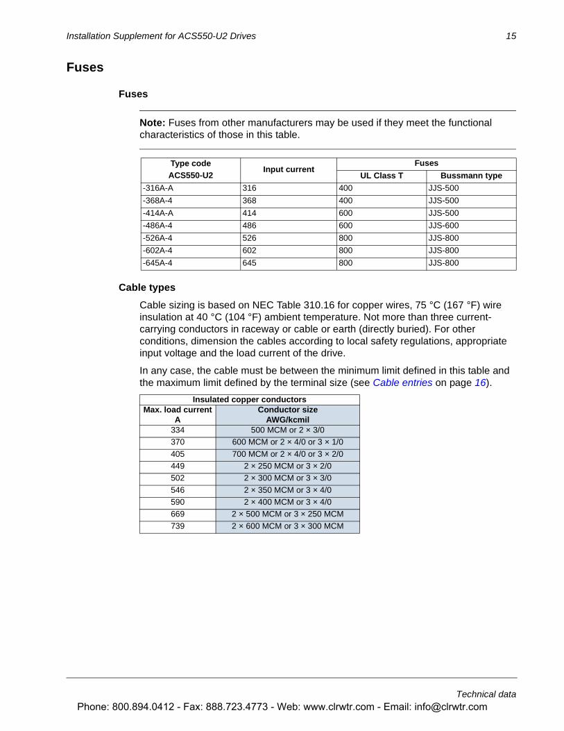
Note: Fuses from other manufacturers may be used if they meet the functional characteristics of those in this table.
Cable types
Cable sizing is based on NEC Table 310.16 for copper wires, 75 °C (167 °F) wire insulation at 40 °C (104 °F) ambient temperature. Not more than three current-carrying conductors in raceway or cable or earth (directly buried). For other conditions, dimension the cables according to local safety regulations, appropriate input voltage and the load current of the drive.
In any case, the cable must be between the minimum limit defined in this table and the maximum limit defined by the terminal size (see Cable entries on page 16).
Type codeACS550-U2
Input currentFuses
UL Class T Bussmann type
-316A-A 316 400 JJS-500
-368A-4 368 400 JJS-500
-414A-A 414 600 JJS-500
-486A-4 486 600 JJS-600
-526A-4 526 800 JJS-800
-602A-4 602 800 JJS-800
-645A-4 645 800 JJS-800
Insulated copper conductorsMax. load current
AConductor size
AWG/kcmil334 500 MCM or 2 × 3/0370 600 MCM or 2 × 4/0 or 3 × 1/0
405 700 MCM or 2 × 4/0 or 3 × 2/0449 2 × 250 MCM or 3 × 2/0502 2 × 300 MCM or 3 × 3/0
546 2 × 350 MCM or 3 × 4/0590 2 × 400 MCM or 3 × 4/0669 2 × 500 MCM or 3 × 250 MCM
739 2 × 600 MCM or 3 × 300 MCM
Phone: 800.894.0412 - Fax: 888.723.4773 - Web: www.clrwtr.com - Email: [email protected]
16 Installation Supplement for ACS550-U2 Drives
Technical data
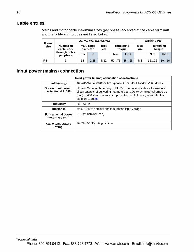
Cable entries
Mains and motor cable maximum sizes (per phase) accepted at the cable terminals, and the tightening torques are listed below.
Input power (mains) connection
Frame size
U1, V1, W1, U2, V2, W2 Earthing PE
Number of cable lead-
through holes per phase
Max. cable diameter
Bolt size
Tightening torque
Bolt size
Tightening torque
mm in N·m lbf·ft N·m lbf·ft
R8 3 58 2.28 M12 50…75 35…55 M8 15…22 10…16
Input power (mains) connection specifications
Voltage (U1) 400/415/440/460/480 V AC 3-phase +10% -15% for 400 V AC drives
Short-circuit current protection (UL 508)
US and Canada: According to UL 508, the drive is suitable for use in a circuit capable of delivering not more than 100 kA symmetrical amperes (rms) at 480 V maximum when protected by UL fuses given in the fuse table on page 15.
Frequency 48…63 Hz
Imbalance Max. ± 3% of nominal phase to phase input voltage
Fundamental power factor (cos phi1)
0.98 (at nominal load)
Cable temperature rating
70 °C (158 °F) rating minimum
Phone: 800.894.0412 - Fax: 888.723.4773 - Web: www.clrwtr.com - Email: [email protected]
Installation Supplement for ACS550-U2 Drives 17
Technical data
Power factor compensation capacitors
Power factor compensation is not needed with AC drives. However, if a drive is to be connected in a system with compensation capacitors installed, note the following restrictions.
WARNING! Do not connect power factor compensation capacitors or surge absorbers to the motor cables (between the drive and the motor). They are not meant to be used with AC drives and can cause permanent damage to the drive or themselves.
If there are power factor compensation capacitors in parallel with the three phase input of the drive:
1. Do not connect a high-power capacitor to the power line while the drive is connected. The connection will cause voltage transients that may trip or even damage the drive.
2. If capacitor load is increased/decreased step by step when the AC drive is connected to the power line: Ensure that the connection steps are low enough not to cause voltage transients that would trip the drive.
3. Check that the power factor compensation unit is suitable for use in systems with AC drives, i.e. harmonic generating loads. In such systems, the compensation unit should typically be equipped with a blocking reactor or harmonic filter.
Phone: 800.894.0412 - Fax: 888.723.4773 - Web: www.clrwtr.com - Email: [email protected]
18 Installation Supplement for ACS550-U2 Drives
Technical data
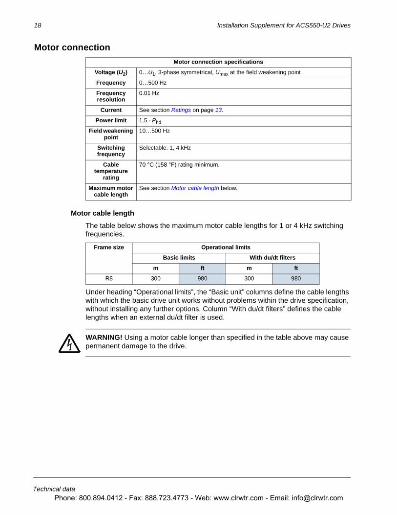
Motor connection
Motor cable length
The table below shows the maximum motor cable lengths for 1 or 4 kHz switching frequencies.
Under heading “Operational limits”, the “Basic unit” columns define the cable lengths with which the basic drive unit works without problems within the drive specification, without installing any further options. Column “With du/dt filters” defines the cable lengths when an external du/dt filter is used.
WARNING! Using a motor cable longer than specified in the table above may cause permanent damage to the drive.
Motor connection specifications
Voltage (U2) 0…U1, 3-phase symmetrical, Umax at the field weakening point
Frequency 0…500 Hz
Frequency resolution
0.01 Hz
Current See section Ratings on page 13.
Power limit 1.5 · Phd
Field weakening point
10…500 Hz
Switching frequency
Selectable: 1, 4 kHz
Cable temperature
rating
70 °C (158 °F) rating minimum.
Maximum motor cable length
See section Motor cable length below.
Frame size Operational limits
Basic limits With du/dt filters
m ft m ft
R8 300 980 300 980
Phone: 800.894.0412 - Fax: 888.723.4773 - Web: www.clrwtr.com - Email: [email protected]
Installation Supplement for ACS550-U2 Drives 19
Technical data
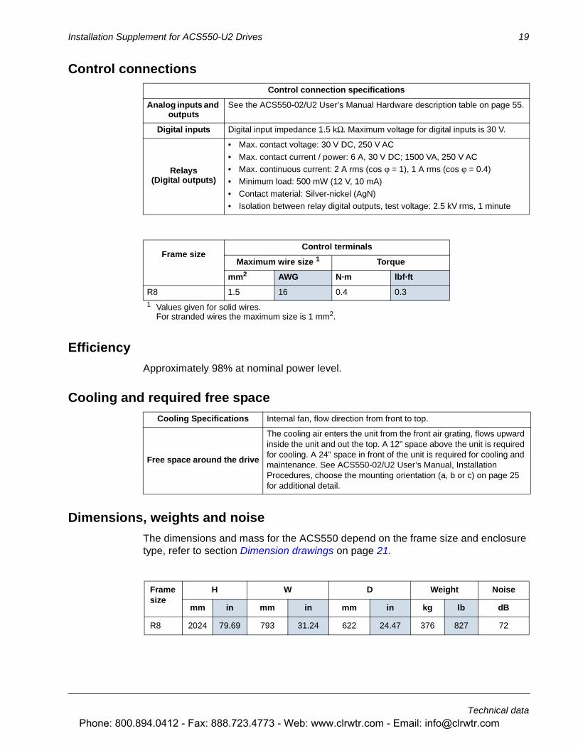
Control connections
Efficiency
Approximately 98% at nominal power level.
Cooling and required free space
Dimensions, weights and noise
The dimensions and mass for the ACS550 depend on the frame size and enclosure type, refer to section Dimension drawings on page 21.
Control connection specifications
Analog inputs and outputs
See the ACS550-02/U2 User’s Manual Hardware description table on page 55.
Digital inputs Digital input impedance 1.5 kΩ. Maximum voltage for digital inputs is 30 V.
Relays(Digital outputs)
• Max. contact voltage: 30 V DC, 250 V AC
• Max. contact current / power: 6 A, 30 V DC; 1500 VA, 250 V AC• Max. continuous current: 2 A rms (cos ϕ = 1), 1 A rms (cos ϕ = 0.4)• Minimum load: 500 mW (12 V, 10 mA)
• Contact material: Silver-nickel (AgN)• Isolation between relay digital outputs, test voltage: 2.5 kV rms, 1 minute
Frame sizeControl terminals
Maximum wire size 1 Torque
mm2 AWG N·m lbf·ft
R8 1.5 16 0.4 0.31 Values given for solid wires.
For stranded wires the maximum size is 1 mm2.
Cooling Specifications Internal fan, flow direction from front to top.
Free space around the drive
The cooling air enters the unit from the front air grating, flows upward inside the unit and out the top. A 12" space above the unit is required for cooling. A 24" space in front of the unit is required for cooling and maintenance. See ACS550-02/U2 User’s Manual, Installation Procedures, choose the mounting orientation (a, b or c) on page 25 for additional detail.
Frame size
H W D Weight Noise
mm in mm in mm in kg lb dB
R8 2024 79.69 793 31.24 622 24.47 376 827 72
Phone: 800.894.0412 - Fax: 888.723.4773 - Web: www.clrwtr.com - Email: [email protected]
20 Installation Supplement for ACS550-U2 Drives
Technical data
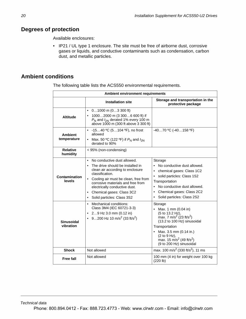
Degrees of protection
Available enclosures:
• IP21 / UL type 1 enclosure. The site must be free of airborne dust, corrosive gases or liquids, and conductive contaminants such as condensation, carbon dust, and metallic particles..
Ambient conditions
The following table lists the ACS550 environmental requirements.
Ambient environment requirements
Installation site Storage and transportation in the protective package
Altitude
• 0…1000 m (0…3 300 ft)• 1000…2000 m (3 300…6 600 ft) if
PN and I2N derated 1% every 100 m above 1000 m (300 ft above 3 300 ft)
Ambient temperature
• -15…40 ºC (5…104 ºF), no frost allowed
• Max. 50 ºC (122 ºF) if PN and I2N derated to 90%
-40…70 ºC (-40…158 ºF)
Relative humidity
< 95% (non-condensing)
Contamination levels
• No conductive dust allowed.• The drive should be installed in
clean air according to enclosure classification.
• Cooling air must be clean, free from corrosive materials and free from electrically conductive dust.
• Chemical gases: Class 3C2
• Solid particles: Class 3S2
Storage• No conductive dust allowed.
• chemical gases: Class 1C2• solid particles: Class 1S2Transportation
• No conductive dust allowed.• Chemical gases: Class 2C2• Solid particles: Class 2S2
Sinusoidalvibration
• Mechanical conditions: Class 3M4 (IEC 60721-3-3)
• 2…9 Hz 3.0 mm (0.12 in)• 9…200 Hz 10 m/s2 (33 ft/s2)
Storage• Max. 1 mm (0.04 in)
(5 to 13.2 Hz), max. 7 m/s2 (23 ft/s2) (13.2 to 100 Hz) sinusoidal
Transportation• Max. 3.5 mm (0.14 in.)
(2 to 9 Hz), max. 15 m/s2 (49 ft/s2) (9 to 200 Hz) sinusoidal
Shock Not allowed max. 100 m/s2 (330 ft/s2), 11 ms
Free fall Not allowed 100 mm (4 in) for weight over 100 kg (220 lb)
Phone: 800.894.0412 - Fax: 888.723.4773 - Web: www.clrwtr.com - Email: [email protected]
Installation Supplement for ACS550-U2 Drives 21
Technical data
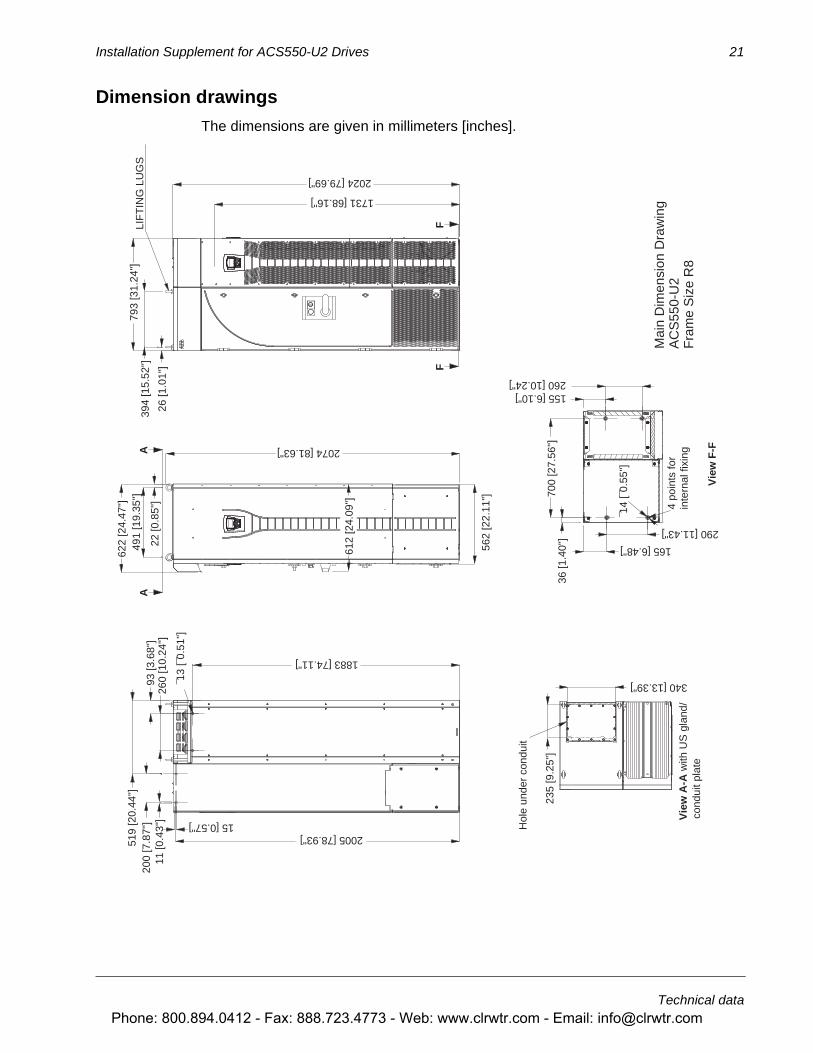
Dimension drawings
The dimensions are given in millimeters [inches].
Vie
w F
-F
4 po
ints
for
inte
rnal
fixi
ngV
iew
A-A
with
US
gla
nd/
cond
uit p
late
LIF
TIN
G L
UG
S
Hol
e un
der
cond
uit
2074 [81.63"]
22 [0
.85"
]
491
[19.
35"]
622
[24.
47"]
562
[22.
11"]
260
[10.
24"]
1883 [74.11"]
93 [3
.68"
]
519
[20.
44"]
200
[7.8
7"]
11 [0
.43"
] 15 [0.57"]
2024 [79.69"]
793
[31.
24"]
26 [1
.01"
]
394
[15.
52"]
1731 [68.16"]
36 [1
.40"
]70
0 [2
7.56
"]
165 [6.48"]
155 [6.10"]260 [10.24"]
290 [11.43"]
2005 [78.93"]
235
[9.2
5"]
340 [13.39"]
612
[24.
09"]
¯13
[¯0.
51"]
AA
FF
¯14
[¯0.
55"]
Mai
n D
imen
sion
Dra
win
gA
CS
550-
U2
Fra
me
Siz
e R
8
Phone: 800.894.0412 - Fax: 888.723.4773 - Web: www.clrwtr.com - Email: [email protected]

22 Installation Supplement for ACS550-U2 Drives
Technical data
Detail
Dimensions are listed in millimeters [inches]
Phone: 800.894.0412 - Fax: 888.723.4773 - Web: www.clrwtr.com - Email: [email protected]