Embed Size (px)
Citation preview
DRIVE SHAFT& FRONT AXLEReturn To Main Table of ContentsGENERAL . . . . . . . . . . . . . . . . . . . . . . . . . . . . . . . . . . . . . . . . . . . . . . 2
DRIVE SHAFT . . . . . . . . . . . . . . . . . . . . . . . . . . . . . . . . . . . . . . . . . . 7
HUB AND KNUCKLE . . . . . . . . . . . . . . . . . . . . . . . . . . . . . . . . . . 2 3
GENERAL
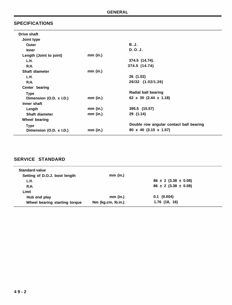
SPEClFlCATlONS
Drive shaftJoint type
OuterInner
Length (Joint to joint)L.H.
R.H.Shaft diameter
L.H.R.H.
Center bearing
TypeDimension (O.D. x I.D.)
Inner shaftLengthShaft diameter
Wheel bearing
TypeDimension (O.D. x I.D.)
mm (in.)
mm (in.)
mm (in.)
mm (in.)mm (in.)
mm (in.)
B . J .D . O . J .
374.5 (14.74).374.5 (14.74)
26 (1.02)26/32 (1.02/1.26)
Radial ball bearing
62 x 30 (2.44 x 1.18)
395.5 (15.57)29 (1.14)
Double row angular contact ball bearing
80 x 40 (3.15 x 1.57)
SERVICE STANDARD
Standard value
Setting of D.O.J. boot lengthL.H.
R.H.Limit
Hub end playWheel bearing starting torque
mm (in.)
mm (in.)
Nm (kg.cm, Ib.in.)
86 ± 2 (3.38 ± 0.08)86 ± 2 (3.38 ± 0.08)
0.1 (0.004)1.76 (18, 16)
4 9 - 2
GENERAL
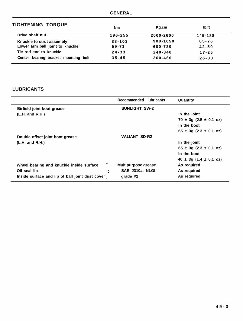
TIGHTENING TORQUENm Kg.cm Ib.ft
Drive shaft nut 1 9 6 - 2 5 5 2000-2600 145-188
Knuckle to strut assembly 8 8 - 1 0 3 9 0 0 - 1 0 5 0 6 5 - 7 6Lower arm ball joint to knuckle 5 9 - 7 1 6 0 0 - 7 2 0 4 2 - 5 0Tie rod end to knuckle 2 4 - 3 3 2 4 0 - 3 4 0 1 7 - 2 5Center bearing bracket mounting bolt 3 5 - 4 5 3 6 0 - 4 6 0 2 6 - 3 3
LUBRICANTS
Recommended lubricants Quantity
SUNLIGHT SW-2
VALIANT SD-R2
Birfield joint boot grease(L.H. and R.H.)
Double offset joint boot grease(L.H. and R.H.)
In the joint70 ± 3g (2.5 ± 0.1 oz)
In the boot65 ± 3g (2.3 ± 0.1 oz)
In the joint65 ± 3g (2.3 ± 0.1 oz)
In the boot40 ± 3g (1.4 ± 0.1 oz)
Wheel bearing and knuckle inside surfaceOil seal lipInside surface and lip of ball joint dust cover
Multipurpose grease As requiredSAE J310a, NLGI As required
grade #2 As required
4 9 - 3
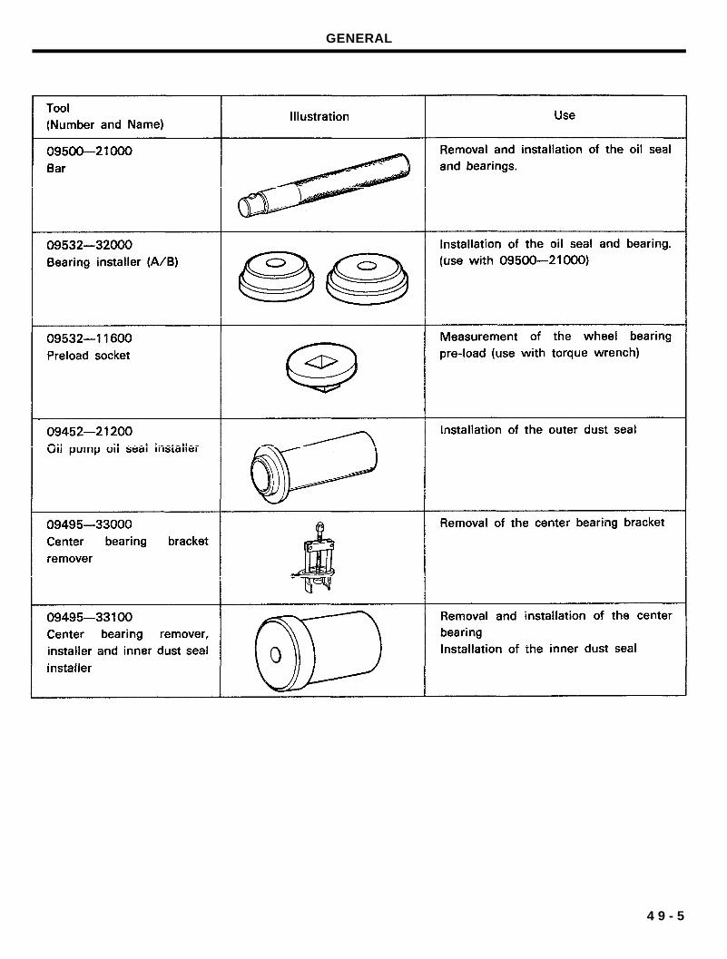
GENERAL
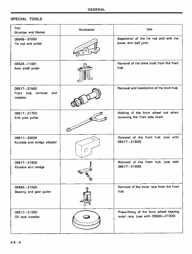
SPECIAL TOOLS
4 9 - 4
GENERAL
4 9 - 5
GENERAL
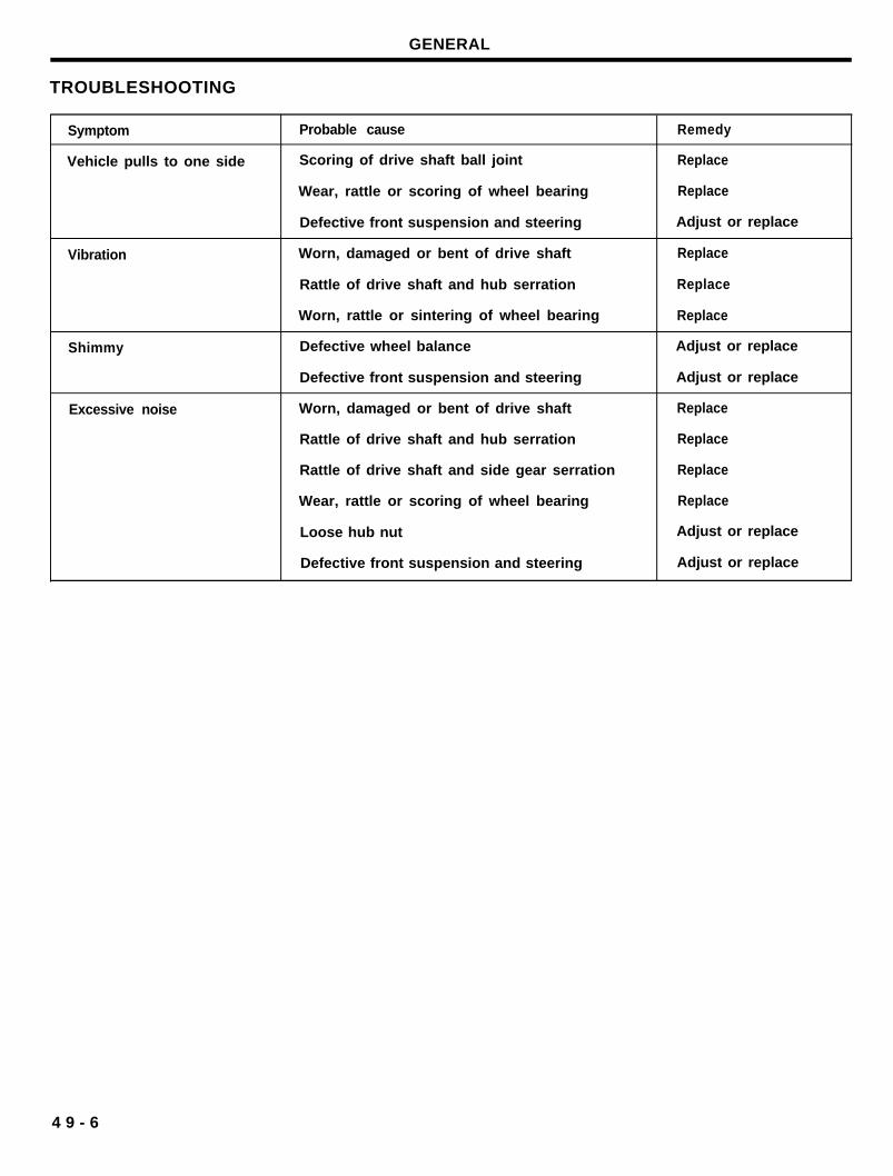
TROUBLESHOOTING
Symptom
Vehicle pulls to one side
Vibration
Shimmy
Excessive noise
Probable cause Remedy
Scoring of drive shaft ball joint Replace
Wear, rattle or scoring of wheel bearing Replace
Defective front suspension and steering Adjust or replace
Worn, damaged or bent of drive shaft Replace
Rattle of drive shaft and hub serration Replace
Worn, rattle or sintering of wheel bearing Replace
Defective wheel balance Adjust or replace
Defective front suspension and steering Adjust or replace
Worn, damaged or bent of drive shaft Replace
Rattle of drive shaft and hub serration Replace
Rattle of drive shaft and side gear serration Replace
Wear, rattle or scoring of wheel bearing Replace
Loose hub nut Adjust or replace
Defective front suspension and steering Adjust or replace
4 9 - 6
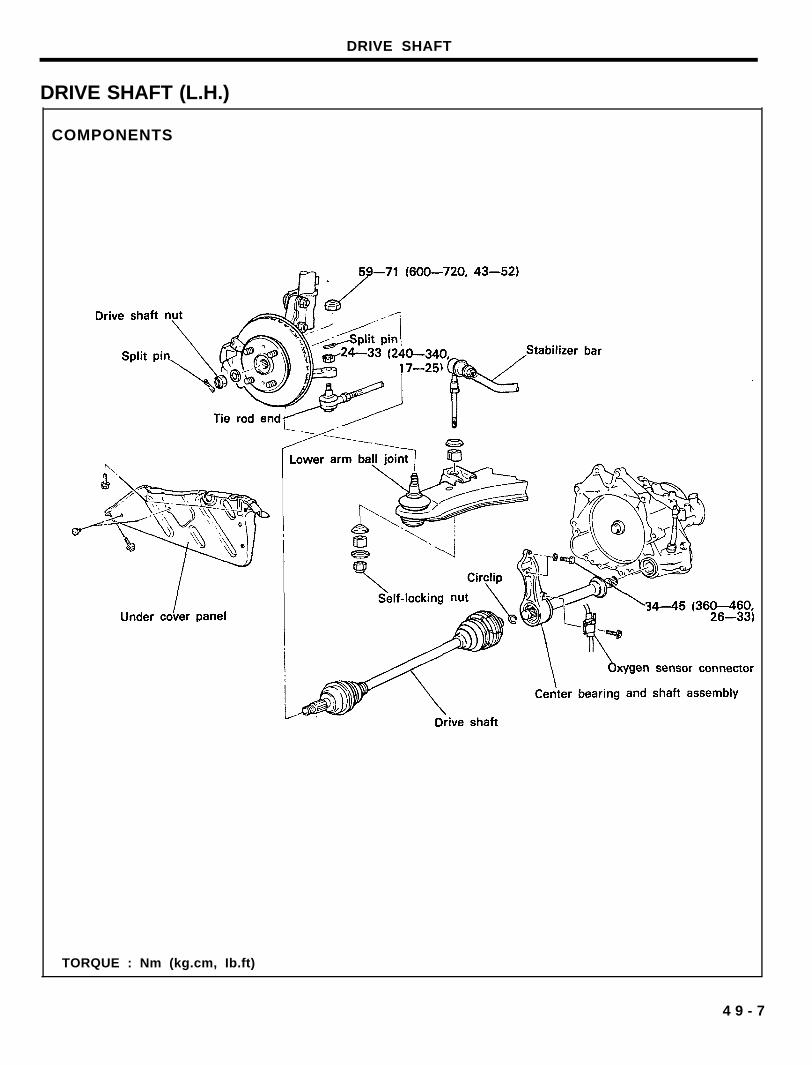
DRIVE SHAFT
DRIVE SHAFT (L.H.)
COMPONENTS
TORQUE : Nm (kg.cm, Ib.ft)
4 9 - 7
DRIVE SHAFT
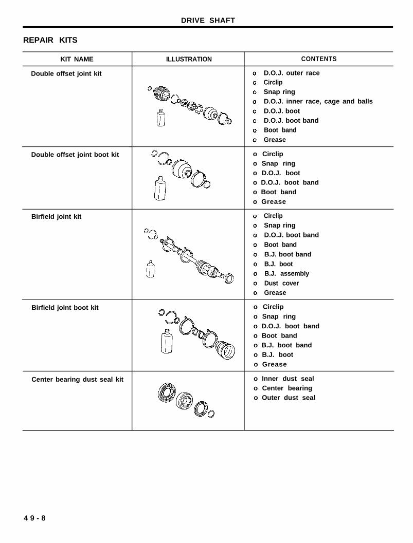
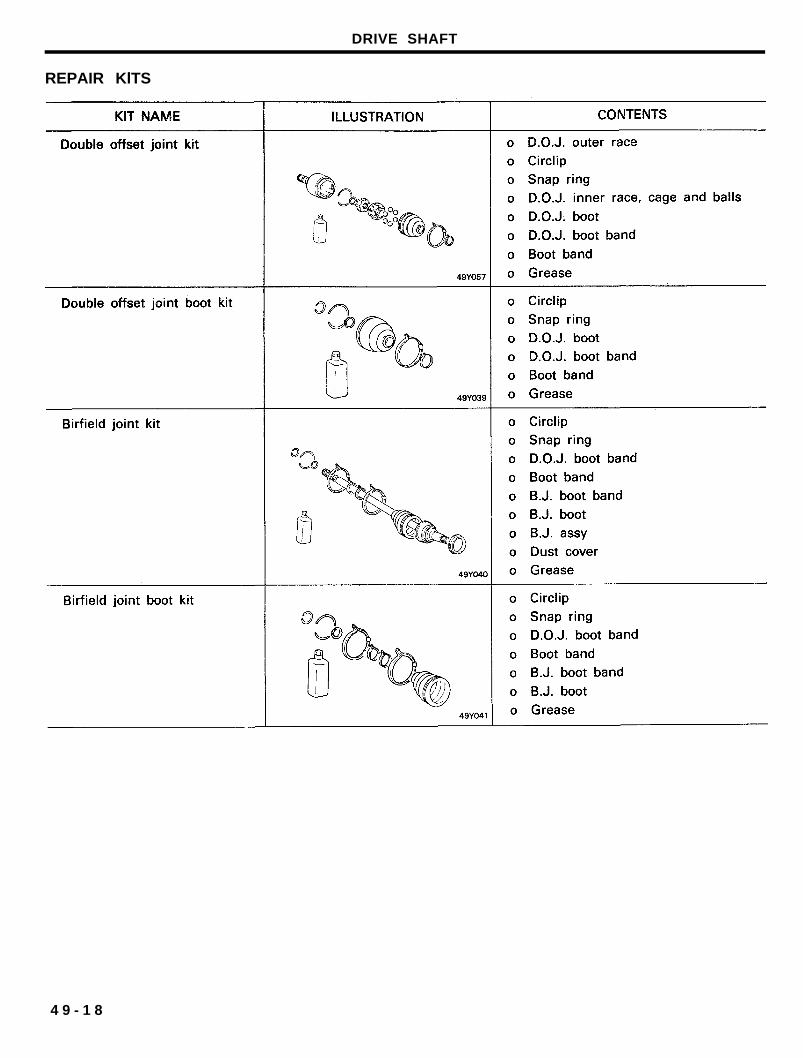
REPAIR KITS
KIT NAME
Double offset joint kit
Double offset joint boot kit
Birfield joint kit
Birfield joint boot kit
Center bearing dust seal kit
ILLUSTRATION CONTENTS
D.O.J. outer raceCirclipSnap ringD.O.J. inner race, cage and balls
D.O.J. bootD.O.J. boot bandBoot band
Grease
o Circlipo Snap ringo D.O.J. booto D.O.J. boot bando Boot band
o Grease
CirclipSnap ring
D.O.J. boot band
Boot band
B.J. boot band
B.J. bootB.J. assembly
Dust coverGrease
o Circlip
o Snap ring
o D.O.J. boot bando Boot bando B.J. boot bando B.J. boot
o Grease
o Inner dust sealo Center bearingo Outer dust seal
4 9 - 8
DRIVE SHAFT
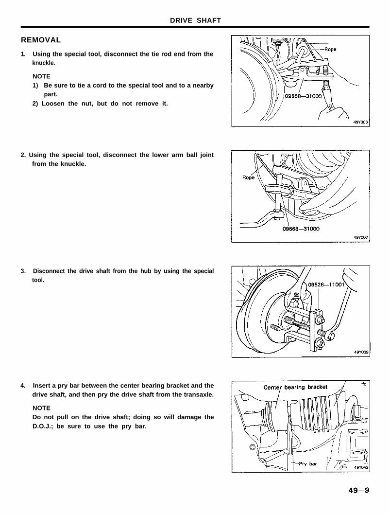
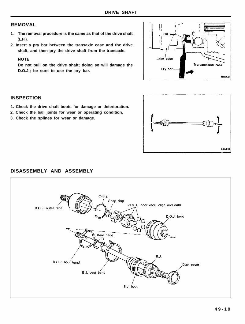
REMOVAL
1. Using the special tool, disconnect the tie rod end from theknuckle.
NOTE1) Be sure to tie a cord to the special tool and to a nearby
part.
2) Loosen the nut, but do not remove it.
2. Using the special tool, disconnect the lower arm ball jointfrom the knuckle.
3. Disconnect the drive shaft from the hub by using the specialtool.
4. Insert a pry bar between the center bearing bracket and thedrive shaft, and then pry the drive shaft from the transaxle.
NOTEDo not pull on the drive shaft; doing so will damage the
D.O.J.; be sure to use the pry bar.
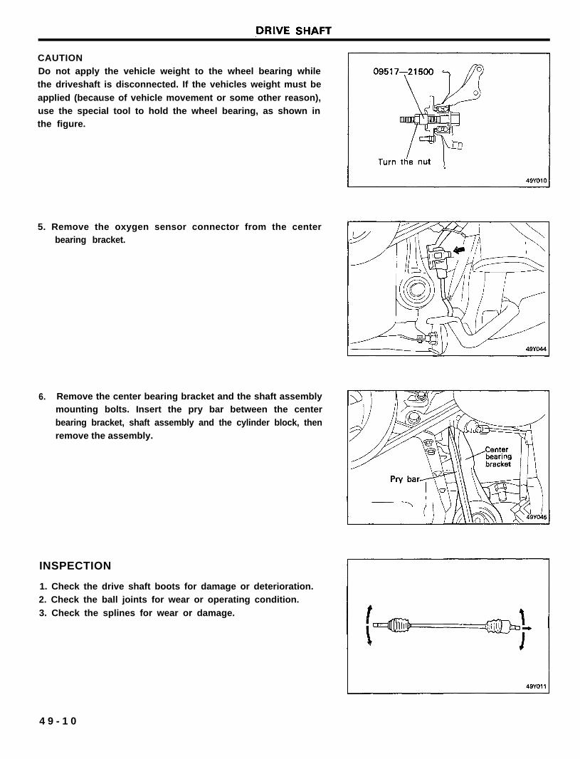
CAUTIONDo not apply the vehicle weight to the wheel bearing whilethe driveshaft is disconnected. If the vehicles weight must be
applied (because of vehicle movement or some other reason),use the special tool to hold the wheel bearing, as shown inthe figure.
5. Remove the oxygen sensor connector from the centerbearing bracket.
6. Remove the center bearing bracket and the shaft assemblymounting bolts. Insert the pry bar between the centerbearing bracket, shaft assembly and the cylinder block, thenremove the assembly.
INSPECTION
1. Check the drive shaft boots for damage or deterioration.2. Check the ball joints for wear or operating condition.
3. Check the splines for wear or damage.
4 9 - 1 0
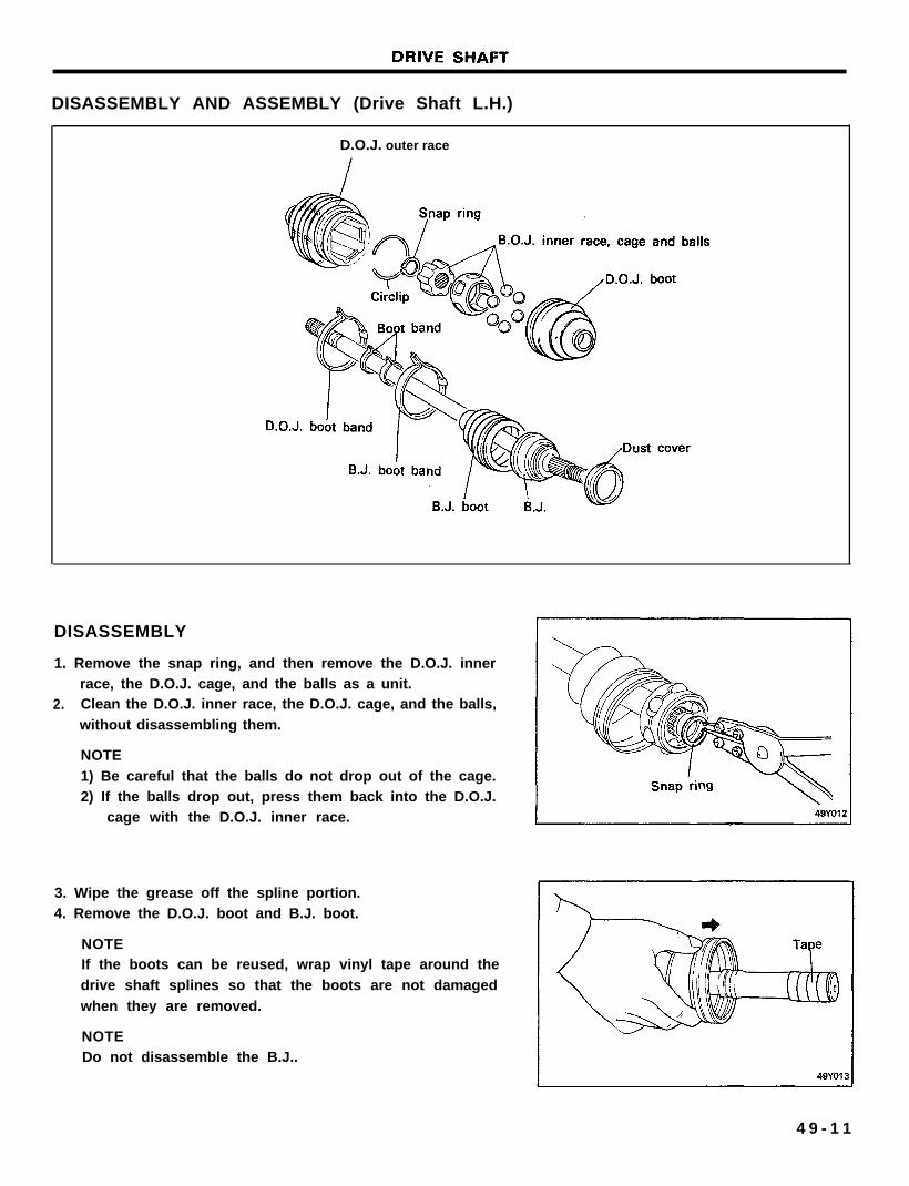
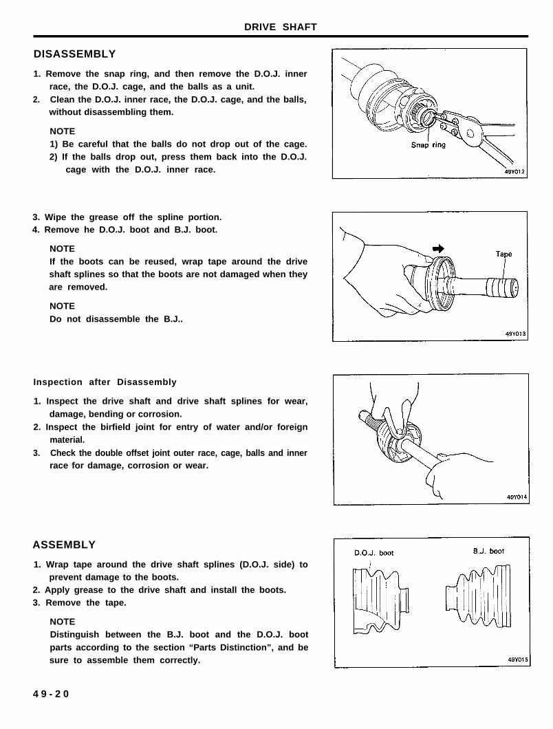
DISASSEMBLY AND ASSEMBLY (Drive Shaft L.H.)
D.O.J. outer race
DISASSEMBLY
1. Remove the snap ring, and then remove the D.O.J. innerrace, the D.O.J. cage, and the balls as a unit.
2. Clean the D.O.J. inner race, the D.O.J. cage, and the balls,
without disassembling them.
NOTE
1) Be careful that the balls do not drop out of the cage.2) If the balls drop out, press them back into the D.O.J.
cage with the D.O.J. inner race.
3. Wipe the grease off the spline portion.4. Remove the D.O.J. boot and B.J. boot.
NOTEIf the boots can be reused, wrap vinyl tape around the
drive shaft splines so that the boots are not damaged
when they are removed.
NOTEDo not disassemble the B.J..
4 9 - 1 1
DRIVE SHAFT
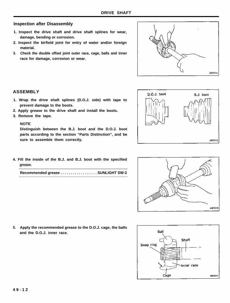
Inspection after Disassembly
1. Inspect the drive shaft and drive shaft splines for wear,damage, bending or corrosion.
2. Inspect the birfield joint for entry of water and/or foreignmaterial.
3. Check the double offset joint outer race, cage, balls and inner
race for damage, corrosion or wear.
ASSEMBLY
1. Wrap the drive shaft splines (D.O.J. side) with tape to
prevent damage to the boots.2. Apply grease to the drive shaft and install the boots.3. Remove the tape.
NOTEDistinguish between the B.J. boot and the D.O.J. boot
parts according to the section “Parts Distinction”, and besure to assemble them correctly.
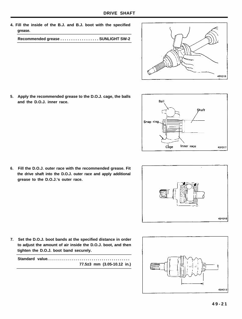
4. Fill the inside of the B.J. and B.J. boot with the specifiedgrease.
Recommended grease . . . . . . . . . . . . . . . . . . SUNLIGHT SW-2
5. Apply the recommended grease to the D.O.J. cage, the ballsand the D.O.J. inner race.
4 9 - 1 2
DRIVE SHAFT
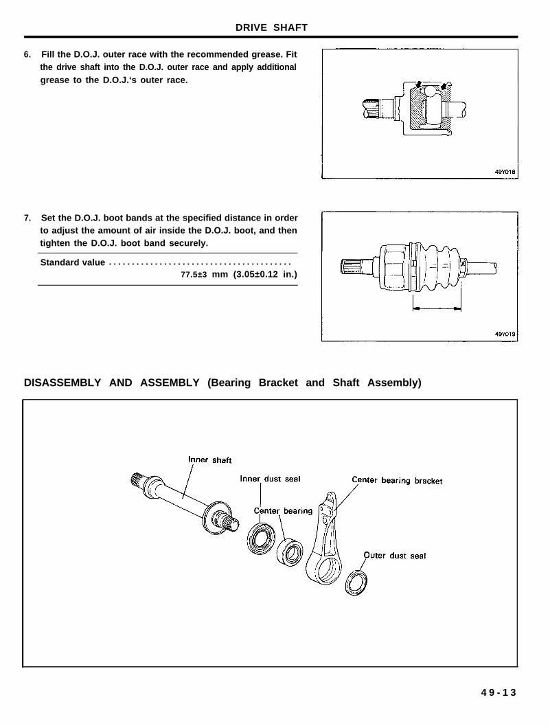
6. Fill the D.O.J. outer race with the recommended grease. Fitthe drive shaft into the D.O.J. outer race and apply additional
grease to the D.O.J.‘s outer race.
7. Set the D.O.J. boot bands at the specified distance in orderto adjust the amount of air inside the D.O.J. boot, and thentighten the D.O.J. boot band securely.
Standard value . . . . . . . . . . . . . . . . . . . . . . . . . . . . . . . . . . . . . . . .77.5±3 mm (3.05±0.12 in.)
DISASSEMBLY AND ASSEMBLY (Bearing Bracket and Shaft Assembly)
4 9 - 1 3
DRIVE SHAFT
DISASSEMBLY
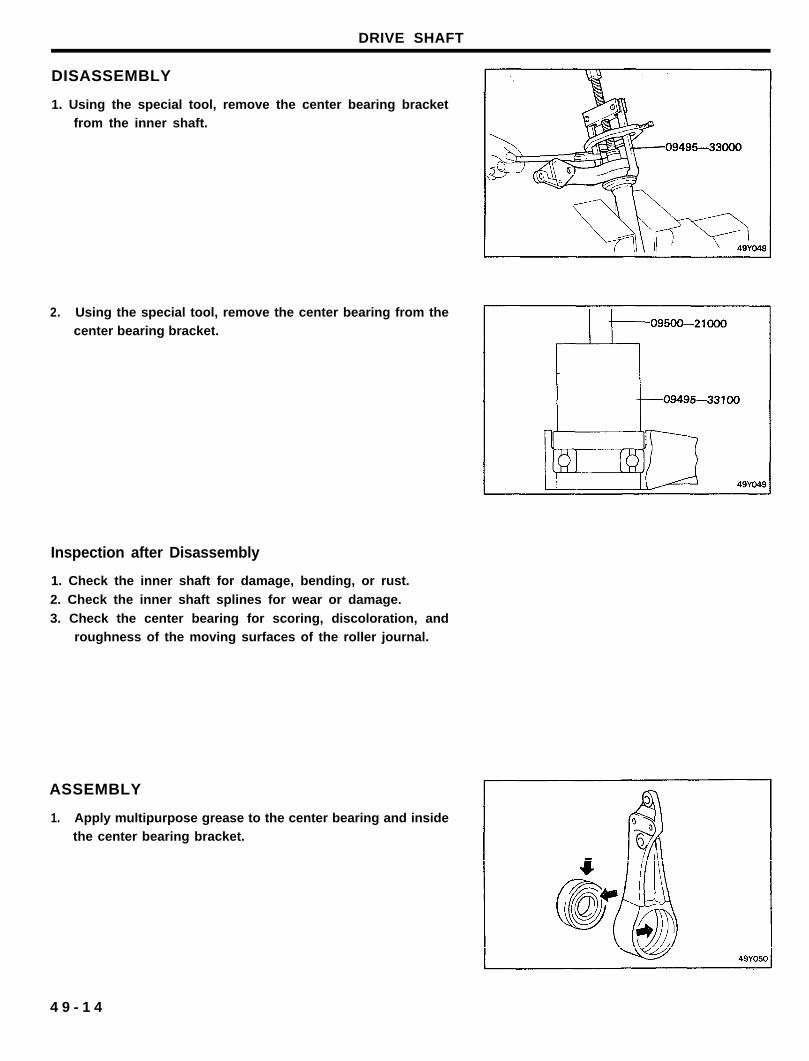
1. Using the special tool, remove the center bearing bracketfrom the inner shaft.
2. Using the special tool, remove the center bearing from thecenter bearing bracket.
Inspection after Disassembly
1. Check the inner shaft for damage, bending, or rust.
2. Check the inner shaft splines for wear or damage.
3. Check the center bearing for scoring, discoloration, androughness of the moving surfaces of the roller journal.
ASSEMBLY
1. Apply multipurpose grease to the center bearing and insidethe center bearing bracket.
4 9 - 1 4
DRIVE SHAFT
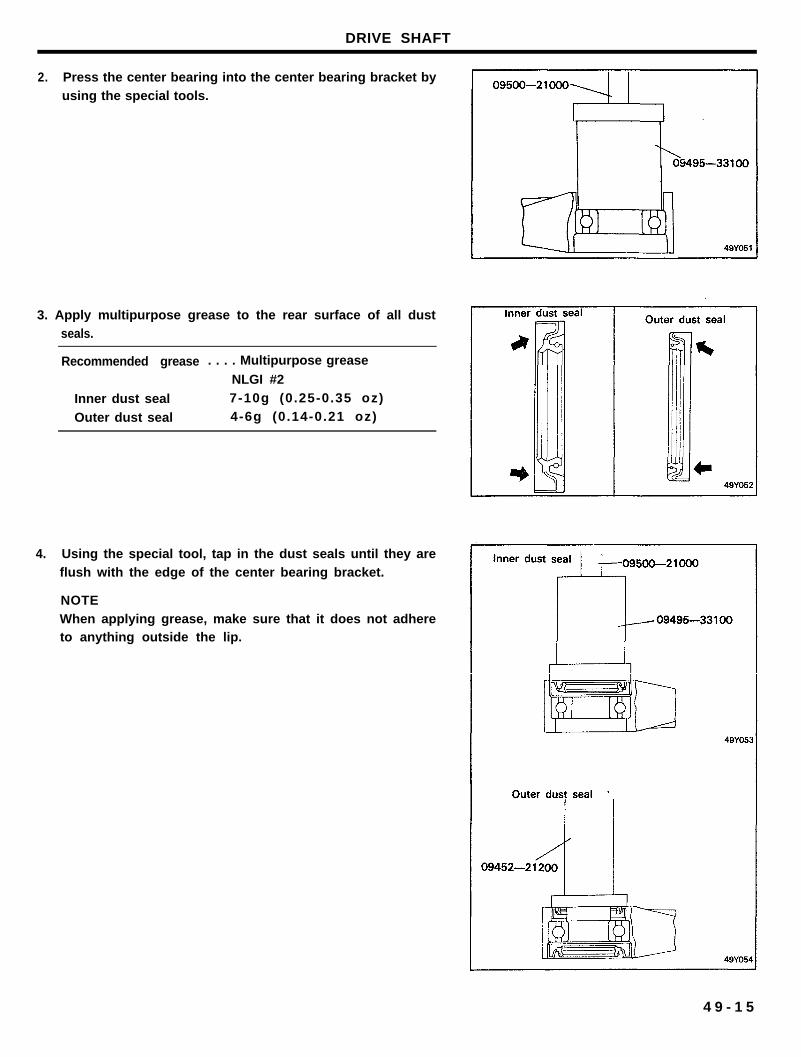
2. Press the center bearing into the center bearing bracket byusing the special tools.
3. Apply multipurpose grease to the rear surface of all dustseals.
Recommended grease . . . . Multipurpose grease
NLGI #2
Inner dust seal 7-10g (0.25-0.35 oz)
Outer dust seal 4-6g (0.14-0.21 oz)
4. Using the special tool, tap in the dust seals until they areflush with the edge of the center bearing bracket.
NOTEWhen applying grease, make sure that it does not adhereto anything outside the lip.
4 9 - 1 5
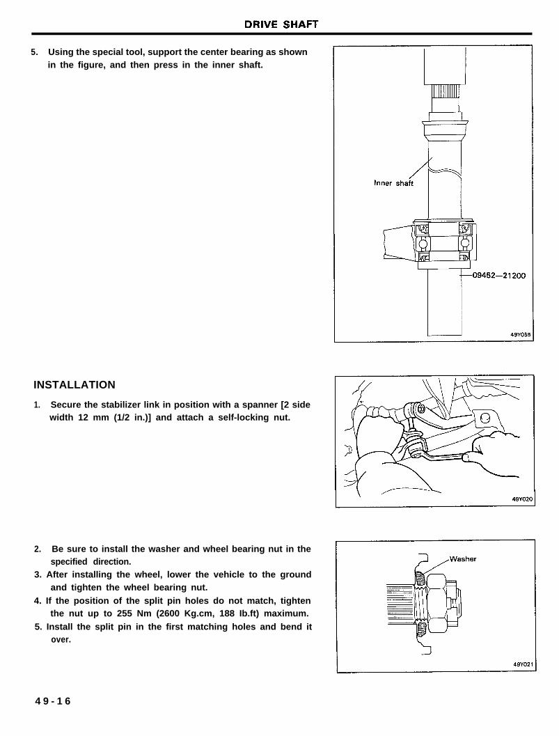
5. Using the special tool, support the center bearing as shownin the figure, and then press in the inner shaft.
INSTALLATION
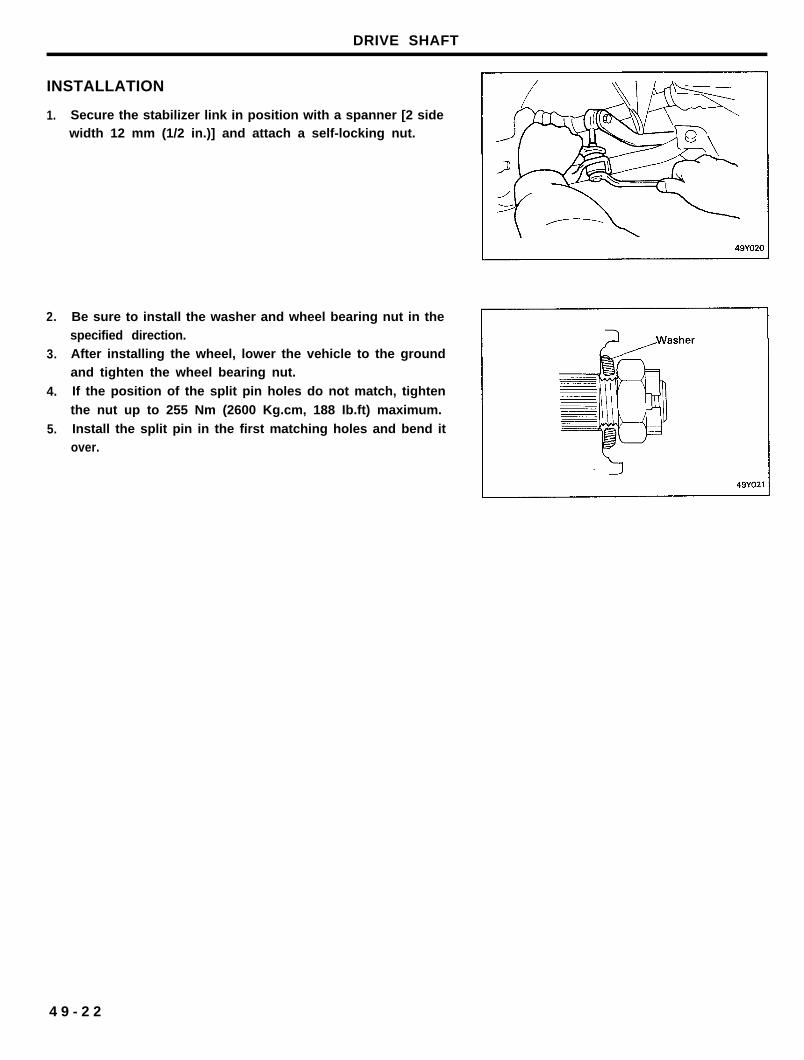
1. Secure the stabilizer link in position with a spanner [2 sidewidth 12 mm (1/2 in.)] and attach a self-locking nut.
2. Be sure to install the washer and wheel bearing nut in thespecified direction.
3. After installing the wheel, lower the vehicle to the groundand tighten the wheel bearing nut.
4. If the position of the split pin holes do not match, tightenthe nut up to 255 Nm (2600 Kg.cm, 188 Ib.ft) maximum.
5. Install the split pin in the first matching holes and bend itover.
4 9 - 1 6
DRIVE SHAFT
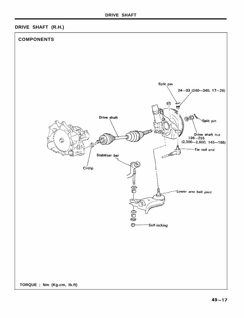
DRIVE SHAFT (R.H.)
COMPONENTS
TORQUE ; Nm (Kg.cm, Ib.ft)
DRIVE SHAFT
REPAIR KlTS
4 9 - 1 8
DRIVE SHAFT
REMOVAL
1. The removal procedure is the same as that of the drive shaft(L.H.).
2. Insert a pry bar between the transaxle case and the driveshaft, and then pry the drive shaft from the transaxle.
NOTE
Do not pull on the drive shaft; doing so will damage theD.O.J.; be sure to use the pry bar.
INSPECTION
1. Check the drive shaft boots for damage or deterioration.2. Check the ball joints for wear or operating condition.
3. Check the splines for wear or damage.
DISASSEMBLY AND ASSEMBLY
4 9 - 1 9
DRIVE SHAFT
DISASSEMBLY
1. Remove the snap ring, and then remove the D.O.J. innerrace, the D.O.J. cage, and the balls as a unit.
2. Clean the D.O.J. inner race, the D.O.J. cage, and the balls,without disassembling them.
NOTE1) Be careful that the balls do not drop out of the cage.2) If the balls drop out, press them back into the D.O.J.
cage with the D.O.J. inner race.
3. Wipe the grease off the spline portion.4. Remove he D.O.J. boot and B.J. boot.
NOTEIf the boots can be reused, wrap tape around the driveshaft splines so that the boots are not damaged when theyare removed.
NOTE
Do not disassemble the B.J..
Inspection after Disassembly
1. Inspect the drive shaft and drive shaft splines for wear,
damage, bending or corrosion.
2. Inspect the birfield joint for entry of water and/or foreignmaterial.
3. Check the double offset joint outer race, cage, balls and innerrace for damage, corrosion or wear.
ASSEMBLY
1. Wrap tape around the drive shaft splines (D.O.J. side) toprevent damage to the boots.
2. Apply grease to the drive shaft and install the boots.3. Remove the tape.
NOTEDistinguish between the B.J. boot and the D.O.J. boot
parts according to the section “Parts Distinction”, and besure to assemble them correctly.
4 9 - 2 0
DRIVE SHAFT
4. Fill the inside of the B.J. and B.J. boot with the specified
grease.
Recommended grease . . . . . . . . . . . . . . . . . . SUNLIGHT SW-2
5. Apply the recommended grease to the D.O.J. cage, the ballsand the D.O.J. inner race.
6. Fill the D.O.J. outer race with the recommended grease. Fitthe drive shaft into the D.O.J. outer race and apply additionalgrease to the D.O.J.‘s outer race.
7. Set the D.O.J. boot bands at the specified distance in orderto adjust the amount of air inside the D.O.J. boot, and thentighten the D.O.J. boot band securely.
Standard value. . . . . . . . . . . . . . . . . . . . . . . . . . . . . . . . . . . . . . . . .77.5±3 mm (3.05-10.12 in.)
4 9 - 2 1
DRIVE SHAFT
INSTALLATION
1.
2.
3.
4.
5.
Secure the stabilizer link in position with a spanner [2 sidewidth 12 mm (1/2 in.)] and attach a self-locking nut.
Be sure to install the washer and wheel bearing nut in thespecified direction.After installing the wheel, lower the vehicle to the groundand tighten the wheel bearing nut.
If the position of the split pin holes do not match, tighten
the nut up to 255 Nm (2600 Kg.cm, 188 Ib.ft) maximum.
Install the split pin in the first matching holes and bend itover.
4 9 - 2 2
HUB AND KNUCKLE
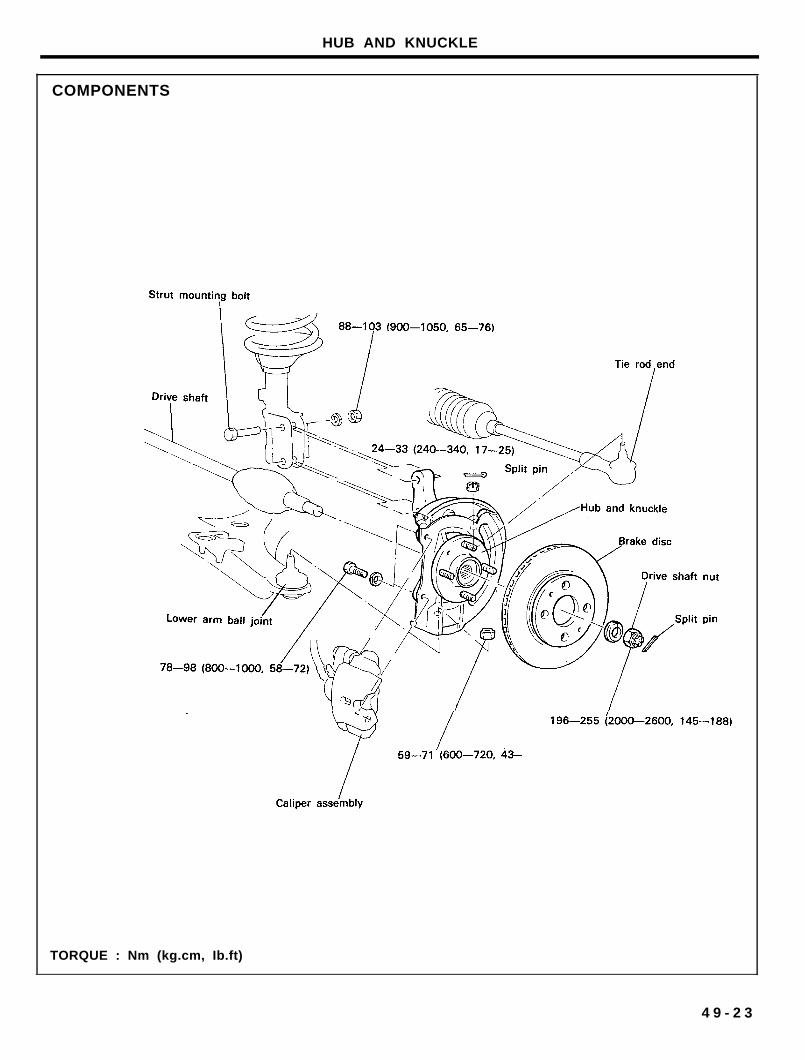
COMPONENTS
TORQUE : Nm (kg.cm, Ib.ft)
4 9 - 2 3
HUB AND KNUCKLE
REMOVAL
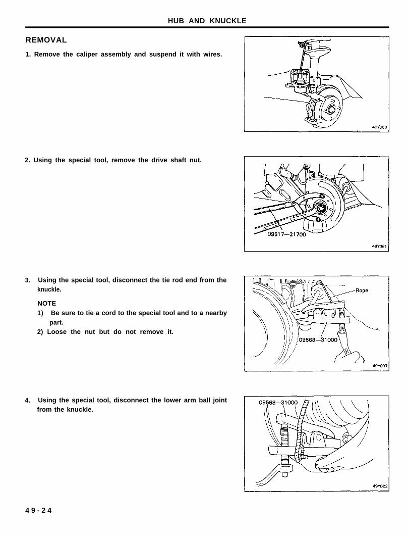
1. Remove the caliper assembly and suspend it with wires.
2. Using the special tool, remove the drive shaft nut.
3.
4.
Using the special tool, disconnect the tie rod end from theknuckle.
NOTE
1) Be sure to tie a cord to the special tool and to a nearby
part.2) Loose the nut but do not remove it.
Using the special tool, disconnect the lower arm ball jointfrom the knuckle.
4 9 - 2 4
HUB AND KNUCKLE
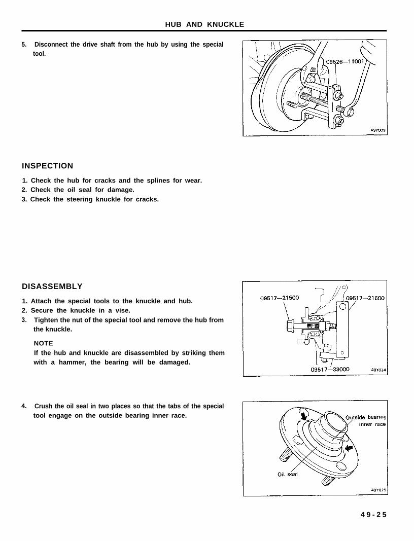
5. Disconnect the drive shaft from the hub by using the specialtool.
INSPECTION
1. Check the hub for cracks and the splines for wear.2. Check the oil seal for damage.
3. Check the steering knuckle for cracks.
DISASSEMBLY
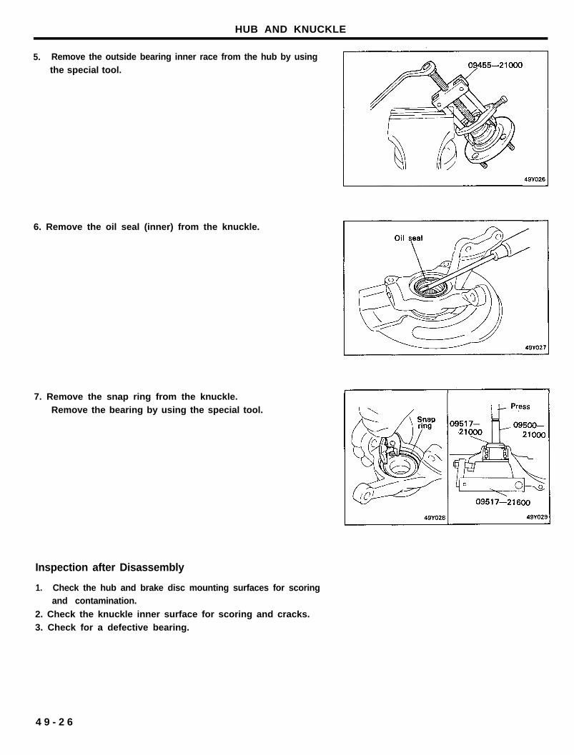
1. Attach the special tools to the knuckle and hub.2. Secure the knuckle in a vise.3. Tighten the nut of the special tool and remove the hub from
the knuckle.
NOTE
If the hub and knuckle are disassembled by striking themwith a hammer, the bearing will be damaged.
4. Crush the oil seal in two places so that the tabs of the specialtool engage on the outside bearing inner race.
4 9 - 2 5
HUB AND KNUCKLE
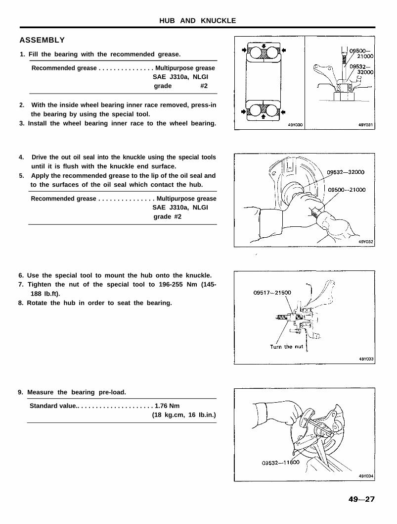
5. Remove the outside bearing inner race from the hub by usingthe special tool.
6. Remove the oil seal (inner) from the knuckle.
7. Remove the snap ring from the knuckle.Remove the bearing by using the special tool.
Inspection after Disassembly
1. Check the hub and brake disc mounting surfaces for scoringand contamination.
2. Check the knuckle inner surface for scoring and cracks.3. Check for a defective bearing.
4 9 - 2 6
HUB AND KNUCKLE
ASSEMBLY
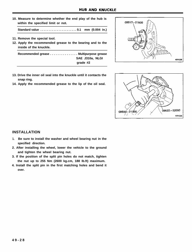
1. Fill the bearing with the recommended grease.
Recommended grease . . . . . . . . . . . . . . . Multipurpose greaseSAE J310a, NLGIgrade #2
2. With the inside wheel bearing inner race removed, press-inthe bearing by using the special tool.
3. Install the wheel bearing inner race to the wheel bearing.
4. Drive the out oil seal into the knuckle using the special toolsuntil it is flush with the knuckle end surface.
5. Apply the recommended grease to the lip of the oil seal andto the surfaces of the oil seal which contact the hub.
Recommended grease . . . . . . . . . . . . . . . Multipurpose greaseSAE J310a, NLGIgrade #2
6. Use the special tool to mount the hub onto the knuckle.7. Tighten the nut of the special tool to 196-255 Nm (145-
188 Ib.ft).8. Rotate the hub in order to seat the bearing.
9. Measure the bearing pre-load.
Standard value.. . . . . . . . . . . . . . . . . . . . . 1.76 Nm(18 kg.cm, 16 Ib.in.)
10. Measure to determine whether the end play of the hub iswithin the specified limit or not.
Standard value . . . . . . . . . . . . . . . . . . . . . . 0.1 mm (0.004 in.)
11. Remove the special tool.12. Apply the recommended grease to the bearing and to the
inside of the knuckle.
Recommended grease . . . . . . . . . . . . . . . Multipurpose greaseSAE J310a, NLGIgrade #2
13. Drive the inner oil seal into the knuckle until it contacts thesnap ring.
14. Apply the recommended grease to the lip of the oil seal.
INSTALLATION
1. Be sure to install the washer and wheel bearing nut in the
specified direction.2. After installing the wheel, lower the vehicle to the ground
and tighten the wheel bearing nut.3. If the position of the split pin holes do not match, tighten
the nut up to 255 Nm (2600 kg.cm, 188 Ib.ft) maximum.4. Install the split pin in the first matching holes and bend it
over.
4 9 - 2 8