Embed Size (px)
Citation preview

DRIVES

INTRODUCTION• Purpose of drives• Types of drives Dc drive Ac drive

SCR

ABOUT SCR• A thyristor is a four-layer
semiconductor device, consisting of alternating P type and N type materials (PNPN). A thyristor usually has three electrodes: an anode, a cathode, and a gate (control electrode).
• The most common type of thyristor is the silicon-controlled rectifier (SCR). When the cathode is negatively charged relative to the anode, no current flows until a pulse is applied to the gate. Then the SCR begins to conduct, and continues to conduct until the voltage between the cathode and anode is reversed or reduced below a certain threshold value. Using this type of thyristor, large amounts of power can be switched or controlled using a small triggering current or voltage.
• Thyristors are used in motor speed controls, light dimmers, pressure-control systems, and liquid-level regulators

SCR CHARACTERISTICS• Reverse
Blocking Mode
• Forward Blocking Mode
• Forward Conduction Mode

DC DRIVE
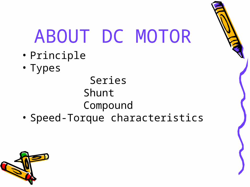
ABOUT DC MOTOR• Principle• Types Series Shunt Compound• Speed-Torque characteristics
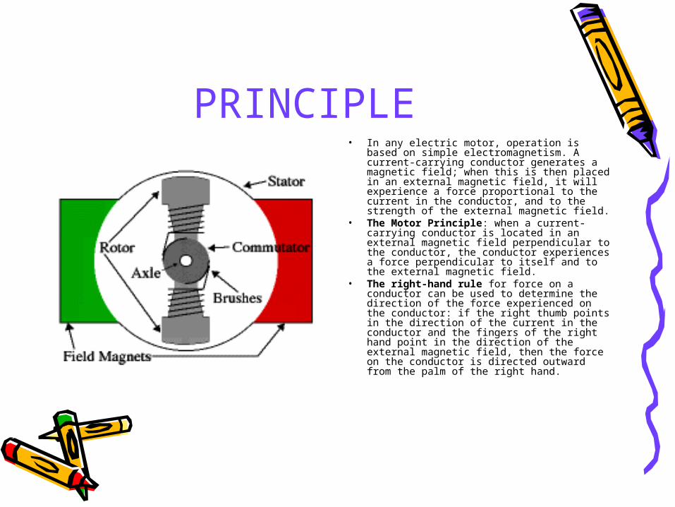
PRINCIPLE• In any electric motor, operation is based
on simple electromagnetism. A current-carrying conductor generates a magnetic field; when this is then placed in an external magnetic field, it will experience a force proportional to the current in the conductor, and to the strength of the external magnetic field.
• The Motor Principle: when a current-carrying conductor is located in an external magnetic field perpendicular to the conductor, the conductor experiences a force perpendicular to itself and to the external magnetic field.
• The right-hand rule for force on a conductor can be used to determine the direction of the force experienced on the conductor: if the right thumb points in the direction of the current in the conductor and the fingers of the right hand point in the direction of the external magnetic field, then the force on the conductor is directed outward from the palm of the right hand.


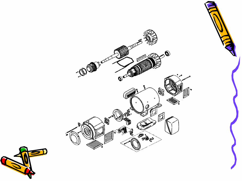
DC MOTOR COMPONENTS
• Motor frame (stator) tubular or laminated steel construction
• End bells (brackets)• Armature: Commutator, Laminations, Shaft
and bearings• Field coil and pole assemblies• Interpole coil and pole assemblies• Brush rigging: Brushes,Brush holders and
springs Rocker ring

BRUSH RIGGING
INTERPOLES
FIELDS
ARMATURE
BRACKETSFRAME
Fan

TYPES OF DC MOTOR
SHUNT MOTORS SERIES MOTOR
COMPOUND WOUND MOTORS

Speed-Torque characteristics

Speed-Torque charecteristics
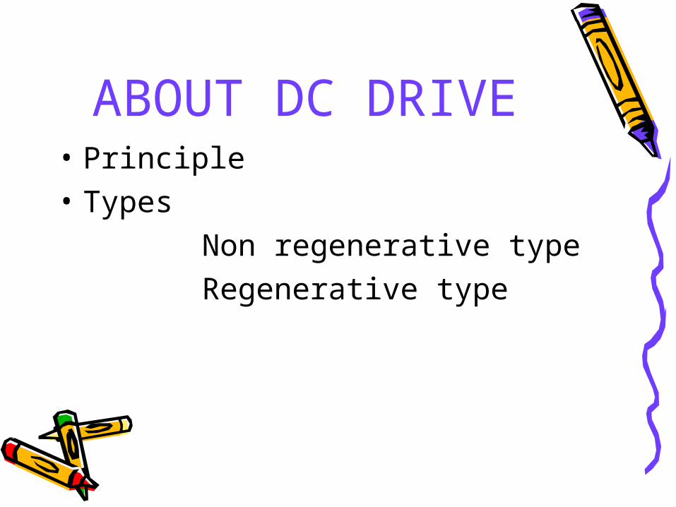
ABOUT DC DRIVE• Principle• Types Non regenerative type Regenerative type

Principle

Principle

Phase Angle control

Types

AC DRIVE/VFD

ABOUT INDUCTION MOTOR
• Principle• Speed-Torque characteristics
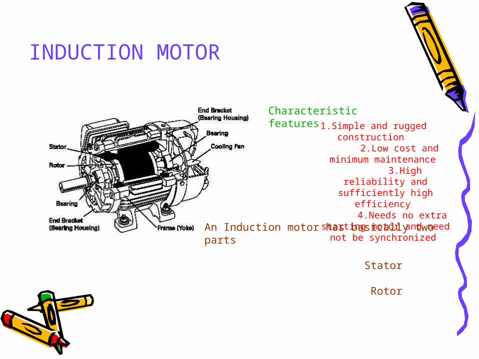
INDUCTION MOTOR
Characteristic features
1.Simple and rugged construction 2.Low cost and minimum
maintenance 3.High reliability and
sufficiently high efficiency 4.Needs no extra starting
motor and need not be synchronized
An Induction motor has basically two parts Stator Rotor
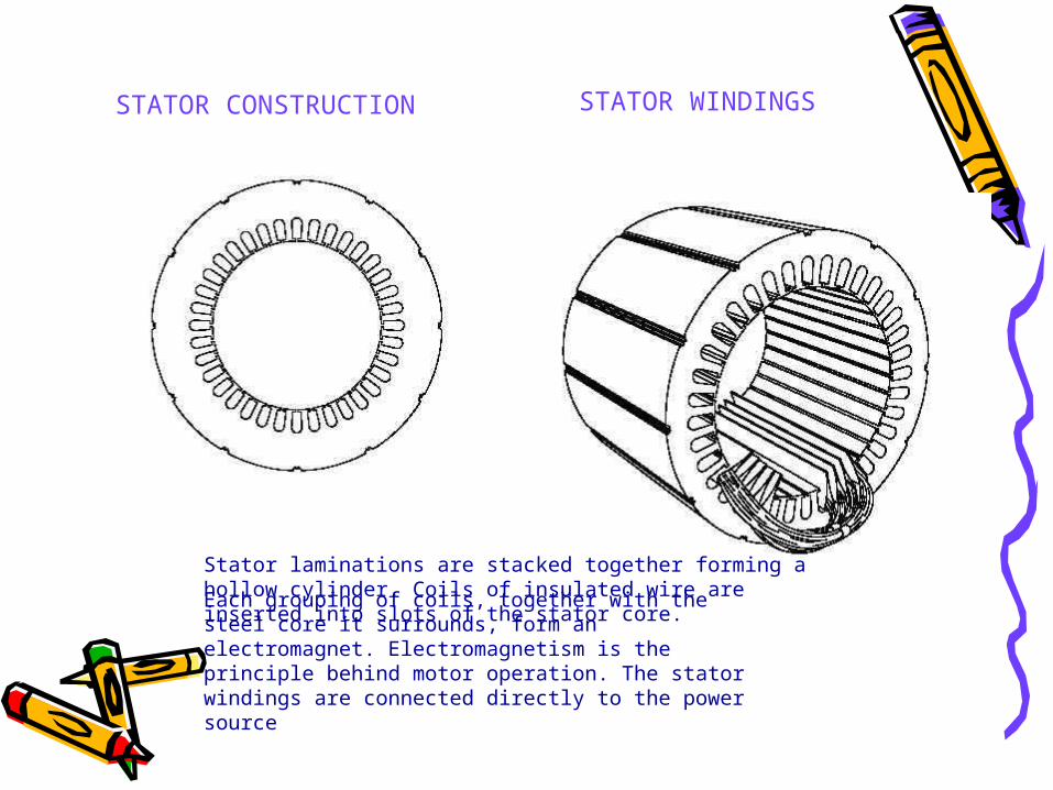
STATOR CONSTRUCTION STATOR WINDINGS
Stator laminations are stacked together forming a hollow cylinder. Coils of insulated wire are inserted into slots of the stator core. Each grouping of coils, together with the steel core it surrounds, form an electromagnet. Electromagnetism is the principle behind motor operation. The stator windings are connected directly to the power source

ROTOR CONSTRUCTION
The rotor consists of a stack of steel laminations with evenly spaced conductor bars around the circumference.
The laminations are stacked together to form a rotor core. Aluminum is die cast in the slots of the rotor core to form a series of conductors around the perimeter of the rotor. Current flow through the conductors form the electromagnet. The conductor bars are mechanically and electrically connected with end rings. The rotor core mounts on a steel shaft to form a rotor assembly
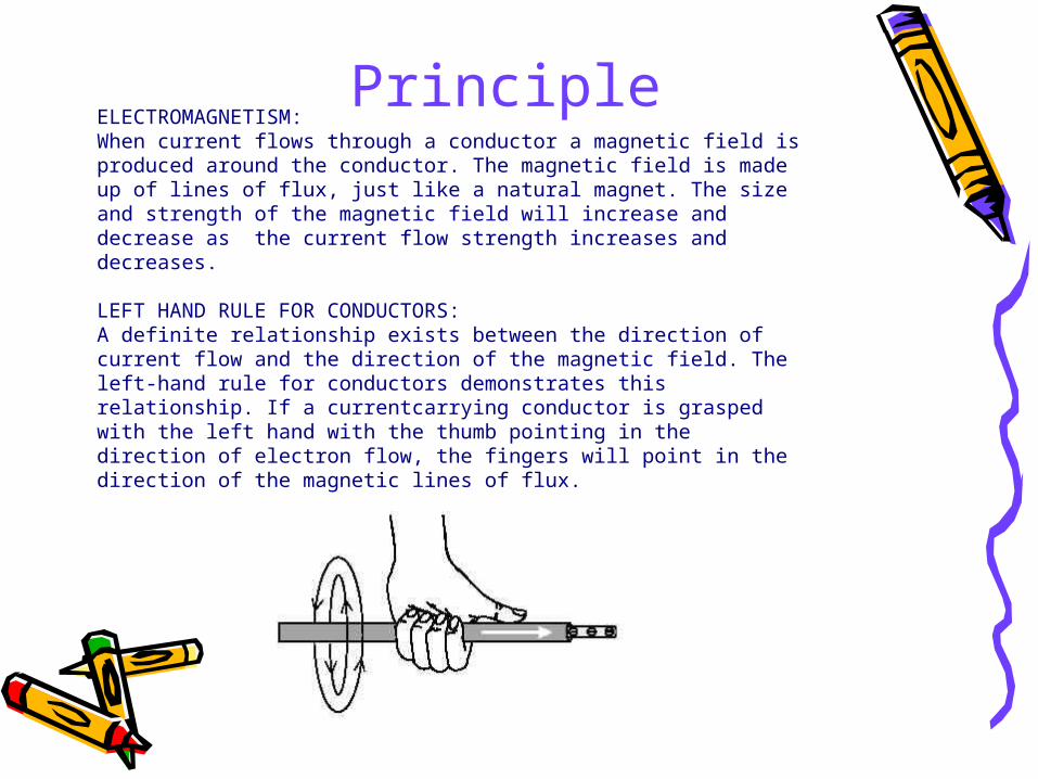
ELECTROMAGNETISM:When current flows through a conductor a magnetic field is produced around the conductor. The magnetic field is made up of lines of flux, just like a natural magnet. The size and strength of the magnetic field will increase and decrease as the current flow strength increases and decreases.
LEFT HAND RULE FOR CONDUCTORS:A definite relationship exists between the direction of current flow and the direction of the magnetic field. The left-hand rule for conductors demonstrates this relationship. If a currentcarrying conductor is grasped with the left hand with the thumb pointing in the direction of electron flow, the fingers will point in the direction of the magnetic lines of flux.
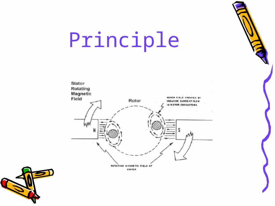
Principle
Principle

NO OF TURNS
CHANGING POLARITY

Speed-Torque characteristics

ABOUT VFD• Principle• Maintenance

Principle


VFD OUTPUT

VFD MAINTENANCEKeep it Clean Keep it Dry
Keep Connections Tight

DC DRIVE Vs VFD AC DRIVES MAY BE BETTER BECAUSE.. 1.They use conventional, low cost, 3-phase AC induction motors
for most applications
2.Multiple motors in a system must operate simultaneously at a
common frequency/speed DC DRIVES MAY BE BETTER BECAUSE.. 1.DC drives are less complex with a single power conversion
from AC to DC
2.DC regenerative drives are available for applications requiring continuous regeneration for overhauling loads. AC drives with this capability would be more complex and expensive


![[PPT] Title Subtitle - ABB · Web viewArial Wingdings Calibri blank 1_blank Replacement of BLK152 to BLK 222 Drive for LTB 145 D1/B Breaker Replacement of BLK152 Drive to BLK 222](https://img.pdfslide.us/doc/110x75/61097f13ad970c2f7f7865ef/ppt-title-subtitle-abb-web-view-arial-wingdings-calibri-blank-1blank-replacement.jpg)


![Utilizing GRADE/GMADE Data to Drive Instructionimages.pearsonassessments.com/images/PDF/Webinar/... · Microsoft PowerPoint - Ppt0000000.ppt [Read-Only] Author: lokksa Created Date:](https://img.pdfslide.us/doc/110x75/5f64919b043f1451b03c708b/utilizing-gradegmade-data-to-drive-microsoft-powerpoint-ppt0000000ppt-read-only.jpg)