Embed Size (px)
Citation preview

Drive Cage Upgrade Kit Installation Guide:Intel® Server Chassis SC5400 Order Number: D38448-004
This document provides instructions for installing the following accessory kits:
AXX4DRV3G
AXX6DRV3G
AXX4DRV3GEXP
AXX6DRV3GEXP

Disclaimer
Information in this document is provided in connection with Intel® products. No license, express or implied, by estoppel or otherwise, to any intellectual property rights is granted by this document. Except as provided in Intel's Terms and Conditions of Sale for such products, Intel assumes no liability whatsoever, and Intel disclaims any express or implied warranty, relating to sale and/or use of Intel products including liability or warranties relating to fitness for a particular purpose, merchantability, or infringement of any patent, copyright or other intellectual property right. Intel products are not designed, intended or authorized for use in any medical, life saving, or life sustaining applications or for any other application in which the failure of the Intel product could create a situation where personal injury or death may occur. Intel may make changes to specifications and product descriptions at any time, without notice.
Intel is a registered trademark of Intel Corporation or its subsidiaries in the United States and other countries.
* Other names and brands may be claimed as the property of others.
Copyright © 2005-2008 Intel Corporation. All Rights Reserved.
ii Important Safety Instructions
Important Safety Instructions Important Safety Instructions
Read all caution and safety statements in this document before performing any of the instructions. See Intel Server Boards and Server Chassis Safety Information at http://support.intel.com/support/motherboards/server/safecert.htm.
Wichtige Sicherheitshinweise
Lesen Sie zunächst sämtliche Warn- und Sicherheitshinweise in diesem Dokument, bevor Sie eine der Anweisungen ausführen. Beachten Sie hierzu auch die Sicherheitshinweise zu Intel-Serverplatinen und -Servergehäusen unter http://support.intel.com/support/motherboards/server/safecert.htm.
������
��������������������������������� http://support.intel.com/support/motherboards/server/sb/CS-010770.htm �� Intel Server Boards and Server Chassis Safety Information��Intel ������������������
Consignes de sécurité
Lisez attention toutes les consignes de sécurité et les mises en garde indiquées dans ce document avant de suivre toute instruction.Consultez Intel Server Boards and Server Chassis Safety Information rendez-vous sur le site http://support.intel.com/support/motherboards/server/safecert.htm.
Instrucciones de seguridad importantes
Lea todas las declaraciones de seguridad y precaución de este documento antes de realizar cualquiera de las instrucciones. Vea Intel Server Boards and Server Chassis Safety Information en http://support.intel.com/support/motherboards/server/safecert.htm.
Important Safety Instructions

Warnings and Cautions These warnings and cautions apply whenever you remove the access cover to access components inside the server. Only a technically qualified person should integrate and configure the server.
WARNINGS The power button on the front panel DOES NOT turn off the AC power. To remove power from server, you must unplug the AC power cord from the wall outlet or the chassis.
Hazardous electrical conditions may be present on power, telephone, and communication cables. Turn off the server and disconnect the power cords, telecommunications systems, networks, and modems attached to the server before opening it. Otherwise, personal injury or equipment damage can result.
Hazardous voltage, current, and energy levels are present inside the power supply. There are no user-serviceable parts inside it; servicing should be done by technically qualified personnel.
CAUTIONS ESD can damage disk drives, boards, and other parts. Perform all procedures in this document only at an ESD workstation. If one is not available, provide ESD protection by wearing an anti-static wrist strap attached to chassis ground⎯any unpainted metal surface⎯on your server when handling parts.
Always handle boards carefully. They can be extremely sensitive to ESD. Hold boards only by their edges. Do not touch the connector contacts. After removing a board from its protective wrapper or from the server, place the board component side up on a grounded, static free surface. Use a conductive foam pad if available but not the board wrapper. Do not slide board over any surface.
For proper cooling and airflow, always install the access cover before turning on the server. Operating it without the cover in place can damage system parts.
iv Warnings and Cautions

Contents Before You Begin ................................................................................................ 1
About the Drive Cage Upgrade Kits ........................................................................................ 1 Kit Contents Lists .................................................................................................................... 2 Tools and Supplies Needed.................................................................................................... 3 How to Use this Guide ............................................................................................................ 3
Intel® Server Chassis SC5400 Installation ....................................................... 4 Remove the Access Cover...................................................................................................... 4 Remove the Bezel Assembly .................................................................................................. 5 Remove Hot Swap Fans ......................................................................................................... 6 Four-drive Upgrade Drive Cage Installation............................................................................ 7 Make Backplane Cable Connections ...................................................................................... 9
For a four-drive expander backplane connect the following cables: .............................. 9 For a four-drive non-expander backplane connect the following cables: ..................... 10 For a four-drive SAS hot swap drive cage installation:................................................. 11
Six-drive Upgrade Drive Cage Installation ............................................................................ 12 Make Backplane Cable Connections .................................................................................... 14
For a six-drive SAS expander backplane installation: .................................................. 14 For a six-drive SAS/SATA backplane non-expander installation: ................................ 15
Make Server Board/RAID Controller Card Connections ....................................................... 15 Reinstall Hot Swap Fans....................................................................................................... 16 Install Hot Swap Hard Drives ................................................................................................ 16 Install Fixed Hard Drives ....................................................................................................... 16 Replace Bezel Assembly ...................................................................................................... 17 Replace Access Cover.......................................................................................................... 19
Contents

Figures Figure 1. Removing Access Cover.......................................................................................... 4 Figure 2. Removing Bezel Assembly ...................................................................................... 5 Figure 3. Removing Hot Swap Fans from Chassis ................................................................. 6 Figure 4. Removing Grill ......................................................................................................... 7 Figure 5. Installing Drive Cage into Chassis ........................................................................... 8 Figure 6. Making Four-drive Expander Fixed Drive Cage Cable Connections ....................... 9 Figure 7. Making Four-drive Non-expander Fixed Drive Cage Cable Connections .............. 10 Figure 8. Removing Six-drive Fixed Drive Cage from Chassis ............................................. 12 Figure 9. Installing Six-drive Hot Swap Drive Cage into Chassis.......................................... 13 Figure 10. Making Six-drive SAS Hot Swap Drive Cage Backplane Cable Connections ..... 14 Figure 11. Making Six-drive Non-expander SAS/SATA Hot Swap Drive Cage Backplane
Cable Connections....................................................................................................... 15 Figure 12. Reinstalling Hot Swap Fans................................................................................. 16 Figure 13. Reinstalling Bezel Assembly................................................................................ 18 Figure 14. Replacing Access Cover...................................................................................... 19
vi Contents
Before You Begin
Before removing the access cover for any reason, observe these safety guidelines.
1. Turn off any peripheral devices connected to the server. 2. Turn off the server by pressing the power button on the front of the chassis. 3. Unplug the AC power cord from the chassis or wall outlet. 4. Label and disconnect all peripheral cables connected to I/O connectors or ports on the back of
the chassis. 5. Label and disconnect all telecommunication lines connected to I/O connectors or ports on the
back of the chassis. 6. Provide electrostatic discharge (ESD) protection by wearing an anti-static wrist strap attached
to a chassis ground—any unpainted metal surface—when handling components.
About the Drive Cage Upgrade Kits Four- and six-drive cage upgrade kits allow you to install various hard drive solutions for the following Intel® Server Chassis: Intel® Server Chassis SC5400 Intel® Server Chassis SC5400 LX Intel® Server Chassis SC5400 Base Redundant Power (BRP)
NOTE Refer to your server board documentation to determine SAS/SATA support for your server system.
If you want to use your SAS/SATA drives for a RAID configuration, you may need to install a SAS/SATA RAID add-in card. Refer to your server board documentation and/or your SAS/SATA RAID card documentation for additional installation instructions and requirements.
Before You Begin
2 Before You Begin
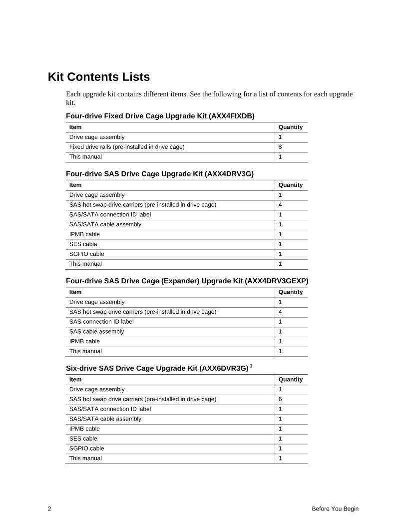
Kit Contents Lists Each upgrade kit contains different items. See the following for a list of contents for each upgrade kit.
Four-drive Fixed Drive Cage Upgrade Kit (AXX4FIXDB) Item Quantity Drive cage assembly 1 Fixed drive rails (pre-installed in drive cage) 8 This manual 1
Four-drive SAS Drive Cage Upgrade Kit (AXX4DRV3G) Item Quantity Drive cage assembly 1 SAS hot swap drive carriers (pre-installed in drive cage) 4 SAS/SATA connection ID label 1 SAS/SATA cable assembly 1 IPMB cable 1 SES cable 1 SGPIO cable 1 This manual 1
Four-drive SAS Drive Cage (Expander) Upgrade Kit (AXX4DRV3GEXP) Item Quantity Drive cage assembly 1 SAS hot swap drive carriers (pre-installed in drive cage) 4 SAS connection ID label 1 SAS cable assembly 1 IPMB cable 1 This manual 1
Six-drive SAS Drive Cage Upgrade Kit (AXX6DVR3G) 1 Item Quantity Drive cage assembly 1 SAS hot swap drive carriers (pre-installed in drive cage) 6 SAS/SATA connection ID label 1 SAS/SATA cable assembly 1 IPMB cable 1 SES cable 1 SGPIO cable 1 This manual 1

Before You Begin
Six-drive SATA Drive Cage (Expander) Upgrade Kit (AXX6DVR3GEXP) 1 Item Quantity Drive cage assembly 1 SAS/SATA hot swap drive carriers (pre-installed in drive cage) 6 SAS connection ID label 1 SAS cable assembly 1 IPMB cable 1 This manual 1
Tools and Supplies Needed • Phillips* (cross head) screwdriver (#2 bit) • Flat-head screwdriver • Anti-static wrist strap (recommended) • Needle-nosed pliers • Serial ATA RAID card (dependent on installation) • SAS RAID card (dependent on installation)
How to Use this Guide If you are installing drive cage upgrade kits into an Intel® Server Chassis SC5400, SC5400 Base Redundant Power (BRP) or SC5400 LX follow the instructions under the section titled “Intel® Server Chassis SC5400 Installation.”
For either chassis, if you are installing hot swap drives, follow the instructions under the section titled “Install Hot Swap Hard Drives”.
For the Intel® Server Chassis SC5400, if you are installing fixed drives, follow the instructions under the section titled “Install Fixed Hard Drives.”
Intel® Server Chassis SC5400 Installation
NOTE This section only applies to drive cage upgrade kit installations in the Intel® Server Chassis SC5400, SC5400 BRP, or SC5400 LX.
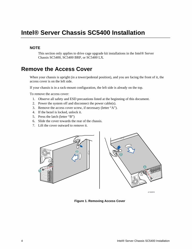
Remove the Access Cover When your chassis is upright (in a tower/pedestal position), and you are facing the front of it, the access cover is on the left side.
If your chassis is in a rack-mount configuration, the left side is already on the top.
To remove the access cover: 1. Observe all safety and ESD precautions listed at the beginning of this document. 2. Power the system off and disconnect the power cable(s). 3. Remove the access cover screw, if necessary (letter “A”). 4. If the bezel is locked, unlock it. 5. Press the latch (letter “B”) 6. Slide the cover towards the rear of the chassis. 7. Lift the cover outward to remove it.
Figure 1. Removing Access Cover
4 Intel® Server Chassis SC5400 Installation

Remove the Bezel Assembly The bezel assembly consists of two parts, an inner bezel door and an outer bezel door. Both parts comprise the bezel assembly in the pedestal configuration. In the rack configuration, only the inner bezel door is used.
NOTE For a rack configuration or chassis on its side, position the chassis hanging over the edge of a table or workbench before removing the bezel.
To remove the bezel assembly: 1. Release the two plastic tabs (letter “A”) on the left side of the bezel assembly to disengage the
tabs. 2. Rotate the bezel assembly (letter “B”) no more than 40 degrees outward. 3. At a 40-degree angle, push the bezel assembly away from the chassis (letter “C”). If the bezel
assembly does not immediately disconnect from the chassis, then tap the left-hand side of the bezel assembly to disengage the bezel hooks on the right-hand side of the chassis.
CAUTION Do not rotate the bezel assembly more than 40 degrees or you will damage the bezel hooks on the right-hand side of the bezel assembly.
Figure 2. Removing Bezel Assembly
Intel® Server Chassis SC5400 Installation 5

Remove Hot Swap Fans If your system is configured with hot swap fans, remove those hot swap fans that are positioned directly behind the drive cage(s) by completing the following steps:
1. Press the latch on the fan (letter “A”). 2. Pull on handle to remove from chassis.
Figure 3. Removing Hot Swap Fans from Chassis
6 Intel® Server Chassis SC5400 Installation

Four-drive Upgrade Drive Cage Installation Perform the following steps to install the following: Four-drive fixed drive cage Four-drive SAS hot swap drive cage (AXX4DRV3G or AXX4DRV3GEXP)
NOTE If you are performing a six-drive upgrade drive cage installation, refer to “Six-drive Upgrade Drive Cage Installation” for install instructions.
1. Loosen screw and remove the placeholder grill from the 4-drive bay slot of the chassis.
Figure 4. Removing Grill
Intel® Server Chassis SC5400 Installation 7

2. Slide the four-drive fixed or SAS drive cage into the 4-drive bay slot. You should hear a click when the blue plastic retention mechanism locks into place.
Figure 5. Installing Drive Cage into Chassis
8 Intel® Server Chassis SC5400 Installation

Make Backplane Cable Connections
For a four-drive expander backplane connect the following cables:
WARNING SATA Controllers cannot be used with expander backplanes.
1. Connect a power cable (letter “A”). 2. Connect data cable (letter “B”). 3. Connect IPMB cable (letter “C`”).
Figure 6. Making Four-drive Expander Fixed Drive Cage Cable Connections
Intel® Server Chassis SC5400 Installation 9

For a four-drive non-expander backplane connect the following cables:
1. Connect a power cable (letter “A”). 2. Connect data cable (letter “B”). 3. Connect SES cable (letter “C”). 4. Connect SGPIO cable (letter “D”). 5. Connect IPMB cable (letter “E”).
Figure 7. Making Four-drive Non-expander Fixed Drive Cage Cable Connections
10 Intel® Server Chassis SC5400 Installation
For a four-drive SAS hot swap drive cage installation: 1. Connect the SAS data cables from the server board to the SAS connectors on the SAS
backplane. 2. Connect two power cables to the power connectors on the SAS backplane. 3. Connect the HSBP_A header or HSBP_B header on the server board to the IPMB connector
on the SAS backplane. 4. Install the SES cable (AXX4DRV3GEXP only) 5. Connect the SES cable to the back plane. 6. Install the SGPIO cable (AXX4DRV3GEXP only) 7. Connect the SGPIO to the back plane.
Intel® Server Chassis SC5400 Installation 11

Six-drive Upgrade Drive Cage Installation Use these steps to install the following: Six-drive SAS Hot Swap Drive Cage (AXX6DRV3G or AXX6DRV3GEXP)
NOTE If you are performing a four-drive upgrade drive cage installation, refer to the section titled “Four-drive Upgrade Drive Cage Installation” for install instructions.
1. If hard drives are installed in the existing 6-drive fixed drive cage, disconnect the power and data
cables to each drive. 2. Push the blue plastic release mechanism (letter “A”) upward to release the existing drive cage. 3. Remove the existing drive cage from the 6-drive bay slot in chassis (letter “B”).
Figure 8. Removing Six-drive Fixed Drive Cage from Chassis
12 Intel® Server Chassis SC5400 Installation
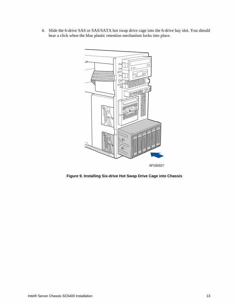
4. Slide the 6-drive SAS or SAS/SATA hot swap drive cage into the 6-drive bay slot. You should hear a click when the blue plastic retention mechanism locks into place.
Figure 9. Installing Six-drive Hot Swap Drive Cage into Chassis
Intel® Server Chassis SC5400 Installation 13

Make Backplane Cable Connections
WARNING It is critical that you connect the SAS/SATA data cables correctly from the SAS/SATA backplane to your server board or RAID Controller card. Failure to do so may result in data loss.
For a six-drive SAS expander backplane installation:
1. Connect two power cables (letter “A”) to the power cable connectors on the expander backplane.
2. Connect the SAS data cables (letter “B”) to each appropriate SAS connector on the SAS Expander backplane. When viewed from the front, the hard drives in the drive cage are labeled as the figure below indicates.
3. Connect IPMB (letter “C”)
Figure 10. Making Six-drive SAS Hot Swap Drive Cage Backplane Cable Connections
WARNING SATA Controllers cannot be used with expander backplanes.
14 Intel® Server Chassis SC5400 Installation

For a six-drive SAS/SATA backplane non-expander installation:
Figure 11. Making Six-drive Non-expander SAS/SATA Hot Swap Drive Cage Backplane Cable
Connections
1. Connect the power cables (letter “A”) 2. Connect the data cables (letter “B”) 3. Connect the IPMB cable (letter “C”) 4. Connect the SES cable (letter “D”) 5. Connect the SGPIO cable (letter “E”)
Make Server Board/RAID Controller Card Connections Refer to the documentation that came with your server board and/or RAID Controller card for instructions on connecting backplane cables to your server board or RAID Controller card.
WARNING It is critical that you connect the SAS/SATA data cables correctly from the SAS/SATA backplane to your server board or RAID Controller card. Failure to do so may result in data loss.
NOTE Connect the SES connector on the backplane to the RAID card (if one is installed).
Intel® Server Chassis SC5400 Installation 15

Reinstall Hot Swap Fans If previously removed, reinstall the hot swap fans into their respective positions in the chassis.
Figure 12. Reinstalling Hot Swap Fans
Install Hot Swap Hard Drives Install SAS or SATA hard disks drives into the four-drive cage or six-drive cage.
Install Fixed Hard Drives Install SAS or SATA hard disks drives into the four-drive cage or six-drive cage.
16 Intel® Server Chassis SC5400 Installation

Replace Bezel Assembly 1. For a pedestal-configured system, open the outer bezel door of the bezel assembly (letter “A”).
NOTE Both the outer bezel door and inner bezel door are used when the chassis is configured for the pedestal position. For rack-configured systems, only the inner bezel door is used.
2. For both pedestal- and rack-configured systems, remove all filler panels from the inner bezel door that correspond to installed drive cage(s).
3. For pedestal-configured systems, close the outer bezel door (letter “B”).
4. Fit the right edge of the bezel assembly against the right side of chassis and engage plastic bezel hooks (letter “C”) into raised metal slots at chassis edge.
CAUTION Do not attach bezel assembly to chassis at more than a 40-degree angle or you will damage the bezel hooks on the right side of the bezel assembly.
5. Rotate bezel assembly toward chassis and latch the two plastic tabs (letter “D”) on left side of
bezel assembly to chassis.
Intel® Server Chassis SC5400 Installation 17

Figure 13. Reinstalling Bezel Assembly
18 Intel® Server Chassis SC5400 Installation

Replace Access Cover 1. Slide access cover on chassis. 2. Replace access cover screw (optional – see letter “A”).
Figure 14. Replacing Access Cover
CAUTION This chassis must be operated with the access cover installed to ensure proper cooling.
Intel® Server Chassis SC5400 Installation 19