Embed Size (px)
Citation preview
Drilling Characteristics of Bulk Metallic Glass inVarious Cooling ConditionsZhiyu Hu
Guangdong University of Technology, Guangzhou 510006, PR ChinaCheng Yong Wang ( [email protected] )
Guangdong University of TechnologyFeng Ding
Guangdong University of Technology, Guangzhou 510006, PR ChinaTao Zhang
Guangdong University of Technology, Guangzhou 510006, PR ChinaLijuan Zheng
Guangdong University of Technology, Guangzhou 510006, PR ChinaXuguang Zhu
Guangdong University of Technology, Guangzhou 510006, PR China
Research Article
Keywords: Bulk metallic glass, drilling, machinability
Posted Date: April 28th, 2021
DOI: https://doi.org/10.21203/rs.3.rs-375743/v1
License: This work is licensed under a Creative Commons Attribution 4.0 International License. Read Full License
Drilling characteristics of bulk metallic glass in various cooling condit
ions
Zhiyu Hu, Chengyong Wang *, Feng Ding, Tao Zhang, Lijuan Zheng, Xuguang Zhu a Guangdong University of Technology, Guangzhou 510006, PR China
* Correspondence to: Institute of Manufacturing Technology, Guangdong University of Technology, 510006 Guangzhou, PR China. Tel.: +86 20
39322206; Fax: +86 20 39322206. E-mail addresses: [email protected], [email protected] (C.Y. Wang).
Abstract
Drilling is an indispensable machining operation for manufacturing bulk metallic glass (BMG) medical appliances, which generally have complicated shapes and require high dimensional accuracy. Unfortunately, the available research on the drilling of BMG is limited, and thus reliable guidelines for practical production are lacking. For this reason, this paper focuses on the BMG machinability in the industrial range. The high-speed drillings of BMG specimens were carried out in dry, wet (cutting fluid), and frozen (icing clamp) conditions. The relationship between the thrust force, torque, drilling energy, tool life, tool wear, as well as the hole quality (burrs, diameter deviation, taper angle, and circularity) were studied. The cooling methods and matching spindle speeds were optimized, and the investigation has shown that wet drilling with high spindle speed is the most suitable method for machining BMG as it resulted in the longest tool life and the highest hole quality. Tool failure modes for all cooling methods included plastic deformation and rake face abrasions, in addition to the abrasive and adhesive wear on flank face. The chip adhesion to the entry hole was identified as the primary cause for the large entry burr. Finally, the crown-shaped exit burr rupture triggered the warpage and tearing of the material around the hole.
Keywords: Bulk metallic glass, drilling, machinability
1. Introduction
Bulk metallic glasses (BMGs) are a new type of metal having a disordered topological arrangement of atoms, without crystal defects, such as grain boundaries, stacking faults, and cavities [1, 2]. This unique amorphous structure makes them more suitable for manufacturing surgical instruments and implants than stainless steel, pure titanium, titanium alloys (Ti alloys), and similar biomedical polycrystalline metals. For example [3–5], the BMG tensile strengths are generally two to three times that of stainless steel and Ti alloys. Furthermore, the elastic limit in crystalline metals (approximately 0.65%) is three times lower than that of BMGs (2%). The BMG elastic moduli are as low as 70 to 100 GPa, closer to the human bone than Ti alloys. As such, they are better at reducing stress through shielding effects when implanted into a human body. In addition to mechanical properties, they are remarkably corrosion-resistant and biocompatible. Therefore, due to their inherent advantages, BMGs are considered ideal biomedical metals and have received extensive attention in both the engineering and medicine.
When it comes to producing BMG parts, high pressure die casting technology is the primary method in the industry [6–8]. However, medical appliances such as surgical instruments and implants usually have a complex shape and high require dimensional accuracy [9, 10]. making mechanical machining necessary. However, the metastable BMGs are strongly sensitive to temperature, and are typical of difficult-to-cut materials [11, 12]. The resulting cutting deformation is responsible for the unique characteristics of glassy materials, such as the lamellar chip formation at low cutting speeds, the viscous flow, crystallization, oxidation, melting, and chip light emission at relatively high cutting speeds. During the BMG machining, the cutting force frequently fluctuates, and the cutting tool is subjected to severe adhesive wear. Moreover, a relatively high cutting speed will, in turn, produce a very high cutting temperature, primarily due to the extremely low thermal conductivity of BMGs. This will often lead to crystallization of the machined surface, causing the material to lose its original amorphous nature.
In a previous study [13], orthogonal cutting tests were carried out to analyze the chip deformation behavior and the associated energy distribution in BMG machining. Increasing the cutting area heat dissipation and reducing the friction between tool and chip were expected to be primary methods for improving the BMG machinability. On this basis, a freezing-assisted BMG milling method was proposed, enabling the successful non-crystallized machining of BMG in a wide cutting speed range and at a large feed rate. As a result, low surface roughness was achieved [14].
This work extends the research on BMG machining, on the cutting mechanism, milling process, and drilling process. Although the non-traditional machining methods, such as laser or electrical discharge machining, are also used for hole making, they mostly rely on high energy to remove the material. However, applying high energy might result in workpiece crystallization or cause severe machining defects when processing BMG [15, 16]. Therefore, mechanical drilling remains the primary method for the manufacturing of BMG holes in practice.
During the drilling of BMGs, cutting speed, feed rate and tool material significantly influence the chip morphology, burr formation, machining luminescence, and tool wear. Bakkal et al. [17, 18] found that six different types of chips were produced in dry drilling of Zr52.5Ti5Cu17.9Ni14.6Al10 BMG. Depending on the cutting parameters and tool materials, unique large entry and exit burrs had the dominant effect on the BMG hole quality; the chip light emission worsened the burrs while possibly ablating the holes. Furthermore, regarding the chip light emission, the low thermal conductivity of the tool and high spindle speed were the key influencing factors. Compared to the high-speed steel (HSS) drill, the WC-
Co drill with higher thermal conductivity mitigated the light emission; therefore, it was a better choice for BMG drilling. It should also be noted that, HSS and WC-Co tools had comparable cutting performance in drilling without light emission.
Similar results were also observed when dry drilling of Zr57.5Cu11.2Ni13.8Al17.5 BMG, as presented by Tariq et al. [19], who concluded out that low feed rate might cause the WC-Co drill to break without drilling a hole. Zhu et al. [20] observed the same phenomenon in micro-drilling of Zr41.2Ti13.8Cu12.5Ni10Be22.5 BMG; the cutting shifted from the shear-dominated to the ploughing-dominated regime, depending on the minimum chip thickness. That eventually led to drilling instability and large burrs as the temperature rose, causing BMG state to change from the amorphous to the supercooled liquid state. Therefore, the hole material exhibited viscous characteristics, which made the tool wear to be dominated by the rake wear. Finally, Kuriakose et al. [21] studied the high temperature, light emission, and large burrs in BMG conventional drilling and introduced the micro ultrasonic machining technology into micro-drilling of BMG. This technology allowed removing the materials in a smaller volume, thus improving the BMG machinability and hole size accuracy.
Current research on BMGs drilling focused on dry cutting condition, which makes them exhibit poor machinability. In practical manufacturing, cutting fluid is needed to improve the machinability of the material, but the drilling technology on BMGs is still in the exploration stage, lacking process guidance. In this work, an investigation has been conducted to understand the machinability of BMG in the industrial range. The drilling operations for BMG were carried out at dry and wet conditions. In addition, the freezing-assisted machining technology previously used for the milling of BMG has also been extended to the drilling. The dynamic variations of the thrust force and torque of BMG with the drilling situation were analyzed. The influences of spindle speed and cooling method on thrust force, torque and energy were also investigated. The life and failure mode of tool were discussed. Proper cooling method and corresponding spindle speed for drilling BMG were optimized by evaluating tool life and hole quality (i.e. entry/exit burrs, diameter deviation, taper and circularity).
2. Experimental procedures
2.1 Workpiece materials
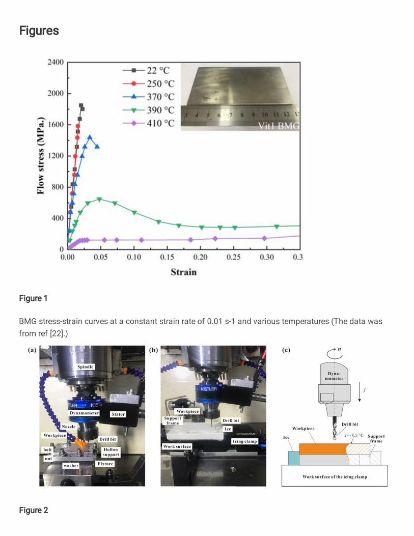
In this paper, the workpiece was made of classic Zr41.2Ti13.8Cu12.5Ni10Be22.5 (Vit1) BMG. The shape was rectangular plate with (100mm×50mm×2 mm), provided by Eontech New Materials Co., Ltd. and the preparation method available from the literature [6]. Moreover, the BMG stress-strain curves at a constant strain rate of 0.01 s-1 and various temperatures are shown in Fig. 1 [22], while the remaining mechanical and thermal properties of BMG were listed in

Table 1.
Fig. 1 BMG stress-strain curves at a constant strain rate of 0.01 s-1 and various temperatures (The data was from ref [22].)
Table 1 Mechanical and thermal properties of BMG.
Material Elastic
modulus (Gpa)
Elastic limit
Ultimate tensile
strength (Mpa)
Specific heat
(J/(kg∙K))
Thermal conductivity (W/(m∙K))
Coefficient of linear thermal
expansion (10-6/K)
Glass transition
temperature
(°C)
Crystallization temperature
(°C)
Melting temperature
(°C)
Vit1 BMG 101.2 2% 1900 420 4 8.8±0.64 at 20–426 °C
350 426 714
2.2 Experimental design
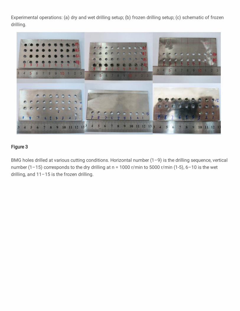
Fig. 2 illustrates the experimental setup for the workpiece drilling at dry, wet, and frozen conditions. Under dry and wet drilling conditions, the workpiece plate was fixed to the customized hollow support using bolts, nuts, and washers (see Fig. 2(a)). The cutting fluid (Mobilmet 427, ISO VG32) was used during the wet drilling. The icing clamp was used in the frozen drilling operation, as shown in Fig. 2(b). For more detailed introduction to the icing clamp, please see [14]. A 2 mm thick support frame was used to separate the workpiece and the icing clamp, primarily to avoid damaging the work surface when the drill bit is drilled out of the hole. Fig. 2(c) shows the workpiece fixing schema for the frozen drilling conditions. Before processing, the inner and outer sides of the support frame were filled with water, and the workpiece was placed on it. The icing clamp was opened to freeze the water, and after which the workpiece was fixed. The frozen workpiece surface temperature was approximately -8.5 ºC.
Fig. 2 Experimental operations: (a) dry and wet drilling setup; (b) frozen drilling setup; (c) schematic of frozen drilling.
All the drilling operations were carried out using a DMG/MORISEIKI MILLTAP 700 machining center. Since there
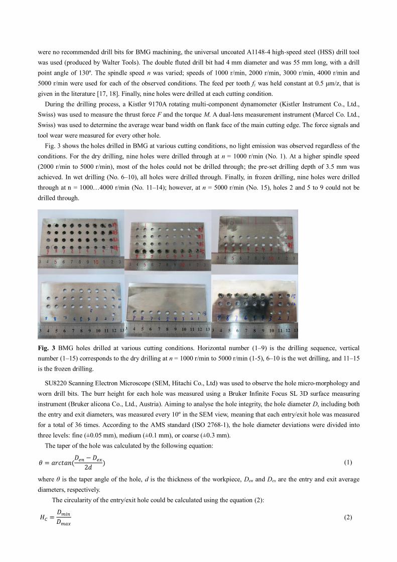
were no recommended drill bits for BMG machining, the universal uncoated A1148-4 high-speed steel (HSS) drill tool was used (produced by Walter Tools). The double fluted drill bit had 4 mm diameter and was 55 mm long, with a drill point angle of 130º. The spindle speed n was varied; speeds of 1000 r/min, 2000 r/min, 3000 r/min, 4000 r/min and 5000 r/min were used for each of the observed conditions. The feed per tooth fz was held constant at 0.5 μm/z, that is given in the literature [17, 18]. Finally, nine holes were drilled at each cutting condition.
During the drilling process, a Kistler 9170A rotating multi-component dynamometer (Kistler Instrument Co., Ltd., Swiss) was used to measure the thrust force F and the torque M. A dual-lens measurement instrument (Marcel Co. Ltd., Swiss) was used to determine the average wear band width on flank face of the main cutting edge. The force signals and tool wear were measured for every other hole.
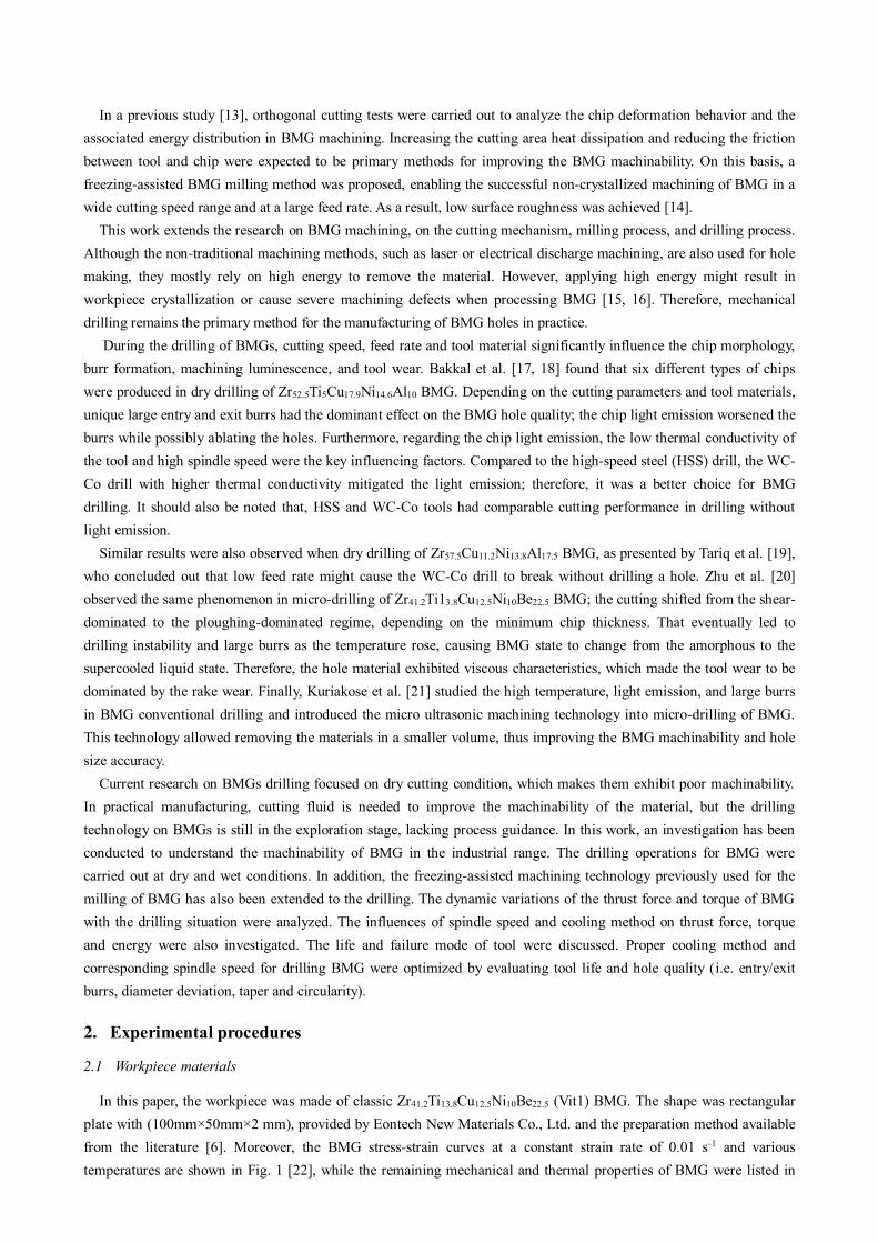
Fig. 3 shows the holes drilled in BMG at various cutting conditions, no light emission was observed regardless of the conditions. For the dry drilling, nine holes were drilled through at n = 1000 r/min (No. 1). At a higher spindle speed (2000 r/min to 5000 r/min), most of the holes could not be drilled through; the pre-set drilling depth of 3.5 mm was achieved. In wet drilling (No. 6–10), all holes were drilled through. Finally, in frozen drilling, nine holes were drilled through at n = 1000…4000 r/min (No. 11–14); however, at n = 5000 r/min (No. 15), holes 2 and 5 to 9 could not be drilled through.
Fig. 3 BMG holes drilled at various cutting conditions. Horizontal number (1–9) is the drilling sequence, vertical number (1–15) corresponds to the dry drilling at n = 1000 r/min to 5000 r/min (1-5), 6–10 is the wet drilling, and 11–15 is the frozen drilling.
SU8220 Scanning Electron Microscope (SEM, Hitachi Co., Ltd) was used to observe the hole micro-morphology and worn drill bits. The burr height for each hole was measured using a Bruker Infinite Focus SL 3D surface measuring instrument (Bruker alicona Co., Ltd., Austria). Aiming to analyse the hole integrity, the hole diameter D, including both the entry and exit diameters, was measured every 10º in the SEM view, meaning that each entry/exit hole was measured for a total of 36 times. According to the AMS standard (ISO 2768-1), the hole diameter deviations were divided into three levels: fine (±0.05 mm), medium (±0.1 mm), or coarse (±0.3 mm).
The taper of the hole was calculated by the following equation: 𝜃 = 𝑎𝑟𝑐𝑡𝑎𝑛(𝐷𝑒𝑛 − 𝐷𝑒𝑥2𝑑 ) (1)
where θ is the taper angle of the hole, d is the thickness of the workpiece, Den and Dex are the entry and exit average diameters, respectively.
The circularity of the entry/exit hole could be calculated using the equation (2): 𝐻𝐶 = 𝐷𝑚𝑖𝑛𝐷𝑚𝑎𝑥 (2)
where Hc was the circularity of entry/exit hole, Dmin and Dmax were the measured maximum and minimum diameters of entry/exit hole, respectively.
3. Comparison of thrust force, torque and drilling energy between BMG and titanium alloy
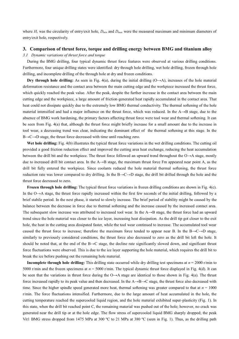
3.1 Dynamic variations of thrust force and torque During the BMG drilling, four typical dynamic thrust force features were observed at various drilling conditions.
Furthermore, four unique drilling states were identified: dry through hole drilling, wet hole drilling, frozen through hole drilling, and incomplete drilling of the through hole at dry and frozen conditions.
Dry through hole drilling: As seen in Fig. 4(a), during the initial drilling (O→A), increases of the hole material deformation resistance and the contact area between the main cutting edge and the workpiece increased the thrust force, which quickly reached the peak value. After the peak, despite the further increase in the contact area between the main cutting edge and the workpiece, a large amount of friction-generated heat rapidly accumulated in the contact area. That heat could not dissipate quickly due to the extremely low BMG thermal conductivity. The thermal softening of the hole material intensified and had a major influence on the thrust force, which was reduced. In the A→B stage, due to the absence of BMG work hardening, the primary factors affecting thrust force were tool wear and thermal softening. It can be seen from Fig. 4(a) that, although the thrust force might briefly increase for a small amount due to the increase in tool wear, a decreasing trend was clear, indicating the dominant effect of the thermal softening at this stage. In the B→C→D stage, the thrust force decreased with time until reaching zero.
Wet hole drilling: Fig. 4(b) illustrates the typical thrust force variations in the wet drilling conditions. The cutting oil provided a good friction reduction effect and improved the cutting area heat exchange, reducing the heat accumulation between the drill bit and the workpiece. The thrust force followed an upward trend throughout the O→A stage, mostly due to increased drill bit contact area. In the A→B stage, the maximum thrust force Fm appeared near point A, as the drill bit fully entered the workpiece. Since coolants reduced the hole material thermal softening, the thrust force reduction rate was lower compared to dry drilling. In the B→C→D stage, the drill bit drilled through the hole and the thrust force decreased to zero.
Frozen through hole drilling: The typical thrust force variations in frozen drilling conditions are shown in Fig. 4(c). In the O→A stage, the thrust force rapidly increased within the first few seconds of the initial drilling, followed by a brief stabile period. In the next phase, it started to slowly increase. The brief period of stability might be caused by the balance between the decrease in force due to thermal softening and the increase caused by the increased contact area. The subsequent slow increase was attributed to increased tool wear. In the A→B stage, the thrust force had an upward trend since the hole material was closer to the ice layer, increasing heat dissipation. As the drill tip got closer to the exit hole, the heat in the cutting area dissipated faster, while the tool wear continued to increase. The accumulated tool wear caused the thrust force to increase; therefore the maximum force tended to appear near B. In the B→C→D stage, similarly to previously considered conditions, the thrust force also decreased to zero as the drill bit left the hole. It should be noted that, at the end of the B→C stage, the decline rate significantly slowed down, and significant thrust force fluctuations were observed. This is due to the ice layer supporting the hole material, which requires the drill bit to break the ice before pushing out the remaining hole material.
Incomplete through hole drilling: This drilling state occurred while dry drilling test specimens at n = 2000 r/min to 5000 r/min and the frozen specimens at n = 5000 r/min. The typical dynamic thrust force displayed in Fig. 4(d). It can be seen that the variations in thrust force during the O→A stage are identical to those shown in Fig. 4(a). The thrust force increased rapidly to its peak value and then decreased. In the A→B→C stage, the thrust force also decreased with time. Since the higher spindle speed generated more heat, thermal softening was greater compared to that at n = 1000 r/min. The force fluctuations intensified. Furthermore, due to the large amount of heat accumulated in the hole, the cutting temperature reached the supercooled liquid region, and the hole material exhibited super-plasticity (Fig. 1). In this state, when the drill bit reached point C, the remaining material was pushed out of the hole; however, no crack was generated near the drill tip or at the hole edge. The flow stress of supercooled liquid BMG sharply dropped; the peak Vit1 BMG stress dropped from 1475 MPa at 300 ºC to 21 MPa at 380 ºC (seen in Fig. 1). Thus, as the drilling path
increased and the drill bit continuously squeezed the remaining superplastic hole material with minimal thrust force (C→D stage), until reaching the preset drilling depth. The hole was unable to be drilled through.
To sum up, the thrust force in BMG drilling was significantly affected by both the cooling method and spindle speed. The thermal softening effect was more prominent at dry drilling conditions compared to wet and frozen drilling, which resulted in a peak thrust force occurring before the main cutting edge is fully involved in the cutting. Regardless of the cooling method, thrust force was dominated by tool wear accumulation and thermal softening. Additionally, in dry and frozen drilling operations with high spindle speed, the hole in the supercooled liquid state could not be drilled through. Therefore, the thrust force could not drop to zero at the end of the operation.
Fig. 4 Typical dynamic variation of thrust force during BMG drilling: (a) dry through hole drilling; (b) wet hole drilling; (c) frozen through hole drilling; (d) incomplete through hole drilling.
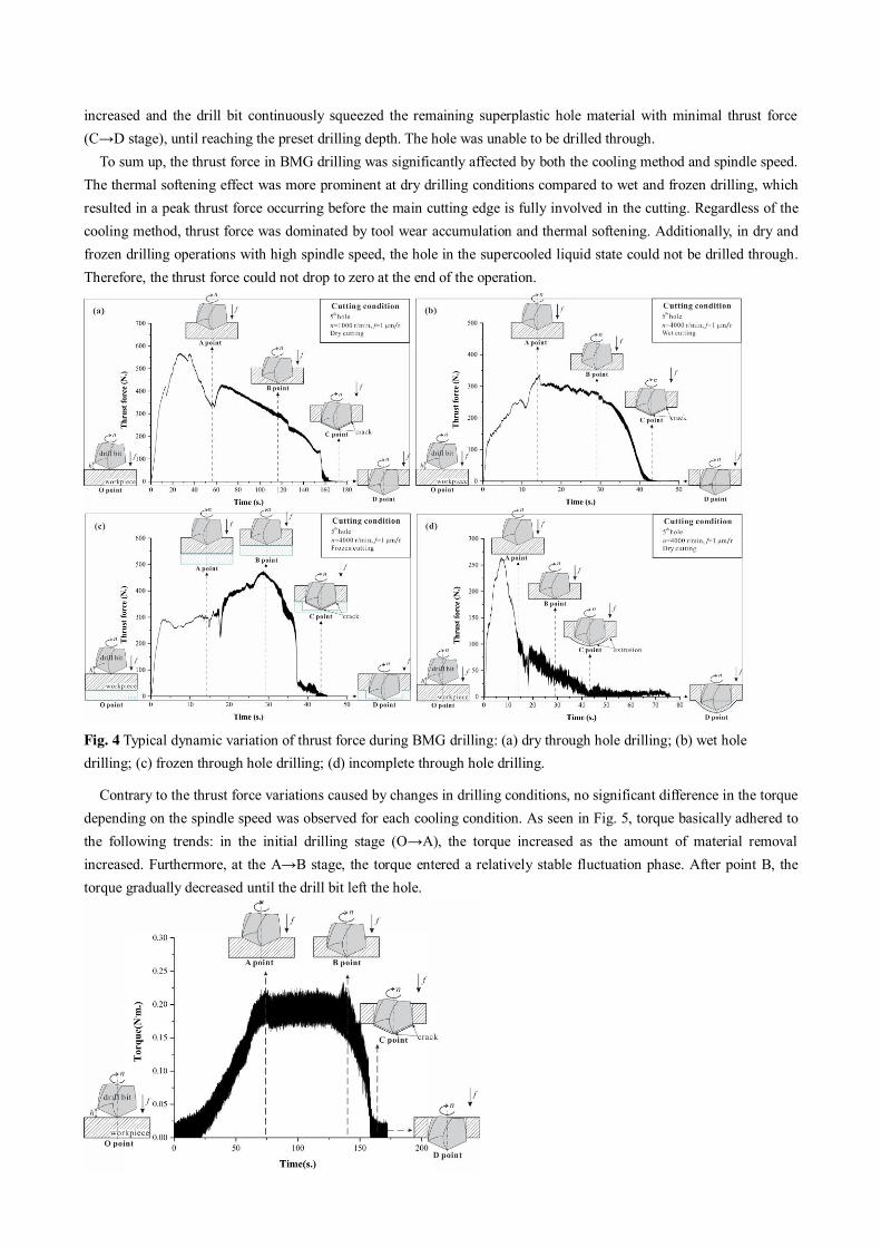
Contrary to the thrust force variations caused by changes in drilling conditions, no significant difference in the torque depending on the spindle speed was observed for each cooling condition. As seen in Fig. 5, torque basically adhered to the following trends: in the initial drilling stage (O→A), the torque increased as the amount of material removal increased. Furthermore, at the A→B stage, the torque entered a relatively stable fluctuation phase. After point B, the torque gradually decreased until the drill bit left the hole.
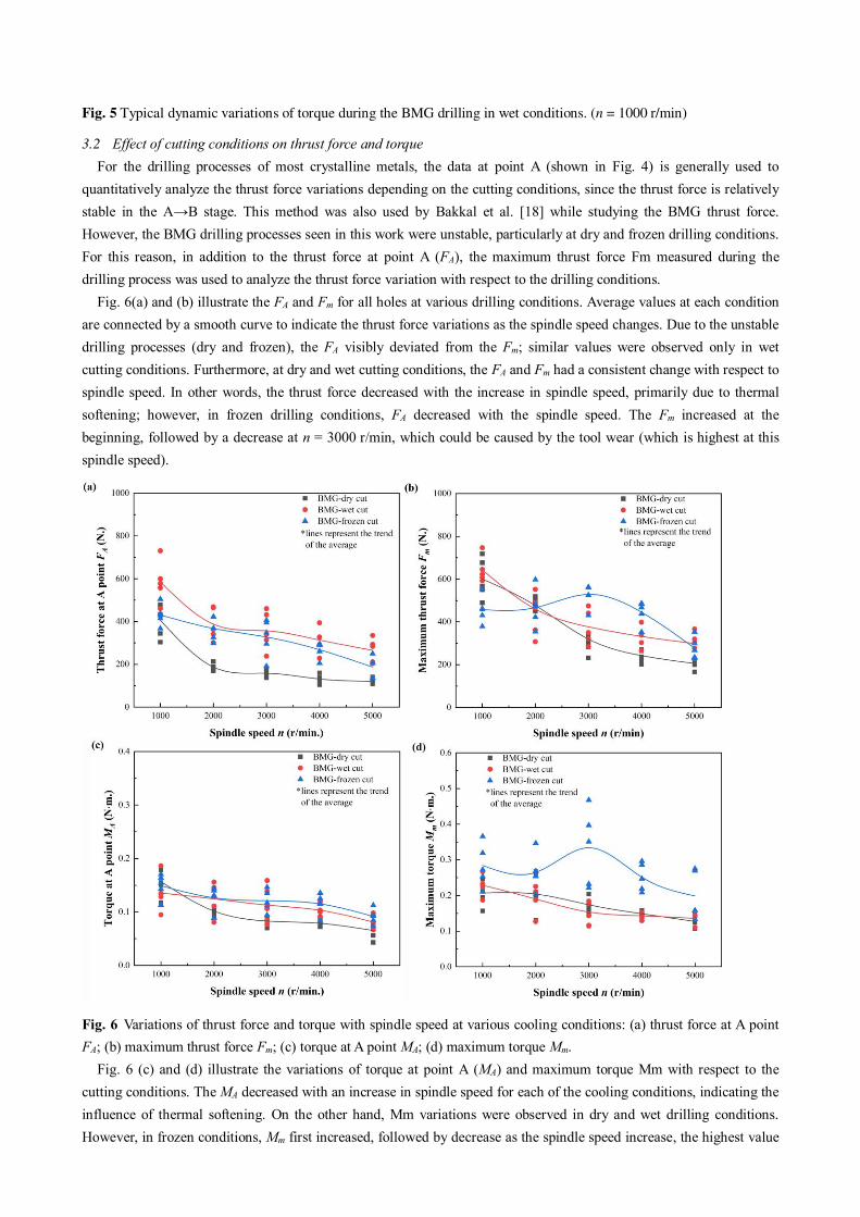
Fig. 5 Typical dynamic variations of torque during the BMG drilling in wet conditions. (n = 1000 r/min)
3.2 Effect of cutting conditions on thrust force and torque For the drilling processes of most crystalline metals, the data at point A (shown in Fig. 4) is generally used to
quantitatively analyze the thrust force variations depending on the cutting conditions, since the thrust force is relatively stable in the A→B stage. This method was also used by Bakkal et al. [18] while studying the BMG thrust force. However, the BMG drilling processes seen in this work were unstable, particularly at dry and frozen drilling conditions. For this reason, in addition to the thrust force at point A (FA), the maximum thrust force Fm measured during the drilling process was used to analyze the thrust force variation with respect to the drilling conditions.
Fig. 6(a) and (b) illustrate the FA and Fm for all holes at various drilling conditions. Average values at each condition are connected by a smooth curve to indicate the thrust force variations as the spindle speed changes. Due to the unstable drilling processes (dry and frozen), the FA visibly deviated from the Fm; similar values were observed only in wet cutting conditions. Furthermore, at dry and wet cutting conditions, the FA and Fm had a consistent change with respect to spindle speed. In other words, the thrust force decreased with the increase in spindle speed, primarily due to thermal softening; however, in frozen drilling conditions, FA decreased with the spindle speed. The Fm increased at the beginning, followed by a decrease at n = 3000 r/min, which could be caused by the tool wear (which is highest at this spindle speed).
Fig. 6 Variations of thrust force and torque with spindle speed at various cooling conditions: (a) thrust force at A point FA; (b) maximum thrust force Fm; (c) torque at A point MA; (d) maximum torque Mm.
Fig. 6 (c) and (d) illustrate the variations of torque at point A (MA) and maximum torque Mm with respect to the cutting conditions. The MA decreased with an increase in spindle speed for each of the cooling conditions, indicating the influence of thermal softening. On the other hand, Mm variations were observed in dry and wet drilling conditions. However, in frozen conditions, Mm first increased, followed by decrease as the spindle speed increase, the highest value
was measured at n = 3000 r/min, indicating the relationship to the most severe tool wear (will be discussed in section four). Furthermore, it should be noted that the frozen drilling resulted in higher MA and Mm values compared to other conditions. Considering that, the low temperature (-8.5ºC) might have no significant effect on the BMG strengh. The literature indicated that the Vit1 BMG compressive strength increased by 17% when the ambient temperature was reduced from room temperature to -175 ºC [23]. Thus, the authors concluded that the higher torque in frozen drilling was mainly caused by the combined effect of increased tool wear and weakened thermal softening.
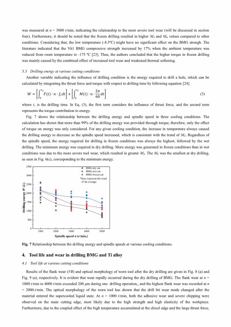
3.3 Drilling energy at various cutting conditions Another variable indicating the influence of drilling condition is the energy required to drill a hole, which can be
calculated by integrating the thrust force and torque with respect to drilling time by following equation [24]. 𝑊 = [∫ 𝐹(𝑡) ∙ 𝑛 ∙ 𝑓𝑟𝑑𝑡𝑡𝑐0 ] + [∫ 𝑀(𝑡) ∙ 𝑛 ∙ 2𝜋60 𝑑𝑡𝑡𝑐
0 ] (3)
where tc is the drilling time. In Eq. (3), the first term considers the influence of thrust force, and the second term represents the torque contribution to energy.
Fig. 7 shows the relationship between the drilling energy and spindle speed in three cooling conditions. The calculation has shown that more than 99% of the drilling energy was provided through torque, therefore, only the effect of torque on energy was only considered. For any given cooling condition, the increase in temperature always caused the drilling energy to decrease as the spindle speed increased, which is consistent with the trend of MA. Regardless of the spindle speed, the energy required for drilling in frozen conditions was always the highest, followed by the wet drilling. The minimum energy was required in dry drilling. More energy was generated in frozen conditions than in wet conditions was due to the more severe tool wear, which resulted in greater MA. The MA was the smallest at dry drilling, as seen in Fig. 6(c), corresponding to the minimum energy.
Fig. 7 Relationship between the drilling energy and spindle speeds at various cooling conditions.
4. Tool life and wear in drilling BMG and Ti alloy
4.1 Tool life at various cutting conditions
Results of the flank wear (VB) and optical morphology of worn tool after the dry drilling are given in Fig. 8 (a) and Fig. 9 (a), respectively. It is evident that wear rapidly occurred during the dry drilling of BMG. The flank wear at n = 1000 r/min to 4000 r/min exceeded 200 μm during one drilling operation,, and the highest flank wear was recorded at n = 2000 r/min. The optical morphology of the worn tool has shown that the drill bit wear mode changed after the material entered the supercooled liquid state. At n = 1000 r/min, both the adhesive wear and severe chipping were observed on the main cutting edge, most likely due to the high strength and high elasticity of the workpiece. Furthermore, due to the coupled effect of the high temperature accumulated at the chisel edge and the large thrust force,

the drill bit was subjected to severe plastic deformation and was flattened. When BMG initially entered the supercooled liquid state at n = 2000 r/min, the material strength and elasticity decreased. The abrasive wear of the drill bit flank face increased due to faster friction, however, no obvious chipping occurred. The supercooled liquid material maintained a high strength, meaning that the chisel edge was also plastically deformed by the thermomechanical coupling effect. However the deformation degree was lower compared to the previous case (n = 1000 r/min). As the spindle speed was gradually increased from 2000 r/min to 5000 r/min, the strength of the supercooled liquid material rapidly decreased as the cutting temperature increased that resulted in a rapid decline in thrust force, which in turn reduced the flank wear. The thermomechanical coupling effect at the chisel edge transformed into a single thermal effect, the drill tip maintained the complete shape due to the lack of force needed to deform it.
During the wet drilling conditions (Fig. 8(b)), after drilling nine holes, the flank wear at all spindle speeds did not exceed 200 μm. The maximum flank wear occurred at n = 2000 r/min, while the minimum value was measured at n = 4000 r/min and 5000 r/min. The later were similar to those seen in dry drilling. However, compared to dry drilling, the lubrication provided by the cutting fluid reduced the flank wear by 38.7% at n = 2000 r/min, by 43% at n = 4000 r/min and by 27 % at n = 5000 r/min). Additionally, higher spindle speed tended to decrease the flank wear, indicating that the appropriate increase in the spindle speed (which corresponds to the higher cutting temperature) softens the workpiece during wet cutting BMG, thereby extending the tool life. Based on the results of the worn tool optical morphology (Fig. 9(b)), it can be concluded that the wear mode during wet drilling was the same as that of the dry drilling at n = 1000 r/min. Also, the high material strength and elasticity caused abrasive wear and edge chipping in there cooling conditions.
In the frozen drilling conditions (Fig. 8(c)), it was expected that the freezing would improve the tool life to a certain extent; however, the improvement was more conservative compared to cutting fluid. After the drilling was finished, the flank wear exceeded 200 μm only at n = 3000 r/min. Furthermore, the worn tool optical morphology (Fig.9 (c)) has shown that, in addition to abrasion and chipping, a large area of white or light-yellow adhesions on the main cutting edge flank face (in specimens machined at n = 1000 r/min…4000 r/min). The adhesive wear was generally affected by the contact pressure, temperature and sliding speed. The increase in adhesive wear during the frozen drilling was most likely caused by the larger thrust force (i.e. the contact pressure between the workpiece and main cutting edge), compared to other cooling conditions. When frozen drilling the holes No. 5 to 9 at n = 5000 r/min, the material was in the supercooled liquid state; therefore, the drill bit wear morphology was identical to that found in dry cutting at the same speed.
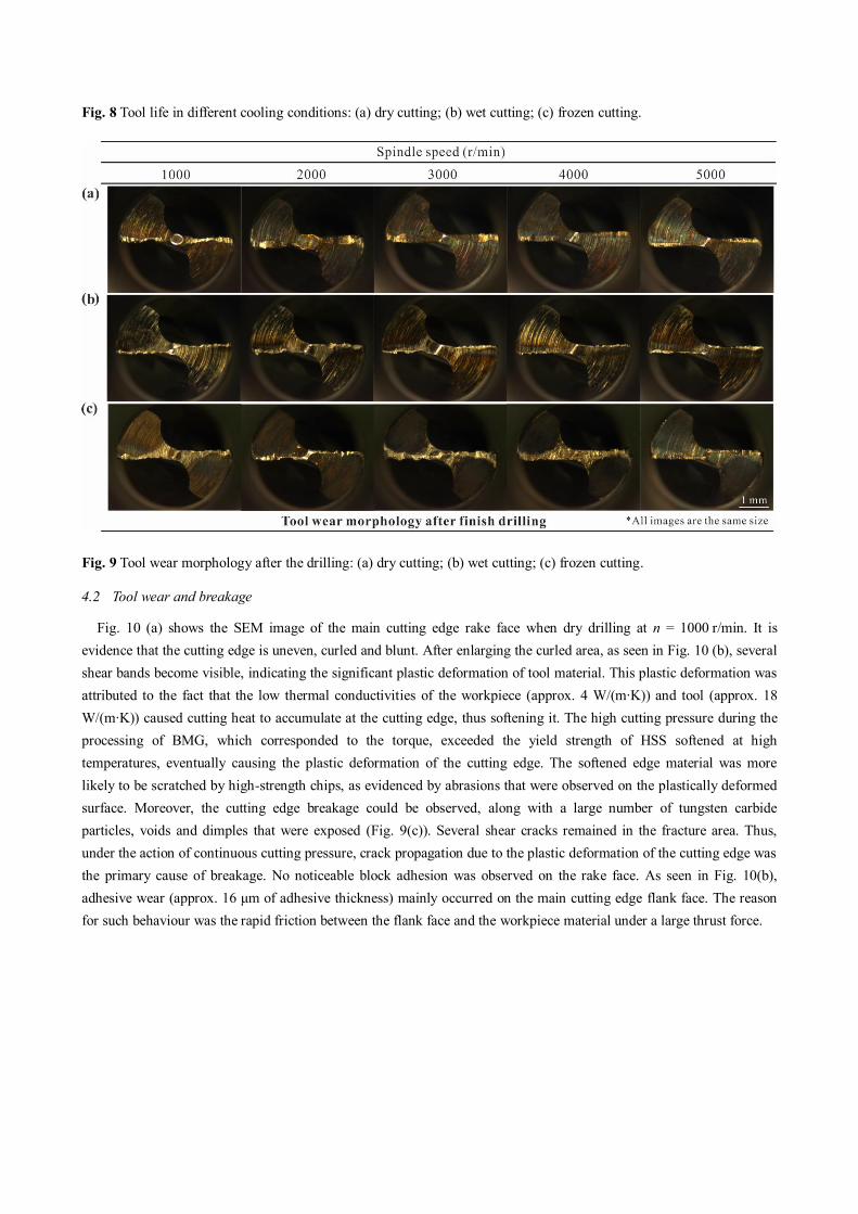
Fig. 8 Tool life in different cooling conditions: (a) dry cutting; (b) wet cutting; (c) frozen cutting.
Fig. 9 Tool wear morphology after the drilling: (a) dry cutting; (b) wet cutting; (c) frozen cutting.
4.2 Tool wear and breakage
Fig. 10 (a) shows the SEM image of the main cutting edge rake face when dry drilling at n = 1000 r/min. It is evidence that the cutting edge is uneven, curled and blunt. After enlarging the curled area, as seen in Fig. 10 (b), several shear bands become visible, indicating the significant plastic deformation of tool material. This plastic deformation was attributed to the fact that the low thermal conductivities of the workpiece (approx. 4 W/(m∙K)) and tool (approx. 18 W/(m∙K)) caused cutting heat to accumulate at the cutting edge, thus softening it. The high cutting pressure during the processing of BMG, which corresponded to the torque, exceeded the yield strength of HSS softened at high temperatures, eventually causing the plastic deformation of the cutting edge. The softened edge material was more likely to be scratched by high-strength chips, as evidenced by abrasions that were observed on the plastically deformed surface. Moreover, the cutting edge breakage could be observed, along with a large number of tungsten carbide particles, voids and dimples that were exposed (Fig. 9(c)). Several shear cracks remained in the fracture area. Thus, under the action of continuous cutting pressure, crack propagation due to the plastic deformation of the cutting edge was the primary cause of breakage. No noticeable block adhesion was observed on the rake face. As seen in Fig. 10(b), adhesive wear (approx. 16 μm of adhesive thickness) mainly occurred on the main cutting edge flank face. The reason for such behaviour was the rapid friction between the flank face and the workpiece material under a large thrust force.
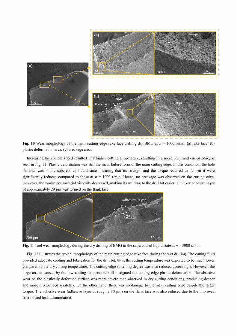
Fig. 10 Wear morphology of the main cutting edge rake face drilling dry BMG at n = 1000 r/min: (a) rake face; (b) plastic deformation area; (c) breakage area.
Increasing the spindle speed resulted in a higher cutting temperature, resulting in a more blunt and curled edge, as seen in Fig. 11. Plastic deformation was still the main failure form of the main cutting edge. In this condition, the hole material was in the supercooled liquid state, meaning that its strength and the torque required to deform it were significantly reduced compared to those at n = 1000 r/min. Hence, no breakage was observed on the cutting edge. However, the workpiece material viscosity decreased, making its welding to the drill bit easier; a thicker adhesive layer of approximately 29 μm was formed on the flank face.
Fig. 11 Tool wear morphology during the dry drilling of BMG in the supercooled liquid state at n = 3000 r/min.
Fig. 12 illustrates the typical morphology of the main cutting edge rake face during the wet drilling. The cutting fluid provided adequate cooling and lubrication for the drill bit; thus, the cutting temperature was expected to be much lower compared to the dry cutting temperature. The cutting edge softening degree was also reduced accordingly. However, the large torque caused by the low cutting temperature still instigated the cutting edge plastic deformation. The abrasive wear on the plastically deformed surface was more severe than observed in dry cutting conditions, producing deeper and more pronounced scratches. On the other hand, there was no damage to the main cutting edge despite the larger torque. The adhesive wear (adhesive layer of roughly 10 μm) on the flank face was also reduced due to the improved friction and heat accumulation.
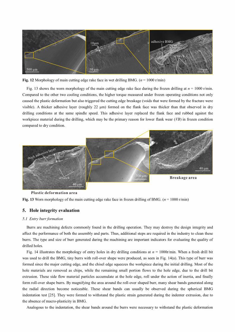
Fig. 12 Morphology of main cutting edge rake face in wet drilling BMG. (n = 1000 r/min)
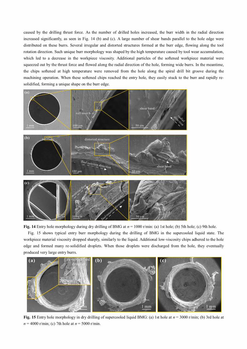
Fig. 13 shows the worn morphology of the main cutting edge rake face during the frozen drilling at n = 1000 r/min. Compared to the other two cooling conditions, the higher torque measured under frozen operating conditions not only caused the plastic deformation but also triggered the cutting edge breakage (voids that were formed by the fracture were visible). A thicker adhesive layer (roughly 22 μm) formed on the flank face was thicker than that observed in dry drilling conditions at the same spindle speed. This adhesive layer replaced the flank face and rubbed against the workpiece material during the drilling, which may be the primary reason for lower flank wear (VB) in frozen condition compared to dry condition.
Fig. 13 Worn morphology of the main cutting edge rake face in frozen drilling of BMG. (n = 1000 r/min)
5. Hole integrity evaluation 5.1 Entry burr formation
Burrs are machining defects commonly found in the drilling operation. They may destroy the design integrity and affect the performance of both the assembly and parts. Thus, additional steps are required in the industry to clean these burrs. The type and size of burr generated during the machining are important indicators for evaluating the quality of drilled holes.
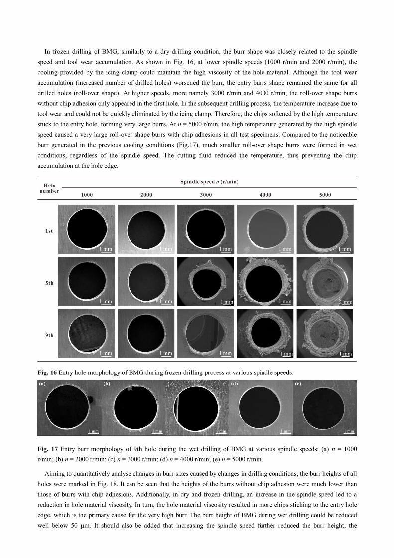
Fig. 14 illustrates the morphology of entry holes in dry drilling conditions at n = 1000r/min. When a fresh drill bit was used to drill the BMG, tiny burrs with roll-over shape were produced, as seen in Fig. 14(a). This type of burr was formed since the major cutting edge, and the chisel edge squeezes the workpiece during the initial drilling. Most of the hole materials are removed as chips, while the remaining small portion flows to the hole edge, due to the drill bit extrusion. These side flow material particles accumulate at the hole edge, roll under the action of inertia, and finally form roll-over shape burrs. By magnifying the area around the roll-over shaped burr, many shear bands generated along the radial direction become noticeable. These shear bands can usually be observed during the spherical BMG indentation test [25]. They were formed to withstand the plastic strain generated during the indenter extrusion, due to the absence of macro-plasticity in BMG.
Analogous to the indentation, the shear bands around the burrs were necessary to withstand the plastic deformation
caused by the drilling thrust force. As the number of drilled holes increased, the burr width in the radial direction increased significantly, as seen in Fig. 14 (b) and (c). A large number of shear bands parallel to the hole edge were distributed on these burrs. Several irregular and distorted structures formed at the burr edge, flowing along the tool rotation direction. Such unique burr morphology was shaped by the high temperature caused by tool wear accumulation, which led to a decrease in the workpiece viscosity. Additional particles of the softened workpiece material were squeezed out by the thrust force and flowed along the radial direction of the hole, forming wide burrs. In the meantime, the chips softened at high temperature were removed from the hole along the spiral drill bit groove during the machining operation. When these softened chips reached the entry hole, they easily stuck to the burr and rapidly re-
solidified, forming a unique shape on the burr edge.
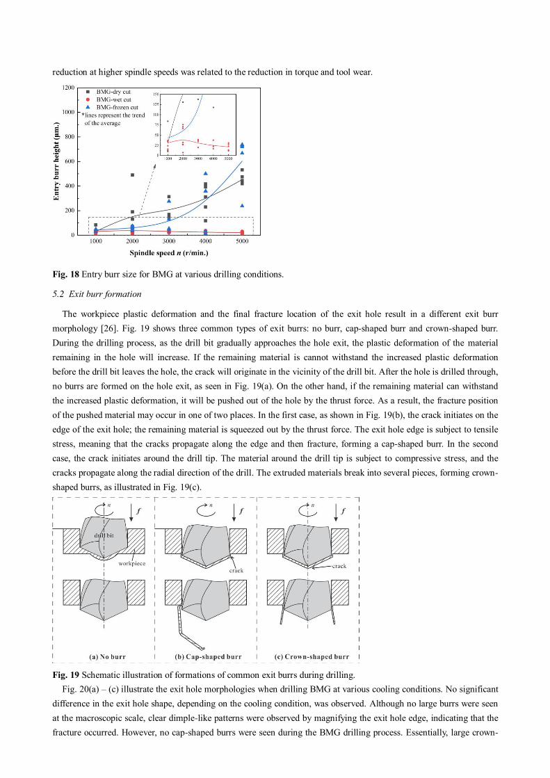
Fig. 14 Entry hole morphology during dry drilling of BMG at n = 1000 r/min: (a) 1st hole; (b) 5th hole; (c) 9th hole. Fig. 15 shows typical entry burr morphology during the drilling of BMG in the supercooled liquid state. The
workpiece material viscosity dropped sharply, similarly to the liquid. Additional low-viscosity chips adhered to the hole edge and formed many re-solidified droplets. When those droplets were discharged from the hole, they eventually produced very large entry burrs.
Fig. 15 Entry hole morphology in dry drilling of supercooled liquid BMG: (a) 1st hole at n = 3000 r/min; (b) 3rd hole at n = 4000 r/min; (c) 7th hole at n = 5000 r/min.
In frozen drilling of BMG, similarly to a dry drilling condition, the burr shape was closely related to the spindle speed and tool wear accumulation. As shown in Fig. 16, at lower spindle speeds (1000 r/min and 2000 r/min), the cooling provided by the icing clamp could maintain the high viscosity of the hole material. Although the tool wear accumulation (increased number of drilled holes) worsened the burr, the entry burrs shape remained the same for all drilled holes (roll-over shape). At higher speeds, more namely 3000 r/min and 4000 r/min, the roll-over shape burrs without chip adhesion only appeared in the first hole. In the subsequent drilling process, the temperature increase due to tool wear and could not be quickly eliminated by the icing clamp. Therefore, the chips softened by the high temperature stuck to the entry hole, forming very large burrs. At n = 5000 r/min, the high temperature generated by the high spindle speed caused a very large roll-over shape burrs with chip adhesions in all test specimens. Compared to the noticeable burr generated in the previous cooling conditions (Fig.17), much smaller roll-over shape burrs were formed in wet conditions, regardless of the spindle speed. The cutting fluid reduced the temperature, thus preventing the chip accumulation at the hole edge.
Fig. 16 Entry hole morphology of BMG during frozen drilling process at various spindle speeds.
Fig. 17 Entry burr morphology of 9th hole during the wet drilling of BMG at various spindle speeds: (a) n = 1000 r/min; (b) n = 2000 r/min; (c) n = 3000 r/min; (d) n = 4000 r/min; (e) n = 5000 r/min.
Aiming to quantitatively analyse changes in burr sizes caused by changes in drilling conditions, the burr heights of all holes were marked in Fig. 18. It can be seen that the heights of the burrs without chip adhesion were much lower than those of burrs with chip adhesions. Additionally, in dry and frozen drilling, an increase in the spindle speed led to a reduction in hole material viscosity. In turn, the hole material viscosity resulted in more chips sticking to the entry hole edge, which is the primary cause for the very high burr. The burr height of BMG during wet drilling could be reduced well below 50 μm. It should also be added that increasing the spindle speed further reduced the burr height; the
reduction at higher spindle speeds was related to the reduction in torque and tool wear.
Fig. 18 Entry burr size for BMG at various drilling conditions.
5.2 Exit burr formation
The workpiece plastic deformation and the final fracture location of the exit hole result in a different exit burr morphology [26]. Fig. 19 shows three common types of exit burrs: no burr, cap-shaped burr and crown-shaped burr. During the drilling process, as the drill bit gradually approaches the hole exit, the plastic deformation of the material remaining in the hole will increase. If the remaining material is cannot withstand the increased plastic deformation before the drill bit leaves the hole, the crack will originate in the vicinity of the drill bit. After the hole is drilled through, no burrs are formed on the hole exit, as seen in Fig. 19(a). On the other hand, if the remaining material can withstand the increased plastic deformation, it will be pushed out of the hole by the thrust force. As a result, the fracture position of the pushed material may occur in one of two places. In the first case, as shown in Fig. 19(b), the crack initiates on the edge of the exit hole; the remaining material is squeezed out by the thrust force. The exit hole edge is subject to tensile stress, meaning that the cracks propagate along the edge and then fracture, forming a cap-shaped burr. In the second case, the crack initiates around the drill tip. The material around the drill tip is subject to compressive stress, and the cracks propagate along the radial direction of the drill. The extruded materials break into several pieces, forming crown-
shaped burrs, as illustrated in Fig. 19(c).
Fig. 19 Schematic illustration of formations of common exit burrs during drilling. Fig. 20(a) – (c) illustrate the exit hole morphologies when drilling BMG at various cooling conditions. No significant
difference in the exit hole shape, depending on the cooling condition, was observed. Although no large burrs were seen at the macroscopic scale, clear dimple-like patterns were observed by magnifying the exit hole edge, indicating that the fracture occurred. However, no cap-shaped burrs were seen during the BMG drilling process. Essentially, large crown-
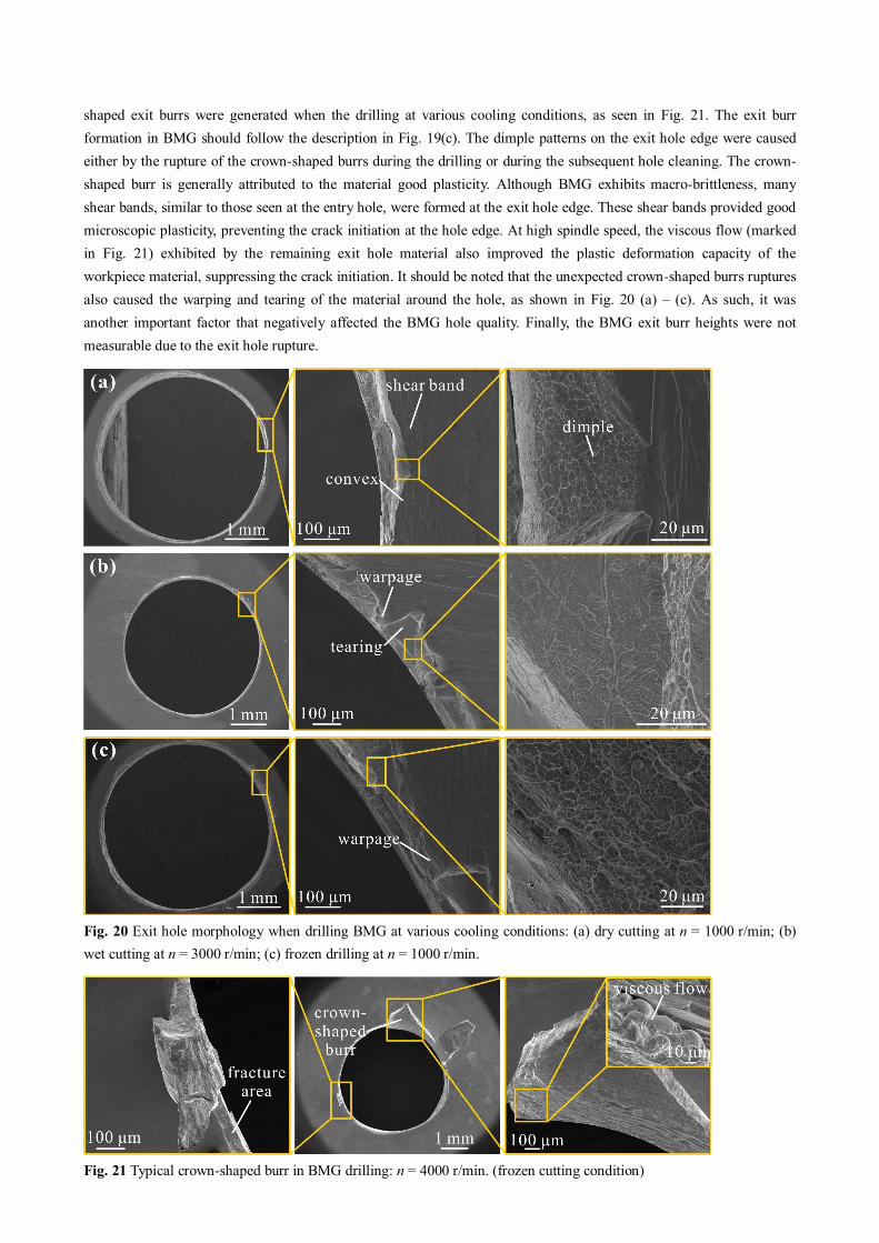
shaped exit burrs were generated when the drilling at various cooling conditions, as seen in Fig. 21. The exit burr formation in BMG should follow the description in Fig. 19(c). The dimple patterns on the exit hole edge were caused either by the rupture of the crown-shaped burrs during the drilling or during the subsequent hole cleaning. The crown-
shaped burr is generally attributed to the material good plasticity. Although BMG exhibits macro-brittleness, many shear bands, similar to those seen at the entry hole, were formed at the exit hole edge. These shear bands provided good microscopic plasticity, preventing the crack initiation at the hole edge. At high spindle speed, the viscous flow (marked in Fig. 21) exhibited by the remaining exit hole material also improved the plastic deformation capacity of the workpiece material, suppressing the crack initiation. It should be noted that the unexpected crown-shaped burrs ruptures also caused the warping and tearing of the material around the hole, as shown in Fig. 20 (a) – (c). As such, it was another important factor that negatively affected the BMG hole quality. Finally, the BMG exit burr heights were not measurable due to the exit hole rupture.
Fig. 20 Exit hole morphology when drilling BMG at various cooling conditions: (a) dry cutting at n = 1000 r/min; (b) wet cutting at n = 3000 r/min; (c) frozen drilling at n = 1000 r/min.
Fig. 21 Typical crown-shaped burr in BMG drilling: n = 4000 r/min. (frozen cutting condition)

5.3 Hole accuracy
Diameter deviation is an important indicator for evaluating the hole drilling quality in the industry. Generally, the factors affecting the hole diameter accuracy include: drill wander, thermal expansion and elastic recovery of the hole material. Both the drill wander and thermal expansion will enlarge the hole diameter, while the elastic recovery may decrease the hole diameter. Drill wander was usually caused by the deviation of the machine tool spindle and the drill bit vibration. It can also be triggered by the asymmetric thrust force and torque on the two cutting edges, which is generally caused by the uneven wear of the main cutting edge. The heat generated during the drilling is dissipated once the machining is completed, meaning that the hole material will shrink dependent on thermal expansion, causing the diameter to increase. On the other hand, the hole wall will undergo elastoplastic deformation once it is loaded by the thrust force. After completing the processing, the hole material elastic recovery causes a reduction in the hole diameter.
The diameter of all the holes is shown in Fig. 22 (a). Most entry holes were oversized, indicating that the drill wander and thermal expansion are the dominant factors affecting the BMG entry hole diameter. At a constant spindle speed, wet drilling specimens displayed lower entry hole diameter deviation compared to other cooling conditions, primarily due to the less prominent tool wear, lower temperature, and smaller burrs. The smallest deviations were obtained for wet drilling at n = 4000 r/min; only one hole exceeded the medium level, while the others were kept within the fine level. Furthermore, due to the absence of sufficient cooling at dry and frozen cutting conditions, most of the entry holes were out of medium range. The diameter deviation further increased with the increase in spindle speed. High temperature and the very large roll-over shape burrs with chip adhesion were the main causes for the increase in hole diameter.
Additionally, due to the drill wander and the thermal expansion, the exit hole diameters were smaller than those of the entry holes, which resulted in the tapered drilled holes. Fig. 22 (b) illustrates the taper of each hole under various cutting conditions. Wet drilling resulted in the lowest taper angle due to the adequate cooling effect; taper angles were insensitive to spindle speed at this cooling condition. The taper angle ranged between 2.2 º and 2.55 º. On the other hand, the taper angle in the frozen drilling process increased significantly as the spindle speed increased. The reason for such behavior is the distance between the entry hole and the icing clamp, resulting in slow heat dissipation. The exit hole was close to the icing clamping and thus had a fast temperature drop. As a result, the thermal expansion and contraction of the entry and exit holes were asymmetric, leading to a large taper. In dry drilling conditions, the average taper angle at n = 1000 r/min was 2.57º. Although several holes could be drilled through in dry conditions at higher spindle speeds, the hole shape was severely distorted, resulting in very large taper.
The circularities Hc of entry and exit holes at various cutting conditions were shown in Fig. 22(c). The exit hole circularity was usually higher compared to the entry hole, possibly due to the damping of the low-frequency tool vibration as the tool progressed deeper into the hole. For a given spindle speed, the use of cutting fluid resulted in the highest hole circularity. For the wet drilling process, the hole circularity was between 0.987 and 0.993 for the entry and 0.989 to 0.992 for the exit hole; the values increased with the spindle speed. This could be explained by the greater rotational stability of the drill bit at higher speeds. However, this rule did not hold when considering the frozen operation conditions, where the hole circularities for both the entry and exit were lowest at n = 3000 r/min. This was mostly due to the most serious tool wear, the highest torque, and the highest thrust force, all of which increased the plastic deformation of the workpiece.
In practical manufacturing, cutting fluid is still the preferred cooling method when drilling BMGs. Due to a beneficial combination of cooling and lubrication effects, it results in higher tool life, effectively suppresses the entry burrs and improves the hole accuracy (compared to dry and frozen drilling methods). Additionally, the use of higher cutting speeds (i.e. 4000 r/min and 5000 r/min), can increase the material removal rate and while also improving both the tool life and hole accuracy.
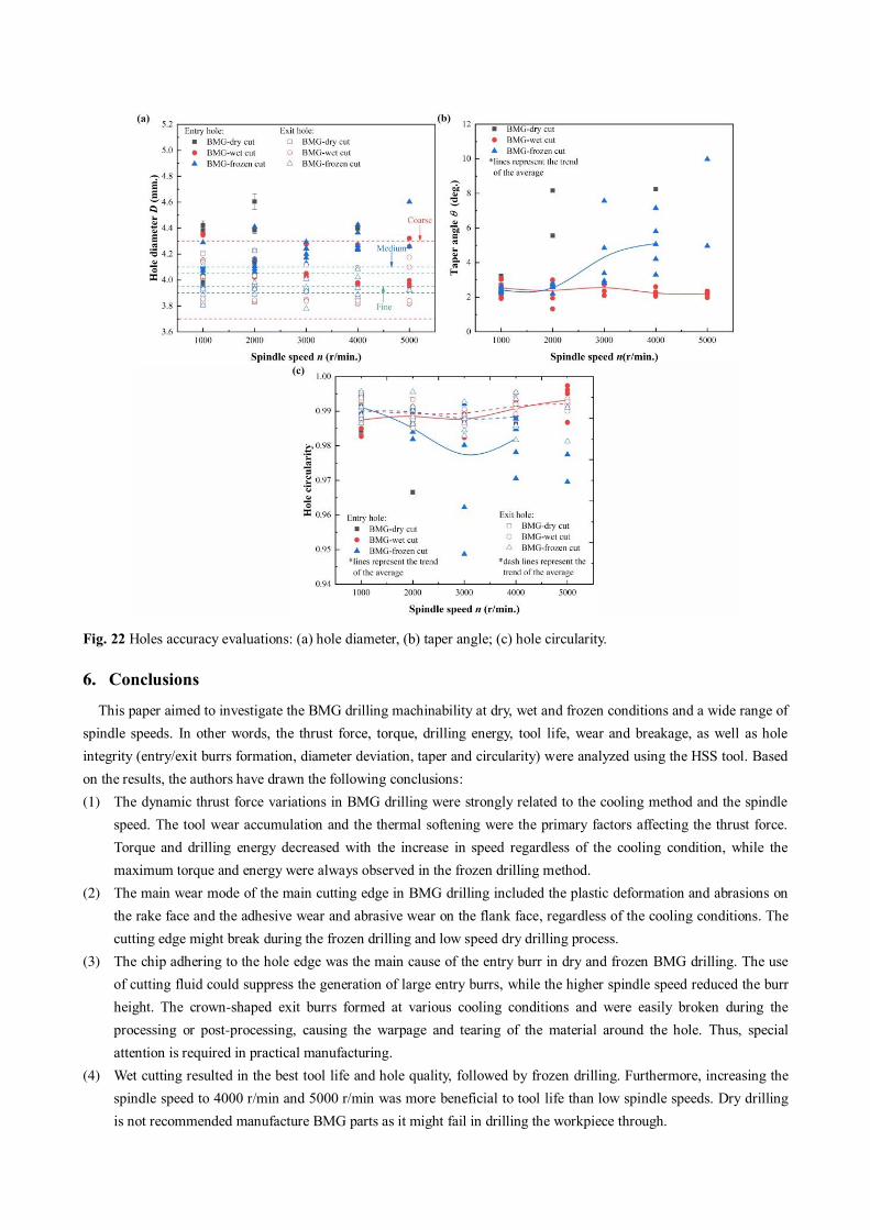
Fig. 22 Holes accuracy evaluations: (a) hole diameter, (b) taper angle; (c) hole circularity.
6. Conclusions
This paper aimed to investigate the BMG drilling machinability at dry, wet and frozen conditions and a wide range of spindle speeds. In other words, the thrust force, torque, drilling energy, tool life, wear and breakage, as well as hole integrity (entry/exit burrs formation, diameter deviation, taper and circularity) were analyzed using the HSS tool. Based on the results, the authors have drawn the following conclusions: (1) The dynamic thrust force variations in BMG drilling were strongly related to the cooling method and the spindle
speed. The tool wear accumulation and the thermal softening were the primary factors affecting the thrust force. Torque and drilling energy decreased with the increase in speed regardless of the cooling condition, while the maximum torque and energy were always observed in the frozen drilling method.
(2) The main wear mode of the main cutting edge in BMG drilling included the plastic deformation and abrasions on the rake face and the adhesive wear and abrasive wear on the flank face, regardless of the cooling conditions. The cutting edge might break during the frozen drilling and low speed dry drilling process.
(3) The chip adhering to the hole edge was the main cause of the entry burr in dry and frozen BMG drilling. The use of cutting fluid could suppress the generation of large entry burrs, while the higher spindle speed reduced the burr height. The crown-shaped exit burrs formed at various cooling conditions and were easily broken during the processing or post-processing, causing the warpage and tearing of the material around the hole. Thus, special attention is required in practical manufacturing.
(4) Wet cutting resulted in the best tool life and hole quality, followed by frozen drilling. Furthermore, increasing the spindle speed to 4000 r/min and 5000 r/min was more beneficial to tool life than low spindle speeds. Dry drilling is not recommended manufacture BMG parts as it might fail in drilling the workpiece through.
Author contribution Zhiyu Hu carried out experiments and drafted the manuscript. Chengyong Wang provide the manuscript revise suggestion. Feng Ding drafted the manuscript. Tao Zhang prepared materials. Lijuan Zheng and Xuguang Zhu provided suggestions. All authors read and approved the final manuscript.
Funding This work received financial support from the Key program of the National Natural Science Foundation of China (Grant No.51735003). The authors also wish to express their special thanks for the support from the Key Basic and Applied Research Program of Guangdong Province, China (Grant No. 2019B030302010).
Availability of data and material Not applicable.
Code availability Not applicable.
Declarations
Ethics approval The work was original research that has not been published previously, and not under consideration for publication elsewhere, in whole or in part.
Consent to participate The authors all approved to participate.
Consent for publication It is approved by all authors for publication.
Conflict of interest The authors declare no competing interests.
Reference 1. Telford M (2004) The case for bulk metallic glass. Mater Today 7(3):36-43. https://doi.org/10.1016/S1369-
7021(04)00124-5
2. Byrne CJ, Eldrup M (2008) Materials science: bulk metallic glasses. Science 321:502–503
https://doi.org/10.1126/science.1158864
3. LI HF, ZHENG YF (2016) Recent advances in bulk metallic glasses for biomedical applications. Acta Biomater
36:1–20. https://doi.org/10.1016/j.actbio.2016.03.047
4. Meagher P, O'Cearbhaill ED, Byrne JH, Browne DJ (2016) Bulk metallic glasses for implantable medical devices
and surgical tools. Adv Mater 28(27):5755–5762. https://doi.org/10.1002/adma.201505347
5. Khan MM, Nemati A, Rahman ZU, Shah U, Asgar H, Haider W, (2017) Recent advancements in bulk metallic
glasses and their applications: a review. Crit Rev Solid State 1–36. https://doi.org/10.1080/10408436.2017.1358149
6. Liu, LH, Zhang T, Liu ZY, Yu CY. Dong XX, He LJ, Gao K, Zhu X.G, Li WH., Wang CY, Li PJ, Zhang LC, Li L
(2018) Near-net forming complex shaped Zr-based bulk metallic glasses by high pressure die casting. Materials
11:2338. https:// doi.org/10.3390/ma11112338
7. Liu LH, Zhang T, Liu, ZY, Wang CY, He LJ, Li PJ, Li WR, Li L (2019) Abnormal increase of glass forming
ability under rising mold temperature in high pressure die casting. Mater Lett 247:215-218.
https://doi.org/10.1016/j.matlet.2019.03.127
8. Zhang T, Meng XN, Wang CY, Li L, Yang JD, Li WR, Li RX, Zhang Y (2019) Investigations of new bulk metallic
glass alloys fabricated using a high-pressure die-casting method based on industrial grade Zr raw material. J Alloys
Compd 792:851–859. https://doi.org/10.1016/j.jallcom.2019.03.357
9. Zhang Y, Wang CY, Zhou SB, Jiang WT, Liu ZH, Xu LL (2017) A Comparison review on orthopedic surgery
using piezosurgery and conventional tools. Procedia CIRP 65:99-104. https://doi.org/10.1016/j.procir.2017.04.024
10. Chen ZH, Wang CY, Jiang WT, Tang N, Chen B (2017) A review on surgical instruments of knee arthroscopic
debridement and total hip arthroplasty. Procedia CIRP 65:291–298. https://doi.org/10.1016/j.procir.2017.05.001
11. Zhang L, Huang H (2018) Micro machining of bulk metallic glasses: a review. Int J Adv Manuf Tech 100:637–
661. https://doi.org/10.1007/s00170-018-2726-y
12. Ding F, Wang CY, Zhang T, Zheng LJ, Zhu XG (2018) High performance cutting of Zr-based bulk metallic glass:
a review of chip formation. Procedia CIRP 77:421-424. https://doi.org/10.1016/j.procir.2018.08.294
13. Ding F, Wang CY, Zhang T, Zheng LJ, Zhu XG, Li WR, Li L (2020) Investigation on chip deformation behaviors
of Zr-based bulk metallic glass during machining. J Mater Process Tech 276:116404.
https://doi.org/10.1016/j.jmatprotec.2019.116404
14. Ding F, Wang CY, Lai ZJ, Zhang T, Zhu XG, Gao K (2020) Freezing cutting characteristics and non-crystallized
processing technology of Zr-based bulk metallic glass. Chinese Journal of Mechanical Engineering. 2021,
57(3):235–246. https://doi.org/10.3901/JME.2021.03.235
15. Williams E, Lavery N (2017) Laser processing of bulk metallic glass: A review. J Mater Process Tech 247: 73–91.
http://dx.doi.org/10.1016/j.jmatprotec.2017.03.034
16. Hsieh SF, Chen L, Lin MH, Ou S F, Lin WT, Huang MS (2013) Crystallization and carbonization of an electrical
discharge machined Zr-based bulk metallic glass alloy. J Mater Res 28(22):3177–3184.
http://dx.doi.org/10.1557/jmr.2013.329
17. Bakkal M, Shih AJ, Mcspadden SB, Liu CT, Scattergood RO (2005) Light emission, chip morphology, and burr
formation in drilling the bulk metallic glass. Int J Mach Tool Manu 45(7–8):741–752.
https://doi.org/10.1016/j.ijmachtools.2004.11.004
18. Bakkal M, Shih AJ, Mcspadden SB, Scattergood RO (2005) Thrust force, torque, and tool wear in drilling the bulk
metallic glass. Int J Mach Tool Manu 45(7-8):863–872. https://doi.org/10.1016/j.ijmachtools.2004.11.005
19. Tariq NH, Muhammad G, Awais HB (2013) Effect of operating parameters on the drilling behavior of
Zr57.5Cu11.2Ni13.8Al17.5 bulk metallic glass. J Mater Res 28(23):3288–3296. https://doi.org/10.1557/jmr.2013.338
20. Zhu J, Kim HJ, Kapoor SG (2013) Microscale drilling of bulk metallic glass. ASME Journal of Micro and Nano-
Manufacturing 1(4):041004. https://doi.org/10.1115/1.4025538
21. Kuriakose S, Patowari PK, Bhatt J (2017) Machinability study of Zr-Cu-Ti metallic glass by micro hole drilling
using micro-USM. J Mater Process Tech 240:42–51. https://doi.org/10.1016/j.jmatprotec.2016.08.026
22. Lu J, Ravichandran G, Johnson WL (2003) Deformation behavior of the Zr41.2Ti13.8Cu12.5Ni10Be22.5 bulk metallic
glass over a wide range of strain-rates and temperatures. Acta Mater 51(12):3429–3443.
https://doi.org/10.1016/s1359-6454(03)00164-2
23. Tan J, Wang G, Liu ZY, Bednarcikm J, Gao YL, Zhai QJ, Mattern N, Eckert J (2014) Correlation between atomic
structure evolution and strength in a bulk metallic glass at cryogenic temperature. Sci Rep-UK 4:3879.
https://doi.org/10.1038/srep03897
24. Li R, Shih AJ (2007) High throughput drilling of titanium alloys. Chin J Mech Eng-EN 20(3):62–66.
https://doi.org/10.3901/cjme.2007.03.062
25. Patnaik MNM, Narasimhan R, Ramamurty U (2004) Spherical indentation response of metallic glasses. Acta Mater
52(11):3335–3345. https://doi.org/10.1016/j.actamat.2004.03.028
26. Zhu ZJ, Sui SC, Sun J, Li JF, Li YL (2017) Investigation on performance characteristics in drilling of Ti6Al4V
alloy. Int J Adv Manuf Tech 93(1–2):1–10. https://doi.org/10.1007/s00170-017-0508-6
Figures
Figure 1
BMG stress-strain curves at a constant strain rate of 0.01 s-1 and various temperatures (The data wasfrom ref [22].)
Figure 2
Experimental operations: (a) dry and wet drilling setup; (b) frozen drilling setup; (c) schematic of frozendrilling.
Figure 3
BMG holes drilled at various cutting conditions. Horizontal number (1–9) is the drilling sequence, verticalnumber (1–15) corresponds to the dry drilling at n = 1000 r/min to 5000 r/min (1-5), 6–10 is the wetdrilling, and 11–15 is the frozen drilling.
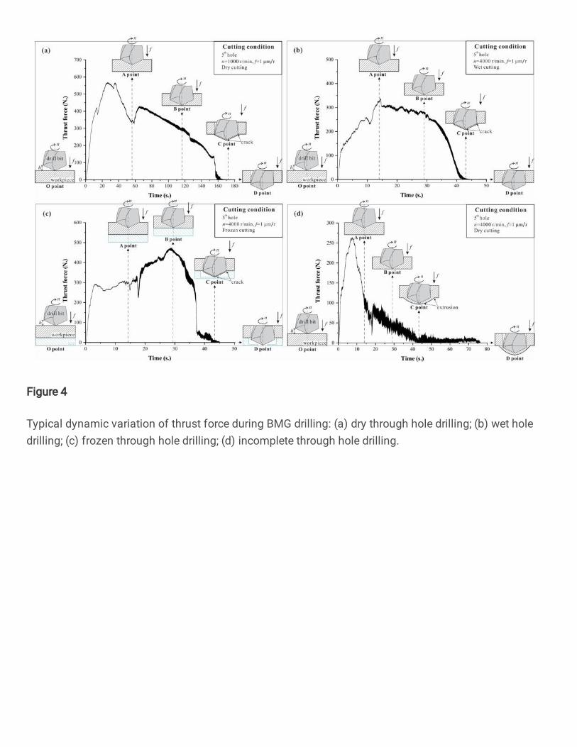
Figure 4
Typical dynamic variation of thrust force during BMG drilling: (a) dry through hole drilling; (b) wet holedrilling; (c) frozen through hole drilling; (d) incomplete through hole drilling.
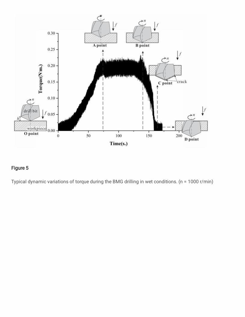
Figure 5
Typical dynamic variations of torque during the BMG drilling in wet conditions. (n = 1000 r/min)
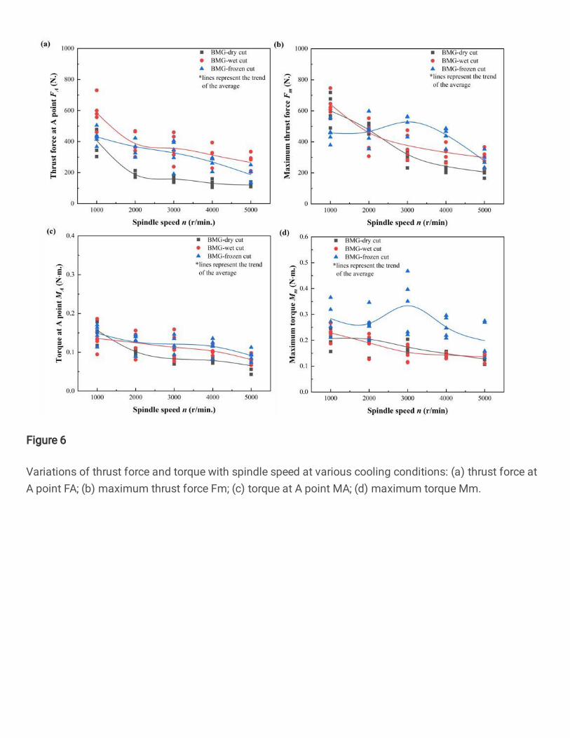
Figure 6
Variations of thrust force and torque with spindle speed at various cooling conditions: (a) thrust force atA point FA; (b) maximum thrust force Fm; (c) torque at A point MA; (d) maximum torque Mm.
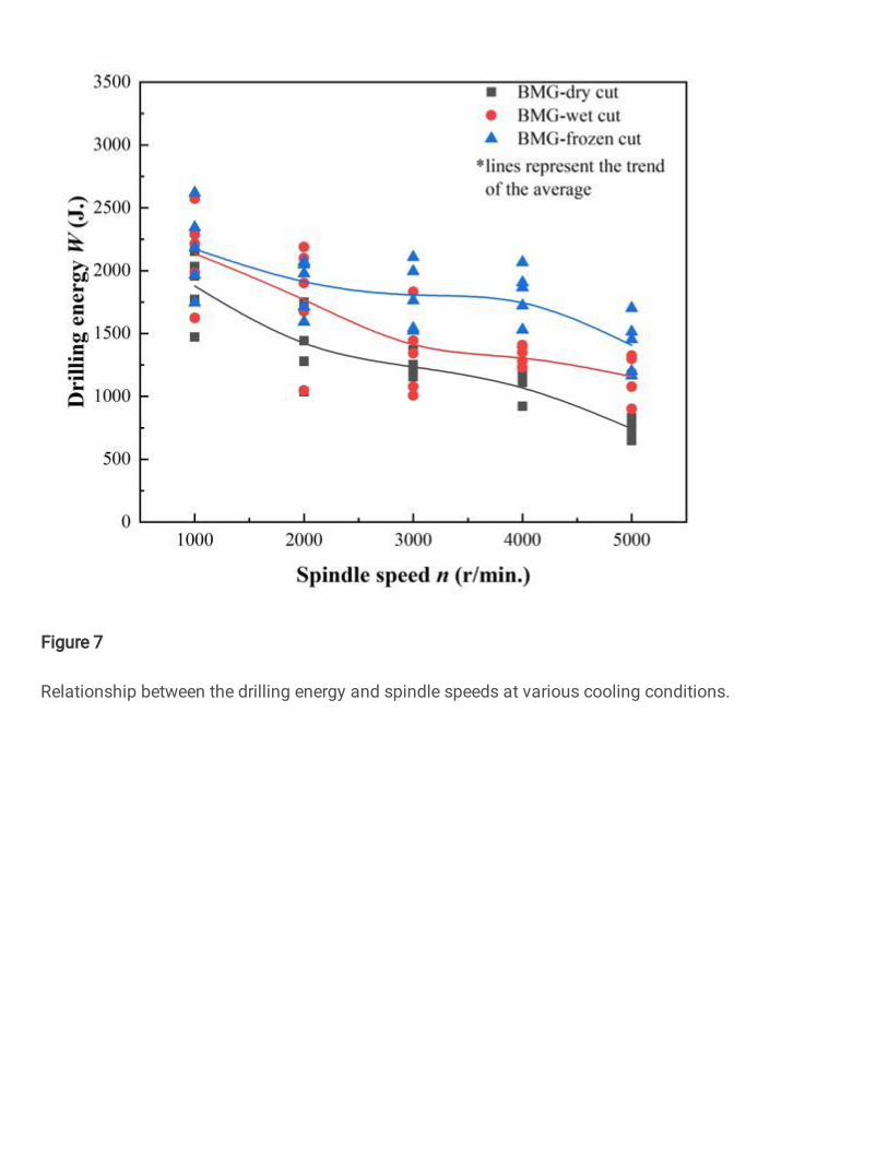
Figure 7
Relationship between the drilling energy and spindle speeds at various cooling conditions.
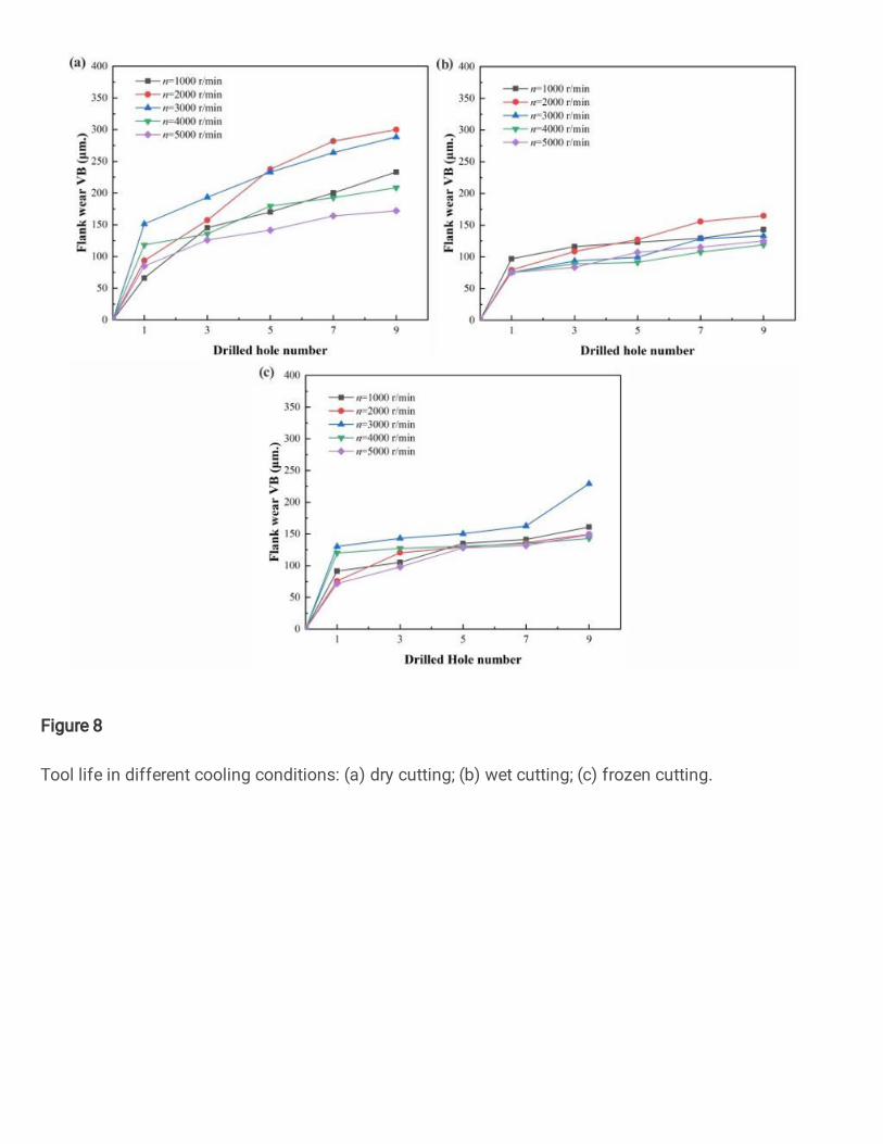
Figure 8
Tool life in different cooling conditions: (a) dry cutting; (b) wet cutting; (c) frozen cutting.
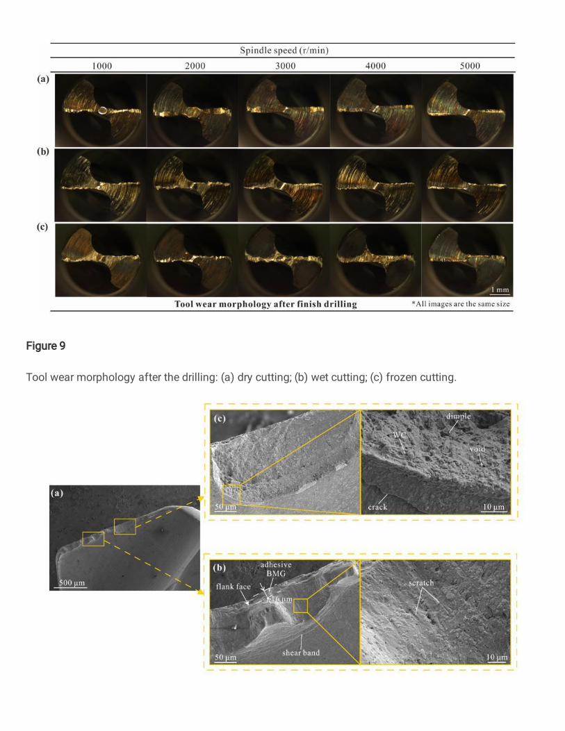
Figure 9
Tool wear morphology after the drilling: (a) dry cutting; (b) wet cutting; (c) frozen cutting.
Figure 10
Wear morphology of the main cutting edge rake face drilling dry BMG at n = 1000 r/min: (a) rake face; (b)plastic deformation area; (c) breakage area.
Figure 11
Tool wear morphology during the dry drilling of BMG in the supercooled liquid state at n = 3000 r/min.
Figure 12
Morphology of main cutting edge rake face in wet drilling BMG. (n = 1000 r/min)
Figure 13
Worn morphology of the main cutting edge rake face in frozen drilling of BMG. (n = 1000 r/min)
Figure 14
Entry hole morphology during dry drilling of BMG at n = 1000 r/min: (a) 1st hole; (b) 5th hole; (c) 9th hole.
Figure 15
Entry hole morphology in dry drilling of supercooled liquid BMG: (a) 1st hole at n = 3000 r/min; (b) 3rdhole at n = 4000 r/min; (c) 7th hole at n = 5000 r/min.
Figure 16
Entry hole morphology of BMG during frozen drilling process at various spindle speeds.
Figure 17
Entry burr morphology of 9th hole during the wet drilling of BMG at various spindle speeds: (a) n = 1000r/min; (b) n = 2000 r/min; (c) n = 3000 r/min; (d) n = 4000 r/min; (e) n = 5000 r/min.
Figure 18
Entry burr size for BMG at various drilling conditions.
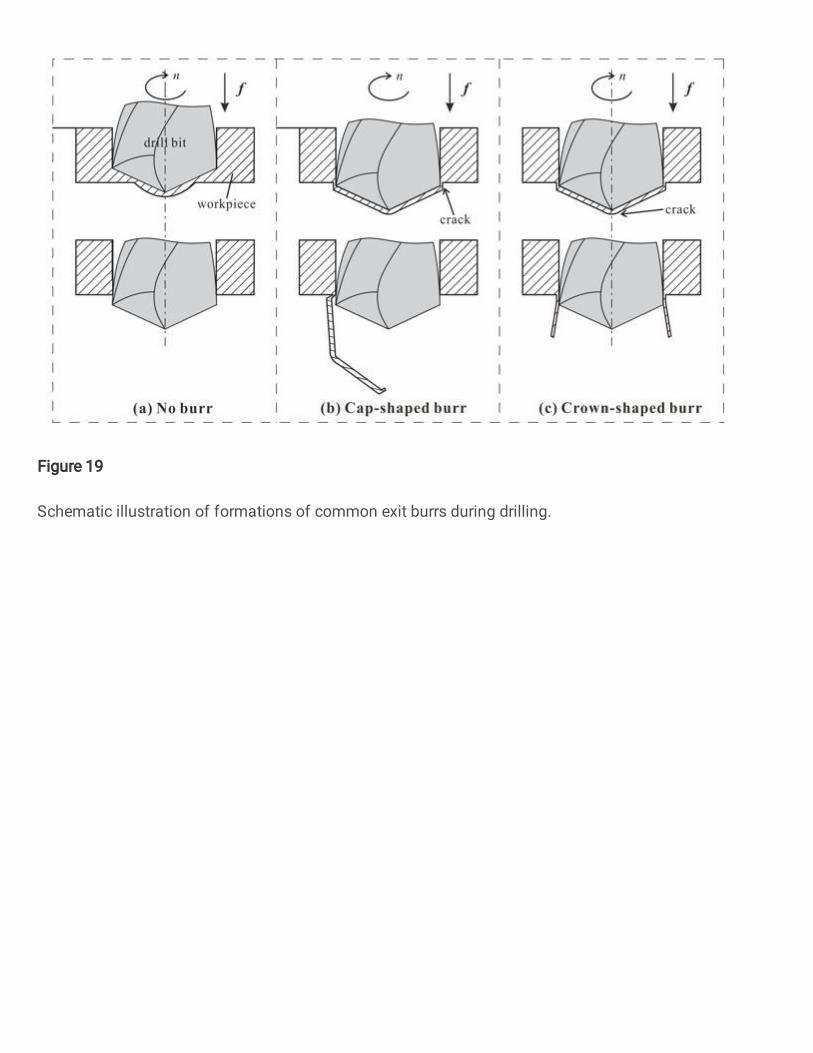
Figure 19
Schematic illustration of formations of common exit burrs during drilling.

Figure 20
Exit hole morphology when drilling BMG at various cooling conditions: (a) dry cutting at n = 1000 r/min;(b) wet cutting at n = 3000 r/min; (c) frozen drilling at n = 1000 r/min.
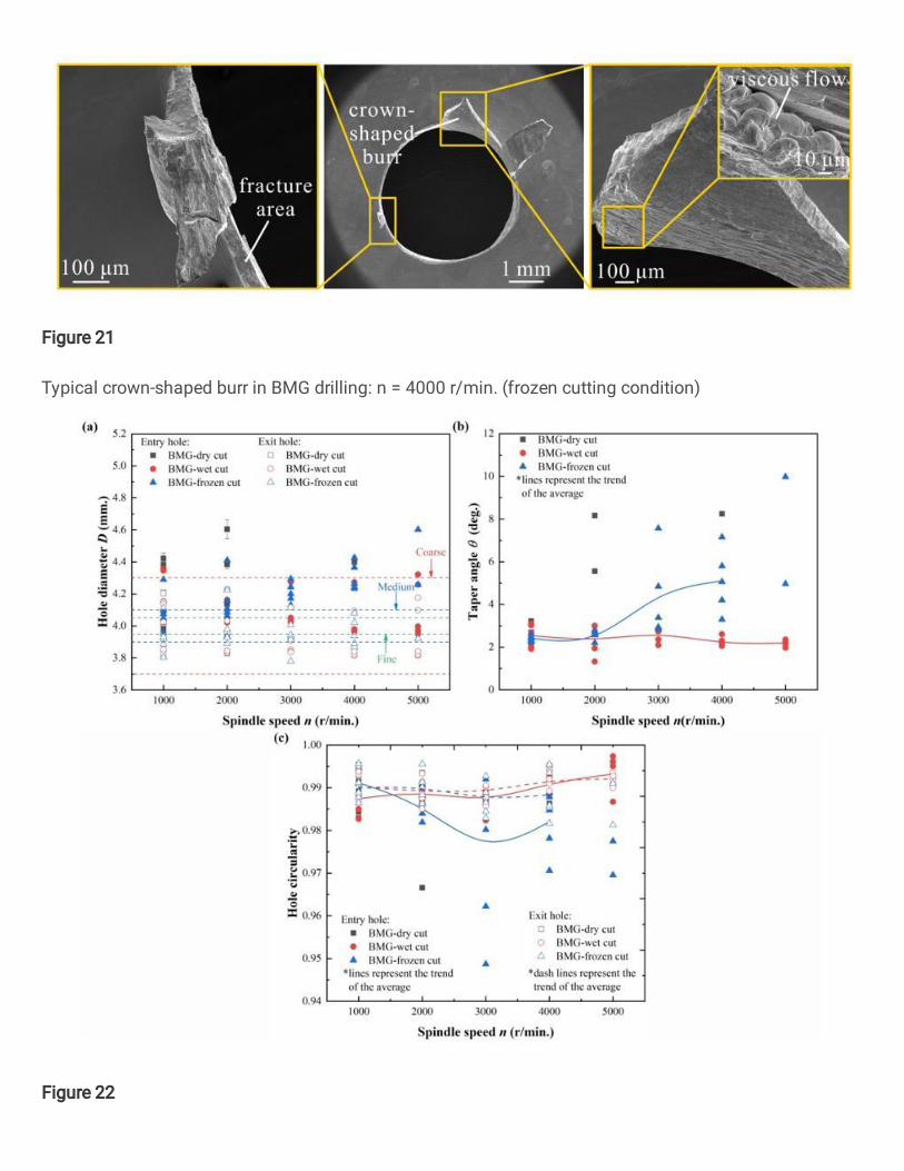
Figure 21
Typical crown-shaped burr in BMG drilling: n = 4000 r/min. (frozen cutting condition)
Figure 22

Holes accuracy evaluations: (a) hole diameter, (b) taper angle; (c) hole circularity.