Embed Size (px)
Citation preview

Geol Rundsch (1997) 86: 426 - 438, Offprint 426 with Contributions to "Prediction in geology", Vrije Universiteit Amsterdam, February, 22nd-24th 1996
Original Paper
K. Thuro
Drillability prediction - geological influences in hard rock drill and blast tunnelling
Abstract* Usually the main subject in preliminary si-te investigations prior to tunnelling projects is the pre-diction of tunnel stability. During the last years in conventional drill and blast tunnelling, problems have occured also connected to the accurate prediction of drillability in hard rock. The drillability is not only de-cisive for the wear of tools and equipment but is - a-long with the drilling velocity - a standard factor for the progress of excavation works. The estimation of drillability in predicted rock conditions might bear an extensive risk of costs. Therefore an improved pre-diction of drilling velocity and bit wear would be de-sireable. The drillability of a rock mass is determined by various geological and mechanical parameters. In this report some major correlations of specific rock properties and especially geological factors with mea-sured bit wear and drilling velocity are shown.
Drilling velocity is dependent on a lot of geological parameters: Those principal parameters include join-ting of rock mass, orientation of schistosity (rock an-isotropy), degree of interlocking of microstructures, porosity and quality of cementation in clastic rock, de-gree of hydrothermal decomposition and weathering of a rock mass. Drilling bit wear increases with the equi-valent quartz content. The equivalent quartz content builds the main property for the content of wear-rele-vant minerals. For various groups of rock types dif-ferent connections with the equivalent quartz content could be detected. In sandstone bit wear is also depen-dent on porosity or the quality of the cementation. Fi-nally an investigation program is submitted, which helps to improve the estimation of rock drillability in planning future tunnel projects.
K. Thuro Lehrstuhl für Allgemeine, Angewandte und Ingenieur-Geologie, Technische Universität München D-85747 Garching, Germany Fax: +49 89 289 14382 e-mail: thuro@ mineral.min.chemie.tu-muenchen.de
Key words: Drillability ⋅ Drilling rate, Bit wear, Destruction work, Anisotropy, Joint spacing, Equivalent quartz content, Porosity
Drilling equipment - technical introduction
For drilling blastholes in hard rock, today the rotary percussive drilling is standard in underground mining and tunnelling, providing maximum performance un-der most circumstances (Cohrs 1988). The hydraulic drill hammer is a combination of a rotary drilling ma-chine and a percussive drill and uses a separate rotary and percussive mechanism.
Whereas percussive drilling is controlled by jerkily moving of the drilling rod with only a loose contact of the drilling bit to the bottom of the borehole, rotary percussive drilling is characterized by continuous ro-tation - comparable to rotary drilling. By means of high feed pressure (12 - 20 kN), lying more than a de-cade above those in percussive drilling, the drilling bit is always tight to the bottom of the borehole. Since the torques are much stronger, crushing work is carried out also by shearing between the impacts.
Fig. 1 Operation of rotary percussive drilling and the main machi-ne parameters
Regarding just the procedure, the rotary percussive drilling is superior to the rotary drilling and the per-cussive drilling (Feistkorn 1987). The hydraulics faci-litate an optimum energy transfer from the percussive mechanism to the drilling rod. Parameters are the

427
technical specifications of the drill hammer, flushing system and the design of the drilling bit (Fig. 1).
Fig. 2 Drilling rig: Atlas Copco Rocket Boomer H 175 with 3 booms and service platform
Typical tunnelling rigs consist of a diesel-hydraulic rubber-wheeled tramming carrier, carrying up to three booms with hydraulic drifter feeds and rock drills. The range comprises units for hydraulic drilling with a se-lection of of different carriers, booms, feeds, and rock drills (Fig. 2).
Fig. 3 Hydraulic boom BUT 35 of the AC-Rocket Boomer H 175. Centre-mounted feed with double rotation devices, which makes it possible to position the feed vertically on both sides of the boom, with accurate parallel holding, roof drilling and cross-cuts
For example the COP 1440 hammer (20 kW impact power) mounted on the AC Rocket Boomer H 175 is the most popular hydraulic rock drill presently in use. Features such as rapid and exact boom positioning with roof drilling and cross-cuts are performed with the BUT 35 boom shown in Fig. 3.
Fig. 4 Typical button drill bits with six, seven, eight and nine but-tons and different flushing systems mainly used in hard rock
Fig. 4 shows typical button bits used in underground excavation in rotary percussive drill rigs. The drilling bit is the part of the rig which carries out the crushing work. The bit consists of a carrier holding the actual drilling tools: buttons of hard metal (wolfram carbide with a cobalt binder, MOHS´ hardness 9½). Possible sorts of button types and their main characteristics are shown in Fig. 5.
(semi-)ballistic
spherical
conical(ballistic)
! "non aggressive" shape! minimum drilling rates! low bit wear! excavation mainly
by impact
! "aggressive" shape! moderate drilling rates! moderate bit wear! excavation mainly
by shearing / cutting
! "very aggressive" shape! maximum drilling rates! high bit wear! excavation mainly
by shearing / cutting
Button Types Characteristics
Fig. 5 Button types of drilling bits used for rotary percussive dril-ling and their main characteristics
The shape of the button and the design of the bit (ge-ometry and arrangement of buttons, flush holes and draining channels) have a strong influence on bit wear and drilling performance. In Fig. 6 drilling rates rela-tive to the average of the quickest bit type are plotted comparing 6-, 7-, 8- and 9-button bits. For example, using ballistic 9-button bits, a maximum penetration performance has been obtained in (tough) quartz phyl-lite of the Innsbruck area. This impression is less distinctive in brittle rock types as can be seen in limestone from the German Muschelkalk. The highest drilling rates in this limestone have been archieved u-sing an 8-button bit, giving an optimum between but-ton stress and button area in brittle rock.

428
70
75
80
85
90
95
100
105
drilli
ngra
te[%
]
6 x 45 s 7 x 45 s 8 x 45 s 8 x 45 b 9 x 45 s 9 x 45 b
button bit type
quartz phyllite (Innsbrucker Quarzphyllit)
70
75
80
85
90
95
100
105
6 x 45 s 7 x 45 s 8 x 45 s 8 x 45 b 9 x 45 s 9 x 45 b
limestone (Muschelkalk)
drilli
ngra
te[%
]
button bit type Fig. 6 Drilling rates in quartz phyllite and limestone depending on the button type and drilling bit. 9 x 45 b = 9 button type, ∅ 45 mm, b ballistic; s spherical
Parameters of Drillability Drillability is a term used in construction to describe the influence of a number of parameters on the drilling rate (drilling velocity) and the tool wear of the drilling rig. As could be seen in the technical introduction, drillability is - first of all - influenced by the machine parameters of the chosen drilling rig. Therefore, only tunnel projects with the same drilling equipment can be used for drillability studies (Thuro 1996). The in-teraction of the main factors is illustrated in Fig. 7.
Apart from technical parameters, especially the ge-ological parameters will basically influence the dril-ling performance and the wear of the drilling rig (Fig. 8). The specific characteristics of rock material and rock mass may be at least partly put into figures with the help of mechanical rock properties. But rock mass conditions also highly depend on the geological histo-ry, weathering conditions, hydrothermal decom-position and the structure of discontinuities. Therefo-re, one has to go through three levels of investigation: mineral - rock type - and rock mass - meaning also three levels of dimension!
Working Processexcavation system & logistics,
operation & maintenance of the tunnelling rig
Geological ParametersRock & Rock Massmechanical
rock properties,
rock mass
conditions
Machine ParametersDrilling Rig
percussive
drill hammer,
power transfer,
drilling bit
Drillability
tunnellingperformance
drilling velocity
wear of drilling toolsdrilling bit wear
Fig. 7 Illustration of the term "drillability" and the main influen-cing parameters.
mineral
rock
rock mass
mineral compositionmicro fabric
elastic/plastic behaviourmechanical rock properties
rock mass conditionsdiscontinuities
equivalent quartz contentporosity / cementation
destruction workcompressive strengthYoung's modulustensile strength
rock density
spacing of discontinuitiesstatus of weatheringhydrothermal decomposition
anisotropy
ratio of compressive andtensile strength
Fig. 8 Geological parameters: General view of the characteristics of mineral, rock and rock mass
The last important factor influencing drillability is the working process itself. Firstly, smooth operation and permanent maintenance of the tunnelling rig con-tributes to a successful drilling performance. Second-ly, a high penetration rate at the tunnel face does not automatically lead to a high performance of the tunnel heading (Thuro and Spaun 1996a). Therefore, it is a matter of understanding the entire excavation system before applying expertise to the investigation of drilla-bility.
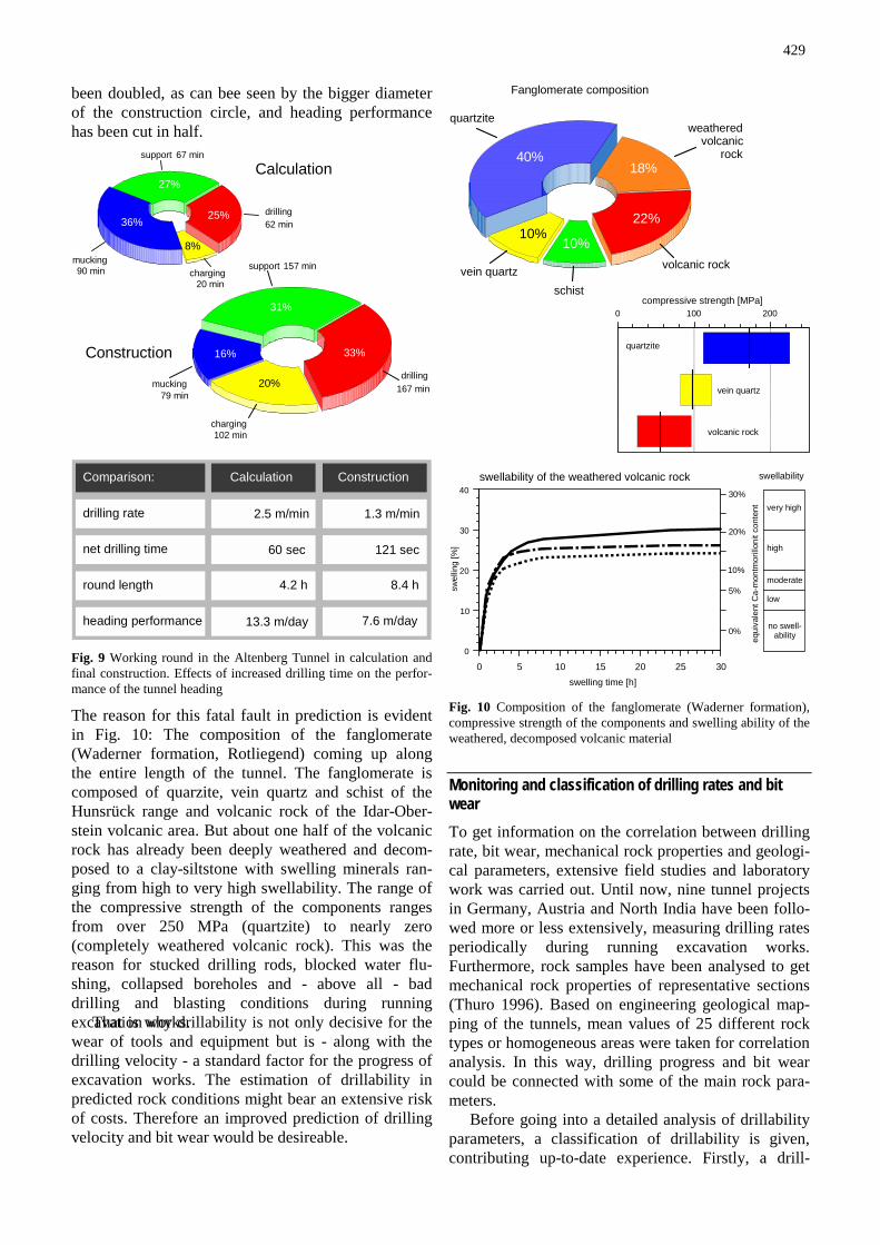
The necessity of drillability studies But why is prediction of drillability necessary? The following figures will show the effects of increased drilling time on the performance of the tunnel heading. As an example, the excavation works of the Altenberg Tunnel in Idar-Oberstein are presented as circle dia-grams in Fig. 9 - in calculation (left side) and during final construction (rigth side; Thuro 1996).
As can be seen from the drilling segment, the entire drilling time of one round has increased nearly three times from calculation to final construction. The time for charging of the explosives during construction has increased five times as compared with calculation. Fi-nally, the time for excavating one entire round has be-
429
been doubled, as can bee seen by the bigger diameter of the construction circle, and heading performance has been cut in half.
drilling
chargingmucking
support
Calculation
Construction
67 min
90 min
62 min
20 min
27%
36% 25%
8%
167 min
102 min
79 min
157 min
33%
drilling
charging
mucking
support
31%
33%
20%
16%
net drilling time
round length
heading performance
Construction
8.4 h
7.6 m/day
121 sec
Calculation
60 sec
4.2 h
13.3 m/day
Comparison:
1.3 m/min2.5 m/mindrilling rate
Fig. 9 Working round in the Altenberg Tunnel in calculation and final construction. Effects of increased drilling time on the perfor-mance of the tunnel heading
The reason for this fatal fault in prediction is evident in Fig. 10: The composition of the fanglomerate (Waderner formation, Rotliegend) coming up along the entire length of the tunnel. The fanglomerate is composed of quarzite, vein quartz and schist of the Hunsrück range and volcanic rock of the Idar-Ober-stein volcanic area. But about one half of the volcanic rock has already been deeply weathered and decom-posed to a clay-siltstone with swelling minerals ran-ging from high to very high swellability. The range of the compressive strength of the components ranges from over 250 MPa (quartzite) to nearly zero (completely weathered volcanic rock). This was the reason for stucked drilling rods, blocked water flu-shing, collapsed boreholes and - above all - bad drilling and blasting conditions during running excavation works. That is why drillability is not only decisive for the wear of tools and equipment but is - along with the drilling velocity - a standard factor for the progress of excavation works. The estimation of drillability in predicted rock conditions might bear an extensive risk of costs. Therefore an improved prediction of drilling velocity and bit wear would be desireable.
Fanglomerate composition
volcanic rock
weatheredvolcanic
rock
quartzite
vein quartzschist
40%18%
22%
10%10%
0 100 200compressive strength [MPa]
quartzite
vein quartz
volcanic rock
swellability
very high
moderate
high
no swell-ability
low5%
10%
20%
30%
0%
equi
vale
ntC
a-m
ontm
orill
onit
cont
ent
swellability of the weathered volcanic rock
0
10
20
30
40
swel
ling
[%]
0 5 10 15 20 25 30swelling time [h]
Fig. 10 Composition of the fanglomerate (Waderner formation), compressive strength of the components and swelling ability of the weathered, decomposed volcanic material
Monitoring and classification of drilling rates and bit wear To get information on the correlation between drilling rate, bit wear, mechanical rock properties and geologi-cal parameters, extensive field studies and laboratory work was carried out. Until now, nine tunnel projects in Germany, Austria and North India have been follo-wed more or less extensively, measuring drilling rates periodically during running excavation works. Furthermore, rock samples have been analysed to get mechanical rock properties of representative sections (Thuro 1996). Based on engineering geological map-ping of the tunnels, mean values of 25 different rock types or homogeneous areas were taken for correlation analysis. In this way, drilling progress and bit wear could be connected with some of the main rock para-meters.
Before going into a detailed analysis of drillability parameters, a classification of drillability is given, contributing up-to-date experience. Firstly, a drill-

430
ability classification should rely on values easily ob-tained on the site. Secondly, the parameters should be expressive and provide a good resolution of drilling ra-te and wear characteristic. The system proposed here is based on net drilling velocity, measured at the tun-nel face and drilling bit wear recorded as the bit life-span.
drilling rate =borehole depth
net drilling time
meters
minutes
drilling bit wear
drilling velocity
total boremeters
number of drill bits
meters
bitsbit life-span =
Formula 1 Determination of drilling velocity and drilling bit wear
The drilling performance is taken as the drilling ve-locity or drilling of one simple borehole. The drilling bit wear is taken as the bit life, which means the total of boremeters drilled with one bit (Formula 1).
To get an impression of how wide values of bit wear and drilling rates may vary, mean values of diffe-rent rock types or homogeneous areas derived from 25
case studies in 9 tunnel projects in Germany, Austria and overseas (North India) were plotted into the chart in Fig. 11.
The investigations were carried out using a 20 kW borehammer (Atlas Copco COP 1440). The matrix was based on the experience, that high drilling rates (3 - 4 m/min) and low bit wear (1500 - 2000 m/bit) should be described as "fair" drillability. The drilling rates range from 1 meter per minute to about 5 meters per minute. The bit life-span ranges from 50 meters to over 2,000 meters per bit. Therefore drillability ranges in our classification from extremely poor to easy.
Mechanical rock properties The most frequently used rock properties are the un-confined compressive strength, the Young´s modulus and the tensile strength. As a derived rock property, the ratio of unconfined compressive strength and ten-sile strength often is designated as toughness (or britt-leness) of a rock material. Many authors tend to take one or more of those properties as main parameters of drillability (Schimazek & Knatz 1970, Wanner 1975, Habenicht & Gehring 1976, Blindheim 1979, Movin-kel & Johannessen 1986). Thus extensive rock testing has been carried out based on the ISRM suggested me-thods (Brown 1981, ISRM 1985) to gain re-presentative mean values of the properties of the dril-led rock types.
Regarding the drilling rig, the drilling process is fundamental for the choice of the investigation pa-
very high
high
med miu
low
very low
Dril
ling
Velo
city
extre
mel
yhi
gh
high
mod
erat
e
very
high
low
very
low
Bit Wear
0
1
2
3
4
5
0 500 1000 1500 2000 2500
normal
poor
very poor
easy
poor
extremely
Drillability
not btained yet
o
percussive drill COP 1440 - 20 kW
[m/bit]
drilli
ngra
te[m
/min
]
sandstones phyllites & gneiss
marble
limestone & marlconglomerate &fanglomerate
quartz-mica-schistquartziteamphibolite
not obtained yet
Fig. 11 Classification diagram enclosing 25 case studies of different rock types or homogeneous areas derived from 9 tunnel projects

431
rameters. In Fig. 12 the crushing mechanism is illustra-ted. Coming from studies by high-speed photography and analysis of thin sections of rock below the area of disc cutter tools of tunnel boring machines, three main destruction mechanisms could be detected (Ozdemir et al. 1977, Wang et al. 1978, Blindheim 1979). Those results can be generalised and transferred on the crush-ing process below the buttons of a drilling bit.
10 mm
drilling bit
1 crushed rock powder 2 radial cracks 3 detached fragments
button button1
22
3
2
3
rotationrotation
pene
tratio
n
Fig. 12 Crushing process in rotary percussive drilling. Destruction mechanism under the bit buttons
Around the contact of the button a new state of stress is induced in the rock, where four important de-struction mechanisms can be distinguished: 1) Under the bit button a crushed zone of fine rock
powder is formed (impact).
2) Starting from the crushed powder zone, radial cracks are developed (induced tensile stress).
3) When stress in the rock is high enough (if enough cracks exist ± parallel to the bottom of the bore-hole), larger fragments of the rock can be sheared off between the button grooves (shear stress).
4) In addition to the mechanisms above stress is in-duced periodically (dynamic process). Examining the drilling mechanism it is obvious,
that besides compressive and tensile strength (percus-sive process) and shear strength (bit rotation) the e-lastic characteristics of rock material is of crucial im-portance. To be precise, the bit always drills through pre-cracked rock (see Müller-Salzburg 1963: 104). Therefore the so-called specific destruction work Wz has been introduced (Thuro 1996, Thuro & Spaun 1996a,b), as a measurement for the quantity of energy, required for destruction of a rock sample or - in other words - the work, necessary to build new surfaces (or cracks) in rock. As a product of both - stress and strain - destruction work represents the work of shape alte-ring including the post failure section (Fig. 13).
stre
ssσ
strain ε
post-failure-sectionpre-failure-section
destruction work
W = dz σ ε
failure point
unconfinedcompressiontest
UCS
Fig. 13 Estimation of the specific destruction work Wz from the stress-strain curve of a rock sample under unconfined compression. UCS unconfined compressive strength
In Fig. 14 drilling rates of the previously mentioned rock material is plotted against destruction work inc-luding clay-siltstone, sand- and limestone, conglome-rate, marl, marble, schist and different cristalline rock. The destruction work proved to be a highly significant parameter for correlation with the drilling performan-ce. The chart indicates the close correlation between drilling velocity and destruction work.
0
1
2
3
4
5
drilli
ngra
te[m
/min
]
0 100 200 300 400 500destruction work [kJ/m ]3
sand- & claystone phyllite & gneissmarble
limestone & marlconglomerate &fanglomerate
silicic dolomite
standard deviation
y=5.49-0.60·ln x y =0.28m/min n=23 R =89%σ(n-1)2
Fig. 14 Drilling rates, correlated with destruction work of 23 rock types. The correlation is very good
In contrast to the described connection, correlations between the conventional mechanical rock properties (unconfined compressive and tensile strength, Young's modulus and the ratio of unconfined compressive strength and tensile strength "toughness") and drilling rates show less significance (see Thuro and Spaun 1996 b).

432
Geological parameters Although mechanical properties allow prediction of drilling performance to be more precise, geological in-fluences are even more decisive for drilling velocity as well as for the bit life. There are several geological in-fluences though only some can be mentioned here: 1. anisotropy - orientation of discontinuities related to
the direction of testing or drilling 2. spacing of discontinuities 3. mineral composition - equivalent quartz content 4. pore volume - porosity of the micro fabric
Hydrothermal decomposition of rock material very often shows the same effects as the status of weathe-ring. Some of the possibly connected problems have already been discussed in this paper.
Anisotropy Of course, rock properties and drilling rates are also highly dependent on the orientation of weakness pla-nes related to the direction of testing or drilling. This has been discussed in detail by Thuro & Spaun (1996, also see Spaun and Thuro 1994).
When the direction of drilling is at right angles to the orientation of foliation (Fig. 15, left side), rock material is compressed at right angles but sheared pa-rallel to it. Although cracks will develop radial to com-pression, the cracks parallel to the bottom of the borehole will be used for chipping. Usually in this ca-se the highest drilling velocities are obtained, because of the favourable schist orientation. Drilling is control-led by the shear strength of the foliated rock material. The minimum destruction work causes large sized chips and a maximum drilling performance (Fig. 16).
If the drilling axis is oriented parallel to foliation (Fig. 15, right side), compression also is parallel but shear stress is at right angles. It should be clear, that fewer cracks will develop for reasons of higher strength at right angles to foliation. Drilling is control-led by the tensile strength parallel to the foliation pro-ducing small-sized fragments and a minimum drilling performance (Fig. 16).
It is certain, that in the parallel case, rock proper-ties are the highest and drilling rates are low. In addi-tion, blasting conditions are often related to drilling. Thus, if the tunnel axis is parallel to the main foliati-on, drilling and blasting conditions are supposed to be very poor.
As a further result of anisotropy, problems may oc-cure when drilling direction is diagonal to the tunnel axis: When the angle between drilling and tunnel axis is acute-angled, drifter rods are deviated into the dip direction of foliation, if obtuse-angled, into the normal direction of foliation. In any case, drill tracks may be seen as curves and produce distinct borehole deviation and a “geologically caused” overbreak.
compressive/tensile stress
shear stress
UCS TS UCS TS
testingarrangements
shear stress
Fig. 15 Drilling process according to different orientations of folia-tion (after Spaun and Thuro 1994).
25
50
75
100
drilli
ngra
te[%
]
drilling rate
tensile strength25
50
75
100
indi
rect
tens
ilest
reng
th[%
]
dip angle of foliation90 75 60 45 30 15 0
high tensile stress low tensile stress
y = a + b·cos xgraph equation
Fig. 16 Drilling rate and tensile strength plotted against the orientation of foliation
Spacing of discontinuities Of course, drilling rates are also dependent on spacing of discontinuities in rock mass. Discontinuities are, as a law, weakness planes in rock mass - thus Müller-Salzburg (1963) talks about rock mass as "broken rock". The spacing of joints could also be described as "joints per meter" and is another parameter for the pre-cracking of rock.
In the chart of Fig. 17 the influence of discontinui-ties is not visible, if the spacing is large against the dimensions of the borehole. When the joints get clo-ser, the drilling velocity increases up to the double. But the connected problem is borehole instability, cau-sing hole collapses and timeconsuming scaling of the established blasthole. By this means, the efforts of fast drilling, especially in fault zones, may be rendered u-seless very soon.

433
spacing largeagainst dimension
of borehole
collapse ofboreholescommon
2
3
4
5
drill
ing
rate
[m/m
in]
faul
tzo
ne
extre
me
clos
ely
very
clos
ely
clos
ely
med
ium
wid
ely
very
wid
ely
joint spacing
80
100
120
140
160
180
200
0,6 cm 2 cm 20 cm 200 cm6,3 cm 63 cm
%limestone (middle Muschelkalk)
Fig. 17 Correlation between drilling rate and joint spacing in li-mestone of the middle Muschelkalk
Equivalent quartz content Having discussed some factors influencing drilling ra-tes, parameters for predicting the drilling bit wear are now mentioned. As a leading parameter, the wear of drilling bits has been examined in different rock types. Other tools such as drifter rods, couplings and shank adapters have a life-span on average ten times the one of button bits and thus are not suitable.
Technical parameters are not really suitable for drillability studies though there are about 200 hardness tests for rock characterization (Atkinson 1993, West 1989, Brook 1993, Nelson 1993). Much of them have been introduced for a special purpose and have not been developed further. Only few have gained interna-tional attention such as the drilling rate index DRI (Selmer-Olsen and Blindheim 1970) or the Cerchar ab-rasivity index CAI (Valantin 1973, Suana and Peters 1982).
The point is, there is no single physical property in existence to quantify and describe ´´hardness’’ as if it is the uniaxial compressive strength for stress. Also a lot of petrographic parameters such as rock texture and mineral fabric have been discussed to be used for pre-dicting tool wear and drillability (Howarth and Row-lands 1987). But the performed structural methods are very time consuming and thus have not been applied in practice.
It is clear, that tool wear is predominantly a result of the mineral content harder than steel (Mohs hard-ness ca. 5.5), especially quartz (Mohs hardness of 7). To include all minerals of a rock sample, the equiva-lent quartz content has been determined in thin secti-ons by modal analysis - meaning the entire mineral content refering to the abrasiveness or hardness of quartz (Formula 2). Therefore each mineral amount is multiplied with its relative Rosiwal abrasiveness to quartz (with quartz being 100%, Rosiwal 1896, 1916).
An appropriate correlation between Mohs hardness and Rosiwal abrasiveness is given in Fig. 18. When
the Mohs hardness is known, the abrasiveness of mine-rals can be estimated by this chart with satisfactory accuracy (within a half degree of Mohs hardness).
equ =
equivalent quartz content
Σn
i=1A Ri i⋅
A - mineral amount [%]R - Rosiwal abrasiveness [%]n - number of minerals
Formula 2 Determination of the equivalent quartz content
0
1
2
3
4
5
6
7
8
9
Moh
sha
rdne
ss
1 10 100 1000Rosiwal abrasiveness
quartz
y = 2.12 + 1.05·ln x y = n=24 R =95%σ(n-1) ½ 2
Fig. 18 Correlation between Rosiwal abrasiveness and Mohs hard-ness, enclosing 24 different minerals (excluding diamond)
hydrothermaly decomposed
0
500
1000
1500
2000
2500
0 20 40 60 80 100
0
500
1000
1500
2000
2500
0 20 40 60 80 100
0
500
1000
1500
2000
2500
0 20 40 60 80 100
0
500
1000
1500
2000
2500
0 20 40 60 80 100
0
500
1000
1500
2000
2500
0 20 40 60 80 100
low
moderate
high
very high
extremely h.
Bit Wear
very low
defects of binder,porosityhydrothermal
decomposition
main graph
bitl
ife-s
pan
[m/b
it]
equivalent quartz content [%]
sandstone phyllite & gneissmarble
limestone & marlfanglomerate &conglomerate
crystalline rock
Fig. 19 Bit life of different rock types correlated with the equiva-lent quartz content enclosing 42 case studies in 8 tunnel projects
The method of determining the equivalent quartz content is wide-spread among tool manufacturers, en-gineers and engineering geologists for preliminary site investigations prior to tool wear problems.
In Fig. 19 the bit life of different rock types is cor-related with its equivalent quartz contents. It is visible

434
that bit wear raises mainly with increasing equivalent quartz content. But obviously some kinds of rock have their own curves: (a) sandstones, especially those with higher porosity, often corresponding with a defect in the silicic cementation; and (b) hydrothermally de-composed crystalline rock.
In each of those special rock types the interlocking of the grains in the microfabric is "disturbed". There-fore, for purposes of prediction, each rock type must be discussed individually. In Fig. 20 a rock family - something like a "normal facies" - of limestone, marl, conglomerates, together with phyllites and marbles has been built to be described by a logarithmic regression curve.
For the chosen rock family the relation is very clo-se and may be used for a forecast of bit wear, when the equivalent quartz content is determined by a thin sec-tion modal analysis.
0
500
1000
1500
2000
2500
0 20 40 60 80 100
limestone, marl, conglomerates, phyllites, marbles
standard deviation
y=3131-624·ln x y =144m/bit n=22 R =95%σ(n-1)2
bitl
ife-s
pan
[m/b
it]
equivalent quartz content [%]
low
moderate
high
very high
extremely h.
Bit Wear
very low
Fig. 20 Bit life-span of limestone, marl, conglomerates, together with phyllites and marbles and corresponding equivalent quartz content
Porosity and binder defects For sandstones and decomposed rock other relation-ships must be discussed. The expected connection is also detected when plotting the porosity of sandstones instead of the equivalent quartz content into the dia-gram (Fig. 21). Porosity is measured here as a function of dry density of rock material and ranges from a com-pact (dense) to a totally decomposed silicic binder-free fabric.
There seems to be a correlation between the porosi-ty of the rock and technical parameters, such as bit wear (Fig. 21), drilling rates (Fig. 22) and - naturally - mechanical rock properties such as unconfined com-pressive strength (Fig. 29) and destruction work (Fig. 30). Although the number of cases in each chart is quite low, the good correlation coefficient suggests a close connection. The data were collected in the Schönrain Tunnel near Würzburg, where mainly rock of the middle und upper Bunter sandstone has been en-countered and in the Achberg Tunnel nearby Unken in the Werfen sandstone formation.
increasing
low
moderate
high
very high
extremely h.
Bit Wear2 2,1 2,2 2,3 2,4 2,5 2,6
dry density [g/cm ]3
0
500
1000
1500
2000
bitl
ife-s
pan
[m/b
it]
25 20 15 10 5 0porosity [%]
hydrothermallydecomposed
compact
porosity
defect binder
y =136m/bity=174+60?x n=8 R =90%σ(n-1)2
Fig. 21 Correlation of bit life-span and porosity (dry density) in sandstones
0
1
2
3
4
5
6dr
illin
gra
te[m
/min
]
25 20 15 10 5 0porosity [%]
very high
high
moderate
low
very low
Drilling velocity
COP 1440 - 20 kW
7-button bits2 2,1 2,2 2,3 2,4 2,5 2,6
clay-silt-stone
dry density [g/cm ]3
y =0.12m/bity=1.83+0.12·x n=8 R =98%σ(n-1)2
Fig. 22 Correlation of drilling rates and and porosity (dry density) in sandstones

435
Fig. 23 Hard, quartzitic Bunter sandstone with a very dense and compact fabric. No pores can be seen and the fracture runs through each individual quartz grain ("intragranular failure"; picture length approx. 1 mm)
Fig. 24 Hard Bunter sandstone with a less dense fabric. Fracturing is dominated by intergranular (grain-to-grain) failure. Larger hexa-hedric quartz crystals growing on grains are developing out of small granules of silicic binder (picture length approx. 1 mm)
Fig. 25 Hydrothermally decomposed Bunter sandstone, characteri-sed by a porous fabric with a clayey binder in replacement of the original, silicic cement (picture length approx. 5 mm)
Fig. 26 Small hexahedric granules of silicic cement growing on quartz grains (picture length approx. 0.1 mm)
Fig. 27 Clayey binder of the decomposed Bunter sandstone sho-wing kaolinite crystals growing in the twinning lamellae of a plagi-oclase crystal (picture length approx. 0.1 mm)
Fig. 28 In the grain gaps, small calcite rhombohedrons are growing as secondary binder (picture length approx. 0.14 mm)

436
0
20
40
60
80
100
120
unco
nfin
edco
mpr
essi
vest
reng
th[M
Pa]
25 20 15 10 5 0porosity [%]
y =8,1MPay=168-53 ln x n=8 R =95%⋅ σ(n-1)2
2 2,1 2,2 2,3 2,4 2,5 2,6
clay-silt-stone
very high
high
moderate
low
compressivestrength
very low
after ISRM
dry density [g/cm ]3
Fig. 29 Correlation of unconfined compressive strength and poro-sity (dry density) in sandstones
0
50
100
150
200
250
dest
ruct
ion
wor
k[k
J/m
]3
25 20 15 10 5 0porosity [%]
2 2,1 2,2 2,3 2,4 2,5 2,6
dry density [g/cm ]3
clay-silt-stone
y =30y=327-103 ln x n=8 R =83%⋅ σ(n-1) kJ/m3 2
Fig. 30: Correlation of destruction work and porosity (dry density) in sandstones
The fabric of the different stages of porosity (or dry density) can be visualized by raster electron micro-scope photography. In Fig. 23 a very dense and com-pact fabric of a hard, quartzitic Bunter sandstone is
shown where fracture is characterized by intragranular failure.In Fig. 24, a hard Bunter sandstone with a hig-her porosity is visible, suggesting a fabric less dense than before. The silicic cement does not fill every gap between the quartz grains but the cementation is more than just a grain-to-grain binding (intergranular failu-re). The small granules of silicic cement are also he-xahedric, as can bee seen by increased enlargement in Fig. 26. The hydrothermally decomposed Bunter sand-stone of Fig. 25 is characterised by a porous fabric with a clayey binder. Clay has replaced the original silicic cement. The rock has changed its colour from originally red to a flat whitish-grey, thus indicating hydrothermal activity dating from a fault zone ("Harrbacher Sprung") in the Schönberg Tunnel. The contact of the grains is not solid anymore but only we-akly cemented and the surface of the grains looks "dirty".
In Fig. 27 the clayey binder of the decomposed Bunter sandstone is visible, showing kaolinite crystals growing in the twinning lamellae of a plagioclase crys-tal. The small flakes probably are fed into the grain gaps by circulating ground water.
In the grain gaps, small calcite rhombohedrons grow as secondary binder (Fig. 28). It looks like the si-licic binder has been removed from the sandstone to-gether with the red colour, leaving behind some clayey material and calcitic cement.
Conclusion After all these observations, it is clear, that neither la-boratory and field testing alone, geology alone, nor experience alone and equipment design and operation expertise alone can lead to the point where drillability is anything like a clearly defined formula.
Firstly, with the discovered correlation charts for
destruction workcompressive strengthYoung's modulustensile strengthratio of compressive /
tensile strengthrock density / porosity" influence of anisotropy
or other factors
Investigation Program
preliminary site investigations engineering geological mappingrock & soil description and classificationquantitative description of discontinuitieson basis of IAEG and ISRM standardization
mechanical rock properties
mineral compositionmicro fabric
sampling out of drilling coresif possible, out of an investigation tunnel
equivalent quartz contentdegree of interlocking
anisotropyspacing of discontinuitiesstatus of weatheringhydrothermal decomposition
petrographic description
Fig. 31 Proposal of an investigation program for preliminary site investigations

437
mechanical and petrographic rock properties, it should be possible to predict drilling rates and bit wear for the examined rock types in a satisfactory manner. But be-sides rock properties, the main problem is the variety of geological phenomena, which cannot be put into figures and rock properties.
Nevertheless in preliminary site investigation the most important thing to do is simple and basic geolo-gical mapping. This sounds simple. But it is extremely necessary to keep in mind all the parameters possibly influencing drilling performance. Secondly, it is very important to prepare all rock and soil descriptions in a way engineers are able to understand. Only in such a manner is it possible to raise the level of geological contribution to underground construction, and the ent-ire excavation system must be understood before applying geological expertise to the solution of expec-ted or developing drillability problems
In Fig. 31 an investigation program for preliminary site investigations is presented, which should help to improve the estimation of rock drillability in planning future tunnel projects, trying to integrate all discussed knowledge bases.
References Atkinson H (1993) Hardness tests for rock characterization. In:
Hudson J (ed) Comprehensive rock engineering. Principles, practice & projects. Vol. 3: Rock testing and site characteriza-tion. Pergamon, Oxford, pp 105-117
Blindheim OT (1979) Drillability predictions in hard rock tunnel-ling. Tunnelling 284-289
Brook N (1993) The measurement and estimation of basic rock strength. In: Hudson J (ed) Comprehensive rock engineering. Principles, practice & projects. Vol. 3: Rock testing and site characterization. Pergamon, Oxford, pp 41-81
Brown ET, ed (1981) Rock characterization, testing and monito-ring. ISRM suggested methods. Pergamon, Oxford, pp 1-221
Cohrs HH (1988): Untergrundkämpfer. Bohrwagen für den Tun-nel- und Stollenbau. BD Baumaschinendienst 24: 344-350
Feistkorn E (1987) Bohr- und Sprengtechnik. Teil A: Bohrtechnik. In: Taschenbuch für den Tunnelbau 1988, 12, Dtsch Gesell-schaft für Erd- und Grundbau e.V., Essen, pp 217-273.
Habenicht H, Gehring K (1976) Gebirgseigenschaften und maschi-neller Tunnelvortrieb. Berg- und Hüttenmännische Monatshef-te 121: 506-514.
Howarth DF, Rowlands JC (1987) Quantitative assessement of rock texture and correlation with drillability and strength pro-perties. Rock Mech Rock Eng 20: 57-85
ISRM (1985) Suggested method for determining point load strength. ISRM Commission on Testing Methods, Working Group on Revision of the Point Load Test Method. Int J Rock Mech Min Sci Geomech Abstr 22: 51-60
Movinkel T & Johannessen O (1986) Geological parameters for hard rock tunnel boring. Tunnels Tunneling 4: 45-48.
Müller-Salzburg L (1963) Der Felsbau. Bd.I, Theoretischer Teil, Felsbau über Tage, 1. Teil. Enke, Stuttgart 1-624
Nelson PP (1993) TBM performance analysis with reference to rock properties. In: Hudson J (ed) Comprehensive rock engi-neering. Principles, practice & projects. vol. 4. Excavation, Support and Monitoring. Pergamon, Oxford, pp 261-291
Ozdemir L, Miller R, Wang FD (1977) Mechanical tunnel boring, prediction and machine design. Annual report, CSM APR 73-07776-A03
Rosiwal A (1896) Neue Untersuchungsergebnisse über die Härte von Mineralien und Gesteinen. Verhandlg d kk geol R-A Wien: 475-491.
Rosiwal A (1916) Neuere Ergebnisse der Härtebestimmung von Mineralien und Gesteinen. Ein absolutes Maß für die Härte spröder Körper Verhandlg d kk geol R-A Wien: 117-147.
Schimazek J, Knatz H (1970) Der Einfluß des Gesteinsaufbaus auf die Schnittgeschwindigkeit und den Meißelverschleiß von Streckenvortriebsmaschinen. Glückauf 106: 274-278.
Selmer-Olsen R, Blindheim OT (1970) On the drillability of rock by percussive drilling. Proc 2nd Cong of the Int Soc for Rock Mech, Belgrade, pp 65-70
Spaun G, Thuro K (1994): Untersuchungen zur Bohrbarkeit und Zähigkeit des Innsbrucker Quarzphyllits. Felsbau 12: 111-122
Suana M, Peters T (1982) The cherchar abrasivity index and its re-lation to rock mineralogy and petrography. Rock Mech 15: 1-7
Thuro K. (1996) Bohrbarkeit beim konventionellen Sprengvor-trieb. Geologisch-felsmechanische Untersuchungen anhand sieben ausgewählter Tunnelprojekte. Münchner Geologische Hefte Reihe B Angewandte Geologie B1: 1-145
Thuro K, Spaun G (1996a) Drillability in hard rock drill and blast tunnelling. Felsbau 14: 103-109
Thuro K, Spaun G (1996b) Introducing `destruction work´ as a new rock property of toughness refering to drillability in con-ventional drill- and blast tunnelling. In: Barla G. (ed) Eurock ´96. Prediction and performance in rock mechanics and rock engineering, vol. 2. Balkema, Rotterdam, pp 707-713
Valantin A (1973) Test Cerchar por la mesure de la dureté et de l´abrasivité des roches. Annexe de l´exposée présenté aux Journées de Information “Techniques de creusement“, Lou-xembourg
Wang FD, Ozdemir L, Snyder L (1978) Prediction and experimen-tal verification of disk cutter forces in hard rock. Eurotunnel conference, Basel, 4: 1-44
Wanner H (1975) On the influence of geological conditions at the application of tunnel boring machines. Bull Int Ass Eng Geol 12: 21-28.
West G (1989) Rock abrasiveness testing for tunneling. Int J Rock Mech Min Sci Geomech Abstr 26: 151-160