Embed Size (px)
Citation preview
INTERNATIONAL PHASE OF OCEAN DRILLING (IPOD)DEEP SEA DRILLING PROJECTDEVELOPMENT ENGINEERINGDEEP SEA DRILLING PROJECTDEVELOPMENT ENGINEERINGTECHNICAL REPORT NO. 14
,
•
§ié
^M&
S
-;: wmm.DRILL STRING FAILURE ANALYSES
SCRIPPS INSTITUTION OF OCEANOGRAPHYUNIVERSITY OF CALIFORNIA AT SAN DIEGOCONTRACT NSF C-482PRIME CONTRACTOR: THE REGENTS, UNIVERSITY OF CALIFORNIA
H-
DISCLAIMER
This report was prepared by the Deep Sea Drilling Project, University ofCalifornia, San Diego as an account of work sponsored by the United StatesGovernment's National Science Foundation. Neither the University nor anyof their employees, nor any of their contractors, subcontractors, or theiremployees, makes any warranty, express or implied, or assumes any legalliability or responsibility for the accuracy, completeness or usefulnessof any information, apparatus, product or process disclosed, or representsthat its use would not infringe privately owned rights.
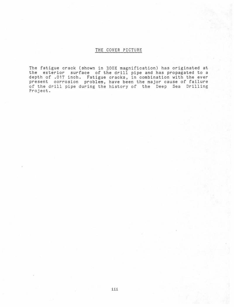
THE COVER PICTURE
The fatigue crack (shown in 300X magnification) has originated atthe exterior surface of the drill pipe and has propagated to adepth of .017 inch. Fatigue cracks, in combination with the everpresent corrosion problem, have been the major cause of failureof the drill pipe during the history of the Deep Sea DrillingProject.
iii
TECHNICAL REPORT NO. 14
DRILL STRING FAILURE ANALYSES
Prepared for theNATIONAL SCIENCE FOUNDATION
National Ocean Sediment Coring ProgramUnder Contract C-482
by the
UNIVERSITY OF CALIFORNIAScripps Institution of OceanographyPrime Contractor for the Project
November 1983
W. A. Nierenberg, Director M.N.A. PetersonScripps Institution of Oceanography Principal Investigator and
Project ManagerDeep Sea Drilling ProjectScripps Institution of Oceanography
INTRODUCTION
The Deep Sea Drilling Project (DSDP) became operational in August1968 with the successful sea trials of the drillship GLOMAR CHAL-LENGER. The vessel's mission was to recover cores of sedimentsand basement rock from the deep ocean for scientific study. Dur-ing the 15 years of exploration, a total penetration of 1,032,707feet was accummulated in the course of drilling and coring 1072holes at 614 sites. The deepest penetration beneath the seafloor was 5712 feet and the maximum penetration into basalticcrust was 3,543 feet. Wireline coring operations were undertakenwith drill string lengths to 23,111 feet.
For this demanding work, the project employed drill strings of5-inch, 19.5 lbs/ft, S-135 drill pipe with a minimum yieldstrength of 135,000 psi. A 4-inch minimum bore provided for highspeed wireline coring and high loads could be carried within thedrill pipe's 712,000 pound minimum yield load. Normal designloads were at 90% of minimum load.
During the 15 years of deep water operation, the high drillstring loads, vessel positioning losses, hard seafloors and acorrosive environment have all contributed to a number of majordrill string losses. Technical Report No. 14 is a summary andanalysis of these drill string and bottom hole assembly failures.Operating practices and means of failure reduction are also dis-cussed. Copies of formal metallurgical failure analyses by U. S.Steel Research and Battelle Houston Operations are included inthe appendix.
Vll
ACKNOWLEDGEMENTS
Technical Report No. 14 contains analyses of major drill stringfailures incurred during 15 years of Deep Sea Drilling Project(DSDP) wireline coring operations. Operating experience andmeans to reduce such losses is also described. This operationalexperience and failure analyses should be of interest to otheroperators in designing for similar deep water work.
The Project acknowledges the prompt and thorough failure analysesprovided, under contract, by U. S. Steel Research and BattelleHouston Operations.
This report was prepared by Mr. Don Bellows, Senior DesignEngineer with the Projecfs Development Engineering Department.
M. N. A. PetersonPrincipal Investigatorand Project Manager
IX
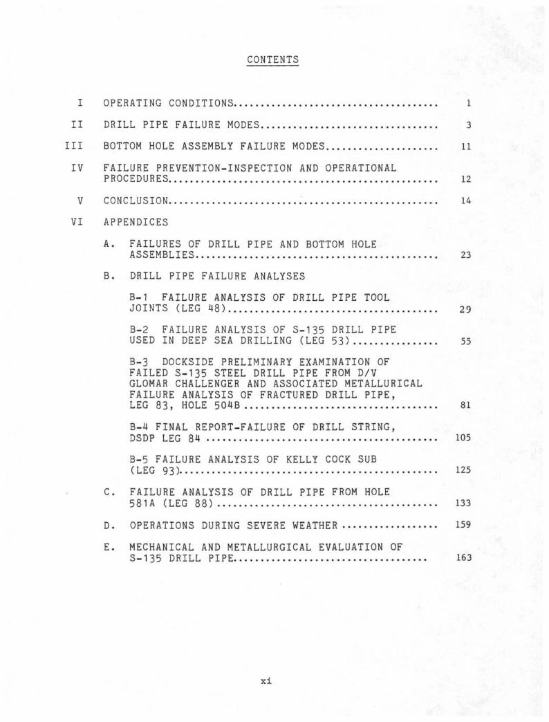
CONTENTS
I OPERATING CONDITIONS 1
II DRILL PIPE FAILURE MODES 3
III BOTTOM HOLE ASSEMBLY FAILURE MODES 11
IV FAILURE PREVENTION-INSPECTION AND OPERATIONAL
PROCEDURES 12
V CONCLUSION 14
VI APPENDICESA. FAILURES OF DRILL PIPE AND BOTTOM HOLE
ASSEMBLIES 23
B. DRILL PIPE FAILURE ANALYSES
B-1 FAILURE ANALYSIS OF DRILL PIPE TOOLJOINTS (LEG 48) 29
B-2 FAILURE ANALYSIS OF S-135 DRILL PIPEUSED IN DEEP SEA DRILLING (LEG 53) 55
B-3 DOCKSIDE PRELIMINARY EXAMINATION OFFAILED S-135 STEEL DRILL PIPE FROM D/VGLOMAR CHALLENGER AND ASSOCIATED METALLURICALFAILURE ANALYSIS OF FRACTURED DRILL PIPE,LEG 83, HOLE 504B 81
B-4 FINAL REPORT-FAILURE OF DRILL STRING,DSDP LEG 84 105
B-5 FAILURE ANALYSIS OF KELLY COCK SUB(LEG 93) 125
C. FAILURE ANALYSIS OF DRILL PIPE FROM HOLE
581A (LEG 88) 133
D. OPERATIONS DURING SEVERE WEATHER 159
E. MECHANICAL AND METALLURGICAL EVALUATION OFS-135 DRILL PIPE 163
x i
LIST OF FIGURES
1. Configuration of Drill String
2. Bending Stress in Drill Pipe
3. Corrosion on Interior Surface of Drill Pipe
4. Typical Bottom Hole Assembly (BHA)
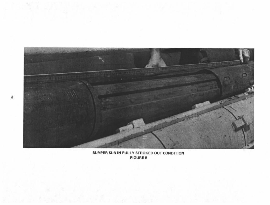
5. Bumper Sub in Fully Stroked Out Condition
LIST OF TABLES
I. Properties of S-135 Steel
xiii
I. OPERATING CONDITIONS
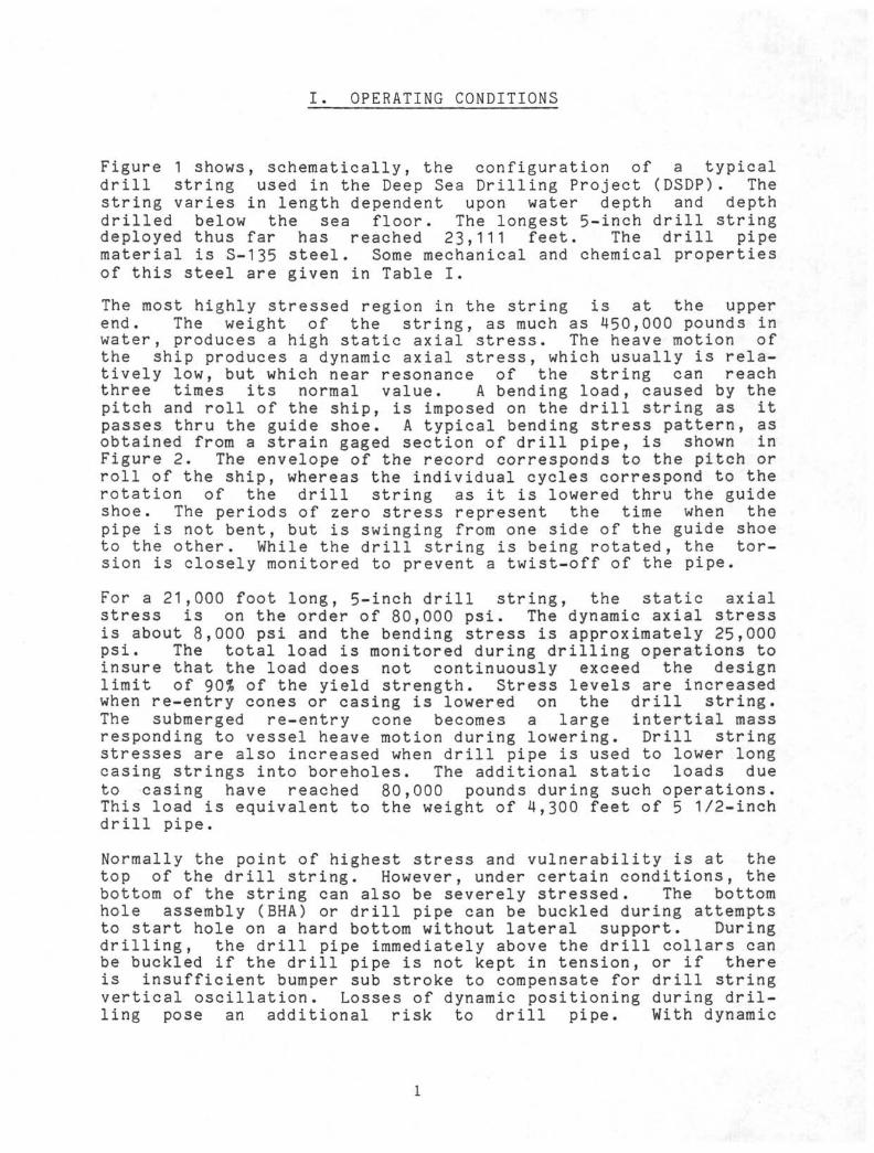
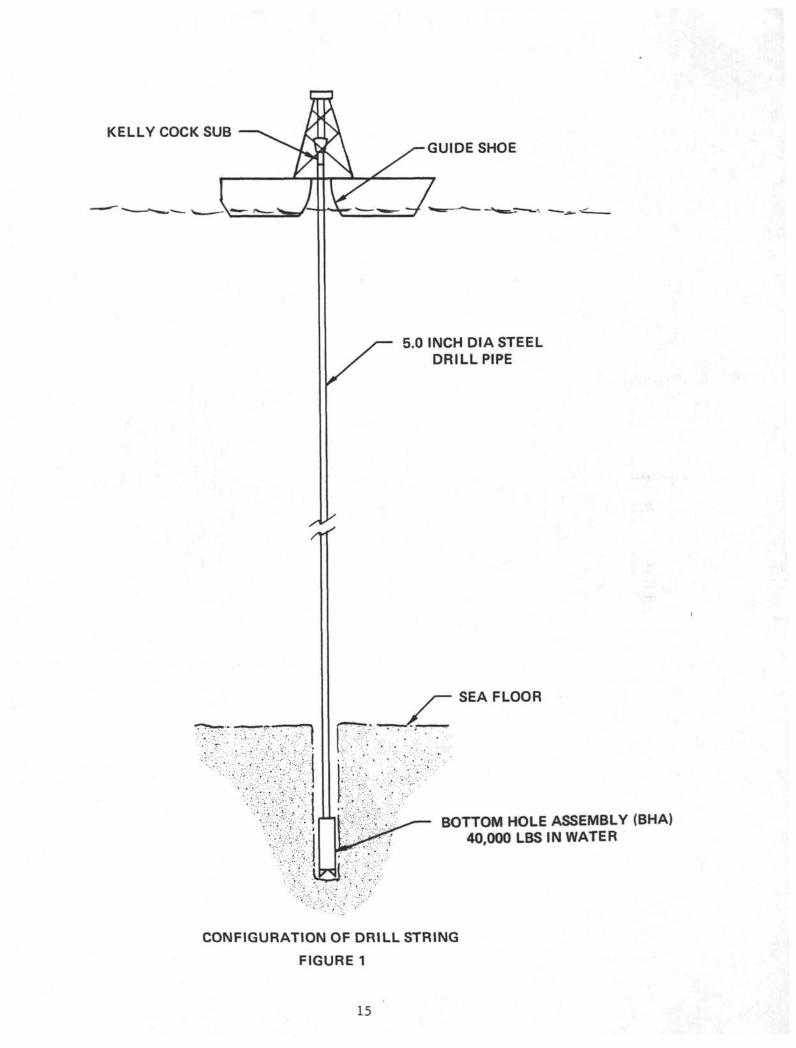
Figure 1 shows, schematically, the configuration of a typicaldrill string used in the Deep Sea Drilling Project (DSDP). Thestring varies in length dependent upon water depth and depthdrilled below the sea floor. The longest 5-inch drill stringdeployed thus far has reached 23,111 feet. The drill pipematerial is S-135 steel. Some mechanical and chemical propertiesof this steel are given in Table I.
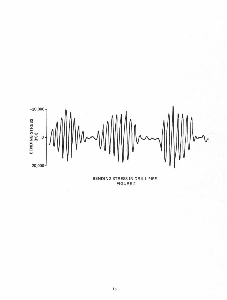
The most highly stressed region in the string is at the upperend. The weight of the string, as much as 450,000 pounds inwater, produces a high static axial stress. The heave motion ofthe ship produces a dynamic axial stress, which usually is rela-tively low, but which near resonance of the string can reachthree times its normal value. A bending load, caused by thepitch and roll of the ship, is imposed on the drill string as itpasses thru the guide shoe. A typical bending stress pattern, asobtained from a strain gaged section of drill pipe, is shown inFigure 2. The envelope of the record corresponds to the pitch orroll of the ship, whereas the individual cycles correspond to therotation of the drill string as it is lowered thru the guideshoe. The periods of zero stress represent the time when thepipe is not bent, but is swinging from one side of the guide shoeto the other. While the drill string is being rotated, the tor-sion is closely monitored to prevent a twist-off of the pipe.
For a 21,000 foot long, 5-inch drill string, the static axialstress is on the order of 80,000 psi. The dynamic axial stressis about 8,000 psi and the bending stress is approximately 25,000psi. The total load is monitored during drilling operations toinsure that the load does not continuously exceed the designlimit of 90% of the yield strength. Stress levels are increasedwhen re-entry cones or casing is lowered on the drill string.The submerged re-entry cone becomes a large intertial massresponding to vessel heave motion during lowering. Drill stringstresses are also increased when drill pipe is used to lower longcasing strings into boreholes. The additional static loads dueto casing have reached 80,000 pounds during such operations.This load is equivalent to the weight of 4,300 feet of 5 1/2-inchdrill pipe.
Normally the point of highest stress and vulnerability is at thetop of the drill string. However, under certain conditions, thebottom of the string can also be severely stressed. The bottomhole assembly (BHA) or drill pipe can be buckled during attemptsto start hole on a hard bottom without lateral support. Duringdrilling, the drill pipe immediately above the drill collars canbe buckled if the drill pipe is not kept in tension, or if thereis insufficient bumper sub stroke to compensate for drill stringvertical oscillation. Losses of dynamic positioning during dril-ling pose an additional risk to drill pipe. With dynamic
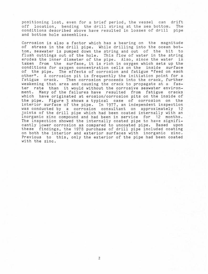
positioning lost, even for a brief period, the vessel can driftoff location, bending the drill string at the sea bottom. Theconditions described above have resulted in losses of drill pipeand bottom hole assemblies.
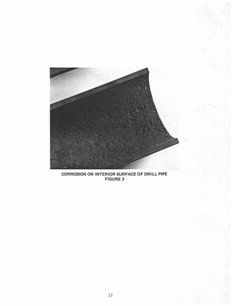
Corrosion is also a factor which has a bearing on the magnitudeof stress in the drill pipe. While drilling into the ocean bot-tom, seawater is pumped down the string and out of the bit toflush cuttings out of the hole. This flow of water in the stringerodes the inner diameter of the pipe. Also, since the water istaken from the surface, it is rich in oxygen which sets up theconditions for oxygen concentration cells on the inside surfaceof the pipe. The effects of corrosion and fatigue "feed on eachother". A corrosion pit is frequently the initiation point for afatigue crack. Then corrosion proceeds into the crack, furtherweakening that area and causing the crack to propagate at a fas-ter rate than it would without the corrosive seawater environ-ment. Many of the failures have resulted from fatigue crackswhich have originated at erosion/corrosion pits on the inside ofthe pipe. Figure 3 shows a typical case of corrosion on theinterior surface of the pipe. In 1977, an independent inspectionwas conducted by a corrosion consultant on approximately 12joints of the drill pipe which had been coated internally with aninorganic zinc compound and had been in service for 12 months.The inspection showed the internally coated pipe to have signifi-cantly lower corrosion as compared to uncoated pipe. Based uponthese findings, the 1978 purchase of drill pipe included coatingon both the interior and exterior surfaces with inorganic zinc.Previous to this, only the exterior of the pipe had been coatedwith the zinc.
II DRILL PIPE FAILURE MODES
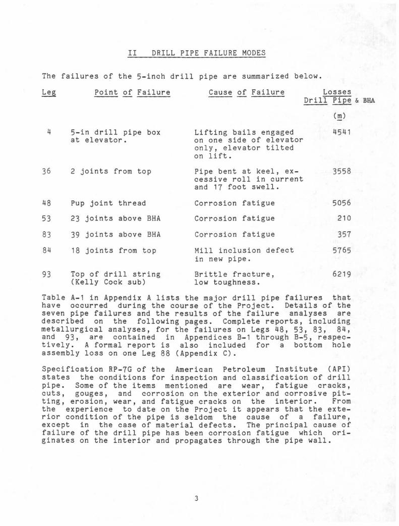
The failures of the 5-inch drill pipe are summarized below.
Leg Point _of Failure Cause of Failure LossesDrill Pipe & BHA
Cm)
36
5-in drill pipe boxat elevator.
2 joints from top
48 Pup joint thread
53 23 joints above BHA
83 39 joints above BHA
84 18 joints from top
93 Top of drill string(Kelly Cock sub)
Lifting bails engagedon one side of elevatoronly, elevator tiltedon lift.
Pipe bent at keel, ex-cessive roll in currentand 17 foot swell.
Corrosion fatigue
Corrosion fatigue
Corrosion fatigue
Mill inclusion defectin new pipe.
Brittle fracture,low toughness.
4541
3558
5056
210
357
5765
6219
Table A-1 in Appendix A lists the major drill pipe failures thathave occurred during the course of the Project. Details of theseven pipe failures and the results of the failure analyses aredescribed on the following pages. Complete reports, includingmetallurgical analyses, for the failures on Legs 48, 53, 83, 84,and 93, are contained in Appendices B-1 through B-5, respec-tively. A formal report is also included for a bottom holeassembly loss on one Leg 88 (Appendix C).
Specification RP-7G of the American Petroleum Institute (API)states the conditions for inspection and classification of drillpipe. Some of the items mentioned are wear, fatigue cracks,cuts, gouges, and corrosion on the exterior and corrosive pit-ting, erosion, wear, and fatigue cracks on the interior. Fromthe experience to date on the Project it appears that the exte-rior condition of the pipe is seldom the cause of a failure,except in the case of material defects. The principal cause offailure of the drill pipe has been corrosion fatigue which ori-ginates on the interior and propagates through the pipe wall.
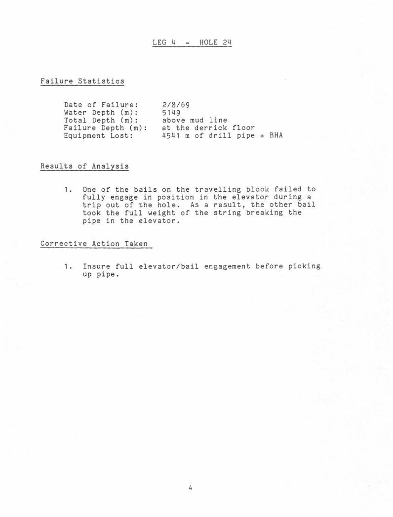
Failure Statistics
LEG 4 - HOLE 24
Date of FailureWater Depth (m)Total Depth (m)Failure Depth (m)Equipment Lost:
2/8/695149above mud lineat the derrick floor4541 m of drill pipe + BHA
Results of Analysis
1. One of the bails on the travelling block failed tofully engage in position in the elevator during atrip out of the hole. As a result, the other bailtook the full weight of the string breaking thepipe in the elevator.
Corrective Action Taken
1. Insure full elevator/bail engagement before pickingup pipe.
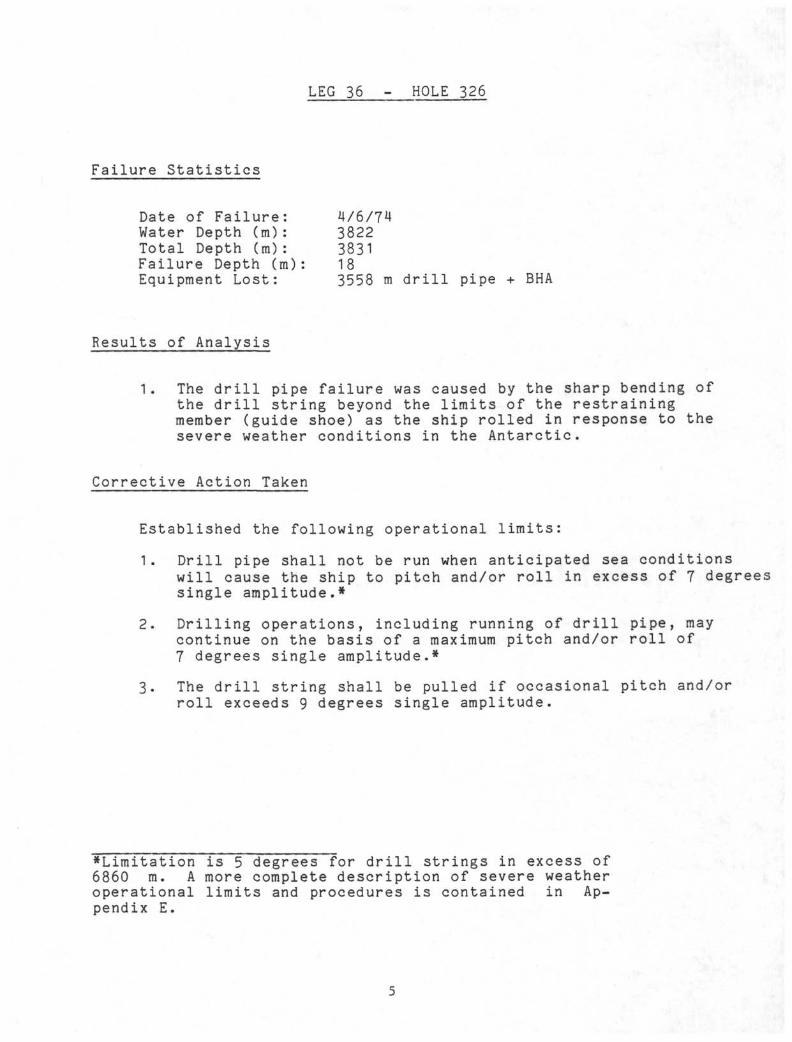
LEG 36 - HOLE 326
Failure Statistics
Date of Failure: 4/6/74Water Depth (m): 3822Total Depth (m): 3831Failure Depth (m): 18Equipment Lost: 3558 m drill pipe + BHA
Results of Analysis
1. The drill pipe failure was caused by the sharp bending ofthe drill string beyond the limits of the restrainingmember (guide shoe) as the ship rolled in response to thesevere weather conditions in the Antarctic.
Corrective Action Taken
Established the following operational limits:
1. Drill pipe shall not be run when anticipated sea conditionswill cause the ship to pitch and/or roll in excess of 7 degreessingle amplitude.*
2. Drilling operations, including running of drill pipe, maycontinue on the basis of a maximum pitch and/or roll of7 degrees single amplitude.*
3. The drill string shall be pulled if occasional pitch and/orroll exceeds 9 degrees single amplitude.
*Limitation is 5 degrees for drill strings in excess of6860 m. A more complete description of severe weatheroperational limits and procedures is contained in Ap-pendix E.
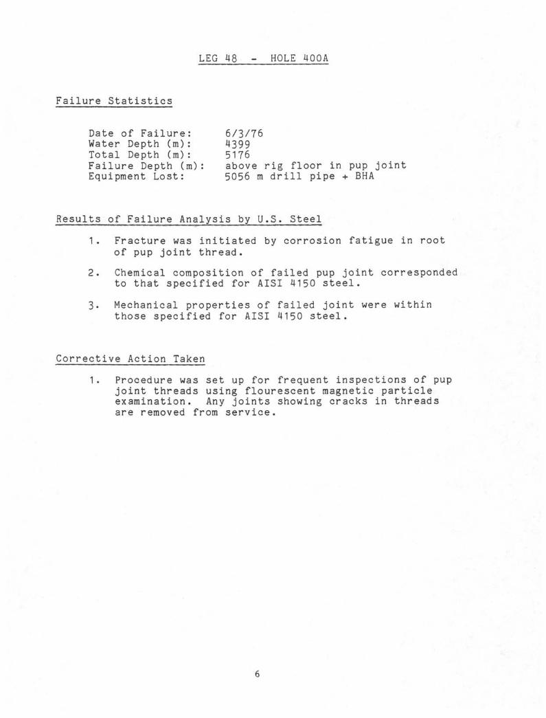
LEG 48 - HOLE 400A
Failure Statistics
Date of Failure: 6/3/76Water Depth (m): 4399Total Depth (m): 5176Failure Depth (m): above rig floor in pup jointEquipment Lost: 5056 m drill pipe + BHA
Results of Failure Analysis by U.S. Steel
1. Fracture was initiated by corrosion fatigue in rootof pup joint thread.
2. Chemical composition of failed pup joint correspondedto that specified for AISI 4150 steel.
3. Mechanical properties of failed joint were withinthose specified for AISI 4150 steel.
Corrective Action Taken
1. Procedure was set up for frequent inspections of pupjoint threads using flourescent magnetic particleexamination. Any joints showing cracks in threadsare removed from service.
LEG 53 - HOLE 418A
Failure Statistics
Date of Failure: 4/6/77Water Depth (m): 5519Total Depth (m): 5816Failure Depth (m): 5519Equipment Lost: 210 m drill pipe + BHA
Results of Failure Analysis by U. S. Steel
1. Fracture was result of corrosion fatigue initiatedon external surface of pipe.
2. Chemical composition of failed pipe corresponded tothat given in API Specification 5AX.
3. Mechanical properties of failed pipe were within thosegiven in API Specification 5AX.
Corrective Action Taken
1. A policy was established whereby only premium classdrill pipe was to be used . in any further drillingoperations. The Project has followed this policy.
2. The interval for periodic inspection of the drill pipewas set at 4 to 6 months.
LEG 83 - HOLE 504B
Failure StatisticsDate of Failure: 11/29/81Water Depth (m): 3473Total Depth (m): 4535, 4763Failure Depth (m): 4033, 4543Equipment Lost: 357 m drill pipe + BHA (first failure)
100 m drill pipe + BHA (second failure)
Results of Failure Analysis by Battelle
1. Failure was due to corrosion fatigue.
2. Fatigue cracks originated at deep broad corrosion pitson inside surface of pipe.
3. Mechanical properties of drill pipe met API Specification 5AX
4. Chemical composition of drill pipe met API Specification 5AX.
5. Basic cause of failures was inability of internal inspectionsystem to detect advanced corrosion damage on interiorsurface of drill pipe.
Corrective Action Taken
1. All suspect pipe (588 joints) was removed from ship andinspected by External Sonoscope and ultrasonic wallthickness measuring instruments.
LEG 84 - HOLE 567A
Failure Statistics
Date of FailureWater Depth (m)Total Depth (m)
2/7/8255296030
Failure Depth (m): 165Equipment Lost: 5765 m drill pipe + BHA
Results of Failure Analysis by Battelle
1. Lap defect, at fracture point, probably produced duringtube rolling operation, and which was rejectableaccording to API Specification 5AX.
2. Yield strength of 170,800 psi was higher than that allowed(165,000 psi) in API Specification 5AX.
3. Hydrogen embrittlement was contributing factor in failure,especially since yield strength was higher than allowed.
Corrective Action Taken
1. Hardness of Re 38.5 corresponds to yield strength of165,000 psi. Joints of pipe with hardness in excessof Re 38 were removed from service.
LEG 93 - HOLE 6O3B
Failure Statistics
Date of Failure:Water of Depth (m)Total Depth (m):Failure Depth (m):Equipment Lost:
6/1/8346446229at rig6219 m
floordrill pipe + BHA
Results of Failure Analysis by Battelle
1. Kelly Cock sub failed by brittle fracture initiated atfatigue cracks which began at corrosion pits in theroot of the last engaged thread.
2. Thoughness of Kelly Cock sub was low due to presence ofmixed microstructure.
Corrective Action Taken
1. Recommendation from Battelle is to specify a toughermaterial such as quenched and tempered 4340 steel forreplacement subs. Also, there should be a programmedreplacement of the sub, say every five years.
10
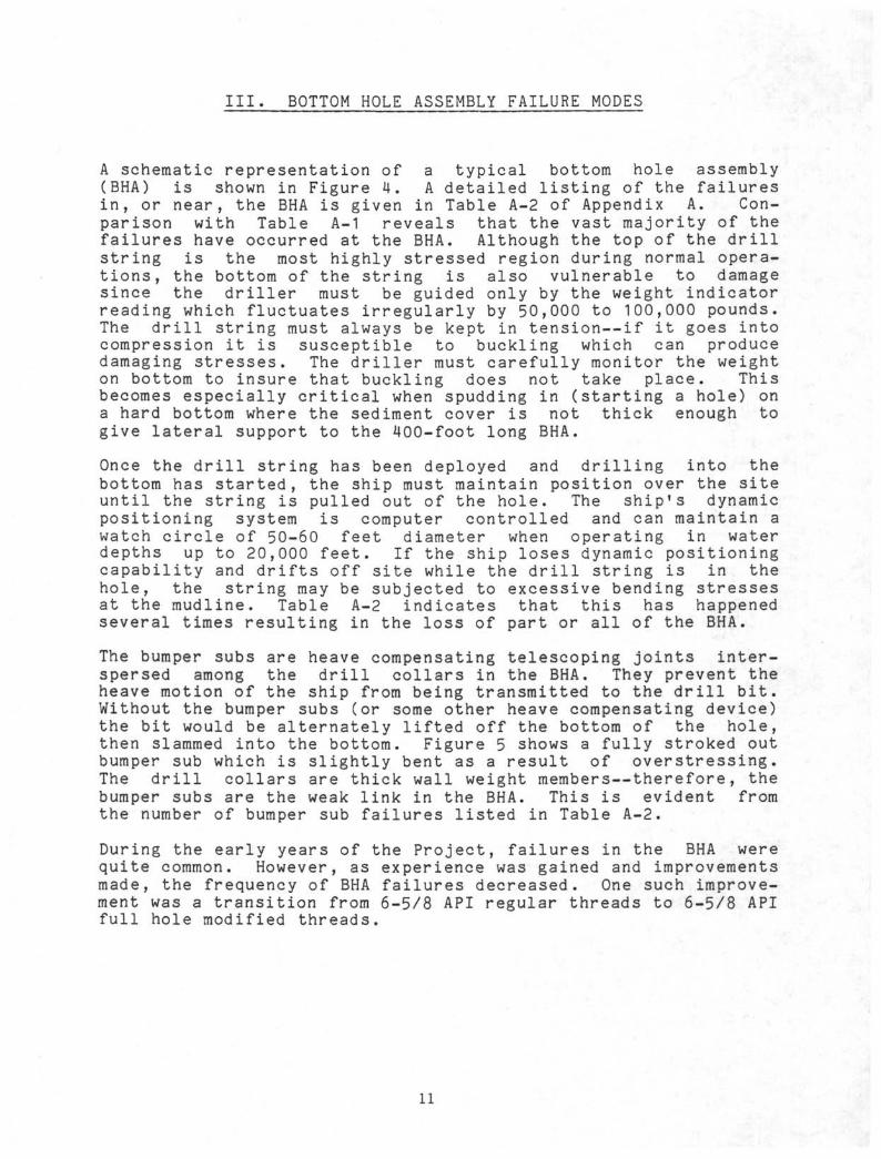
III. BOTTOM HOLE ASSEMBLY FAILURE MODES
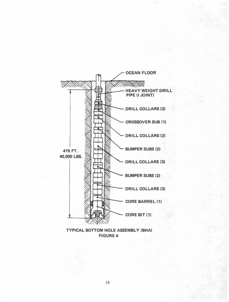
A schematic representation of a typical bottom hole assembly(BHA) is shown in Figure 4. A detailed listing of the failuresin, or near, the BHA is given in Table A-2 of Appendix A. Con-parison with Table A-1 reveals that the vast majority of thefailures have occurred at the BHA. Although the top of the drillstring is the most highly stressed region during normal opera-tions, the bottom of the string is also vulnerable to damagesince the driller must be guided only by the weight indicatorreading which fluctuates irregularly by 50,000 to 100,000 pounds.The drill string must always be kept in tension—if it goes intocompression it is susceptible to buckling which can producedamaging stresses. The driller must carefully monitor the weighton bottom to insure that buckling does not take place. Thisbecomes especially critical when spudding in (starting a hole) ona hard bottom where the sediment cover is not thick enough togive lateral support to the 400-foot long BHA.
Once the drill string has been deployed and drilling into thebottom has started, the ship must maintain position over the siteuntil the string is pulled out of the hole. The ship's dynamicpositioning system is computer controlled and can maintain awatch circle of 50-60 feet diameter when operating in waterdepths up to 20,000 feet. If the ship loses dynamic positioningcapability and drifts off site while the drill string is in thehole, the string may be subjected to excessive bending stressesat the mudline. Table A-2 indicates that this has happenedseveral times resulting in the loss of part or all of the BHA.
The bumper subs are heave compensating telescoping joints inter-spersed among the drill collars in the BHA. They prevent theheave motion of the ship from being transmitted to the drill bit.Without the bumper subs (or some other heave compensating device)the bit would be alternately lifted off the bottom of the hole,then slammed into the bottom. Figure 5 shows a fully stroked outbumper sub which is slightly bent as a result of overstressing.The drill collars are thick wall weight members—therefore, thebumper subs are the weak link in the BHA. This is evident fromthe number of bumper sub failures listed in Table A-2.
During the early years of the Project, failures in the BHA werequite common. However, as experience was gained and improvementsmade, the frequency of BHA failures decreased. One such improve-ment was a transition from 6-5/8 API regular threads to 6-5/8 APIfull hole modified threads.
11
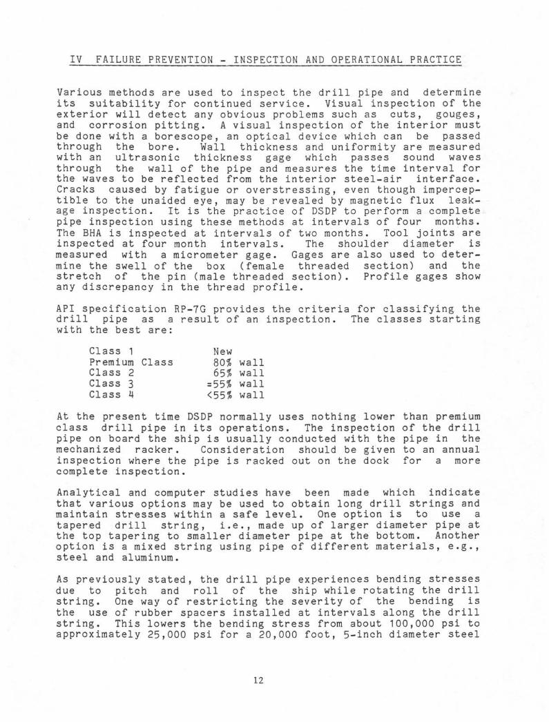
IV FAILURE PREVENTION - INSPECTION AND OPERATIONAL PRACTICE
Various methods are used to inspect the drill pipe and determineits suitability for continued service. Visual inspection of theexterior will detect any obvious problems such as cuts, gouges,and corrosion pitting. A visual inspection of the interior mustbe done with a borescope, an optical device which can be passedthrough the bore. Wall thickness and uniformity are measuredwith an ultrasonic thickness gage which passes sound wavesthrough the wall of the pipe and measures the time interval forthe waves to be reflected from the interior steel-air interface.Cracks caused by fatigue or overstressing, even though impercep-tible to the unaided eye, may be revealed by magnetic flux leak-age inspection. It is the practice of DSDP to perform a completepipe inspection using these methods at intervals of four months.The BHA is inspected at intervals of two months. Tool joints areinspected at four month intervals. The shoulder diameter ismeasured with a micrometer gage. Gages are also used to deter-mine the swell of the box (female threaded section) and thestretch of the pin (male threaded section). Profile gages showany discrepancy in the thread profile.
API specification RP-7G provides the criteria for classifying thedrill pipe as a result of an inspection. The classes startingwith the best are:
Class 1 NewPremium Class 80% wallClass 2 65% wallClass 3 = 55% wallClass 4 <55% wall
At the present time DSDP normally uses nothing lower than premiumclass drill pipe in its operations. The inspection of the drillpipe on board the ship is usually conducted with the pipe in themechanized racker. Consideration should be given to an annualinspection where the pipe is racked out on the dock for a morecomplete inspection.
Analytical and computer studies have been made which indicatethat various options may be used to obtain long drill strings andmaintain stresses within a safe level. One option is to use atapered drill string, i.e., made up of larger diameter pipe atthe top tapering to smaller diameter pipe at the bottom. Anotheroption is a mixed string using pipe of different materials, e.g.,steel and aluminum.
As previously stated, the drill pipe experiences bending stressesdue to pitch and roll of the ship while rotating the drillstring. One way of restricting the severity of the bending isthe use of rubber spacers installed at intervals along the drillstring. This lowers the bending stress from about 100,000 psi toapproximately 25,000 psi for a 20,000 foot, 5-inch diameter steel
12
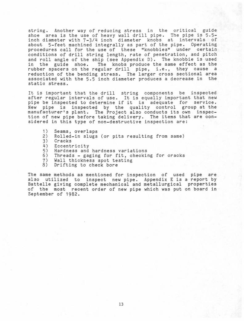
string. Another way of reducing stress in the critical guideshoe area is the use of heavy wall drill pipe. The pipe is 5.5-inch diameter with 7-3/4 inch diameter knobs at intervals ofabout 5-feet machined integrally as part of the pipe. Operatingprocedures call for the use of these "knobbies" under certainconditions of drill string length, rate of penetration, and pitchand roll angle of the ship (see Appendix D). The knobbie is usedin the guide shoe. The knobs produce the same effect as therubber spacers on the regular drill pipe, i.e., they cause areduction of the bending stress. The larger cross sectional areaassociated with the 5.5 inch diameter produces a decrease in thestatic stress.
It is important that the drill string components be inspectedafter regular intervals of use. It is equally important that newpipe be inspected to determine if it is adequate for service.New pipe is inspected by the quality control group at themanufacturers plant. The Project also conducts its own inspec-tion of new pipe before taking delivery. The items that are con-sidered in this type of non-destructive inspection are:
1) Seams, overlaps2) Rolled-in slugs (or pits resulting from same)3) Cracks4) Eccentricity5) Hardness and hardness variations6) Threads - gaging for fit, checking for cracks7) Wall thickness spot testing8) Drifting to check bore
The same methods as mentioned for inspection of used pipe arealso utilized to inspect new pipe. Appendix E is a report byBattelle giving complete mechanical and metallurgical propertiesof the most recent order of new pipe which was put on board inSeptember of 1982.
13
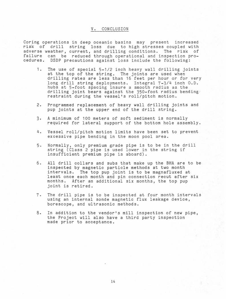
V. CONCLUSION
Coring operations in deep oceanic basins may present increasedrisk of drill string loss due to high stresses coupled withadverse weather, current, and drilling conditions. The risk offailure can be reduced through operational and inspection pro-cedures. DSDP precautions against loss include the following:
1. The use of special 5-1/2 inch heavy wall drilling jointsat the top of the string. The joints are used whendrilling rates are less than 16 feet per hour or for verylong drill string deployments. Integral 7-3/4 inch O.D.hubs at 5-foot spacing insure a smooth radius as thedrilling joint bears against the 350-foot radius bendingrestraint during the vessel s roll/pitch motion.
2. Programmed replacement of heavy wall drilling joints andpup joints at the upper end of the drill string.
3. A minimum of 100 meters of soft sediment is normallyrequired for lateral support of the bottom hole assembly.
4. Vessel roll/pitch motion limits have been set to preventexcessive pipe bending in the moon pool area.
5. Normally, only premium grade pipe is to be in the drillstring (Class 2 pipe is used lower in the string ifinsufficient premium pipe is aboard) .
6. All drill collars and subs that make up the BHA are to beinspected by magnetic particle methods at two monthintervals. The top pup joint is to be magnafluxed atleast once each month and pin connection recut after sixmonths. After an additional six months, the top pupjoint is retired.
7. The drill pipe is to be inspected at four month intervalsusing an internal sonde magnetic flux leakage device,borescope, and ultrasonic methods.
8. In addition to the vendor's mill inspection of new pipe,the Project will also have a third party inspectionmade prior to acceptance.
14
KELLY COCK SUBGUIDE SHOE
5.0 INCH DIA STEELDRILL PIPE
SEA FLOOR
BOTTOM HOLE ASSEMBLY (BHA)40,000 LBS IN WATER
CONFIGURATION OF DRILL STRING
FIGURE 1
15
* 20,000-
8αiccC/5 --;.
O<g5LLJCO
0 -
•20,000J
BENDING STRESS IN DRILL PIPEFIGURE 2
16
CORROSION ON INTERIOR SURFACE OF DRILL PIPEFIGURE 3
17
OCEAN FLOOR
HEAVY WEIGHT DRILLPIPE (I JOINT)
DRILL COLLARS (2)
CROSSOVER SUB (1)
DRILL COLLARS (2)
BUMPER SUBS (2)
DRILL COLLARS (3)
BUMPER SUBS (2)
DRILL COLLARS (3)
CORE BARREL (1)
CORE BIT (1)
TYPICAL BOTTOM HOLE ASSEMBLY (BHA)FIGURE 4
19
hoO
BUMPER SUB IN FULLY STROKED OUT CONDITIONFIGURE 5
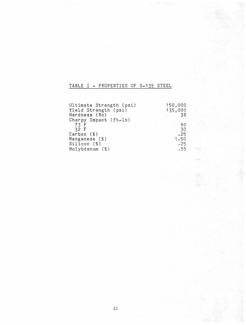
TABLE I - PROPERTIES OF S-135 STEEL
Ultimate Strength (psi)Yield Strength (psi)Hardness (Re)Charpy Impact (ft-lb)73 F32 F
Carbon (%)Manganese {%)Silicon (%)Molybdenum (%) .55
150,135,
1
000000
38
4030
.25
.50
.25
•
21
APPENDIX A
FAILURES OF DRILL PIPE AND BOTTOM HOLE ASSEMBLIES
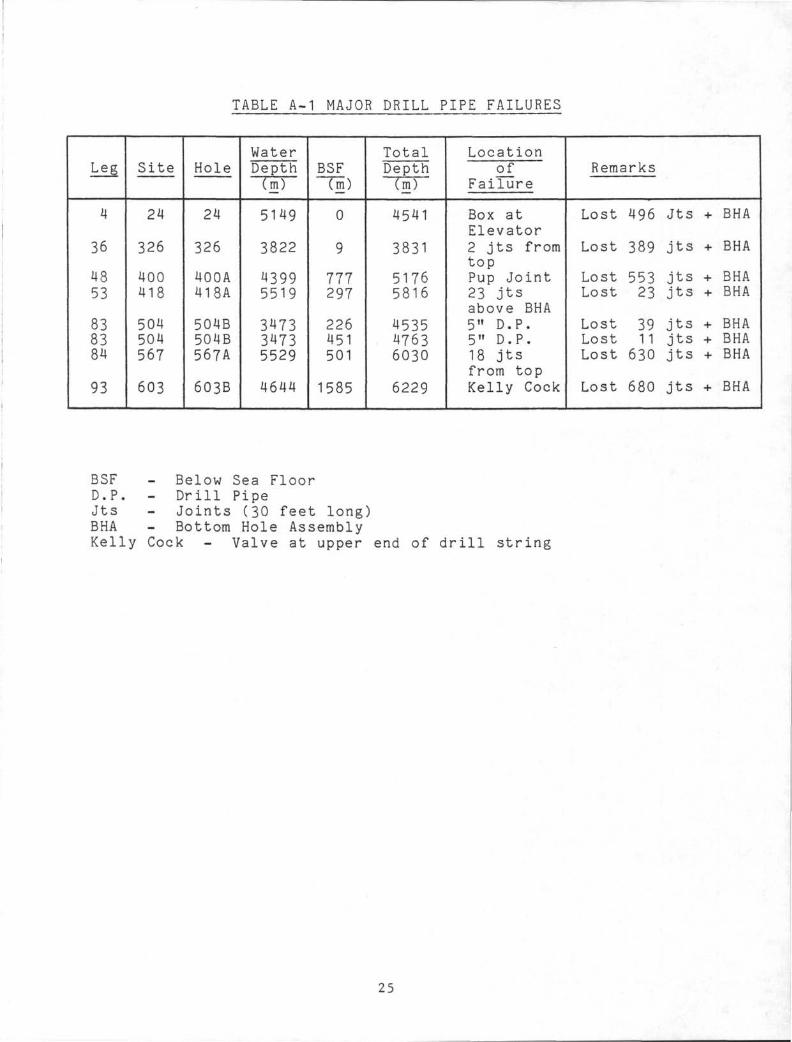
TABLE A-1 MAJOR DRILL PIPE FAILURES
J-" c O
4
36
4853
838384
93
Site
24
326
400418
504504567
603
Hole
24
326
400A418A
504B504B567A
6O3B
WaterDepthCm)
5149
3822
43995519
347334735529
4644
BSF(m)
0
9
111297
226451501
1585
TotalDepthCm)
4541
3831
51765816
453547636030
6229
Locationof
Failure
Box atElevator2 jts fromtopPup Joint23 jtsabove BHA5" D.P.5" D.P.18 jtsfrom topKelly Cock
Remarks
Lost 496 Jts + BHA
Lost 389 jts + BHA
Lost 553 jts + BHALost 23 jts + BHA
Lost 39 jts + BHALost 11 jts + BHALost 630 jts + BHA
Lost 680 jts + BHA
BSF - Below Sea FloorD.P. - Drill PipeJts - Joints (30 feet long)BHA - Bottom Hole AssemblyKelly Cock - Valve at upper end of drill strini
25
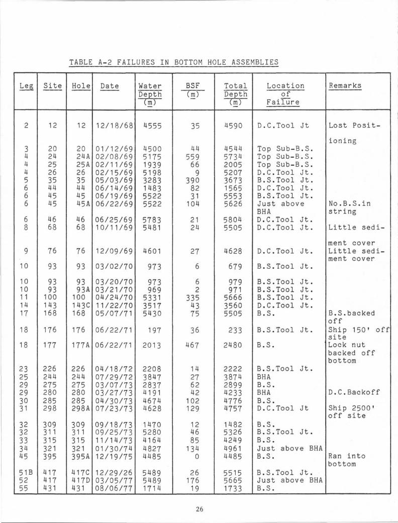
TABLE A-2 FAILURES IN BOTTOM HOLE ASSEMBLIES
Leg
2
34445666
68
9
10
10101 11417
18
18
232529293031
3232333445
51B5255
Site
12
2024252635444545
4668
76
93
9393100143168
176
177
226244275280285298
309311315321395
417417431
Hole
12
2024A25A2635444545A
4668
76
93
9393A100143C168
176
177A
226244275280285298A
309311315321395A
417C417D431
Date
12/18/68
01/12/6902/08/6902/11/6902/15/6905/03/6906/14/6906/19/6906/22/69
06/25/6910/11/69
12/09/69
03/02/70
03/20/7003/21/7004/24/7011/22/7005/07/71
06/22/71
06/22/71
04/18/7207/29/7203/07/7303/27/7304/30/7307/23/73
09/18/7309/25/7311/14/7301/30/7412/19/75
12/29/2603/05/7708/06/77
WaterDepth
"TmT
4555
45005175193951983283148355225522
57835481
4601
973
973969533135175430
197
2013
220838472837419146744628
14705280416448274485
548954891714
BSFCm)
35
44559669
3908231104
2124
27
6
62
3354375
36
467
14276242102129
1246851340
2617619
TotalDepth(m)
4590
45445734200552073673156555535626
58045505
4628
679
979971566635605505
233
2480
222238742899423347764757
14825326424949614485
551556651733
Locationof
Failure
D.C.Tool Jt
Top Sub-B.S.Top Sub-B.S.Top Sub-B.S.D.C.Tool Jt.B.S.Tool Jt.D.C.Tool Jt.B.S.Tool Jt.Just aboveBHAD.C.Tool Jt.D.C.Tool Jt.
D.C.Tool Jt.
B.S.Tool Jt.
B.S.Tool Jt.B.S.Tool Jt.B.S.Tool Jt.D.C.Tool Jt.B.S.
B.S.Tool Jt.
B.S.
B.S.Tool Jt.BHAB.S.BHAB.S.D.C.Tool Jt
B.S.B.S.Tool Jt.B.S.Just above BHAB.S.
B.S.Tool Jt.Just above BHAB.S.
Remarks
Lost Posit-
ioning
No.B.S.instring
Little sedi-
ment coverLittle sedi-ment cover
B.S.backedoffShip 150 f offsiteLock nutbacked offbottom
D.C.Backoff
Ship 2500'off site
Ran intobottom
26
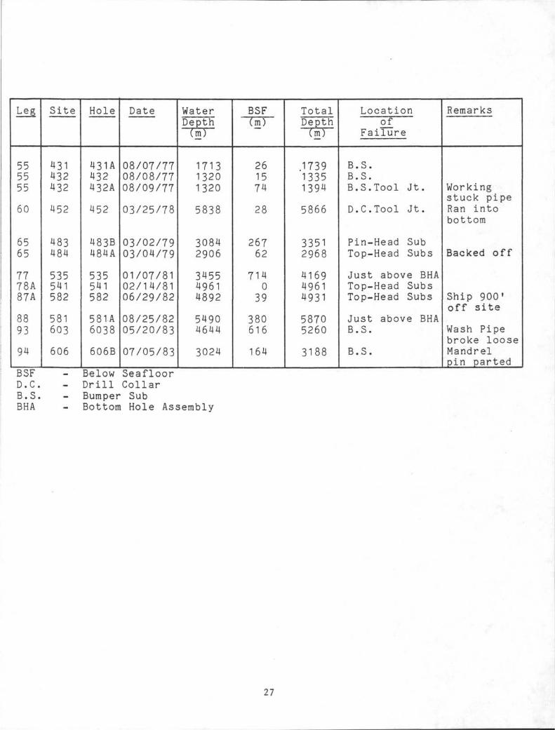
Leg
555555
60
6565
7778A87A
8893
94
Site
431432432
452
483484
535541582
581603
606
Hole
431A432432A
452
483B484A
535541582
581A6038
606B
Date
08/07/7708/08/7708/09/77
03/25/78
03/02/7903/04/79
01/07/8102/14/8106/29/82
08/25/8205/20/83
07/05/83
WaterDepth
~TmT"
171313201320
5838
30842906
345549614892
54904644
3024
BSF(m)
261574
28
26762
714039
380616
164
TotalDepth( m )
173913351394
5866
33512968
416949614931
58705260
3188
Locationof
Failure
B.S.B.S.B.S.Tool Jt.
D.C.Tool Jt.
Pin-Head SubTop-Head Subs
Just above BHATop-Head SubsTop-Head Subs
Just above BHAB.S.
B.S.
Remarks
Workingstuck pipeRan intobottom
Backed off
Ship 900f
off site
Wash Pipebroke looseMandrelpin parted
BSFD.CB.SBHA
Below SeafloorDrill CollarBumper SubBottom Hole Assembly
27
APPENDIX B-1
FAILURE ANALYSIS OFDRILL PIPE TOOL JOINTS
(LEG 48)
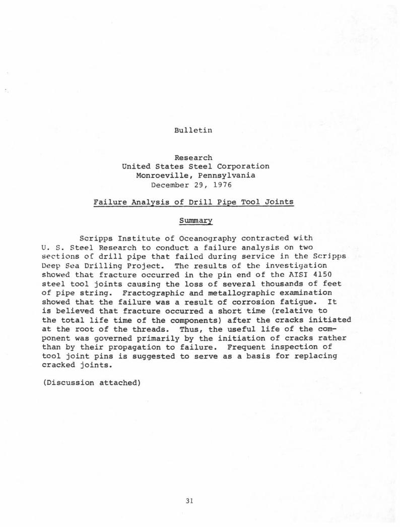
Bulletin
ResearchUnited States Steel Corporation
Monroeville, PennsylvaniaDecember 29, 1976
Failure Analysis of Drill Pipe Tool Joints
Summary
Scripps Institute of Oceanography contracted withU. S. Steel Research to conduct a failure analysis on twosections of drill pipe that failed during service in the ScrippsDeep Sea Drilling Project. The results of the investigationshowed that fracture occurred in the pin end of the AISI 4150steel tool joints causing the loss of several thousands of feetof pipe string. Fractographic and metallographic examinationshowed that the failure was a result of corrosion fatigue. Itis believed that fracture occurred a short time (relative tothe total life time of the components) after the cracks initiatedat the root of the threads. Thus, the useful life of the com-ponent was governed primarily by the initiation of cracks ratherthan by their propagation to failure. Frequent inspection oftool joint pins is suggested to serve as a basis for replacingcracked joints.
(Discussion attached)
31
FAILURE ANALYSIS OF
DRILL PIPE TOOL JOINTS December 29, 1976
Discussion
Introduction
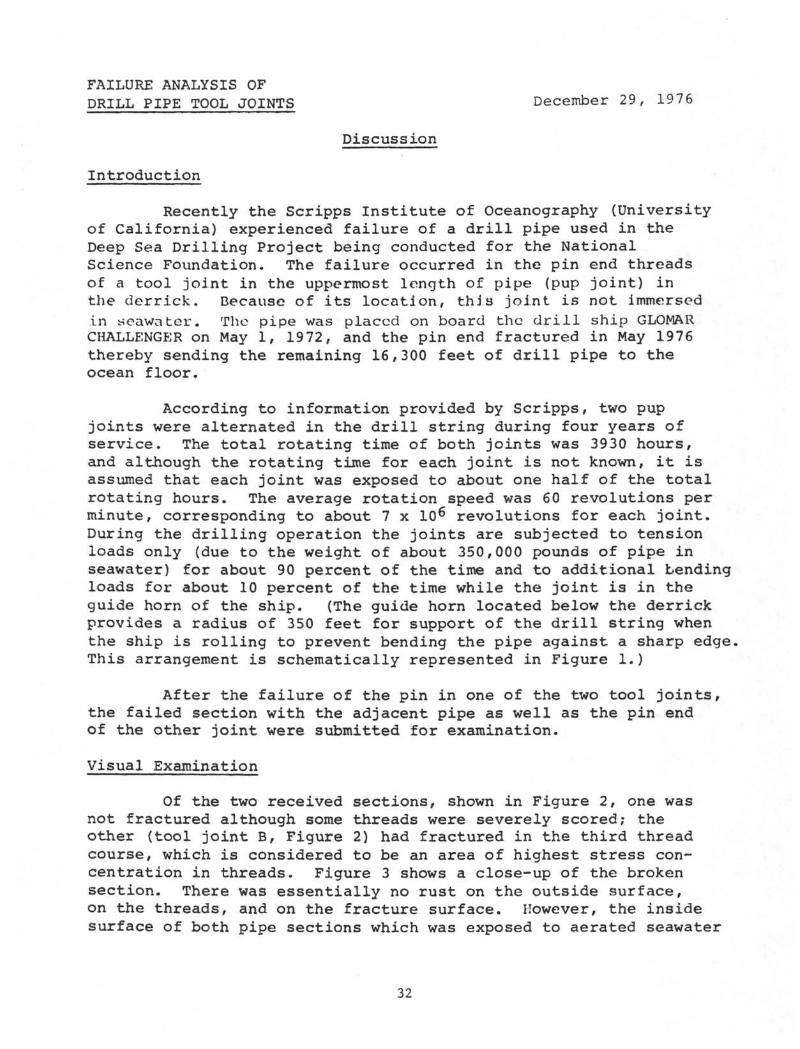
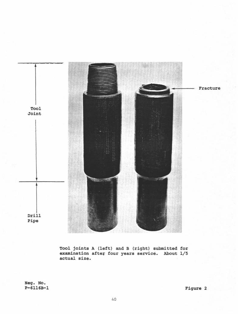
Recently the Scripps Institute of Oceanography (Universityof California) experienced failure of a drill pipe used in theDeep Sea Drilling Project being conducted for the NationalScience Foundation. The failure occurred in the pin end threadsof a tool joint in the uppermost length of pipe (pup joint) inthe derrick. Because of its location, this joint is not immersedin seawater. The pipe was placed on board the drill ship GLOMARCHALLENGER on May 1, 1972, and the pin end fractured in May 1976thereby sending the remaining 16,300 feet of drill pipe to theocean floor.
According to information provided by Scripps, two pupjoints were alternated in the drill string during four years ofservice. The total rotating time of both joints was 3930 hours,and although the rotating time for each joint is not known, it isassumed that each joint was exposed to about one half of the totalrotating hours. The average rotation speed was 60 revolutions perminute, corresponding to about 7 x 10^ revolutions for each joint.During the drilling operation the joints are subjected to tensionloads only (due to the weight of about 350,000 pounds of pipe inseawater) for about 90 percent of the time and to additional bendingloads for about 10 percent of the time while the joint is in theguide horn of the ship. (The guide horn located below the derrickprovides a radius of 350 feet for support of the drill string whenthe ship is rolling to prevent bending the pipe against a sharp edgeThis arrangement is schematically represented in Figure 1.)
After the failure of the pin in one of the two tool joints,the failed section with the adjacent pipe as well as the pin endof the other joint were submitted for examination.
Visual Examination
Of the two received sections, shown in Figure 2, one wasnot fractured although some threads were severely scored; theother (tool joint B, Figure 2) had fractured in the third threadcourse, which is considered to be an area of highest stress con-centration in threads. Figure 3 shows a close-up of the brokensection. There was essentially no rust on the outside surface,on the threads, and on the fracture surface. However, the insidesurface of both pipe sections which was exposed to aerated seawater
32
FAILURE ANALYSIS OFDRILL PIPE TOOL JOINTS December 29, 1976
Discussion (Continued)
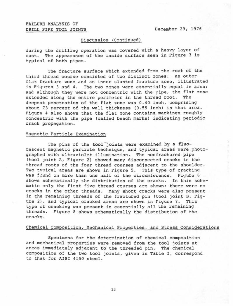
during the drilling operation was covered with a heavy layer ofrust. The appearance of the inside surface seen in Figure 3 istypical of both pipes.
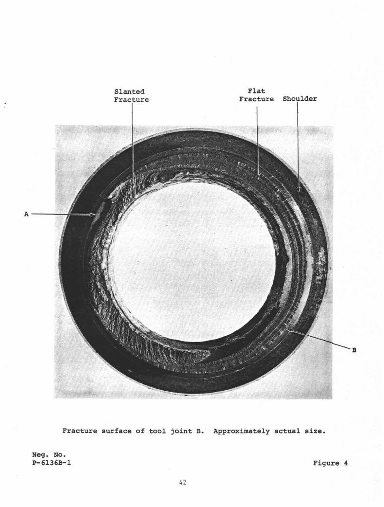
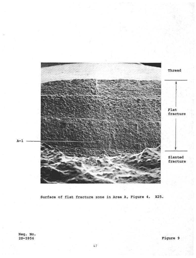
The fracture surface which extended from the root of thethird thread course consisted of two distinct zones: an outerflat fracture zone and an inner slanted fracture zone, illustratedin Figures 3 and 4. The two zones were essentially equal in area;and although they were not concentric with the pipe, the flat zoneextended along the entire perimeter in the thread root. Thedeepest penetration of the flat zone was 0.40 inch, comprisingabout 7 3 percent of the wall thickness (0.55 inch) in that area.Figure 4 also shows that the flat zone contains markings roughlyconcentric with the pipe (called beach marks) indicating periodiccrack propagation.
Magnetic Particle Examination
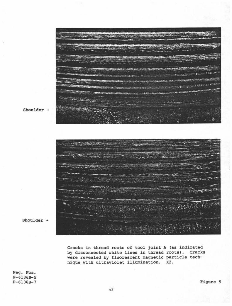
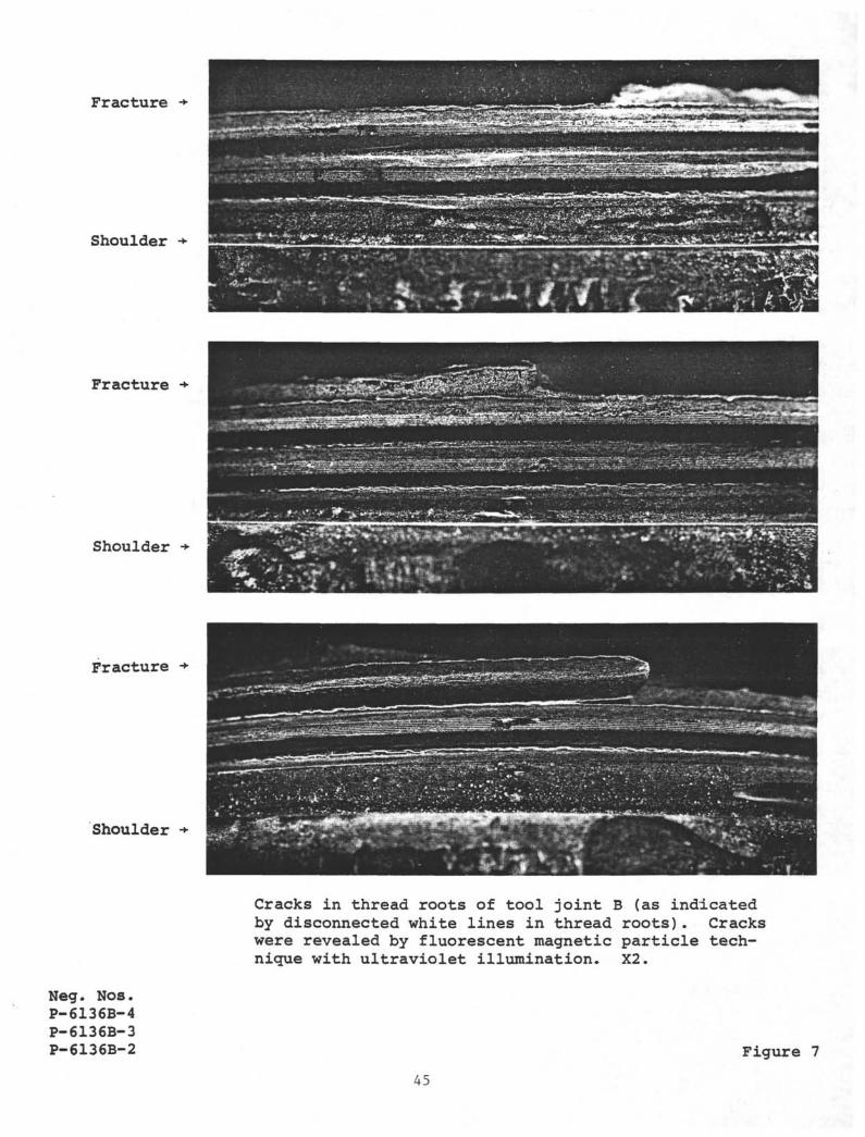
The pins of the tool joints were examined by a fluo-rescent magnetic particle technique, and typical areas were photo-graphed with ultraviolet illumination. The nonfractured pipe(tool joint A, Figure 2) showed many disconnected cracks in thethread roots of the four thread courses adjacent to the shoulder.Two typical areas are shown in Figure 5. This type of crackingwas found on more than one half of the circumference. Figure 6shows schematically the distribution of the cracks. In this sche-matic only the first five thread courses are shown; there were nocracks in the other threads. Many short cracks were also presentin the remaining threads of the fractured pin (tool joint B, Fig-ure 2), and typical cracked areas are shown in Figure 7. Thistype of cracking was present in essentially all the remainingthreads. Figure 8 shows schematically the distribution of thecracks.
Chemical Composition, Mechanical Properties, and Stress Considerations
Specimens for the determination of chemical compositionand mechanical properties were removed from the tool joints atareas immediately adjacent to the threaded pin. The chemicalcomposition of the two tool joints, given in Table I, correspondto that for AISI 4150 steel.
33
FAILURE ANALYSIS OFDRILL PIPE TOOL JOINTS December 2l), 1976
Discussion (Continued)
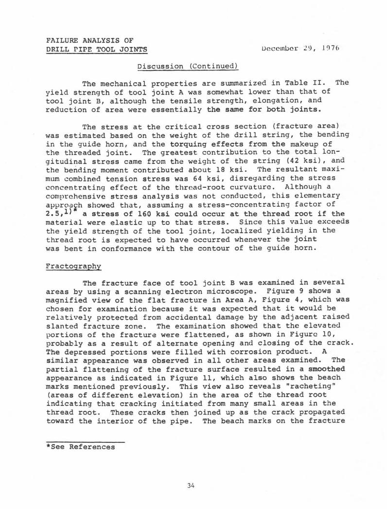
The mechanical properties are summarized in Table II. Theyield strength of tool joint A was somewhat lower than that oftool joint B, although the tensile strength, elongation, andreduction of area were essentially the same for both joints.
The stress at the critical cross section (fracture area)was estimated based on the weight of the drill string, the bendingin the guide horn, and the torquing effects from the makeup ofthe threaded joint. The greatest contribution to the total lon-gitudinal stress came from the weight of the string (42 ksi), andthe bending moment contributed about 18 ksi. The resultant maxi-mum combined tension stress was 64 ksi, disregarding the stressconcentrating effect of the thread-root curvature. Although acomprehensive stress analysis was not conducted, this elementaryapproach showed that, assuming a stress-concentrating factor of2,5,1' a stress of 160 ksi could occur at the thread root if thematerial were elastic up to that stress. Since this value exceedsthe yield strength of the tool joint, localized yielding in thethread root is expected to have occurred whenever the jointwas bent in conformance with the contour of the guide horn.
Fractography
The fracture face of tool joint B was examined in severalareas by using a scanning electron microscope. Figure 9 shows amagnified view of the flat fracture in Area A, Figure 4, which waschosen for examination because it was expected that it would berelatively protected from accidental damage by the adjacent raisedslanted fracture zone. The examination showed that the elevatedportions of the fracture were flattened, as shown in Figure 10,probably as a result of alternate opening and closing of the crackThe depressed portions were filled with corrosion product. Asimilar appearance was observed in all other areas examined. Thepartial flattening of the fracture surface resulted in a smoothedappearance as indicated in Figure 11, which also shows the beachmarks mentioned previously. This view also reveals "racheting"(areas of different elevation) in the area of the thread rootindicating that cracking initiated from many small areas in thethread root. These cracks then joined up as the crack propagatedtoward the interior of the pipe. The beach marks on the fracture
*See References
34
FAILURE ANALYSIS OFDRILL PIPE TOOL JOINTS December 29, 1976
Discussion (Continued)
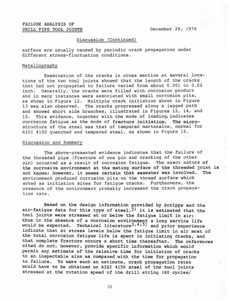
surface are usually caused by periodic crack propagation underdifferent stress-fluctuation conditions.
Metallography
Examination of the cracks in cross section at several loca-tions of the two tool joints showed that the length of the cracksthat had not propagated to failure varied from about 0.001 to 0.02inch. Generally, the cracks were filled with corrosion productand in many instances were associated with small corrosion pits,as shown in Figure 12. Multiple crack initiation shown in Figure13 was also observed. The cracks progressed along a jagged pathand showed short side branches, illustrated in Figures 12, 14, and15. This evidence, together with the mode of loading, indicatescorrosion fatigue as the mode of fracture initiation. The micro-structure of the steel was that of tempered martensite, normal forAISI 4150 quenched and tempered steel, as shown in Figure 15.
Discussion and Summary
The above-presented evidence indicates that the failure ofthe threaded pipe (fracture of one pin and cracking of the otherpin) occurred as a result of corrosion fatigue. The exact nature ofthe corrosive environment at the mating surface of the threaded joint isnot known; however, it seems certain that seawater was involved. Theenvironment produced corrosion pits on the thread surface whichacted as initiation sites for fatigue cracks. Furthermore, thepresence of the environment probably increased the crack propaga-tion rate.
Based on the design information provided by Scripps and theair-fatigue data for this type of steel,2) it is estimated that thetool joints were stressed at or below the fatigue limit in air;thus in the absence of a corrosion environment a long service lifewould be expected. Technical literature3'4'5^ and prior experienceindicate that at stress levels below the fatigue limit in air most ofthe total corrosion fatigue life is spent in initiating cracks, andthat complete fracture occurs a short time thereafter. The referencescited do not, however, provide specific information which wouldpermit any estimate of the relative time for initiation of cracksto an inspectable size as compared with the time for propagationto failure. To make such an estimate, crack propagation rateswould have to be obtained on AISI 4150 steel of the tool jointsstressed at the rotation speed of the drill string (60 cycles/
35
FAILURE ANALYSIS OFDRILL PIPE TOOL JOINTS December 29, 1976
Discussion (Continued)
minute) in an environment simulating the service condition. Analternate empirical approach would be to inspect the pins of pupjoints at relatively frequent intervals to detect crack initia-tion (and also to serve as a basis for replacing any crackedjoint).
References
1. R. E. Peterson, "Stress Concentration Factors" John Wiley &Sons, 1974, p 42, Figure 23.
2. S. T. Rolfe and J. M. Barsoin, Fracture and Fatigue Control inStructures—Applications of Fracture Mechanics! Prentice-Hall, Inc.,Englewood Cliff, N J., 1976.
3. D. W. Hoeppner, "Corrosion Fatigue Considerations in MaterialsSelection and Engineering Design," Corrosion Fatigue, NationalAssociation of Corrosion Engineers, 1972, pp 3-11.
4. W. E. Krupp, D. W. Hoeppner, E. K. Walker, "Crack Propagationof Aluminum Alloys in Corrosive Environments," Corrosion Fatigue,National Association of Corrosion Engineers, 1972, pp 468-483.
5. V. Rollins, B. Arnold, E. Lardner, "Corrosion Fatigue in HighCarbon Steel," British Corrosion Journal, Vol. 5, 1970, pp 33-40.
36
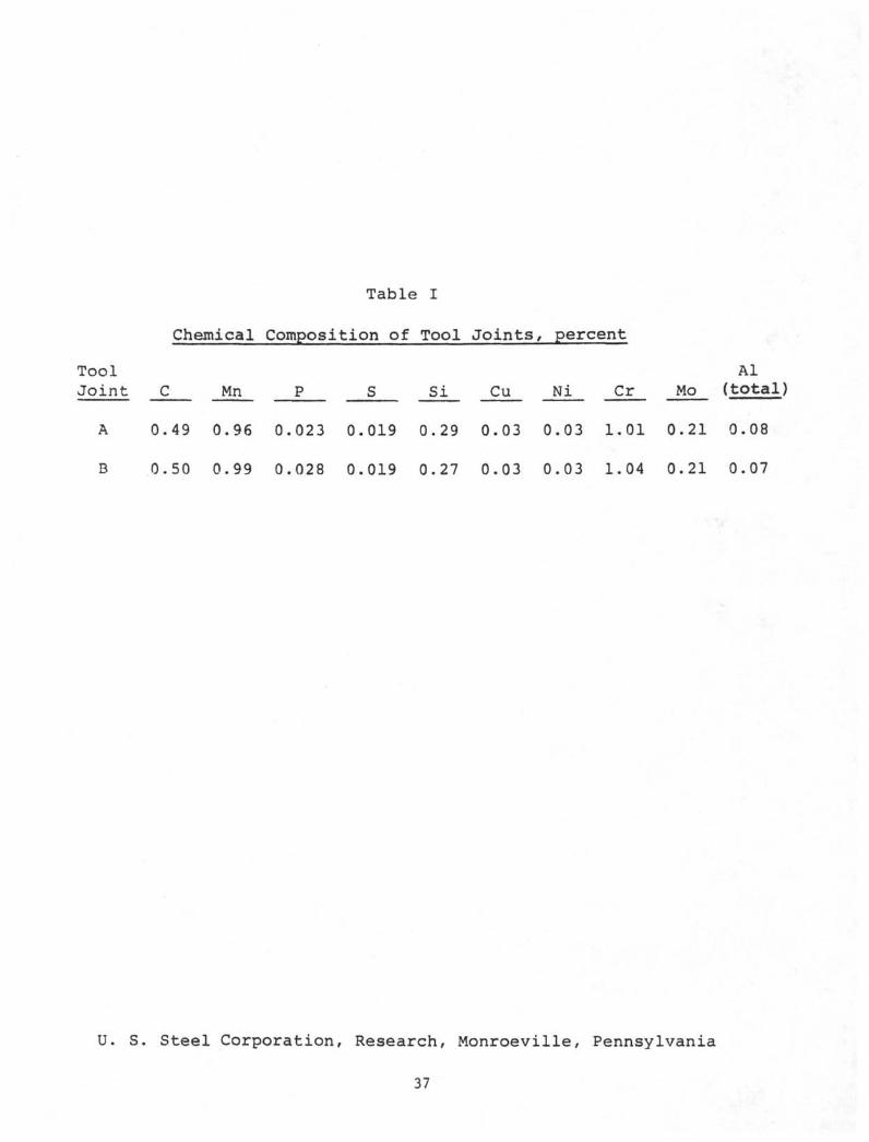
Table I
Chemical Composition of Tool Joints, percent
Tool Al
Joint C Mn P S Si Cu Ni Cr Mo (total)
A 0.49 0.96 0.023 0.019 0.29 0.03 0.03 1.01 0.21 0.08
B 0.50 0.99 0.028 0.019 0.27 0.03 0.03 1.04 0.21 0.07
U. S. Steel Corporation, Research, Monroeville, Pennsylvania
37
ToolJoint
A
B
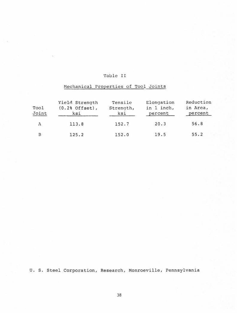
Table II
Mechanical Properties of
Yield Strength(0.2% Offset),
ksi
113.8
125.2
TensileStrength,
ksi
152.7
152.0
Tool Joints
Elongationin 1 inch,percent
20.3
19.5
Reductionin Area,percent
56.8
55.2
U. S. Steel Corporation, Research, Monroeville, Pennsylvania
38
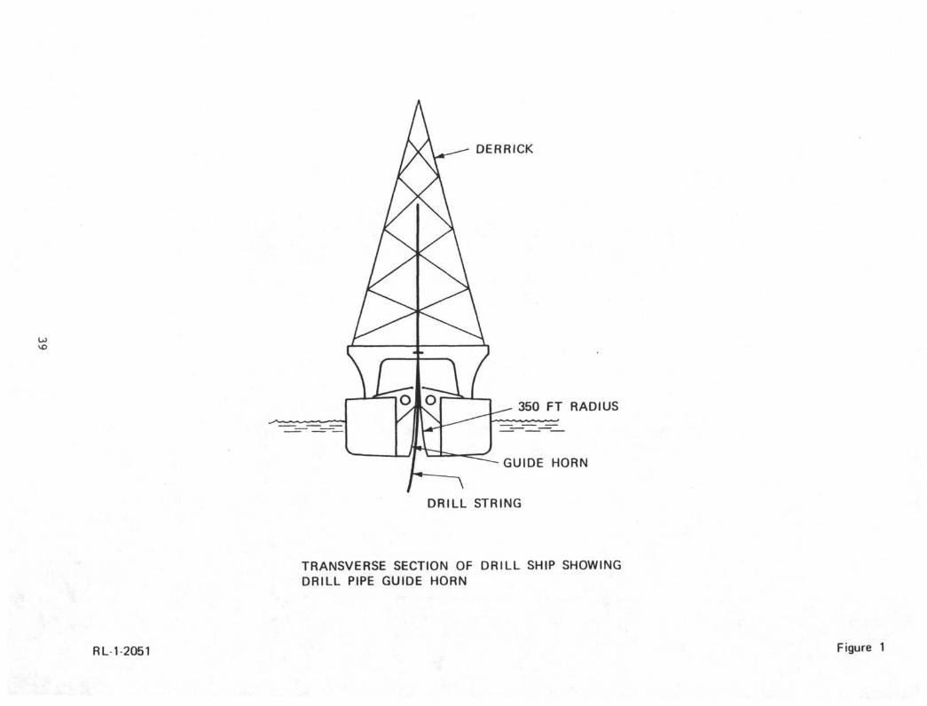
TRANSVERSE SECTION OF DRILL SHIP SHOWINGDRILL PIPE GUIDE HORN
RL 1-2051 Figure 1
ToolJoint
DrillPipe
Fracture
Tool joints A (left) and B (right) submitted forexamination after four years service. About 1/5actual size.
Neg No.P-6116B-1 Figure 2
40
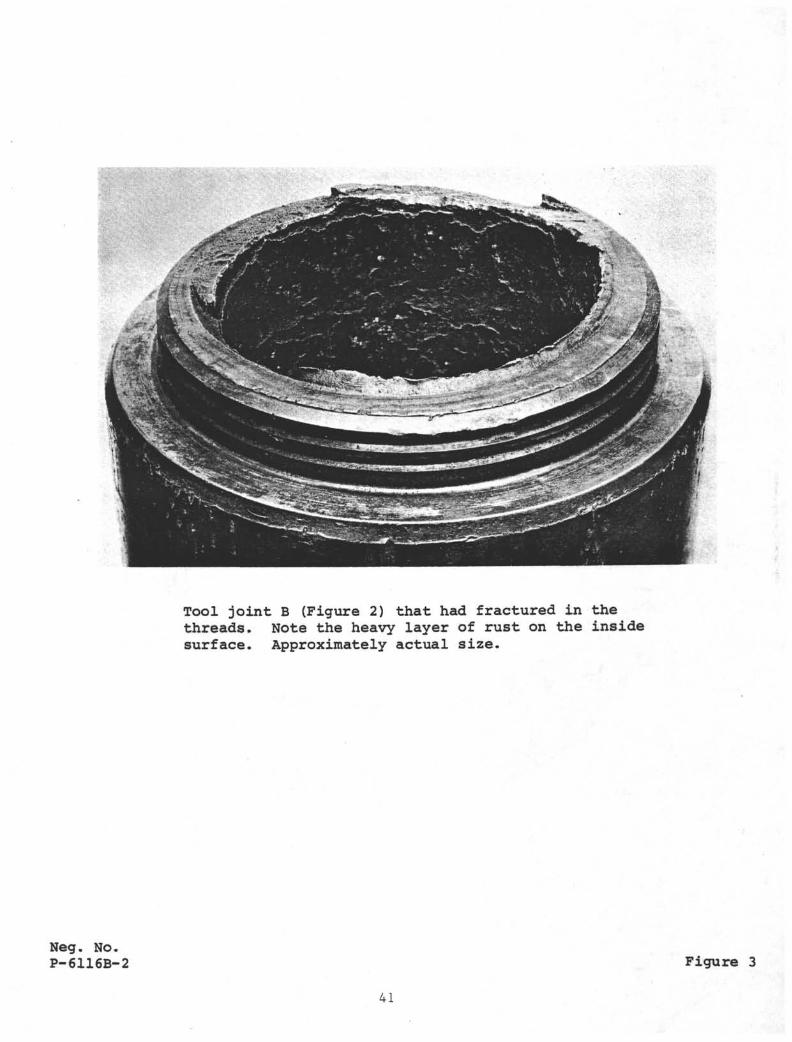
Tool joint B (Figure 2) that had fractured in thethreads. Note the heavy layer of rust on the insidesurface. Approximately actual size.
Neg. No.P-6116B-2 Figure 3
41
SlantedFracture
FlatFracture Shoulder
Fracture surface of tool joint B. Approximately actual size.
Neg. No.P-6136B-1 Figure 4
Shoulder
Shoulder
Neg. Nos.P-6136B-5P-6136B-7
Cracks in thread roots of tool joint A (as indicatedby disconnected white lines in thread roots). Crackswere revealed by fluorescent magnetic particle tech-nique with ultraviolet illumination. X2.
Figure 5
43
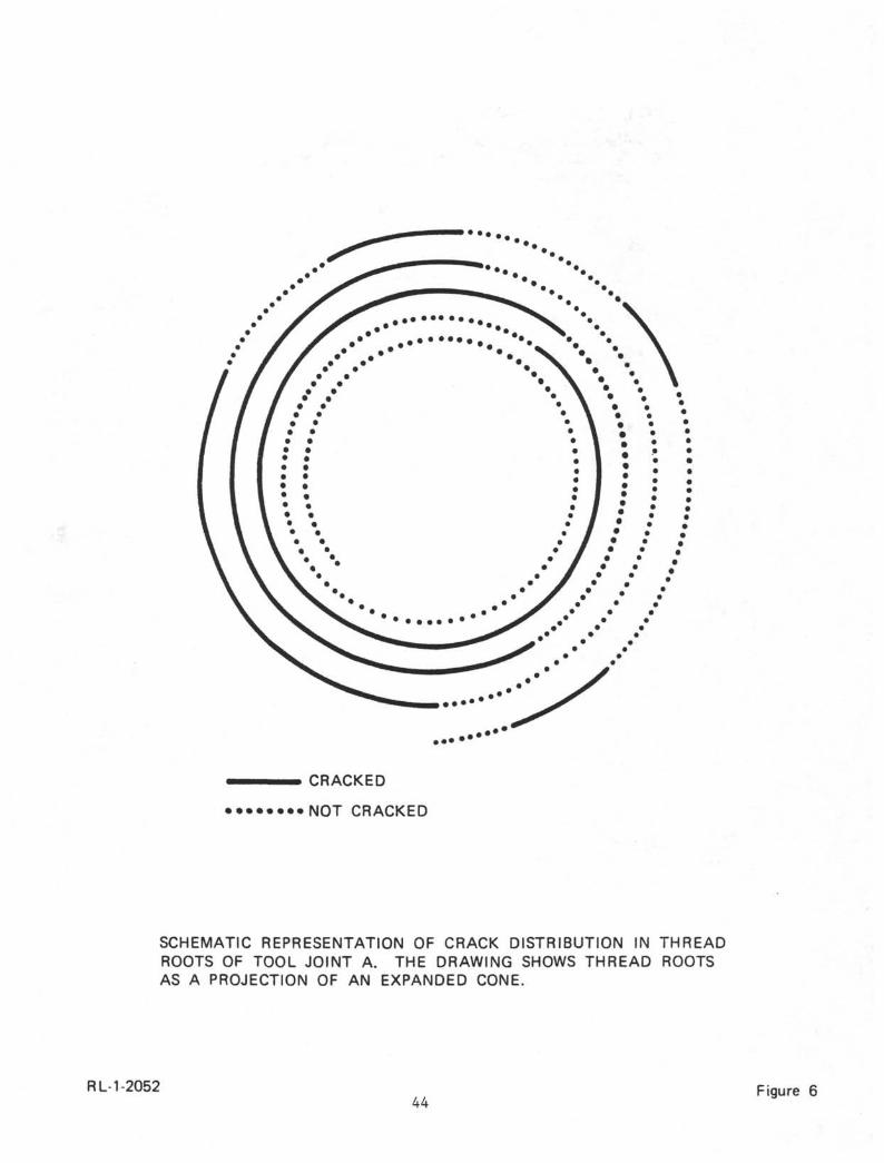
CRACKED
• • • • • • • • N O T CRACKED
SCHEMATIC REPRESENTATION OF CRACK DISTRIBUTION IN THREADROOTS OF TOOL JOINT A. THE DRAWING SHOWS THREAD ROOTSAS A PROJECTION OF AN EXPANDED CONE.
RL-1-205244
Figure 6
Fracture
Shoulder
Fracture
Shoulder
Fracture
Shoulder •
Neg. Nos.P-6136B-4P-6136B-3P-6136B-2
Cracks in thread roots of tool joint B (as indicatedby disconnected white lines in thread roots). Crackswere revealed by fluorescent magnetic particle tech-nique with ultraviolet illumination. X2.
Figure 7
45
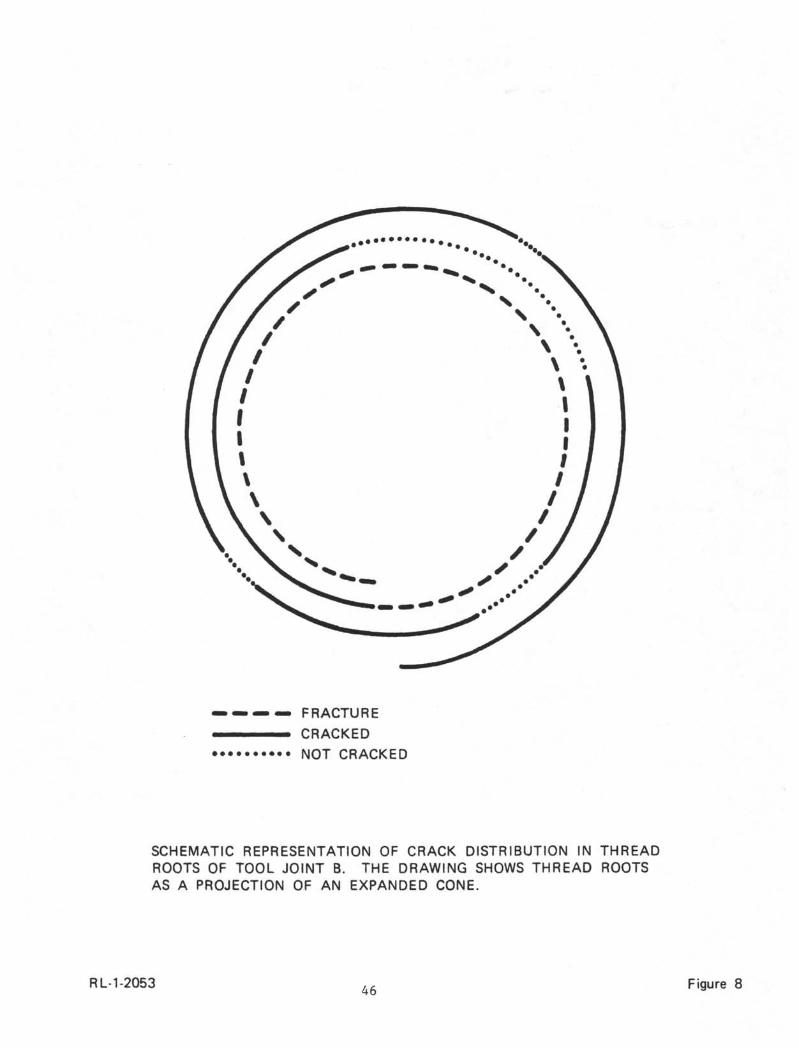
FRACTURECRACKED
• NOT CRACKED
SCHEMATIC REPRESENTATION OF CRACK DISTRIBUTION IN THREADROOTS OF TOOL JOINT B. THE DRAWING SHOWS THREAD ROOTSAS A PROJECTION OF AN EXPANDED CONE.
RL-1-2053 46 Figure 8
Thread
A-l
Flatfracture
Slantedfracture
Surface of flat fracture zone in Area A, Figure 4. X25.
Neg. No.2S-5956 Figure 9
47
Flattenedportion
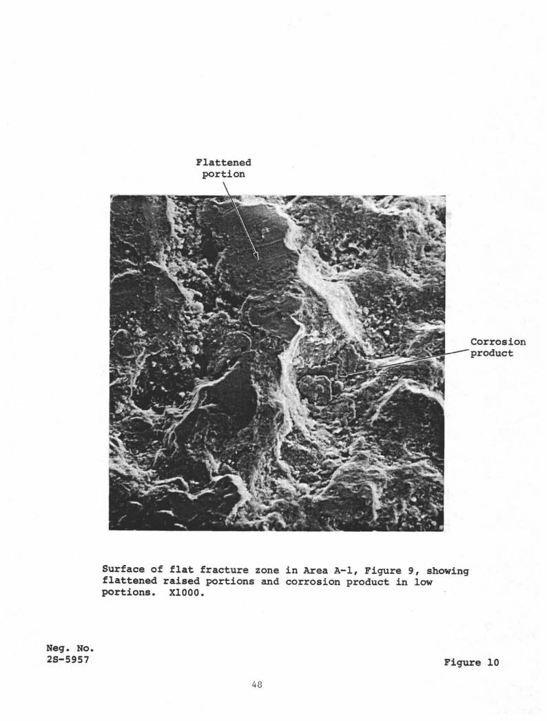
Corrosionproduct
Surface of flat fracture zone in Area A-l, Figure 9, showingflattened raised portions and corrosion product in lowportions. X1000.
Neg. No.2S-5957 Figure 10
48
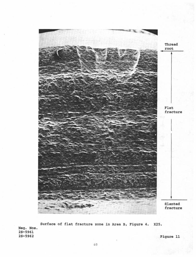
Threadroot
Flatfracture
Slantedfracture
Neg. Nos.2S-59612S-5962
Surface of flat fracture zone in Area B, Figure 4. X25.
Figure 11
49
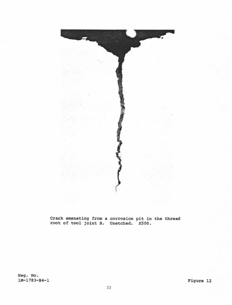
Crack emanating from a corrosion pit in the threadroot of tool joint B. Unetched. X500.
Neg. No.1M-1783-B4-1 Figure 12
50
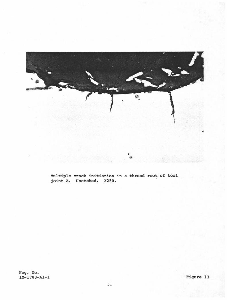
Multiple crack initiation in a thread root of tooljoint A. ünetched. X250.
Neg. No.IM-178 3-Al-1 Figure 13
51
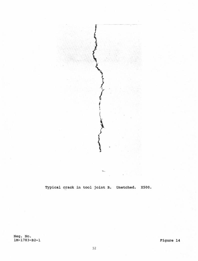
Typical crack in tool joint B. ünetched. X500.
Neg. No.1M-1783-B2-1 Figure 14
52
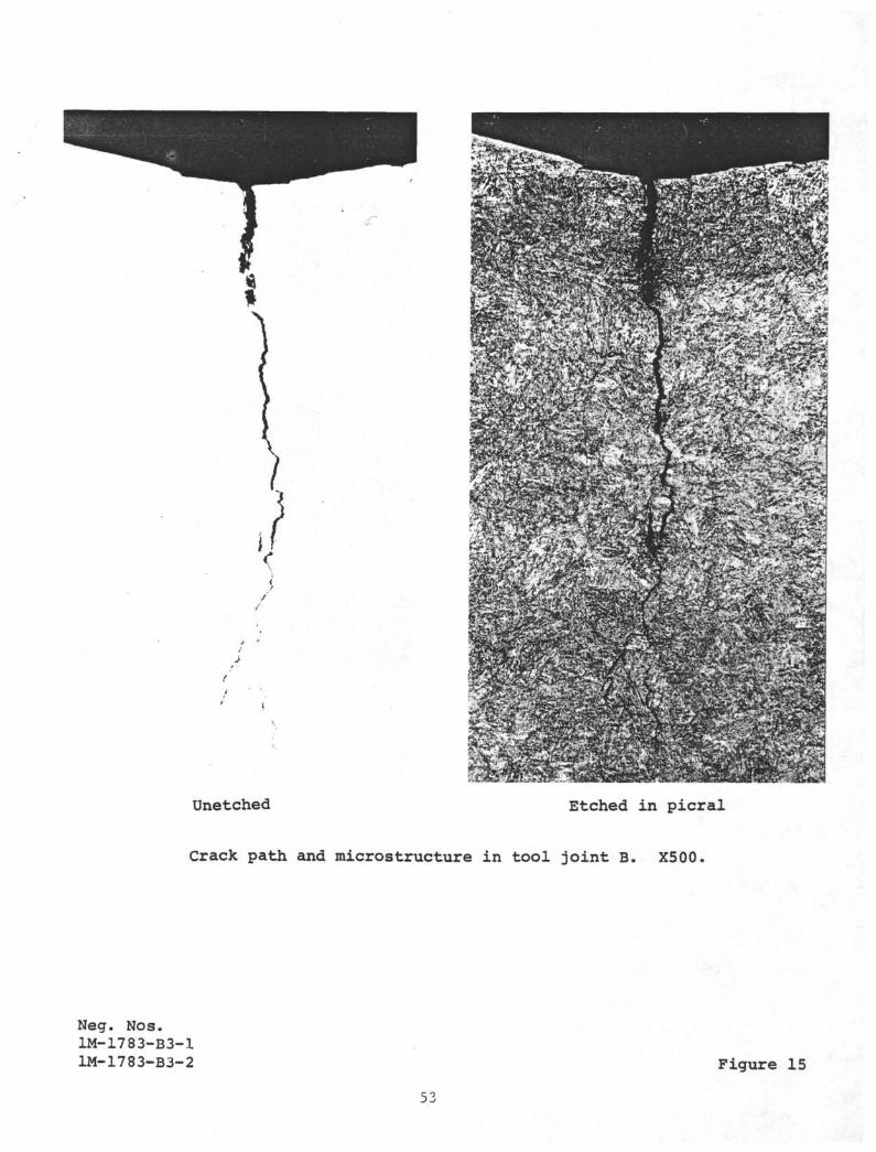
ünetched Etched in picral
Crack path and microstructure in tool joint B. X500.
Neg. Nos.1M-1783-B3-11M-1783-B3-2 Figure 15
53
APPENDIX B-2
FAILURE ANALYSIS OF S-135 DRILL PIPEUSED IN DEEP SEA DRILLING
(LEG 53)
BULLETIN
ResearchUnited States Steel Corporation
Monroeville, PennsylvaniaNovember 8, 1977
FAILURE ANALYSIS OF S-135 DRILL PIPEUSED IN DEEP SEA DRILLING
Summary
Scripps Institution of Oceanography contracted withU. S. Steel Research to analyze failures of three sections ofAPI Specification 5AX Grade S-135 drill pipe. The drill pipesfractured during drilling operations in seawater at considerabledepths.
The study confirmed that the chemical composition,mechanical properties, and microstructure are typical for S-135drill pipe. Fractographic and metallographic examinationsshowed that the failures occurred as a result of corrosion fatigueinitiating on the external surface of the drill pipe. Corrosionpitting on the fracture surfaces of cracks that progressedpartially through the pipe wall suggests that the corrosion fatiguecracks progressed relatively slowly permitting sufficient time forcorrosion pits to grow on the newly exposed crack surfaces. How-ever, specific information was not available to permit an estimateof the time-to-failure after crack initiation.
(Discussion attached)
57
FAILURE ANALYSIS OFS-135 DRILL PIPE USED
IN DEEP SEA DRILLING * November 8, 1977
Discussion
Introduction
Scripps Institution of Oceanography (University ofCalifornia) experienced failure of a drill pipe (API Specification5AX Grade S-135) used in the Deep Sea Drilling Project being con-ducted for the National Science Foundation. During service, thedrill pipe is immersed in seawater to a considerable depth andaerated seawater is pumped through the pipe.
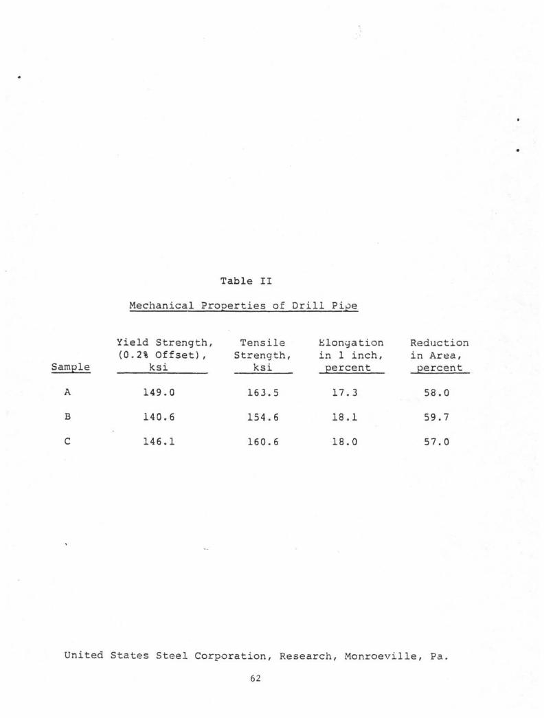
Three samples of failed pipes were submitted for examinationThe chemical composition and mechanical properties, shown inTables I and II, respectively, and the microstructure are typicalfor S-135 drill pipe. One sample received in April 1977 withoutidentification will be referred to as Sample A. Two other samplesreceived in July 1977 were identified as 53418A. One of thesecame in two pieces (2A and 2B) representing mating faces of afracture; this pipe will be referred to as Sample B. The otherpipe sample (53418A1) received in July contained a threaded tooljoint and will be referred to as Sample C.
Sample A
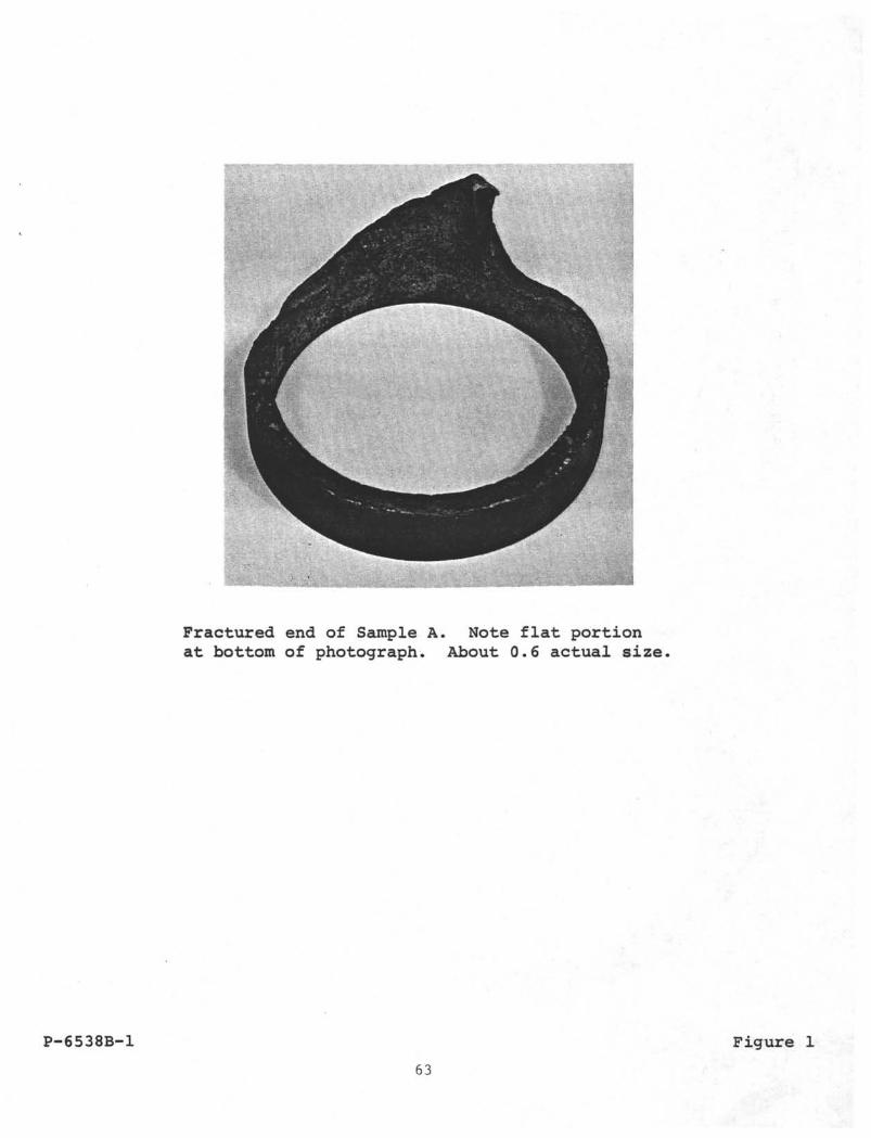
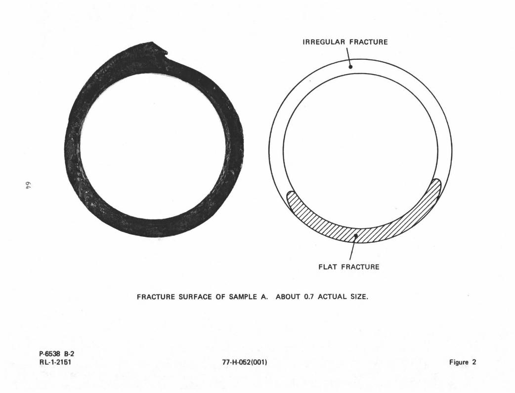
This pipe sample (5.5-inch OD, 0.42-inch wall) had afracture on one of its ends consisting of a flat portion thatextended for about one third of the circumference and of an irreg-ular portion. Figure 1 shows a portion of the pipe containingthe fracture face, and Figure 2 shows the relative positions ofthe flat and irregular fractures. The flat portion, extendingessentially normal to the pipe axis, indicates that the initialfracture was caused by a predominantly axial load. After theinitial flat fracture extended to critical size, the remainingportion failed by overload in an irregular manner. The insidesurface was more severely corroded than the outside and containedmany irregularly shaped pits, as is illustrated in Figure 3. Nosecondary cracks were observed on the inside surface. The highercorrosion rate on the inside is believed to be the result of highoxygen concentration from some air entrapment and of high flow rate.
The outside surface was corroded to an appreciably lesserextent than the inside surface, the corrosion was more general innature, and pitting was shallow and infrequent. In addition, many
58
FAILURE ANALYSIS OF
S-135 DRILL PIPE USED
IN DEEP SEA DRILLING ;
:~ November 8, 1977
Discussion (Continued)
small cracks were present on the outside surface immediately
adjacent to the flat fracture. Typical cracks are shown in
Figure 4. Considerable lateral corrosion also occurred in some
of the cracks as depicted in Figure 5.
The fracture surface was severely corroded, thereby obscur-
ing the original features of the fracture face. Removal of corro-
sion products*) from the flat fracture section revealed small, deep
pits and cracks essentially perpendicular to the fracture surface,
as illustrated in Figure 6.
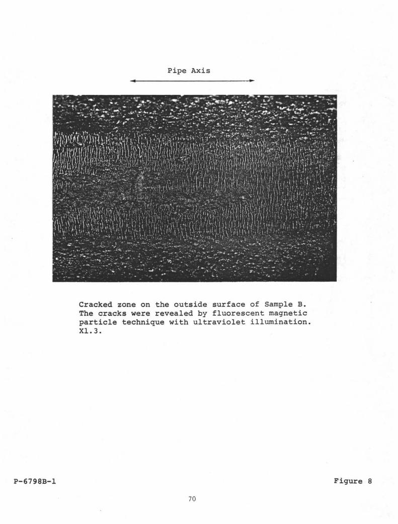
Sample B
Sample B represents two matching sections of a pipe
(5-inch OD, 0.35-inch wall) that had fractured. The fractured ends
of the pipe are shown in Figure 7. Similar to Sample A, this pipe
sample also contained a flat portion in its fracture surface
extending about one third of the circumference, the remainder of the
fracture being irregular. Fluorescent magnetic particle examination
revealed longitudinal bands of circumferential cracks adjacent to
the flat fracture, as schematically indicated in Figure 7. A
detailed view of one cracked zone is shown in Figure 8.
Metallographic examination showed that these cracks, about
0.01 inch .deep, were filled with corrosion product as is illustrated
in Figure 9. Considerable corrosion was also present on the frac-
ture face indicating that the pipe was exposed to seawater for an
appreciable time after the fracture occurred. In addition to
general corrosion, deep narrow pits were present on the fracture
surface, Figures 10 and 11. The fracture surface adjoining the
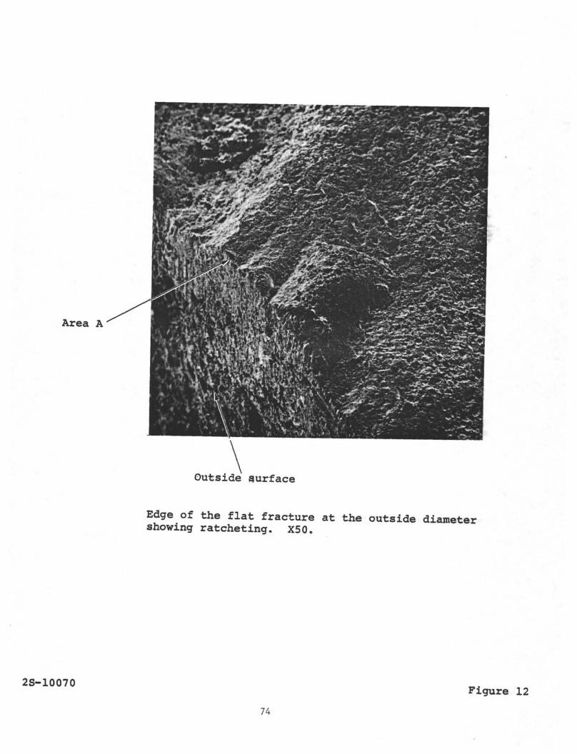
outside diameter of the pipe revealed "ratcheting" (areas of dif-
ferent elevation) illustrated in Figure 12. This configuration
indicates that the flat fracture initiated from many small cracks
on, the outside surface, such as those shown in Figure 8, which then
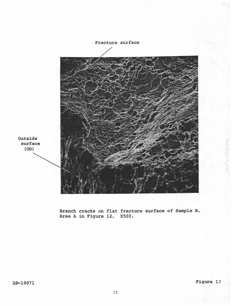
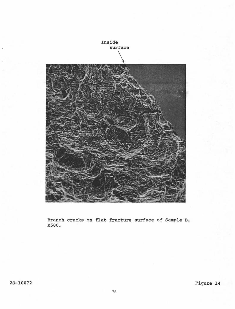
joined up as the crack propagated. Branch cracks were also seen
on the fracture surface, as is illustrated in Figures 13 and 14,
for areas at the outside and inside pipe surfaces, respectively.
*) The corrosion products were removed ultrasonically in an
13 percent HCl solution inhibited by 5 g/1 of l,3-D~n-butyl-2
thiourea. This solution does not attack steel, but it removes
rαst and exposed sulfide inclusions.
59
FAILURE ANALYSIS OFS-135 DRILL PIPE USED
IN DEEP SEA DRILLING November 3, 1977
Discussion (Continued)
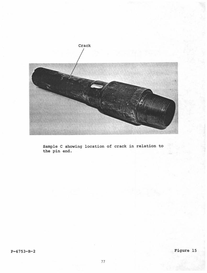
Sample C
This sample, shown in Figure 15, consisted of a 5-inch OD,0.35-inch wall pipe section attached to a tool joint. About 24inches from the pin end, the pipe contained a rather straightcircumferential crack about 1.5 inches long; Figure 15 shows thelocation of the crack. The outside pipe surface in the vicinityof the crack was ground off before receipt of the sample. A metal-lographic section at about midlength of the crack showed that thecrack was very straight. Although in this section the crack hadnot propagated through the pipe wall, in an adjacent area the crackdid penetrate the crack wall. Figure 16 shows that the crackinitiated on the outside surface, and that pitting corrosionoccurred laterally from the crack, indicating that the crack propa-gated relatively slowly. The straightness of the crack is typicalof fatigue cracks. The tip of the crack follows a slightlybranched, predominantly transgranular path, as illustrated inFigure 17. Although the crack initiation area could be identified,as shown in Figure 18, the grinding of the outside surface precludedlinking the exact initiation site with metallographic or corrosionfeatures.
Discussion and Summary
Examination of three sections of API Grade S-135 drillpipe that failed during drilling operations in seawater revealedseveral features which indicate that the fractures occurred as aresult of corrosion fatigue. Multiple crack initiation occurredon the outside surface, the cracks propagated rather slowly, and thecracks were filled with corrosion product. The flatness of thefracture being essentially normal to the pipe axis indicates thatthe load was predominantly axial. The remainder of the fracture,which was irregular, was caused by overload after the fatigue crackha,d progressed to a critical size.
Although the inside surface of the pipe contained appre-ciably more and deeper corrosion pits than the outside, the corro-sion fatigue cracks started from the outside surface. Lateralpitting corrosion on the fracture surfaces of cracks that progressedpartially through the pipe wall indicates that the cracks progressedrelatively slowly permitting sufficient time for corrosion pits togrow on the newly exposed crack surfaces. Hov/ever, specific infor-mation was not available that would permit an estimate of the time-to-failure after crack initiation.
60
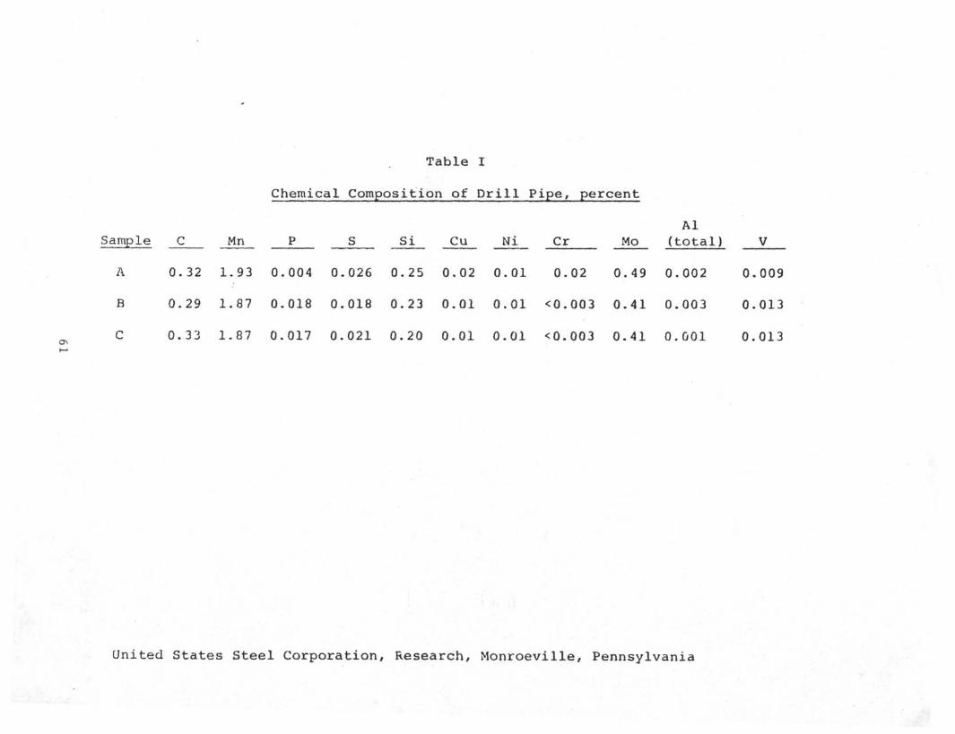
Table I
Chemical Composition of Drill Pipe, percent
AlSample C Mn P S Si Cu Ni Cr Mo (total) V
United States Steel Corporation, Research, Monroeville, Pennsylvania
A 0.32 1.93 0.004 0.026 0.25 0.02 0.01 0.02 0.49 0.002 0.009
B 0.29 1.87 0.018 0.018 0.23 0.01 0.01 <0.003 0.41 0.003 0.013
C 0.33 1.87 0.017 0.021 0.20 0.01 0.01 <0.003 0.41 0.001 0.013
Sample
A
B
C
Table II
Mechanical Properties of
Yield Strength,(0.2% Offset),
ksi
149.0
140.6
146.1
TensileStrength
ksi
163.5
154.6
160.6
Drill Pipe
Elongation, in 1 inch,
percent
17.3
18.1
18.0
Reductionin Area,percent
58.0
59.7
57.0
United States Steel Corporation, Research, Monroeville, Pa.
62
Fractured end of Sample A. Note flat portionat bottom of photograph. About 0.6 actual size
P-6538B-1 Figure 1
63
IRREGULAR FRACTURE
FLAT FRACTURE
FRACTURE SURFACE OF SAMPLE A. ABOUT 0.7 ACTUAL SIZE.
P-6538 B-2RL-1-2151 77-H-052(001) Figure 2
Irregularly-shaped corrosion pit on the insidesurface of Sample A. Not etched. X300.
1M-1834-A-3 Figure 3
65
;?K^1?*^f%yM^
if *
' , ' V(,•
, ,* 'v ;
^;:.
i^W^ ^ • ^-.,««
• hr- mmi
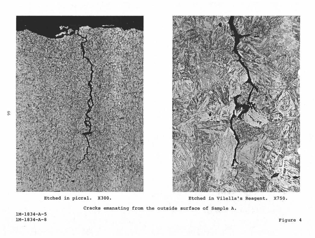
1M-1834-A-51M-1834-A-8
• H • • • H IEtched in picral. X300. Etched in Vilella1s Reagent. X750.
Cracks emanating from the outside surface of Sample A.
Figure 4
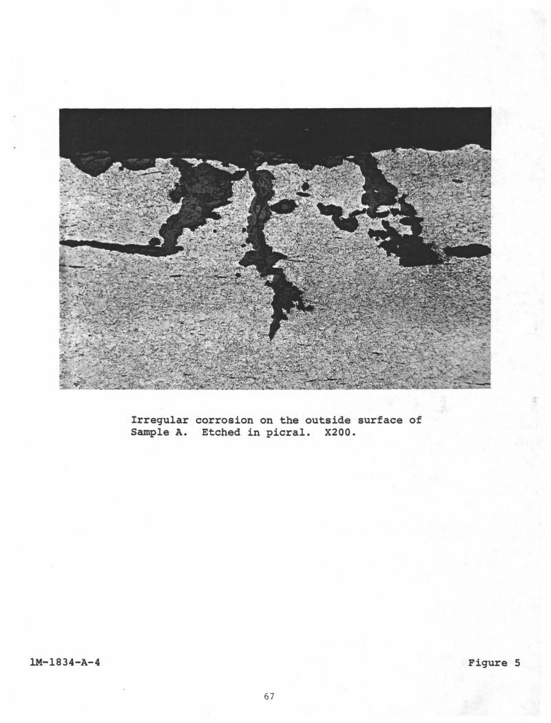
=•' " ~ .
Irregular corrosion on the outside surface ofSample A. Etched in picral. X200.
.
1M-1834-A-4 Figure 5
67
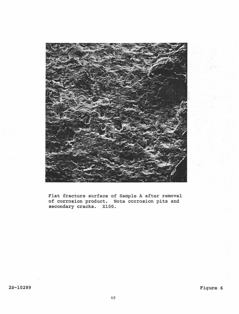
Flat fracture surface of Sample A after removalof corrosion product. Note corrosion pits andsecondary cracks. X100.
2S-10289
68
Figure 6
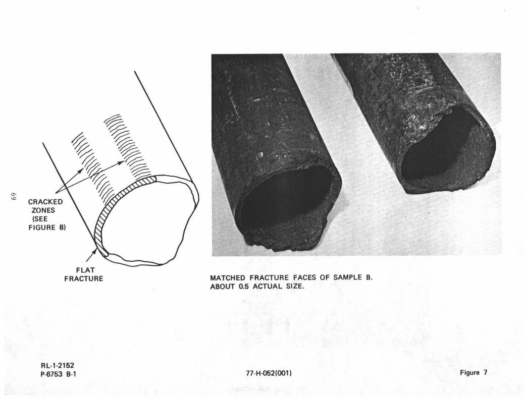
CRACKEDZONES(SEEFIGURE 8)
FLATFRACTURE MATCHED FRACTURE FACES OF SAMPLE B.
ABOUT 0.5 ACTUAL SIZE.
RL-1-2152P-6753 B-1 77-H-052(001) Figure 7
Pipe Axis
Cracked zone on the outside surface of Sample B.The cracks were revealed by fluorescent magneticparticle technique with ultraviolet illumination.XI.3.
P-6798B-1 Figure 8
70
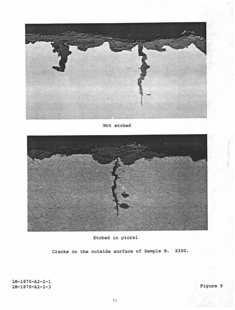
Not etched
Etched in picral
Cracks on the outside surface of Sample B. X200
1M-1870-A2-2-11M-1870-A2-2-3 Figure 9
71
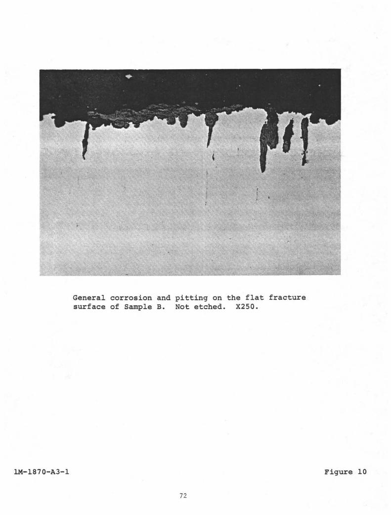
General corrosion and pitting on the flat fracturesurface of Sample B. Not etched. X250.
1M-1870-A3-1 Figure 10
72
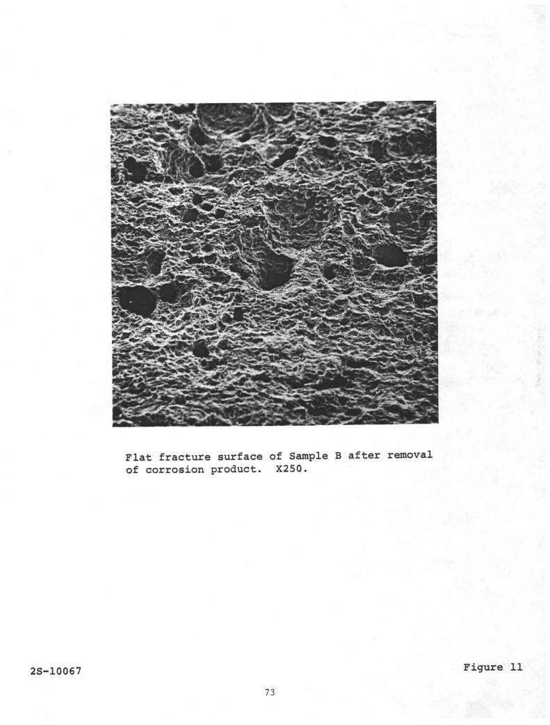
Flat fracture surface of Sample B after removalof corrosion product. X250.
2S-10067 Figure 11
73
Area A
Outside surface
Edge of the flat fracture at the outside diametershowing ratcheting. X50.
2S-10070Figure 12
74
Fracture surface
Outsidesurface(OD)
:
Branch cracks on flat fracture surface of Sample B,Area A in Figure 12. X500.
2S-10071 Figure 13
75
Insidesurface
Branch cracks on flat fracture surface of Sample B,X500.
2S-10072 Figure 14
76
Crack
Sample C showing location of crack in relation tothe pin end.
P-6753-B-2 Figure 15
77
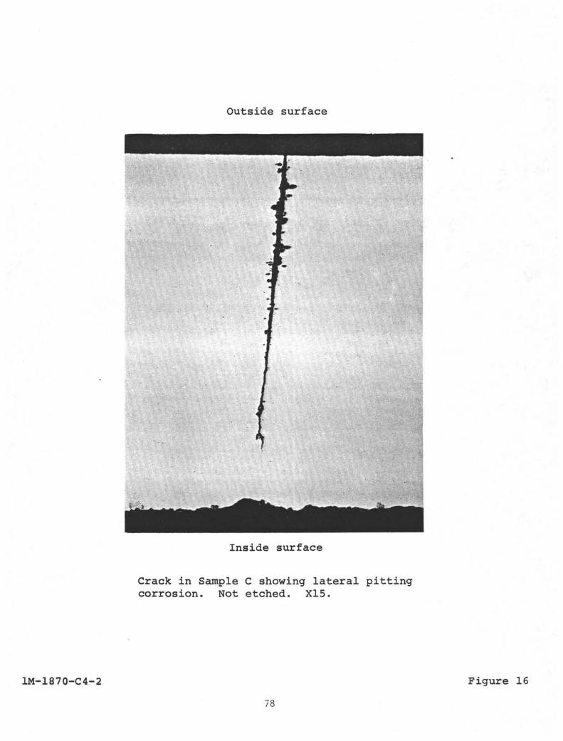
Outside surface
Inside surface
Crack in Sample C showing lateral pittingcorrosion. Not etched. X15.
1M-1870-C4-2 Figure 16
78
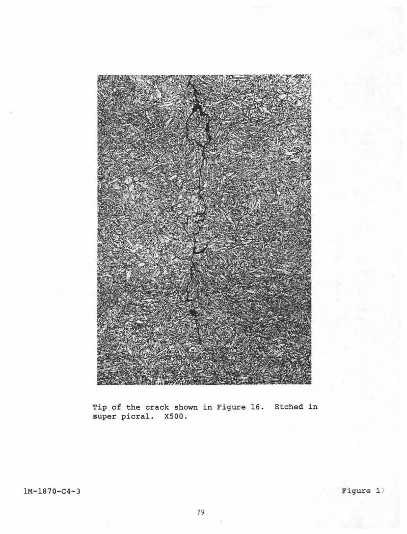
Tip of the crack shown in Figure 16. Etched insuper picral. X500.
1M-1870-C4-3 Figure 1/
79
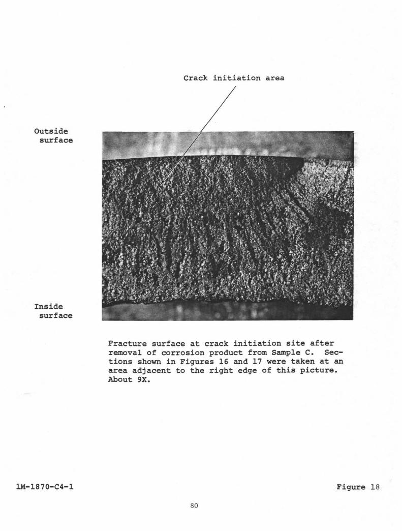
Crack initiation area
Outsidesurface
Insidesurface
Fracture surface at crack initiation site afterremoval of corrosion product from Sample C. Sec-tions shown in Figures 16 and 17 were taken at anarea adjacent to the right edge of this picture.About 9X.
1M-1870-C4-1 Figure 18
80
APPENDIX B-3
DOCKSIDE PRELIMINARY EXAMINATION OFFAILED S-135 STEEL DRILL PIPE FROMD/V GLOMAR CHALLENGER AND ASSOCIATEDMETALLURGICAL FAILURE ANALYSIS OF
FRACTURED DRILL PIPE, LEG 83, HOLE 5O4B
REPORT
on
DOCKSIDE PRELIMINARY EXAMINATION OFFAILED S-135 STEEL DRILL PIPE FROM. GLOMAR CHALLENGER AND ASSOCIATED
METALLURGICAL FAILURE ANALYSIS OFFRACTURED DRILL PIPELEG 83, HOLE 504B
Contract No. G 12696-3058
to
DEEP SEA DRILLING PROJECT
March 30, 1982
by
D. R. Mclntyre
BATTELLE .Houston Operations
2223 West Loop SouthHouston, Texas
Battelie is not engaged in research for advertising, salespromotion, or publicity purposes, and this report may not be reproducedin full or in part for such purposes.
83
TABLE OF CONTENTS
Page
SUMMARY 1
INTRODUCTION 1
Visual Examination 2
Scanning Electron Microscope Fractography 4
Metallographic Examination 4
Mechanical Properties Tests 5
Chemical Composition 5
Discussion 5
Conclusions 7
LIST OF TABLES
Table 1 . Mechanical Properties of Cracked Dr i l l Pipe (Average)of Two Specimens) 9
Table 2. Chemical Composition of Field Dr i l l Pipe (Sample) 10
LIST OF FIGURES
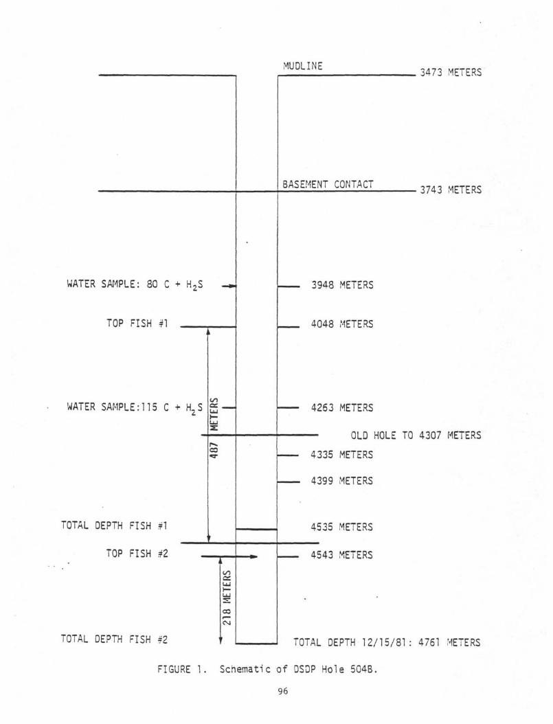
Figure 1. Schematic of DSDP Hole 504B.. . . . 11
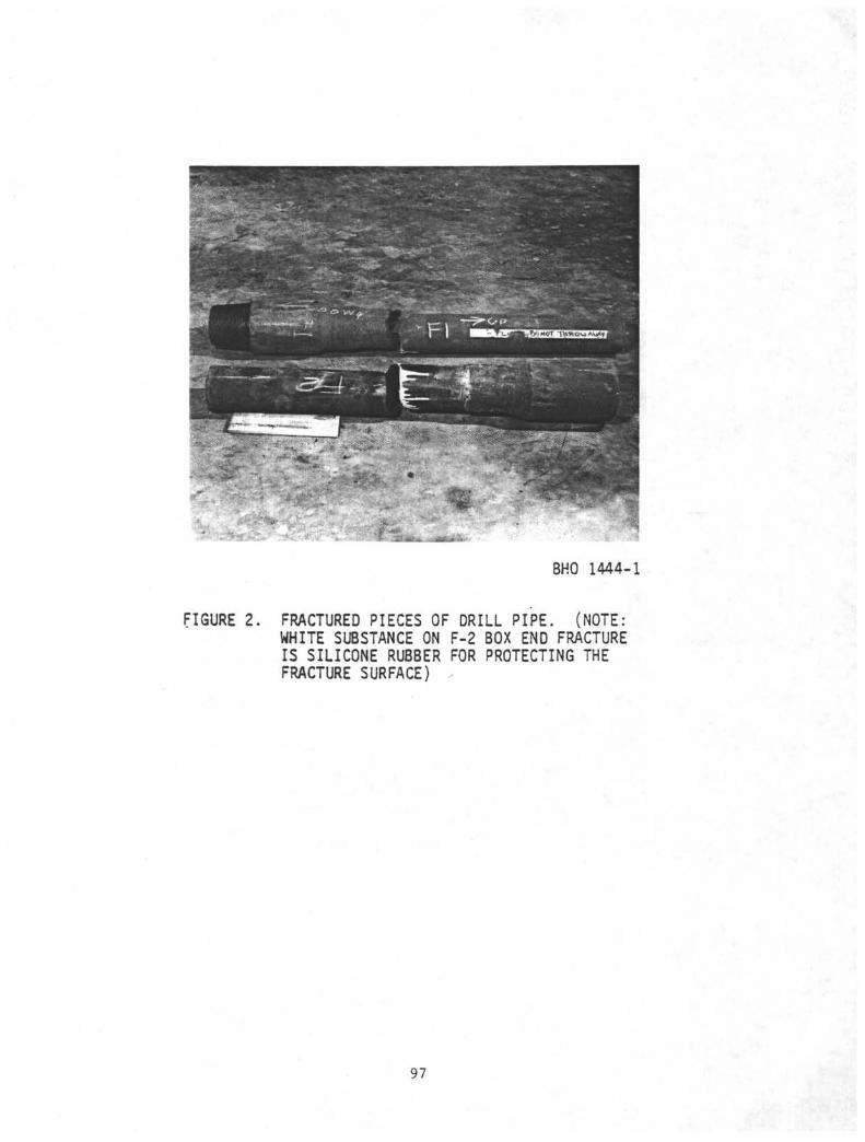
Figure 2. Fractured Pieces of Dr i l l Pipe.. 12
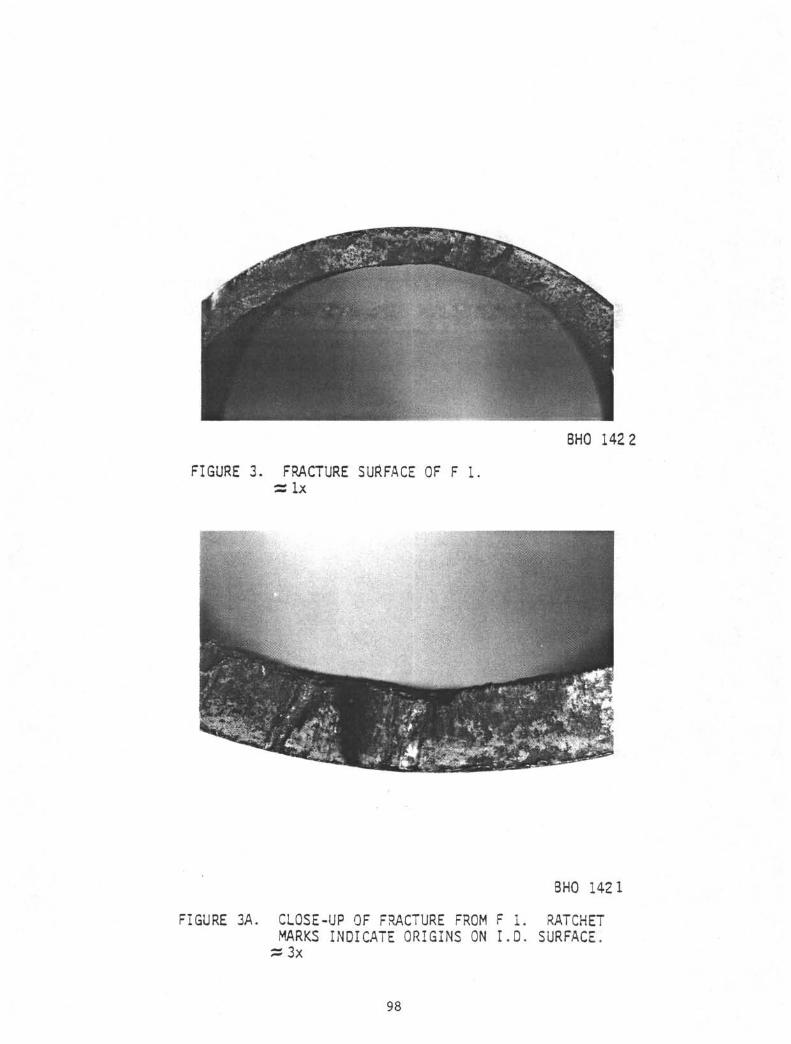
Figure 3. Fracture Surface of F 1 13
Figure 3A. Close-up of Fracture from F 1 13
Figure 4. Fracture Surface of F 2 14
Figure 4A. Close-up of Fracture from F 2 14
84
TABLE OF CONTENTS
ç (continued)
LIST OF FIGURES
(continued)
Page
Figure 5. Cracked Pipe Joints 15
Figure 6. Fracture Surface of Crack Exposed in Sample A 16
Figure 7. Close-up of Fracture Surface from Sample A 16
Figure 8. Fracture Surface Exposed in Sample B 17
Figure 9. Close-up of Fracture Surface from Sample B 17
Figure 10. Photomicrograph from a Section Through a Fracture Originon Sample F 1 18
Figure 11. Higher-Magnification Photomicrograph of Origin in Figure10 18
Figure 12. Photomicrograph from a Section Through a Fracture Originon Sample A 19
Figure 13. Higher Magnification Photomicrograph of Origin in Figure12 19
85
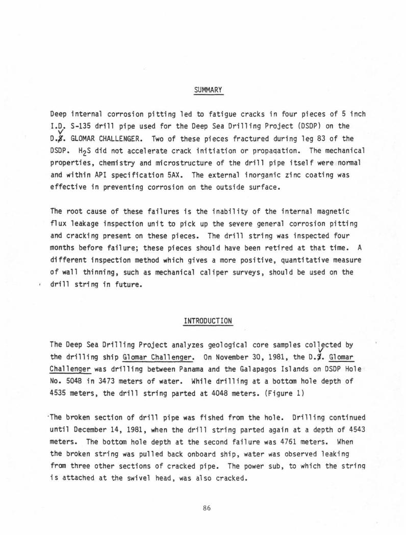
SUMMARY
Deep internal corrosion pitting led to fatigue cracks in four pieces of 5 inch
I.D. S-135 drill pipe used for the Deep Sea Drilling Project (DSDP) on the
O.ß. GLOMAR CHALLENGER. Two of these pieces fractured during leg 83 of the
DSDP. H2S did not accelerate crack initiation or propagation. The mechanical
properties, chemistry and microstructure of the drill pipe itself were normal
and within API specification 5AX. The external inorganic zinc coating was
effective in preventing corrosion on the outside surface.
The root cause of these failures is the inability of the internal magnetic
flux leakage inspection unit to pick up the severe general corrosion pitting
and cracking present on these pieces. The drill string was inspected four
months before failure; these pieces should have been retired at that time. A
different inspection method which gives a more positive, quantitative measure
of wall thinning, such as mechanical caliper surveys, should be used on the
drill string in future.
INTRODUCTION
The Deep Sea Drilling Project analyzes geological core samples collected by
the drilling ship Glomar Challenger. On November 30, 1981, the D.#. Glomar
Challenger was drilling between Panama and the Galapagos Islands on DSDP Hole
No. 504B in 3473 meters of water. While drilling at a bottom hole depth of
4535 meters, the drill string parted at 4048 meters. (Figure 1)
The broken section of drill pipe was fished from the hole. Drilling continued
until December 14, 1981, when the drill string parted again at a depth of 4543
meters. The bottom hole depth at the second failure was 4761 meters. When
the broken string was pulled back onboard ship, water was observed leaking
from three other sections of cracked pipe. The power sub, to which the string
is attached at the swivel head, was also cracked.
86
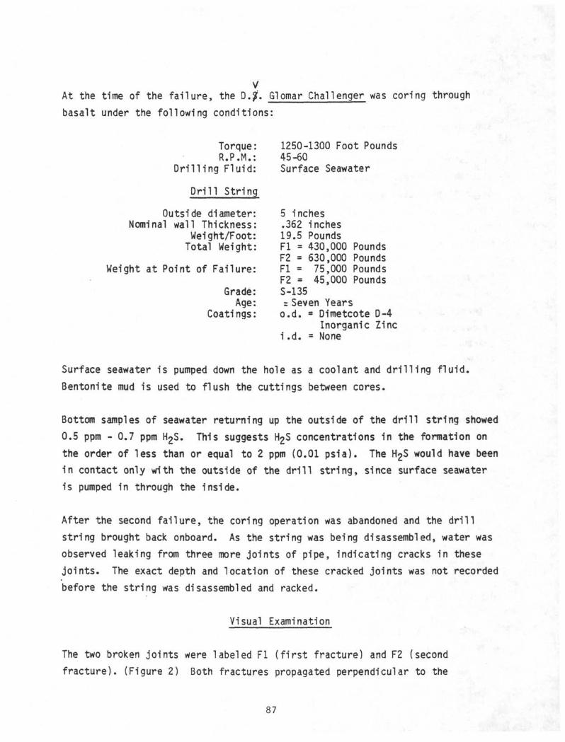
yAt the time of the fa i lure, the .$. Glomar Challenger was coring through
basalt under the following conditions:
Torque: 1250-1300 Foot PoundsR.P.M.: 45-60
Dri l l ing Fluid: Surface Seawater
Dr i l l String
Outside diameter: 5 inchesNominal wall Thickness: .362 inches
Weight/Foot: 19.5 PoundsTotal Weight: Fl = 430,000 Pounds
F2 = 630,000 PoundsWeight at Point of Failure: Fl = 75,000 Pounds
F2 = 45,000 PoundsGrade: S-135
Age: = Seven YearsCoatings: o.d. Dimetcote D-4
Inorganic Zinci .d. = None
Surface seawater is pumped down the hole as a coolant and dr i l l ing f lu id .
Bentonite mud is used to flush the cuttings between cores.
Bottom samples of seawater returning up the outside of the dr i l l string showed
0.5 ppm - 0.7 ppm h^S. This suggests H£S concentrations in the formation on
the order of less than or equal to 2 ppm (0.01 psia). The H2S would have been
in contact only with the outside of the dr i l l string, since surface seawater
is pumped in through the inside.
After the second fa i lure, the coring operation was abandoned and the dr i l l
string brought back onboard. As the string was being disassembled, water was
observed leaking from three more joints of pipe, indicating cracks in these
joints. The exact depth and location of these cracked joints was not recorded
before the string was disassembled and racked.
Visual Examination
The two broken joints were labeled Fl ( f i rs t fracture) and F2 (second
fracture). (Figure 2) Both fractures propagated perpendicular to the
87
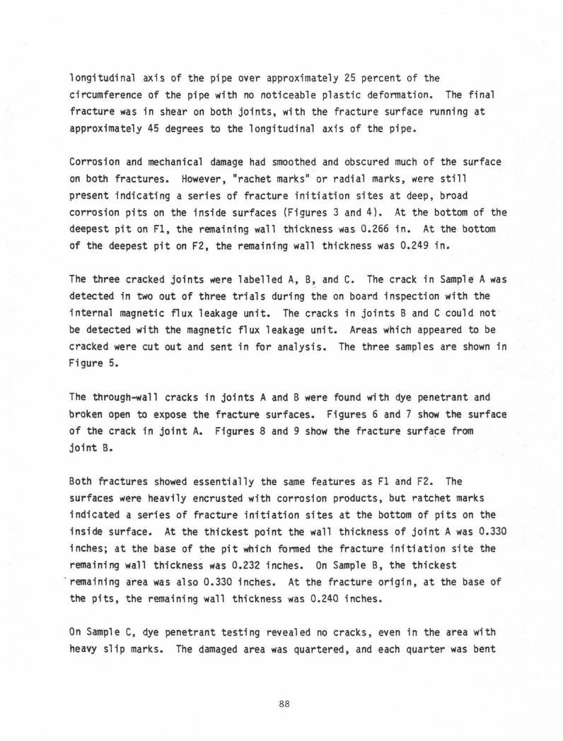
longitudinal axis of the pipe over approximately 25 percent of the
circumference of the pipe with no noticeable plastic deformation. The final
fracture was in shear on both joints, with the fracture surface running at
approximately 45 degrees to the longitudinal axis of the pipe.
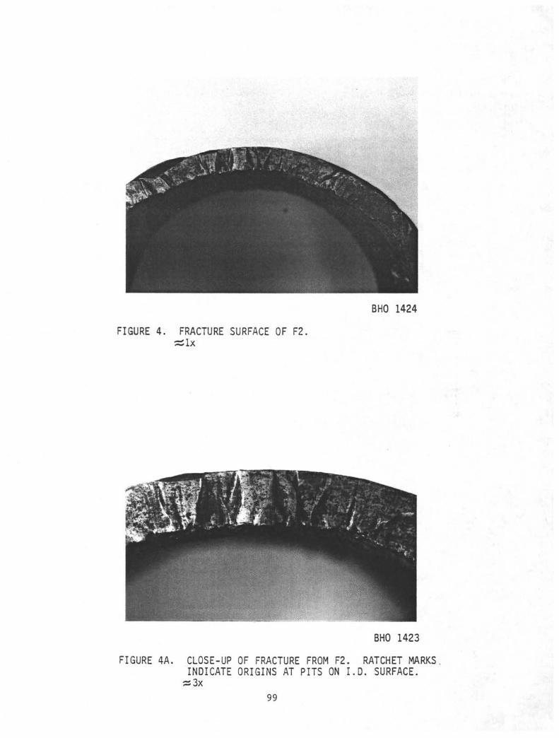
Corrosion and mechanical damage had smoothed and obscured much of the surface
on both fractures. However, "rachet marks" or radial marks, were still
present indicating a series of fracture initiation sites at deep, broad
corrosion pits on the inside surfaces (Figures 3 and 4). At the bottom of the
deepest pit on Fl, the remaining wall thickness was 0.266 in. At the bottom
of the deepest pit on F2, the remaining wall thickness was 0.249 in.
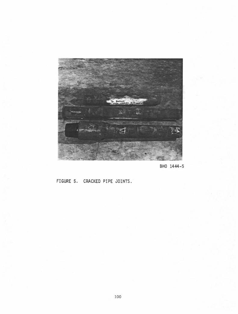
The three cracked joints were labelled A, B, and C. The crack in Sample A was
detected in two out of three trials during the on board inspection with the
internal magnetic flux leakage unit. The cracks in joints B and C could not
be detected with the magnetic flux leakage unit. Areas which appeared to be
cracked were cut out and sent in for analysis. The three samples are shown in
Figure 5.
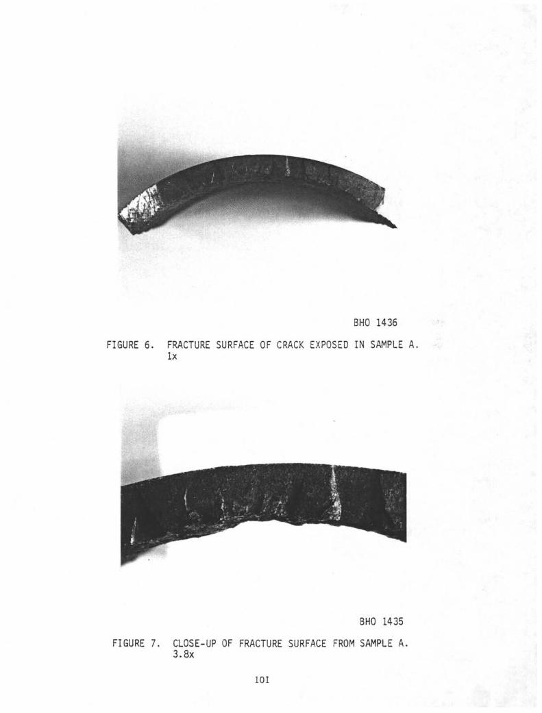
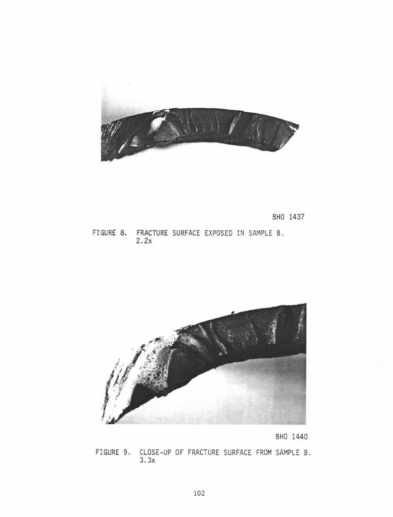
The through-wall cracks in joints A and B were found with dye penetrant and
broken open to expose the fracture surfaces. Figures 6 and 7 show the surface
of the crack in joint A. Figures 8 and 9 show the fracture surface from
joint B
Both fractures showed essentially the same features as Fl and F2. The
surfaces were heavily encrusted with corrosion products, but ratchet marks
indicated a series of fracture initiation sites at the bottom of pits on the
inside surface. At the thickest point the wall thickness of joint A was 0.330
inches; at the base of the pit which formed the fracture initiation site the
remaining wall thickness was 0.232 inches. On Sample B, the thickest
remaining area was also 0.330 inches. At the fracture origin, at the base of
the pits, the remaining wall thickness was 0.240 inches.
On Sample C, dye penetrant testing revealed no cracks, even in the area with
heavy slip marks. The damaged area was quartered, and each quarter was bent
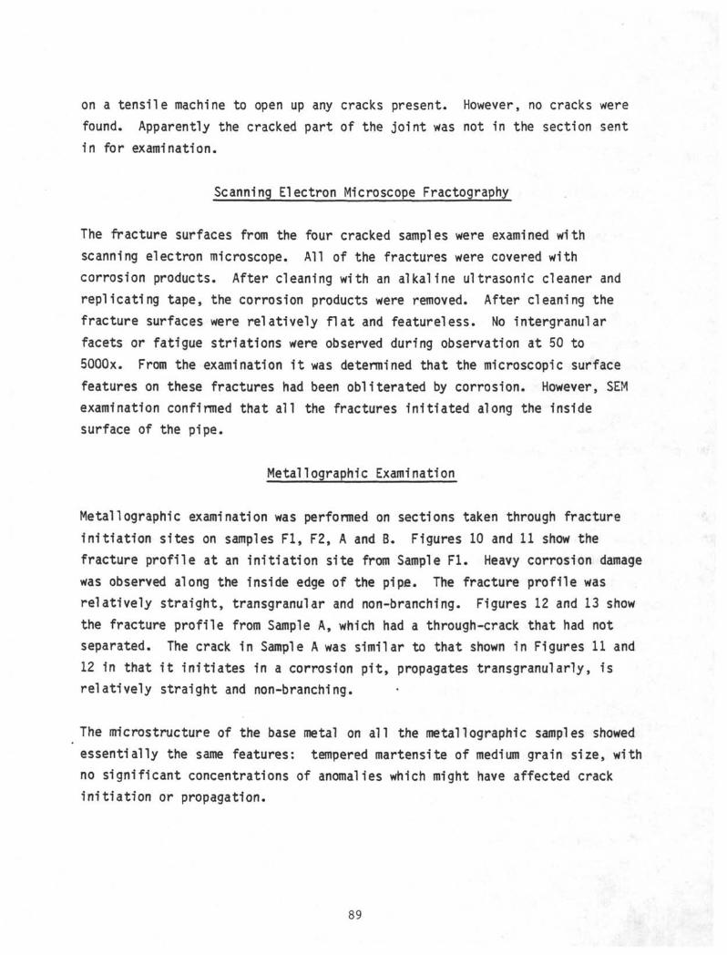
on a tensile machine to open up any cracks present. However, no cracks werefound. Apparently the cracked part of the joint was not in the section sentin for examination.
Scanning Electron Microscope Fractography
The fracture surfaces from the four cracked samples were examined withscanning electron microscope. All of the fractures were covered withcorrosion products. After cleaning with an alkaline ultrasonic cleaner andreplicating tape, the corrosion products were removed. After cleaning thefracture surfaces were relatively flat and featureless. No intergranularfacets or fatigue striations were observed during observation at 50 to5Q00x. From the examination it was determined that the microscopic surfacefeatures on these fractures had been obliterated by corrosion. However, SEMexamination confirmed that all the fractures initiated along the insidesurface of the pipe.
Metal!ographic Examination
Metallographic examination was performed on sections taken through fractureinitiation sites on samples Fl, F2, A and B. Figures 10 and 11 show thefracture profile at an initiation site from Sample Fl. Heavy corrosion damagewas observed along the inside edge of the pipe. The fracture profile wasrelatively straight, transgranular and non-branching. Figures 12 and 13 showthe fracture profile from Sample A, which had a through-crack that had notseparated. The crack in Sample A was similar to that shown in Figures 11 and12 in that it initiates in a corrosion pit, propagates transgranularly, isrelatively straight and non-branching.
The microstructure of the base metal on all the metallographic samples showedessentially the same features: tempered martensite of medium grain size, withno significant concentrations of anomalies which might have affected crackinitiation or propagation.
89
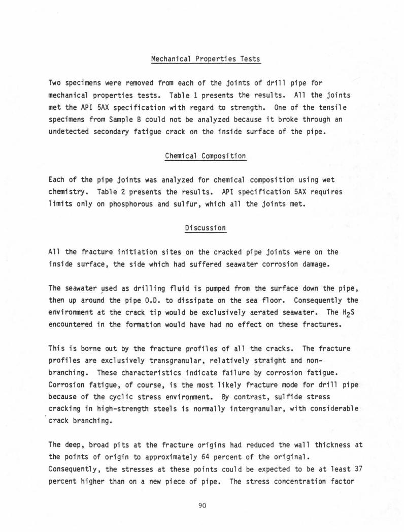
Mechanical Properties Tests
Two specimens were removed from each of the joints of drill pipe for
mechanical properties tests. Table 1 presents the results. All the joints
met the API 5AX specification with regard to strength. One of the tensile
specimens from Sample B could not be analyzed because it broke through an
undetected secondary fatigue crack on the inside surface of the pipe.
Chemical Composition
Each of the pipe joints was analyzed for chemical composition using wet
chemistry. Table 2 presents the results. API specification 5AX requires
limits only on phosphorous and sulfur, which all the joints met.
Discussion
All the fracture initiation sites on the cracked pipe joints were on the
inside surface, the side which had suffered seawater corrosion damage.
The seawater used as drilling fluid is pumped from the surface down the pipe,
then up around the pipe O.D. to dissipate on the sea floor. Consequently the
environment at the crack tip would be exclusively aerated seawater. The H£S
encountered in the formation would have had no effect on these fractures.
This is borne out by the fracture profiles of all the cracks. The fracture
profiles are exclusively transgranular, relatively straight and non-
branching. These characteristics indicate failure by corrosion fatigue.
Corrosion fatigue, of course, is the most likely fracture mode for drill pipe
because of the cyclic stress environment. By contrast, sulfide stress
cracking in high-strength steels is normally intergranular, with considerable
crack branching.
The deep, broad pits at the fracture origins had reduced the wall thickness at
the points of origin to approximately 64 percent of the original.
Consequently, the stresses at these points could be expected to be at least 37
percent higher than on a new piece of pipe. The stress concentration factor
90
from the pit geometry would make the effective stresses higher still.
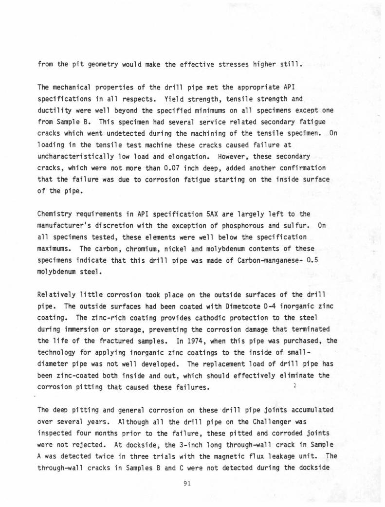
The mechanical properties of the drill pipe met the appropriate API
specifications in all respects. Yield strength, tensile strength and
ductility were well beyond the specified minimums on all specimens except one
from Sample B. This specimen had several service related secondary fatigue
cracks which went undetected during the machining of the tensile specimen. On
loading in the tensile test machine these cracks caused failure at
uncharacteristically low load and elongation. However, these secondary
cracks, which were not more than 0.07 inch deep, added another confirmation
that the failure was due to corrosion fatigue starting on the inside surface
of the pipe.
Chemistry requirements in API specification 5AX are largely left to the
manufacturers discretion with the exception of phosphorous and sulfur. On
all specimens tested, these elements were well below the specification
maximums. The carbon, chromium, nickel and molybdenum contents of these
specimens indicate that this drill pipe was made of Carbon-manganese- 0.5
molybdenum steel.
Relatively little corrosion took place on the outside surfaces of the drill
pipe. The outside surfaces had been coated with Dimetcote D-4 inorganic zinc
coating. The zinc-rich coating provides cathodic protection to the steel
during immersion or storage, preventing the corrosion damage that terminated
the life of the fractured samples. In 1974, when this pipe was purchased, the
technology for applying inorganic zinc coatings to the inside of small -
diameter pipe was not well developed. The replacement load of drill pipe has
been zinc-coated both inside and out, which should effectively eliminate the
corrosion pitting that caused these failures. «'
The deep pitting and general corrosion on these drill pipe joints accumulated
over several years. Although all the drill pipe on the Challenger was
inspected four months prior to the failure, these pitted and corroded joints
were not rejected. At dockside, the 3-inch long through-wall crack in Sample
A was detected twice in three trials with the magnetic flux leakage unit. The
through-wall cracks in Samples B and C were not detected during the dockside
91
examination, nor were any of the numerous secondary cracks in Sample B found
with the magnetic flux leakage unit.
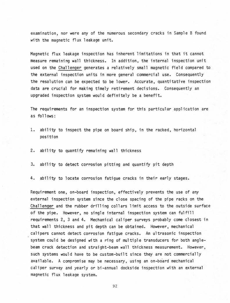
Magnetic flux leakage inspection has inherent limitations in that i t cannot
measure remaining wall thickness. In addition, the internal inspection unit
used on the Challenger generates a relatively small magnetic f ie ld compared to
the external inspection units in more general commercial use. Consequently
the resolution can be expected to be lower. Accurate, quantitative inspection
data are crucial for making timely retirement decisions. Consequently an
upgraded inspection system would definitely be a benefit.
The requirements for an inspection system for this particular application are
as follows:
1 . abi l i ty to inspect the pipe on board ship, in the racked, horizontal
position
2. abi l i ty to quantify remaining wall thickness
3. abi l i ty to detect corrosion pitt ing and quantify pit depth
4. abi l i ty to locate corrosion fatigue cracks in their early stages.
Requirement one, on-board inspection, effectively prevents the use of any
external inspection system since the close spacing of the pipe racks on the
Challenger and the rubber dr i l l ing collars l imit access to the outside surface
of the pipe. However, no single internal inspection system can f u l f i l l
requirements 2, 3 and 4. Mechanical caliper surveys probably come closest in
that wall thickness and pit depth can be obtained. However, mechanical
calipers cannot detect corrosion fatigue cracks. An ultrasonic inspection
system could be designed with a ring of multiple transducers for both angle-
beam crack detection and straight-beam wall thickness measurement. However,
such systems would have to be custom-built since they are not commercially
available. A compromise may be necessary, using an on-board mechanical
caliper survey and yearly or bi-annual dockside inspection with an external
magnetic flux leakage system.
92
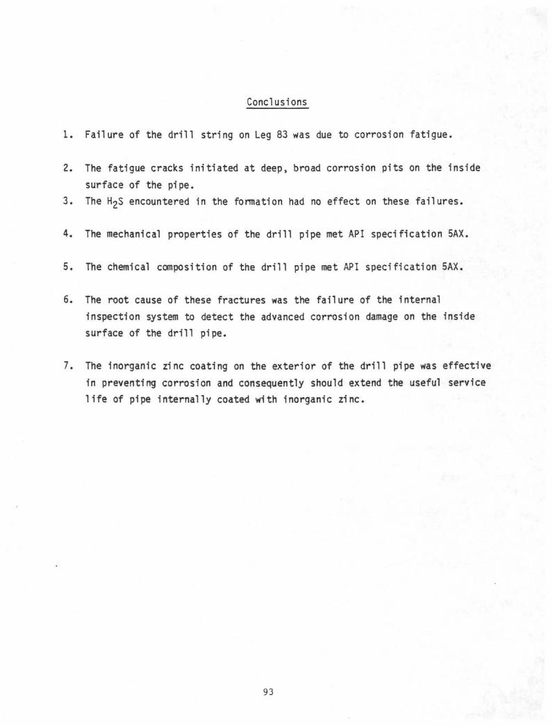
Conclusions
1. Failure of the drill string on Leg 83 was due to corrosion fatigue.
2. The fatigue cracks initiated at deep, broad corrosion pits on the inside
surface of the pipe.
3. The H£$ encountered in the formation had no effect on these failures.
4. The mechanical properties of the drill pipe met API specification 5AX.
5. The chemical composition of the drill pipe met API specification 5AX.
6. The root cause of these fractures was the failure of the internal
inspection system to detect the advanced corrosion damage on the inside
surface of the drill pipe.
7. The inorganic zinc coating on the exterior of the drill pipe was effective
in preventing corrosion and consequently should extend the useful service
life of pipe internally coated with inorganic zinc.
93
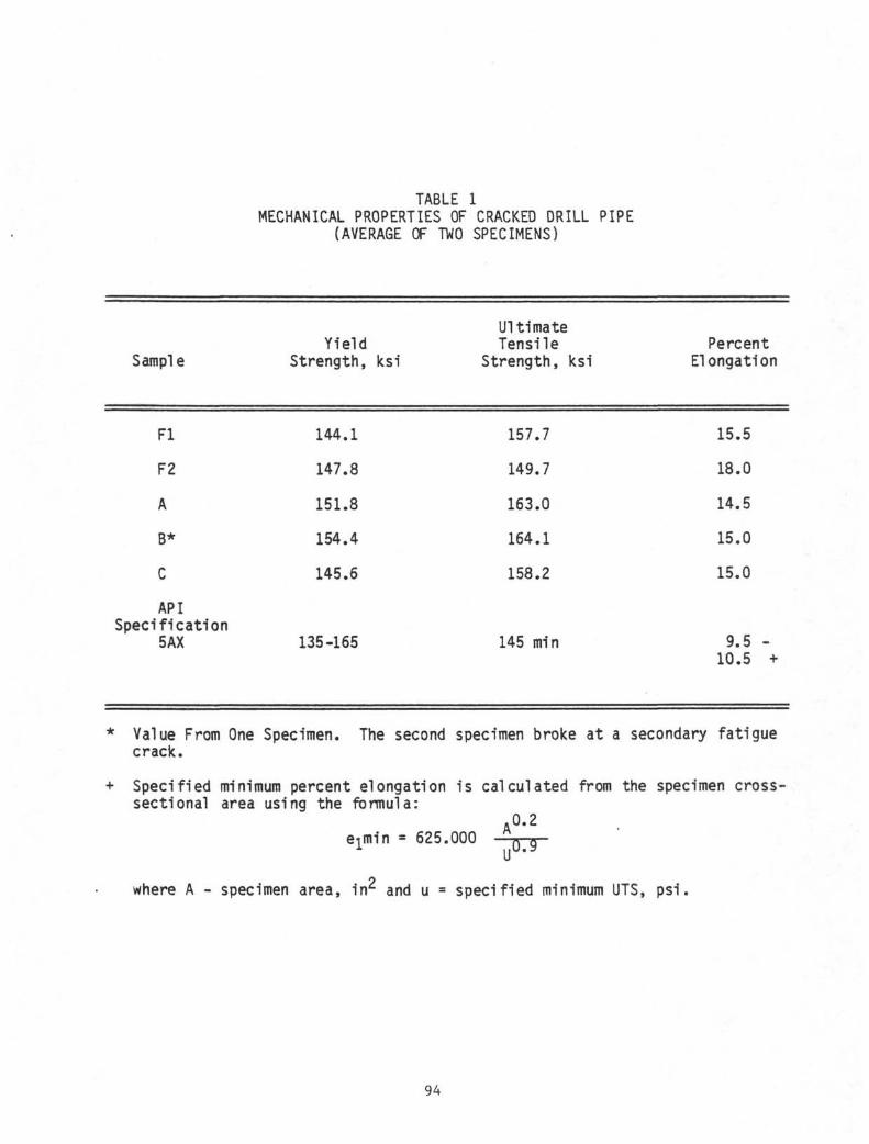
TABLE 1MECHANICAL PROPERTIES OF CRACKED DRILL PIPE
(AVERAGE OF TWO SPECIMENS)
Sample
Fl
F2
A
B*
C
APISpecification
5AX
YieldStrength, ksi
144.1
147.8
151.8
154.4
145.6
135-165
UltimateTensile
Strength, ksi
157.7
149.7
163.0
164.1
158.2
145 min
PercentElongation
15.5
18.0
14.5
15.0
15.0
9.5 -10.5 +
* Value From One Specimen. The second specimen broke at a secondary fatiguecrack.
+ Specified minimum percent elongation is calculated from the specimen cross-sectional area using the formula:
A0'2
eimin « 625.000 * Q
U
where A - specimen area, in^ and u = specified minimum UTS, psi.
94
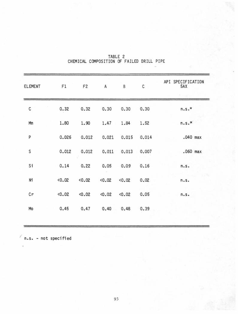
TABLE 2CHEMICAL COMPOSITION OF FAILED DRILL PIPE
API SPECIFICATIONELEMENT F l F2 A B C 5AX
C 0.32 0.32 0.30 0.30 0.30 n.s.*
Mn 1.80 1.90 1.47 1.84 1.52 n .s . *
P 0.026 0.012 0.021 0.015 0.014 .040 max
S 0.012 0.012 0.011 0.013 0.007 .060 max
Si 0.14 0.22 0.05 0.09 0.16 n.s.
Ni <0.02 <0.02 <0.02 <0.02 0.02 n.s.
Cr <0.02 O.02 <0.02 <0.02 0.05 n.s.
Mo 0.45 0.47 0.40 0.48 0.39
n.s. - not specified
95
WATER SAMPLE: 80 C + H2S
TOP FISH #1
WATER SAMPLE:115 C + H2S
TOTAL DEPTH FISH #1
TOP FISH #2
C3
TOTAL DEPTH FISH #2
co
MUDLINE 3473 METERS
BASEMENT CONTACT 3743 METERS
3948 METERS
4048 METERS
4263 METERS
— OLD HOLE TO 4307 METERS
4335 METERS
4399 METERS
4535 METERS4543 METERS
TOTAL DEPTH 12/15/81: 4761 METERS
FIGURE 1. Schematic of DSDP Hole 504B.
96
BHO 1444-1
FIGURE 2. FRACTURED PIECES OF DRILL PIPE. (NOTE:WHITE SUBSTANCE ON F-2 BOX END FRACTUREIS SILICONE RUBBER FOR PROTECTING THEFRACTURE SURFACE) ,
97
BHO 142 2
FIGURE 3. FRACTURE SURFACE OF F 1 .l×
FIGURE 3A. CLOSE-UP OF FRACTURE FROM F 1.MARKS INDICATE ORIGINS ON I . 03x
SHO 1421
RATCHETSURFACE.
98
BHO 1424
FIGURE 4. FRACTURE SURFACE OF F2.sslx
BHO 1423
FIGURE 4A. CLOSE-UP OF FRACTURE FROM F2. RATCHET MARKSINDICATE ORIGINS AT PITS ON I.D. SURFACE.3x
99
BHO 1444-5
FIGURE 5. CRACKED PIPE JOINTS
100
BHO 1436
FIGURE 6. FRACTURE SURFACE OF CRACK EXPOSED IN SAMPLE A,lx
BHO 1435
FIGURE 7. CLOSE-UP OF FRACTURE SURFACE FROM SAMPLE A.3 .8x
101
BHO 1437
FIGURE 8. FRACTURE SURFACE EXPOSED IN SAMPLE B.2.2x
BHO 1440
FIGURE 9. CLOSE-UP OF FRACTURE SURFACE FROM SAMPLE B3.3x
102
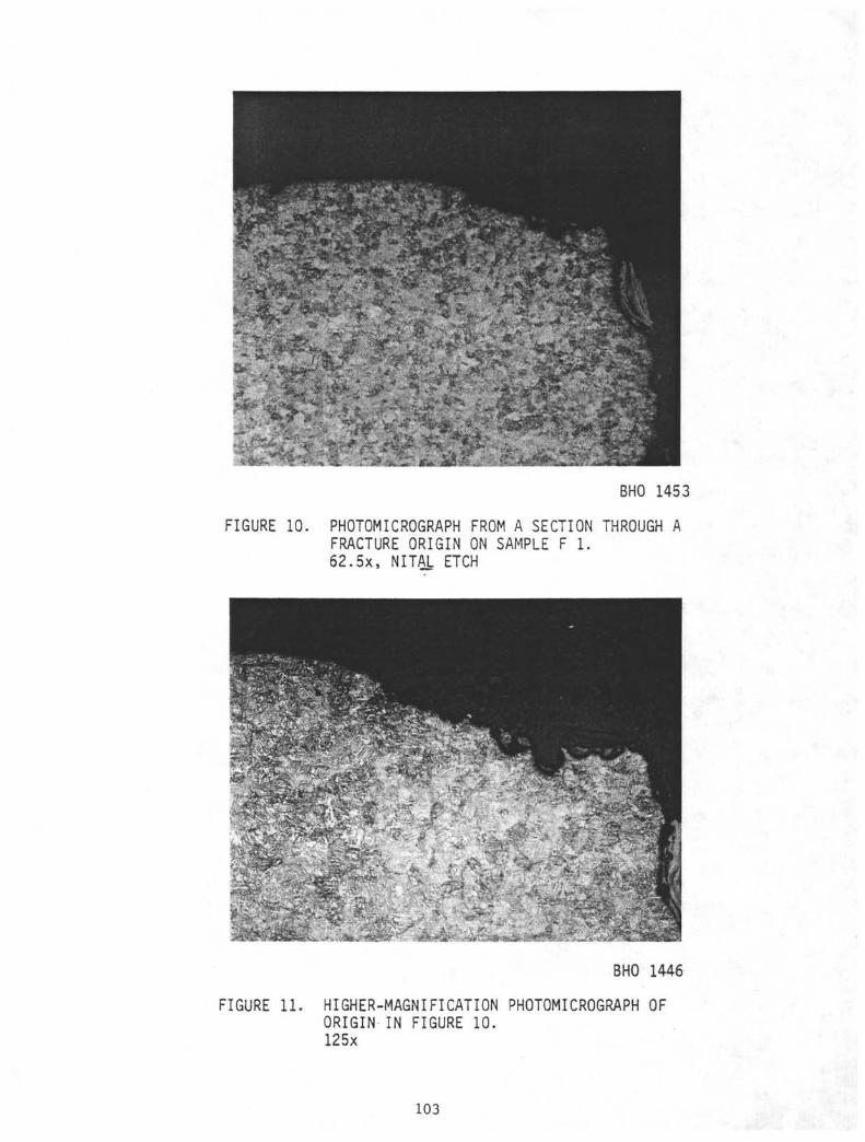
BHO 1453
FIGURE 10. PHOTOMICROGRAPH FROM A SECTION THROUGH AFRACTURE ORIGIN ON SAMPLE F 1.62.5x, NITAL ETCH
BHO 1446
FIGURE 11. HIGHER-MAGNIFICATION PHOTOMICROGRAPH OFORIGIN IN FIGURE 10.125x
103
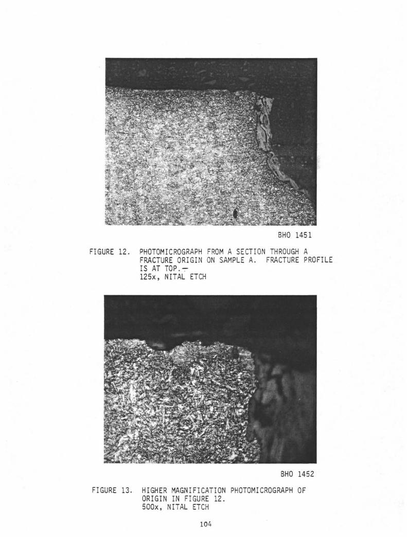
BHO 1451
FIGURE 12. PHOTOMICROGRAPH FROM A SECTION THROUGH AFRACTURE ORIGIN ON SAMPLE A. FRACTURE PROFILEIS AT TOP.r125x, NITAL ETCH
BHO 1452
FIGURE 13. HIGHER MAGNIFICATION PHOTOMICROGRAPH OFORIGIN IN FIGURE 12.5OOx, NITAL ETCH
104
APPENDIX B-4
FINAL REPORTFAILURE OF DRILL STRING
DSDP LEG 84
OßatteiieHouston Operations2223 West Loop South
•-i , Λ O O Suite 320A p r i l 2 6 , 1982 Houston, Texas 77027
Telephone (713) 877-8034
Re: F a i l u r e of D r i l l S t r i n g , DSDP Leg 84 Contract No. G 12696-3058
Enclosed are f i v e copies of B a t t e l l e ' s report on the f a i l u r e of the d r i l l
s t r i n g , DSDP Leg 84. This report c o n s t i t u t e s f u l f i l l m e n t of the April 3 0 ,
1982, reporting requirement of Contract G 12696-3058.
FINAL REPORT
FAILURE OF DRILL STRING; DSDP LEG 84
SUMMARY
Excessive strength and hardness led to hydrogen embrittlement cracking of the
f a i l e d j o i n t of a 5-inch O.D., 19.5 l b / f t S-135 d r i l l pipe (DSDP
i d e n t i f i c a t i o n number DP-568-7-2-82). Crack i n i t i a t i o n was accelerated by the
presence of a 1.5 inch by 0.045 inch deep l a p , a r o l l e d - i n m i l l d e f e c t . The
hydrogen which caused the embrittlement was generated by corrosion of the
pipe's s a c r i f i c i a l zinc coating in sea water. Any remaining j o i n t s from t h i s
order of pipe should be hardness t e s t e d . Joints with hardness exceeding RC38
should not be used.
107
Deep Sea Drilling Project April 26, 1982
BACKGROUND
On February 7, 1982, during logging operations at DSDP 567A, the d r i l l string
parted in the 18th jo in t below the r ig f loor . The fai led jo in t was 5-inch
O.D., 19.5 l b / f t S-135 pipe which had been internal ly and externally coated
with inorganic zinc. The fai led piece was one of 667 30-ft jo ints of S-135
d r i l l pipe made by Jones and Laugh!in's Youngstown mil l in two different lots
in June and September of 1977 for DSDP. Jones and Laughlin heat numbers for
th is order were 26638, 24132, 27846, 25995 (June 1977) and 32549, 27168, 27170
(September, 1977). The fai led jo in t was loaded on the GLOMAR CHALLENGER on
November 3, 1979 at Balboa, Panama. I t remained in the 'tween-decks hold of
the d r i l l ship unt i l January 16th, 1982. The jo in t had spent about 8 1/2 days
deployed in the d r i l l string with approximately 67 total rotating hours.
Weather conditions assured bending stresses had been at a minimum. String
weight at the fa i lure was estimated to be 370,000 pounds which equates to a
tensile stress level of approximately-70,100 psi . This value is only 52
percent of the API specified minimum yield strength (SMYS) of 135,000 ps i .
A four foot section of the fai led pipe j o i n t , see Figure 1, was received at
the Battelle laboratories at the end of March.
VISUAL EXAMINATION
Visual examination revealed a f l a t , b r i t t l e fracture which originated at a lap
and propagated approximately 90 degrees around the pipe circumference. The
fracture mode then changed to shear overload, evidenced by a 45 degree
orientation fracture face, (Figure 2-4).
Mechanical and Chemical Properties
A section of the fai led pipe jo int was used to determine the mechanical and
chemical properties, see Tables 1 and 2. The yield strength was found to be
higher than allowed in API Specification 5AX. Microhardness readings, which
were taken across a mounted specimen, ranged in value from Knoop hardness 100
kg number 386 to 477, see Figure 5. These numbers roughly correspond to
Rockwell hardness numbers in the Rc 40-45 range. The mechanical properties
108
Deep Sea Drilling Project April 26, 1982
obtained by Battelle indicate higher strength levels than the reported mil l
values, see Table 1.
Chemical properties are given in Table 2. The composition of this pipe jo in t
meets that required in API specification 5AX.
SEM Fractography
The fracture origin was examined in the scanning electron microscope (SEM).
Region 2 (Figure 6) shows the origin at 11X; the chevron marks pointing
towards the point of fracture in i t ia t ion are clearly evident. Higher
magnification of this region reveals intergranular fracture , Figure 7. The
f l a t , b r i t t l e part of the fracture was exclusively intergranular cracking,
with no evidence of fatigue str iat ions. In the shear l i p , the fracture mode
switched to dimpled rupture.
Optical Metallography
The fracture was next sectioned and mounted to closely examine cross-sections
of the origin and lap. Etching revealed the material microstructure was
quenched and tempered martensite, as is expected for quenched and tempered
S-135 pipe. The cross section through the origin (Section A-A) confirmed that
the fracture mode was intergranular, Figure 8. Deformation was seen in grains
near the surface, see Figure 9. This deformation was most l i ke ly caused after
the fa i lure. There was no evidence of high-temperature oxide on the fracture
surface or in the crack branches.
The lap (Section B-B) was found to be f i l l e d with oxide. The region direct ly
adjacent to the lap surface was decarburized (See Figure 10). These fractures
indicate the lap was formed during the rol l ing process in the m i l l .
DISCUSSION
The d r i l l pipe fai lure shows all the elements of hydrogen embrittlement-
cracking. Hydrogen embrittlement cracking is a form of stress corrosion
cracking in which corrosion-generated hydrogen diffuses into the steel and
109
Deep Sea Dr i l l ing Project April 26, 1982
causes embrittlement, resulting in cracking at stresses well below the tensile
yield strength.
The high strength and hardness of this jo in t of d r i l l pipe rendered i t
particularly susceptible to hydrogen embrittlement-cracking. High strength
low alloy steels become increasingly sensitive to hydrogen embrittlement-
cracking as the strength is increased. Practically speaking such failures are
rarely observed in sea water i f the ultimate tensile strength of the material
is less than about 180 ksi . This is one reason for the 165 ksi maximum yield
strength requirement in API specification 5AX.
The lap in the surface was apparently introduced during the tube rol l ing
operation, since there was a thin decarburized zone on i ts faces. This is
typical of mil l defects which occur during hot-ro l l ing. The lap served as a
stress raiser causing locally high stresses. API 5AX specification allows
imperfections such as this lap as long as they do not exceed 12.5 percent of
the nominal wall thickness, which in this case would be 0.045 inch in depth.
The deepest measured depth of the lap was 0.045 i n . Therefore, this lap was
rejectable according to API 5AX.
The source of the hydrogen was the corrosion of the sacr i f ic ia l zinc coating
on the pipe. As the zinc corrodes, hydrogen is evolved at the cathode, which
in this case would be any exposed steel. Zinc-rich coatings are a standard
corrosion prevention method in sea water and marine atmospheres; earl ier
strings of zinc coated S-135 (with lower hardness levels) gave up to seven
years1 service on the DSDP before fa i l ing by corrosion pi t t ing on the uncoated
inside of the pipe. However, in addition to the corrosion protection, zinc
coating also greatly increases the amount of hydrogen being absorbed into the
steel. If the pipe's hardness and strength are excessive, thus making i t
susceptible to hydrogen embrittlement-cracking, a zinc coating wi l l cause
rapid and catastrophic cracking, see Figure l l . 1 ' ^ ' ^
Since other pipe joints from this same order may have the same high stregnth,
al l joints from this order are suspect. Any joints le f t from this order
should not be used unless their strength has been tested and confirmed to fa l l
110
Deep Sea Drilling Project April 26, 1982
within the API specification range. Direct strength evaluations, however,
require destructive testing.
I t is more practical to estimate the strength of d r i l l pipe in the f ie ld by
hardness testing. Hardness correlates well with ultimate tensile strength,
and the ultimate tensile strength can be used to predict the yield strength.
Analysis of mechanical properties data from f i f t y samples of S-135 d r i l l pipe
indicates that the yield strength averages 92 percent of the ultimate tensile
strength, with a range of from 86 to 94 percent. This would indicate that, at
the upper yield strength l imi t of 165 ks i , ultimate tensile strengths of from
175 to 191 ksi can be expected. High-strength low alloy steels with ultimate
tensile strengths of 175 ksi wi l l have hardnesses of approximately Rc 38.5.
Therefore, any pipe joints with hardness in excess of RC38 should be rejected.
CONCLUSIONS
1) The strength of the failed d r i l l pipe exceeded the API 5AX
specification, making i t unusually susceptible to hydrogen
embrittlement
2) The fracture ini t iated at a lap, a rol led-in mill defect which
was rejectable by the API 5AX specification. The presence of
the lap caused locally high stresses and therefore accelerated
crack in i t ia t ion
3) The fracture mode was intergranular, indicating fai lure by
hydrogen embrittlement
4) The hydrogen which caused the cracking came from corrosion of
the sacr i f ic ia l zinc-rich coating on the pipe. However, the
zinc-rich coating should be safe to use i f the strength of the
pipe is kept within specification
5) Any remaining pieces of d r i l l pipe from this order should be
tested for hardness. Any pieces whose hardness exceeds RC38
should be discarded to prevent a recurrence of this kind of
fa i lure.
i l l
Deep Sea Drilling Project April 26, 1982
If you have any questions concerning this report, please contact us at (713)
877-8034. It was a pleasure working with DSDP again; thank you for contacting
Battelle.
Very truly yours,
Beverlee G. SteinbergResearch Scientist
Dale R. MclntyrePrincipal Research Scientist
112
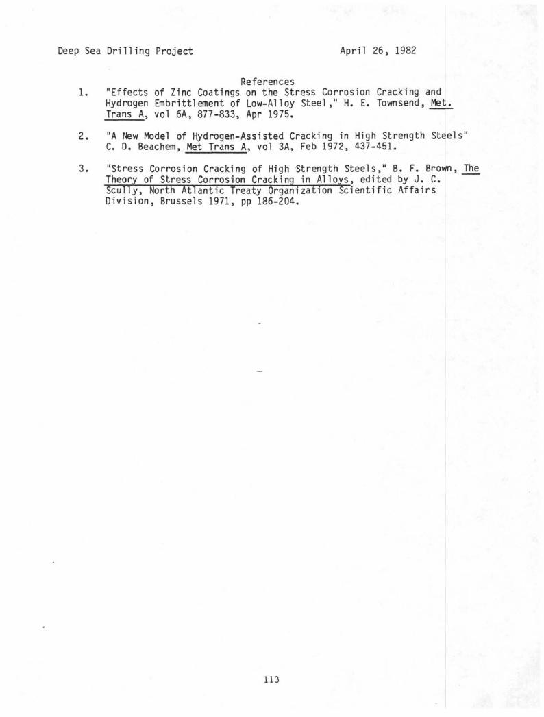
Deep Sea Drilling Project Apr i l 26, 1982
References1. "Effects of Zinc Coatings on the Stress Corrosion Cracking and
Hydrogen Embrittlement of Low-Alloy Stee l , " H. E. Town send, Met.Trans A, vol 6A, 877-833, Apr 1975.
2. "A New Model of Hydrogen-Assisted Cracking in High Strength Steels"C. D. Beachem, Met Trans A, vol 3A, Feb 1972, 437-451.
3. "Stress Corrosion Cracking of High Strength Steels," B. F. Brown, TheTheory of Stress Corrosion Cracking in A l loys, edited by J . C.Scul ly, North At lant ic Treaty Organization Sc ien t i f i c A f fa i rsD iv i s ion , Brussels 1971, pp 186-204.
113
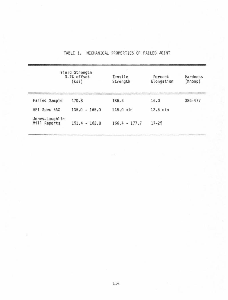
TABLE 1. MECHANICAL PROPERTIES OF FAILED JOINT
Failed
API SD<
Yield Strength0.7% offset
(ksi)
Sample 170.8
ic 5AX 135.0 - 165.0
TensileStrength
186.3
145.0 min
PercentElongation
16.0
12.5 min
Hardness(Knoop)
386-477
Jones-Laugh!inMill Reports 151.4 - 162.8 166.4 - 177.7 17-25
114
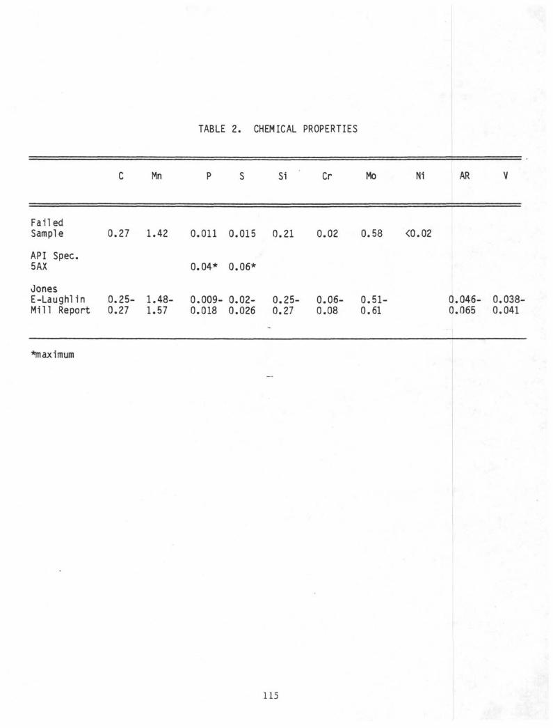
TABLE 2. CHEMICAL PROPERTIES
Mn Si Cr Mo Ni AR
FailedSample
API Spec.5AX
JonesE-LaughlinMill Report
0.27 1.42 0.011 0.015 0.21 0.02 0.58 <0.02
0.25- 1.48-0.27 1.57
0.04* 0.06*
0.009- 0.02-0.018 0.026
0.25-0.27
0.06-0.08
0.51-0.61
0.046- 0.038-0.065 0.041
*maximum
115
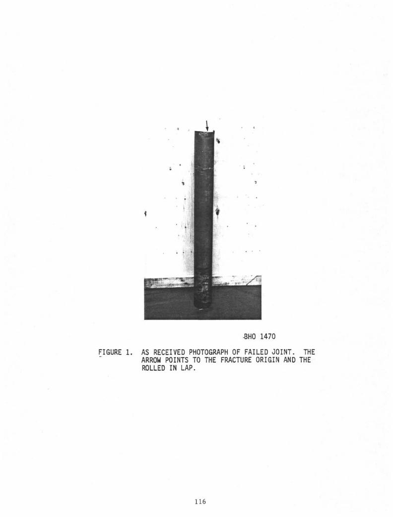
-BHO 1470
FIGURE 1. AS RECEIVED PHOTOGRAPH OF FAILED JOINT. THEARROW POINTS TO THE FRACTURE ORIGIN AND THEROLLED IN LAP.
116
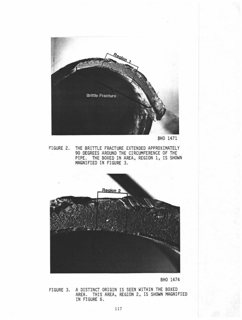
BHO 1471
FIGURE 2. THE BRITTLE FRACTURE EXTENDED APPROXIMATELY90 DEGREES AROUND THE CIRCUMFERENCE OF THEPIPE. THE BOXED IN AREA, REGION 1, IS SHOWNMAGNIFIED IN FIGURE 3.
BHO 1474
FIGURE 3. A DISTINCT ORIGIN IS SEEN WITHIN THE BOXEDAREA. THIS AREA, REGION 2, IS SHOWN MAGNIFIEDIN FIGURE 6.
117
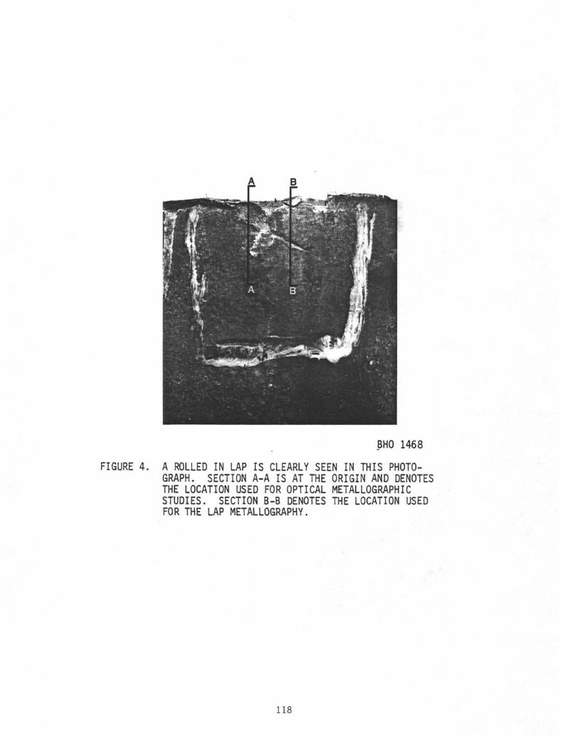
BHO 1468
FIGURE 4. A ROLLED IN LAP IS CLEARLY SEEN IN THIS PHOTO-GRAPH. SECTION A-A IS AT THE ORIGIN AND DENOTESTHE LOCATION USED FOR OPTICAL METALLOGRAPHICSTUDIES. SECTION B-B DENOTES THE LOCATION USEDFOR THE LAP METALLOGRAPHY.
118
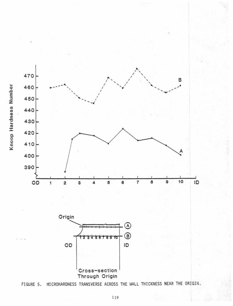
/\
nεz<oΦcCS
Iαooc
470
460
450
440
430
420
410
400
390
B
OD 6 8
Origin
OD ID
10 ID
FIGURE 5.
Cross-sectionThrough Origin
MICROHARDNESS TRANSVERSE ACROSS THE WALL THICKNESS NEAR THE ORIGIN
119
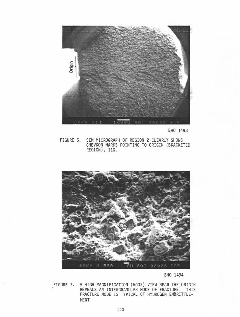
BHO 1493
FIGURE 6. SEM MICROGRAPH OF REGION 2 CLEARLY SHOWSCHEVRON MARKS POINTING TO ORIGIN (BRACKETEDREGION), 11X.
.BHO 1494
FIGURE 7. A HIGH MAGNIFICATION (500X) VIEW NEAR THE ORIGINREVEALS AN INTERGRANULAR MODE OF FRACTURE. THISFRACTURE MODE IS TYPICAL OF HYDROGEN EMBRITTLE-MENT.
120
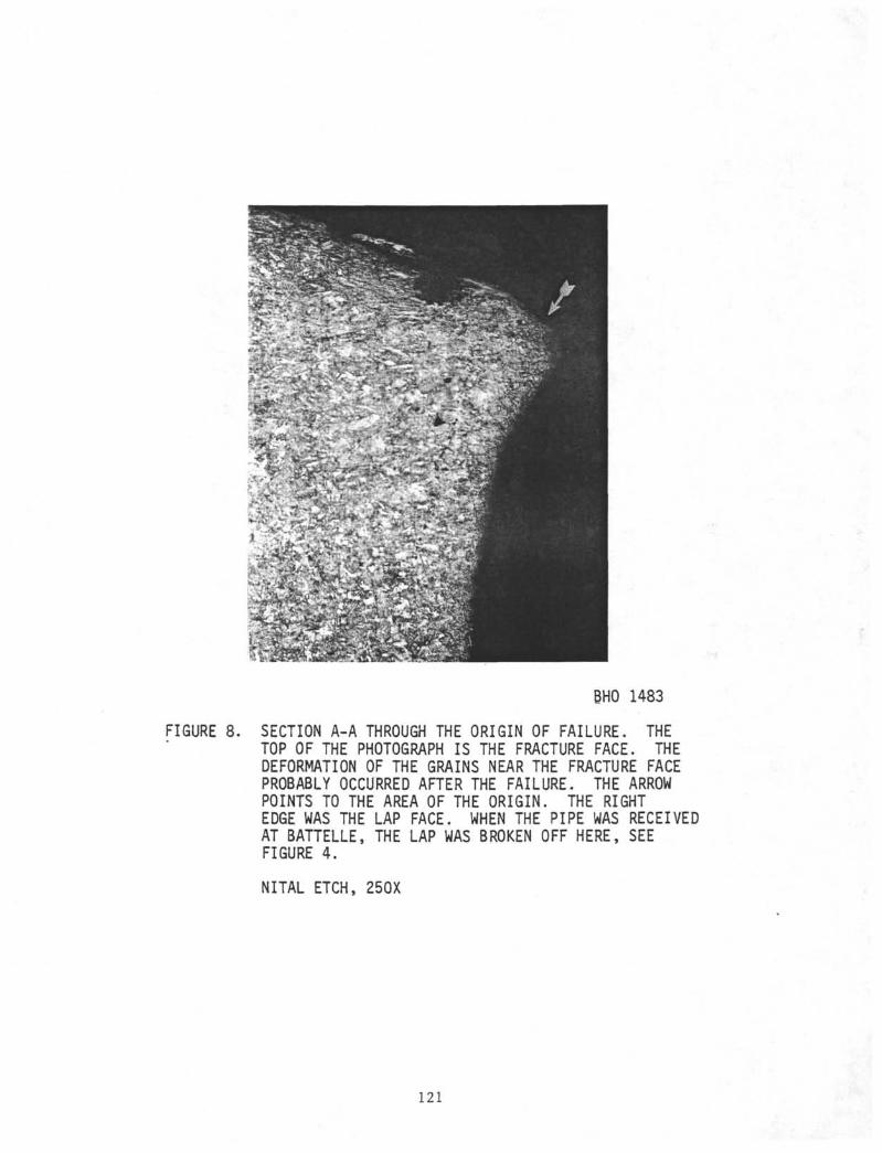
BHO 1483
FIGURE 8. SECTION A-A THROUGH THE ORIGIN OF FAILURE. THETOP OF THE PHOTOGRAPH IS THE FRACTURE FACE. THEDEFORMATION OF THE GRAINS NEAR THE FRACTURE FACEPROBABLY OCCURRED AFTER THE FAILURE. THE ARROWPOINTS TO THE AREA OF THE ORIGIN. THE RIGHTEDGE WAS THE LAP FACE. WHEN THE PIPE WAS RECEIVEDAT BATTELLE, THE LAP WAS BROKEN OFF HERE, SEEFIGURE 4.
NITAL ETCH, 25OX
121
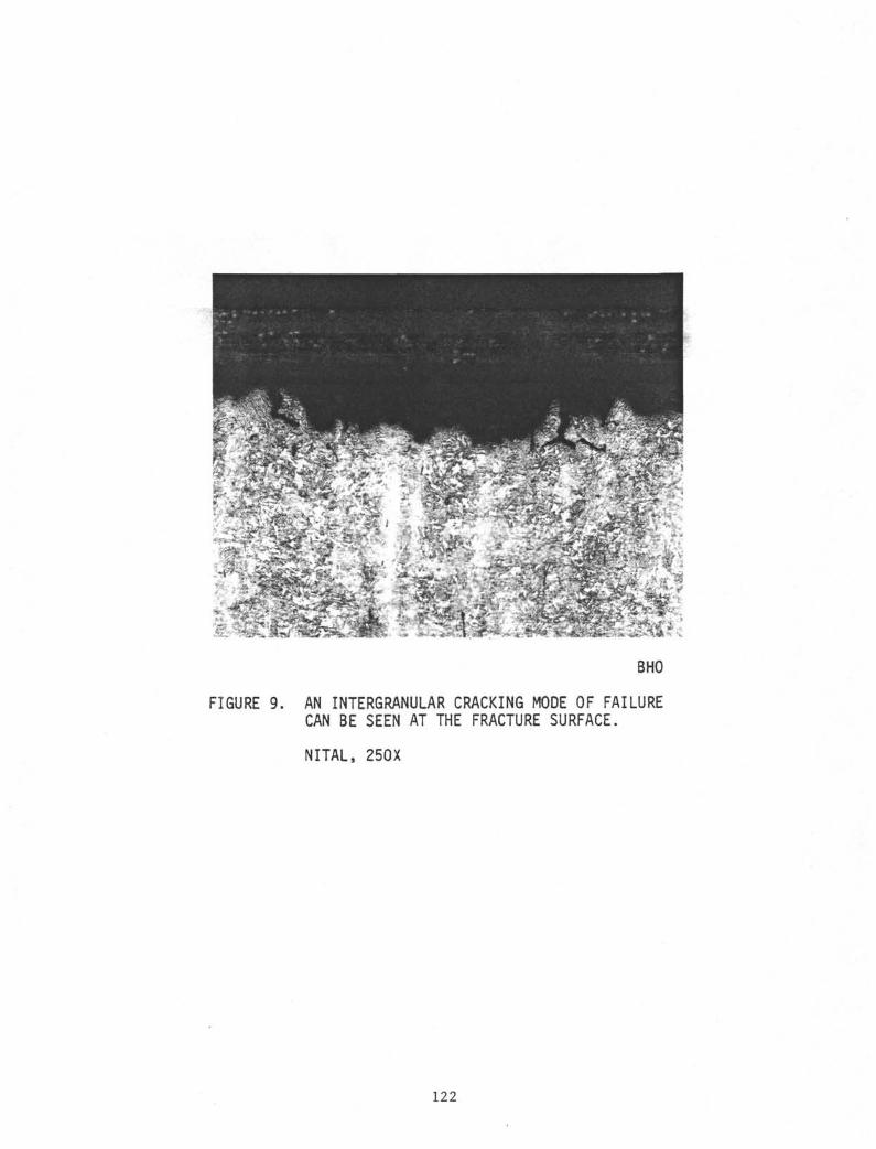
• _..._
FIGURE 9.
BHO
AN INTERGRANULAR CRACKING MODE OF FAILURECAN BE SEEN AT THE FRACTURE SURFACE.
NITAL, 25OX
122
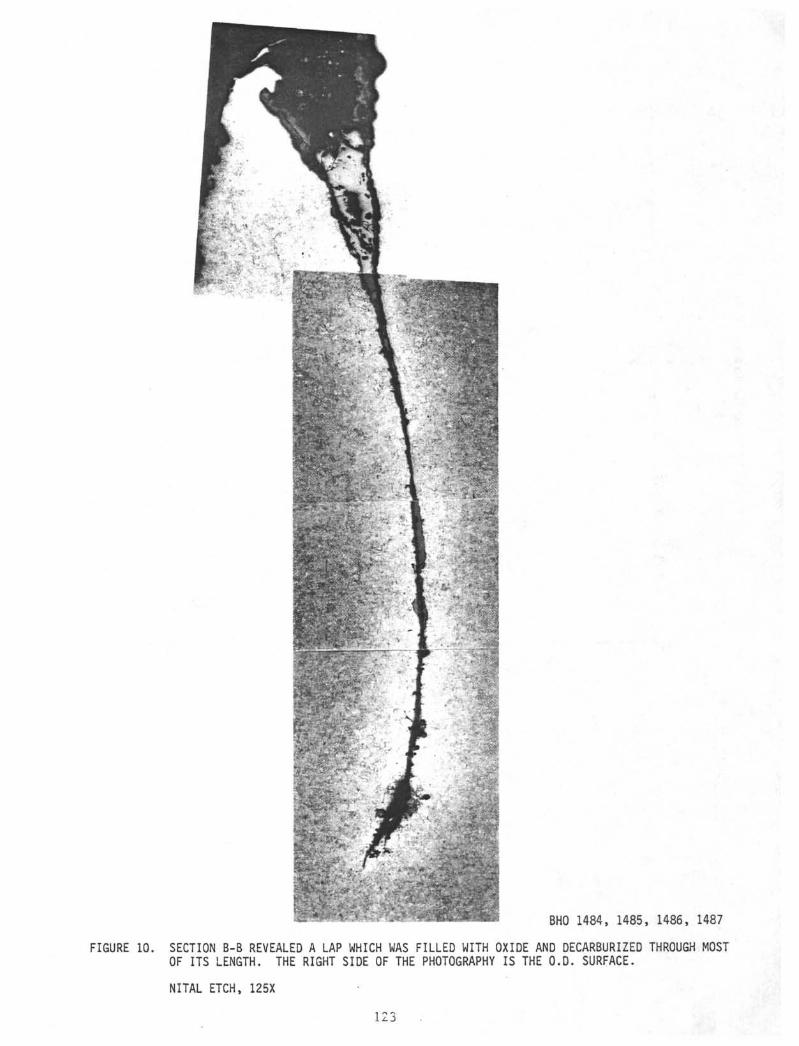
BHO 1484, 1485, 1486, 1487
FIGURE 10. SECTION B-B REVEALED A LAP WHICH WAS FILLED WITH OXIDE AND DECARBURIZED THROUGH MOSTOF ITS LENGTH. THE RIGHT SIDE OF THE PHOTOGRAPHY IS THE O.D. SURFACE.
NITAL ETCH, 125X
123
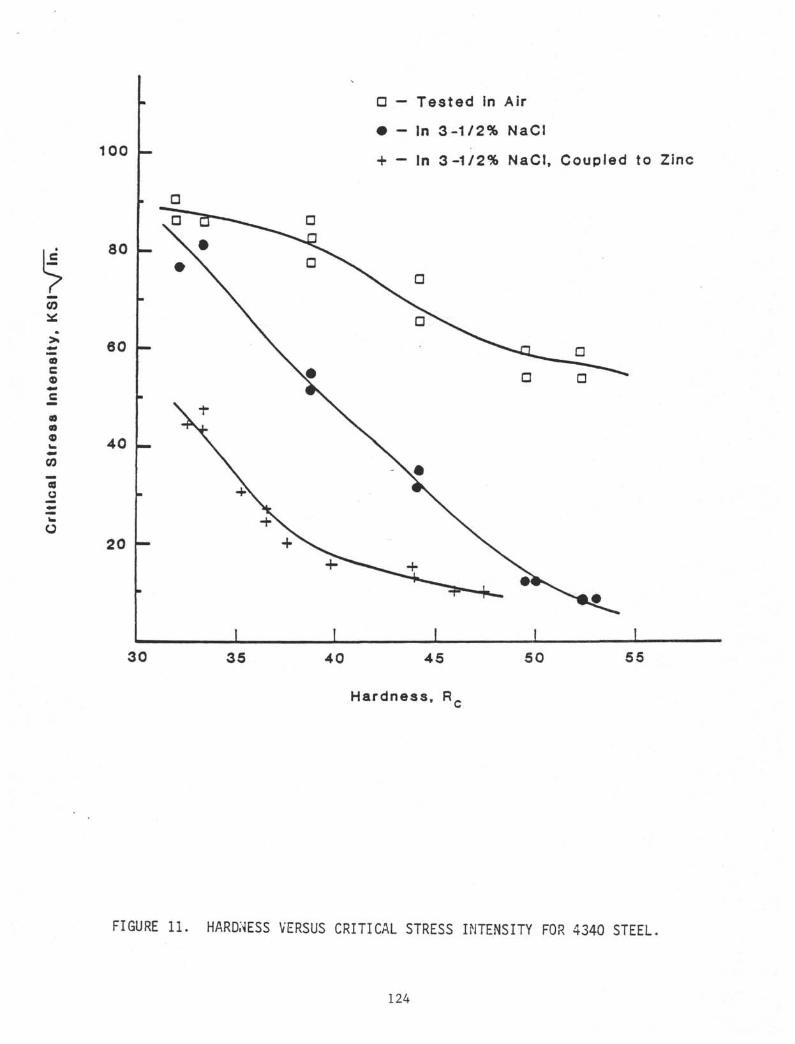
CO
100
8 0
6 0
4 0
2 0
αTo 3 — —
•M•
|
m T
\
>
G — Tested in
• - In 3-1/2%
+ - In 3-1/2%
Air
NaCI
NaCI,
α
•
j
Coupled to Zinc
G
3 0 35 4 0 4 5 5 0 55
Hardness, R
FIGURE 11. HARDNESS VERSUS CRITICAL STRESS INTENSITY FOR 4340 STEEL
124
APPENDIX B-5
FAILURE ANALYSIS OF KELLY COCK SUB(LEG 93)
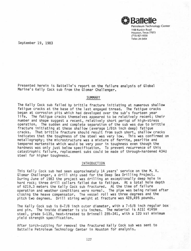
l l B tteiiePetroleum Technology Center1100 Rankin RoadHouston, Texas 77073(713) 821-9330Telex 24-5454
September 19, 1983
Presented herein is Battel le 's report on the fa i lure analysis of GlobalMarine1s Kelly Cock sub from the Glomar Challenger.
SUMMARY
The Kelly Cock sub fai led by b r i t t l e fracture in i t i a t i ng at numerous shallowfatigue cracks at the base of the last engaged thread. The fatigue cracksbegan at corrosion pits which had developed over the sub's fourteen yearl i f e . The fatigue cracks themselves appeared to be relat ively recent; thei rnumber and shape suggest a recent, relat ively short period of high-stressoperation. The sudden and complete separation of the sub was due to b r i t t l efracture i n i t i a t i ng at these shallow (average l /8th inch deep) fatiguecracks. That b r i t t l e fracture should result from such short, shallow cracksindicates that the toughness of the steel was very low. This was confirmed onmetallography; the microstructure was a mixture of f e r r i t e , pearlite andtempered martensite which would be very poor in toughness even though thehardness was only just below specif ication. To prevent recurrence of th iscatastrophic fa i lu re , replacement subs could be made of through-hardened 4340steel for higher toughness.
INTRODUCTION
This Kelly Cock sub had seen approximately 14 years1 service on the M. V.Glomar Challenger, a d r i l l ship used for the Deep Sea Dr i l l i ng Project.During June of 1983 the project was d r i l l i ng an exceptionally deep hole inhard rock; three d r i l l collars fai led due to fatigue. At a total hole depthof 6219.3 meters the Kelly Cock sub fractured. At the time of fa i lureoperation and weather conditions were normal. The pipe was being raised afterclosing the heave compensator. The vessel ro l l was three degrees and thepitch two degrees. Dr i l l str ing weight at fracture was 428,495 pounds.
The Kelly Cock sub is 8-7/8 inch outer diameter, with a 7-5/8 inch regular boxand pin. The inside diameter is six inches. The material is AISI 4145Hsteel , grade S-135, heat-treated to Brinnell 285-341, with a 120 ksi minimumyield strength specif icat ion.
After torch-cutting for removal the fractured Kelly Cock sub was sent toBattelle Petroleum Technology Center in Houston for analysis.
127
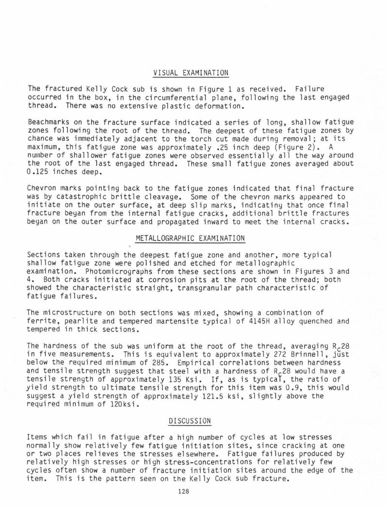
VISUAL EXAMINATION
The fractured Kelly Cock sub is shown in Figure 1 as received. Failureoccurred in the box, in the circumferential plane, following the last engagedthread. There was no extensive plastic deformation.
Beachmarks on the fracture surface indicated a series of long, shallow fatiguezones following the root of the thread. The deepest of these fatigue zones bychance was immediately adjacent to the torch cut made during removal ; at itsmaximum, this fatigue zone was approximately .25 inch deep (Figure 2 ) . Anumber of shallower fatigue zones were observed essentially all the way aroundthe root of the last engaged thread. These small fatigue zones averaged about0.125 inches deep.
Chevron marks pointing back to the fatigue zones indicated that final fracturewas by catastrophic brittle cleavage. Some of the chevron marks appeared toinitiate on the outer surface, at deep slip marks, indicating that once finalfracture began from the internal fatigue cracks, additional brittle fracturesbegan on the outer surface and propagated inward to meet the internal cracks.
METALLOGRAPHIC EXAMINATION
Sections taken through the deepest fatigue zone and another, more typicalshallow fatigue zone were polished and etched for metallographicexamination. Photomicrographs from these sections are shown in Figures 3 and4. Both cracks initiated at corrosion pits at the root of the thread; bothshowed the characteristic straight, transgranular path characteristic offatigue failures.
The microstructure on both sections was mixed, showing a combination offerrite, pearlite and tempered martensite typical of 4145H alloy quenched andtempered in thick sections.
The hardness of the sub was uniform at the root of the thread, averaging RC28in five measurements. This is equivalent to approximately 272 Brinnell, justbelow the required minimum of 285. Empirical correlations between hardnessand tensile strength suggest that steel with a hardness of RC28 would have atensile strength of approximately 135 Ksi. If, as is typical, the ratio ofyield strength to ultimate tensile strength for this item was 0.9, this wouldsuggest a yield strength of approximately 121.5 ksi, slightly above therequired minimum of 120ksi.
DISCUSSION
Items which fail in fatigue after a high number of cycles at low stressesnormally show relatively few fatigue initiation sites, since cracking at oneor two places relieves the stresses elsewhere. Fatigue failures produced byrelatively high stresses or high stress-concentrations for relatively fewcycles often show a number of fracture initiation sites around the edge of theitem. This is the pattern seen on the Kelly Cock sub fracture.
128
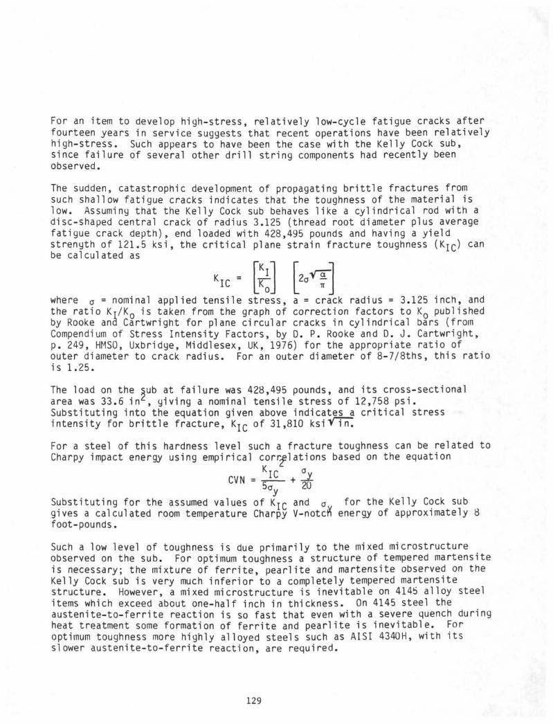
For an item to develop high-stress, relat ively low-cycle fatigue cracks afterfourteen years in service suggests that recent operations have been relat ivelyhigh-stress. Such appears to have been the case with the Kelly Cock sub,since fa i lure of several other d r i l l str ing components had recently beenobserved.
The sudden, catastrophic development of propagating b r i t t l e fractures fromsuch shallow fatigue cracks indicates that the toughness of the material islow. Assuming that the Kelly Cock sub behaves l ike a cyl indrical rod with adisc-shaped central crack of radius 3.125 (thread root diameter plus averagefatigue crack depth), end loaded with 428,495 pounds and having a y ie ldstrength of 121.5 k s i , the c r i t i c a l plane strain fracture toughness (KjC) canbe calculated as
~K.KIC
IK
where andσ = nominal applied tensile stress, a = crack radius = 3.125 inch,the rat io KT/KQ is taken from the graph of correction factors to KQ publishedby Rooke and Cartwright for plane circular cracks in cyl indrical bars (fromCompendium of Stress Intensity Factors, by D. P. Rooke and D. J . Cartwright,p. 249, HMSO, Uxbridge, Middlesex, UK, 1976) for the appropriate rat io ofouter diameter to crack radius. For an outer diameter of 8-7/8ths, th is rat iois 1.25.
The load on the sub at fa i lure was 428,495 pounds, and i t s cross-sectionalarea was 33.6 in , giving a nominal tensile stress of 12,758 p s i .Substituting into the equation given above indicates a c r i t i c a l stressintensity for b r i t t l e fracture, Kj C of 31,810 ksiV i n.
For a steel of th is hardness level such a fracture toughness can be related toCharpy impact energy using empirical correlations based on the equation
CVN = -eh + my
Substituting for the assumed values of Kj C and σ for the Kelly Cock subgives a calculated room temperature Charpy V-notctt energy of approximately 8foot-pounds.Such a low level of toughness is due primarily to the mixed microstructureobserved on the sub. For optimum toughness a structure of tempered martensiteis necessary; the mixture of f e r r i t e , pearl i te and martensite observed on theKelly Cock sub is very much in fer ior to a completely tempered martensitestructure. However, a mixed microstructure is inevitable on 4145 alloy steelitems which exceed about one-half inch in thickness. On 4145 steel theaustenite-to-ferr i te reaction is so fast that even with a severe quench duringheat treatment some formation of f e r r i t e and pearl i te is inevitable. Foroptimum toughness more highly alloyed steels such as AISI 4340H, with i t sslower austenite-to-ferr i te reaction, are required.
129
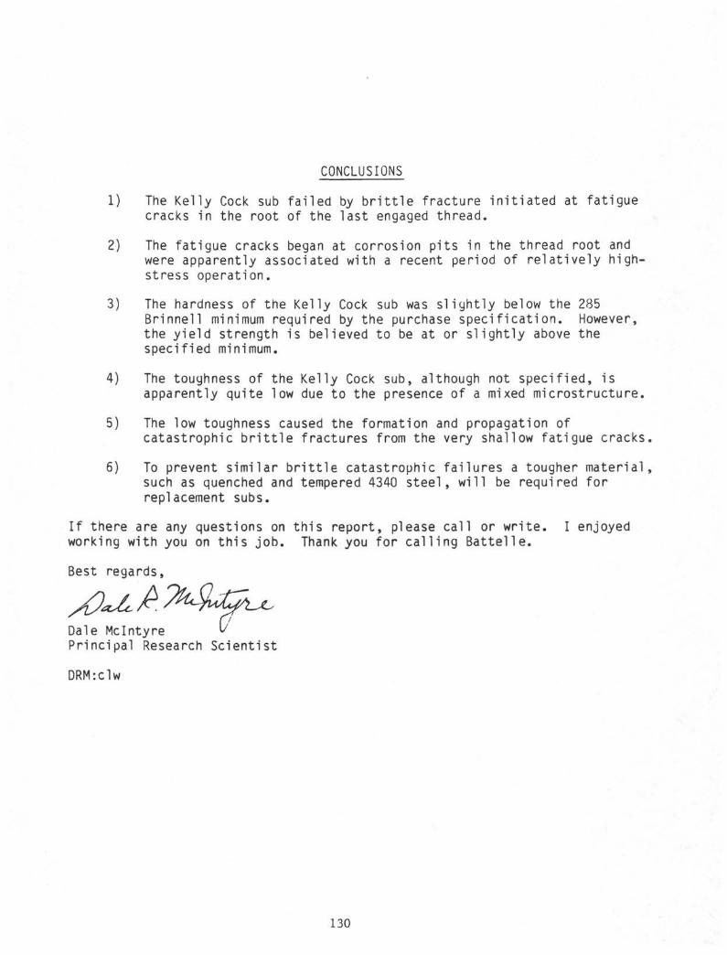
CONCLUSIONS
1) The Kelly Cock sub failed by brittle fracture initiated at fatiguecracks in the root of the last engaged thread.
2) The fatigue cracks began at corrosion pits in the thread root andwere apparently associated with a recent period of relatively high-stress operation.
3) The hardness of the Kelly Cock sub was slightly below the 285Brinnell minimum required by the purchase specification. However,the yield strength is believed to be at or slightly above thespecified minimum.
4) The toughness of the Kelly Cock sub, although not specified, isapparently quite low due to the presence of a mixed microstructure.
5) The low toughness caused the formation and propagation ofcatastrophic brittle fractures from the very shallow fatigue cracks.
6) To prevent similar brittle catastrophic failures a tougher material,such as quenched and tempered 4340 steel, will be required forreplacement subs.
If there are any questions on this report, please call or write. I enjoyedworking with you on this job. Thank you for calling Battelle.
Best regards,
Dale MclntyrePrincipal Research Scientist
DRM:clw
130
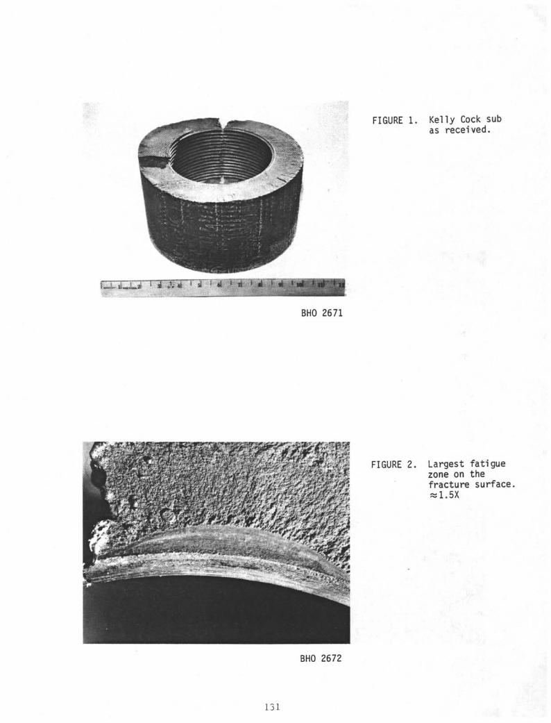
FIGURE 1. Kelly Cock subas received.
BHO 2671
FIGURE 2. Largest fatiguezone on thefracture surface
1.5X
BHO 2672
131
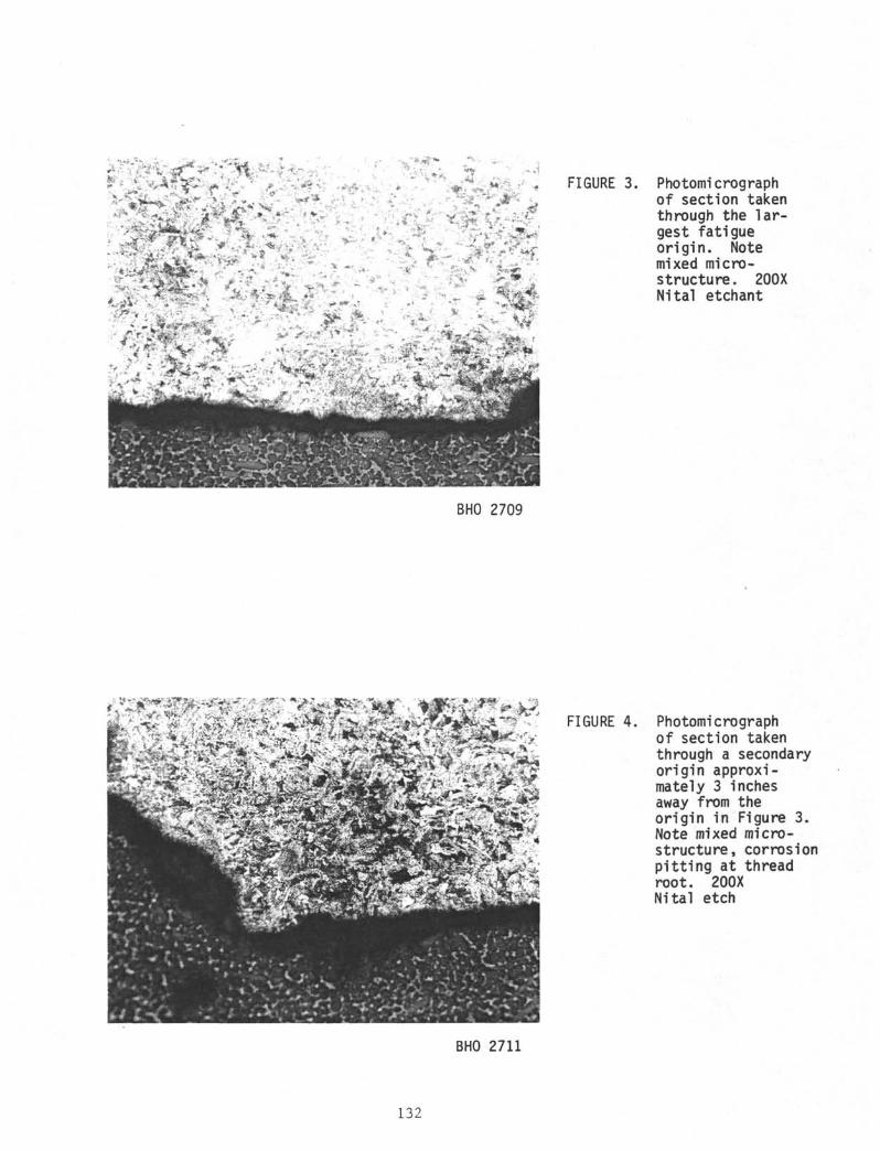
BHO 2709
FIGURE 3. Photomicrographof section takenthrough the lar-gest fatigueorigin. Notemixed micro-structure. 200XNital etchant
FIGURE 4. Photomicrographof section takenthrough a secondaryorigin approxi-mately 3 inchesaway from theorigin in Figure 3.Note mixed micro-structure, corrosionpitting at threadroot. 200XNital etch
BHO 2711
132
APPENDIX C
FAILURE ANALYSIS OF DRILL PIPEFROM HOLE 581A
(LEG 88)
REPORT
on
FAILURE ANALYSIS OF DRILL PIPE FROM HOLE 581A
Contract No. G13274-3O58
to
DEEP SEA DRILLING PROJECT
February 7, 1983
by
D. R. MclntyreR. J. Olson
BATTELLEHouston üperations
2223 West Loop SouthSuite 320
Houston, Texas
Battelle is not engaged in research for advertising, sales promotion,or publicity purposes, and this report may not be reproduced in full or inpart for such purposes.
135
REPORT
on
FAILURE ANALYSIS OF DRILL PIPE FROM HOLE 581ACONTRACT NO.: Gl3274-3058
to
DEEP SEAL DRILLING PROJECT
by
Dale R. MclntyreR.J. Olson
from
BATTELLEHouston Operations
February 7, 1983
SUMMARY
The drill pipe in DSDP hole 581A failed due to buckling followed by fatigue
and final fracture by ductile rupture. The buckling apparently took place
some time before the drill pipe became stuck while retrieving core No. 1 and
was most likely caused by insufficient tension on the drill string. The
mechanical properties and chemical composition of the drill pipe joint met the
requirements of API 5AX in all respects.
INTRODUCTION
On August 25, 1982, The Deep Sea Dr i l l ing Project began work on hole No. 581A,
lowering a re-entry cone and 72.15 m of 16-inch casing to the sea floor in
5483 m of water on a 5 inch, 19.5 pound/ft S-135 d r i l l pipe running string
with a 15-inch core b i t .
136
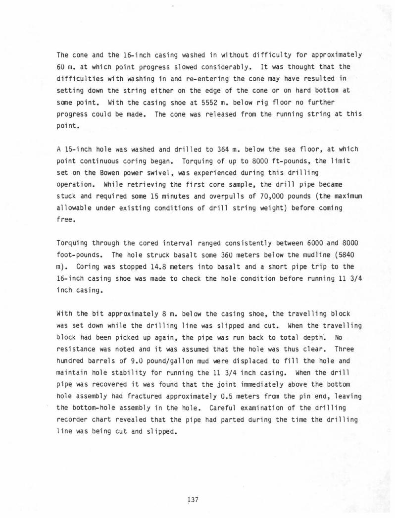
The cone and the 16-inch casing washed in without d i f f i cu l ty for approximately
60 m. at which point progress slowed considerably. I t was thought that the
d i f f i cu l t i es with washing in and re-entering the cone may have resulted in
setting down the string either on the edge of the cone or on hard bottom at
some point. With the casing shoe at 5552 m. below rig floor no further
progress could be made. The cone was released from the running string at this
point.
A 15-inch hole was washed and dr i l led to 364 m. below the sea f loor, at which
point continuous coring began. Torquing of up to 8000 ft-pounds, the l im i t
set on the Bowen power swivel, was experienced during this d r i l l i ng
operation. While retrieving the f i r s t core sample, the d r i l l pipe became
stuck and required some 15 minutes and overpulls of 70,000 pounds (the maximum
allowable under existing conditions of d r i l l string weight) before coming
free.
Torquing through the cored interval ranged consistently between 6000 and 8000
foot-pounds. The hole struck basalt some 360 meters below the mudline (5840
m). Coring was stopped 14.8 meters into basalt and a short pipe t r i p to the
16-inch casing shoe was made to check the hole condition before running 11 3/4
inch casing.
With the bi t approximately 8 m. below the casing shoe, the travell ing block
was set down while the d r i l l i ng l ine was slipped and cut. When the travel l ing
block had been picked up again, the pipe was run back to total depth. No
resistance was noted and i t was assumed that the hole was thus clear. Three
hundred barrels of 9.0 pound/gallon mud were displaced to f i l l the hole and
maintain hole s tabi l i ty for running the 11 3/4 inch casing. When the d r i l l
pipe was recovered i t was found that the jo in t immediately above the bottom
hole assembly had fractured approximately 0.5 meters from the pin end, leaving
the bottom-hole assembly in the hole. Careful examination of the d r i l l i ng
recorder chart revealed that the pipe had parted during the time the d r i l l i ng
l ine was being cut and slipped.
137
Visual Examination
Figure 1 shows the broken sample of drill pipe as received. As Figures 2, 3
and 4 show, the fractured end showed extensive plastic deformation. Around
the circumference of the fracture, material at the twelve and six o-clock
positions had been deformed inward while at the three and nine o1clock
positions the pipe wall had bulged outward. Two longitudinal splits had
occurred on opposite sides of the pipe at the two and eight o1clock positions
(Figures 2 and 3). The split at the two o'clock position ran parallel to the
longitudinal axis of the pipe for approximately six inches before turning
ninety degrees and running perpendicular to the longitudinal axis. (Figure 4)
Virtually all of the fracture surfaces on the broken pipe end were shear
fractures propagating at approximately 45 degrees to the pipe wall
thickness. At the edges of the areas which had bulged outward, two small
half-moon-shaped zones suggestive of fatigue were observed (Figures 5 and 6)
Radial marks in these zones suggested origins on the outer surface of the pipe
(arrows, Figure 7). A secondary crack under the fatigue zone at the three
o1clock position also appeared to be due to fatigue.
Metal!ographic Examination
A section taken through the fatigue zone at the three o'clock position (Figure
7) was polished and etched for metallographic examination. Figure 8 presents
a photomicrograph of the fracture origin. Although damaged by cold-work and
corrosion, the fracture profile appeared to be predominantly transgranular and
non-branching.
Numerous secondary cracks were observed on both the inside and outside surface
of the drill pipe section. Most of these cracks were relatively blunt,
transgranular and filled with corrosion products.
138
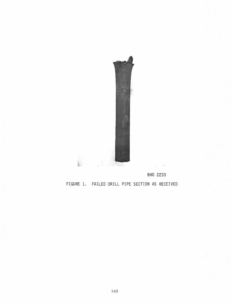
BHO 2233
FIGURE 1. FAILED DRILL PIPE SECTION AS RECEIVED
140
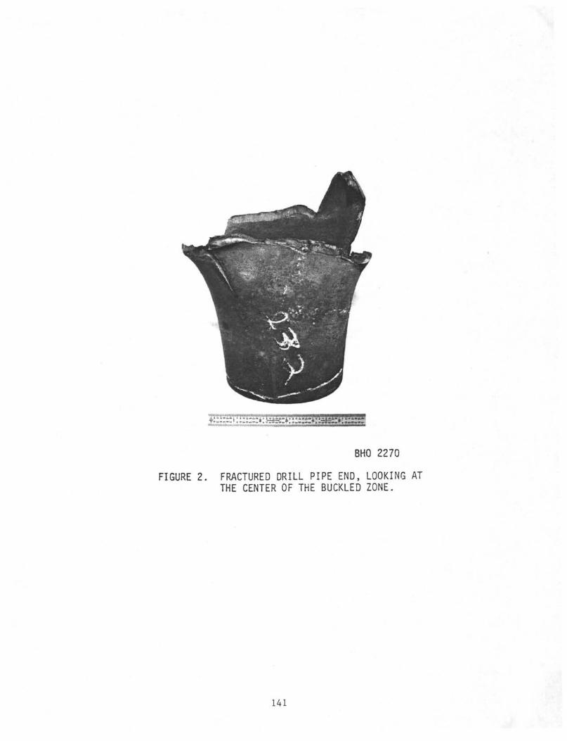
FIGURE 2.
BHO 2270
FRACTURED DRILL PIPE END, LOOKING ATTHE CENTER OF THE BUCKLED ZONE.
141
FIGURE 3. SIDE VIEW OF THE BUCKLELONGIGUDINAL SPLIT.
BHO 2268
NOTE THE
142
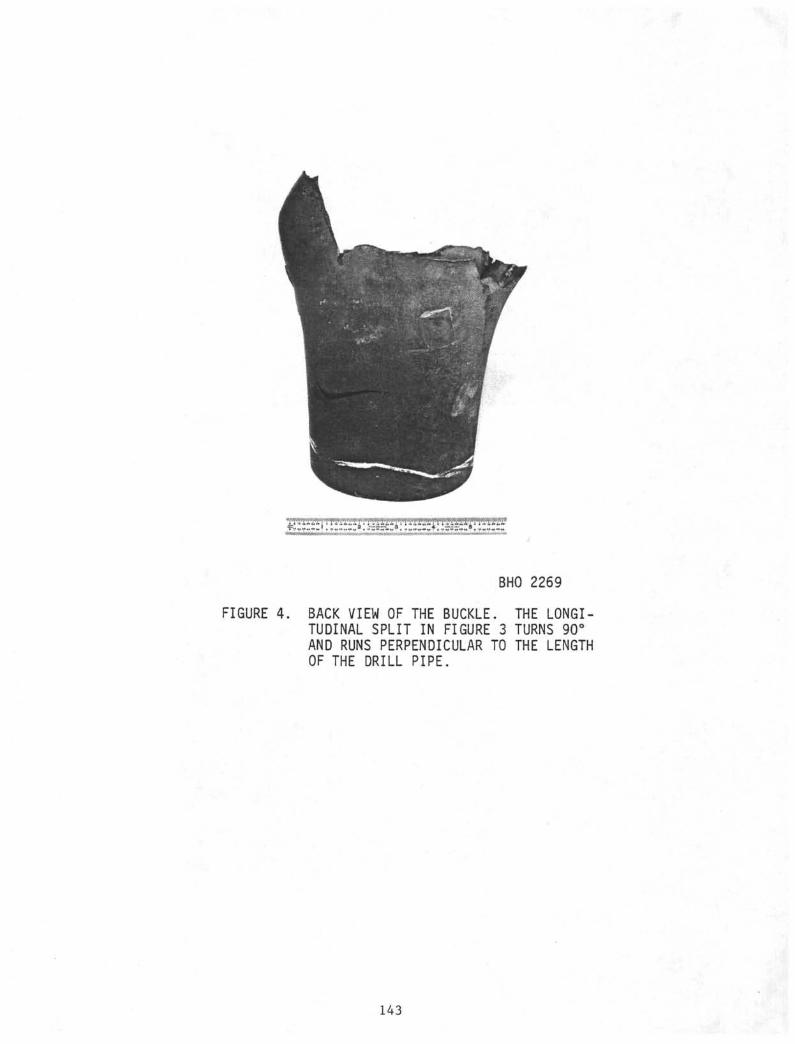
BHO 2269
FIGURE 4. BACK VIEW OF THE BUCKLE. THE LONGI-TUDINAL SPLIT IN FIGURE 3 TURNS 90°AND RUNS PERPENDICULAR TO THE LENGTHOF THE DRILL PIPE.
143
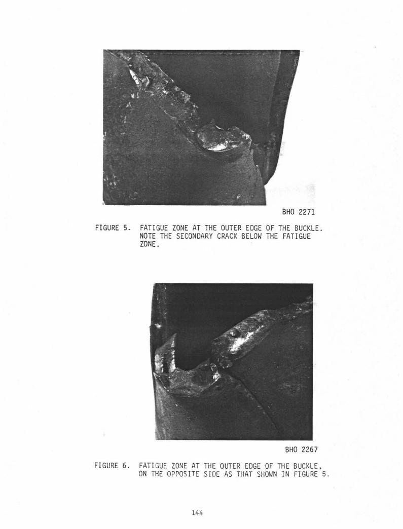
BHO 2271
FIGURE 5. FATIGUE ZONE AT THE OUTER EDGE OF THE BUCKLENOTE THE SECONDARY CRACK BELOW THE FATIGUEZONE.
BHO 2267
FIGURE 6. FATIGUE ZONE AT THE OUTER EDGE OF THE BUCKLE,ON THE OPPOSITE SIDE AS THAT SHOWN IN FIGURE 5
144
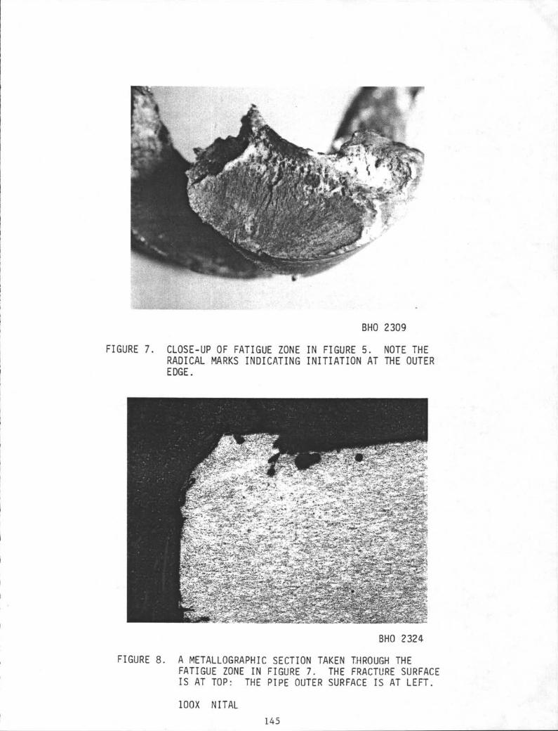
BHO 2309
FIGURE 7. CLOSE-UP OF FATIGUE ZONE IN FIGURE 5. NOTE THERADICAL MARKS INDICATING INITIATION AT THE OUTEREDGE.
FIGURE 8.
,-.,BHO 2324
A METALLOGRAPHIC SECTION TAKEN THROUGH THEFATIGUE ZONE IN FIGURE 7. THE FRACTURE SURFACEIS AT TOP: THE PIPE OUTER SURFACE IS AT LEFT.
100X NITAL145
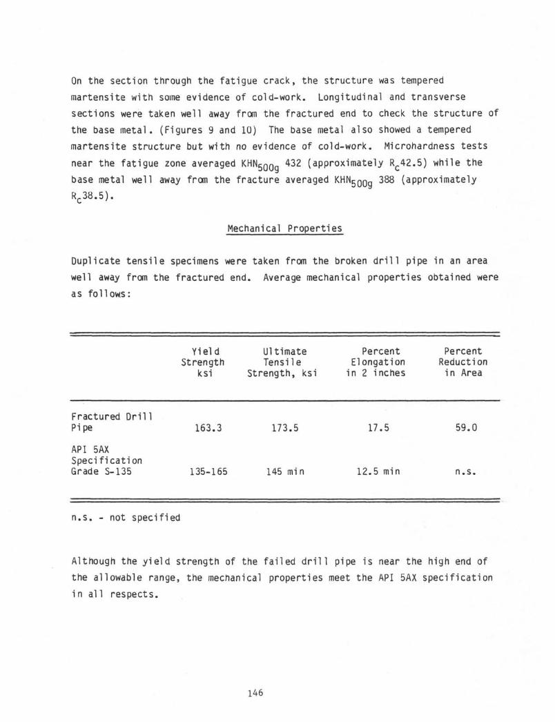
On the section through the fatigue crack, the structure was tempered
martensite with some evidence of cold-work. Longitudinal and transverse
sections were taken well away from the fractured end to check the structure of
the base metal. (Figures 9 and 10) The base metal also showed a tempered
martensite structure but with no evidence of cold-work. Microhardness tests
near the fatigue zone averaged KHN 5 0 0 432 (approximately RC42.5) while the
base metal well away from the fracture averaged KHN^QQQ 388 (approximately
RC38.5).
Mechanical Properties
Duplicate tensile specimens were taken from the broken drill pipe in an area
well away from the fractured end. Average mechanical properties obtained were
as follows:
Fractured Dril1Pipe
API 5AXSpecificationGrade S-135
YieldStrength
ksi
163.3
135-165
UltimateTensile
Strength, ksi
173.5
145 min
PercentElongation
in 2 inches
17.5
12.5 min
PercentReduction
in Area
59.0
n.s.
n.s. - not specified
Although the yield strength of the failed drill pipe is near the high end of
the allowable range, the mechanical properties meet the API 5AX specification
in al 1 respects.
146
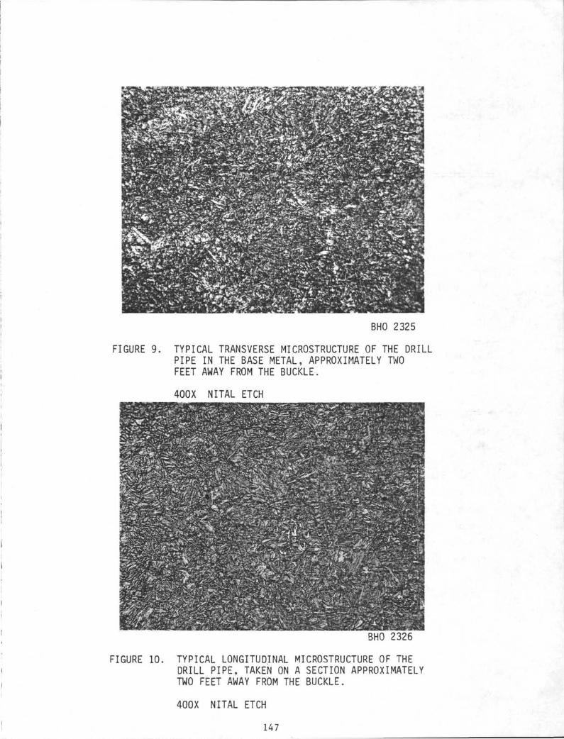
BHO 2325
FIGURE 9. TYPICAL TRANSVERSE MICROSTRUCTURE OF THE DRILLPIPE IN THE BASE METAL, APPROXIMATELY TWOFEET AWAY FROM THE BUCKLE.
400X NITAL ETCH
mwm• . •>
%m
In
1
É0wMPWH
ii1WPP"s i ^ ^ ^ ^ ‰
1iiiI
• . : • O • • '
-
WxSmQaBbPwBSàBHO 2326
FIGURE 10. TYPICAL LONGITUDINAL MICROSTRUCTURE OF THEDRILL PIPE, TAKEN ON A SECTION APPROXIMATELYTWO FEET AWAY FROM THE BUCKLE.
400X NITAL ETCH
147
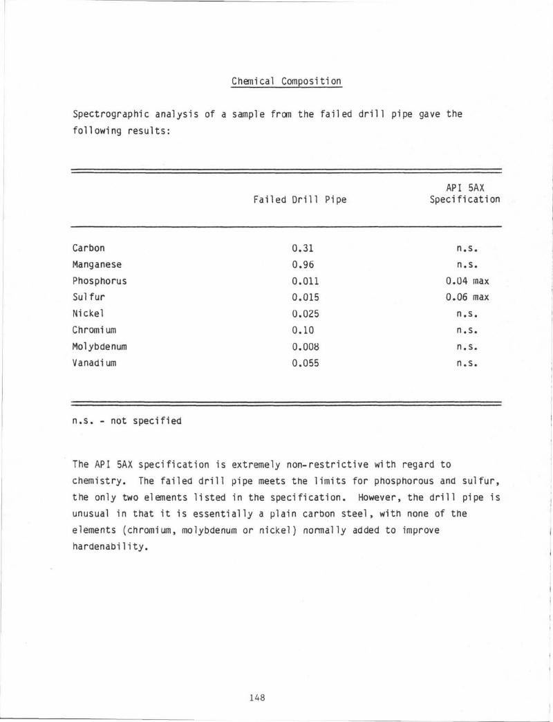
Chemical Composition
Spectrographc analysis of a sample from the fai led d r i l l pipe gave the
following results:
API 5AXFailed Dr i l l Pipe Specification
Carbon 0.31 n.s.
Manganese 0.96 n.s.
Phosphorus 0.011 0.04 max
Sulfur 0.015 0.06 max
Nickel 0.025 n.s.
Chromium 0.10 n.s.
Molybdenum 0.008 n.s.
Vanadium 0.055 n.s.
n.s. - not specified
The API 5AX specification is extremely non-restrictive with regard to
chemistry. The fai led d r i l l pipe meets the l imi ts for phosphorous and sulfur,
the only two elements l is ted in the specif icat ion. However, the d r i l l pipe is
unusual in that i t is essentially a plain carbon steel , with none of the
elements (chromium, molybdenum or nickel) normally added to improve
hardenability.
148
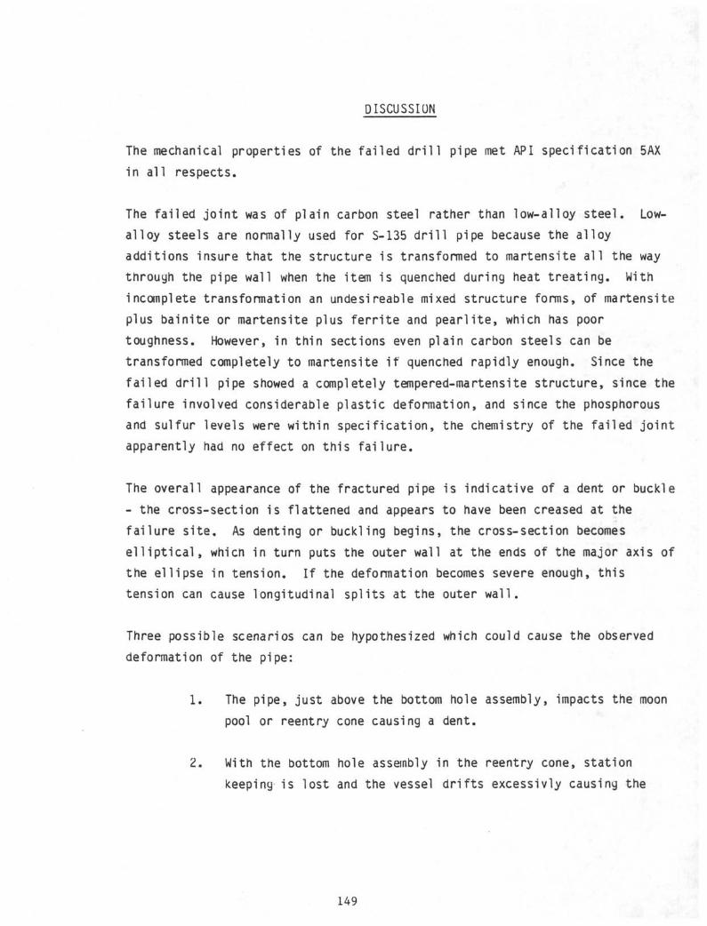
DISCUSSION
The mechanical properties of the fai led d r i l l pipe met API specification 5AX
in al l respects.
The fai led jo in t was of plain carbon steel rather than low-alloy steel. Low-
alloy steels are normally used for S-135 d r i l l pipe because the alloy
additions insure that the structure is transformed to martensite a l l the way
through the pipe wall when the item is quenched during heat t reat ing. With
incomplete transformation an undesireable mixed structure forms, of martensite
plus bainite or martensite plus fe r r i te and pear l i te, which has poor
toughness. However, in thin sections even plain carbon steels can be
transformed completely to martensite i f quenched rapidly enough. Since the
fai led d r i l l pipe showed a completely tempered-martensite structure, since the
fai lure involved considerable plastic deformation, and since the phosphorous
and sulfur levels were within specif ication, the chemistry of the fai led jo in t
apparently had no effect on this fa i lu re .
The overall appearance of the fractured pipe is indicative of a dent or buckle
- the cross-section is flattened and appears to have been creased at the
fai lure s i te . As denting or buckling begins, the cross-section becomes
e l l i p t i c a l , which in turn puts the outer wall at the ends of the major axis of
the el l ipse in tension. I f the deformation becomes severe enough, this
tension can cause longitudinal spl i ts at the outer wal l .
Three possible scenarios can be hypothesized which could cause the observed
deformation of the pipe:
1. The pipe, just above the bottom hole assembly, impacts the moon
pool or reentry cone causing a dent.
Z. With the bottom hole assembly in the reentry cone, station
keeping is lost and the vessel d r i f t s excessivly causing the
149
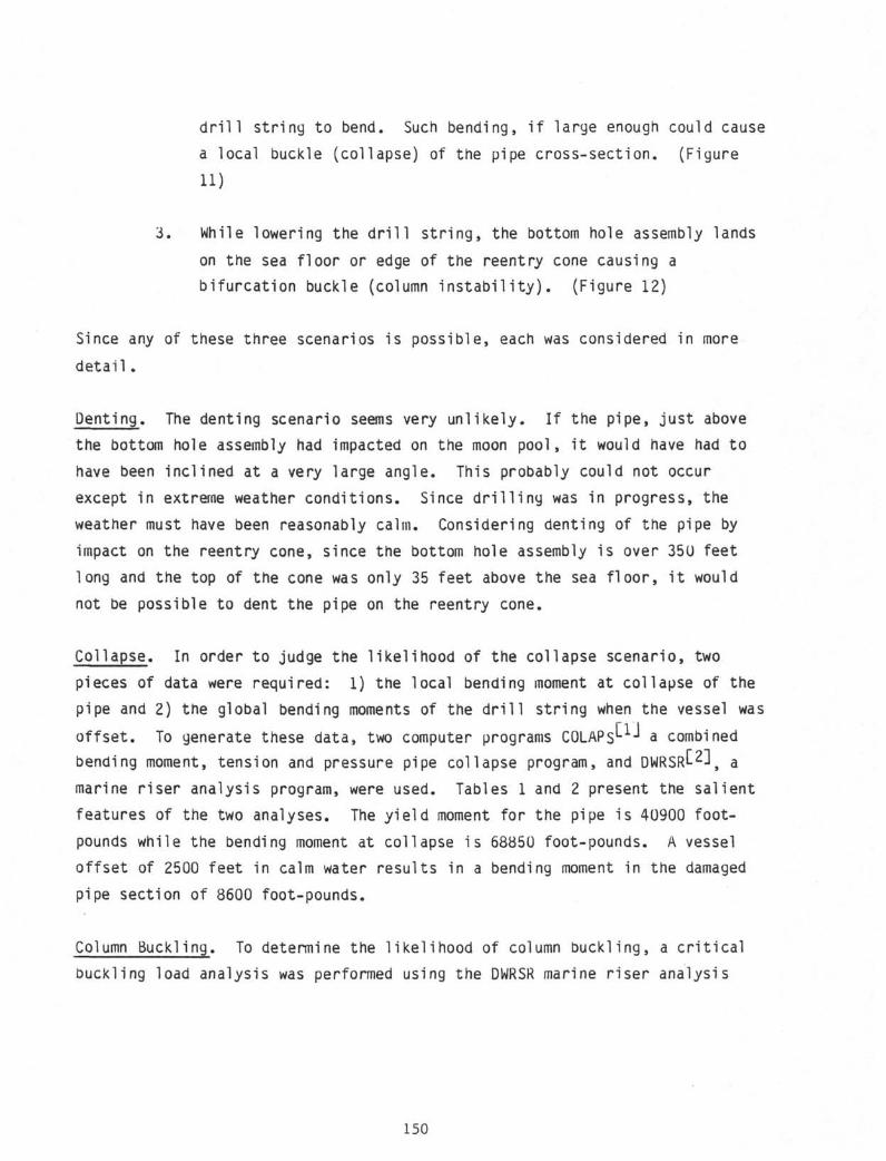
drill string to bend. Such bending, if large enough could cause
a local buckle (collapse) of the pipe cross-section. (Figure
11)
3. While lowering the drill string, the bottom hole assembly lands
on the sea floor or edge of the reentry cone causing a
bifurcation buckle (column instability). (Figure 12)
Since any of these three scenarios is possible, each was considered in more
detail.
Denting. The denting scenario seems very unlikely. If the pipe, just above
the bottom hole assembly had impacted on the moon pool, it would have had to
have been inclined at a very large angle. This probably could not occur
except in extreme weather conditions. Since drilling was in progress, the
weather must have been reasonably calm. Considering denting of the pipe by
impact on the reentry cone, since the bottom hole assembly is over 35U feet
long and the top of the cone was only 35 feet above the sea floor, it would
not be possible to dent the pipe on the reentry cone.
Collapse. In order to judge the likelihood of the collapse scenario, two
pieces of data were required: 1) the local bending moment at collapse of the
pipe and 2) the global bending moments of the drill string when the vessel was
offset. To generate these data, two computer programs COLAPs'- -" a combined
bending moment, tension and pressure pipe collapse program, and DWRSR"-^ amarine riser analysis program, were used. Tables 1 and 2 present the salient
features of the two analyses. The yield moment for the pipe is 40900 foot-
pounds while the bending moment at collapse is 68850 foot-pounds. A vessel
offset of 2500 feet in calm water results in a bending moment in the damaged
pipe section of 8600 foot-pounds.
Column Buckling. To determine the likelihood of column buckling, a critical
buckling load analysis was performed using the DWRSR marine riser analysis
150
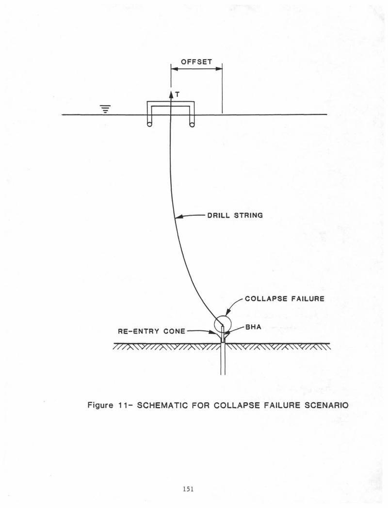
OFFSET
DRILL STRING
RE-ENTRY CONE
COLLAPSE FAILURE
Figure 1 1 - SCHEMATIC FOR COLLAPSE FAILURE SCENARIO
151
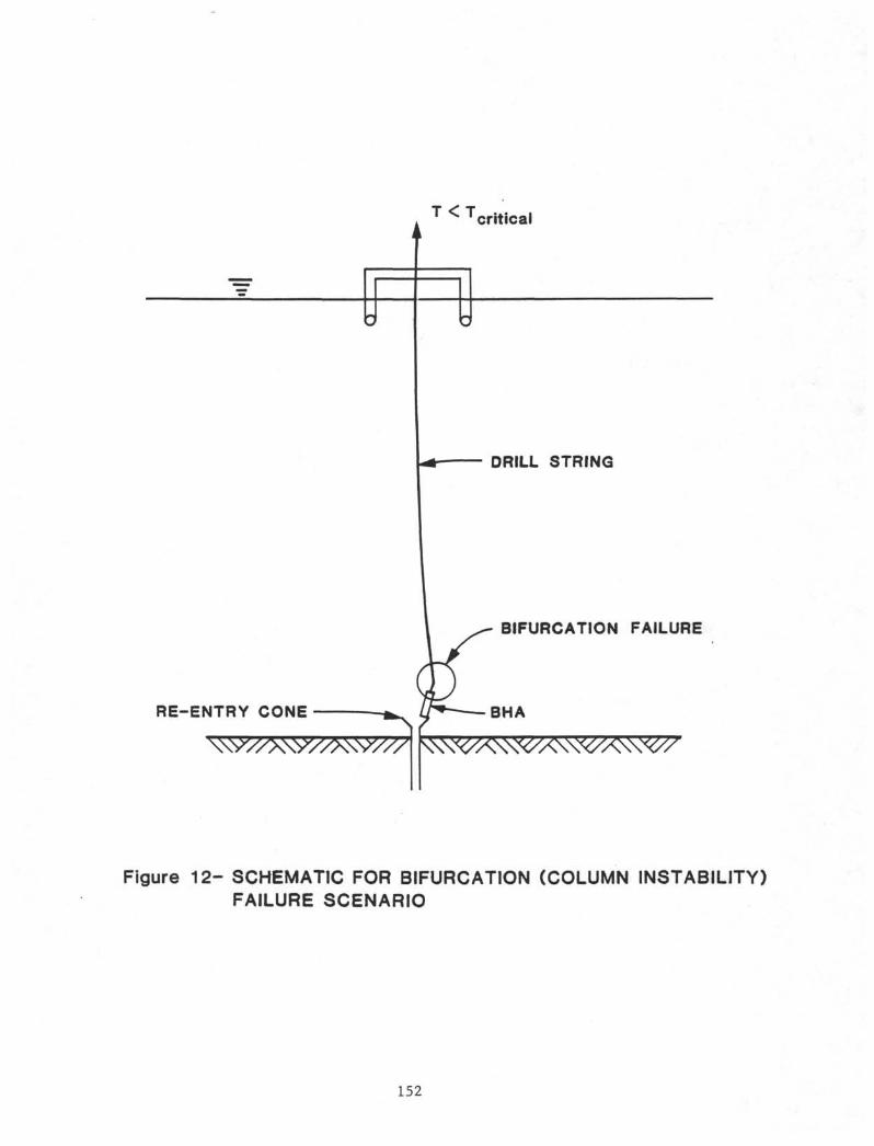
c
T <
-
Tcritical
w
- DRILL STRING
BIFURCATION FAILURE
RE-ENTRY CONE
Figure 12- SCHEMATIC FOR BIFURCATION (COLUMN INSTABILITY)FAILURE SCENARIO
152
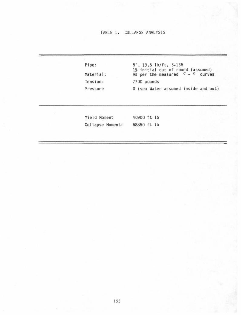
TABLE 1. COLLAPSE ANALYSIS
Pipe:
Mater ia l :
Tension:
Pressure
5", 19.5 I b / f t , S-1351% i n i t i a l out of round (assumed)As per the measured σ - ε curves
7700 pounds
0 (sea Water assumed inside and out)
Yield Moment
Collapse Moment
40900 ft lb
68850 ft lb
153
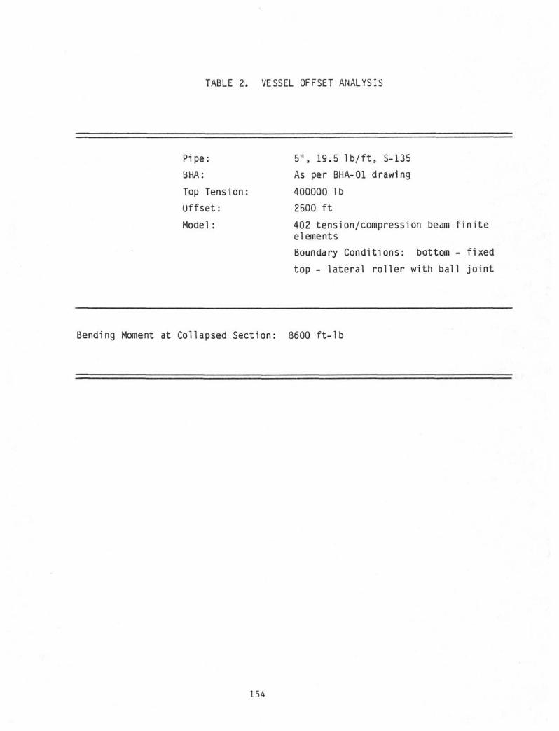
TABLE 2. VESSEL OFFSET ANALYSIS
Pipe: 5" , 19.5 l b / f t , S-135
BHA: As per BHA-01 drawing
Top Tension: 400000 lb
Offset : 2500 f t
Model: 402 tension/compression beam f i n i t eelements
Boundary Condit ions: bottom - f ixed
top - lateral rol ler with ball jo in t
Bending Moment at Collapsed Section: 8600 f t - l b
154
program. The relevant data for this analysis is shown in Table 3. The
buckling load, 325,000 pounds is the minimum tension that must be applied to
the top of the drill string to prevent buckling.
Considering all three possible causes for the initial damage to the drill
pipe, column instability seems to be the most likely cause of the failure.
Denting has been ruled out as physically unlikely. Collapse, while physically
possible, is deemed unlikely because of the fact that to even approach the
yield moment would require an offset in excess of 2500 feet. Column buckling
on the other hand, seems quite reasonable - the buckling tension is very near
the operating tension (400000 pounds) and the buckling mode shape results in
the occurrence of the maximum moment in the drill stem at the pipe joint just
above the bottom hole assembly. It should be noted that in the analyses
performed, conditions have been idealized in that no waves, no current were
considered and a shell approximation for collapse analysis was used. Such sea
state and vessel offset data are unavailable for a more detailed analysis.
The inclusion of such effects as the dynamic tension variation due to vessel
heave and the influence of initial curvature due to waves and current would
likely aggravate the buckling problem. In view of these analyses, the
evidence strongly favors loss of tension due to drill string loads on the re-
entry cone as the initial cause of the ovalization or buckling damage to the
pipe.
After it buckled, the drill pipe did not part immediately. The fatigue zones
on the outer edges of the buckled area suggest that after buckling, the drill
pipe continued to operate for perhaps several thousand cycles. During this
time at least three fatigue cracks initiated and began to grow on the outer
edges of the buckled zone. The heavy overpulls necessary to free the stuck
drill pipe probably caused some of the remaining ligament to part. Final
fracture occurred by ductile rupture in tension when the string was lifted to
be slipped and cut.
155
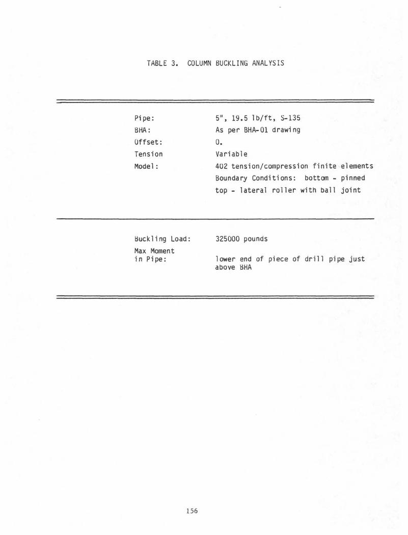
TABLE 3. COLUMN BUCKLING ANALYSIS
Pipe:
BHA:
Offset:
Tension
Model :
5", 19.5 l b / f t , S-135As per BHA-01 drawing
0.
Variable
402 tension/compression finite elements
Boundary Conditions: bottom - pinned
top - lateral roller with ball joint
Buckling Load
Max Momentin Pipe:
325000 pounds
lower end of piece of drill pipe justabove BHA
156
This evidence suggests that the buckle which initiated this failure occurred
some time before the drill pipe became stuck while retrieving core No. 1.
CONCLUSIONS
1. The failure of the drill pipe in DSDP hole 581A was initiated by a
buckling of the drill pipe.
2. Buckling apparently took place some time before the drill pipe became
stuck while attempting to retrieve core No. 1. It is likely that it
occurred during the setting of the 16 inch casing.
3. The buckle which initiated this failure was probably caused by
insufficient tension in the drill string resulting from setting of the
pipe on the sea floor or edge of the reentry cone.
4. After buckling the drill pipe did not part immediately. Several thousand
cycles of rotation occurred while fatigue cracks formed at the cold-
worked outer edges of the buckled zone. Final fracture occurred by
ductile rupture in tension.
5. The mechanical properties of the failed drill pipe joint met the API
specification 5AX in all respects.
6. The chemical composition of the drill pipe met the API 5AX specification
limits for phosphorous and sulfur, the only elements required. Although
the failed drill pipe joint was of plain carbon steel rather than low-
alloy steel, the chemical composition apparently had no effect on this
failure.
157
REFERENCES
1 . K i n g e l , e t a l . ; Summary Report on the I n e l a s t i c Col lapse and Buckl ing ofDeep Water P ipe l i nes Under Combined Movement, Pressure, and Ax ia lTension; Report t o B a t t e l l e ' s Deep Water Of fshore P i p e l i n e Group; March,1976.
2 . Olson, e t a l . ; App l i ca t i ons Manual f o r DWRSR Riser Ana lys is Program;Report t o B a t t e l l e ' s Deep Water Marine Riser Group; June, 1982.
158
APPENDIX D
OPERATIONS DURING SEVERE WEATHER
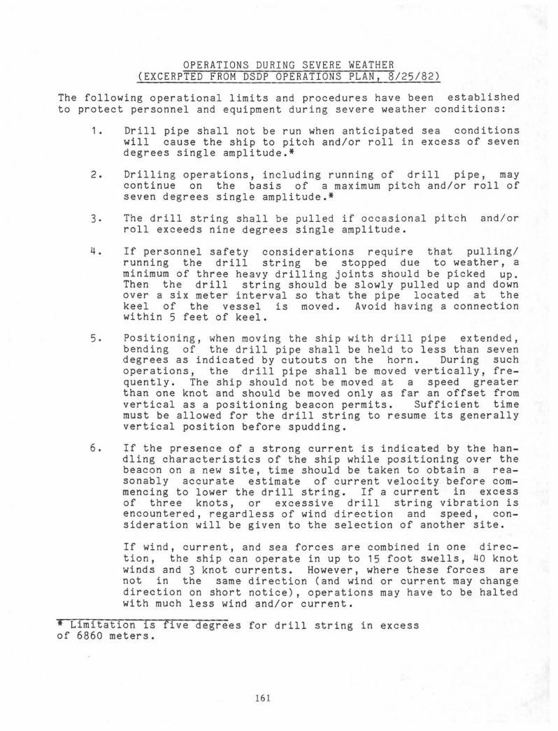
OPERATIONS DURING SEVERE WEATHER(EXCERPTED FROM DSDP OPERATIONS PLAN, 8/25/82)
The following operational limits and procedures have been establishedto protect personnel and equipment during severe weather conditions:
1. Drill pipe shall not be run when anticipated sea conditionswill cause the ship to pitch and/or roll in excess of sevendegrees single amplitude.*
2. Drilling operations, including running of drill pipe, maycontinue on the basis of a maximum pitch and/or roll ofseven degrees single amplitude.*
3. The drill string shall be pulled if occasional pitch and/orroll exceeds nine degrees single amplitude.
4. If personnel safety considerations require that pulling/running the drill string be stopped due to weather, aminimum of three heavy drilling joints should be picked up.Then the drill string should be slowly pulled up and downover a six meter interval so that the pipe located at thekeel of the vessel is moved. Avoid having a connectionwithin 5 feet of keel.
5. Positioning, when moving the ship with drill pipe extended,bending of the drill pipe shall be held to less than sevendegrees as indicated by cutouts on the horn. During suchoperations, the drill pipe shall be moved vertically, fre-quently. The ship should not be moved at a speed greaterthan one knot and should be moved only as far an offset fromvertical as a positioning beacon permits. Sufficient timemust be allowed for the drill string to resume its generallyvertical position before spudding.
6. If the presence of a strong current is indicated by the han-dling characteristics of the ship while positioning over thebeacon on a new site, time should be taken to obtain a rea-sonably accurate estimate of current velocity before com-mencing to lower the drill string. If a current in excessof three knots, or excessive drill string vibration isencountered, regardless of wind direction and speed, con-sideration will be given to the selection of another site.
If wind, current, and sea forces are combined in one direc-tion, the ship can operate in up to 15 foot swells, MO knotwinds and 3 knot currents. However, where these forces arenot in the same direction (and wind or current may changedirection on short notice), operations may have to be haltedwith much less wind and/or current.
* Limitation is five <Tegrees for drill string in excessof 6860 meters.
161
APPENDIX E
MECHANICAL AND METALLURGICAL EVALUATIONOF S-135 DRILL PIPE
REPORT
on
MECHANICAL AND METALLURGICALEVALUATION OF S-135 DRILL PIPE
Contract No. 613068-3058
to
DEEP SEA DRILLING PROJECT
August 30, 1982
by
D. R. Mclntyre
BATTELLEHouston Operations2223 West Loop South
Houston, Texas
Battelle is not engaged in research for advertising, sales promotion,or publicity purposes, and this report may not be reproduced in full or in partfor such purposes.
165
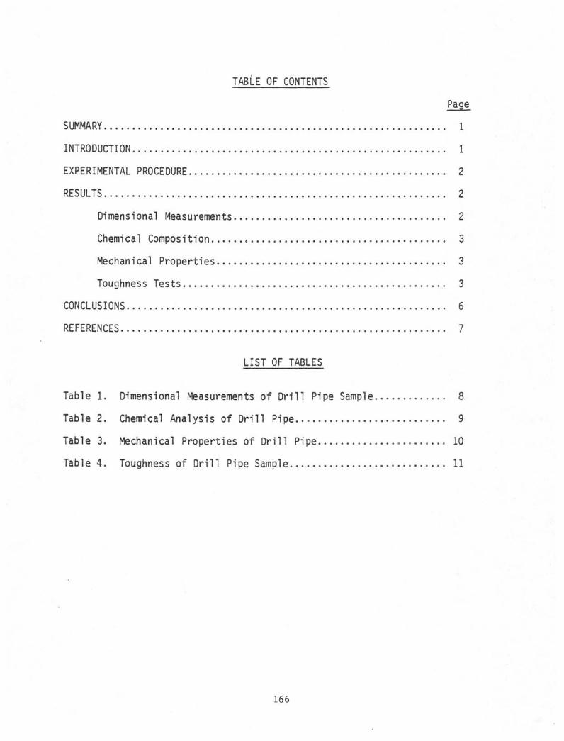
TABLE OF CONTENTS
Page
SUMMARY 1
INTRODUCTION 1
EXPERIMENTAL PROCEDURE ........... 2
RESULTS 2
Dimensional Measurements 2
Chemical Composition * 3
Mechanical Properties 3
Toughness Tests 3
CONCLUSIONS 6
REFERENCES 7
LIST OF TABLES
Table 1. Dimensional Measurements of Drill Pipe Sample............. 8
Table 2. Chemical Analysis of Drill Pipe..... 9
Table 3. Mechanical Properties of Drill Pipe 10
Table 4. Toughness of Drill Pipe Sample 11
166
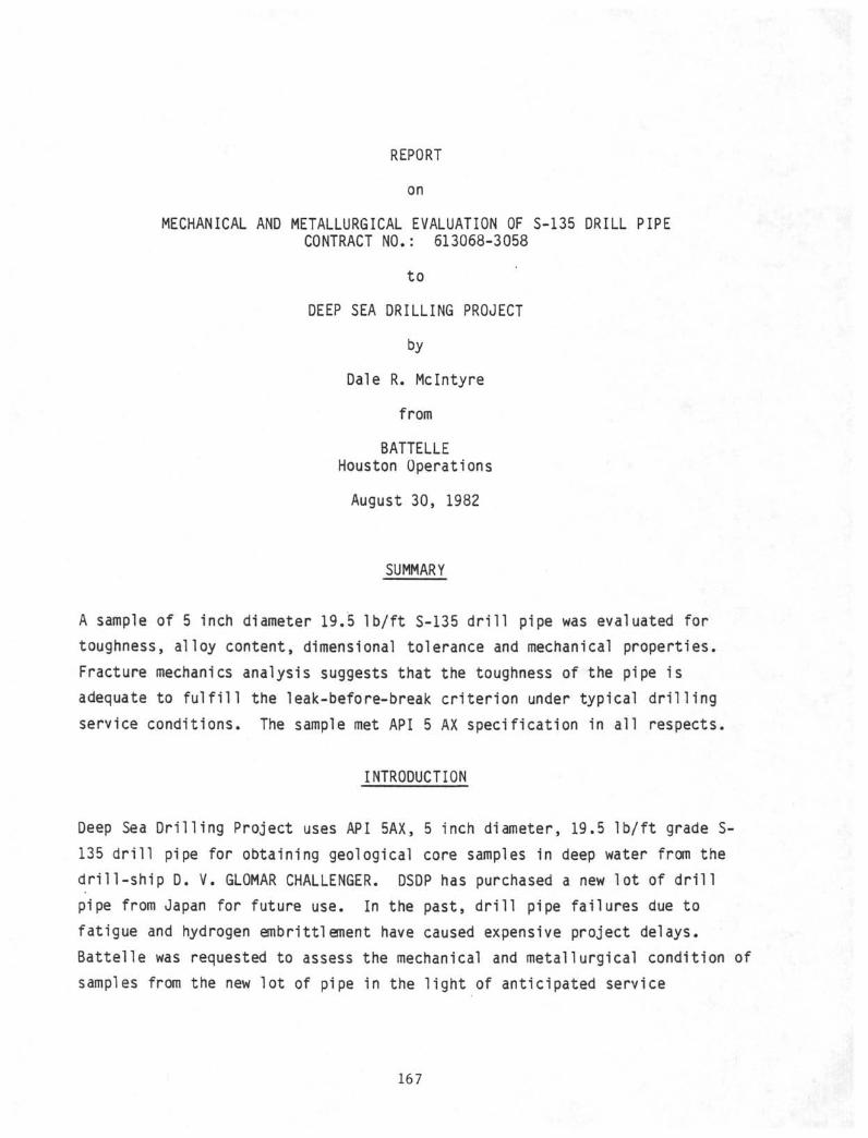
REPORT
on
MECHANICAL AND METALLURGICAL EVALUATION OF S-135 DRILL PIPECONTRACT NO.: 613068-3058
to
DEEP SEA DRILLING PROJECT
by
Dale R. Mclntyre
from
BATTELLEHouston Operations
August 30, 1982
SUMMARY
A sample of 5 inch diameter 19.5 l b / f t S-135 d r i l l pipe was evaluated for
toughness, alloy content, dimensional tolerance and mechanical properties.
Fracture mechanics analysis suggests that the toughness of the pipe is
adequate to f u l f i l l the leak-before-break cr i ter ion under typical d r i l l i ng
service conditions. The sample met API 5 AX specification in al l respects
INTRODUCTION
Deep Sea Drilling Project uses API 5AX, 5 inch diameter, 19.5 lb/ft grade S-
135 drill pipe for obtaining geological core samples in deep water from the
drill-ship D. V. GLOMAR CHALLENGER. DSDP has purchased a new lot of drill
pipe from Japan for future use. In the past, drill pipe failures due to
fatigue and hydrogen embrittlement have caused expensive project delays.
Battelle was requested to assess the mechanical and metallurgical condition of
samples from the new lot of pipe in the light of anticipated service
167
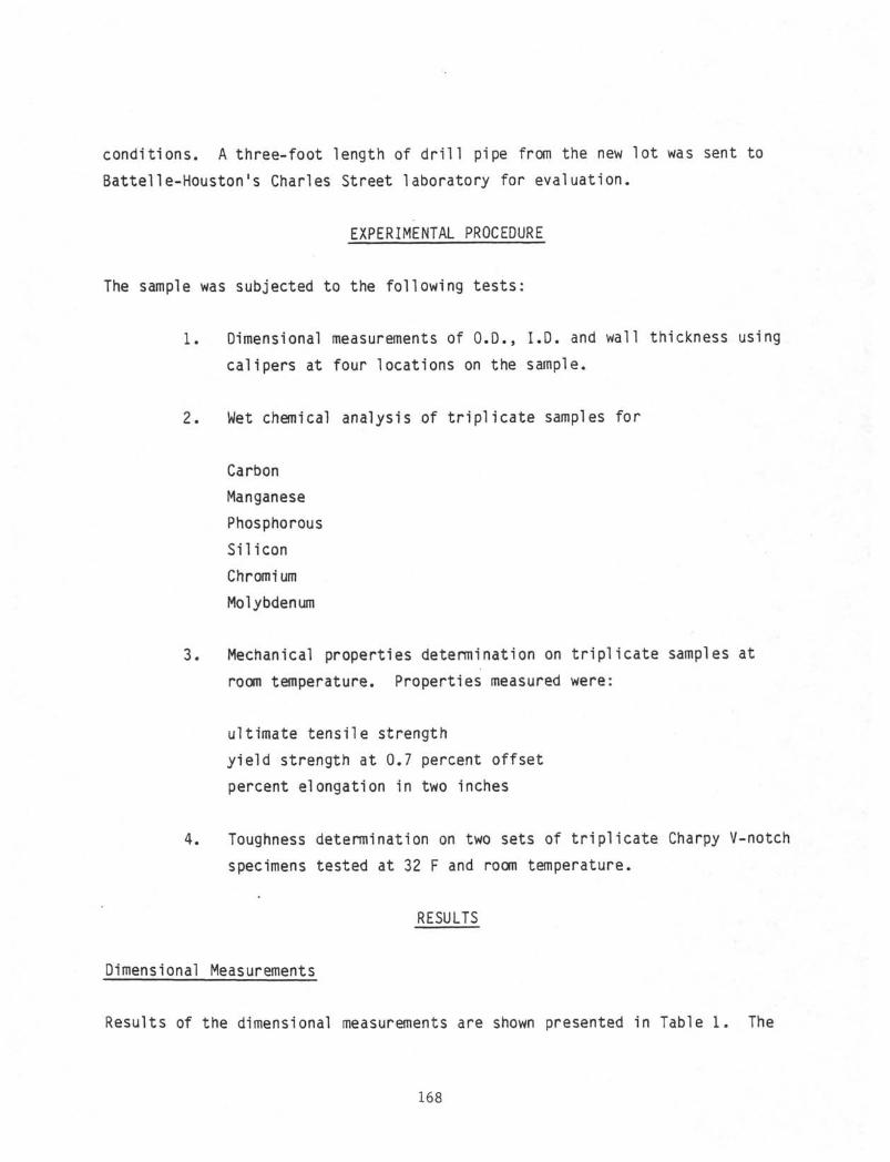
cond i t i ons . A th ree - foo t length of d r i l l pipe from the new l o t was sent to
Bat te l le-Houston 's Charles Street laboratory for eva lua t ion .
EXPERIMENTAL PROCEDURE
The sample was subjected to the fo l lowing t e s t s :
1 . Dimensional measurements of O.D., I .D. and wall thickness using
ca l ipers at four locat ions on the sample.
2 . Wet chemical analysis of t r i p l i c a t e samples fo r
Carbon
Manganese
Phosphorous
Silicon
Chromi urn
Molybdenum
3. Mechanical properties determination on triplicate samples at
room temperature. Properties measured were:
ultimate tensile strength
yield strength at 0.7 percent offset
percent elongation in two inches
4. Toughness determination on two sets of triplicate Charpy V-notch
specimens tested at 32 F and room temperature.
RESULTS
Dimensional Measurements
Results of the dimensional measurements are shown presented in Table 1. The
168
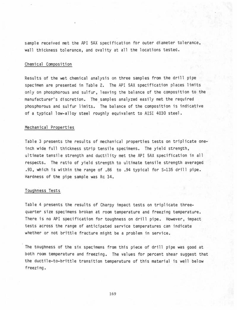
sample received met the API 5AX specification for outer diameter tolerance,
wall thickness tolerance, and ovality at all the locations tested.
Chemical Composition
Results of the wet chemical analysis on three samples from the drill pipe
specimen are presented in Table 2. The API 5AX specification places limits
only on phosphorous and sulfur, leaving the balance of the composition to the
manufacturer1s discretion. The samples analyzed easily met the required
phosphorous and sulfur limits. The balance of the composition is indicative
of a typical low-alloy steel roughly equivalent to AISI 4030 steel.
Mechanical Properties
Table 3 presents the results of mechanical properties tests on triplicate one-
inch wide full thickness strip tensile specimens. The yield strength,
ultimate tensile strength and ductility met the API 5AX specification in all
respects. The ratio of yield strength to ultimate tensile strength averaged
.93, which is within the range of .86 to .94 typical for S-135 drill pipe.
Hardness of the pipe sample was Re 34.
Toughness Tests
Table 4 presents the results of Charpy impact tests on triplicate three-
quarter size specimens broken at room temperature and freezing temperature.
There is no API specification for toughness on drill pipe. However, impact
tests across the range of anticipated service temperatures can indicate
whether or not brittle fracture might be a problem in service.
The toughness of the six specimens from this piece of drill pipe was good at
both room temperature and freezing. The values for percent shear suggest that
the ductile-to-brittle transition temperature of this material is well below
freezing.
169
The specimens used were three-quarter size since the pipe wall thickness was
too thin to permit the use of the standard ten millimeter wide Charpy
specimen. The ASTM standards which allow the use of both ten-millimeter and
three-quarter size Charpy specimens typical ly use a ratio of 0.80 for
comparing the absorbed energy values of low-alloy steels. Thus 20 foot-pounds
of absorbed energy in a standard ten-millimeter Charpy corresponds to 16 foot-
pounds of energy in a three quarter size Charpy. l j 2 This correlation is
perforce approximate and may not be valid for al l materials at al l yield
strengths. However, using this r a t i o , the observed average absorbed energy
values would correspond to ful l-s ize impact values of 49. 6 foot-pounds at
room temperature and 37 foot-pounds at freezing temperature.
For d r i l l pipe, there are no toughness c r i t e r i a specified in API 5AX
specification. However, the level of toughness required for satisfactory
service can be estimated as follows:
The most desirable service requirement for d r i l l pipe is that any fatigue
cracks which form should leak before they break, allowing detection before the
string parts. The leak-before-break cr i ter ion means that the pipe must be
able to sustain a circumferential through-thickness crack without catastrophic
b r i t t l e fa i lure. The stress intensity generated by a circumferential through-
thickness crack twice as long as the wall thickness can be approximated with
the relationship:
K = σ V T
Where σ
= the applied stress, T = the wall thickness, and K = the stress
intensity. At the specified minimum yield strength of S-135, a 2T through-
thickness circumferential crack would generate
135000 ( πx 0.362)
1 / 2 = 143,000 ksi VTn"
of stress intensity.
170
The cr i t ica l stress intensity a material can sustain without b r i t t l e fracture,
Kjç, can be estimated from the Charpy impact values using Barsom, Rolfe and
Novak's empirical correlations between Krç and Charpy test results on the
upper shelf and in the transition region between b r i t t l e and ductile
behaviour.
At room temperature, the calculated fu l l -s ize Charpy impact value averaged
49.6 foot-pounds. Fracture was 100 percent duct i le, so the upper shelf
equation from Barsom, Rolf and Novak applies.
K C
For n = 152 ks i , Cv = 49.6 f t - l bs , the calculated KlC - 179 ksi i n .
Therefore, the d r i l l pipe sample could sustain a 2T through-thickness
circumferential crack at any stress up to and beyond the yield strength with
no danger of b r i t t l e fracture.
At freezing temperature, the calculated fu l l -s ize Charpy impact values average
37 foot-pounds. Some cleavage fracture was present on the specimens, so the
material is in the transit ion region and the following correlation between KJQ
and CVN can be used:
If Cy - 37 f t - lbs and E = 29,000,000 psi , KIC = 114 ksi >JTrü
Therefore at freezing temperature this material could sustain a 2T through-
thickness circumferential crack up to stresses of:
σ= 114,000/(TTX 0.362)1 / 2 = 107,000 psi .
In 5 inch O.D. 19.5 I b / f t d r i l l pipe this would be equivalent to a total
string weight of 583,000 pounds. I f through-thickness fatigue cracks are
present at freezing temperatures with total load in excess of 583,000 pounds,
then b r i t t l e fracture is possible.
171
These calculations are approximate and based on two empirical correlations
rather than direct measurement of the drill pipe toughness. However, they
indicate that this materials toughness is entirely adequate at ambient
temperatures under any elastic loading condition. At 0°C the material's
toughness is adequate up to 80 percent of the specified minimum yield
strength. At stresses above this level fatigue cracks might not leak before
the string parts.
CONCLUSIONS
1. The drill pipe sample submitted met the API 5AX dimensional requirements
in all respects.
2. The sample submitted met the chemical composition requirements of API 5AX
and is typical of low-alloy steels in widespread use for this service.
3. The sample submitted met the API 5AX mechanical properties requirements in
all respects.
4. The room temperature toughness of the sample submitted was sufficient to
ensure leakage of any crack before brittle fracture at any load up to the
specified minimum yield strength.
5. The toughness of the sample submitted was still good at 0°C, although
cracks might not leak before breaking if the pipe is stressed in excess of
80 percent of the specified minimum yield strength.
172
REFERENCES
1 . ASTM A320-80B, "Al loy Steel Bol t ing Material fo r Low-Temperature Service"
American Society for Testing and Mater ia ls , 1981 Annual Book of ASTM
Standards, Part 1 , p.231-240.
2. ASTM A333-79, "Seamless and Welded Steel Pipe for Low-Temperature Service"
American Society for Testing and Mater ia ls , 1981 Annual Book of ASTM
Standards, Part 1 , p. 241-249.
3. "St ress- In tens i ty Factor for a Circumferential Through-wall Crack in a
Stra ight Pipe," Gilman, J . D. Report GEAP-5557 General E lec t r i c Co. APED,
San Jose, Ca l i f , 1968.
4. "Use of Correlat ions between KTQ and Charpy V-notch Test Results in the
Transition-Temperature Range" Barsom, J . M. and Rol fe, S. T. , Impact
Testing of Metals, ASTM STP 466, American Society fo r Testing and
Mater ia ls , 1970, pp 3-20.
173
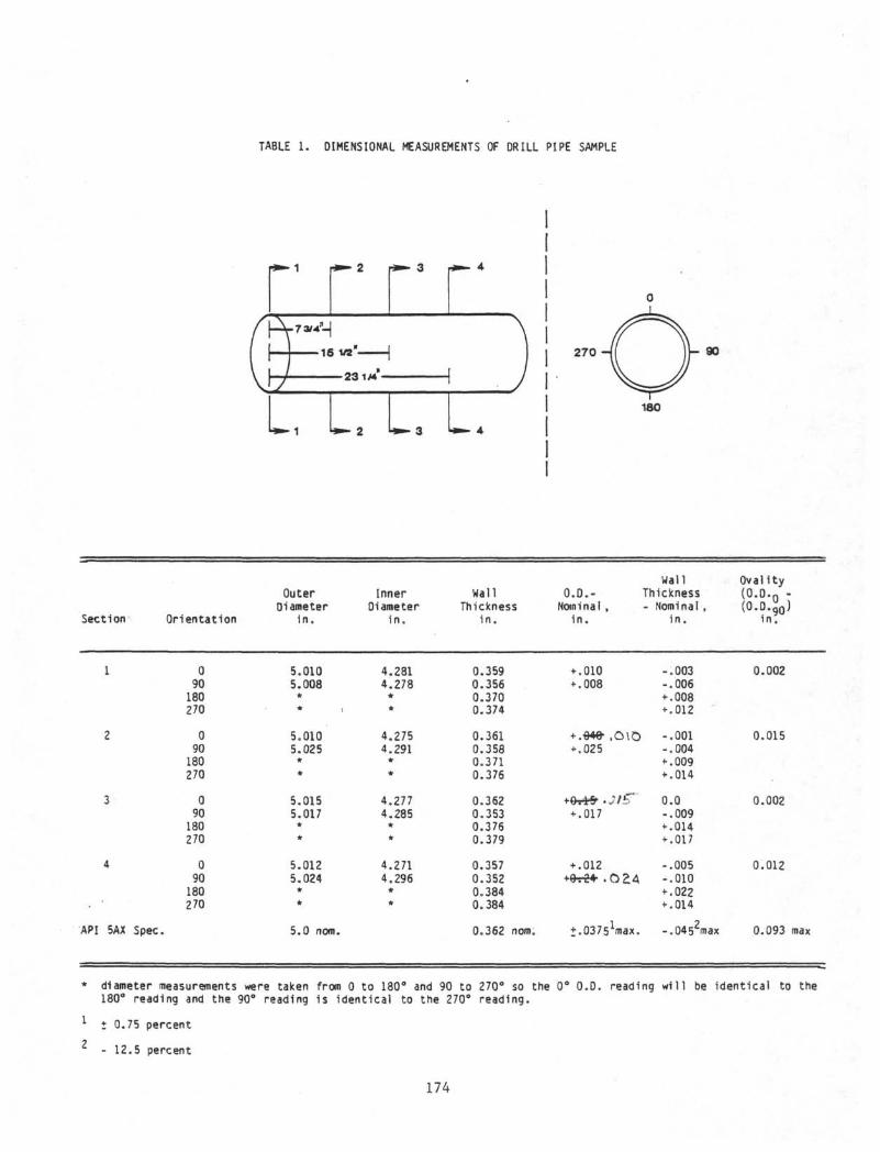
TABLE 1 . DIMENSIONAL MEASUREMENTS OF DRILL PIPE SAMPLE
Uto> 1 i»»- 2 U - 3 > * - 4
270
180
Section
1
2
3
4
API 5AX
Orientation
090
180270
090
180270
090
180270
090
180270
Spec.
OuterDiameter
i n .
5.0105.008
** .
5.0105.025
**
5.0155.017
**
5.0125.024
*
5.0 nom.
InnerDiameter
i n .
4.2814.278
#*
4.2754.291
*• *
4.2774.285
**
4.2714.296
**
WallThickness
i n .
0.3590.3560.3700.374
0.3610.3580.3710.376
0.3620.3530.3760.379
0.3570.3520.3840.384
0.362 nom.
0.0.-Nominal,
i n .
+ .010+ .008
+ .θ4θ• ,O\O+ .025
+ .017
+ .012+frr24 . 0 2 4
+.03751max.
WallThickness- Nominal ,
i n .
-.003-.006+ .008+ .012
-.001-.004+ .009+ .014
0.0-.009+ .014+ .017
-.005-.010+ .022+ .014
-.0452max
Oval i ty( 0 . 0 . Q -
(O.M>)i n .
0.002
0.015
0.002
0.012
0.093 max
* diameter measurements were taken from 0 to 180° and 90 to 270° so the 0° O.D. reading will be identical to the180° reading and the 90° reading is identical to the 270° reading.
1 +0.75 percent
2 - 12.5 percent
174
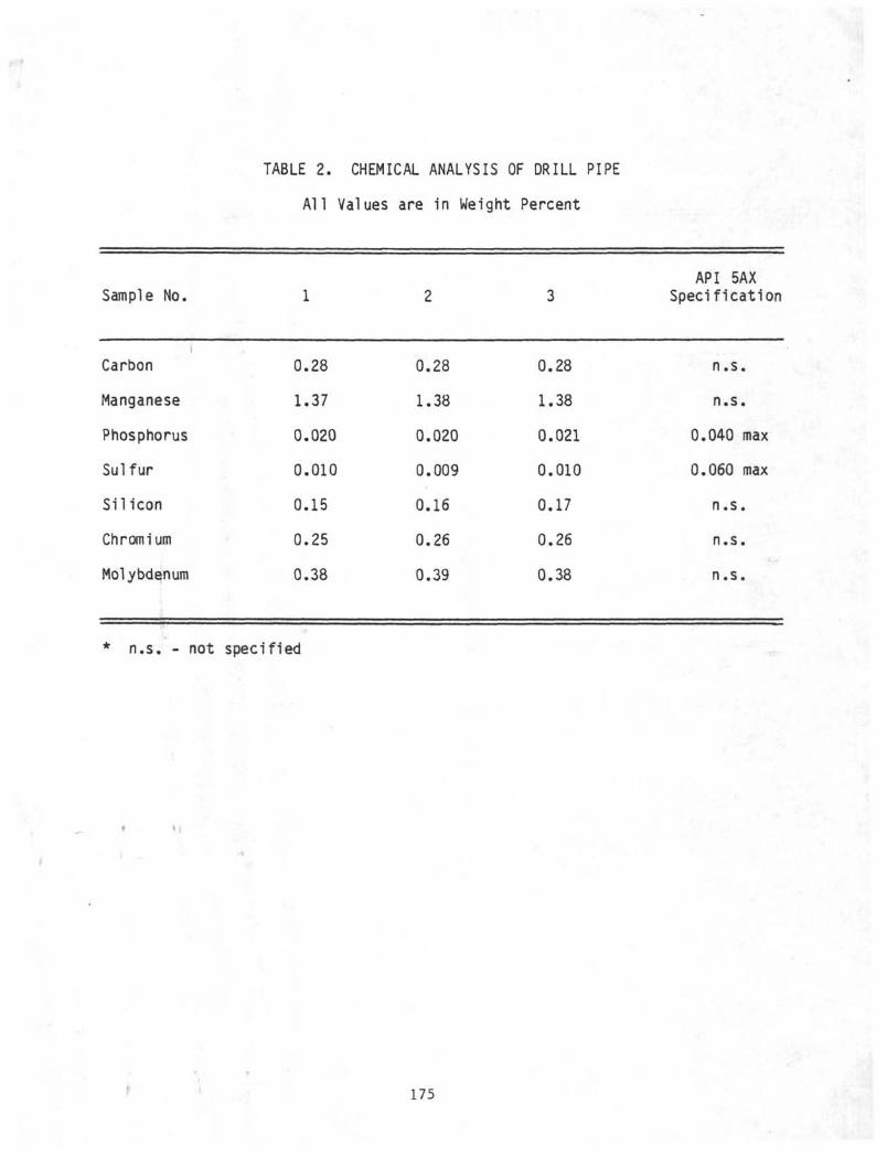
TABLE 2. CHEMICAL ANALYSIS OF DRILL PIPE
All Values are in Weight Percent
Sample No.
1Carbon
Manganese
Phosphorus
Sulfur
Silicon
Chromium
Molybdenum
1
0.28
1.37
0.020
0.010
0.15
0.25
0.38
2
0.28
1.38
0.020
0.009
0.16
0.26
0.39
3
0.28
1.38
0.021
0.010
0.17
0.26
0.38
API 5AXSpecification
n.s.
n.s.
0.040 max
0.060 max
n.s.
n.s.
n.s.
* n.s. - not specified
*
175
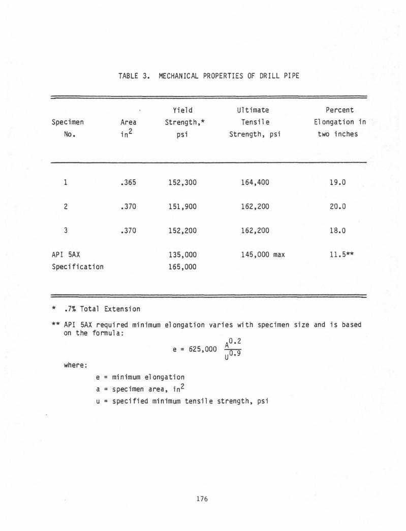
TABLE 3. MECHANICAL PROPERTIES OF DRILL PIPE
Specimen
No.
Area
i n 2
YieldStrength,*
psi
UltimateTensile
Strength, psi
PercentElongation in
two inches
API 5AX
Specification
.365
.370
.370
152,300
151,900
152,200
135,000
165,000
164,400
162,200
162,200
145,000 max
19.0
20.0
18.0
11.5**
* .7% Total Extension
** API 5AX required minimum elongation varies with specimen size and is basedon the formula:
Λ 0 . 2
e = 625,000u u .
where:
e = minimum elongation
a = specimen area, i n 2
u • specified minimum tensile strength, psi
176
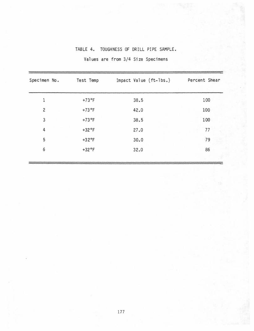
TABLE 4. TOUGHNESS OF DRILL PIPE SAMPLE.
Values are from 3/4 Size Specimens
Specimen No.
1
2
3
4
5
6
Test Ten
+73°F
+73°F
+73°F
+32°F
+32°F
+32°F
Impact Value (ft-lbs.) Percent Shear
38.5 100
42.0 100
38.5 100
27.0 77
30.0 79
32.0 86
177