Embed Size (px)
Citation preview
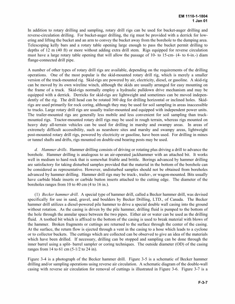
PDHonline Course C301 (3 PDH)
Drill Rig Selection
2012
Instructor: John Poullain, PE
PDH Online | PDH Center5272 Meadow Estates Drive
Fairfax, VA 22030-6658Phone & Fax: 703-988-0088
www.PDHonline.orgwww.PDHcenter.com
An Approved Continuing Education Provider
EM 1110-1-18041 Jan 01
F-3-1
Chapter F-3Drill Rigs and Appurtenant Equipment
3-1. Introduction
A number of commercially available drill rigs and accessories are satisfactory for performing conven-tional drilling and sampling operations or for conducting in situ tests. Although some types of drill rigsare more readily adapted to specific work, the selection of the drill rig and appurtenant equipment isusually based upon the requirements of the geotechnical investigation. Factors which may affect theselection include site accessibility, the type or hardness of material to be sampled and the degree ofdisturbance which is acceptable, equipment availability, time and mobilization costs, the number ofpersonnel required, plant rental costs, etc. A discussion of various types of drill rigs and accessories andappurtenant equipment, including those apparatus to advance and stabilize the borehole, is presented inthis chapter. The discussion of sampling devices is presented in Chapters 5 through 8.
3-2. Drill Rigs
Drill rigs vary from small electric motors to large oil field rigs. The basic elements of an abovegrounddrill rig are the power source or motor, a pump or air compressor for circulating drilling fluid to the bitand cleaning the borehole, a drill head, hoisting drums and cables, a derrick, a mounting platform ordeck, and assorted equipment which includes one or more hammers for driving and removing casing, aportable mud pit, racks for stacking the drill rods and samples, and small tools for coupling or uncouplingand hoisting the drill string, etc. A discussion of the basic components of commonly used drill rigs ispresented in the following paragraphs.
a. Power source. A power source or motor is required to operate a drive weight mechanism forpercussion or churn drilling or to provide rotary motion to turn augers and coring equipment for rotarydrilling operations. Other requirements include operating a winch for raising and lowering the drillingand sampling equipment, providing downward pressure for pushing boring and sampling equipment, orlifting and dropping a hammer to drive casing or sampling equipment. For most drilling and samplingoperations, the power source is the power takeoff from the truck motor on which the drilling machine ismounted or from a separate engine which is assigned or attached as an integral component of the drillingrig. It is estimated that 90 percent of the motors are gasoline or diesel engines and 10 percent arecompressed air or electric motors. A drive train which consists of gears or hydraulic pumps is used toconvert the power supply to speed and torque for hoisting and rotating the drilling equipment. Most unitshave a transmission which allows 4 to 8 speeds for hoisting and drilling. In general, the hoisting capacityof the drill rig governs the depth of the borehole. A rule of thumb for selecting the power source is thehorsepower which is required to hoist the drill rods should be about three times the horsepower which isrequired to turn the drill string. For high elevations, the power loss is about 3 percent for each 300meters (m) or 1,000 feet (ft) above sea level.
b. Fluid pump and accessories. Drilling fluid, such as compressed air or drilling mud, is requiredfor removing the cuttings from the drill bit and the borehole and cooling the bit. Compressed air hasbeen used to a limited extent, especially for water sensitive formations. Clear-water and bentonite-baseddrilling muds are the work horses for geotechnical investigations. Drilling fluids are discussed inChapter 4.
EM 1110-1-18041 Jan 01
F-3-2
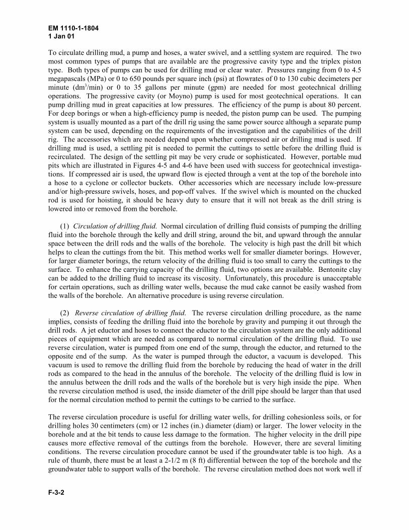
To circulate drilling mud, a pump and hoses, a water swivel, and a settling system are required. The twomost common types of pumps that are available are the progressive cavity type and the triplex pistontype. Both types of pumps can be used for drilling mud or clear water. Pressures ranging from 0 to 4.5megapascals (MPa) or 0 to 650 pounds per square inch (psi) at flowrates of 0 to 130 cubic decimeters perminute (dm /min) or 0 to 35 gallons per minute (gpm) are needed for most geotechnical drilling3
operations. The progressive cavity (or Moyno) pump is used for most geotechnical operations. It canpump drilling mud in great capacities at low pressures. The efficiency of the pump is about 80 percent.For deep borings or when a high-efficiency pump is needed, the piston pump can be used. The pumpingsystem is usually mounted as a part of the drill rig using the same power source although a separate pumpsystem can be used, depending on the requirements of the investigation and the capabilities of the drillrig. The accessories which are needed depend upon whether compressed air or drilling mud is used. Ifdrilling mud is used, a settling pit is needed to permit the cuttings to settle before the drilling fluid isrecirculated. The design of the settling pit may be very crude or sophisticated. However, portable mudpits which are illustrated in Figures 4-5 and 4-6 have been used with success for geotechnical investiga-tions. If compressed air is used, the upward flow is ejected through a vent at the top of the borehole intoa hose to a cyclone or collector buckets. Other accessories which are necessary include low-pressureand/or high-pressure swivels, hoses, and pop-off valves. If the swivel which is mounted on the chuckedrod is used for hoisting, it should be heavy duty to ensure that it will not break as the drill string islowered into or removed from the borehole.
(1) Circulation of drilling fluid. Normal circulation of drilling fluid consists of pumping the drillingfluid into the borehole through the kelly and drill string, around the bit, and upward through the annularspace between the drill rods and the walls of the borehole. The velocity is high past the drill bit whichhelps to clean the cuttings from the bit. This method works well for smaller diameter borings. However,for larger diameter borings, the return velocity of the drilling fluid is too small to carry the cuttings to thesurface. To enhance the carrying capacity of the drilling fluid, two options are available. Bentonite claycan be added to the drilling fluid to increase its viscosity. Unfortunately, this procedure is unacceptablefor certain operations, such as drilling water wells, because the mud cake cannot be easily washed fromthe walls of the borehole. An alternative procedure is using reverse circulation.
(2) Reverse circulation of drilling fluid. The reverse circulation drilling procedure, as the nameimplies, consists of feeding the drilling fluid into the borehole by gravity and pumping it out through thedrill rods. A jet eductor and hoses to connect the eductor to the circulation system are the only additionalpieces of equipment which are needed as compared to normal circulation of the drilling fluid. To usereverse circulation, water is pumped from one end of the sump, through the eductor, and returned to theopposite end of the sump. As the water is pumped through the eductor, a vacuum is developed. Thisvacuum is used to remove the drilling fluid from the borehole by reducing the head of water in the drillrods as compared to the head in the annulus of the borehole. The velocity of the drilling fluid is low inthe annulus between the drill rods and the walls of the borehole but is very high inside the pipe. Whenthe reverse circulation method is used, the inside diameter of the drill pipe should be larger than that usedfor the normal circulation method to permit the cuttings to be carried to the surface.
The reverse circulation procedure is useful for drilling water wells, for drilling cohesionless soils, or fordrilling holes 30 centimeters (cm) or 12 inches (in.) diameter (diam) or larger. The lower velocity in theborehole and at the bit tends to cause less damage to the formation. The higher velocity in the drill pipecauses more effective removal of the cuttings from the borehole. However, there are several limitingconditions. The reverse circulation procedure cannot be used if the groundwater table is too high. As arule of thumb, there must be at least a 2-1/2 m (8 ft) differential between the top of the borehole and thegroundwater table to support walls of the borehole. The reverse circulation method does not work well if
EM 1110-1-18041 Jan 01
F-3-3
cobbles larger than the inside diameter of the drill pipe are encountered. If too many cobbles areencountered and cannot be removed from the boring, the bit should be withdrawn and a bucket auger canbe used to clean the bottom of the hole. When clay is drilled, the cuttings may tend to build on the bladesof the bit because of ineffective cleaning due to the low velocity of the drilling fluid past the bit. If thisproblem occurs, the bit cannot be advanced. It must be pulled and cleaned before additional drilling canbe done.
c. Drill head. Perhaps the single most important component of the drilling rig is the drive head ordrill head. Its primary functions include rotating and hoisting or pull down of the drilling tools. Somedrill heads have the capability of being rotated from vertical to horizontal for drilling vertical or inclinedholes. Drill rigs may also be equipped with a special �gate opening� drive head which can be swungaside to permit removal of drill rods. The principal disadvantage of this type of drive head is thelooseness or wobble which may develop as a result of wear of the system. The gate opening drill head isbeing replaced with a solid drill head sliding table which can be moved forward or back to permitremoval of the drill rods.
Drilling tools are connected to the drill head by a fluted or square thick-walled pipe or �kelly� rod whichruns through the drive head. The kelly is designed to move up and down through the drill head as it isrotated. Torque is applied to the kelly through bevel gears in the drive head. The speed of rotation variesover a wide range. The top of the kelly is fitted with a swivel which permits the drilling fluid to bepumped through the kelly and drill rods to the drilling and sampling tools. Some types of swivels havebeen designed for use in conjunction with the pulldown mechanisms on drill rigs.
Two basic choices for controlling the rate of advance or feed of the drilling or sampling apparatus areavailable. The screw feed advances the spindle through gears and a feed nut. This technique forces thespindle downward at a set ratio of advance to rotation of the drill string; typically, three or four ratios areavailable. The hydraulic drive and the chain or cable pulldown techniques are more flexible and reliableand are gradually replacing the screw feed method. In general, with other factors being equal, thehydraulic drive mechanism is capable of developing greater thrusts than chain- or cable-pulldown mech-anisms.
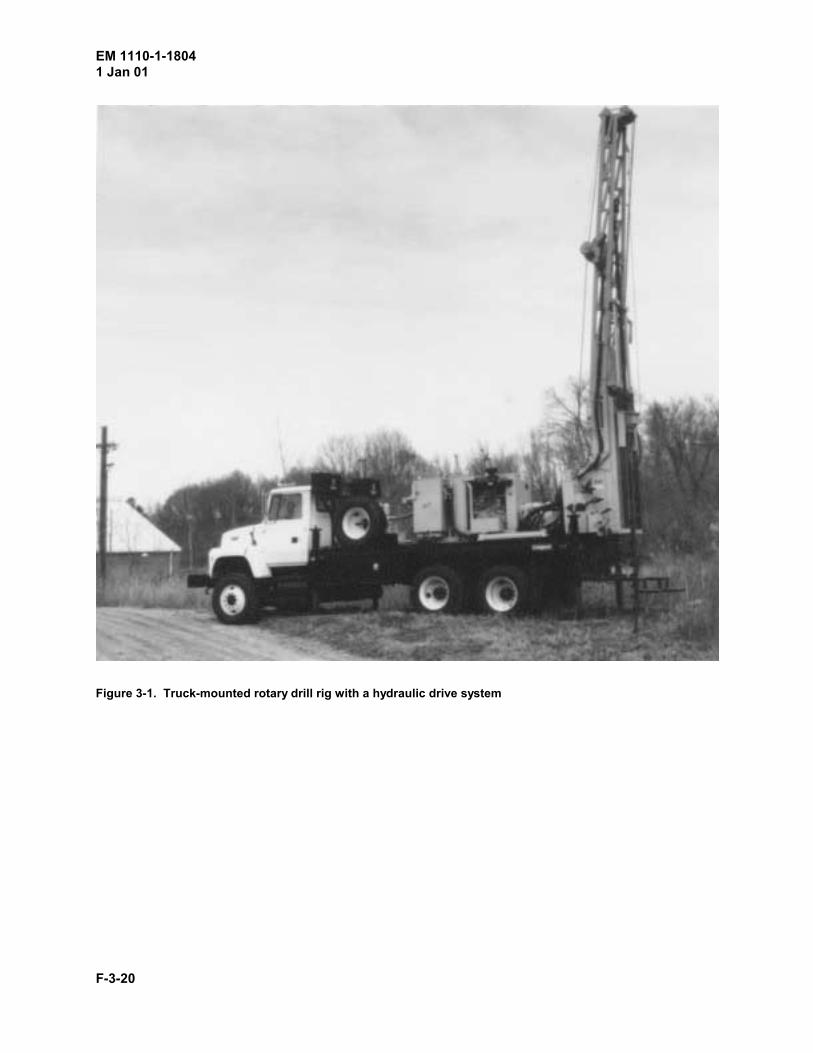
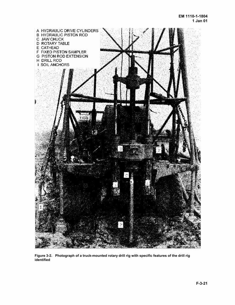
(1) Hydraulic drive. Oil-operated hydraulic drive systems on drill rigs are the most satisfactorydrive mechanisms for conducting undisturbed sampling operations. Most hydraulic drive systems consistof two cylinders which are attached to the drive head. A manual or automatic chuck, which is located inthe drive head, consists of three or four jaws which grip the kelly to transfer thrust from the hydrauliccylinders to the drill rods. During drilling operations using a manual chucking system, the hydrauliccylinders are activated to raise the drive head, the kelly is chucked, and a drive is made. When the drivehead has been moved a distance equal to the stroke of the hydraulic cylinders, which is usually 0.6 to 0.9m (2 to 3 ft) of travel, the kelly is unchucked, the cylinders are raised, and the kelly is rechucked foranother drive. If an automatic chuck is used, the chuck will only grip the kelly during the downwardmovement of the drivehead. Figure 3-1 shows a typical truck-mounted rotary drill rig with an hydraulicdrive system. Figure 3-2 identifies a number of specific elements, such as cathead, jaw chuck, and rotarytable, on a typical truck-mounted rotary drill rig.
(2) Chain pulldown. Drill rigs equipped with chain pulldown drive mechanisms are satisfactory forundisturbed sampling of some soils. The chain pulldown system consists of chains located on each sideof the kelly which are connected to sprocket wheels located on the deck of the rig. The sprocket wheelsare driven through a hydraulic transmission. The chain pulldown mechanism applies thrust through ayoke which is attached to the water swivel at the top of the kelly. Therefore, a special adaptor is required
EM 1110-1-18041 Jan 01
F-3-4
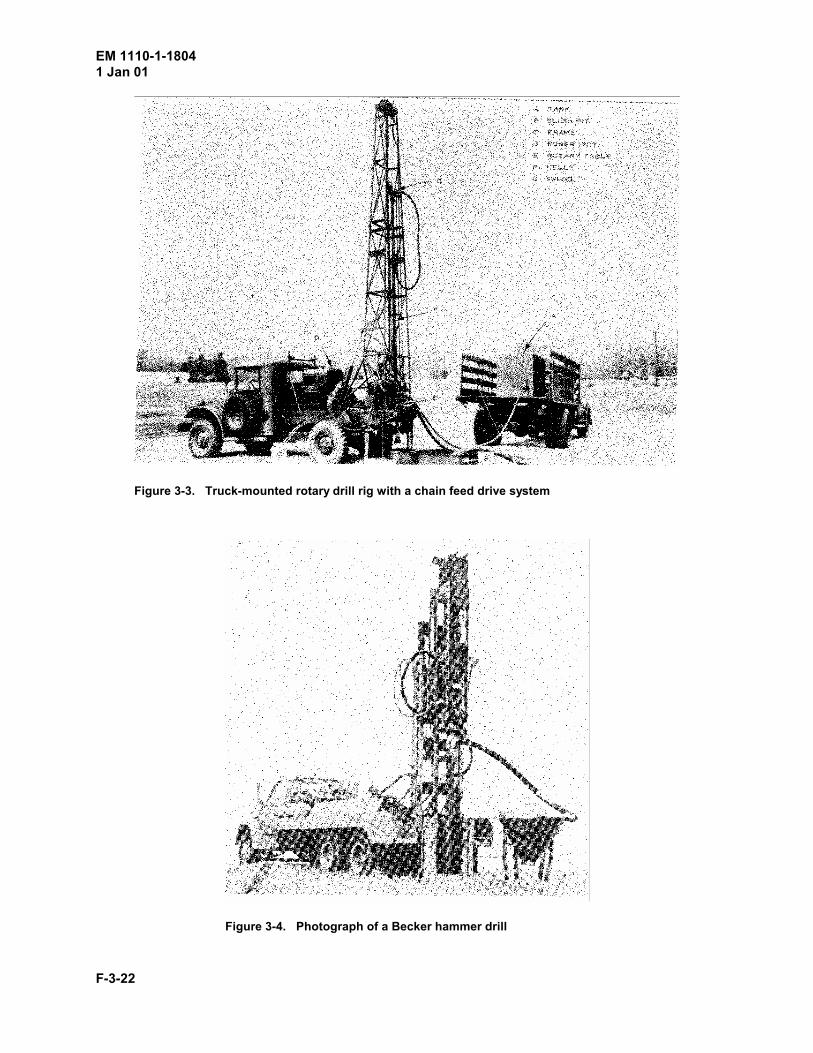
to allow the piston rod extensions to pass through the swivel and be clamped in the drill rig mast when afixed piston sampler is used. As compared to hydraulic pulldown systems, chain pulldown systems havea much longer stroke, i.e., 6 m (20 ft) or more. Figure 3-3 shows a truck-mounted rotary drill rig with achain feed drive system.
(3) Cable pulldown. Undisturbed samples are seldom obtained with a cable pulldown arrangementon a drill rig, although cable pulldown mechanisms have sometimes been used to achieve long sampledrives. Generally, cable pulldown arrangements are used in remote, inaccessible areas in conjunctionwith a block and tackle or a hand-operated winch to apply the driving power.
d. Hoists. Hoisting drums and cables are needed to raise or lower drilling tools and casing. Hoistson most drill rigs traditionally consist of a single wireline drum with cables and sheaves. These systemsare frequently supplemented on a part-time basis by the cathead and rope system or a special wirelinehoist for recovering the inner core barrel for wireline drilling.
The typical drum hoist is controlled by a brake and a clutch. The cable on the drum hoist must reachfrom the hoist to the sheave on the derrick and back to the drill deck. Its advantages include a high gearreduction which allows for powerful, low-speed hoisting capabilities. This feature permits feathersmooth lifting characteristics for lowering or raising the drill string without jarring or jerking. However,the drum hoist system is not acceptable for lifting and dropping the hammer for the Standard PenetrationTest (SPT) that is discussed in Appendix B (Appendix G of the Geotechnical Investigations manual).
The cathead and rope system is handy for driving casing, lifting and dropping the hammer for the SPT,picking up heavy accessories, and for conducting wash borings. It consists of a cathead, a sheave on aderrick, and a manila rope. This system can be used to lift moderately heavy objects at medium liftingrates.
The wireline hoist system which is used for wireline drilling is a high-speed, low-capacity system. Thewireline hoist system must be equipped with sufficient cable to reach from the hoist to the sheave on thederrick to the bottom of borehole.
e. Derrick. A derrick is a two- to four-legged frame or mast which is equipped with a sheave forhoisting and handling tools in and out of the borehole. It can also supplement as a frame for stackingdrill rods during trips. The design and height of the derrick is usually selected based upon the length of adrill rod and the type of drilling which is normally conducted. For shallow borings, the drill pipe isfrequently 3 m (10 ft) sections. For deeper borings, longer drill pipe, i.e., 6 to 9 m (20 to 30 ft), isnormally used. For angled holes, a derrick with an adjustable frame or legs may be desirable. Prior totransport, the derrick is folded down on the drill rig; for most rigs, this operation is performed by the useof hydraulic cylinders.
f. Mounting platform. With the exception of lightweight portable units which are used in remoteareas, drilling rigs are usually affixed to a mounting platform or deck to permit leveling of the drill headbefore drilling and to prevent movement out of alignment during drilling operations. The platformshould be rugged enough to permit the use of the full capacity of the drill.
Several types of drill mounting platforms can be used, depending on the terrain, logistics, and depth ofhole. On land, the drill may be mounted on a platform of reinforced timber cribbing or affixed to a truckor trailer. For rugged terrain, a smaller version of the truck-mounted rig may be mounted on skids anddragged. Lightweight units, such as the hand-held vibratory sampling devices or hand-held augers, can
EM 1110-1-18041 Jan 01
F-3-5
be mounted on casing or a framework of drill pipe which has been driven into the overburden. Land-type drill rigs mounted on barges, floating platforms supported by pontoons of oil drums, or the fixedplatforms supported by piles or spuds are used for most nearshore marine work. Although a barge orfloating platform is more common than a fixed platform, the disadvantage of the barge or float is that itmoves with tide and wave action, whereas the disadvantage of the fixed drilling platform is its expense.
g. Ancillary equipment. A number of small tools and miscellaneous equipment are needed for thedrill rig. Driving weights, such as the 63.5 kilogram (kg) or 140 pound (lb) hammer for the SPT test andperhaps a larger hammer, i.e., 113 to 181 kg (250 to 400 lb) range, for driving and removing casing areintegral components of the drill rig. Fishing tools for recovering drilling equipment which has been lostin the borehole, bypass and pop-off valves for the fluid circulation system, assorted safety hooks andhoisting tools, tools for coupling and uncoupling drill strings or augers, and spiders and forks for holdingsections of drill rods or augers in the borehole should always be carried on the drill rig. A short piece ofcasing which can be driven into the ground prior to commencing the drilling operations should also becarried on the drill rig; the casing can be used as a collar to prevent erosion or sloughing at the top of theborehole caused by the action of the drilling fluid. Other equipment may include racks for stacking drillrods and samples. A number of small tools such as hand-held hammers, punches, adjustable wrenches,pipe wrenches, pliers, vise grips, screwdrivers, allen wrenches, and hacksaws and hacksaw blades, aswell as hard hats, first aid kits, and this manual, should always be carried on the drill rig.
3-3. Types of Drills
Drill rigs are designed to perform a certain type of operation. Rotary, churn, and percussion drill rigs arethe most common, although a number of other types of rigs have been designed and developed to performsite-specific tasks, such as drilling shot holes in quarries. Of these rigs, the rotary drill rig is widely usedfor geotechnical engineering investigations, whereas churn and percussion rigs are used more extensivelyfor drilling water wells and for construction operations, such as drilling holes for cast-in-place piles.
a. Drills for wash borings. The wash boring refers to a process by which the borehole is advancedby a combination of chopping and jetting to break the formation and washing to remove the cuttings.The principal use of the wash boring method is to advance the hole between samples. The cuttings arenot acceptable for sampling because of the breakdown of the particles due to the chopping action, theloss of fines during transport of the cuttings to the surface, and segregation of the cuttings in the sumptank. However, an experienced operator may be able to distinguish changes of stratigraphy by the actionof the chopping bit as well as by changes of the characteristics of the cuttings.
The equipment to advance holes by the wash boring method consists of a motor which is used to drive acathead for raising and lowering the tools in the borehole, a derrick with a sheave through which a ropefrom the cathead is passed to the drilling tools, and a water pump for jetting and washing the cuttingsfrom the borehole. During drilling operations, the drill string is lowered into the borehole. Drilling fluidis pumped under pressure through the drill rods and bit to the bottom of the hole as the chopping bit israised and dropped. Each time the rods are dropped, they are rotated either manually by a wrench orlever or mechanically by the rotary drill-rig drive. The rotation of the drill rods helps to break thematerial at the bottom of the borehole. The resulting cuttings are carried to the surface by the drillingfluid which flows in the annulus between the drill pipe and the walls of the hole. Cuttings which are notremoved from the borehole when the circulation of the drilling fluid is stopped tend to settle and becomethe upper part of the next sample. The hole can usually be cleaned satisfactorily by raising the drill stringslightly and circulating the drilling fluid until it is free of cuttings. Casing may be used, if necessary, tostabilize the walls of the borehole.
EM 1110-1-18041 Jan 01
F-3-6
b. Churn drills. The churn drill was one of the first types of drilling machines to be manufactured.Churn drills are used extensively in the water well industry. They are economical to operate and areuseful for advancing a boring through boulder or rubble zones and can be used for obtaining disturbeddrive samples in soil and soft shale. However, they can not be adapted to undisturbed samplingoperations.
The churn drill has no rotary features. Churn drilling which is often called cable-tool drilling is accom-plished by the up and down hammering or churning action of a chisel-shaped or a cross-shaped drill bitfor spudding or chopping. The drill bit is attached to a heavy steel weight on the drill string whichfrequently exceeds 450 kg (1,000 lb). The drill string is suspended by a cable and tends to act like aplumb bob when it is raised and dropped. The churning action is accomplished by a walking beam on thedrill rig. Churn drills may be truck or trailer mounted and are generally powered by gasoline or dieselengines.
The procedures which are used to advance the borehole depend on the location of the water table and thetype of soil which is encountered. Above the water table, a small amount of water should be poured intothe borehole to form a slurry with the cuttings. When the carrying capacity of the slurry is reached, it canbe removed by bailing. After the cuttings have been removed, more water is added to the borehole andthe procedure is repeated. When drilling below the water table, it is not necessary to add water for theslurry. For clays, a small amount of sand may be placed in the borehole to enhance the cutting action ofthe bit. For sands, clay may be placed in the borehole to enhance the carrying capacity of the slurry. Forunstable soils, casing may be added as the borehole is advanced; in soft or cohesionless soils, theborehole can frequently be advanced by bailing inside of the casing. The diameter of the boreholetypically ranges from 10 to 30 cm (4 to 12 in.).
To obtain a sample, the drill bit and the short-stroke drilling jar are replaced with a hollow steel barreland long-stroke fishing jar for drive sampling. The long-stroke jars provide a slip joint link in the drillstring that allows the top half of the jar and the drill string to be lifted and dropped while the bottom halfof the jar and the sampler remain stationary. Holes which are drilled and sampled tend to be verticalbecause of the plumb bob action of the drill string.
c. Rotary drills. Rotary drill rigs are the workhorses of most geotechnical engineering drilling andsampling operations. In general, boreholes are advanced by rotary action coupled with downwardpressure applied to the drill bit plus the cleaning action of the drilling fluid. Samples may be obtained byrotary coring or by pushing a thin-walled tube into the foundation material at the desired depth. Therated capacity of rotary drill rigs, unless otherwise noted, is usually based on the performance in a 75-mmor a 3-in.-diam (NX) hole. Most drill rigs are mounted on a truck, trailer, tractor, or all-terrain vehicle oron skids, although post-mounted drill rigs or portable units are sometimes used in remote or inaccessibleareas.
Most truck-mounted rotary drill rigs can be used for drilling, sampling, and in situ testing. Generally,rotary drill rigs are driven by the power takeoff from the truck engine, although some drill rigs areequipped with independent engines. Two general types of pulldown mechanisms are normally used.Truck-mounted rotary drill rigs equipped with a chain pulldown drive mechanism are capable of drillingto depths of 60 to 300 m (200 to 1,000 ft). Hydraulic feed drive rotary drill rigs are capable of drilling todepths of 150 to 750 m (500 to 2,500 ft). A total thrust capacity of approximately 45 kilonewtons (kN)or 10,000 lb is required for undisturbed sampling in very stiff materials. Although the total thrust onchain pulldown rigs may not be sufficient for undisturbed sampling in resistant soils, these rigs can beused for disturbed sampling and vane shear testing.
EM 1110-1-18041 Jan 01
F-3-7
In addition to rotary drilling and sampling, rotary drill rigs can be used for bucket-auger drilling andreverse-circulation drilling. For bucket-auger drilling, the rig must be provided with a derrick for low-ering and lifting the bucket and an arm to convey the bucket away from the borehole to the dumping area.Telescoping kelly bars and a rotary table opening large enough to pass the bucket permit drilling todepths of 12 m (40 ft) or more without adding extra drill stem. Rigs equipped for reverse circulationmust have a large rotary table opening that will allow the passage of 10- to 15-cm- (4- to 6-in.-) diamflange-connected drill pipe.
A number of other types of rotary drill rigs are available, depending on the requirements of the drillingoperations. One of the most popular is the skid-mounted rotary drill rig, which is merely a smallerversion of the truck-mounted rig. Skid-rigs are powered by air, electricity, diesel, or gasoline. A skid-rigcan be moved by its own wireline winch, although the skids are usually arranged for easy mounting onthe frame of a truck. Skid-rigs normally employ a hydraulic pulldown drive mechanism and may beequipped with a derrick. Derricks for skid-rigs are lightweight and sometimes can be moved indepen-dently of the rig. The drill head can be rotated 360 deg for drilling horizontal or inclined holes. Skid-rigs are used primarily for rock coring, although they may be used for soil sampling in areas inaccessibleto trucks. Large rotary drill rigs are usually trailer-mounted and equipped with independent power units.The trailer-mounted rigs are generally less mobile and less convenient for soil sampling than truck-mounted rigs. Tractor-mounted rotary drill rigs may be used in rough terrain, whereas rigs mounted onheavy duty all-terrain vehicles can be used for drilling in marshy and swampy areas. In areas ofextremely difficult accessibility, such as nearshore sites and marshy and swampy areas, lightweightpost-mounted rotary drill rigs, powered by electricity or gasoline, have been used. For drilling in minesor tunnel shafts and drifts, rigs mounted on double-end bearing posts may be used.
d. Hammer drills. Hammer drilling consists of driving or rotating plus driving a drill to advance theborehole. Hammer drilling is analogous to an air-operated jackhammer with an attached bit. It workswell in medium to hard rock that is somewhat friable and brittle. Borings advanced by hammer drillingare satisfactory for taking disturbed samples provided that the material in the bottom of the borehole canbe considered as representative. However, undisturbed samples should not be obtained from boreholesadvanced by hammer drilling. Hammer drill rigs may be truck-, trailer-, or wagon-mounted. Bits usuallyhave carbide blade inserts or carbide button inserts attached to the cutting edge. The diameter of theboreholes ranges from 10 to 40 cm (4 to 16 in.).
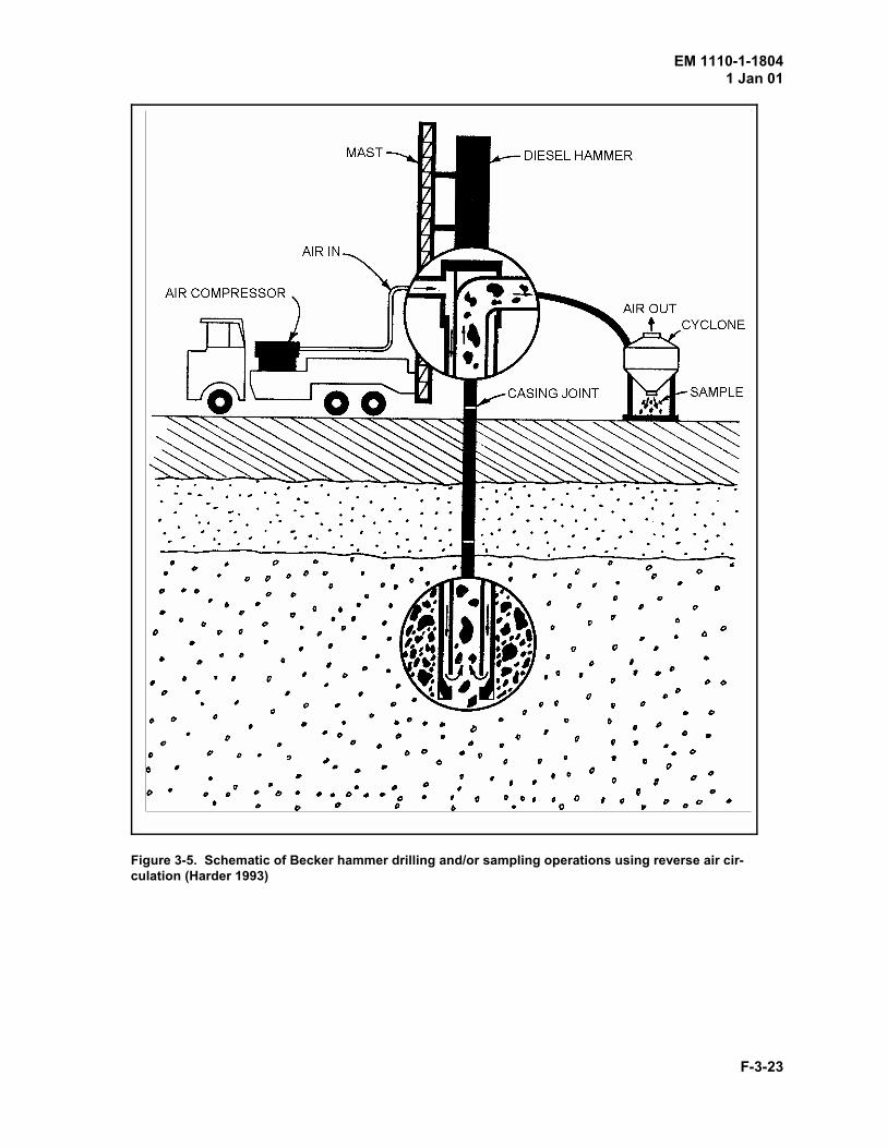
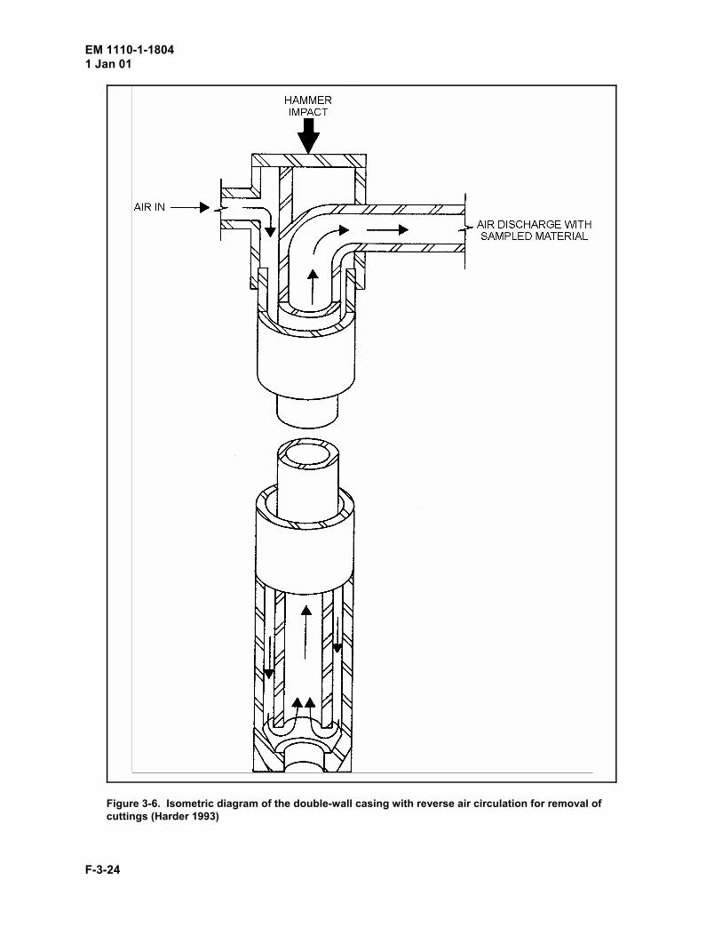
(1) Becker hammer drill. A special type of hammer drill, called a Becker hammer drill, was devisedspecifically for use in sand, gravel, and boulders by Becker Drilling, LTD., of Canada. The Beckerhammer drill utilizes a diesel-powered pile hammer to drive a special double wall casing into the groundwithout rotation. As the casing is driven by the pile hammer, drilling fluid is pumped to the bottom ofthe hole through the annular space between the two pipes. Either air or water can be used as the drillingfluid. A toothed bit which is affixed to the bottom of the casing is used to break material with blows ofthe hammer. Broken fragments or cuttings are returned to the surface through the center of the casing.At the surface, the return flow is ejected through a vent in the casing to a hose which leads to a cycloneor to collector buckets. The cuttings which are collected can be observed to give an idea of the materialswhich have been drilled. If necessary, drilling can be stopped and sampling can be done through theinner barrel using a split- barrel sampler or coring techniques. The outside diameter (OD) of the casingranges from 14 to 61 cm (5-1/2 to 24 in).
Figure 3-4 is a photograph of the Becker hammer drill. Figure 3-5 is a schematic of Becker hammerdrilling and/or sampling operations using reverse air circulation. A schematic diagram of the double-wallcasing with reverse air circulation for removal of cuttings is illustrated in Figure 3-6. Figure 3-7 is a
EM 1110-1-18041 Jan 01
F-3-8
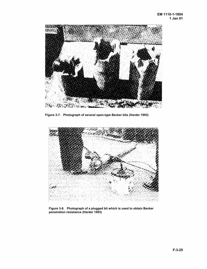
photograph of several open bits. Typically, the OD of Becker bits ranges from 14 to 23 cm (5.5 to 9.0in.), although the 17-cm (6.6-in.) diameter is commonly used for the Becker penetration test (BPT).Figure 3-8 is a photograph of a plugged bit which is being connected to the double-wall casing. Pluggedbits are used to obtain Becker penetration resistance which is discussed in Appendix C (Appendix H ofGeotechnical Investigations manual). Soil, which is collected by a cyclone during drilling operations, isshown in Figure 3-9.
The elements of the Becker hammer drill include an air compressor, mud pump, either a double- orsingle-acting diesel pile hammer, rotary drive unit, hydraulic hoist, casing puller, mast, and cyclone. Thedouble-wall threaded casing is specially fabricated from two heavy pipes which act as one unit. It hasflush joints and tapered threads for making and breaking the casing string. The standard casing is 14.0-to 16.8-cm (5-1/2- to 6-5/8-in.) OD by 8.3- to 8.7-cm (3-1/4- to 3-7/16-in.) inside diameter (ID). Thechisel-type bits are made of a tempered steel and nickel alloy. The principal advantage of the Beckerhammer drill includes a rapid and inexpensive method for drilling bouldery materials. The principaldisadvantage of this method of drilling is that when compressed air is used, the pressure at the bottom ofthe casing is reduced far below the hydrostatic pressure from the groundwater table. Hence, the flow ofgroundwater into the borehole can disturb the material at the bottom of the boring. If a boulder isencountered, sand surrounding the boulder may be sucked into casing. As a result, the sample is nonrep-resentative, and the recovery ratio could exceed 100 percent.
(2) Becker CRS drill. A modification of the Becker hammer drill is the Becker CRS drill. This drilluses twin-tube drill rods with a modified tri-cone roller bit at the bottom of the rods. To advance theborehole, the drill string is hammered and simultaneously rotated. Air is normally used as the drillingfluid, although water or an air-water mixture can be used. The drill bits have an open center to obtainsamples. The Becker CRS drill is a fast, economical method for drilling holes or casing throughoverburden to obtain rock. The Becker processes are patented. Work can be performed under contractwith Becker Drilling, LTD.
(3) Eccentric reamer system. Another patented hammer drilling system is the eccentric reamer, orODEX, system. Drilling action consists of rotation plus percussion. The principal drilling equipmentconsists of a pilot bit with a bearing surface on which the reamer rides and an eccentric reamer which isused to drill the borehole larger than the OD of the casing. Both the reamer and the pilot bit are fittedwith carbide cutting inserts for drilling purposes. An eccentrically placed hole in the reamer permits thereamer to be twisted in or out (with respect to the pilot bit shaft), depending on the direction of rotationof the shaft. Stop lugs are used to hold the reamer once it has been positioned. Foam drilling fluid issometimes used to lubricate the sidewalls of the borehole so that the casing, which follows the bit andreamer, will slide more easily into the borehole. Foam may also enhance the removal of cuttings fromthe borehole.
Two types of air hammers are available. A downhole hammer is attached directly to the pilot bit. Forthis system, a special casing shoe is required to transfer the energy from the hammer to the casing to�pull� it down. Center rods which are the same length as the casing sections are used to rotate the pilotbit and reamer during drilling operations. Rotation of the casing is prevented, although the hammer,casing, and drill bits move downward in unison. If a top hammer drive is used, the hammer is attached atthe top of the casing string and is connected to the pilot bit and reamer by drill rods. During drillingoperations, all components are moved downward in unison. However, only the pilot bit and reamer arerotated; rotation of the casing is prevented.
EM 1110-1-18041 Jan 01
F-3-9
To operate, the bit is rotated clockwise to swing the reamer to the correct position; a sharpcounterclockwise rotation of the drill bit through the drill string swings the reamer back over the pilot bitfor removal from the borehole. No samples are obtained by this method of drilling, although a roughidea of the material can be obtained by observing the cuttings. This method of drilling is useful forpenetrating loose overburden material to access more competent underlying formations.
e. Auger drills. Auger rigs employ a basic rotary drilling technique in conjunction with varioustypes of augers to advance the borehole. The parts of an auger rig are virtually the same as rotary drillingrigs except a kelly is not needed. The auger is attached directly to the rotary drive or spindle. When anauger rig is needed for rotary work, a chuck is installed above or below the spindle and a kelly rod isinserted through the hollow rotary spindle. Most auger rigs use an hydraulic pulldown drive mechanism.These rigs are usually equipped with long or telescoping hydraulic cylinders which permit a drive orstoke of 1.8 m (5 ft) or more.
Large auger rigs are usually mounted on a crane or truck. Augers and belling buckets are used fordrilling large-diameter holes. If a crane is used, no downward force can be applied to the auger. Theborehole is advanced by relying on the weight of the bucket plus the digging of the teeth. Drillingoperations are controlled from the cab of crane. If a truck-mounted rig is used, drilling operations arecontrolled from a position on or at the end of the rig. Downward force is applied by a chain or hydraulicpulldown mechanism. During drilling operations, the auger is pulled to the surface after it has beenfilled. To empty, the drill is pivoted on a turntable on the truck bed. When it has been moved away fromthe borehole, the auger is spun rapidly to discharge the cuttings.
Small motorized auger drills are used in inaccessible areas. They are useful for obtaining a limitednumber of holes in a hurry. These drills are handheld or can be mounted on a mobile stand. Mostportable drills are capable of reverse augering.
The bucket auger rig, which is a form of the rotary drill rig, uses a ring gear drive to supply rotary torqueto the bucket. The ID of the ring must be sufficient to allow the bucket to pass through. The drive bar inwhich the kelly slides fits into two slots at 180 deg apart on the drive ring. Torque from the kelly istransmitted through the drive bar to the drive ring. For this type of drilling rig, the kelly is usually squarewith two or three telescoping sections which can be extended to 25 m (82 ft) or more. To fill, the bucketis rotated. When it is full, the bucket is raised and pulled through the drive ring by a cable. A dump armis used to pull bucket away from the rig. A photograph of a bucket auger drill in operation is presented inFigure 3-10. A variety of types of bucket augers are available for specific tasks. A discussion of thetypes of buckets is presented in paragraph 7-2d.
f. Other drills. A large number of other drills, including electric arc and electric beam drills,explosive and jet drills, implosion drills, and laser drills are in experimental stages of development andtherefore are not discussed herein. Details of these drills are reported by Maurer (1980) and otherreferences. Only those drills which are currently used for civil engineering purposes are discussed.
(1) Remote control drill. Drilling by remote control methods has received much interest, especiallyfor investigations of sites such as munitions dumps or areas which are suspected of being contaminatedby hazardous or toxic wastes. For remote control drilling operations, air cylinders or electric motors areattached to the operating levers of the rig and to the remote console. The function of the remote controlsystem is to advance or withdraw drilling tools or samplers from the borehole. Other drilling functionssuch as making or breaking the drill string must be performed by the crew at the rig.
EM 1110-1-18041 Jan 01
F-3-10
(2) Electric motor drill. Electric motor rotary drills are available for use with thin-wall diamondcore bits for obtaining samples of concrete and rock from difficult locations. These portable drills can bemounted on a pipe or casing or attached to a rack and base. They can also be bolted to a wall or ceiling,such as in a tunnel or drift. Although these drills are generally not adaptable for soil samplingoperations, they can be used to drive small augers. This type of drill is also available in air or gas drivenmodels.
(3) Air track drill. Air track drills are used for drilling shot holes in quarries. These maneuverabledrills are operated by air motors and move about on steel tracks. They are air-operated and usepercussion plus rotary drilling techniques. These drills employ a chain pulldown feed mechanism foradvancing the borehole. Air track drills can be used to drill blast holes at any angle.
3-4. Accessories and Appurtenant Equipment
Various types of accessories and appurtenant equipment are required for soil sampling and drilling. Thisequipment includes, but is not limited to, drill rods, drill bits, casing, portable sumps or mud pits, augers,bailers and sand pumps, and miscellaneous pieces of small equipment. The following paragraphsdescribe the equipment normally required, excluding hand tools.
It should be noted that a great deal of time and consequently, money can be saved during the actualdrilling operations if a little forethought is given to the physical layout of the site and the placement ofthe equipment in a convenient manner to permit easy access during the drilling operations. Besides thework area required for the drill rig and circulation system, consideration should also be given to thestorage and/or stacking of drill rods, casing, and other miscellaneous equipment as well as work areas forinspection, logging, and temporary storage of samples. No standard configurations are offered, however,as the layout of each site is dependent on the equipment involved and the terrain. It is suggested that thedriller and engineer or geologist should inspect and plan the layout of the site before drilling begins.
a. Standard nomenclature. Two standards are used for the designation of drilling tools, includingdrill rods, casing, drill bits, and core barrels. Metric standards predominate in Europe. The DiamondCore Drill Manufacturers Association (DCDMA) standards were developed in United States, Canada,England, South Africa, and Australia. It is estimated that DCDMA standards account for about 80percent of the equipment which is sold throughout the world (Acker 1974). Therefore, only the DCDMAstandards are discussed herein.
A two- or three-letter designation is used to describe drilling equipment according to DCDMA standards(Diamond Core Drill Manufacturers Association, Inc. 1991). The first letter in the DCDMA standarddesignation, such as E, A, or N, indicates the approximate borehole diameter for standard steel drill pipe.The second letter, i.e., X or W, is the group standardization of key diameters and the designstandardization of dimensions affecting interchangeability. For example, �W� is used to designate flushjoint casing, whereas �X� is used to designate flush coupled casing. The �X� casing is relativelylightweight tubing with fine threads and is not flush along its ID. The �W� casing is heavier walled thanthe �X� casing and is machined with coarse threads. It has a box thread at one end and a pin thread at theopposite end. Box and pin threads on tubular members refer to the placement of threads on the insidesurface and threads on the outside surface, respectively. The casing is flush along its ID and OD anddoes not require a coupling. The �W� standard casing is relatively new.
When the three-letter designation is used, the second letter, i.e., X or W, indicates the group of tools withwhich the equipment can be used. This feature allows for nesting of casing and tools to reach a greater
EM 1110-1-18041 Jan 01
F-3-11
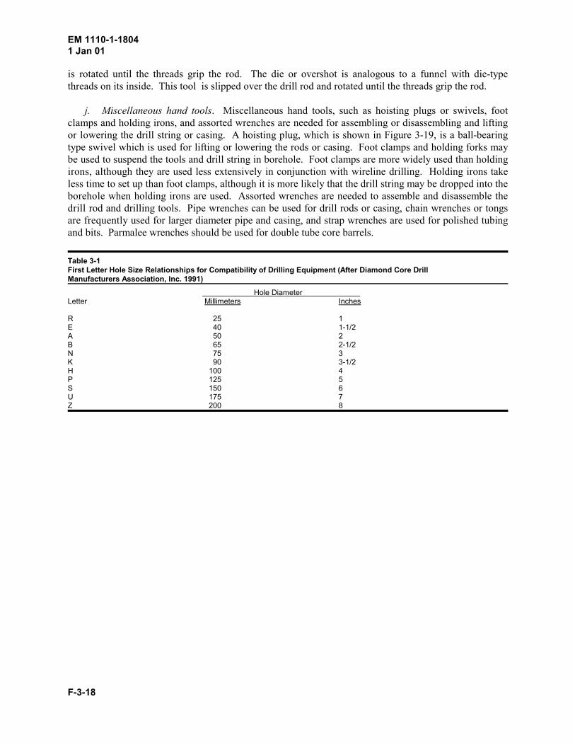
depth with minimum reduction of the core diameter. In other words, NX core-barrel bits will passthrough flush coupled NX casing and will drill a hole large enough to admit flush coupled BX casing,etc. The third letter, i.e., �G,� �M,� or �T,� is the design letter which specifies a standard design, such asthread characteristics. This feature allows for interchangeability of equipment from different manu-facturers. Table 3-1 presents a letter size designation with an approximate borehole dimension for drillrods to be used together with casing, core barrels, diamond bits, and reaming shells. Table 3-2 presentsnominal dimensions for drill rods, core barrels, bits, casings, and accessories.
b. Drill rods. The principal functions of the drill rods are to transmit the downward thrust andtorque from the drill rig to the drill bit and to act as an hydraulic tube for the drilling fluid.Unfortunately, there is very little guidance on the design of drill rods in the DCDMA standards. All thatis specified is that the rods must be designed to provide a sufficiently strong torque tube between the drillrig and the drill bit. The drill rod which must also function as a tube to convey the drilling fluid betweenthe drill rig and the drill bit must have a sufficient wall thickness to accept the threads of adjacent rods orequipment and minimize the cross-sectional area to eliminate weight and reduce cost.
To satisfy these requirements, drill rods are frequently designed as upset tubing rather than as parallelwall tubing. Figure 3-11 illustrates upset and parallel wall tubing. The use of upset rods providessufficient material to accept full threads and thus eliminates unnecessary wall thickness and weight forthe drill rods. Most manufacturers also supply cotton rod wicking for the joints of drill rods. Thewicking improves the hydraulic seal at the joints and tends to increase the ease of �breaking� oruncoupling the drill string. Another common design feature is left-hand threaded drill rods. Left-handthreaded drill rods are useful with fishing tools for �backing off� drill pipe on equipment lost in theborehole.
N- and NW-size (60-mm (2-3/8-in.) and 67-mm (2-5/8-in.) OD, respectively) drill rods are satisfactoryfor common soil drilling and sampling operations. Smaller diameter rods are more flexible and cannotwithstand large torques, whereas larger diameter drill rods are stiffer and capable of withstanding highertorques but are much heavier. For example, the weight of the N- and NW-size drill rods are 76 and 80Newtons per meter (N/m) (5.2 and 5.5 lb/ft), respectively, whereas the weight of the HW-size drill rod is112 N/m (7.7 lb/ft).
c. Drill bits. A variety of bits are available for drilling and sampling operations. The selection ofthe bit is usually dependent on the formation which is to be drilled and the purpose of the borehole, i.e., aborehole for construction purposes, water well, or obtaining samples as a part of a geotechnical siteinvestigation. The types of bits include those for chopping and percussion drilling in soils and soft rocksand those for rotary drilling in soils and rocks. Drill bits may be made of hardened metal, carbide alloy,or diamond. The material used to construct the bit is related to the intended use for the bit. For example,diamond bits are used for drilling hard, intact formations, whereas carbide-tipped sawtooth bits may beused for drilling softer, fractured formations. A discussion of the use of drill bits in various types of geo-logic formations for different purposes is presented in the paragraphs which follow.
(1) Bits for chopping. A chopping bit is a steel bit which is equipped with a hardened cutting edge.The shape of the bit which is available in common sizes depends on the material to be penetrated. Achisel-shaped bit can be used in sands, silts, clays, and soft rocks for advancing the borehole or forcleaning casing. The star- or cross-shaped chopping bit can be used for drilling and fragmenting coarsegravel, boulders, and rock. They are equipped with upward or downward pointing ports for discharge ofthe drilling fluid. When used in conjunction with sampling operations, the upward pointing jet is desir-able because it causes less disturbance to the underlying material. When used in conjunction with wash
EM 1110-1-18041 Jan 01
F-3-12
borings, the downward pointing jet is more desirable because the water jet is helpful in eroding theunderlying material and suspending the cuttings in a slurry. Heavy percussion drill bits are shaped with abeveled edge for breaking the formation. Several chopping bits are shown in Figure 3-12.
(2) Bits for rotary drilling. Both noncoring bits and coring bits may be used in conjunction withrotary drilling operations. Noncoring bits advance the borehole by scraping and shearing chips ofmaterial from the intact formation. These rotary drill bits include drag bits, roller bits, and diamond plugbits. Coring bits, in most cases, are merely a modification of a noncoring bit. The principal differencebetween the noncoring and coring bits is that an annular hole is cut around an intact core by the coringbit. A photograph of several rotary bits is presented as Figure 3-13.
(a) Non-coring bits.
(i) Drag bits. Drag bits, such as fishtail bits, bladed bits, replaceable blade bits, and carbide insertbits, can be used for drilling soils and soft rock. A photograph of several drag bits is presented as Figure3-14. The term �fishtail� was originated by Hvorslev (1949). The fishtail bit resembles a straightchopping bit with a split cutting edge. Each half of the chisel-shaped cutting edge is turned slightly inthe direction of rotation of the blade. A variation of the fishtail bit is the bladed bit. This type of bit mayhave two, three, or four blades or wings which have been turned slightly in the direction of rotation. Thetips of fishtail and bladed bits are usually made of a tungsten carbide alloy for wear resistance.Replaceable blade bits have insert blades which are individually replaceable. The blades are usuallymade of a tungsten carbide alloy or hardened metal. Jets are directed at each of the blades for cleaning.An example of a replaceable blade bit is the Hawthorne bit. Carbide insert bits are similar to bladed bitsexcept the edges are not turned. For these bits, an insert is used to form the cutting edge. Carbide insertbits are available with three or four wings. All bits have large passageways for the drilling fluid.
Drag bits can be used for general drilling operations in most soils and softer rocks. Fishtail and bladedbits can be used for cleaning casing, starting holes, or drilling in sands and clays. The fishtail bit may beequipped with baffles to divert the drilling fluid upward or downward. With upward diverted drillingfluid, the fishtail bit is quite suitable for drilling to the top of the soil to be sampled. Finger-type dragbits can be used for general drilling purposes and are satisfactory for advancing boreholes in soils inwhich a slight disturbance below the bit caused by the jetting action of the drilling fluid is permissible.The configuration of this type of bit makes it impractical to divert the drilling fluid away from the bottomof the hole. Finger-type drag bits are frequently used as the cutting bit for helical augers. However,drilling fluid is not used when auger drilling is conducted. Three- or four-bladed bits are used for drillingin firmer soils, such as hardpan and soft rock.
(ii) Cone and roller bits. Cone bits and roller bits are used for drilling materials containing rocklenses, large gravel, and rock formations. Cone-type bits are designed with two or three cones.Roller-type bits consist of two rollers on a horizontal axes and two rollers on an inclined axis; thehorizontal rollers are mounted perpendicular to the inclined rollers. These bits have teeth milled on thesurfaces of the cones and rollers which rotate as the bit is turned. The spacing and height of teeth isvaried for the type of material to be drilled. For softer materials, larger and fewer teeth are used, whereasshorter and more closely spaced teeth are used for drilling harder materials. The teeth are interfaced sothey become self-cleaning. Air, mud, or water can be used as the drilling fluid and is discharged at thebottom of the bit. Photographs of typical tri-cone bits are presented in Figure 3-15.
To be used efficiently and effectively, a large downward pressure must be applied to the drill bit.Unfortunately, large downward pressures cannot be supplied by conventional drilling rigs. Nevertheless,
EM 1110-1-18041 Jan 01
F-3-13
roller bits are used for many geotechnical investigations, especially when harder materials areencountered. In general, the two-cone bit is used for medium soft formations, fractured rock, andcleaning out casing. The three-cone or tricone bits are used for harder rock. Tricone bits providesmoother operation and are more efficient than the two-cone bit. Of these bits, the tricone bit is mostfrequently used. The costs of tricone bits are greater than the costs of drag bits, although the costs can beoffset by a more rapid rate of advancement of the borehole. The principal disadvantage of tricone bits isthat these bits cannot be used with great success in materials which contain a large percent of gravel.
(iii) Diamond plug bits. Diamond plug bits are noncoring bits which are used in rock formations.The shape of the diamond plug bit is concave, pilot, or taper. The concave bit is least expensive andideal for drilling in soft rock. The pilot bit has a lead section of smaller diameter and is ideal for drillinghard rock and vertical holes in rock of varying hardness. The point tends to minimize vibrations and holedeviations which allow straight, deep holes to be drilled. The taper-type bit is used for drilling very hardrock and for reaming undersized holes. The shape of the taper bit also tends to minimize vibrations andhole deviations.
(b) Coring bits. Coring bits are used for cutting an annular hole around a pedestal of soil or rock tobe sampled. Coring bits include diamond bits, carbide insert bits, and sawtooth bits. The selection of abit is usually based upon the formation or material to be drilled, the cost or availability of various drillbits, and the rate of advancement of the borehole using a particular bit. For example, the cost of adiamond bit for drilling a very hard formation may be offset by a more rapid rate of advancing theborehole. A carbide may be selected for drilling a severely fractured formation; the cost of a damagedcarbide bit would be substantially less than the cost of a damaged diamond bit. Diamond bits include the�hand- set� or �surface-set� diamond type and the �diamond- impregnated� type. Hand-set diamond bitsare used for drilling very hard, intact materials, whereas diamond impregnate bits are used for drillingmore abrasive or fractured materials which would tend to dislodge the diamonds on a hand-set bit.Carbide insert bits can be substituted for diamond bits for most soft to medium-hard drilling operations.Sawtooth bits can be used for soft, fractured, or friable materials.
(i) Diamond bits. The selection of a diamond bit should be based upon the experience of the drillerand/or the guidance of the manufacturer. When a diamond bit is selected, variables such as the qualityand size of the diamonds and the design of the bit, including the face or crown shape, the characteristicsof the bit matrix, the number of waterways, the diamond pattern, etc., should be considered. Thedescription of the bit should specify the core barrel size, the core barrel group, design of the core barrel,the grade and size of the diamonds, the type of matrix, and the number of waterways. The descriptionshould also indicate whether the diamonds in the drill bit are impregnated or hand set. Additional detailsof diamond bits can be obtained from the U. S. Army Corps of Engineers (1959), Southwestern DivisionLaboratory, in a publication entitled �Program for Central Procurement of Diamond Drilling Tools� asdirected by Guide Specification CE-1205 and ER 715-1-13. A photograph of a typical diamond coringbit is presented in Figure 3-16.
(ii) Carbide bits. Carbide bits can be used in much the same manner and for the same purposes asdiamond bits. Two types of carbide bits are available. Standard carbide bits use carbide inserts whichare mounted on the cutting edge of the drill bit. Because of the coarseness of the inserts, very largestresses may be exerted on the formation which would tend to disturb or fracture the formation ahead ofthe bit. Pyramid carbide bits are less likely to chip when subjected to a sharp blow. These bits aresuggested for drilling fractured formations. A photograph of a standard carbide insert bit and a pyramidcarbide bit is presented in Figure 3-17. In general, carbide bits are less expensive than diamond bits.They have no salvage value and therefore are used to destruction. Since carbide bits are not as hard as
EM 1110-1-18041 Jan 01
F-3-14
diamonds, they are limited to drilling softer formations or must be used with a slower rate of advance.Frequently, the slower rate of drilling may offset the higher cost of the diamond bit.
(iii) Sawtooth bits. A photograph of a sawtooth coring bit is presented in Figure 3-18. This bit isequipped with coarse, hard steel teeth which provide tough cutting surfaces that can withstand a greatdeal of shock. The sawtooth bit has a high clearance and can be used for drilling hard soil or soft rockprovided that a good supply of water is available to remove the cuttings. Abrasion of the steel teethlimits the use of this bit to relatively soft formations. The sawtooth bit is fairly inexpensive.
(c) Casing bits and casing shoe bits. The principal differences between casing bits and casing shoebits are the design. Casing bits have cutting edges on the inner and outer surfaces of the bit. Thereduced inside diameter of the casing bit caused by the addition of a cutting surface will not allow thepassage of a standard coring bit of the same size or letter. As this characteristic or feature implies, thecasing and casing bit must be removed and the casing reset before drilling and sampling through thecasing can be conducted. Casing shoe bits are used when drilling through the casing is planned. Acutting surface is not provided on the inside of the bit.
d. Casing. Drill casing can be used to stabilize and prevent caving of material into the borehole.Whenever temporary casing is required, a tube with flush inside and outside joints is advantageous and isusually quite simple and economical to make. A metal tube, such as a thick-walled steel pipe, can be cutwith a taper on the diameter of about 3 cm/m (3/8 in./ft) and machined with coarse square threads; thisdesign provides a strong flush joint that makes and breaks easily.
Two DCDMA standard series of casing are available. The �X� casing is flush coupled tubing with finethreads. The casing is equipped with box threads at each end; the coupling is equipped with pin threadsat each end. The �W� casing is designed with a flush joint and uses coarse threads. It is machined with apin thread on one end and a box thread on the other end. The principal advantage of the �X� casing isthat it is lighter weight than the �W� casing. However, the �W� casing is thicker walled and is morerobust than the �X� casing.
Casing can be advanced by driving or �drilling� it to the desired depth. If the casing is driven, thedriving hammer, a driving shoe, a driving guide, and an assembly to pull the casing are needed. Drillingthe casing into the ground requires the use of a casing shoe or a carbide, sawtooth, or diamond casing bit,depending on the geologic conditions. In addition to the casing and shoe or bit, a water circulationsystem is also needed to remove material from the casing. It is preferable that the drill is equipped with ahydraulic pulldown drive and has a drill head and spindle which is large enough to pass the casingthrough the drill head. If the casing will not fit through the drill head, a drill rod and sub can be attachedto the casing; this method is tedious because short lengths of casing must be used. Additionalinformation on the placement of casing is presented in paragraphs 6-2b and 8-1b.
e. Portable sumps. For rotary drilling operations in which drilling mud or clear water is used, mudpits are needed for capturing the drilling fluid as it is returned from the borehole. The mud pit must alsofunction as a settling pit for the cuttings which are suspended in the drilling fluid. Either portable sumpsor dug pits can be used for these purposes. See paragraph 4-4 for a discussion of the requirements of themud pit. Generally, portable sumps are more convenient and economical than dug pits.
f. Surface casing. The function of the surface casing is to minimize the erosion caused by thedrilling fluid and to prevent the borehole from �cratering� at the surface. A suitable collar is a short
EM 1110-1-18041 Jan 01
F-3-15
section of casing, i.e., 0.6 or 1.5 m (2 or 5 ft), which can be driven or spun into the ground before thedrilling has commenced.
g. Augers. Augers are used primarily for general exploration, advancing and cleaning the borehole,and drilling accessible borings. Augers are also used for various construction operations, such as drillingdrainage wells and excavating for piers and caissons. Disturbed or undisturbed samples can be obtainedfrom boreholes advanced by augering methods. However, disturbed samples may not be representativeof the in situ deposit because materials may have segregated during the augering process or may havebeen contaminated with soils from different depths. The quality of undisturbed samples may also bequestionable as a result of stress relief, especially if drilling mud is not used to stabilize the borehole.Augers cannot be used for soils in which the gravel particles or rock fragments are greater than approx-imately one-tenth of the diameter of the hole.
(1) Hand-held augers. Hand-held augers include the Iwan auger, which is commonly referred to as aposthole digger, and small helical augers, such as the ship auger and open spiral or closed spiral augers.The Iwan auger ranges in diameter from 8 to 20 cm (3 to 8 in.) and can be used in stable cohesive orcohesionless soils above the water table. The ship auger is most effective in cohesive materials. Itranges in diameter from 5 to 9 cm (2 to 3-1/2 in.). Open- and closed-spiral augers were developed forsoils in which poor recovery was obtained using the ship auger. These augers generally work well in dryclays and gravelly soils. Open- and closed-spiral augers are available with an outside diameter of 5 cm(2 in.). A photograph of Iwan-type posthole augers is presented in Figure 7-1.
The hand-held auger consists of an auger blade attached to one end of a pipe and a crossarm attached tothe other end of the pipe. A 2-cm- (3/4-in.-) diam pipe is commonly used although a larger diameter pipecan be used for deep holes. Extensions can be added to the pipe as needed. The maximum depth whichcan be probed with the handheld auger is about 9 to 10 m (30 to 33 ft). To sample, the auger is rotated asdownward pressure is applied. When the blades are full, the auger is withdrawn from the borehole anddumped. For most soils, the sample is satisfactory for identification and classification tests.
(2) Power augers. The principal differences between power-driven augers and hand-held augers arethe rigidity and robustness of the power equipment and the size and depth of samples which can beobtained. For example, barrel and bucket augers are a modification of the Iwan-type auger. Disk augersand solid- and hollow-stem flight augers are helical augers. Spoon augers are similar to closed-spiralaugers. The diameter of power augers ranges from approximately 5 to 244 cm (2 to 96 in.). The depth ofsamples obtained with power equipment can exceed 30 m (100 ft) or more, depending upon thegroundwater conditions and the type of equipment which is used. Barrel, bucket, and flight augers arediscussed in Chapters 5 through 8 of this manual.
In general, power augers can be used wherever the borehole is stable and will remain open. The principaldisadvantage of sampling by auger methods is that samples are highly disturbed and soils from differentstrata can be mixed. Because of the potential for mixing of soils from different strata, stratigraphiclogging using cuttings from auger borings is extremely difficult. An exception exists, however. When ahollow-stem auger is used, the center plug can be removed at any time and either disturbed or undis-turbed samples can be obtained with conventional sampling equipment. Large bucket augers can also beused for drilling large-diameter boreholes which will permit a man to enter and obtain hand-carvedsamples. The limiting depth for power augering is usually controlled by the power which is required torotate the auger or the depth to the groundwater table. For continuous flight augers and bucket augers,the limiting depth is about 30 m (100 ft). For short-flight augers, the depth is limited to the length of thekelly on the drill rig, which is about 3 to 6 m (10 to 20 ft), depending on the particular device.
EM 1110-1-18041 Jan 01
F-3-16
(a) Bucket augers. The bucket auger is an open top metal cylinder with one or more slots in itsbottom which permit soil to enter as the bucket is rotated and downward pressure is applied. The slotsare reinforced and are usually equipped with teeth or a cutting edge. To operate, the bucket auger isattached to the kelly rod. It is driven by a rotary table. Rotation and downward pressure are used to fillbucket. When the bucket is full, the rotation is stopped and the bucket is lifted from the borehole. Whenthe bucket is clear of the borehole, it can be emptied by tipping. Some buckets, such as the Vicksburghinged auger which is shown in Figure 7-2, are equipped with hinges and a trip release which allow thebucket to be opened for dumping. The principal advantage of the bucket auger is the rapid excavation ofsmall- or large-diameter holes to relatively great depths. The principal disadvantage is that most bucketaugers cannot be used for drilling cohesionless materials below the water table or to sample gravellysoils.
(b) Flight augers. The flight auger is the most commonly used power auger. It consists of one ofmore flights of helical or spiral fluting attached to a torque bar. Hence, the respective auger is called�single-flight� or �continuous-flight.� Likewise, the torque bar may be solid or hollow, which explainsthe terms �solid-stem� or �hollow-stem.� One end of the torque bar is connected to the drill, and theother end can be fitted with a pilot bit and cutting teeth or some other type of bit for ripping the materialto be drilled. The spiral fluting acts as a platform for removal of cuttings to the surface.
The diameters of solid-stem flight augers range from 57 mm (2-1/4 in.) to 1.2 m (48 in.), or larger,although flight augers with diameters to 30 cm (12 in.) are the most common. A table of common sizesof flight augers is presented in Chapter 5. The principal advantage of solid-stem flight augers is that aminimum number of tools is required to advance the borehole. These augers can be used for drilling instable soils, including gravel and soft rock. They do not work well for drilling in hard cementedmaterials. Solid-stem flight augers cannot be used for drilling cohesionless materials below the watertable because the material tends to wash off the auger flights and the holes generally will not remainopen.
The hollow-stem auger consists of a section of seamless tube which is wrapped with spiral flight. It isfitted with an adapter cap at its top and a center plug and cutter head at its lower end. The cutter head isconnected to the drill rig by drill rods which attach to the adapter at the top of the auger. The cutter headmay be equipped with finger-type bits for general drilling, fishtail bits for drilling cohesive materials, orcarbide teeth for drilling in hard or stiff deposits. The adapter cap is designed to hold the center plug inplace as the auger is advanced. It ensures that the center stem and bit rotate with the auger. Whendrilling and sampling with the hollow-stem auger, the hole is usually advanced with the center plug andstem in place, although the center plug may be omitted for certain soils. The hollow-stem flights andcenter stem can be added as necessary. At the desired sampling depth, the center stem and plug can beremoved and sampling may be conducted through the hollow stem of the auger. The hollow stem servesas casing.
Two types of connectors are used to connect stems of continuous-flight augers. Screwed joints are easyto connect and form a watertight, rigid, stiff connection. The disadvantages are that the auger cannot beoperated in reverse and the stems may be difficult to disconnect, especially if soil particles becomewedged in the threads or the threads become worn or damaged. Splined joints transfer torque betweenauger stems by an octagonal socket and shank jaw coupling or a straight keyed coupling. Tension istransferred by a removable threaded set screw or pin. Splined joints are fairly easy to connect anddisconnect, although they may be somewhat difficult to align during assembly. They can also transfer areverse torque between the auger stems. The principal disadvantages are that the joints are not watertightand must be cleaned regularly before assembly. If O-ring seals are used to effect a watertight seal, the
EM 1110-1-18041 Jan 01
F-3-17
O-rings must be replaced frequently because of wear. The hollow-stem auger can be used in loosecohesionless deposits below the groundwater table. The ID of hollow-stem augers ranges from about 7 to30 cm (2-3/4 to 12 in.). The principal advantage of hollow-stem, continuous-flight augers is that theauger serves as a casing for sampling soft or unstable soils. Furthermore, it is likely that less disturbanceto the formation is caused by augering than by driving casing. The principal disadvantage of thehollow-stem auger is the cost and size of the equipment which is required to operate the auger. Smalltools which are needed for handling auger stems include the auger holding fork shown in Figure 3-19.
h. Bailers and sand pumps. Bailers and sand pumps are used for removing material from boreholes,especially in conjunction with churn and percussion drilling operations. Bailers are fairly easy to operateand are satisfactory for bailing water and soft materials from below the water table in cased boreholes ifagitation in the bottom of the borehole is permissible. Where agitation must be minimized, a sand pumpshould be used. Unfortunately, the cost of a sand pump is greater than the cost of a bailer. The diameterof the borehole made by either of these devices is approximately 2.5 to 5.0 cm (1 to 2 in.) greater than thediameter of the apparatus.
(1) Sand pump. A sand pump consists of a tube equipped with a plunger or piston located inside thetube. The bottom of the tube is equipped with a flap or valve for retaining material in the pump. Thebottom of the tube may also be equipped with a sawtooth bit, especially if the material must be brokenprior to its removal from the borehole. To operate, the plunger is moved up and down to create a suction.The suction causes the slurry and cuttings at the bottom of the borehole to flow into the tube throughopenings in the sidewall and the bottom. To empty the cuttings from the tube, the plunger is removedand the pump is inverted or the valve must be removed.
(2) Bailer. A bailer consists of a pipe with a valve at its lower end and a bail at its upper end. Thebail is used to provide a connection for the cable line on the rig which is used to operate the bailer. Avalve is needed to retain the material in bailer as it is lifted to surface. Two types of bailers are available.
(a) Flat valve bailer. The flat valve bailer is equipped with a flat valve which opens to receivematerial as the bailer is lowered and closes as the bailer is lifted. To operate, the device is lowered to thebottom of the borehole and then is moved up and down a few inches to create a pumping action. Whenthe bailer is full, it is removed from the borehole and must be turned upside down to empty.
(b) Dart valve bailer. The dart valve bailer is equipped with a valve which is shaped like a dart.One end of the valve is a flat plate and the other end is shaped like a cone. To operate, the bailer isdropped to the bottom of the borehole. When the dart strikes the bottom of the boring, the flat plate liftsthe cone-shaped valve from its seat and allows slurry to enter the bailer. When the bailer is lifted, thecone-shaped valve drops into its seat to retain the material. To empty the bailer, the dart is touched onthe ground which opens the valve. If valve becomes stuck, the bailer can be turned upside down to emptythe material.
i. Fishing tools. Whenever a string of drill rods or a drill bit is lost in a borehole, such as when thedrill string is dropped or the bit is sheared from the drill rod, tools are used to recover this equipmentfrom the borehole, if possible. A special device, called a fishing tool, is attached to the bottom of asection of drill rod and is lowered to the elevation of the top of the lost equipment. The drill rod is thenraised and lowered and hopefully can be used to make contact with the lost equipment.
Two types of fishing tools are available: a spear or tap and a die or overshot. The spear is a long,slender pointed tool with tap threads on its periphery. When the spear has been seated in the drill rod, it
EM 1110-1-18041 Jan 01
F-3-18
is rotated until the threads grip the rod. The die or overshot is analogous to a funnel with die-typethreads on its inside. This tool is slipped over the drill rod and rotated until the threads grip the rod.
j. Miscellaneous hand tools. Miscellaneous hand tools, such as hoisting plugs or swivels, footclamps and holding irons, and assorted wrenches are needed for assembling or disassembling and liftingor lowering the drill string or casing. A hoisting plug, which is shown in Figure 3-19, is a ball-bearingtype swivel which is used for lifting or lowering the rods or casing. Foot clamps and holding forks maybe used to suspend the tools and drill string in borehole. Foot clamps are more widely used than holdingirons, although they are used less extensively in conjunction with wireline drilling. Holding irons takeless time to set up than foot clamps, although it is more likely that the drill string may be dropped into theborehole when holding irons are used. Assorted wrenches are needed to assemble and disassemble thedrill rod and drilling tools. Pipe wrenches can be used for drill rods or casing, chain wrenches or tongsare frequently used for larger diameter pipe and casing, and strap wrenches are used for polished tubingand bits. Parmalee wrenches should be used for double tube core barrels.
Table 3-1First Letter Hole Size Relationships for Compatibility of Drilling Equipment (After Diamond Core Drill Manufacturers Association, Inc. 1991)
Hole Diameter Letter Millimeters Inches
R 25 1E 40 1-1/2A 50 2B 65 2-1/2N 75 3K 90 3-1/2H 100 4P 125 5S 150 6U 175 7Z 200 8

EM 1110-1-1804
1 Jan 01
F-3-19
Table 3-2Nominal Dimensions for Casing and Accessories (after Diamond Core Drill Manufacturers Association, Inc. 1991) (Continued)
Rod Flush Coupled Flush Joint Casing Core Core Core Drill Rod Coupling Casing Coupling Casing Casing Bit Shoe Bit Bit Barrel Diameter1 1
Size O.D. I.D. I.D. O.D. I.D. I.D. O.D. I.D. O.D. I.D. O.D. I.D. O.D. O.D. O.D.Designation mm mm mm mm mm mm mm mm mm mm mm mm mm mm mm E 33.3 22.2 11.1 ----- ----- ----- ----- ----- ----- ----- ----- ----- ----- ----- -----2,3
A 41.3 28.6 14.3 ----- ----- ----- ----- ----- ----- ----- ----- ----- ----- ----- -----2,3
B 47.6 31.7 15.9 ----- ----- ----- ----- ----- ----- ----- ----- ----- ----- ----- -----2,3
N 60.3 50.8 25.4 ----- ----- ----- ----- ----- ----- ----- ----- ----- ----- ----- -----2,4
RX ----- ----- ----- 36.5 30.2 30.5 ----- ----- 37.7 25.4 37.7 30.1 ----- ----- -----EX ----- ----- ----- 46.0 41.3 38.1 ----- ----- 47.6 35.7 47.6 38.0 ----- ----- -----AX ----- ----- ----- 57.2 50.8 48.4 ----- ----- 59.6 45.2 59.6 48.3 ----- ----- -----BX ----- ----- ----- 73.0 65.1 60.3 ----- ----- 75.3 56.3 75.3 60.2 ----- ----- -----NX ----- ----- ----- 88.9 81.0 76.2 ----- ----- 91.8 72.1 91.8 76.0 ----- ----- -----HX ----- ----- ----- 114.3 104.8 100.0 ----- ----- 117.4 95.9 117.5 99.7 ----- ----- -----RW 27.8 18.3 10.3 ----- ----- ----- 36.5 30.5 37.7 25.4 37.7 30.1 ----- ----- -----3
EW 34.9 25.4 11.1 ----- ----- ----- 46.0 38.1 47.6 35.7 47.6 38.0 ----- ----- -----3
AW 44.5 34.9 15.9 ----- ----- ----- 57.2 48.4 59.6 45.2 59.6 48.3 ----- ----- -----3
BW 54.0 44.5 19.1 ----- ----- ----- 73.0 60.3 75.3 56.3 75.3 60.2 ----- ----- -----4
NW 66.7 57.2 34.9 ----- ----- ----- 88.9 76.2 91.8 72.1 91.8 76.0 ----- ----- -----4
HW 88.9 77.8 60.3 ----- ----- ----- 114.3 100.0 117.5 96.0 117.5 101.0 ----- ----- -----4
PW ----- ----- ----- ----- ----- ----- 139.7 127.0 143.5 117.7 143.5 123.2 ----- ----- -----SW ----- ----- ----- ----- ----- ----- 168.3 152.4 172.5 143.1 172.5 150.8 ----- ----- -----UW ----- ----- ----- ----- ----- ----- 193.7 177.8 198.1 171.6 198.1 175.4 ----- ----- -----ZW ----- ----- ----- ----- ----- ----- 219.1 203.2 223.9 197.0 223.9 202.6 ----- ----- -----EWG ----- ----- ----- ----- ----- ----- ----- ----- ----- ----- ----- ----- 37.3 36.5 21.4AWG ----- ----- ----- ----- ----- ----- ----- ----- ----- ----- ----- ----- 47.6 46.0 30.0BWG ----- ----- ----- ----- ----- ----- ----- ----- ----- ----- ----- ----- 59.5 57.9 42.0NWG ----- ----- ----- ----- ----- ----- ----- ----- ----- ----- ----- ----- 75.3 73.8 54.7HWG ----- ----- ----- ----- ----- ----- ----- ----- ----- ----- ----- ----- 98.8 95.2 76.2EWM ----- ----- ----- ----- ----- ----- ----- ----- ----- ----- ----- ----- 37.3 36.5 21.4AWM ----- ----- ----- ----- ----- ----- ----- ----- ----- ----- ----- ----- 47.6 46.0 30.0BWM ----- ----- ----- ----- ----- ----- ----- ----- ----- ----- ----- ----- 59.5 57.9 42.0NWM ----- ----- ----- ----- ----- ----- ----- ----- ----- ----- ----- ----- 75.3 73.8 54.7RWT ----- ----- ----- ----- ----- ----- ----- ----- ----- ----- ----- ----- 29.4 28.5 18.6EWT ----- ----- ----- ----- ----- ----- ----- ----- ----- ----- ----- ----- 37.3 36.5 22.9AWT ----- ----- ----- ----- ----- ----- ----- ----- ----- ----- ----- ----- 47.6 46.8 32.5BWT ----- ----- ----- ----- ----- ----- ----- ----- ----- ----- ----- ----- 59.5 58.7 44.4NWT ----- ----- ----- ----- ----- ----- ----- ----- ----- ----- ----- ----- 75.3 73.8 58.7HWT ----- ----- ----- ----- ----- ----- ----- ----- ----- ----- ----- ----- 98.8 96.8 80.92-3/4 X 3-7/8 ----- ----- ----- ----- ----- ----- ----- ----- ----- ----- ----- ----- 97.5 92.0 68.35
4 × 5-1/2 ----- ----- ----- ----- ----- ----- ----- ----- ----- ----- ----- ----- 138.0 133.3 100.85
6 × 7-3/4 ----- ----- ----- ----- ----- ----- ----- ----- ----- ----- ----- ----- 194.4 184.1 151.65
AQ 44.5 34.9 ----- ----- ----- ----- ----- ----- ----- ----- ----- ----- ----- 48.0 27.06
BQ 55.6 46.0 ----- ----- ----- ----- ----- ----- ----- ----- ----- ----- ----- 60.0 36.56
NQ 69.9 60.3 ----- ----- ----- ----- ----- ----- ----- ----- ----- ----- ----- 75.7 47.66
HQ 88.9 77.8 ----- ----- ----- ----- ----- ----- ----- ----- ----- ----- ----- 96.0 63.56
For casing, the minimum physical strength characteristics are 450 MPa (65,000 psi) yield stress and 550 MPa (80,000 psi) tensile stress.1
Old standard, but still in use on some projects.2
Parallel wall rod. The minimum physical strength characteristics are 450 MPa (65,000 psi) yield stress and 550 MPa (80,000 psi) tensile stress.3
Upset end drill rod. The minimum physical strength characteristics are 275 MPa (40,000 psi) yield stress and 415 MPa (60,000 psi) tensile stress.4
Large design core barrels; 69.9 mm by 98.4 mm, 101.6 mm by 139.7 mm, 152.4 mm by 196.9 mm, respectively.5
Wire line size designation (after Longyear 1981). Drill rod serves as casing and drill rod. Core bits and core diameters vary slightly according to the manufacturer.6
EM 1110-1-18041 Jan 01
F-3-20
Figure 3-1. Truck-mounted rotary drill rig with a hydraulic drive system
EM 1110-1-18041 Jan 01
F-3-21
Figure 3-2. Photograph of a truck-mounted rotary drill rig with specific features of the drill rigidentified
EM 1110-1-18041 Jan 01
F-3-22
Figure 3-3. Truck-mounted rotary drill rig with a chain feed drive system
Figure 3-4. Photograph of a Becker hammer drill
EM 1110-1-18041 Jan 01
F-3-23
Figure 3-5. Schematic of Becker hammer drilling and/or sampling operations using reverse air cir-culation (Harder 1993)
EM 1110-1-18041 Jan 01
F-3-24
Figure 3-6. Isometric diagram of the double-wall casing with reverse air circulation for removal ofcuttings (Harder 1993)
EM 1110-1-18041 Jan 01
F-3-25
Figure 3-7. Photograph of several open-type Becker bits (Harder 1993)
Figure 3-8. Photograph of a plugged bit which is used to obtain Beckerpenetration resistance (Harder 1993)
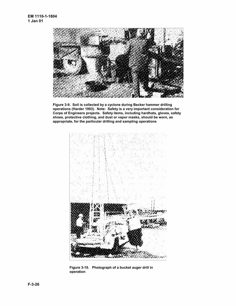
EM 1110-1-18041 Jan 01
F-3-26
Figure 3-9. Soil is collected by a cyclone during Becker hammer drillingoperations (Harder 1993). Note: Safety is a very important consideration forCorps of Engineers projects. Safety items, including hardhats, gloves, safetyshoes, protective clothing, and dust or vapor masks, should be worn, asappropriate, for the particular drilling and sampling operations
Figure 3-10. Photograph of a bucket auger drill inoperation
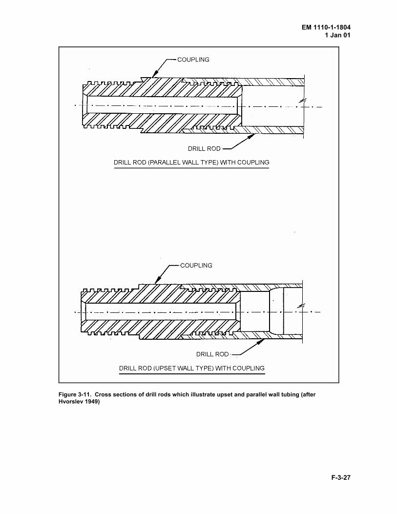
EM 1110-1-18041 Jan 01
F-3-27
Figure 3-11. Cross sections of drill rods which illustrate upset and parallel wall tubing (afterHvorslev 1949)
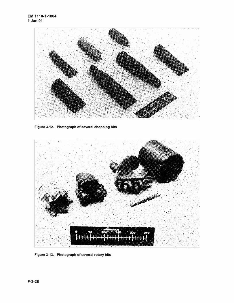
EM 1110-1-18041 Jan 01
F-3-28
Figure 3-12. Photograph of several chopping bits
Figure 3-13. Photograph of several rotary bits
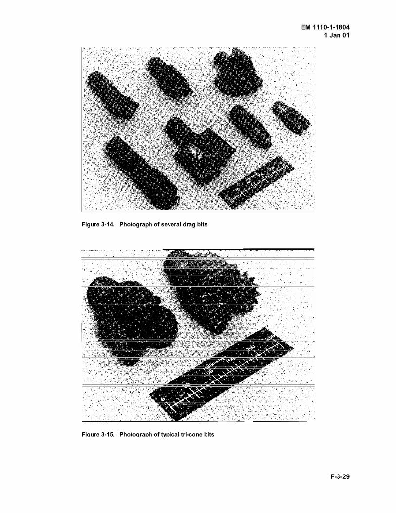
EM 1110-1-18041 Jan 01
F-3-29
Figure 3-14. Photograph of several drag bits
Figure 3-15. Photograph of typical tri-cone bits
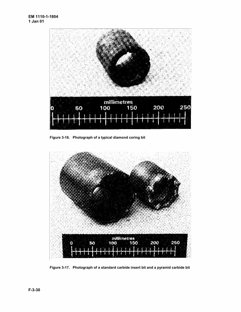
EM 1110-1-18041 Jan 01
F-3-30
Figure 3-16. Photograph of a typical diamond coring bit
Figure 3-17. Photograph of a standard carbide insert bit and a pyramid carbide bit
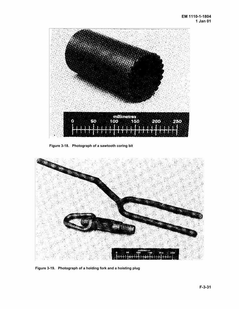
EM 1110-1-18041 Jan 01
F-3-31
Figure 3-18. Photograph of a sawtooth coring bit
Figure 3-19. Photograph of a holding fork and a hoisting plug