Embed Size (px)
Citation preview
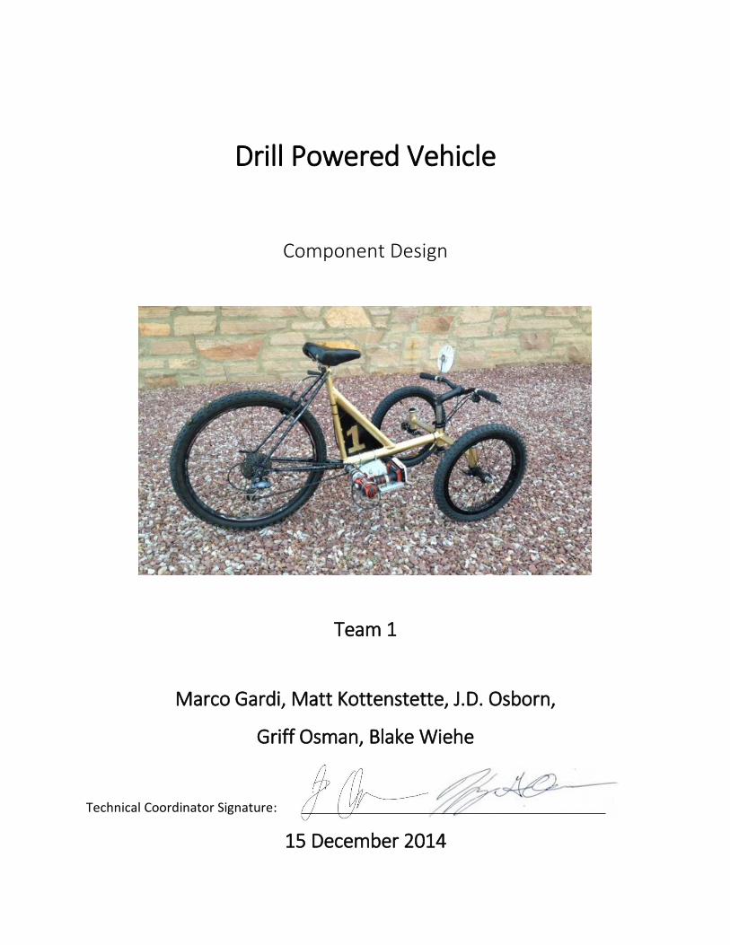
Drill Powered Vehicle
Component Design
Team 1
Marco Gardi, Matt Kottenstette, J.D. Osborn,
Griff Osman, Blake Wiehe
Technical Coordinator Signature:
15 December 2014

Table of Contents
Introduction/Background . . . . . . . . . . . . . . . . . . . . . . . . . . . . . . 1
Vehicle Design . . . . . . . . . . . . . . . . . . . . . . . . . . . . . . . . . . . . . . . 3
Vehicle Analysis . . . . . . . . . . . . . . . . . . . . . . . . . . . . . . . . . . . . . . 7
Fabrication . . . . . . . . . . . . . . . . . . . . . . . . . . . . . . . . . . . . . . . . . . 9
Vehicle Testing and Results. . . . . . . . . . . . . . . . . . . . . . . . . . . . 11
Bill of Materials/Cost. . . . . . . . . . . . . . . . . . . . . . . . . . . . . . . . . . 14
References . . . . . . . . . . . . . . . . . . . . . . . . . . . . . . . . . . . . . . . . . . 15
Appendices . . . . . . . . . . . . . . . . . . . . . . . . . . . . . . . . . . . . . . . . . 16
Table of Figures
Figure 1 – Side View Concept 1 . . . . . . . . . . . . . . . . . . . . . . . . . 3
Figure 2 – Top View Concept 1. . . . . . . . . . . . . . . . . . . . . . . . . . 3
Figure 3 – Top View Steering Concept. . . . . . . . . . . . . . . . . . . . 3
Figure 4 – Front View Steering Concept . . . . . . . . . . . . . . . . . . 3
Figure 5 – Side View Concept 3 . . . . . . . . . . . . . . . . . . . . . . . . . 4
Figure 6 – Top View Concept 3 . . . . . . . . . . . . . . . . . . . . . . . . . .4
Figure 7 – Side/Top View Concept 4 . . . . . . . . . . . . . . . . . . . . . 4
Figure 8 – Front Steer Assembly. . . . . . . . . . . . . . . . . . . . . . . . . 5
Figure 9 – Front Chain Ring Drive Assembly. . . . . . . . . . . . . . . . 5
Figure 10 – Final Vehicle Assembly . . . . . . . . . . . . . . . . . . . . . . . 6
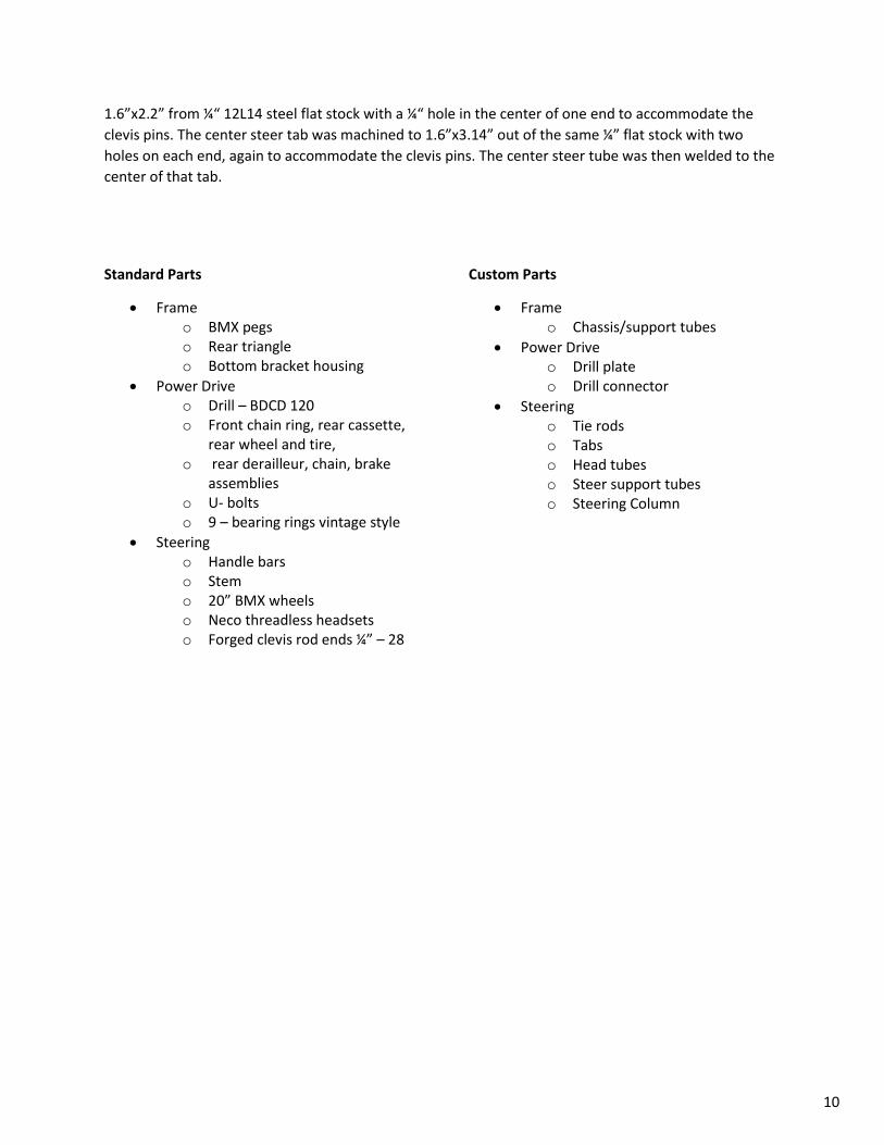
Figure 11 – Original Drill Plate Design . . . . . . . . . . . . . . . . . . . . . 6
Figure 12 – Iterated Drill Plate Design . . . . . . . . . . . . . . . . . . . . . 6
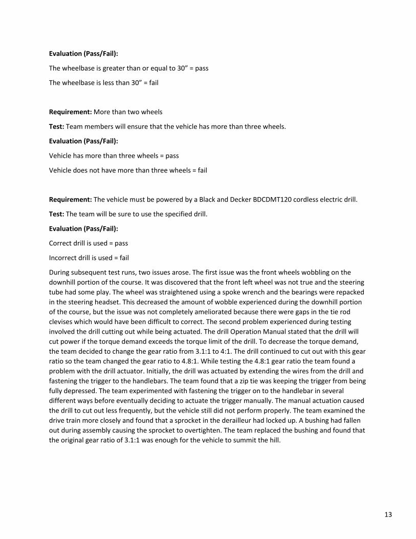
Figure 13 – Original Drill Adaptor Design. . . . . . . . . . . . . . . . . . . 6
Figure 14 – Iterated Drill Adaptor Design. . . . . . . . . . . . . . . . . . . 6
Figure 15 – Force Calculations Diagram . . . . . . . . . . . . . . . . . . . . 7
Table of Tables
Table 1 – Bill of Materials. . . . . . . . . . . . . . . . . . . . . . . . . . . . . . .14
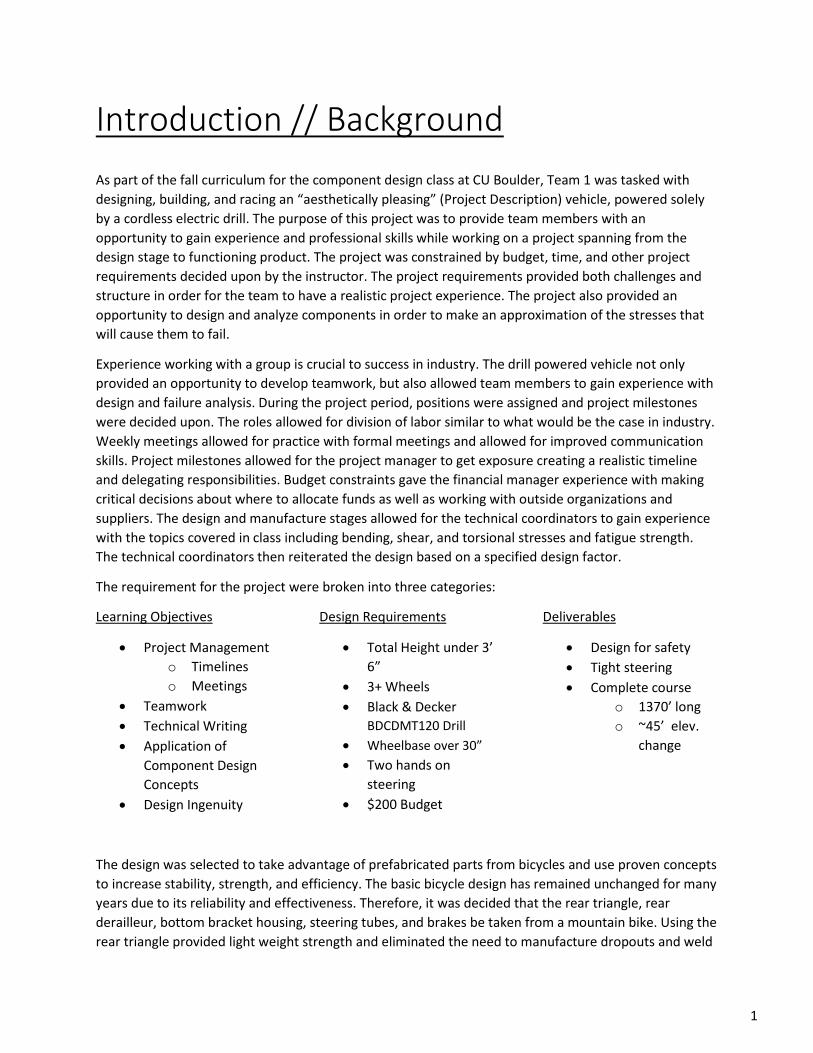
Introduction // Background
As part of the fall curriculum for the component design class at CU Boulder, Team 1 was tasked with
designing, building, and racing an “aesthetically pleasing” (Project Description) vehicle, powered solely
by a cordless electric drill. The purpose of this project was to provide team members with an
opportunity to gain experience and professional skills while working on a project spanning from the
design stage to functioning product. The project was constrained by budget, time, and other project
requirements decided upon by the instructor. The project requirements provided both challenges and
structure in order for the team to have a realistic project experience. The project also provided an
opportunity to design and analyze components in order to make an approximation of the stresses that
will cause them to fail.
Experience working with a group is crucial to success in industry. The drill powered vehicle not only
provided an opportunity to develop teamwork, but also allowed team members to gain experience with
design and failure analysis. During the project period, positions were assigned and project milestones
were decided upon. The roles allowed for division of labor similar to what would be the case in industry.
Weekly meetings allowed for practice with formal meetings and allowed for improved communication
skills. Project milestones allowed for the project manager to get exposure creating a realistic timeline
and delegating responsibilities. Budget constraints gave the financial manager experience with making
critical decisions about where to allocate funds as well as working with outside organizations and
suppliers. The design and manufacture stages allowed for the technical coordinators to gain experience
with the topics covered in class including bending, shear, and torsional stresses and fatigue strength.
The technical coordinators then reiterated the design based on a specified design factor.
The requirement for the project were broken into three categories:
Learning Objectives
Project Management
o Timelines
o Meetings
Teamwork
Technical Writing
Application of
Component Design
Concepts
Design Ingenuity
Design Requirements
Total Height under 3’
6”
3+ Wheels
Black & Decker
BDCDMT120 Drill
Wheelbase over 30”
Two hands on
steering
$200 Budget
Deliverables
Design for safety
Tight steering
Complete course
o 1370’ long
o ~45’ elev.
change
The design was selected to take advantage of prefabricated parts from bicycles and use proven concepts
to increase stability, strength, and efficiency. The basic bicycle design has remained unchanged for many
years due to its reliability and effectiveness. Therefore, it was decided that the rear triangle, rear
derailleur, bottom bracket housing, steering tubes, and brakes be taken from a mountain bike. Using the
rear triangle provided light weight strength and eliminated the need to manufacture dropouts and weld
1

several rods together. The rear derailleur allowed for selective gearing which could improve efficiency
on the varying course grade. Using the bottom bracket housing allowed for use of the bottom bracket
and eliminated the need to buy more bearings and manufacture pillow blocks holders. Using the
steering tubes cut down on cost and allowed for larger downward forces near the front of the vehicle.
All of these components were used in ways similar to what they were designed for which provided the
team with confidence that they would not fail under the applied stresses. The steering design utilized tie
rods to allow for the steering shaft, front left wheel, and front right wheel to each rotate around a
different z-axis. This allowed for the stresses from the weight on the wheels to be distributed across
three sets of bearings rather than one. The tie rod steering system also maintained a constant
wheelbase therefore improving stability. This concept has been proven effective by the automotive
industry. The team chose to have two front steering wheels rather than two rear driving wheels because
having one driving wheel simplified the drive train and having two front steering wheels allowed for
more stability on curving downhill sections.
Altogether, the aspects of the drill powered vehicle project provided a great opportunity for the team to
practice researching existing designs, apply knowledge learned in recent classes, and gain professional
skills which will be essential in an engineering career. The routine mentor meetings, design checks, and
project milestones provided structure and kept the team on track to gain the experience in the most
important areas.
2

Fig. 1 – Side View Concept 1 Fig. 2 – Top View Concept 1
Fig. 3 – Top View Steering Concept Fig. 4 – Front View Steering Concept
Vehicle Design
Conceptual Designs
Initially Team 1 members individually brainstormed conceptual designs. These designs were motivated
by existing designs such as the common bicycle, tricycle, racing wheelchair, wagon, scooter and chariot.
Each team member had a unique design. The team then met and combined the best components from
each design to develop a final design which was decided upon to be the most reasonable design suited
for the needs of the project.
The design in Figures 1 and 2 was loosely based off of a three-wheeled scooter. The rear wheel would be
a bicycle wheel driven by the cordless drill and the front wheels would be used to steer the vehicle. The
issues with this design were the potential stresses in the rear fork and the driver placement.
Figures 3 and 4 depict two ideas for steering mechanisms. Figure 3 was a differential steering system
that used a rigid linkage, while Figure 4 was a steering system that used a chain to change the angle of
the front wheels. The team decided that both of these designs were an improvement over having a
single pivot point. The team further decided that the design using the rigid linkage would be easier to
manufacture and more reliable.
3

Fig. 5 – Side View Concept 3 Fig. 6 – Top View Concept 3
Fig. 7 – Side/Top View Concept 4
Figures 5and 6 show another three-wheeled design with two inverted bike frames welded together to
form the chassis. The issue with this design was the forward facing castor wheels which were likely to
cause instability and possibly inefficiency when driving.
Figure 9 shows a scooter inspired design in which the driver would lie down and steer. The advantage of
this design was the low center of gravity.
The key components that the team decided to use for the final design were the differential steering
using a linkage, the rear driving bike wheel and triangle with derailleur and chain tensioner, three-wheel
design with two wheels in the front, and low center of gravity frame design.
Selected Design
The overall design of the vehicle was selected to take advantage of two beneficial vehicle characteristics
-- stability and selective gearing. From these criteria it was decided that the vehicle should have two
front steering wheels and one rear drive wheel. This design allows for a higher degree of stability while
cornering than would a traditional tri-cycle design. The design also allows for the use of a bicycle drive
train with limited modification required of an existing bicycle.
4

Fig. 9 – Front Chain Ring Drive Assembly
Fig. 8 – Front Steer Assembly
The steering mechanism utilizes a central bicycle handle bar that is connected via tie rods to the two
outboard wheel assemblies. The use of an existing handlebar simplifies mounting the driver controls
(brake levers, gear shifters, etc.) using existing hardware and allows for control of the vehicle using one
or two hands.
The drive train will utilize the existing rear gears and shifting mechanism (derailleur) which will be
connected via a bicycle chain to an 11-tooth front chain ring which is directly driven by the drill. A
fabricated drill adaptor will hold the 11-tooth chain ring and mount into the existing bottom bracket
housing. The drill will be mounted outboard of the frame to the riders right side. The use of the
selective gearing will allow for a 3:1 to a 1:1 gear ratio that can be changed to accommodate changes in
terrain while maintaining an efficient operation of the drill.
All materials used to manufacture the various components of the vehicle will be made from steel. Steel
was selected as the primary material because the bike that was purchased is made from steel. To utilize
and repurpose as much of the bike as possible, welded attachments will have to be made, thus requiring
the use of steel in the manufactured parts.
5
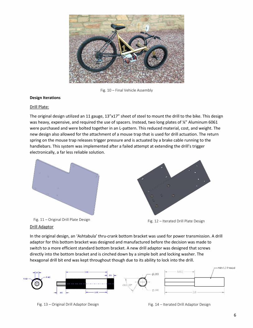
Fig. 12 – Iterated Drill Plate Design
Fig. 13 – Original Drill Adaptor Design Fig. 14 – Iterated Drill Adaptor Design
Fig. 10 – Final Vehicle Assembly
Design Iterations
Drill Plate:
The original design utilized an 11 gauge, 13”x17” sheet of steel to mount the drill to the bike. This design
was heavy, expensive, and required the use of spacers. Instead, two long plates of ¼” Aluminum 6061
were purchased and were bolted together in an L-pattern. This reduced material, cost, and weight. The
new design also allowed for the attachment of a mouse trap that is used for drill actuation. The return
spring on the mouse trap releases trigger pressure and is actuated by a brake cable running to the
handlebars. This system was implemented after a failed attempt at extending the drill’s trigger
electronically, a far less reliable solution.
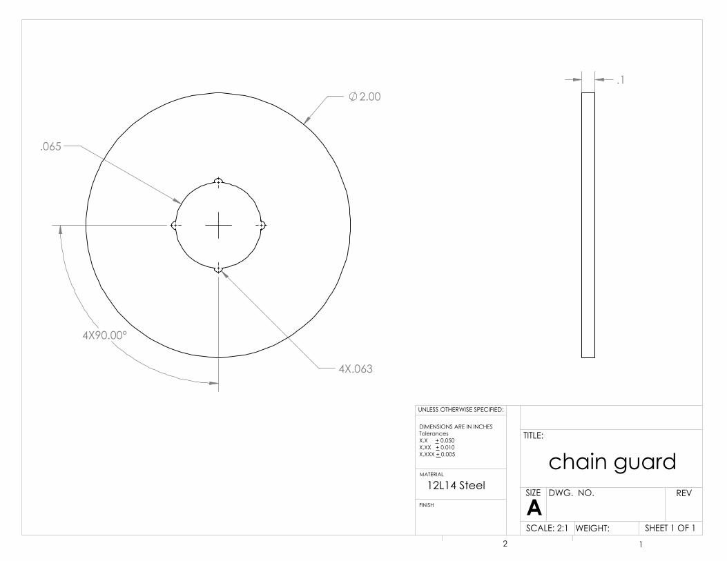
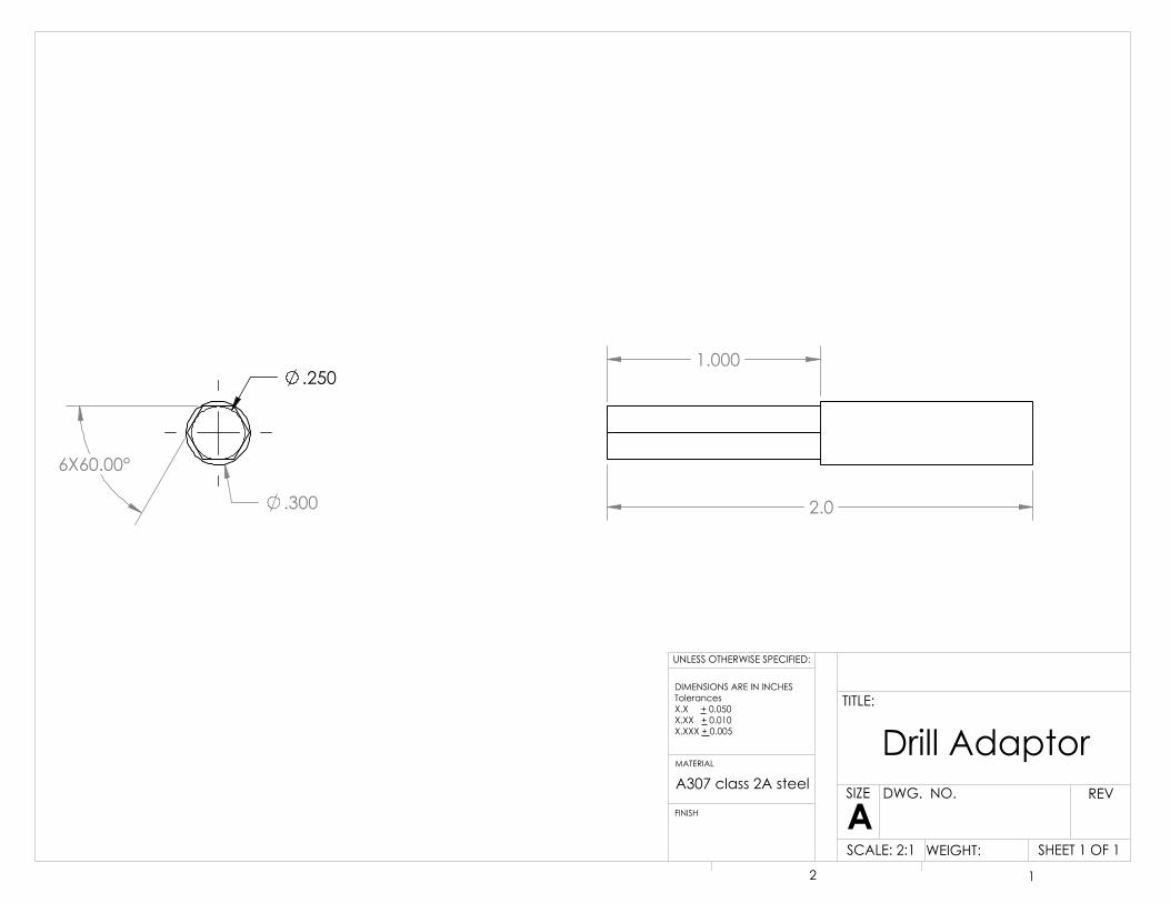
Drill Adaptor
In the original design, an ‘Ashtabula’ thru-crank bottom bracket was used for power transmission. A drill
adaptor for this bottom bracket was designed and manufactured before the decision was made to
switch to a more efficient standard bottom bracket. A new drill adaptor was designed that screws
directly into the bottom bracket and is cinched down by a simple bolt and locking washer. The
hexagonal drill bit end was kept throughout though due to its ability to lock into the drill.
Fig. 11 – Original Drill Plate Design
6

mg
Fig. 15 – Force Calculations Diagram
Vehicle Analysis
The loop around Kittredge Lake is roughly 0.25 miles long with a few troublesome sections. The course begins
with a ~600 foot long downhill. Due to an integrated freewheel in the vehicle design, the drill will not be
activated during this downhill section, allowing for speeds up to 10 mph at the bottom with no power used.
The course then follows a curving right turn and heads toward the steepest portion of the climb. In order to
ensure the vehicle’s success through this section, preliminary analysis was taken into consideration based on
a few set parameters:
Both acceptable drills for this project were considered and the Black & Decker LDX120C was chosen.
The drill is rated with a 20V motor, a maximum rotational speed of 650 rpm, and max torque of 9.6
ft∙lb1. The drill was then tested with the Idea Forge torque tester and achieved a max torque of 8.0
ft∙lb and a stall torque of 6.0 ft∙lb.
The problem portion of the hill was estimated at a grade of 12.3%, analogous to a 7⁰ slope. This
steep section stretched for nearly 60 feet.
A rough estimate for the weight of the bike resulted in ~195 lbs. This estimate was based on a rider
weight of 150 lbs, a prefabricated bike weight of 20 lbs, and a fabricated part weight of 25 lbs.
The vehicle design has an integrated derailleur to allow for efficient drill power use. This will also allow to
utilize and advantageous gear ratio during the steep portion of the climb. A force balance was calculated on
this slope, assuming a constant velocity throughout:
∑ 𝐹𝑥 = 0 = 𝐹𝑑𝑟𝑖𝑙𝑙 − 𝑚 ∗ 𝑔 ∗ 𝑠𝑖𝑛𝜃; 𝐹𝑑𝑟𝑖𝑙𝑙 = (𝜏𝑑𝑟𝑖𝑙𝑙 ∗ 𝐺𝑅)
𝑟𝑤ℎ𝑒𝑒𝑙⁄ (Norton)
This resulted in a necessary gear ratio (GR) of 4.29 to drive the hill at constant velocity. However, based on a
design limitation of an 11 tooth front chain ring and 44 tooth rear chain ring, the vehicle is limited to a GR of
4. An energy balanced was carried out to estimate the velocity decrease based on this lower gear ratio.
1
2𝑚 ∗ 𝑣0
2 + 𝐹𝑑𝑟𝑖𝑙𝑙,𝐺𝑅′ ∗ 𝑑 =1
2𝑚 ∗ 𝑣𝑓
2 + 𝑚 ∗ 𝑔 ∗ ∆ℎ (Norton)
Results were tabulated for various 𝑣0 values (speed entering the hill) and 𝑣𝑓 values (speed at the top of the
hill). Based on these calculations, a minimum 𝑣0 of 3.85 mph is necessary to reach the top of the hill,
resulting in a 𝑣𝑓 of 0 mph. However, based on test runs using a bike as the vehicle’s substitute, a 𝑣0 value of
8.9 mph was estimated, resulting in a 𝑣𝑓 of 8 mph.
7

Critical components
The most important part of the bike was the drill adaptor. This piece transfers the power from the drill
to the front sprocket. Failure here would result in complete failure as the drill could not provide power
for the vehicle.
The drill adaptor is a half threaded, half hex shaft. The thinnest part, and therefor most likely to fail, is
the hexagonal extension which connects to the drill. This regular hexagon has a side to side diameter of
0.25” and is made of A307 class 2A steel. The max torque of the selected drill was measured at 8 ft∙lb.
This power creates the maximum force that the drill adaptor will experience. The max shear stress in
torsion for the drill rod is calculated by the equation:
𝜏𝑚𝑎𝑥 = 𝑇𝑟𝐽⁄ (Norton)
The max shear stress on the shaft is 28,855.5 psi.
A307 class 2A steel has a shear strength of 60,000 psi which adjusts to 34,662 psi in torsion. The factor
of safety for the drill adapter is calculated as follows:
𝑛 =𝑆𝑦𝑠
𝜏𝑚𝑎𝑥⁄ (Norton)
This results in a factor of safety of 1.2. While this factor of safety is low, the maximum torque of the drill
will never be reached during the bike trials. Also, with only a few necessary trials, fatigue was not a
concern, instilling confidence in the somewhat low factor of safety.
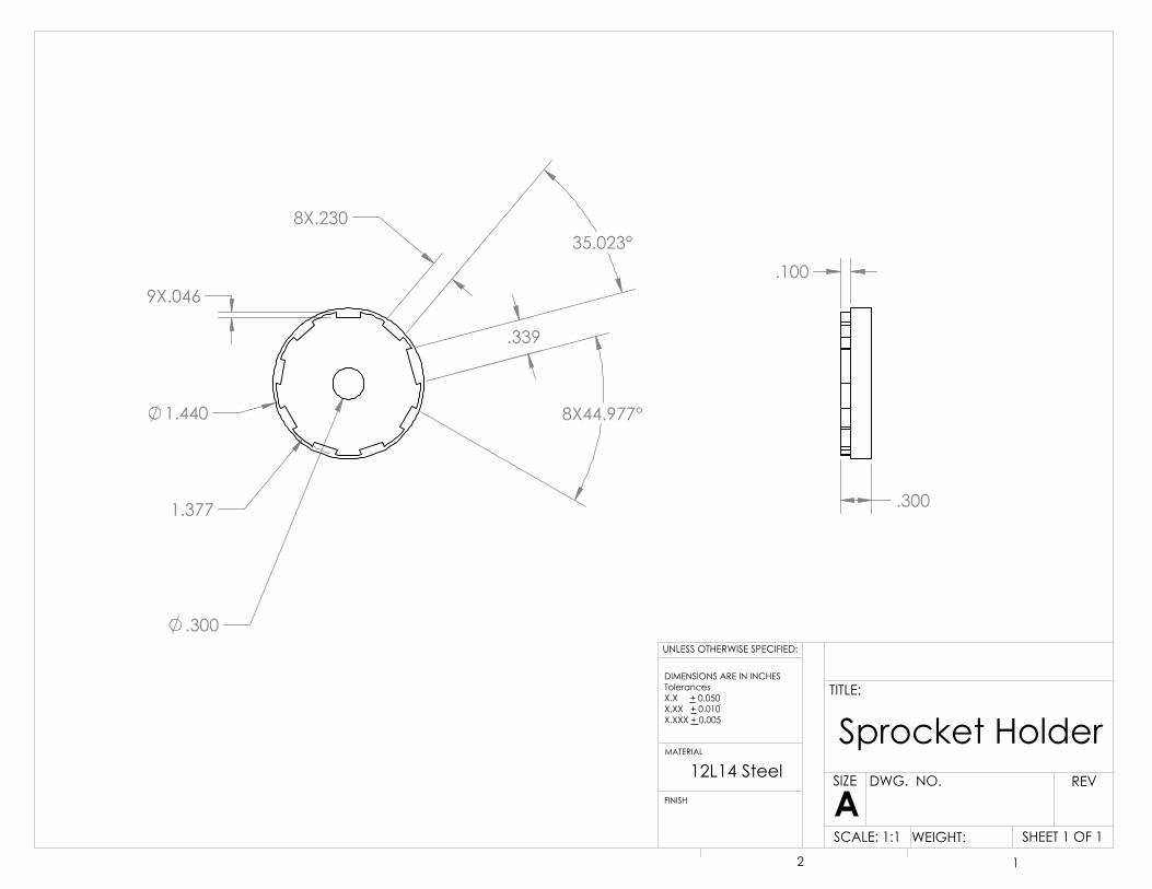
Another component undergoing a high amount of stress is the sprocket holder. This piece uses splines to
transfer the drill torque to the front sprocket. Failure would result in a spinning bottom bracket but no
vehicle movement.
The sprocket holder has 9 teeth with a diametral pitch of 1.33 inches. The spline length is 0.1 inches and
it must transfer a max torque of 8 ft∙lbs. The max shear stress in torsion for the sprocket holder is
calculated by the equation:
𝜏𝑚𝑎𝑥 = 16𝑇𝜋𝑑𝑝2𝑙⁄ (Norton)
The max shear stress on a tooth is 106.77 psi
12L14 steel has a shear strength of 70,000 psi which adjusts to 40,390 psi in torsion. The factor of safety
for the part is calculated as follows:
𝑛 =𝑆𝑦𝑠
𝜏𝑚𝑎𝑥⁄ (Norton)
This results in a factor of safety of 378. This is high but the dimensions are driven by our front sprocket.
8

Fabrication
We strived to design a vehicle that focused on simplicity and achievability. With that in mind, we settled
upon a design that required minimal manufacturing. However, there was a trade-off with an increased
amount of assembly. Our manufactured parts are the frame, drill adaptor, drill plate, tie rods, and steer
tubes.
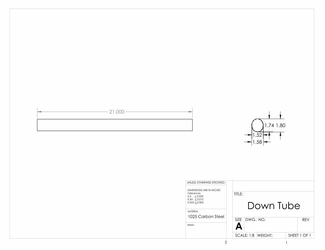
The frame was made from existing bike frames, a Schwinn and a Roadmaster, and a 1’ length of steel
tubing with 1.5“ outer diameter and 1.26” inner diameter. Assembly of the frame was done in three
stages: first, the steer chassis was welded together; second, the rear triangle and down tube/support
tube were welded together; third, the steer chassis was welded to the down tube. The steer chassis was
made from three 3.9” head tubes (cut from our purchased length of steel tubing) connected in-line by
the Schwinn down tube which was cut in half. The rear triangle of the Schwinn bicycle was cut from the
rest of the bike and kept intact to support our rear wheel and drivetrain. Extending forward off of the
bottom bracket housing of that rear triangle is the former down tube of the Roadmaster bike, which was
cut to a useable length and welded. The former top tube of the Roadmaster was also cut to length and
welded to both the seat tube and the down tube to form a triangular support. Once the two portions
were completed, the free end of the down tube was welded to the central head tube of the steer chassis
to create a T-shaped completed frame.
The drill adapter was manufactured from a 2” diameter 12L14 steel bar and a 2” length of A307 class 2A
threaded stock. In order to secure the 11-tooth front chain ring to the bottom bracket and prevent
lateral chain slippage an adaptor and chain guide were machined using the 12L14 steel. The adaptor was
press-fit into the chain ring and threaded onto the section of threaded stock. A stopper nut was butted
against the adaptor to prevent loosening during operation. The outboard end of the threaded stock was
cut into a hexagonal shape to allow for a secure interface with the drill chuck. The chain guide was
press-fit onto the spline of the bottom bracket. Finally, the threaded stock was threaded into the
bottom bracket creating a solid unit that could be rotated in unison by the drill.
The drill plate was manufactured from one piece of 6061 aluminum plating. The piece was cut into two
sections and bolted into an L-shape. Holes were placed such that two U bolts could fix the drill plate to
the bike and four bolts kept the L-shape of the plate. Six slots were cut in the plate to accommodate
three hose clamps that fastened the drill securely to the plate.
The tie rods were made from 3/8” 12L14 steel bar stock cut to 7” lengths. The ends were drilled and
tapped to accept ¼”x28x1” set screws which were then threaded onto clevis attachments. Each clevis
was then attached to each hole in the steer tube tabs.
The three steer tubes were made from the seat tube of the Roadmaster and the top tube of the Schwinn
which were both mild steel and had outer diameters of 1.125” to fit in standard thread-less bicycle
headsets. The center steer tube was cut to 13” and the outer tubes were cut to 5.9”. The outer steer
tubes had a 0.5” thru-hole bored 0.6” from one end and perpendicular to the tube to accept the axels of
the front wheels. To one end of each outer tube were welded steer tabs that were machined to
9
1.6”x2.2” from ¼“ 12L14 steel flat stock with a ¼“ hole in the center of one end to accommodate the
clevis pins. The center steer tab was machined to 1.6”x3.14” out of the same ¼” flat stock with two
holes on each end, again to accommodate the clevis pins. The center steer tube was then welded to the
center of that tab.
Standard Parts
Frame o BMX pegs o Rear triangle o Bottom bracket housing
Power Drive o Drill – BDCD 120 o Front chain ring, rear cassette,
rear wheel and tire, o rear derailleur, chain, brake
assemblies o U- bolts o 9 – bearing rings vintage style
Steering o Handle bars o Stem o 20” BMX wheels o Neco threadless headsets o Forged clevis rod ends ¼” – 28
Custom Parts
Frame o Chassis/support tubes
Power Drive o Drill plate o Drill connector
Steering o Tie rods o Tabs o Head tubes o Steer support tubes o Steering Column
10

Vehicle Testing and Results
Not only was the vehicle required to drive, but it also had to meet several other specifications which
were outlined in the project description and developed by the team. The most crucial specifications
included height limitations, power and weight requirements, and ability to complete the designated
course.
The final vehicle and rider were required to extend no more than three feet and six inches off of the
ground. This specification was a key component in the design consideration. To test this criterion, the
team tied a string across two poles 3 feet 6 inches above the ground. The team pushed the vehicle with
the driver in it under the string without powering the vehicle with the drill. If any part of the vehicle or
the rider touched the string, the test would have been considered a failure. If the test were failed, the
team would have needed to either make a design change or adjust the driver’s position. On the first
test, the vehicle and rider were 9 inches below the string so the test did not need to be repeated.
Once the height test was completed, the design team moved on to the power to weight ratio criterion.
The power to weight ratio was an important component to consider because if it were too low, the
vehicle would not be able to complete the course. Drill power was calculated using torque and RPM
measurements. Please refer to the ‘Vehicle Analysis’ section for more information on this requirement.
The weight of the vehicle was measured using the scale in the machine shop. These figures allowed the
design team to calculate the power to weight ratio, but the vehicle still needed to be tested on the
course. The driver was able to complete the course in 104 seconds so the power to weight practical test
was passed. The driver also was able to steer with both hands at all times and kept all three wheels on
the ground thus meeting two other project criterion. Please refer to the test plan and specific pass/fail
criterion below for more information on testing criteria.
Requirement: Vehicle height less than 3’ 6”
Test: Team will build a structure with a string tied across at 3’ 6” and the team will push the vehicle with the driver in it under the string without powering the vehicle with the drill.
Evaluation (Pass/Fail):
Vehicle moves under string without touching = pass
Vehicle or driver touches string = fail
Requirement: Vehicle is safe.
Test: Driver will mount vehicle and shift his weight from side to side while feeling to see if any supporting parts are loose or unstable. The driver will then test the steering system by turning the handlebars. The driver will then test the drill and drive train to see if the vehicle will move forward. The driver will then test the brakes. All team members will look at vehicle from all sides to observe any signs of failure during the test process.
11

Evaluation (Pass/Fail):
All tested components function as intended without signs of failure = pass
A component malfunctions or shows signs of failure = fail
Requirement: High power to weight ratio
Test: The team will use two to three luggage scales to measure the weight of the vehicle. The team will also measure the drill’s power in the Idea Forge. The team will compare these two values and decide if it is an acceptable ratio.
Evaluation (Pass/Fail):
Team accepts the measured ratio = pass
Team chooses to decrease vehicle weight = fail
Requirement: Complete 1,370’ long obstacle course with 45’ elevation change
Test: The driver will begin at the eastern end of the Kittredge ponds with a fully charged battery and will actuate the drill to power the vehicle. The driver will attempt to complete the course while monitoring the vehicle’s functionality. The team will time the driver and will follow along. On the first attempt, the driver will go at a fairly slow pace to maintain control and ensure no components show signs of failure. On subsequent attempts, the driver will start with a fully charged battery and will use a phone application to monitor the vehicle’s speed and position on the course. The team will analyze these results to make improvements to the driving efficiency.
Evaluation (Pass/Fail):
Driver completes course under the power of one battery in under 10 minutes = pass
Driver cannot complete course under the power of one battery in under 10 minutes = fail
Requirement: Two hands must be used for steering at all times
Test: Driver will ensure both hands stay on the handlebars while attempting the course.
Evaluation (Pass/Fail):
Both hands remain gripping handlebars during the entire course = pass
At least one hand must be removed from the handlebars at some point while attempting the course = fail
Requirement: Wheelbase must be at least 30”
Test: The team will use a tape measure to find the distance from the center of the front axle to the center of the rear axle.
12
Evaluation (Pass/Fail):
The wheelbase is greater than or equal to 30” = pass
The wheelbase is less than 30” = fail
Requirement: More than two wheels
Test: Team members will ensure that the vehicle has more than three wheels.
Evaluation (Pass/Fail):
Vehicle has more than three wheels = pass
Vehicle does not have more than three wheels = fail
Requirement: The vehicle must be powered by a Black and Decker BDCDMT120 cordless electric drill.
Test: The team will be sure to use the specified drill.
Evaluation (Pass/Fail):
Correct drill is used = pass
Incorrect drill is used = fail
During subsequent test runs, two issues arose. The first issue was the front wheels wobbling on the
downhill portion of the course. It was discovered that the front left wheel was not true and the steering
tube had some play. The wheel was straightened using a spoke wrench and the bearings were repacked
in the steering headset. This decreased the amount of wobble experienced during the downhill portion
of the course, but the issue was not completely ameliorated because there were gaps in the tie rod
clevises which would have been difficult to correct. The second problem experienced during testing
involved the drill cutting out while being actuated. The drill Operation Manual stated that the drill will
cut power if the torque demand exceeds the torque limit of the drill. To decrease the torque demand,
the team decided to change the gear ratio from 3.1:1 to 4:1. The drill continued to cut out with this gear
ratio so the team changed the gear ratio to 4.8:1. While testing the 4.8:1 gear ratio the team found a
problem with the drill actuator. Initially, the drill was actuated by extending the wires from the drill and
fastening the trigger to the handlebars. The team found that a zip tie was keeping the trigger from being
fully depressed. The team experimented with fastening the trigger on to the handlebar in several
different ways before eventually deciding to actuate the trigger manually. The manual actuation caused
the drill to cut out less frequently, but the vehicle still did not perform properly. The team examined the
drive train more closely and found that a sprocket in the derailleur had locked up. A bushing had fallen
out during assembly causing the sprocket to overtighten. The team replaced the bushing and found that
the original gear ratio of 3.1:1 was enough for the vehicle to summit the hill.
13
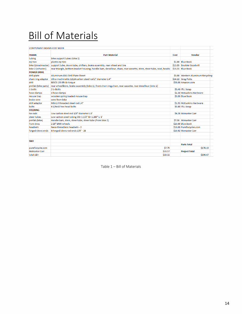
Table 1 – Bill of Materials
Bill of Materials
14
References
"Blackanddecker.com." Blackanddecker.com. N.p., n.d. Web. 28 Oct. 2014.
Norton, Robert L. Machine Design: An Integrated Approach. Vol. 5. Upper Saddle River, NJ:
Pearson Prentice Hall, 2006. Print.
12L14 drill connector 90075K46 http://www.mcmaster.com/#grade-12l14-steel/=v0ymux
Forged clevis rod ends 6071K12
http://www.mcmaster.com/#catalog/120/1216/=v12uvu
Low-carbon steel tubing 7767T431
http://www.mcmaster.com/#catalog/120/3691/=v12v7q
Low-carbon steel rods – 8920K135
http://www.mcmaster.com/#catalog/120/3691/=v12vnb
Neco threadless headsets
https://www.purefixcycles.com/products/neco-head-set
15
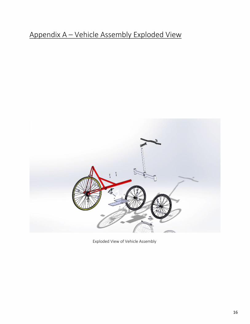
Appendix A – Vehicle Assembly Exploded View
Exploded View of Vehicle Assembly
16
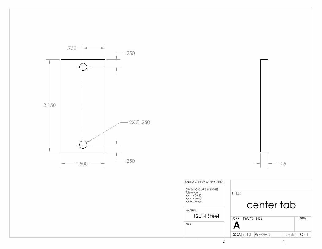
3.150
1.500
2X .250
.250
.250 .750
.25
center tab
SHEET 1 OF 1
UNLESS OTHERWISE SPECIFIED:
SCALE: 1:1 WEIGHT:
REVDWG. NO.
ASIZE
TITLE:
FINISH
MATERIAL
DIMENSIONS ARE IN INCHESTolerancesX.X + 0.050X.XX + 0.010X.XXX + 0.005
2 1
12L14 Steel
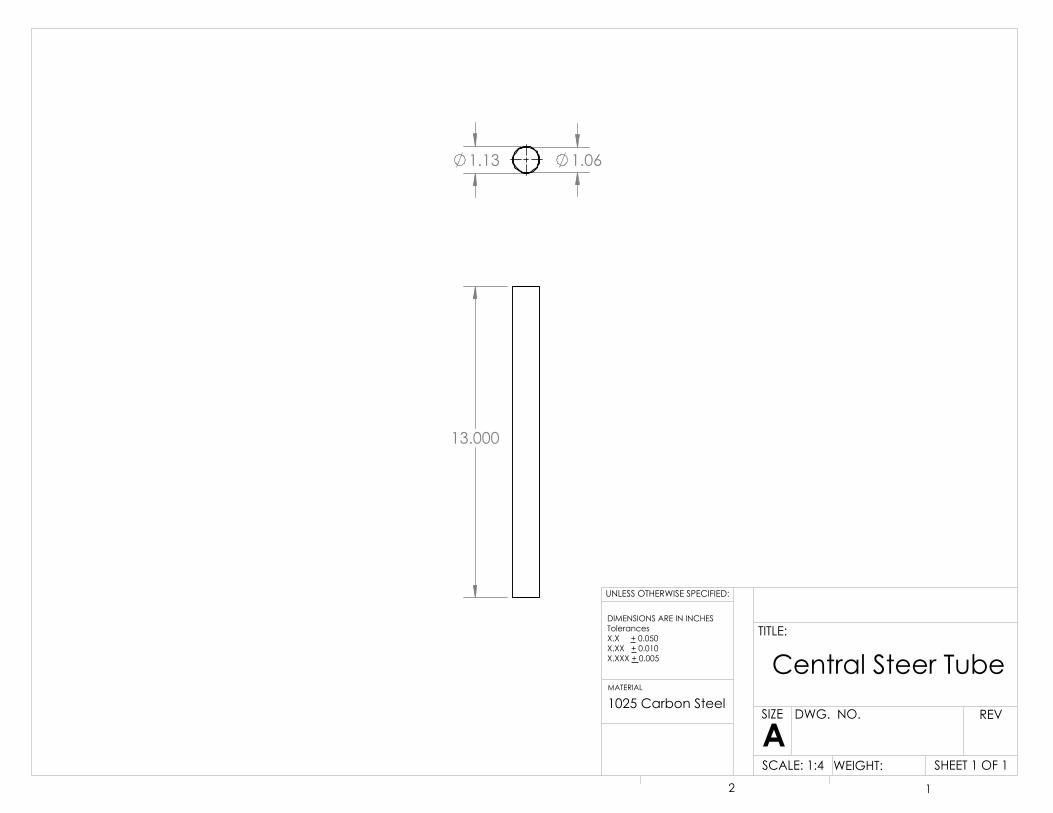
13.000
1.13 1.06
Central Steer Tube
SHEET 1 OF 1
UNLESS OTHERWISE SPECIFIED:
SCALE: 1:4 WEIGHT:
REVDWG. NO.
ASIZE
TITLE:
MATERIAL
DIMENSIONS ARE IN INCHESTolerancesX.X + 0.050X.XX + 0.010X.XXX + 0.005
2 1
1025 Carbon Steel
4X.063
.065
2.00
4X90.00°
.1
chain guard
SHEET 1 OF 1
UNLESS OTHERWISE SPECIFIED:
SCALE: 2:1 WEIGHT:
REVDWG. NO.
ASIZE
TITLE:
FINISH
MATERIAL
DIMENSIONS ARE IN INCHESTolerancesX.X + 0.050X.XX + 0.010X.XXX + 0.005
2 1
12L14 Steel
.300
.100
1.440
.339
8X.230 35.023°
8X44.977°
9X.046
1.377
.300
Sprocket Holder
SHEET 1 OF 1
UNLESS OTHERWISE SPECIFIED:
SCALE: 1:1 WEIGHT:
REVDWG. NO.
ASIZE
TITLE:
FINISH
MATERIAL
DIMENSIONS ARE IN INCHESTolerancesX.X + 0.050X.XX + 0.010X.XXX + 0.005
2 1
12L14 Steel
21.000
1.58
1.80
1.52
1.74
Down Tube
SHEET 1 OF 1
UNLESS OTHERWISE SPECIFIED:
SCALE: 1:8 WEIGHT:
REVDWG. NO.
ASIZE
TITLE:
FINISH
MATERIAL
DIMENSIONS ARE IN INCHESTolerancesX.X + 0.050X.XX + 0.010X.XXX + 0.005
2 1
1025 Carbon Steel
.250
2.0
1.000
.300
6X60.00°
Drill Adaptor
SHEET 1 OF 1
UNLESS OTHERWISE SPECIFIED:
SCALE: 2:1 WEIGHT:
REVDWG. NO.
ASIZE
TITLE:
FINISH
MATERIAL
DIMENSIONS ARE IN INCHESTolerancesX.X + 0.050X.XX + 0.010X.XXX + 0.005
2 1
A307 class 2A steel

0.188
0.5
00
4X 0.25
0
0.7
5 0
.81
1.0
0
2.8
1
5.0
0 5
.30
6.3
0 0
1.50
2.49
3.71
4.59
5.24
7.42 7.36
7.95
*See note below
0.25
6061 Aluminum
Drill Plate 1
SHEET 1 OF 1
UNLESS OTHERWISE SPECIFIED:
SCALE: 1:2 WEIGHT:
REVDWG. NO.
ASIZE
TITLE:
FINISH
MATERIAL
DIMENSIONS ARE IN INCHESTolerancesX.X + 0.050X.XX + 0.010X.XXX + 0.005
2 1
*All rectangular slots are equally dimensioned

4X
0.2
50
2X
0.3
13
4X
0.2
50
0.188 0.188
0.5
00
0.5
00
0
1.0
75
2.0
00
2.9
25
8.1
60
10.
348
12.
160
12.
348
13.
160
0 0.625 1.000 1.605 1.720
3.105 3.210
4.085 4.710
0.25
6061 Aluminum
Drill Plate 2
SHEET 1 OF 1
UNLESS OTHERWISE SPECIFIED:
SCALE: 1:5 WEIGHT:
REVDWG. NO.
ASIZE
TITLE:
FINISH
MATERIAL
DIMENSIONS ARE IN INCHESTolerancesX.X + 0.050X.XX + 0.010X.XXX + 0.005
2 1

6.000
1.13 1.06
Left/Right Steer Tube
UNLESS OTHERWISE SPECIFIED:
SCALE: 1:2
REVDWG. NO.
ASIZE
TITLE:
FINISH
MATERIAL
DIMENSIONS ARE IN INCHESTolerancesX.X + 0.050X.XX + 0.010X.XXX + 0.005
2 1
1025 Cold Rolled Steel

4.000 1.75
1.50
Steer Chassis Column
SHEET 1 OF 1
UNLESS OTHERWISE SPECIFIED:
SCALE: 1:1 WEIGHT:
REVDWG. NO.
ASIZE
TITLE:
FINISH
MATERIAL
DIMENSIONS ARE IN INCHESTolerancesX.X + 0.050X.XX + 0.010X.XXX + 0.005
2 1
1025 Carbon Steel

.415 .415
R.75 R.75 1.25
1.15
1025 Carbon Steel
Steer Chassis Cross Beam
SHEET 1 OF 1
UNLESS OTHERWISE SPECIFIED:
SCALE: 1:2 WEIGHT:
REVDWG. NO.
ASIZE
TITLE:
FINISH
MATERIAL
DIMENSIONS ARE IN INCHESTolerancesX.X + 0.050X.XX + 0.010X.XXX + 0.005
2 1

.250
.250
2.200
1.500
.750
.250
Steer Tab
SHEET 1 OF 1
UNLESS OTHERWISE SPECIFIED:
SCALE: 1:1 WEIGHT:
REVDWG. NO.
ASIZE
TITLE:
FINISH
MATERIAL
DIMENSIONS ARE IN INCHESTolerancesX.X + 0.050X.XX + 0.010X.XXX + 0.005
2 1
12L14 Steel

7.000
.7 .7
.372 1/4-28 tapped hole
Low Carbon Steel
Tie Rod
SHEET 1 OF 1
UNLESS OTHERWISE SPECIFIED:
SCALE: 1:2 WEIGHT:
REVDWG. NO.
ASIZE
TITLE:
FINISH
MATERIAL
DIMENSIONS ARE IN INCHESTolerancesX.X + 0.050X.XX + 0.010X.XXX + 0.005
2 1

Appendix C - Preliminary Calculations
Gear Ratio // Power Needs
∑ 𝐹𝑥 = 0 = 𝐹𝑑𝑟𝑖𝑙𝑙 − 𝑚 ∗ 𝑔 ∗ 𝑠𝑖𝑛𝜃; 𝐹𝑑𝑟𝑖𝑙𝑙 = (𝜏𝑑𝑟𝑖𝑙𝑙 ∗ 𝐺𝑅)
𝑟𝑤ℎ𝑒𝑒𝑙⁄
(𝜏𝑑𝑟𝑖𝑙𝑙 ∗ 𝐺𝑅)𝑟𝑤ℎ𝑒𝑒𝑙
⁄ = 𝑚 ∗ 𝑔 ∗ 𝑠𝑖𝑛𝜃; 𝜏𝑑𝑟𝑖𝑙𝑙 = 72 in ∙ lb, 𝑟𝑤ℎ𝑒𝑒𝑙 = 13 𝑖𝑛, 𝑚𝑔 = 195 𝑙𝑏𝑠, 𝜃 = 70
𝐺𝑅 =(195 𝑙𝑏𝑠) ∗ sin(7o) ∗ (13 𝑖𝑛)
(72 in ∙ lb)= 4.29
1
2𝑚 ∗ 𝑣0
2 + 𝐹𝑑𝑟𝑖𝑙𝑙,𝐺𝑅′ ∗ 𝑑 =1
2𝑚 ∗ 𝑣𝑓
2 + 𝑚 ∗ 𝑔 ∗ ∆ℎ
𝑚 = 6.09 𝑠𝑙𝑢𝑔𝑠, 𝐺𝑅′ = 4, 𝐹𝑑𝑟𝑖𝑙𝑙,𝐺𝑅′ = 22.15 𝑙𝑏𝑠, 𝑑 = 60 𝑓𝑡, ∆ℎ = 60 sin(70) = 7.3 𝑓𝑡
𝑣0 [𝑓𝑡 𝑠⁄ ] 𝑣𝑓 [𝑓𝑡 𝑠⁄ ] 𝑣0 [𝑚𝑝ℎ] 𝑣𝑓 [𝑚𝑝ℎ]
5.65 0.08 3.85 0.05
6.00 2.02 4.09 1.38
7.00 4.13 4.77 2.82
8.00 5.66 5.45 3.86
9.00 7.01 6.14 4.78
10.00 8.25 6.82 5.63
11.00 9.44 7.50 6.44
12.00 10.59 8.18 7.22
13.00 11.71 8.86 7.98
14.00 12.81 9.55 8.74
15.00 13.90 10.23 9.47
Kittredge Lake Elevation Profile – MapMyRide App

Critical Components
Drill Adaptor factor of safety:
𝑇 = 8 ftlb, r = 0.25/2 = 0.125”, Side length a = 0.14”, Sy = 60000psi, Sys = 0.577 * Sy = 34662 psi
𝐼𝑜 =5√3
8𝑎4 = 𝐼𝑥 = 𝐼𝑦
𝐽 = 𝐼𝑥 + 𝐼𝑦 = 2𝐼𝑜
𝐽 =5√3
40.144
J = 0.0004158 in^4
𝜏 max = 𝑇𝑟/𝐽
𝜏 max =(8𝑓𝑡𝑙𝑏 ∗
12𝑖𝑛𝑓𝑡
) (0.125𝑖𝑛)
0.0004158𝑖𝑛4
Τmax = 28855.49 psi
𝑛 = 𝑆𝑦𝑠/𝜏𝑚𝑎𝑥
𝑛 =34662𝑝𝑠𝑖
28855.49𝑝𝑠𝑖= 1.2
Steer Tube factor of safety:
l = 0.1”, T = 8ftlb, d = 1.33”, N = 9, Sy = 70000psi, Sys = 0.5777*Sy = 40390psi
𝑑𝑝 = 𝑁/𝑑
dp = 6.7669 1/in
𝜏𝑚𝑎𝑥 = 16𝑇𝜋𝑑𝑝^2𝑙⁄
𝜏𝑚𝑎𝑥 =16(96𝑖𝑛𝑙𝑏)
𝜋(6.7669)^2(0.1)⁄
Tmax = 106.77 psi
𝑛 = 𝑆𝑦𝑠/𝑇𝑚𝑎𝑥
𝑛 =40390
106.77= 378.28
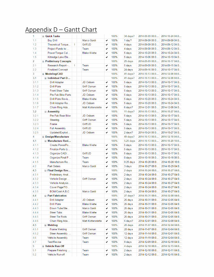
Appendix D – Gantt Chart


Appendix E – Test Data