Embed Size (px)
Citation preview

Deployment Guide
© 2010 Cisco and/or its affiliates. All rights reserved. This document is Cisco Public Information. Page 1 of 14
Dräger Patient Monitoring Deployment in the Cisco Unified Wireless Network Infrastructure
This document provides the design considerations and deployment guidelines for the Dräger Patient Monitoring solution within the Cisco® Unified Wireless Network infrastructure.
Note: Support for Dräger products should be obtained directly from Dräger support channels. Cisco Technical Assistance Center (TAC) staff are not trained to resolve problems related to Dräger products.
This guide addresses the configuration parameters that are particular to Dräger patient monitoring devices in a managed wireless architecture. Basic network design, wired multicast recommendations, or basic protocol design concepts are beyond the scope of this document. To get the most out of this deployment guide, you should have fundamental understanding of network architecture and protocol design concepts.
We recommend that you read and become familiar with the terms and concepts presented in the following Cisco documents:
● Wireless Considerations in Healthcare Environments: http://www.cisco.com/web/strategy/docs/healthcare/wireless_hc_environ061208.pdf
● Wireless and Network Security Integration Solution Design: Guide: http://www.cisco.com/en/US/partner/docs/solutions/Enterprise/Mobility/secwlandg20/sw2dg.html
● Cisco Wireless LAN Controller Configuration Guide, Release 5.2: http://www.cisco.com/en/US/docs/wireless/controller/5.2/configuration/guide/Controller52CG.html
● Cisco IP Telephony Solution Reference Network Design Guide: http://www.cisco.com/en/US/docs/voice_ip_comm/cucme/srnd/design/guide/models.html
These documents are available at http://www.cisco.com with the proper login permissions.

Deployment Guide
© 2010 Cisco and/or its affiliates. All rights reserved. This document is Cisco Public Information. Page 2 of 14
Executive Summary
Wireless patient monitors are not a new phenomenon. Patient telemetry has been done over dedicated wireless channels since the early 1970s, first using analog transmission schemes and then transitioning to digital in the 1990s. The advent of 802.11-compatible wireless patient monitors has unlocked the many advantages of using a standard, off-the-shelf wireless technology and has also presented some implementation challenges due to the life-critical nature of the application.
Whereas a dropped packet or two may slow down a file transfer or webpage access, or may result in a garbled word in a wireless voice-over-IP (VoIP) call, a lost packet in a patient monitoring application may delay alerting nursing staff to an urgent condition, with the potential of serious patient injury. With this understanding, a strong radio policy is critical for such applications running in an 802.11 environment, where packet loss must be kept to a minimum.
This guide provides design and deployment guidelines to help ensure a successful and safe deployment of the Dräger Patient Monitoring solution using the Cisco Unified Wireless Network infrastructure.
Note: The Dräger Patient Monitoring solution requires Cisco Unified Wireless LAN Controller software 4.2 or later. Earlier versions of the controller software flood multicast packets to all access points, resulting in collisions and data loss.
The Dräger Solution
The following sections provide an overview of the Dräger medical devices that can be integrated into a Cisco Unified Wireless Network.
Infinity Bedside Patient Monitoring Solution Infinity bedside patient monitors provide comprehensive patient monitoring that includes multiple-lead ECG, SpO2, respiration, dual temperature, cardiac output, multiple invasive pressures, noninvasive blood pressure, and arrhythmia classification (see Figure 1).
Figure 1. Infinity Bedside Patient Monitors
© Dräger Medical. Image provided courtesy of Dräger Medical, Inc.
A wide range of sizes and styles—including the Infinity Delta, Gamma, Kappa, and Vista series—let a biomedical engineer tailor the system to departmental needs. These monitors bring critical information from other bedside devices to the patient monitor via the Infinity Docking Station to help the clinician make faster patient assessments. The monitor provides maximum reliability, decreased downtime, and reduced spare parts and support costs.
The Infinity Central Monitoring Solution gathers and displays information from the Infinity bedside monitors and patient-worn Infinity devices. Up to 32 patients can be simultaneously monitored and displayed on each Infinity Central Station.
The patented Pick&Go® flexibility lets Infinity monitors move with the patient (see Figure 2). When undocked, the patient monitor switches to wireless mode and continuously transmits vital signs back to the central systems. The ability to monitor patients during transport throughout the healthcare facility has become an important requirement for caregivers.

Deployment Guide
© 2010 Cisco and/or its affiliates. All rights reserved. This document is Cisco Public Information. Page 3 of 14
Figure 2. Infinity Monitors Moving with a Patient
© Dräger Medical. Image provided courtesy of Dräger Medical, Inc.
Technical Aspects of Infinity Bedside Monitoring Solutions The Infinity bedside monitoring solution uses standard IP Multicast packets for more than 90 percent of its I/O. Devices are both IP Multicast transmitters and receivers, which helps to ensure the exchange of information with all connected devices of a defined group, called a monitoring unit (MU). To prevent flooding of this traffic, both the wired and wireless portions of the network must be configured for Internet Group Management Protocol (IGMP) multicast traffic. Infinity bedside monitors constantly transmit packets at approximately 100 kbps in both wired and wireless mode.
Within a monitoring unit, four common multicast streams are created and are shared by all Infinity devices in the MU, both as transmitters and as group members. In addition, each bedside monitor transmits its own unique multicast stream of waveform pixel and vital-signs data that an Infinity Central Station uses for active display. That stream can be requested on another bedside monitor in the same MU by a clinician using the remote view feature. The waveform display occupies the lower portion of the local monitor’s screen. In this case, the multicast data flows directly between the two bedside monitors and is not routed through the Infinity Central Station.
Table 1 shows an example of the multicast addresses generated in a single monitoring unit with four bedside devices. It is highly recommended that you create an overview of utilized multicast addresses when deploying a patient monitoring installation.
Table 1. Example of Multicast Addresses for Patient Monitoring
Multicast Addresses for Monitoring Unit 5 Name service 224.127.5.255 Alarm group service 224.127.5.254 Time service 224.127.5.253 Alarm group service for ventilators 224.127.5.252 Patient data stream (first Infinity Bedside Monitor) 224.0.5.1 Patient data stream (second Infinity Bedside Monitor) 224.0.5.2 Patient data stream (Nth Infinity Bedside Monitor) 224.0.5.N
Infinity M300 Patient-Worn Solution Dräger’s innovative Infinity® M300 patient-worn monitor (Figure 3) takes telemetry monitoring to a new level. The compact, lightweight device provides the performance of a full-size patient monitor, with a built-in color display, alarm messages, and rechargeable battery. Based on industry-standard IEEE802.11b/g Wi-Fi technology, Infinity M300 provides continuous standalone monitoring—even if the patient inadvertently moves out of the hospital’s wireless network coverage area.

Deployment Guide
© 2010 Cisco and/or its affiliates. All rights reserved. This document is Cisco Public Information. Page 4 of 14
Figure 3. Infinity M300 Patient-Worn Device
© Dräger Medical. Image provided courtesy of Dräger Medical, Inc.
Technical Aspects of the Infinity M300 Solution The Infinity M300 is a wireless-only device that communicates via the Wi-Fi infrastructure, primarily with the Infinity Central Station that it is assigned to. In contrast to the Infinity Bedside Monitors, Infinity M300 communication is based on unicast IP communication only, with no use of multicast. With its utilization of the 802.11 power-save protocol, the Infinity M300 preserves battery life, thus extending its use as a patient-worn device. To ensure optimal performance, M300s require a separate VLAN so the devices are not roused from their power-saving mode by other broadcast or multicast traffic.
The Infinity M300 can be seen as a client to the Infinity Central Station, which from a clinical perspective, acts as the primary alarming device. In addition, the Infinity Central Station serves as a communication proxy, retransmitting the M300’s TCP/IP data as multicast to other Infinity Bedside Patient Monitors in the same monitoring unit.
Infinity Remote Access Solution Dräger offers a software solution called Infinity WinView/WebView, which enables doctors and nurses to display and access “near-real-time” data on a desktop PC, or while on the move with Microsoft Pocket PC devices (see Figure 4). This flexibility, combined with the Cisco Lightweight Access Point Protocol (LWAPP) wireless infrastructure, puts doctors and nurses closer to the needs of their patients.
Figure 4. Infinity WinView/WebView Displayed on a Pocket PC Device
© Dräger Medical. Image provided courtesy of Dräger Medical, Inc.

Deployment Guide
© 2010 Cisco and/or its affiliates. All rights reserved. This document is Cisco Public Information. Page 5 of 14
Technical Aspects of the Infinity Remote Access Solution Mobile smart clients or laptops used as part of the remote access solution are controlled and maintained by the hospital’s IT department. They may not be subject to the same strict network deployment limitations required by medical devices. Dräger does not specify network requirements for remote access clients. From a deployment perspective, the mobile devices are separated by a VLAN and Service Set Identifier (SSID) from the bedside monitors and telemetry devices. Vital signs are delivered to clients through the Infinity Network by the Infinity Gateway server.
Wireless Infrastructure Planning
RF Design Planning of a wireless network—including selection of access points, positioning of antennas, adjusting power levels and channels—requires expertise in the wireless system and in RF. Cisco provides specific documents and training, which should be considered before deploying any wireless devices in a Wi-Fi network.
Like other medical device manufacturers, Dräger defines very strict requirements for wireless networks, because the patient’s safety may rely on successfully transmitted vital data or alarm messages. Thus, the requirements listed below are mandatory and have to be met before going live with Dräger patient monitors.
RF Requirements for Infinity Delta and Gamma Series Patient Monitors
When switching to wireless communication, Infinity Bedside Patient Monitors, just like every other wireless device, require a solidly designed RF infrastructure to be able to transmit data. In the case of patient monitors, a permanent connection with minimal or no drop-offs has become a requirement.
Table 2 lists the wireless specifications for Infinity Delta and Gamma Series products working within the Cisco Unified Wireless Network.
Note: Specifications are version-specific and subject to change with new releases. Check with Dräger for the latest data at http://www.draeger.com.
Table 2. Specifications for the Dräger Infinity Delta and Gamma Series Monitors
Infinity Network Wireless Specification Infinity Delta Series (VF8 and higher)
Infinity Gamma Series (VF7 and higher)
Device specifications Wireless Layers 1 and 2 Protocol IEEE802.11b/g IEEE802.11b/g Wireless channels selection 1 to 13 1 to 13 Wireless Security Protocol Wired Equivalent Privacy (WEP) 128-bit,
Wi-Fi Protected Access 2 (WPA2) WEP 128-bit, WPA2
IEEE 802.11b rates supported 11, 2, 5.5, 11 Mbps 11, 2, 5.5, 11 Mbps IEEE 802.11g rates supported 6, 9, 12, 18, 24, 36, 48, 54 Mbps 6, 9, 12, 18, 24, 36, 48, 54 Mbps Transmit power of device 15 dBm 15 dBm Receiver characteristics Up to 54 Mbps -70 dBm -70 dBm Infrastructure settings in coverage area* Maximum transmit power on access point 15 dBm 15 dBm Maximum number of Dräger devices per access point supported
6 6
1 In order to support the maximum number of devices specified, the data rate must be 2 Mbps or higher.

Deployment Guide
© 2010 Cisco and/or its affiliates. All rights reserved. This document is Cisco Public Information. Page 6 of 14
Infinity Network Wireless Specification Infinity Delta Series (VF8 and higher)
Infinity Gamma Series (VF7 and higher)
Quality-of-service information Average network traffic generated per device 100kbits/sec 75kbits/sec Data packet size Alternates between 512 bytes and 1460
bytes Alternates between 512 bytes and 1460 bytes
Installation and design constraints Maximum node capacity 1024 1024 IP address assignment Static Static IP communication protocols used TCP, User Datagram Protocol (UDP),
Internet Control Message Protocol (ICMP), IP Multicast
TCP, UDP, ICMP, Multicast
IP communication ports used 515, 1950, 2000, 2050, 2100, 2150, 6000, 6050, 9200, 9250
515, 1950, 2000, 2050, 2100, 2150, 6000, 6050, 9200, 9250
Dedicated SSID required Yes Yes Maximum SSID character length 32, A to Z, upper- and lowercase supported,
0 to 9 32, A to Z, upper and lower case supported, 0 to 9
VLAN Dräger Multicast VLAN Dräger Multicast VLAN Client cards Ambicom WL541 client adapter Ambicom WL541 client adapter
Note: 802.11b/g and WPA2 is only supported with the Ambicom PCMCIA card but only 802.11b and WEP is supported with the Cisco Aironet® 350 Series card that was used in the past.
RF Requirements for the Infinity M300 Monitor When switching to wireless communication, Infinity Bedside Patient Monitors, just like every other wireless device, require a solidly designed RF infrastructure to be able to transmit data. In the case of patient monitors, a permanent connection with minimal or no drop-offs has become a requirement.
Table 3 lists the wireless specifications for Dräger Infinity M300 monitors working within the Cisco Unified Wireless Network.
Note: Specifications are version-specific and subject to change with new releases. Check with Dräger for the latest data at http://www.draeger.com.
Table 3. Specifications for the Dräger Infinity M300 Monitor
Infinity Network Wireless Specification Infinity M300 (VF8.6 and later) Device specifications Wireless Layers 1 and 2 Protocol IEEE802.11b/g Wireless channels selection 1 to 13 Wireless security protocol WEP 128-bit, WPA2 IEEE 802.11b rates supported 1, 2, 5.5, 11 Mbps IEEE 802.11g rates supported 6, 9, 12, 18, 24, 36, 48, 54 Mbps Transmit power of Infinity M300 15 dBm Receiver characteristics Up to 54 Mbps -65 dBm Infrastructure settings in coverage area* Maximum transmit power on access point 15dBm Maximum number of Infinity M300 devices per access point supported 12 Quality-of-service information Average network traffic generated per device 45 kbps Data packet size Alternates between 512 bytes and 1460 bytes

Deployment Guide
© 2010 Cisco and/or its affiliates. All rights reserved. This document is Cisco Public Information. Page 7 of 14
Infinity Network Wireless Specification Infinity M300 (VF8.6 and later) Installation and design constraints Maximum node capacity 1024 IP address assignment Static IP communication protocols used TCP, UDP, ICMP IP communication ports used 1950, 2050, 2150, 6000, 6050, 7100, 7150, 7250, 18000 Dedicated SSID required Yes Maximum SSID character length 32, A to Z, upper- and lowercase supported, 0 to 9 VLAN Dräger Non-Multicast VLAN
* These parameters are significant for an infrastructure supporting Infinity M300 and also have to be applied during a site survey. A site survey based on different transmit power on the access point (that is, 20 dBm) does not qualify for Dräger patient monitoring operation.
For optimum performance, Infinity M300 monitors require a minimum signal strength of -65 dBm throughout the patient area or the relevant area as defined by clinical staff. This might exclude elevators or cafeterias in which the Infinity M300 will continue to process and display heart rate information but not be able to transmit that data back to the Infinity Central Station.
Tools recommended for wireless site survey as well as additional background on minimum signal strength and data rates can be found in Cisco’s Wireless Site Survey FAQ (Doc ID 68666): http://www.cisco.com/en/US/tech/tk722/tk809/technologies_q_and_a_item09186a00805e9a96.shtml
Figure 5 shows the Infinity M300 monitor.
Figure 5. Infinity M300 Monitor
© Dräger Medical. Image provided courtesy of Dräger Medical, Inc.
Infrastructure Planning for Infinity Delta and Gamma Series Patient Monitors Scaling of patient-monitoring devices is important within the RF spectrum and equally important within the network. The number of patient monitors directly affects the number of multicast addresses required. Each patient monitor sends to a different multicast address, so this traffic can put a heavy demand on your network if your multicast capability does not match your requirements.
In a typical environment, patient monitors should be limited to six per access point, although the actual device maximums will vary with the capacity of your wireless network. Six monitors per access point generally ensure more than enough capacity for patient data and other wireless applications. If your wireless design has no other applications beyond patient monitoring, you may be able to support more monitors per access point, although this configuration has not been tested. In addition, it may be prudent to provide for potential future wireless applications in the current design.

Deployment Guide
© 2010 Cisco and/or its affiliates. All rights reserved. This document is Cisco Public Information. Page 8 of 14
Again, patient-monitoring data is far more critical than typical voice data. Although an occasional packet drop can be tolerated, a strong radio frequency policy, security policy, and software change control, combined with a solid network design, is essential.
Architecture Overview
Figure 6 illustrates a typical patient monitoring architecture that uses a standard Core-Distribution-Access layer topology. Your monitoring solution can be locally connected or several Layer 3 hops away. However, if your solution requires the nurses’ station to be on a different broadcast domain from the wireless network, you should use a more robust Layer 3 multicast design. Whether this is a sparse-mode or dense-mode solution is up to the network architect.
Note: Some of the Dräger patient monitors (such as Infinity Gamma) are not capable of routing and therefore require a flat VLAN connection to the Infinity Central Station. Take these products into account when designing a network for patient monitoring use.
Figure 6. Typical Patient Monitoring Architecture
Prerequisites Working knowledge of IEEE 802.11 transmission and security standards, Cisco wireless LAN controllers, Cisco network switch equipment, multilayer VLAN routing and trunking (VTP).
Components ● Cisco Aironet access points
● Cisco network switch
● Cisco Wireless LAN Controller (WLC)
● Dräger Infinity Central Station
● Dräger Infinity Bedside Monitor

Deployment Guide
© 2010 Cisco and/or its affiliates. All rights reserved. This document is Cisco Public Information. Page 9 of 14
Requirements ● Port-isolated VLAN interface to connect to the Dräger monitors
● Single, dedicated WLAN SSID (“monitors”)
● Wi-Fi Protected Access 2 - Advanced Encryption Standard / Pre-Shared Key (WPA2-AES/ PSK)
● Platinum-level quality of service (QoS) required
● Cisco Wireless LAN Controller (WLC) running Release 4.2.207.0 (or later) or 6.0.188.0 (or later)
● Configurable Off-Channel Scanning Feature in place on the WLC
Network Setup The following information explains a typical network configuration used for this documentation. Your particular configuration may vary depending on other wireless and wired dependencies. In these examples, the access point is registered to the WLC. The WLC is connected to the Layer 2 switch. The switch that connects the WLC and access point is also connected to the Dräger Monitoring Network. The following is the configuration for two WLANs, one for the Dräger Infinity Bedside Monitors and the other for the internal LAN users.
Wireless LAN Controller 1. Ensure the WLC is operating Release 6.0.188.0 or later.
2. Create a new dedicated interface on the WLC:
● Name the interface “monitors”.
● 802.11b/g rates: Only rates of 11 Mbps or higher are recommended. Disable lower rates for optimal performance.
● Assign the appropriate VLAN ID and physical interface settings.
● Configure any necessary gateway setting.
● Do not configure DHCP servers as they are not used or required.
● Enable Broadcast Forwarding (global setting).
3. Create new dedicated WLAN (SSID, WPA2-AES, PSK):
● Name WLAN “monitors”.
● Link the “monitors” WLAN to the “monitors” interface —for example, VLAN (20).
● Select the 802.11G radio policy.
● Name the WLAN SSID “monitors”.
● Secure the WLAN broadcast traffic using WPA-2 (disable WPA).
● Encrypt the WLAN broadcast traffic using AES (disable Temporal Key Integrity Protocol [TKIP]).
● Control access to the WLAN with an ACSII-PSK.
● Ensure the WLAN has platinum QoS setting enabled.
● In a multiple controller environment, the same VLAN must match the same SSID to ensure seamless roaming.
● Session Timeout (WLAN Advanced Setting) will cause several seconds of data packet loss. It is recommended to set this value to a clinically acceptable value such as 8 hours or to disable it. The default value is 30 minutes.

Deployment Guide
© 2010 Cisco and/or its affiliates. All rights reserved. This document is Cisco Public Information. Page 10 of 14
Network Switch Setup
Ensure that all “monitors” interface communications are isolated to a single port physically connected to a common Dräger Patient Monitoring Network switch.
Configurable Off-Channel Scanning Feature To improve WLAN communications, the following two commands will need to be executed to allow off-channel scanning to be temporarily deferred during bedside monitor communications.
Normally, all access points in the network periodically go off-channel to perform scans on other channels, to perform noise/load measurements, and to look for rogues. During this period, communication to and from existing clients on that access point are interrupted for up to 60 ms. This can cause brief breaks in communication from devices, including patient monitors. Implementation of off-channel scanning is normally already in place for voice and video calls.
The configurable off-channel scanning feature essentially uses the same logic for Dräger monitors as for voice and video services but allows full configuration of both which class of traffic to defer on and the interval between scans. It should be noted that continuous deferrals effectively disable all features of radio resource management (RRM) for that duration.
To configure the off-channel scanning feature, enter:
config wlan channel-scan defer-priority <priority> <enable/disable> <wlan id>
where priority = the User Priority value to mask for. Note that each value can be enabled or disabled.
Also enter:
config wlan channel-scan defer-time <time> <wlan id>
where time is up to 60000 ms (60 seconds)
The default settings for all new WLANs are a mask of 5 and 6, and a defer-time of 100 ms. Enable a user priority level of 0 (UP=0) and a defer-time of 1 second (1000 ms) on the controller (this can be tuned if necessary).
Assuming WLAN #1, enter:
config wlan disable 1
config wlan channel-scan defer-priority 0 enable 1
config wlan channel-scan defer-priority 5 disable 1
config wlan channel-scan defer-priority 6 disable 1
config wlan channel-scan defer-time 1000
config wlan enable 1
A “show wlan 1” command should indicate the correct settings from the command.
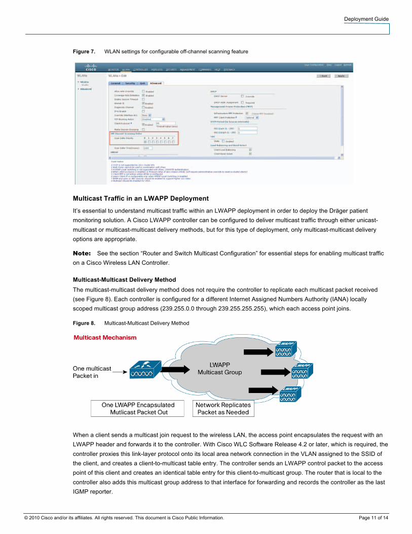
Off-channel scanning can also be configured from the Cisco Wireless LAN Controller GUI, as shown in Figure 7.
Deployment Guide
© 2010 Cisco and/or its affiliates. All rights reserved. This document is Cisco Public Information. Page 11 of 14
Figure 7. WLAN settings for configurable off-channel scanning feature
Multicast Traffic in an LWAPP Deployment
It’s essential to understand multicast traffic within an LWAPP deployment in order to deploy the Dräger patient monitoring solution. A Cisco LWAPP controller can be configured to deliver multicast traffic through either unicast-multicast or multicast-multicast delivery methods, but for this type of deployment, only multicast-multicast delivery options are appropriate.
Note: See the section “Router and Switch Multicast Configuration” for essential steps for enabling multicast traffic on a Cisco Wireless LAN Controller.
Multicast-Multicast Delivery Method The multicast-multicast delivery method does not require the controller to replicate each multicast packet received (see Figure 8). Each controller is configured for a different Internet Assigned Numbers Authority (IANA) locally scoped multicast group address (239.255.0.0 through 239.255.255.255), which each access point joins.
Figure 8. Multicast-Multicast Delivery Method
When a client sends a multicast join request to the wireless LAN, the access point encapsulates the request with an LWAPP header and forwards it to the controller. With Cisco WLC Software Release 4.2 or later, which is required, the controller proxies this link-layer protocol onto its local area network connection in the VLAN assigned to the SSID of the client, and creates a client-to-multicast table entry. The controller sends an LWAPP control packet to the access point of this client and creates an identical table entry for this client-to-multicast group. The router that is local to the controller also adds this multicast group address to that interface for forwarding and records the controller as the last IGMP reporter.

Deployment Guide
© 2010 Cisco and/or its affiliates. All rights reserved. This document is Cisco Public Information. Page 12 of 14
When traffic comes through a client’s multicast group, it arrives on the controller VLAN interface. The controller, using its local table of clients-to-multicast groups, sees that it has at least one listener still associated to one of its access points. It encapsulates this multicast packet with an LWAPP header and addresses it to the controller’s configured multicast group, which includes the WLAN/SSID. Each access point receives this multicast. If the controller finds a recipient in its local client-to-multicast group table, it removes the LWAPP header and broadcasts the multicast packet using the WLAN/SSID broadcast key.
Router and Switch Multicast Configuration
This section outlines some basic information for enabling multicast within your network environment. This information is intended only as a starting point for complete implementation planning and deployment.
Note: For some good background information on multicast routing, refer to the “Configuring IP Multicast Routing” section of the Cisco IOS IP Configuration Guide, Release 12.2, at: http://www.cisco.com/en/US/docs/ios/12_2/ip/configuration/guide/1cfmulti.html.
IGMP v2 Required for Wired Clients
The Cisco Wireless LAN Controller acts as an IGMP proxy, sending out IGMP membership reports on its behalf. The controller supports IGMP v1, IGMP v2, and IGMP v3 reports from wireless clients. However, the controller itself generates only IGMP v2 reports on the wired network. If the IGMP querier (such as a Cisco Catalyst® 6000 Series Switch) uses IGMP v1, it drops the IGMP v2 membership reports from the controller, and the devices will not go online because they never become members of their required multicast groups. Therefore, it is critical that the querier be configured to use IGMP v2.
Enabling IP Multicast Routing
An essential step in the correct deployment of Dräger medical devices in a Cisco network is to enable multicast routing.
The following global configuration command-line interface (CLI) command is required to allow multicast to function in any multicast-enabled network:
Router(config)# ip multicast-routing
This command should be entered to enable multicast routing on all routers within your network between the wireless LAN controller(s) and their respective access points. This allows the Cisco IOS® Software to forward multicast packets.
Note: For more information on entering CLI commands on a Cisco wireless LAN controller, refer to your controller configuration guide and command reference guide.
Enabling PIM on an Interface
Protocol-Independent Multicast (PIM) mode enables the routing interface for IGMP operation. The PIM mode determines how the router will populate its multicast routing table.
The following interface configuration CLI command is an example of a PIM mode configuration:
Router(config-if)# ip pim sparse-dense-mode
This method of enabling PIM in sparse-dense mode is the most inclusive option in a multicast environment, because the command does not require the router to know the multicast group rendezvous point (RP). There are other PIM options, but the Layer 3 interface directly connected to your controller must be PIM-enabled for multicast to function.

Deployment Guide
© 2010 Cisco and/or its affiliates. All rights reserved. This document is Cisco Public Information. Page 13 of 14
Note: All interfaces between your wireless LAN controller(s) and their respective access points must be enabled when you use multicast routing.
Caution: Do not disable IGMP snooping in a Dräger deployment, as this will cause excessive packet flooding. Disabling IGMP snooping greatly reduces the number of wireless patient monitors you can have on your network, and may still result in packet loss.
Multicast Enhancements of the Cisco Wireless LAN Controller
The following Cisco Wireless LAN Controller software releases contain important enhancements to multicast network environments.
Software Release 4.2 The latest update to multicast on the Cisco Wireless LAN Controller was the introduction of IGMP snooping capabilities. Starting with Software Release 4.2, the controller recognizes IGMP packets, allowing multicast packet forwarding and pruning for enhanced performance. By recognizing IGMP packets, the controller can forward multicast traffic to clients that are associated to SSIDs configured with the Access Points Groups feature. Prior to Software Release 4.2, multicast streams were flooded to all access points, and the resulting bandwidth congestion did not allow the Dräger monitors to communicate reliably. Wireless LAN Controller Software Release 4.2 helps to ensure that multicast traffic is delivered only to access points within each group.
Note: For more information on IGMP snooping, refer to your controller configuration guide and the Release Notes for Cisco Wireless LAN Controllers and Lightweight Access Points for Release 4.2.61.0 at: http://www.cisco.com/en/US/docs/wireless/controller/release/notes/crn4200.html
Infrastructure Planning for Infinity M300
The Infinity M300 uses a basic client-server architecture. In order to be able to use M300 in patient care, the device must be preconfigured for wireless operation during installation. Whenever clinical staff need to admit a patient who will be monitored using the M300, they will initiate a communication from the Infinity Central Station that will allow patient-specific settings to be transferred to the device. If the device is not charged, is out of the coverage range, or is not configured with the proper IP and encryption settings, the transfer of the patient-specific settings will fail.
For M300 deployment, no IP Multicast settings are required. In fact, all broadcast and multicast traffic sent to the device may cause it to wake up from its power-save mode, resulting in reduced battery life. Thus, Dräger requires hospitals to dedicate one SSID to all Infinity M300 devices
As to the design and coverage of the Wi-Fi network, IT departments need to consider that this is a medical device used 24 hours a day on patients. Careful planning of the Wi-Fi network, as well as notice to the clinical staff about planned maintenance schedules (for example, software upgrades to the wireless controller), are important tasks and can have a positive impact to the overall performance.

Deployment Guide
© 2010 Cisco and/or its affiliates. All rights reserved. This document is Cisco Public Information. Page 14 of 14
Printed in USA C07-588016-00 03/10


![[1 2013]Hack Pass Wifi(WEP WPA WPA2)](https://img.pdfslide.us/doc/110x75/55cf9451550346f57ba12e6c/1-2013hack-pass-wifiwep-wpa-wpa2-56195ec7c9bb5.jpg)