Embed Size (px)
Citation preview
August 20, 2007 22:50
Proceedings of ASME-IMECE’072007 ASME International Mechanical Engineering Congress and RD&D Expo
November 11-15, 2007, Seattle, Washington USA
IMECE2007-42559
HIGH SPEED ROTARY PULSE WIDTH MODULATED ON/OFF VALVE ∗
Haink C. Tu, Michael B. Rannow, James D. Van de Ven, Meng Wang, Perry Y. Li†and Thomas R. ChaseCenter for Compact and Efficient Fluid Power
Department of Mechanical EngineeringUniversity of Minnesota
111 Church St. SEMinneapolis, MN 55455
Email: {tuxxx021,rann0018,vandeven,wang134,pli,trchase}@me.umn.edu
ABSTRACT
A key enabling technology to effective on/off valve basedcontrol of hydraulic systems is the high speed on/off valve.Highspeed valves improve system efficiency for a given PWM fre-quency, offer faster control bandwidth, and produce smaller out-put pressure ripples. Current valves rely on the linear translationof a spool or poppet to meter flow. The valve spool must re-verse direction twice per PWM cycle. This constant accelerationand deceleration of the spool requires a power input proportionalto the PWM frequency cubed. As a result, current linear valvesare severely limited in their switching frequencies. In this paper,we present a novel fluid driven PWM on/off valve design that isbased on a unidirectional rotary spool. The spool is rotatedbycapturing momentum from the fluid flow through the valve. Theon/off functionality of our design is achieved via helical barri-ers that protrude from the surface of a cylindrical spool. Asthespool rotates, the helical barriers selectively channel the flow tothe application (on) or to tank (off). The duty ratio is controlledby altering the axial position of the spool. Since the spool nolonger accelerates or decelerates during operation, the power in-put to drive the valve must only compensate for viscous friction,which is proportional to the PWM frequency squared. We predictthat our current design, sized for a nominal flow rate of 40l/m,can achieve a PWM frequency of 84Hz. This paper presents ourvalve concept, design equations, and an analysis of predicted per-formance. A simulation of our design is also presented.
1 Introduction
On/off (or digital) valve based control of hydraulic systemsis an energy efficient alternative to control via throttlingvalves.In either the on or the off state, energy loss is minimized sinceeither the pressure drop across the valve is small or the flowthrough it is zero. When the on/off valve is pulse width modu-lated (PWM), the average pressure or flow can be controlled. Ourprevious papers [6] and [5] have proposed and modeled the useofa PWM on/off valve with a fixed displacement pump and an ac-cumulator to achieve the functionality of a variable displacementpump. A critical requirement for practical on/off valve basedcontrol is the availability of high speed on/off valves. High speedvalves improve system efficiency for a given PWM frequency,increase control bandwidth, and reduce output pressure ripple.Commercial on/off valves typically have transition times on theorder of 20msfor flow rates of 5l/m-40l/m. Digital valve con-trol with current valves demonstrates a noticeable decrease insystem efficiency when operating at PWM frequencies greaterthan 10Hz [5]. A limitation in conventional valve designs basedon linear spool or poppet movement is that the spool/poppet mustbe started and stopped during each on/off cycle. The power re-quired to actuate the valve is proportional to the 3rd power of thePWM frequency. In this paper, we present a novel fluid drivenunidirectional rotary PWM on/off valve design. Our valve spoolachieves rotary motion by capturing momentum from the fluidthat it meters. Since the spool rotates at a near constant veloc-ity, the power required to drive the valve only needs to overcomeviscous friction, which is proportional to the frequency squared.
1 Copyright c© 2007 by ASME
On/off valves have traditionally suffered from the trade offbetween switching speed and flow rate/pressure drop. Linearde-signs in particular are subject to this constraint due to thein-creased size and mass of the spool/poppet needed to handle largerflow rates. Typical high speed linear valve designs utilize piezo-electric materials or high speed solenoids for spool/poppet actua-tion, with a second pressure actuated stage if higher flow rates arerequired. Yokota et al. [7] presented a design in 1991 that usedtwo multilayered piezoelectric actuators in a push-pull type con-figuration to actuate a poppet, achieving switching times ontheorder of.1ms. While this switching time is impressive, the valveexhibited a pressure drop of 10×106Pa for a flow rate of 7.2l/m.Yokota et al. also proposed the use of this piezoelectric valve asa pilot stage to a secondary spool valve, however no informationwas given to the performance of this design. In 1994, Kajimaet al. presented a high speed solenoid valve design capable ofa switching time of 1ms [8]. In 2002, Lu et al. [9] presented asingle stage 3-way piezoelectric hydraulic poppet valve capableof flow rates of 8l/m with on/off times on the order of 1.5ms,while in 2004, Shi et al. [10] achieved an on/off time on the or-der of 1.5ms for a flow rate of 1.24l/m using a rare-earth-alloygiant magnetostrictive actuator to drive a linear valve spool. Thismagnetostrictive valve was then coupled with a second stageballvalve to achieve a two stage design capable of 8−10mson/offtimes for a flow rate of 120l/m [11]. On/off valves that featurea rotary spool typically improve upon this trade off. Since lessenergy is required to actuate a rotary design for high switchingspeeds, the valve spool can be made larger, thus enabling higherflow rates at lower pressure drops. Cui et al. [14], in 1991, intro-duced the concept of a coupled rotary two stage hydraulic valve.The first stage of the valve consisted of a bidirectional rotaryspool which generated pressure forces to move the spool axially.The axial motion of the spool opened and closed a second stagepoppet which was integrated onto the end of the spool. This de-sign was capable of achieving on/off times of 2.5mswith a nom-inal flow rate of 18l/m. In 1993, Royston et al. [13] proposed arotary pneumatic PWM on/off valve. The design utilized a unidi-rectional inner shaft driven by a DC motor to generate the on/offpulses with a bidirectional outer rotor to actuate the duty ratio ofthe valve. This valve was capable of PWM frequencies around80Hz. In 1980, Cyphelly et al. [12] proposed an externally actu-ated unidirectional 2-way hydraulic rotary spool valve that fea-tured a helical profile on the spool surface. Our design utilizes asimilar geometry, however our spool incorporates a 3-way designwith integrated turbines that capture momentum from the fluidflow to spin the valve spool. By harvesting momentum from themetered fluid to spin the spool, we can eliminate the complexcoupling of a mechanically actuated design. Additionally,thetrade off between switching speed and flow rate is greatly re-duced: as the flow rate through the valve is increased, inherentlymore momentum is available to spin the spool, although the sizeof the spool must be increased, increasing viscous friction.
Figure 1. Diagram of 3-way rotary spool
Figure 2. Diagram of internal geometry
This paper presents the concept and design of a unidirec-tional fluid driven rotary on/off valve. Section 2 introduces thefunctionality and design features of our concept. Section 3pro-vides an analysis of our design including calculations for perfor-mance and efficiency. A complete system simulation is presentedin Section 4, and some concluding remarks are discussed in Sec-tion 5.
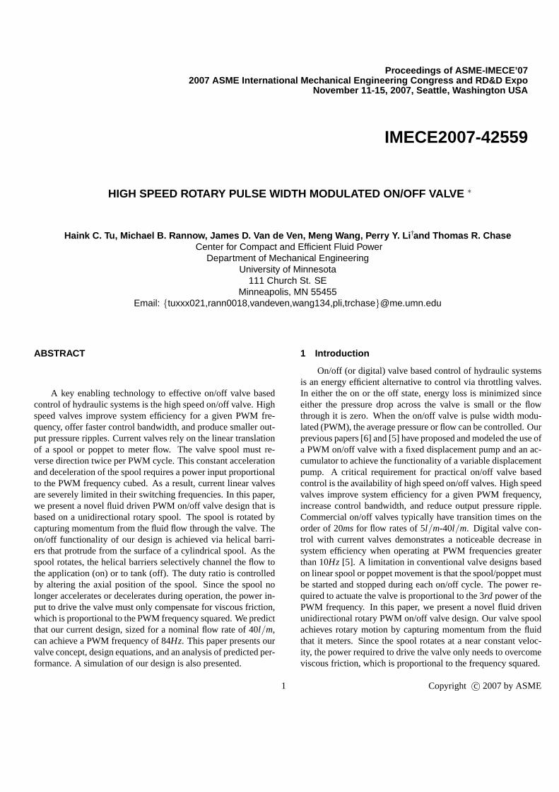
2 Self-spinning, 3-way Rotary on/off Valve ConceptOur self-spinning, 3-way rotary on/off valve concept is pre-
sented in Fig. 1. The valve spool consists of a central PWMsection sandwiched by two outlet turbines. The central section
2 Copyright c© 2007 by ASME
contains alternating helical barriers overlayed onto the spool sur-face. The helical barriers partition the spool into regionswhereflow is directed to the application (on, red) or to tank (off, blue).As the spool rotates, the inlet nozzles, which are stationary on thevalve sleeve, transition across the barriers and alternatethe flowpath between application and tank. The duty ratio, or propor-tion per PWM cycle that the flow is directed to the application,iscontrolled by changing the axial position of the spool. By trans-lating the spool upward relative to the inlet, the inlet willremainconnected to the tank region for a greater portion per rotation ofthe spool. This decreases the duty ratio. The opposite effect willoccur if the spool is translated downwards relative to the inlet.
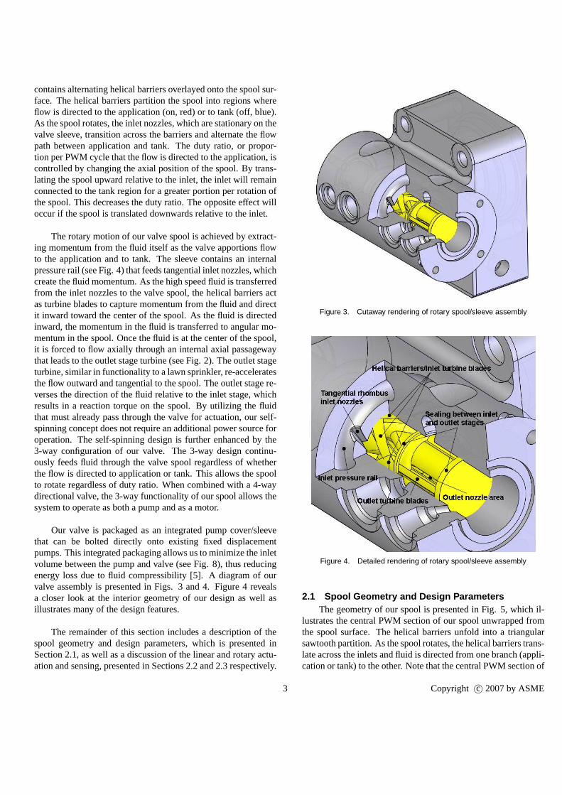
The rotary motion of our valve spool is achieved by extract-ing momentum from the fluid itself as the valve apportions flowto the application and to tank. The sleeve contains an internalpressure rail (see Fig. 4) that feeds tangential inlet nozzles, whichcreate the fluid momentum. As the high speed fluid is transferredfrom the inlet nozzles to the valve spool, the helical barriers actas turbine blades to capture momentum from the fluid and directit inward toward the center of the spool. As the fluid is directedinward, the momentum in the fluid is transferred to angular mo-mentum in the spool. Once the fluid is at the center of the spool,it is forced to flow axially through an internal axial passagewaythat leads to the outlet stage turbine (see Fig. 2). The outlet stageturbine, similar in functionality to a lawn sprinkler, re-acceleratesthe flow outward and tangential to the spool. The outlet stagere-verses the direction of the fluid relative to the inlet stage,whichresults in a reaction torque on the spool. By utilizing the fluidthat must already pass through the valve for actuation, our self-spinning concept does not require an additional power source foroperation. The self-spinning design is further enhanced bythe3-way configuration of our valve. The 3-way design continu-ously feeds fluid through the valve spool regardless of whetherthe flow is directed to application or tank. This allows the spoolto rotate regardless of duty ratio. When combined with a 4-waydirectional valve, the 3-way functionality of our spool allows thesystem to operate as both a pump and as a motor.
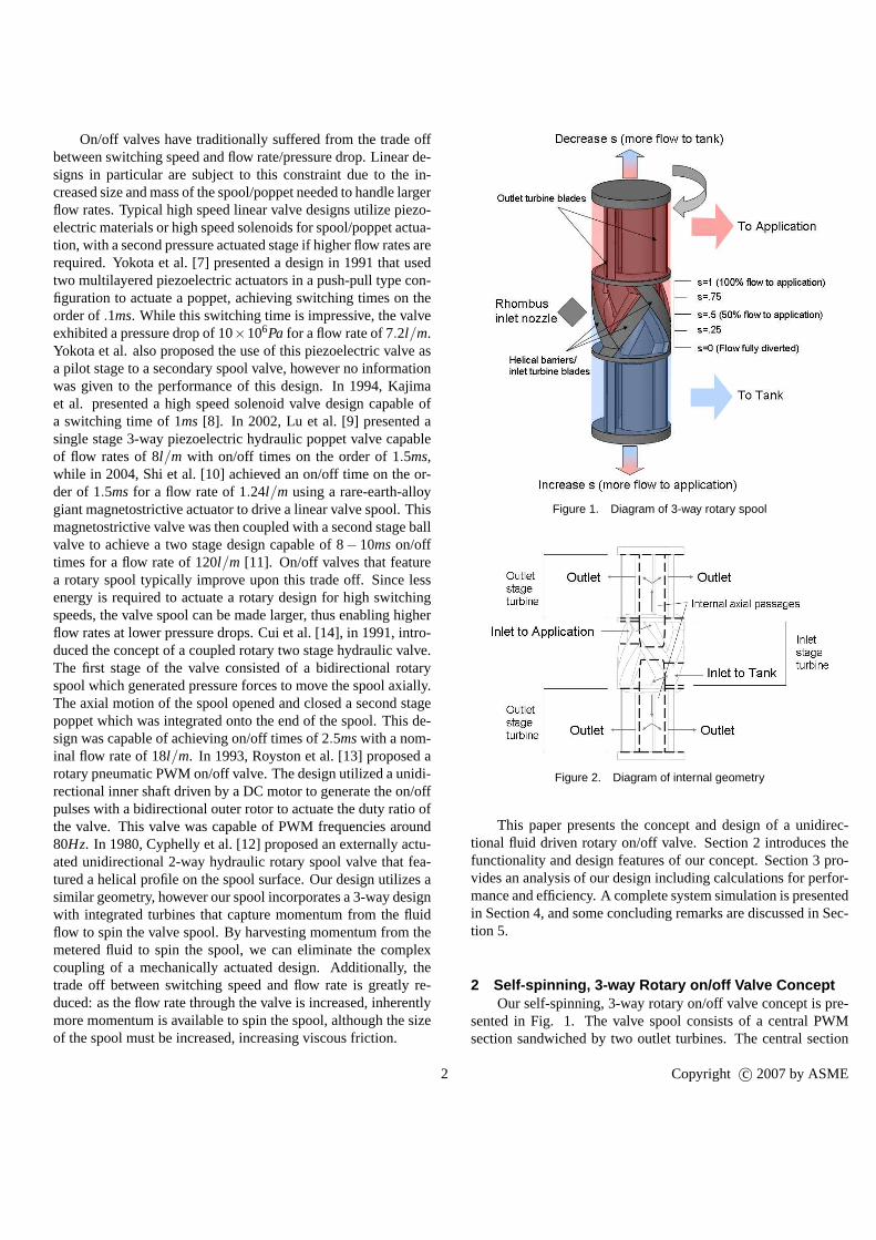
Our valve is packaged as an integrated pump cover/sleevethat can be bolted directly onto existing fixed displacementpumps. This integrated packaging allows us to minimize the inletvolume between the pump and valve (see Fig. 8), thus reducingenergy loss due to fluid compressibility [5]. A diagram of ourvalve assembly is presented in Figs. 3 and 4. Figure 4 revealsa closer look at the interior geometry of our design as well asillustrates many of the design features.
The remainder of this section includes a description of thespool geometry and design parameters, which is presented inSection 2.1, as well as a discussion of the linear and rotary actu-ation and sensing, presented in Sections 2.2 and 2.3 respectively.
Figure 3. Cutaway rendering of rotary spool/sleeve assembly
Figure 4. Detailed rendering of rotary spool/sleeve assembly
2.1 Spool Geometry and Design ParametersThe geometry of our spool is presented in Fig. 5, which il-
lustrates the central PWM section of our spool unwrapped fromthe spool surface. The helical barriers unfold into a triangularsawtooth partition. As the spool rotates, the helical barriers trans-late across the inlets and fluid is directed from one branch (appli-cation or tank) to the other. Note that the central PWM sectionof
3 Copyright c© 2007 by ASME
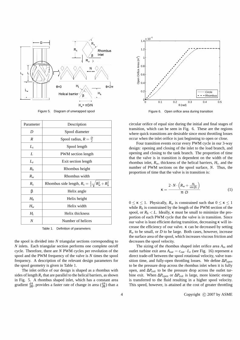
Figure 5. Diagram of unwrapped spool
Parameter Description
D Spool diameter
R Spool radius,R= D2
Ls Spool length
L PWM section length
Le Exit section length
Rh Rhombus height
Rw Rhombus width
Rs Rhombus side length,Rs = 12
√
R2w +R2
h
β Helix angle
Hh Helix height
Hw Helix width
Ht Helix thickness
N Number of helices
Table 1. Definition of parameters
the spool is divided intoN triangular sections corresponding toN inlets. Each triangular section performs one complete on/offcycle. Therefore, there areN PWM cycles per revolution of thespool and the PWM frequency of the valve isN times the spoolfrequency. A description of the relevant design parametersforthe spool geometry is given in Table 1.
The inlet orifice of our design is shaped as a rhombus withsides of lengthRs that are parallel to the helical barriers, as shownin Fig. 5. A rhombus shaped inlet, which has a constant areagradientdA
dθ , provides a faster rate of change in area (dAdθ ) than a
0 0.1 0.2 0.3 0.4 0.50
0.2
0.4
0.6
0.8
1
1.2
1.4x 10
−5
θ (rad)
Ope
n O
rific
e A
rea
(m2 )
CircleRhombus
Figure 6. Open orifice area during transition
circular orifice of equal size during the initial and final stages oftransition, which can be seen in Fig. 6. These are the regionswhere quick transitions are desirable since most throttling lossesoccur when the inlet orifice is just beginning to open or close.
Four transition events occur every PWM cycle in our 3-waydesign: opening and closing of the inlet to the load branch, andopening and closing to the tank branch. The proportion of timethat the valve is in transition is dependent on the width of therhombus inlet,Rw, thickness of the helical barriers,Ht , and thenumber of PWM sections on the spool surface,N. Thus, theproportion of time that the valve is in transition is:
κ =2·N ·
(
Rw + Htsin(β)
)
π ·D(1)
0 ≤ κ ≤ 1. Physically,Rw is constrained such that 0≤ κ ≤ 1while Rh is constrained by the length of the PWM section of thespool, orRh < L. Ideally, κ must be small to minimize the pro-portion of each PWM cycle that the valve is in transition. Sinceour valve is least efficient during transition, decreasingκ will in-crease the efficiency of our valve.κ can be decreased by settingRw to be small, orD to be large. Both cases, however, increasethe surface area of the spool, which increases viscous friction anddecreases the spool velocity.
The sizing of the rhombus shaped inlet orifice areaAin andoutlet turbine exit areaAout = cout ·Le (see Fig. 16) represent adirect trade-off between the spool rotational velocity, valve tran-sition time, and fully-open throttling losses. We define∆Popen
to be the pressure drop across the rhombus inlet when it is fullyopen, and∆Pexit to be the pressure drop across the outlet tur-bine exit. When∆Popen or ∆Pexit is large, more kinetic energyis transferred to the fluid resulting in a higher spool velocity.This speed, however, is attained at the cost of greater throttling
4 Copyright c© 2007 by ASME
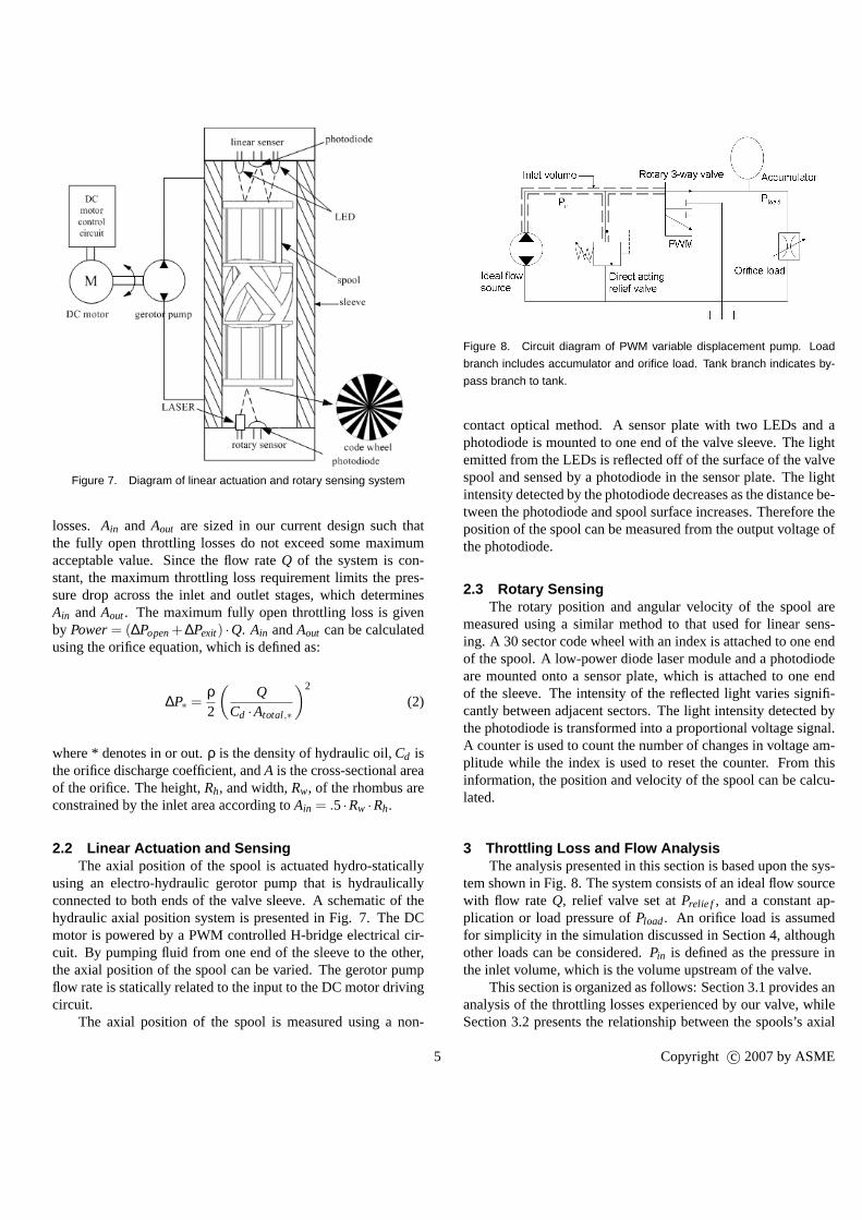
Figure 7. Diagram of linear actuation and rotary sensing system
losses. Ain and Aout are sized in our current design such thatthe fully open throttling losses do not exceed some maximumacceptable value. Since the flow rateQ of the system is con-stant, the maximum throttling loss requirement limits the pres-sure drop across the inlet and outlet stages, which determinesAin andAout. The maximum fully open throttling loss is givenby Power= (∆Popen+∆Pexit) ·Q. Ain andAout can be calculatedusing the orifice equation, which is defined as:
∆P∗ =ρ2
(
QCd ·Atotal,∗
)2
(2)
where * denotes in or out.ρ is the density of hydraulic oil,Cd isthe orifice discharge coefficient, andA is the cross-sectional areaof the orifice. The height,Rh, and width,Rw, of the rhombus areconstrained by the inlet area according toAin = .5·Rw ·Rh.
2.2 Linear Actuation and SensingThe axial position of the spool is actuated hydro-statically
using an electro-hydraulic gerotor pump that is hydraulicallyconnected to both ends of the valve sleeve. A schematic of thehydraulic axial position system is presented in Fig. 7. The DCmotor is powered by a PWM controlled H-bridge electrical cir-cuit. By pumping fluid from one end of the sleeve to the other,the axial position of the spool can be varied. The gerotor pumpflow rate is statically related to the input to the DC motor drivingcircuit.
The axial position of the spool is measured using a non-
Figure 8. Circuit diagram of PWM variable displacement pump. Load
branch includes accumulator and orifice load. Tank branch indicates by-
pass branch to tank.
contact optical method. A sensor plate with two LEDs and aphotodiode is mounted to one end of the valve sleeve. The lightemitted from the LEDs is reflected off of the surface of the valvespool and sensed by a photodiode in the sensor plate. The lightintensity detected by the photodiode decreases as the distance be-tween the photodiode and spool surface increases. Therefore theposition of the spool can be measured from the output voltageofthe photodiode.
2.3 Rotary SensingThe rotary position and angular velocity of the spool are
measured using a similar method to that used for linear sens-ing. A 30 sector code wheel with an index is attached to one endof the spool. A low-power diode laser module and a photodiodeare mounted onto a sensor plate, which is attached to one endof the sleeve. The intensity of the reflected light varies signifi-cantly between adjacent sectors. The light intensity detected bythe photodiode is transformed into a proportional voltage signal.A counter is used to count the number of changes in voltage am-plitude while the index is used to reset the counter. From thisinformation, the position and velocity of the spool can be calcu-lated.
3 Throttling Loss and Flow AnalysisThe analysis presented in this section is based upon the sys-
tem shown in Fig. 8. The system consists of an ideal flow sourcewith flow rate Q, relief valve set atPrelie f , and a constant ap-plication or load pressure ofPload. An orifice load is assumedfor simplicity in the simulation discussed in Section 4, althoughother loads can be considered.Pin is defined as the pressure inthe inlet volume, which is the volume upstream of the valve.
This section is organized as follows: Section 3.1 provides ananalysis of the throttling losses experienced by our valve,whileSection 3.2 presents the relationship between the spools’saxial
5 Copyright c© 2007 by ASME
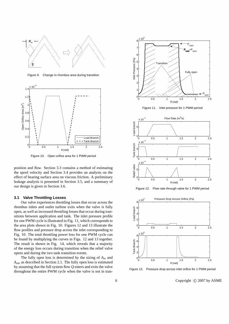
Figure 9. Change in rhombus area during transition
0 0.5 1 1.5 2 2.50
0.2
0.4
0.6
0.8
1
1.2
1.4x 10
−5
θ (rad)
Ope
n O
rific
e A
rea
(m2 )
Load BranchTank Branch
Figure 10. Open orifice area for 1 PWM period
position and flow. Section 3.3 contains a method of estimatingthe spool velocity and Section 3.4 provides an analysis on theeffect of bearing surface area on viscous friction. A preliminaryleakage analysis is presented in Section 3.5, and a summary ofour design is given in Section 3.6.
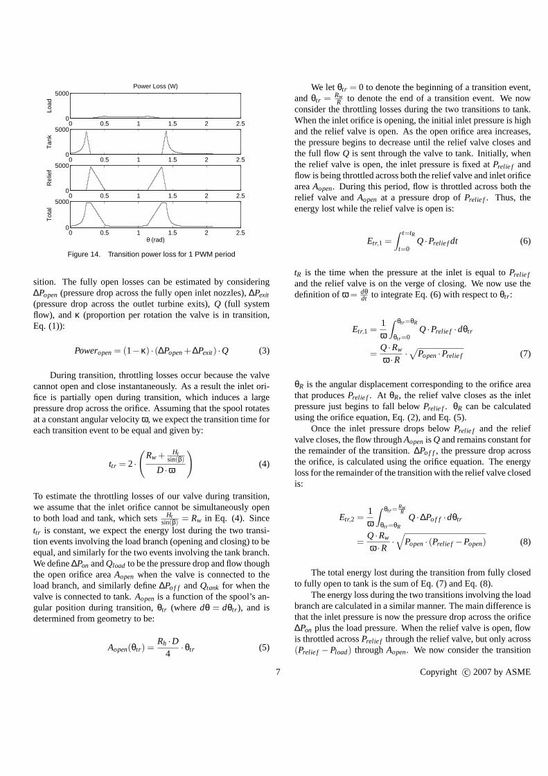
3.1 Valve Throttling LossesOur valve experiences throttling losses that occur across the
rhombus inlets and outlet turbine exits when the valve is fullyopen, as well as increased throttling losses that occur during tran-sitions between application and tank. The inlet pressure profilefor one PWM cycle is illustrated in Fig. 11, which correspondstothe area plots shown in Fig. 10. Figures 12 and 13 illustrate theflow profiles and pressure drop across the inlet corresponding toFig. 10. The total throttling power loss for one PWM cycle canbe found by multiplying the curves in Figs. 12 and 13 together.The result is shown in Fig. 14, which reveals that a majorityof the energy loss occurs during transition when the relief valveopens and during the two tank transition events.
The fully open loss is determined by the sizing ofAin andAout as described in Section 2.1. The fully open loss is estimatedby assuming that the full system flowQ enters and exits the valvethroughout the entire PWM cycle when the valve is not in tran-
0 0.5 1 1.5 2 2.50
1
2
3
4
5
6
7
8x 10
6
θ (rad)
Inle
t Pre
ssur
e (P
a)
Pload
Pload
Pload
+Popen
Prelief
Popen
Fully open
Transition
Figure 11. Inlet pressure for 1 PWM period
0 0.5 1 1.5 2 2.50
5
x 10−4
Load
bra
nch
Flow Rate (m3/s)
0 0.5 1 1.5 2 2.50
5
x 10−4
Tan
k br
anch
0 0.5 1 1.5 2 2.50
5
x 10−4
Rel
ief v
alve
θ (rad)
Figure 12. Flow rate through valve for 1 PWM period
0 0.5 1 1.5 2 2.50
2
4
6
8x 10
6
Load
bra
nch
Pressure Drop Across Orifice (Pa)
0 0.5 1 1.5 2 2.50
2
4
6
8x 10
6
Tan
k B
ranc
h
θ (rad)
Figure 13. Pressure drop across inlet orifice for 1 PWM period
6 Copyright c© 2007 by ASME
0 0.5 1 1.5 2 2.50
5000
Load
Power Loss (W)
0 0.5 1 1.5 2 2.50
5000
Tan
k
0 0.5 1 1.5 2 2.50
5000
Rel
ief
0 0.5 1 1.5 2 2.50
5000
Tot
al
θ (rad)
Figure 14. Transition power loss for 1 PWM period
sition. The fully open losses can be estimated by considering∆Popen (pressure drop across the fully open inlet nozzles),∆Pexit
(pressure drop across the outlet turbine exits),Q (full systemflow), andκ (proportion per rotation the valve is in transition,Eq. (1)):
Poweropen= (1−κ) · (∆Popen+∆Pexit) ·Q (3)
During transition, throttling losses occur because the valvecannot open and close instantaneously. As a result the inletori-fice is partially open during transition, which induces a largepressure drop across the orifice. Assuming that the spool rotatesat a constant angular velocityω, we expect the transition time foreach transition event to be equal and given by:
ttr = 2·
(
Rw + Htsin(β)
D ·ω
)
(4)
To estimate the throttling losses of our valve during transition,we assume that the inlet orifice cannot be simultaneously opento both load and tank, which setsHt
sin(β) = Rw in Eq. (4). Sincettr is constant, we expect the energy lost during the two transi-tion events involving the load branch (opening and closing)to beequal, and similarly for the two events involving the tank branch.We define∆Pon andQload to be the pressure drop and flow thoughthe open orifice areaAopen when the valve is connected to theload branch, and similarly define∆Po f f andQtank for when thevalve is connected to tank.Aopen is a function of the spool’s an-gular position during transition,θtr (wheredθ = dθtr ), and isdetermined from geometry to be:
Aopen(θtr) =Rh ·D
4·θtr (5)
We letθtr = 0 to denote the beginning of a transition event,andθtr = Rw
R to denote the end of a transition event. We nowconsider the throttling losses during the two transitions to tank.When the inlet orifice is opening, the initial inlet pressure is highand the relief valve is open. As the open orifice area increases,the pressure begins to decrease until the relief valve closes andthe full flow Q is sent through the valve to tank. Initially, whenthe relief valve is open, the inlet pressure is fixed atPrelie f andflow is being throttled across both the relief valve and inletorificeareaAopen. During this period, flow is throttled across both therelief valve andAopen at a pressure drop ofPrelie f . Thus, theenergy lost while the relief valve is open is:
Etr,1 =∫ t=tR
t=0Q·Prelie fdt (6)
tR is the time when the pressure at the inlet is equal toPrelie f
and the relief valve is on the verge of closing. We now use thedefinition ofω = dθ
dt to integrate Eq. (6) with respect toθtr :
Etr,1 =1ω
∫ θtr=θR
θtr=0Q·Prelie f ·dθtr
=Q·Rw
ω ·R·√
Popen·Prelie f (7)
θR is the angular displacement corresponding to the orifice areathat producesPrelie f . At θR, the relief valve closes as the inletpressure just begins to fall belowPrelie f . θR can be calculatedusing the orifice equation, Eq. (2), and Eq. (5).
Once the inlet pressure drops belowPrelie f and the reliefvalve closes, the flow throughAopenis Q and remains constant forthe remainder of the transition.∆Po f f , the pressure drop acrossthe orifice, is calculated using the orifice equation. The energyloss for the remainder of the transition with the relief valve closedis:
Etr,2 =1ω
∫ θtr=RwR
θtr=θR
Q·∆Po f f ·dθtr
=Q·Rw
ω ·R·√
Popen· (Prelie f −Popen) (8)
The total energy lost during the transition from fully closedto fully open to tank is the sum of Eq. (7) and Eq. (8).
The energy loss during the two transitions involving the loadbranch are calculated in a similar manner. The main difference isthat the inlet pressure is now the pressure drop across the orifice∆Pon plus the load pressure. When the relief valve is open, flowis throttled acrossPrelie f through the relief valve, but only across(Prelie f −Pload) throughAopen. We now consider the transition
7 Copyright c© 2007 by ASME
when the orifice is beginning to open to the load branch. The en-ergy lost during the initial stage of the transition when thereliefvalve is open is:
Etr,3 =1ω
∫ θtr=θR
θtr=0(Q−Qload) ·Prelie f ·dθtr
+1ω
∫ θtr=θR
θtr=0Qload · (Prelie f −Pload) ·dθtr
=Q·Rw
ω ·R·
√
Popen
(Prelie f −Pload)·
(
Prelie f −12
Pload
)
(9)
Once the relief valve closes, the remaining energy loss dur-ing the transition is:
Etr,4 =1ω
∫ θtr=RwR
θtr=θR
Q·Pon ·dθtr
=Q·Rw
ω ·R·
(
√
Popen· (Prelie f −Pload)−Popen
)
(10)
The total energy lost during the transition from fully closedto fully open to the load branch is the sum of Eq. (9) and Eq.(10). The total energy lost for all four transition events, or forone complete PWM cycle, is:
Etr,total = 2· (Etr,1 +Etr,2 +Etr,3 +Etr,4) (11)
The total power loss due to fully open and transition throt-tling is:
Powertotal = Poweropen+Etr,total ·N ·ω2·π
(12)
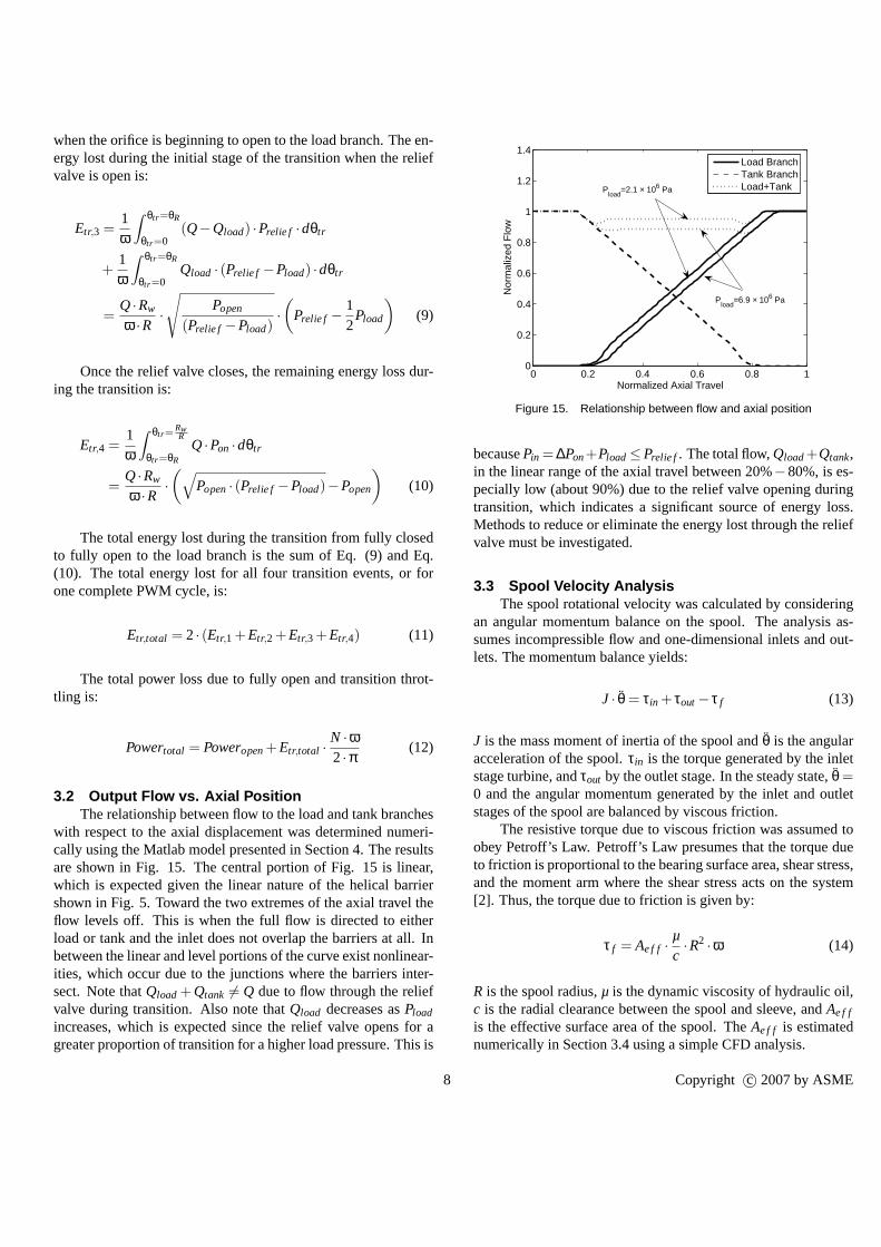
3.2 Output Flow vs. Axial PositionThe relationship between flow to the load and tank branches
with respect to the axial displacement was determined numeri-cally using the Matlab model presented in Section 4. The resultsare shown in Fig. 15. The central portion of Fig. 15 is linear,which is expected given the linear nature of the helical barriershown in Fig. 5. Toward the two extremes of the axial travel theflow levels off. This is when the full flow is directed to eitherload or tank and the inlet does not overlap the barriers at all. Inbetween the linear and level portions of the curve exist nonlinear-ities, which occur due to the junctions where the barriers inter-sect. Note thatQload + Qtank 6= Q due to flow through the reliefvalve during transition. Also note thatQload decreases asPload
increases, which is expected since the relief valve opens for agreater proportion of transition for a higher load pressure. This is
0 0.2 0.4 0.6 0.8 10
0.2
0.4
0.6
0.8
1
1.2
1.4
Normalized Axial Travel
Nor
mal
ized
Flo
w
Load BranchTank BranchLoad+Tank
Pload
=6.9 × 10⁶ Pa
Pload
=2.1 × 10⁶ Pa
Figure 15. Relationship between flow and axial position
becausePin = ∆Pon+Pload≤Prelie f . The total flow,Qload+Qtank,in the linear range of the axial travel between 20%−80%, is es-pecially low (about 90%) due to the relief valve opening duringtransition, which indicates a significant source of energy loss.Methods to reduce or eliminate the energy lost through the reliefvalve must be investigated.
3.3 Spool Velocity AnalysisThe spool rotational velocity was calculated by considering
an angular momentum balance on the spool. The analysis as-sumes incompressible flow and one-dimensional inlets and out-lets. The momentum balance yields:
J · θ = τin + τout− τ f (13)
J is the mass moment of inertia of the spool andθ is the angularacceleration of the spool.τin is the torque generated by the inletstage turbine, andτout by the outlet stage. In the steady state,θ =0 and the angular momentum generated by the inlet and outletstages of the spool are balanced by viscous friction.
The resistive torque due to viscous friction was assumed toobey Petroff’s Law. Petroff’s Law presumes that the torque dueto friction is proportional to the bearing surface area, shear stress,and the moment arm where the shear stress acts on the system[2]. Thus, the torque due to friction is given by:
τ f = Ae f f ·µc·R2 ·ω (14)
R is the spool radius,µ is the dynamic viscosity of hydraulic oil,c is the radial clearance between the spool and sleeve, andAe f f
is the effective surface area of the spool. TheAe f f is estimatednumerically in Section 3.4 using a simple CFD analysis.
8 Copyright c© 2007 by ASME
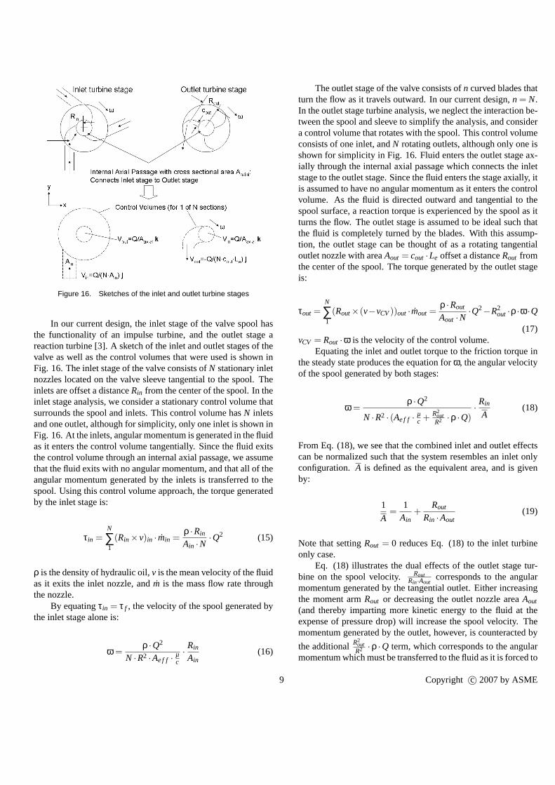
Figure 16. Sketches of the inlet and outlet turbine stages
In our current design, the inlet stage of the valve spool hasthe functionality of an impulse turbine, and the outlet stage areaction turbine [3]. A sketch of the inlet and outlet stagesof thevalve as well as the control volumes that were used is shown inFig. 16. The inlet stage of the valve consists ofN stationary inletnozzles located on the valve sleeve tangential to the spool.Theinlets are offset a distanceRin from the center of the spool. In theinlet stage analysis, we consider a stationary control volume thatsurrounds the spool and inlets. This control volume hasN inletsand one outlet, although for simplicity, only one inlet is shown inFig. 16. At the inlets, angular momentum is generated in the fluidas it enters the control volume tangentially. Since the fluidexitsthe control volume through an internal axial passage, we assumethat the fluid exits with no angular momentum, and that all of theangular momentum generated by the inlets is transferred to thespool. Using this control volume approach, the torque generatedby the inlet stage is:
τin =N
∑1
(Rin ×v)in · min =ρ ·Rin
Ain ·N·Q2 (15)
ρ is the density of hydraulic oil,v is the mean velocity of the fluidas it exits the inlet nozzle, and ˙m is the mass flow rate throughthe nozzle.
By equatingτin = τ f , the velocity of the spool generated bythe inlet stage alone is:
ω =ρ ·Q2
N ·R2 ·Ae f f ·µc
·Rin
Ain(16)
The outlet stage of the valve consists ofn curved blades thatturn the flow as it travels outward. In our current design,n = N.In the outlet stage turbine analysis, we neglect the interaction be-tween the spool and sleeve to simplify the analysis, and considera control volume that rotates with the spool. This control volumeconsists of one inlet, andN rotating outlets, although only one isshown for simplicity in Fig. 16. Fluid enters the outlet stage ax-ially through the internal axial passage which connects theinletstage to the outlet stage. Since the fluid enters the stage axially, itis assumed to have no angular momentum as it enters the controlvolume. As the fluid is directed outward and tangential to thespool surface, a reaction torque is experienced by the spoolas itturns the flow. The outlet stage is assumed to be ideal such thatthe fluid is completely turned by the blades. With this assump-tion, the outlet stage can be thought of as a rotating tangentialoutlet nozzle with areaAout = cout ·Le offset a distanceRout fromthe center of the spool. The torque generated by the outlet stageis:
τout =N
∑1
(Rout×(v−vCV))out ·mout =ρ ·Rout
Aout ·N·Q2−R2
out ·ρ ·ω ·Q
(17)vCV = Rout ·ω is the velocity of the control volume.
Equating the inlet and outlet torque to the friction torque inthe steady state produces the equation forω, the angular velocityof the spool generated by both stages:
ω =ρ ·Q2
N ·R2 · (Ae f f ·µc +
R2outR2 ·ρ ·Q)
·Rin
A(18)
From Eq. (18), we see that the combined inlet and outlet effectscan be normalized such that the system resembles an inlet onlyconfiguration.A is defined as the equivalent area, and is givenby:
1
A=
1Ain
+Rout
Rin ·Aout(19)
Note that settingRout = 0 reduces Eq. (18) to the inlet turbineonly case.
Eq. (18) illustrates the dual effects of the outlet stage tur-bine on the spool velocity. Rout
Rin·Aoutcorresponds to the angular
momentum generated by the tangential outlet. Either increasingthe moment armRout or decreasing the outlet nozzle areaAout
(and thereby imparting more kinetic energy to the fluid at theexpense of pressure drop) will increase the spool velocity.Themomentum generated by the outlet, however, is counteractedby
the additionalR2outR2 ·ρ ·Q term, which corresponds to the angular
momentum which must be transferred to the fluid as it is forcedto
9 Copyright c© 2007 by ASME
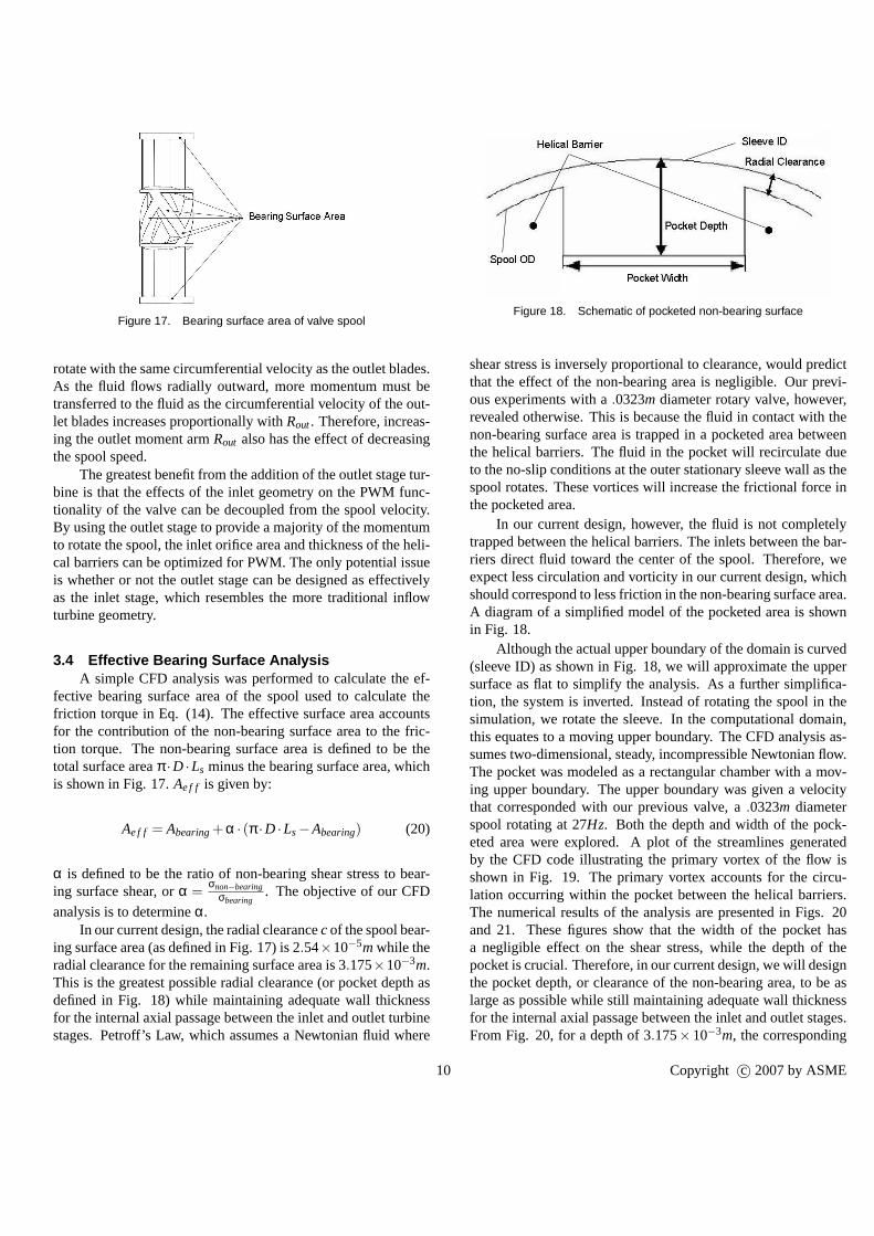
Figure 17. Bearing surface area of valve spool
rotate with the same circumferential velocity as the outletblades.As the fluid flows radially outward, more momentum must betransferred to the fluid as the circumferential velocity of the out-let blades increases proportionally withRout. Therefore, increas-ing the outlet moment armRout also has the effect of decreasingthe spool speed.
The greatest benefit from the addition of the outlet stage tur-bine is that the effects of the inlet geometry on the PWM func-tionality of the valve can be decoupled from the spool velocity.By using the outlet stage to provide a majority of the momentumto rotate the spool, the inlet orifice area and thickness of the heli-cal barriers can be optimized for PWM. The only potential issueis whether or not the outlet stage can be designed as effectivelyas the inlet stage, which resembles the more traditional inflowturbine geometry.
3.4 Effective Bearing Surface AnalysisA simple CFD analysis was performed to calculate the ef-
fective bearing surface area of the spool used to calculate thefriction torque in Eq. (14). The effective surface area accountsfor the contribution of the non-bearing surface area to the fric-tion torque. The non-bearing surface area is defined to be thetotal surface areaπ ·D ·Ls minus the bearing surface area, whichis shown in Fig. 17.Ae f f is given by:
Ae f f = Abearing+α · (π ·D ·Ls−Abearing) (20)
α is defined to be the ratio of non-bearing shear stress to bear-ing surface shear, orα =
σnon−bearingσbearing
. The objective of our CFD
analysis is to determineα.In our current design, the radial clearancecof the spool bear-
ing surface area (as defined in Fig. 17) is 2.54×10⁻⁵mwhile theradial clearance for the remaining surface area is 3.175×10⁻³m.This is the greatest possible radial clearance (or pocket depth asdefined in Fig. 18) while maintaining adequate wall thicknessfor the internal axial passage between the inlet and outlet turbinestages. Petroff’s Law, which assumes a Newtonian fluid where
Figure 18. Schematic of pocketed non-bearing surface
shear stress is inversely proportional to clearance, wouldpredictthat the effect of the non-bearing area is negligible. Our previ-ous experiments with a.0323m diameter rotary valve, however,revealed otherwise. This is because the fluid in contact withthenon-bearing surface area is trapped in a pocketed area betweenthe helical barriers. The fluid in the pocket will recirculate dueto the no-slip conditions at the outer stationary sleeve wall as thespool rotates. These vortices will increase the frictionalforce inthe pocketed area.
In our current design, however, the fluid is not completelytrapped between the helical barriers. The inlets between the bar-riers direct fluid toward the center of the spool. Therefore,weexpect less circulation and vorticity in our current design, whichshould correspond to less friction in the non-bearing surface area.A diagram of a simplified model of the pocketed area is shownin Fig. 18.
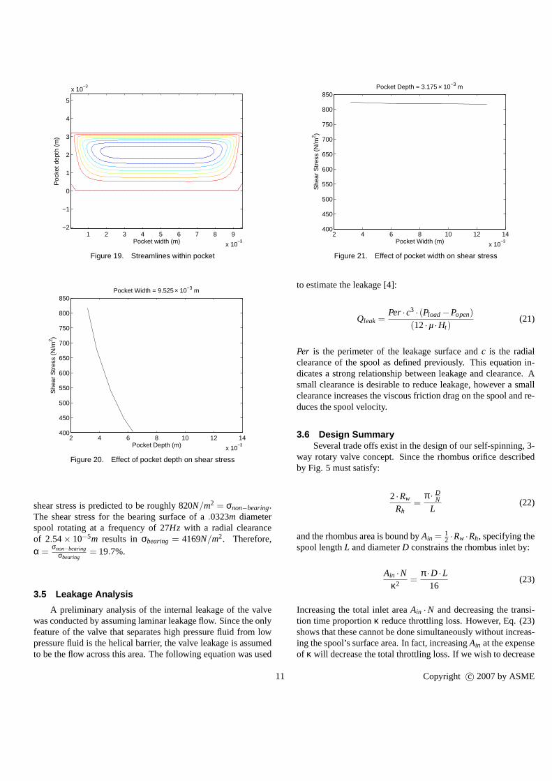
Although the actual upper boundary of the domain is curved(sleeve ID) as shown in Fig. 18, we will approximate the uppersurface as flat to simplify the analysis. As a further simplifica-tion, the system is inverted. Instead of rotating the spool in thesimulation, we rotate the sleeve. In the computational domain,this equates to a moving upper boundary. The CFD analysis as-sumes two-dimensional, steady, incompressible Newtonianflow.The pocket was modeled as a rectangular chamber with a mov-ing upper boundary. The upper boundary was given a velocitythat corresponded with our previous valve, a.0323m diameterspool rotating at 27Hz. Both the depth and width of the pock-eted area were explored. A plot of the streamlines generatedby the CFD code illustrating the primary vortex of the flow isshown in Fig. 19. The primary vortex accounts for the circu-lation occurring within the pocket between the helical barriers.The numerical results of the analysis are presented in Figs.20and 21. These figures show that the width of the pocket hasa negligible effect on the shear stress, while the depth of thepocket is crucial. Therefore, in our current design, we willdesignthe pocket depth, or clearance of the non-bearing area, to beaslarge as possible while still maintaining adequate wall thicknessfor the internal axial passage between the inlet and outlet stages.From Fig. 20, for a depth of 3.175×10⁻³m, the corresponding
10 Copyright c© 2007 by ASME
Pocket width (m)
Poc
ket d
epth
(m
)
1 2 3 4 5 6 7 8 9
x 10−3
−2
−1
0
1
2
3
4
5
x 10−3
Figure 19. Streamlines within pocket
2 4 6 8 10 12 14
x 10−3
400
450
500
550
600
650
700
750
800
850
Pocket Depth (m)
She
ar S
tres
s (N
/m2 )
Pocket Width = 9.525 × 10⁻³ m
Figure 20. Effect of pocket depth on shear stress
shear stress is predicted to be roughly 820N/m2 = σnon−bearing.The shear stress for the bearing surface of a.0323m diameterspool rotating at a frequency of 27Hz with a radial clearanceof 2.54× 10⁻⁵m results inσbearing = 4169N/m2. Therefore,α =
σnon−bearingσbearing
= 19.7%.
3.5 Leakage Analysis
A preliminary analysis of the internal leakage of the valvewas conducted by assuming laminar leakage flow. Since the onlyfeature of the valve that separates high pressure fluid from lowpressure fluid is the helical barrier, the valve leakage is assumedto be the flow across this area. The following equation was used
2 4 6 8 10 12 14
x 10−3
400
450
500
550
600
650
700
750
800
850
Pocket Width (m)
She
ar S
tres
s (N
/m2 )
Pocket Depth = 3.175 × 10⁻³ m
Figure 21. Effect of pocket width on shear stress
to estimate the leakage [4]:
Qleak =Per·c3 · (Pload−Popen)
(12·µ·Ht)(21)
Per is the perimeter of the leakage surface andc is the radialclearance of the spool as defined previously. This equation in-dicates a strong relationship between leakage and clearance. Asmall clearance is desirable to reduce leakage, however a smallclearance increases the viscous friction drag on the spool and re-duces the spool velocity.
3.6 Design SummarySeveral trade offs exist in the design of our self-spinning,3-
way rotary valve concept. Since the rhombus orifice describedby Fig. 5 must satisfy:
2·Rw
Rh=
π · DN
L(22)
and the rhombus area is bound byAin = 12 ·Rw ·Rh, specifying the
spool lengthL and diameterD constrains the rhombus inlet by:
Ain ·Nκ2 =
π ·D ·L16
(23)
Increasing the total inlet areaAin ·N and decreasing the transi-tion time proportionκ reduce throttling loss. However, Eq. (23)shows that these cannot be done simultaneously without increas-ing the spool’s surface area. In fact, increasingAin at the expenseof κ will decrease the total throttling loss. If we wish to decrease
11 Copyright c© 2007 by ASME
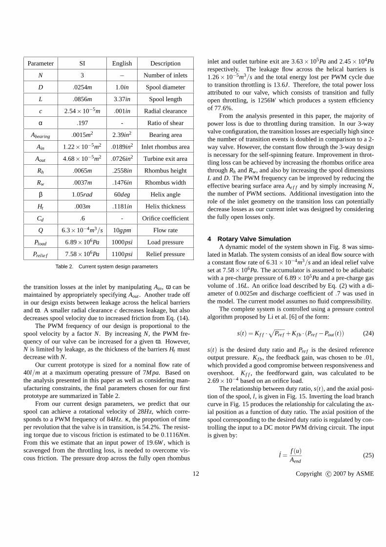
Parameter SI English Description
N 3 − Number of inlets
D .0254m 1.0in Spool diameter
L .0856m 3.37in Spool length
c 2.54×10⁻⁵m .001in Radial clearance
α .197 - Ratio of shear
Abearing .0015m2 2.39in2 Bearing area
Ain 1.22×10⁻⁵m2 .0189in2 Inlet rhombus area
Aout 4.68×10⁻⁵m2 .0726in2 Turbine exit area
Rh .0065m .2558in Rhombus height
Rw .0037m .1476in Rhombus width
β 1.05rad 60deg Helix angle
Ht .003m .1181in Helix thickness
Cd .6 - Orifice coefficient
Q 6.3×10⁻⁴m3/s 10gpm Flow rate
Pload 6.89×10⁶Pa 1000psi Load pressure
Prelie f 7.58×10⁶Pa 1100psi Relief pressure
Table 2. Current system design parameters
the transition losses at the inlet by manipulatingAin, ω can bemaintained by appropriately specifyingAout. Another trade offin our design exists between leakage across the helical barriersandω. A smaller radial clearancec decreases leakage, but alsodecreases spool velocity due to increased friction from Eq.(14).
The PWM frequency of our design is proportional to thespool velocity by a factorN. By increasingN, the PWM fre-quency of our valve can be increased for a givenω. However,N is limited by leakage, as the thickness of the barriersHt mustdecrease withN.
Our current prototype is sized for a nominal flow rate of40l/m at a maximum operating pressure of 7Mpa. Based onthe analysis presented in this paper as well as considering man-ufacturing constraints, the final parameters chosen for ourfirstprototype are summarized in Table 2.
From our current design parameters, we predict that ourspool can achieve a rotational velocity of 28Hz, which corre-sponds to a PWM frequency of 84Hz. κ, the proportion of timeper revolution that the valve is in transition, is 54.2%. The resist-ing torque due to viscous friction is estimated to be 0.1116Nm.From this we estimate that an input power of 19.6W, which isscavenged from the throttling loss, is needed to overcome vis-cous friction. The pressure drop across the fully open rhombus
inlet and outlet turbine exit are 3.63×10⁵Pa and 2.45×10⁴Parespectively. The leakage flow across the helical barriers is1.26× 10−5m3/s and the total energy lost per PWM cycle dueto transition throttling is 13.6J. Therefore, the total power lossattributed to our valve, which consists of transition and fullyopen throttling, is 1256W which produces a system efficiencyof 77.6%.
From the analysis presented in this paper, the majority ofpower loss is due to throttling during transition. In our 3-wayvalve configuration, the transition losses are especially high sincethe number of transition events is doubled in comparison to a2-way valve. However, the constant flow through the 3-way designis necessary for the self-spinning feature. Improvement inthrot-tling loss can be achieved by increasing the rhombus orifice areathroughRh andRw, and also by increasing the spool dimensionsL andD. The PWM frequency can be improved by reducing theeffective bearing surface areaAe f f and by simply increasingN,the number of PWM sections. Additional investigation into therole of the inlet geometry on the transition loss can potentiallydecrease losses as our current inlet was designed by consideringthe fully open losses only.
4 Rotary Valve SimulationA dynamic model of the system shown in Fig. 8 was simu-
lated in Matlab. The system consists of an ideal flow source witha constant flow rate of 6.31×10⁻⁴m3/sand an ideal relief valveset at 7.58×10⁶Pa. The accumulator is assumed to be adiabaticwith a pre-charge pressure of 6.89×10⁵Pa and a pre-charge gasvolume of.16L. An orifice load described by Eq. (2) with a di-ameter of 0.0025m and discharge coefficient of.7 was used inthe model. The current model assumes no fluid compressibility.
The complete system is controlled using a pressure controlalgorithm proposed by Li et al. [6] of the form:
s(t) = K f f ·√
Pre f +K f b · (Pre f −Pout(t)) (24)
s(t) is the desired duty ratio andPre f is the desired referenceoutput pressure.K f b, the feedback gain, was chosen to be.01,which provided a good compromise between responsiveness andovershoot. K f f , the feedforward gain, was calculated to be2.69×10−4 based on an orifice load.
The relationship between duty ratio,s(t), and the axial posi-tion of the spool,l , is given in Fig. 15. Inverting the load branchcurve in Fig. 15 produces the relationship for calculating the ax-ial position as a function of duty ratio. The axial position of thespool corresponding to the desired duty ratio is regulated by con-trolling the input to a DC motor PWM driving circuit. The inputis given by:
l =f (u)
Aend(25)
12 Copyright c© 2007 by ASME
0 0.5 1 1.5 2 2.5 30
1
2
3
4
5
6
7x 10
6
Time (s)
Pre
ssur
e (P
a)
ReferenceOutput
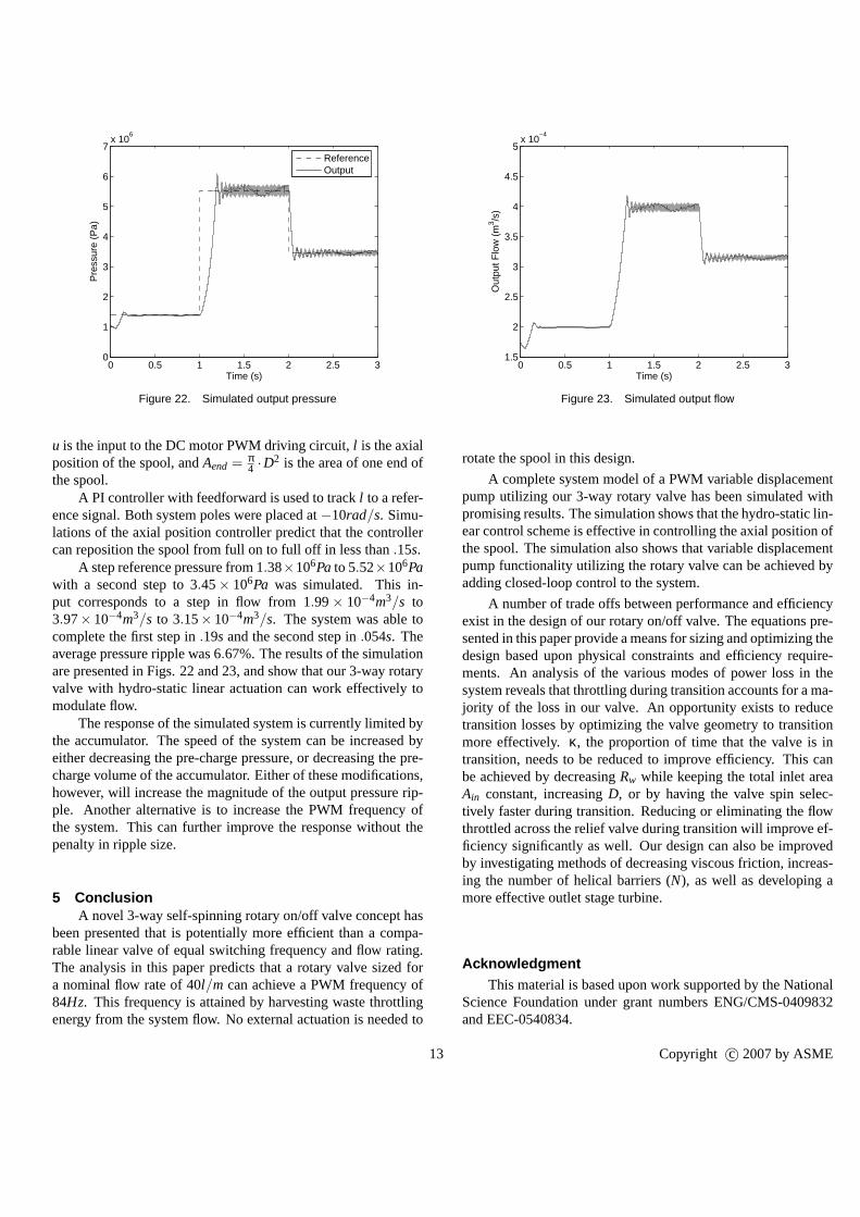
Figure 22. Simulated output pressure
u is the input to the DC motor PWM driving circuit,l is the axialposition of the spool, andAend = π
4 ·D2 is the area of one end of
the spool.A PI controller with feedforward is used to trackl to a refer-
ence signal. Both system poles were placed at−10rad/s. Simu-lations of the axial position controller predict that the controllercan reposition the spool from full on to full off in less than.15s.
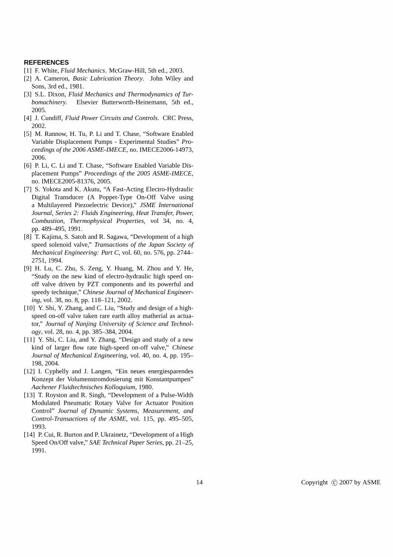
A step reference pressure from 1.38×10⁶Pa to 5.52×10⁶Pawith a second step to 3.45× 10⁶Pa was simulated. This in-put corresponds to a step in flow from 1.99× 10⁻⁴m3/s to3.97× 10−4m3/s to 3.15× 10⁻⁴m3/s. The system was able tocomplete the first step in.19s and the second step in.054s. Theaverage pressure ripple was 6.67%. The results of the simulationare presented in Figs. 22 and 23, and show that our 3-way rotaryvalve with hydro-static linear actuation can work effectively tomodulate flow.
The response of the simulated system is currently limited bythe accumulator. The speed of the system can be increased byeither decreasing the pre-charge pressure, or decreasing the pre-charge volume of the accumulator. Either of these modifications,however, will increase the magnitude of the output pressurerip-ple. Another alternative is to increase the PWM frequency ofthe system. This can further improve the response without thepenalty in ripple size.
5 ConclusionA novel 3-way self-spinning rotary on/off valve concept has
been presented that is potentially more efficient than a compa-rable linear valve of equal switching frequency and flow rating.The analysis in this paper predicts that a rotary valve sizedfora nominal flow rate of 40l/m can achieve a PWM frequency of84Hz. This frequency is attained by harvesting waste throttlingenergy from the system flow. No external actuation is needed to
0 0.5 1 1.5 2 2.5 31.5
2
2.5
3
3.5
4
4.5
5x 10
−4
Time (s)
Out
put F
low
(m
3 /s)
Figure 23. Simulated output flow
rotate the spool in this design.
A complete system model of a PWM variable displacementpump utilizing our 3-way rotary valve has been simulated withpromising results. The simulation shows that the hydro-static lin-ear control scheme is effective in controlling the axial position ofthe spool. The simulation also shows that variable displacementpump functionality utilizing the rotary valve can be achieved byadding closed-loop control to the system.
A number of trade offs between performance and efficiencyexist in the design of our rotary on/off valve. The equationspre-sented in this paper provide a means for sizing and optimizing thedesign based upon physical constraints and efficiency require-ments. An analysis of the various modes of power loss in thesystem reveals that throttling during transition accountsfor a ma-jority of the loss in our valve. An opportunity exists to reducetransition losses by optimizing the valve geometry to transitionmore effectively. κ, the proportion of time that the valve is intransition, needs to be reduced to improve efficiency. This canbe achieved by decreasingRw while keeping the total inlet areaAin constant, increasingD, or by having the valve spin selec-tively faster during transition. Reducing or eliminating the flowthrottled across the relief valve during transition will improve ef-ficiency significantly as well. Our design can also be improvedby investigating methods of decreasing viscous friction, increas-ing the number of helical barriers (N), as well as developing amore effective outlet stage turbine.
AcknowledgmentThis material is based upon work supported by the National
Science Foundation under grant numbers ENG/CMS-0409832and EEC-0540834.
13 Copyright c© 2007 by ASME
REFERENCES[1] F. White,Fluid Mechanics. McGraw-Hill, 5th ed., 2003.[2] A. Cameron,Basic Lubrication Theory. John Wiley and
Sons, 3rd ed., 1981.[3] S.L. Dixon, Fluid Mechanics and Thermodynamics of Tur-
bomachinery. Elsevier Butterworth-Heinemann, 5th ed.,2005.
[4] J. Cundiff, Fluid Power Circuits and Controls. CRC Press,2002.
[5] M. Rannow, H. Tu, P. Li and T. Chase, “Software EnabledVariable Displacement Pumps - Experimental Studies”Pro-ceedings of the 2006 ASME-IMECE, no. IMECE2006-14973,2006.
[6] P. Li, C. Li and T. Chase, “Software Enabled Variable Dis-placement Pumps”Proceedings of the 2005 ASME-IMECE,no. IMECE2005-81376, 2005.
[7] S. Yokota and K. Akutu, “A Fast-Acting Electro-HydraulicDigital Transducer (A Poppet-Type On-Off Valve usinga Multilayered Piezoelectric Device),”JSME InternationalJournal, Series 2: Fluids Engineering, Heat Transfer, Power,Combustion, Thermophysical Properties, vol 34, no. 4,pp. 489–495, 1991.
[8] T. Kajima, S. Satoh and R. Sagawa, “Development of a highspeed solenoid valve,”Transactions of the Japan Society ofMechanical Engineering: Part C, vol. 60, no. 576, pp. 2744–2751, 1994.
[9] H. Lu, C. Zhu, S. Zeng, Y. Huang, M. Zhou and Y. He,“Study on the new kind of electro-hydraulic high speed on-off valve driven by PZT components and its powerful andspeedy technique,”Chinese Journal of Mechanical Engineer-ing, vol. 38, no. 8, pp. 118–121, 2002.
[10] Y. Shi, Y. Zhang, and C. Liu, “Study and design of a high-speed on-off valve taken rare earth alloy matherial as actua-tor,” Journal of Nanjing University of Science and Technol-ogy, vol. 28, no. 4, pp. 385–384, 2004.
[11] Y. Shi, C. Liu, and Y. Zhang, “Design and study of a newkind of larger flow rate high-speed on-off valve,”ChineseJournal of Mechanical Engineering, vol. 40, no. 4, pp. 195–198, 2004.
[12] I. Cyphelly and J. Langen, “Ein neues energiesparendesKonzept der Volumenstromdosierung mit Konstantpumpen”Aachener Fluidtechnisches Kolloquium, 1980.
[13] T. Royston and R. Singh, “Development of a Pulse-WidthModulated Pneumatic Rotary Valve for Actuator PositionControl” Journal of Dynamic Systems, Measurement, andControl-Transactions of the ASME, vol. 115, pp. 495–505,1993.
[14] P. Cui, R. Burton and P. Ukrainetz, “Development of a HighSpeed On/Off valve,”SAE Technical Paper Series, pp. 21–25,1991.
14 Copyright c© 2007 by ASME