Embed Size (px)
Citation preview

29 Bocam Park, Old Field Road, Pencoed, Bridgend CF35 5LJ. Phone: 01656 863794 Email: [email protected]
Drainage Strategy Report For:
Proposed Residential Development at:
St Teilo Street,
Pontardulias,
Swansea.
SA4 8LQ
Prepared for:
V &C(SW)Properties Ltd
December 2017
REF: 7334

2
Document Control
Project Drainage Strategy, for a Proposed Residential Development
at St Teilo Street,Pontardulias, Swansea. SA4 8LQ
Client V &C (SW) Properties Ltd
Vale Consultancy Ref: 7334
Document Checking:
Prepared By: L Roberts Signed:
Checked By: M Jones Signed:
Verified By: M Jones Signed:
Issue Date Status
1 3rd December 2017 First issue
2 12th December 2017 Second Issue
23rd February 2018 Third Issue 3

3
CONTENTS
1. Introduction
2. Background
3. Proposed Foul Water Drainage (Concept)
4. Proposed Surface Water Drainage (Concept)
5.Discharge Method
6. Surface Water Drainage -Exceedance Flows
7. Pollution Prevention
8. Conclusion
AppendicesAppendicesAppendicesAppendices
Appendix A Site Location Plan and Topographical Survey
Appendix B Sewer Records, Correspondence
Appendix C Concept Drainage Layout
Appendix D Proposed Development Layout
Appendix E NRW Flood Maps

4
1.0 Introduction
Vale Consultancy are the appointed civil and structural engineers by V &C (SW) Properties Ltd to
produce a drainage strategy in support of a proposed planning application to develop a part
brownfield/greenfield site at 188 St Teilo Street, Pontardulais, Swansea.SA4 8LQ, for residential use
which will comprise of the construction of 20202020 detached and semdetached and semdetached and semdetached and semiiii----detached lowdetached lowdetached lowdetached low----rise dwellings wth rise dwellings wth rise dwellings wth rise dwellings wth
private gardens, detached garages and estate roadsprivate gardens, detached garages and estate roadsprivate gardens, detached garages and estate roadsprivate gardens, detached garages and estate roads. NGR: SS 59380, 03380.Ref: Appendix AAppendix AAppendix AAppendix A....
The proposed development is sited on land which measures approximately 0.71 ha and the site is
located on the south side of St Teilo Street, Pontardulais and consists of two vacant properties: one
at 188 St Teilo Street and the other known as The Gardens Bungalow to the rear.
The drainage strategy covers the hydraulic design criteria of the separate foul and surface water
drainage network serving the development expectations of the development proposals, associated
external works/estate roads and landscaping to the development proposals.
1.1 LimitationsLimitationsLimitationsLimitations
This drainage appraisal report is prepared for in support of a planning application.
2.02.02.02.0 BackgroundBackgroundBackgroundBackground
The candidate site is a predominantly an unattended undeveloped parcel of land (Greenfield)with
dilapidated outbuildings, much of which is rough grass vegetation to the property known as The
Gardens Bungalow which makes up the largest part of the site. The property at 188 St Teilo Street
makes up the remainder of the site which comprise of a detached two storey house, with
landscaped gardens, small out buildings, and a detached garage to the rear. As the proposed
development is located on a site which is largely undeveloped the classification would be
considered as” Greenfield.” The site is located in a residential area, and a review of the DCWW
sewer maps indicates that the area is served by a combined sewerage infrastructure.
The site topography as surveyed in March 2017 shows the ground levels to average 18.50m AOD
at the eastern site boundary to about 16.5 m AOD at the most westerly boundary. There is an
elevated parcel of land on the south east boundary with average levels of 20.5 m AOD.
No existing drains are recorded within the site demise. Ref: Dwr Cymru Welsh Water (DCWW) sewer
plans.: Ref Appendix BRef Appendix BRef Appendix BRef Appendix B....
3.1 Existing Drainage3.1 Existing Drainage3.1 Existing Drainage3.1 Existing Drainage
Dwr Cymru Welsh Water (DCWW) sewerage assets records identifies a 300 mm dia combined
sewer routed in St Teilo Street, with a potential point of connection from the new site drainage at
MH Ref No SN 59034 401, located approximately at the proposed site entrance “bellmouth”
junction. Invert Level to be confirmed.
3.03.03.03.0 Proposed Foul Water Drainage (Ref: Appendix Proposed Foul Water Drainage (Ref: Appendix Proposed Foul Water Drainage (Ref: Appendix Proposed Foul Water Drainage (Ref: Appendix CCCC))))
The new foul water system drainage will be designed in accordance Part H1 and H2 of the
Building Regulations and BS EN 752:2008

5
In the proposed scheme, no surface water drainage will be discharging into proposed foul water
drainage system.
The hydraulic design of the domestic water component generated by the development proposal
has been based on the current Code of Practice produced by The British Water Flows and Loads-
Sizing Criteria, Treatment Capacity for Sewage Treatment Systems, which is based on the
relationship between water usage and wastewater production. Adequate cover and protection will
be provided to the proposed foul water drainage system.
British Water Table of Loadings for Sewage Treatment Systems based on Per person/activity/day
for the classification and selection of the flowing classifications within the proposed building:
• Residential= 180 l/person /day (0.042 l/sec**)
The residential units with a peak flow multiple for sewage treatment plant of 6 DWF (Dry Weather
Flow) and 10% infiltration based on 4000 litres per dwelling per day (based on 3 persons/dwelling
200 litres per head per day): 0.046 litres/second: Sewers for Adoption 7TH Edition B5.1
Dwr Cymru Welsh Water wastewater profile assessment use the design figure per capita return
to sewer flow of 180l/hd/day design standard.:0.042 l/sec**
Therefore, applying the same maxim to the proposed development.
3.1 Design Flow Rates from Proposed Development
Category of Building: Detached Building of Mixed use
Wastewater Flows based on:
• No of residential units) 20 No x 0.042 l/sec= 0.84 l/sec
Total daily flow = 72,576 litres per day (0.84 l/sec)
Therefore, the total daily foul water flow emanating from the building based on 90% of
cold water demand is: 72,576 l/day x 0.90 =65,318 l/day (0.76. l/sec) **This figure is a
design peak flow rate and not an average water usage, and represents the peak flow rate
from a number of appliances.
65,318 l/day total flow / 1000 = 65 cubic metres per day effluent discharge to public
sewerage system
Design Note:
Peak flow rate may also be determined by the application of a diurnal wastewater flow
pattern resulting in a variable peak factor so that attenuation and diversification effects
tend to reduce peal flow, and so the ratio of peak to average flow generally decreases from
top to bottom of the new drainage network.
3.2 Foul Water Drainage (Ref: Appendix D.)

6
After site clearance, a new gravity drainage system serving the development proposals will
be constructed. The design options for the proposed foul water layout serving the
development expectations are as follows:
Design Proposal Design Proposal Design Proposal Design Proposal
The foul water design solution would consist of a total gravitational drainage system. The
site foul water drainage would gravitate to a suitable Section 104 standoff manhole prior to
discharging into the identified point of connection with DCWW combined public sewer
located in St Teilo Street, the identified point of connection would be MH Ref No SN59034
401(The adjacent the proposed development access)....
Design noteDesign noteDesign noteDesign note:::: Confirmation of the invert level of the connection manhole is a critical
consideration prior to the detail design process as this value will have a direct influence of
the drainage layout, also uplifting site levels to the lower part of the site to promote a total
gravitational drainage system would be cost prohibitive and have an impact on the boundary
condition and existing neighbouring properties.
Any offsite work regarding drainage will involve the application to City and County of
Swansea for a license under Section 50 of The New Roads50 of The New Roads50 of The New Roads50 of The New Roads and Street Works Act 1991and Street Works Act 1991and Street Works Act 1991and Street Works Act 1991 to
excavate a trench to place apparatus (sewer pipe)
The construction of the new carrier drains would provide self-cleansing velocity for the
relative pipe diameter as per BSEN 752:2008, Building Regulation 2010 Part H1 and H2
The proposed foul water layout serving the development expectations will be based on
Sewers for Adoption 7TH Edition where the offsite gravity drain will be a 150150150150mmmmmmmm diadiadiadia
drain from a demarcation chamber constructed at the site boundary. The lateral drain will
offered for adoption under the provisions of a Section 104 Water Industry Act 1991 (WIA91).
The legal right of connection under a Section 106 of the WIA91 will not exist until a Section
104 Agreement is in place for the lateral drain.
4.04.04.04.0 Proposed Surface Water DrainageProposed Surface Water DrainageProposed Surface Water DrainageProposed Surface Water Drainage (Ref: Appendix D)
The Flood and Water Management Act 2010 establishes a Sustainable Drainage Systems Approving
Body in Unitary or County Councils. This body must approve drainage systems in new
developments and re-developments before construction begins. Therefore, to reduce the flood
risk mitigation and impact of surface water runoff from the development on flood risk, this will be
based on limiting the peak runoff rate and runoff volume for extreme events for the 1:100-year
return period plus climate change. In aiming to replicate greenfield runoff rates for extreme
events, this will help to ensure that flood risk associated with the receiving watercourse and not
increased by the development proposals.
The site is unattended landscaped undeveloped land and therefore classified as “Greenfeild”Greenfeild”Greenfeild”Greenfeild”....
The strormwater runoff volume from the site post development will be limited to the greenfield
runoff volume for all event frequencies.
7
Consequently, it is proposed that a managed and restricted the discharge of the additional
predicted volume (100year 6 hr event) as a result of runoff due to the development, which will
outfall into the existing receiving offsite combined sewer via a “Hydrobrake” flow control at a
discharge rate of 5555 l/l/l/l/secsecsecsec, , , , with onsite attenuation measures.
The method used for calculating the Greenfield peak flow runoff rate is the approach identified in
IH124 Flood estimation for Small Catchments
The following receptors have been considered for surface water runoff in order of preference.
1. Discharge by infiDischarge by infiDischarge by infiDischarge by infiltration into groundltration into groundltration into groundltration into ground— NotNotNotNot ApplicableApplicableApplicableApplicable---- percolation test results to be carried outpercolation test results to be carried outpercolation test results to be carried outpercolation test results to be carried out in the in the in the in the
ssssite Investigation workite Investigation workite Investigation workite Investigation work ((((Ref Geo Consult dated Ref Geo Consult dated Ref Geo Consult dated Ref Geo Consult dated 14141414thththth April and 29April and 29April and 29April and 29thththth MayMayMayMay 2017) identified poor 2017) identified poor 2017) identified poor 2017) identified poor
infiltration infiltration infiltration infiltration resultsresultsresultsresults.... Ground heavily waterlogged.Ground heavily waterlogged.Ground heavily waterlogged.Ground heavily waterlogged.
2. Discharge into open Discharge into open Discharge into open Discharge into open surface water bodysurface water bodysurface water bodysurface water body———— Not Not Not Not ApplicableApplicableApplicableApplicable,,,, no watercourse no watercourse no watercourse no watercourse nearnearnearnear the sitethe sitethe sitethe site....
3. Discharge into surface water sewerDischarge into surface water sewerDischarge into surface water sewerDischarge into surface water sewer---------------------------- Not Not Not Not Applicable.Applicable.Applicable.Applicable. No No No No Sewers AvailableSewers AvailableSewers AvailableSewers Available
4. Discharge into combined sewerDischarge into combined sewerDischarge into combined sewerDischarge into combined sewer. —Applicable. Applicable. Applicable. Applicable. Managed dischargeManaged dischargeManaged dischargeManaged discharge of surface water.of surface water.of surface water.of surface water.
Discharge to a foul drainage will not be permitted.
4.1 Background
Vale Consultancy have undertaken a qualitative appraisal of flood risk on site, as required under PPW
TAN 15 and based on the findings of the sourced information the site is outside the NRW Flood Zone
1 (Zone A) envelope and therefore unaffected by the fluvial 1 in 100 and 1 in 1000-year flood events.
A stage 3 FCA will not be required. Ref: Appendix E.
• Flooding from Sea: considered low due to proximity of the Lougher Estuary 500m
to the west of the site and the site elevation 17.7m AOD to 22.0m AOD.
• Fluvial Flooding: considered low as the closest primary rivers are the Dulias River
300m to the north and River Lougher 500m to the west.
• Pluvial Flooding: considered low as the sites slopes at an average gradient of 1 in
100 with a proposed housing to the east and west and Coedbach bowling green
and tennis court to the south overland flow would be channelled by St Teilo
Street.
• Flooding from Groundwater: is considered a risk as the site investigation
determined that the ground water strikes were encountered at shallow depth in
the trial pits, with collapse of the excavation sides.
• Flooding from Sewers: indicates that there is a low risk of flood from surface
water sewers for escape from the 1 in 30-year return period from the combined
sewer in St Teilo Street.
• Flooding from Reservoirs, Canals and other artificial Water Bodies: is considered
low as there are no reservoirs, canals or artificial water bodies that could impact
the site in the event of breach/failure should occur.
4.2 Site Characteristics-Pre-Development
8
The pre-developed site surface consists mainly of former unattended landscaped undeveloped land.
A detailed site investigation has been carried out by Geo Consult and part of the site investigation
soakaway infiltration/percolation tests consistent and in accordance with BRE Digest 365, concluded
that the ground had a high-water table and would not support the use of infiltration as a method of
surface water disposal.
4.3 Post -Development Surface Water Drainage: Appendix C
The design approach of the post development surface water drainage strategy will be based on the
flowing recommendations contained within the following publications:
The Welsh Government Publication Titled:” Recommended non-statutory standards for sustainable
drainage (SUDs) in Wales -designing, constructing, operating and maintaining surface water drainage”
systems published in January 2017: G2:23. Runoff rate for previously undeveloped sites “Greenfield”
“should be measured against the performance of the pre-developed site.
Whilst accommodating for the appropriate design storm scenarios for the site catchment area
including climate change and in series incrementally storm profiles to reduce peak flow rate, volume
of runoff and reduce pollution, through effective control of runoff at source by the principles of
Sustainable Urban Drainage (SUDs) techniques. The site will store, on site, the peak discharge as
appropriate and discharge a restricted flow to the onsite ordinary watercourse.
4.4 4.4 4.4 4.4 Urban Urban Urban Urban Surface Water ManagementSurface Water ManagementSurface Water ManagementSurface Water Management
The SUDs selection criteria have been determined for a drainage solution best suited to the proposed
land end use of the area under consideration and draining to the watercourse. Which is a combination
of block paving, grasscrete for the car parking lay down areas.
• Soakaways Soakaways Soakaways Soakaways
Ground Investigation (Wales)Ltd SI identifies that soakaway percolation tests were attempted, but at
two locations ground water was struck at shallow depth, with major side collapse of the excavation,
and based on these observations, it was considered impracticable to continue further testing and that
conventional soakawys would not be feasible at the site for this method of surface water disposal. The
surface water runoff from the new building will be by a piped connection to the new infrastructure
storm water drainage system and exceedance overflow channelled within the estate roads, for extreme
storm events. Appendix DAppendix DAppendix DAppendix D
• Block Paviours.
Block paving to house driveways would offer a has a 40% run-off retardance to the time of entry
into the drainage system would offer an improved the hydraulic performance in mitigating the impact
of surface water run-off.
� Attenuation Storage

9
To mitigate the impact of site urbanisation the surface water drainage system for the development
will be designed based on the principles of CIRIA SuDS Manual C753, and to achieve the estimated
permissible discharge rate attenuation storage will be required. A storage volume will be
determined/verified at the detail design stage which will accommodate runoff during the 1 in 100 year
plus 30% climate change. The attenuation storage is based on storage within two possible options and
the preferred solution would be to take advantage of the natural topography of the site, which are
described as follows:
� Oversized Pipe/Tank Sewer (Preferred Option): this solution would take the form of an on-
line tank defined as a detention tank with a designed storage capacity which would form an
integral part of the hydraulic system. The tank would be located within the estate road. The
tank consists of an enlarged section of oversized pipe, which fills when inflow exceeds the
maximum pass forward flow of 5 l/sec via a “hydrobrake” flow control to the combined sewer
located in an on-site downstream manhole. The tank would provide temporary storage and
controlled release of detained runoff. The tank sewer will be designed and engineered to the
guidelines and advice in the “WRC publication: Sewerage Detention Tanks-A Design Guide”
� Modular Geo-Cellular Units: This solution involves the use of a below ground modular plastic
geo-cellular (crates) system with a high void ratio as an on-line or off-line storage structure.
The structural design would be to the relevant standards appropriate to the surface loadings.
The storage unit would be sealed with appropriate geotextile/geomembrane wrapping. The
maximum pass forward to the combined sewer of 5 l/sec via a “hydrobrake” flow control
device located in a downstream manhole
� Rainwater Harvesting
The attenuation benefits provided using rainwater harvesting are limited and would be only
realised when the tanks were not full in addition a cost benefit analysis would need to be
considered regarding the viability of the scheme.
.
5.05.05.05.0 Discharge MethodDischarge MethodDischarge MethodDischarge Method
.
5555....1111 Proposed Post Proposed Post Proposed Post Proposed Post Development Surface Water RunoffDevelopment Surface Water RunoffDevelopment Surface Water RunoffDevelopment Surface Water Runoff
The approach is to provide a managed discharge of surface water runoff with attenuation
storage provided by below ground geo-cellular storage system.
The estimated runoff rates and volumes from the proposed impermeable catchment areas
have been calculated using the Modified Rational (Wallingford) Method. This method
allows estimation of the amount of runoff likely to be generated from the development
proposals from a range of storm returns. Rainfall depths for various storm return periods
have been produced using the Micro- Drainage Windes (Version 2015.1. Depth –
Frequency-Duration) modelling functions have been used to calculate rainfall intensities
for a specific return period. The MRM uses the following equation to calculate peak runoff
rate from a given area:
Q = 2.78 Cv CR i AQ = 2.78 Cv CR i AQ = 2.78 Cv CR i AQ = 2.78 Cv CR i A

10
Where:
CV = Volumetric Runoff Coefficient
Cr = 1.3 (Routing Coefficient)
I = Rainfall Intensity (mm/hr)
A = Area.
2.78 = Coefficient which accounts for the difference in units used for inputs and outputs
of the equation.
The variable CV is a coefficient that describes the proportion of rainfall appearing on the
surface water drainage system, CR is a routing coefficient added to the Rational Method
to represent runoff characteristics of a particular site or area in a more accurate manner.
The Rational Method is recognized as oversimplifying the rainfall runoff process but it
considered sufficiently accurate for runoff estimations for small catchment contributing
areas. The main assumption being that the rainfall occurs at a uniform intensity for a
duration equal to the time of concentration of the catchment and that the rainfall occurs
over the entire catchment area, with the rainfall return period being the same as the
runoff return period.
5.2 Design Approach
� Existing site pre-development area = 0.71ha
Existing Site Catchment Area and Runoff = 5 l/sec
Re-developed are to be determined
ProposedProposedProposedProposed RunoffRunoffRunoffRunoff = Based on a permissible discharge rate of = Based on a permissible discharge rate of = Based on a permissible discharge rate of = Based on a permissible discharge rate of 5555 l/secl/secl/secl/sec
A surface water discharge with a controlled rate A surface water discharge with a controlled rate A surface water discharge with a controlled rate A surface water discharge with a controlled rate of of of of 5555 l/sec enterl/sec enterl/sec enterl/sec entering theing theing theing the public sewerpublic sewerpublic sewerpublic sewer withwithwithwith
below ground storage for the 1 in 100below ground storage for the 1 in 100below ground storage for the 1 in 100below ground storage for the 1 in 100----year (1.0%) storm event + 30% climate change for year (1.0%) storm event + 30% climate change for year (1.0%) storm event + 30% climate change for year (1.0%) storm event + 30% climate change for
the rethe rethe rethe re----developed developed developed developed area.area.area.area. ActualActualActualActual storagestoragestoragestorage volumevolumevolumevolume of the attenuation facility of the attenuation facility of the attenuation facility of the attenuation facility totototo be confirmed be confirmed be confirmed be confirmed
during detail drainage designduring detail drainage designduring detail drainage designduring detail drainage design
5.3 Three annual probabilities merThree annual probabilities merThree annual probabilities merThree annual probabilities merit specific cit specific cit specific cit specific consideration: 100%, onsideration: 100%, onsideration: 100%, onsideration: 100%, 3.33% and 1%3.33% and 1%3.33% and 1%3.33% and 1%
The 100% annual probability100% annual probability100% annual probability100% annual probability (once in one-year event) is the highest probability event to be
specifically considered to ensure that the flows to the ordinary watercourse are tightly
controlled for these frequent events
The 3.33% annual probability3.33% annual probability3.33% annual probability3.33% annual probability (1 in 30-year event) is of importance because of the linkage
with the level of service requirements of Sewers for Adoption that requires surface water
sewers can convey
this storm event within the drainage network without causing flooding to any part of the
site.
The 1% annual probability1% annual probability1% annual probability1% annual probability (1 in 100-year event) has been selected since it represents the
boundary between high and medium risk of fluvial flooding defined in TAN 15 and
recognises it is not practicable to fully limit flows for the most extreme storm events. Also

11
during storm events of this magnitude the capacity of the surface water drainage system
may be inadequate, however the. floor levels of the proposed buildings will be flood free.
Flood flows up to 1% annual probability are contained within the site and will have little
material impact in terms of nuisance and damage. Overland flood flows within the site
have been assessed for the short high intensity rainfall events of between 15 mins and 1-
hour duration.
5.4 5.4 5.4 5.4 Surface Water Drainage Strategy (Ref: Appendix D)Surface Water Drainage Strategy (Ref: Appendix D)Surface Water Drainage Strategy (Ref: Appendix D)Surface Water Drainage Strategy (Ref: Appendix D)
As part of the new drainage strategy we are proposing the following:
• The system is designed not to flood any part of the site in a 1:30 year return period design
storm.
• The external catchment area of the access road/car parking bays will discharge by a system
of line drains and gullies into the new surface water network via an on-line suitably sized
pollution screening unit
• The development drainage system will be a managed gravity system with a vortex flow
(Hydrobrake) control set at and agreed permissible discharge rate with an online storage
system sited in the estate road, the system will be privately managed.
During the detailed design process, the proposed network will be simulated by the industry
standard drainage design computer software, Micro Drainage - WinDes. WinDes applies
the MRM, analysing each pipe on an individual basis for all storm durations between 15
and 1440 mins (1 day)
Assumptions:
• Design Criteria site with average ground slope less than 1%
• Global time of entry 5 mins
• Minimum velocity 0.75m/sec
• All roof areas and hardscaping to be 100% impermeably
• Hydraulic pipe roughness 0.6 Ks.
Part H of the Building Regulations and current best practice requires a sequential approach
for the disposal of surface water and requires the first choice of surface water disposal to
be discharge to infiltration systems where practicable (Ref 4.0 Point 1).
6.06.06.06.0 SuSuSuSurface Water Drainage rface Water Drainage rface Water Drainage rface Water Drainage –––– Exceedance FlowsExceedance FlowsExceedance FlowsExceedance Flows
In line with the design criteria of dealing with exceedance flows the proposed buildings will not
flood for storm events with a return period grater that 100 years plus climate change.
In accordance with best practice (CIRIA C635 Designing for Exceedance), flood waters from
storm events that exceed the design storm of 100years +cc will be channelled toward the lower
areas of soft landscaping within the site boundary. The proposed network modelling results
based on the Simulation Criteria for a 100-year storm return period for a range of storm
durations with the network at pipe full capacity, will indicate the points of storm water escape
from the proposed drainage network.

12
The exceedance overland surface conveyance of the flood pathways (default pathways) are
directed by design to effectively convey exceedance flow away from the buildings to areas in
the development low spots where temporary storage can be incorporated, this can be achieved
by the relatively minor detail of kerb heights.
7.07.07.07.0 Pollution PreventionPollution PreventionPollution PreventionPollution Prevention
Water Quality and Treatment Stages
The proposed surface water drainage system will improve the water quality from the
development proposals, entering the public surface water sewer which ultimately outfalls to
the ordinary watercourse which would have a degree of environmental sensitivity. This will be
done by using a treatment chain where each subsequent system within the proposed drainage
network is treated to improve water quality.
Infiltration drainage methods are unsuitable for this development and therefore treatment of
surface water prior to entering the ground water has not been considered.
The surface water treatment stage will depend on the potential hazards on the site and the
sensitivity of the receiving water body to pollution.
CatchmenCatchmenCatchmenCatchment: Roof WaterRoof WaterRoof WaterRoof Water Hazard LevelHazard LevelHazard LevelHazard Level: LowLowLowLow
CatchmenCatchmenCatchmenCatchment: Access Road,Access Road,Access Road,Access Road, Car ParkCar ParkCar ParkCar Park (less than 50 spaces)(less than 50 spaces)(less than 50 spaces)(less than 50 spaces), , , , ExternalsExternalsExternalsExternals Hazard LevelHazard LevelHazard LevelHazard Level: LowLowLowLow
Roof water is considered low risk and therefore zero treatment is required.
8.0 Conclusions
The proposal to re-develop the site would consist of a surface water management strategy with an
agreed limiting discharge passing forward into the combined sewer in St Teilo Street.
The proposed surface water drainage scheme will ensure no increase in runoff over the lifetime of the
development.
The site will take benefit of the existing DCWW combined sewer adjacent to the new site access in St
Teilo Street. Therefore, early stage negotiations/agreements with the sewerage undertaker DCWW will
be necessary prior to the detail design of the supporting drainage system for the development
proceeding.
The development drainage will remain separate until the confluence stand-off manhole.

13
Appendix A
Site Location Plan and Topographical Survey

14

15

16
Appendix B
Sewer Records and Correspondence with DCWW

17

18
Appendix C
Drainage Concept

19

20
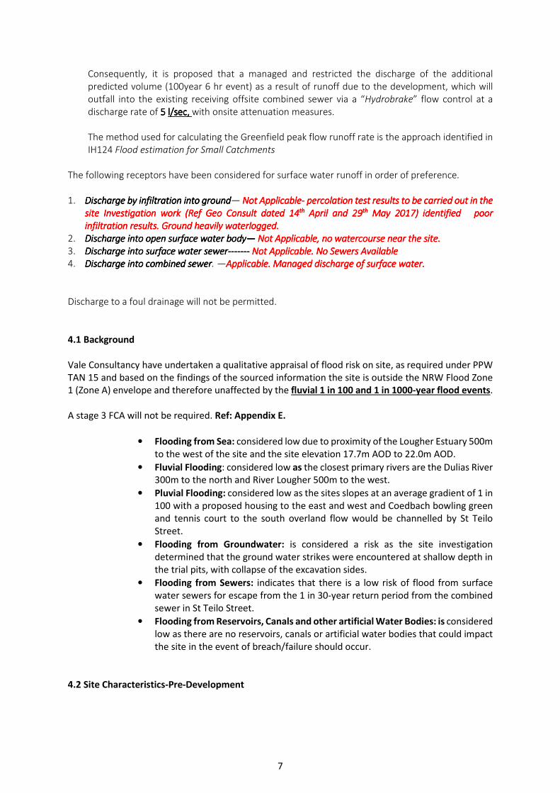
Appendix D
Proposed Development Layout

6
CLOSE
186
12
187
184
198
WYNDHAM
ST TEILO STREET
192
194
850
Bungalow
850
Bun
galo
w
850
Bungalow
850
Bungalow
850
Bun
galo
w
850
Bungalow
975
825
825
880
Bun
gal
ow
850
Bun
galo
w
1150
1150825
1
2
4
56
7
8
9
10
11
1213
14
15
16
17
1819
20
3
825
1150
975
975
975
975
1
1
12
2
2
g
g
g
g
g
g
g
g
g
g
g
g
g
g
g
g
g
g
3
3
3
4
4
4
5
5
5
6
6
6
7
7
7
8
8
8
9
9
9
10
10
10
11
11
11
20
20 20
19
19
19
18
17
18
18
17
17
16
15
16
16
15
15
14
14
14
12
12
12
13
13
13
2.4x43
Junction
Visibility
g
g
2.5 Visibility
splay to
drive No. 190
RESIDENTIAL DEVELOPMENT
ST TELIO STREETPONTARDULAIS
PLANNING LAYOUT
Site Boundary.
900mm high timber post and wire.
1800mm high timber hit & miss
fencing.
1800mm high timber gate.
Indicates concrete flag paved path/
patio area.
Indicative proposed turf planting.
Denotes opposite hand to working
drawing.
Front / rear door position.
Indicates shared private driveway &
Plot 3 drive.
Patio / french door position.
Indicative proposed tree and shrub
planting.
External bin storage location
g
KEY
TOTAL
HOUSE TYPE SQ.FT. NO.TOTALUNITREF.
2 STOREY2 STOREY
825975
0405
33004875
20 18455
825975
3 BED3 BED
2 STOREY 1150 03 34501150 4 BEDBUNGALOW 850 07 5950850 3 BED
880 BUNGALOW 3 BED 880 01 880
SCALE: 1/500@A3
DATE: DEC 2017
DRG NO: PL01
Optional conservatory

22
Appendix E
NRW Flood Maps

23


![Untitled-1 [aqua-me.ae] · 32,000 litres per hour (32m³/h) 130m³ IP65 Low pressure / High output Single Tube 3 bar 64W 14,000 hours 4m³/h 16,000 litres per hour (16m³/h) 65m³](https://img.pdfslide.us/doc/110x75/5e43dbf8ef87f27e717a2bd0/untitled-1-aqua-meae-32000-litres-per-hour-32mh-130m-ip65-low-pressure.jpg)