Embed Size (px)
Citation preview
DRAINAGE CRITERIA MANUAL (V. 2) HYDRAULIC STRUCTURES
HYDRAULIC STRUCTURES
CONTENTS
Section Page HS-
1.0 USE OF STRUCTURES IN DRAINAGE ......................................................................................... 1 1.1 Introduction ......................................................................................................................... 1 1.2 Channels Used for Boating................................................................................................. 2 1.3 Channel Grade Control Structures ..................................................................................... 3 1.4 Wetland Channel Grade Control ........................................................................................ 3 1.5 Conduit Outlet Structures ................................................................................................... 3 1.6 Bridges................................................................................................................................ 3 1.7 Transitions and Constrictions ............................................................................................. 3 1.8 Bends and Confluences...................................................................................................... 4 1.9 Rundowns........................................................................................................................... 4 1.10 Energy Dissipation.............................................................................................................. 4 1.11 Maintenance ....................................................................................................................... 4 1.12 Structure Safety and Aesthetics ......................................................................................... 4
2.0 CHANNEL GRADE CONTROL STRUCTURES (CHECK AND DROP STRUCTURES) ............... 6 2.1 Planning for the Future ....................................................................................................... 6
2.1.1 Outline of Section .................................................................................................. 6 2.1.2 Boatable Channels ................................................................................................ 7 2.1.3 Grass and Wetland Bottom Channels ................................................................... 8 2.1.4 Basic Approach to Drop Structure Design............................................................. 8
2.2 Drop Selection .................................................................................................................. 10 2.3 Detailed Hydraulic Analysis .............................................................................................. 10
2.3.1 Introduction .......................................................................................................... 10 2.3.2 Crest and Upstream Hydraulics........................................................................... 11 2.3.3 Water Surface Profile Downstream of the Crest ................................................. 11
2.3.7.1 Critical Depth Along a Drop Structure. ................................................... 11 2.3.7.2 Hydraulic Analysis. ................................................................................. 12 2.3.7.3 Manning’s n for Concrete, Boulders and Grouted Boulders................... 13 2.3.7.4 Avoid Low Froude Number Jumps in Grass-Lined Channels. ............... 13
2.3.4 Hydraulic Jump Location ..................................................................................... 14 2.3.5 Jump and Basin Length ....................................................................................... 15 2.3.6 Seepage Analysis ................................................................................................ 15 2.3.7 Force Analysis ..................................................................................................... 15
2.3.7.1 Shear Stress ........................................................................................... 16 2.3.7.2 Buoyant Weight of Structure................................................................... 16 2.3.7.3 Impact, Drag and Hydrodynamic Lift Forces .......................................... 17 2.3.7.4 Tur ning Force ........................................................................................ 17 2.3.7.5 Friction .................................................................................................... 17 2.3.7.6 Frost Heave ............................................................................................ 17 2.3.7.7 Seepage Uplift Pressure......................................................................... 17 2.3.7.8 Dynamic Pressure Fluctuations.............................................................. 18 2.3.7.9 Overall Analysis ...................................................................................... 19
2.4 Simplified Drop Structure Designs for District’s Grass-Lined Channels........................... 19 2.4.1 Introduction and Cautions.................................................................................... 19 2.4.2 Applicability of Simplified Channel Drop Designs................................................ 20 2.4.3 Simplified Grouted Sloping Boulder Drop Design ............................................... 21 2.4.4 Vertical Hard Basin Drops ................................................................................... 25
Rev. 2008-04 HS-i Urban Drainage & Flood Control District
2.5 Baffle Chute Drops ............................................................................................................29 2.6 Seepage Control ...............................................................................................................33
2.6.1 Seepage Analysis Methods..................................................................................33 2.6.2 Foundation/Seepage Control Systems ...................................................................34
2.7 Simplified Minimum Design Approach for Boatable Channels..........................................36 2.8 Construction Concerns: Grass-Lined Channels...............................................................37
2.8.1 Foundation/Seepage Control ...............................................................................37 2.8.2 Baffle Chute Construction ....................................................................................38 2.8.3 Vertical Hard Basin Construction .........................................................................38 2.8.4 Sloping Grouted Boulder Construction.................................................................38
2.9 Low-Flow Check and Wetland Structures .........................................................................39 3.1 General..............................................................................................................................60 3.2 Impact Stilling Basin ..........................................................................................................60
3.2.1 Modified Impact Basins for Smaller Outlets .........................................................61 3.2.2 Low-flow Modifications .........................................................................................61 3.2.3 Multiple Conduit Installations ...............................................................................62 3.2.4 General Design Procedure for Type IV Impact Basin ..........................................62
3.3 Pipe Outlet Rundowns.......................................................................................................64 3.3.1 Baffle Chute Rundown .........................................................................................64 3.3.2 Grouted Boulder Chute Rundown ........................................................................64
3.4 Low Tailwater Riprap Basins at Pipe Outlets ....................................................................64 3.4.1 General.................................................................................................................64 3.4.2 Objective ..............................................................................................................65 3.4.3 Low Tailwater Basin Design.................................................................................65
3.4.3.1 Finding Flow Depth and Velocity of Storm Sewer Outlet Pipe................65 3.4.3.2 Riprap Size..............................................................................................66 3.4.3.3 Basin Length ...........................................................................................67 3.4.3.4 Basin Width .............................................................................................68 3.4.3.5 Other Design Requirements....................................................................68
3.5 Culvert Outlets...................................................................................................................69 4.0 BRIDGES .......................................................................................................................................84
4.1 Basic Criteria .....................................................................................................................85 4.1.1 Design Approach..................................................................................................85 4.1.2 Bridge Opening Freeboard...................................................................................85
4.2 Hydraulic Analysis .............................................................................................................85 4.2.1 Expression for Backwater.....................................................................................86 4.2.2 Backwater Coefficient...........................................................................................87 4.2.3 Effect of M and Abutment Shape (Base Curves) .................................................87 4.2.4 Effect of Piers (Normal Crossings).......................................................................88
4.3 Design Procedure..............................................................................................................88 5.0 TRANSITIONS AND CONSTRICTIONS........................................................................................94
5.1 Introduction........................................................................................................................94 5.2 Transition Analysis ............................................................................................................94
5.2.1 Subcritical Transitions ..........................................................................................94 5.2.2 Supercritical Transition Analysis ..........................................................................95
5.3 Constriction Analysis .........................................................................................................95 5.3.1 Constrictions With Upstream Subcritical Flow .....................................................95 5.3.2 Constrictions With Upstream Supercritical Flow ..................................................96
6.0 BENDS AND CONFLUENCES ......................................................................................................98 6.1 Introduction........................................................................................................................98 6.2 Bends ................................................................................................................................98
6.2.1 Subcritical Bends..................................................................................................98 6.2.2 Supercritical Bends ..............................................................................................98
HS-ii 2008-04 Urban Drainage & Flood Control District
DRAINAGE CRITERIA MANUAL (V. 2) HYDRAULIC STRUCTURES
6.3 Confluences.................................................................................................................... 100 6.3.1 Subcritical Flow Confluence Design .................................................................. 100
7.0 RUNDOWNS ............................................................................................................................... 103 7.1 Cross Sections................................................................................................................ 103 7.2 Design Flow .................................................................................................................... 103 7.3 Flow Depth...................................................................................................................... 104 7.4 Outlet Configuration for Trickle Channel ........................................................................ 104 7.5 Outlet Configuration for Wetland Channel...................................................................... 104 7.6 Grouted Boulder Rundowns ........................................................................................... 104
8.0 MAINTENANCE........................................................................................................................... 106 8.1 General ........................................................................................................................... 106 8.2 Access ............................................................................................................................ 106 8.3 Maintenance Optimization .............................................................................................. 106
9.0 BOATABLE DROPS .................................................................................................................... 107 9.1 Introduction ..................................................................................................................... 107 9.2 Retrofitting Existing Structures ....................................................................................... 107
9.2.1 Downstream Face.............................................................................................. 107 9.2.2 Boat Chute......................................................................................................... 107 9.2.3 Sharp Edges ...................................................................................................... 107 9.2.4 Barriers and Signing .......................................................................................... 107 9.2.5 Portages ............................................................................................................ 108
9.3 Safety.............................................................................................................................. 108 10.0 STRUCTURE AESTHETICS, SAFETY AND ENVIRONMENTAL IMPACT ............................... 109
10.1 Introduction ..................................................................................................................... 109 10.2 Aesthetics and Environmental Impact ............................................................................ 109 10.3 Safety.............................................................................................................................. 110
11.0 CHECKLIST................................................................................................................................. 113 12.0 REFERENCES ............................................................................................................................ 116
TABLES
Table HS-1—Non-Boatable Drop Structure Selection for 3- to 5-Foot High Drops and Flows of 0 to 15,000 cfs .................................................................................................................. 10
Table HS-2—Suggested Approximate Manning’s Roughness Parameter at Design Discharge for Sloping Drops .............................................................................................................. 13
Table HS-3—Nominal Limit of Maximum Pressure Fluctuations within the Hydraulic Jump (Toso, 1986)............................................................................................ 19
Table HS-4—Grouted Sloping Boulder Drops: Minimum Design Criteria for Grass-Lined Channels Meeting the District’s Maximum Depth and Velocity Criteria............................................ 23
Table HS-5—Boulder Sizes for Various Rock Sizing Parameters ............................................................. 25 Table HS-6—Vertical Drops With Grouted Boulder Basin: Simplified Design Criteria for
Small Vertical Drops in Grass-Lined Channels Meeting District Criteria.......................... 29 Table HS-7—Lane’s Weighted Creep: Recommended Ratios ................................................................. 34 Table HS-8—General Cutoff Technique Suitability .................................................................................... 35 Table HS-9—Median (i.e., D50) Size of District's Riprap/Boulder ............................................................... 67 Table HS-10—Subcritical Transition Energy Loss Coefficients ................................................................. 95
Rev. 2008-04 HS-iii Urban Drainage & Flood Control District
FIGURES
Figure HS-1—Probable Range of Drop Choices and Heights ....................................................................41 Figure HS-2—Hydraulic Analysis and Typical Forces at Sloping Boulder Drops .......................................42 Figure HS-3—Recommended Manning’s n for Flow Over B18 to B42 Grouted Boulders .........................43 Figure HS-4—Coefficient of Pressure Fluctuation, Cp, at a Hydraulic Jump ..............................................44 Figure HS-5—Pressure Fluctuation Coefficient, Cp, Normalized for Consideration of Slope
and Jump Beginning on Slope ..........................................................................................44 Figure HS-6—Coefficient of Pressure Fluctuation, Cp, in a Jump on a USBR II or III Basin ......................45 Figure HS-7A—Grouted Sloping Boulder Drop with Trickle Channel for Stabilized Channels
in Erosion Resistant Soils..................................................................................................46 Figure HS-7B—Grouted Sloping Boulder Drop With Low-Flow Channel for Stabilized Channels
in Erosion Resistant Soils..................................................................................................48 Figure HS-7C—Grouted Sloping Boulder Drop for Unstable Channels in Erosive Soils............................50 Figure HS-7D— Grouted Sloping Boulder Drop Details. ............................................................................52 Figure HS-8—Specifications and Placement Instructions for Grout in Sloping Boulder Drops. .................53 Figure HS-9—Vertical Hard Basin Drop......................................................................................................54 Figure HS-10—Vertical Drop Hydraulic System .........................................................................................55 Figure HS-11—Baffle Chute Drop Standard USBR Entrance ....................................................................56 Figure HS-12—Baffle Chute Crest Modifications and Forces.....................................................................57 Figure HS-13a—Control Check for Stable Floodplain – Concrete Wall......................................................58 Figure HS-13b—Control Check for Stable Floodplain – Sheet Piling Type................................................59 Figure HS-14—General Design Dimensions for a USBR Type VI Impact Stilling Basin ............................71 Figure HS-15—Basin Width Diagram for the USBR Type VI Impact Stilling Basin)...................................72 Figure HS-16a Modified Impact Stilling Basin for Conduits 18” to 48” in Diameter ....................................73 Figure HS-16b. Impact Stilling Basin for Pipes Smaller than 18” in Diameter Upstream of Forebays. ......75 Figure HS-17—Baffle Chute Pipe Outlet.....................................................................................................76 Figure HS-18—Grouted Boulder Rundown.................................................................................................77 Figure HS-19—Low Tailwater Riprap Basins for Storm Sewer Pipe Outlets—
Low Tailwater Basin at Pipe Outlets .................................................................................79 Figure HS-19a—Concrete Flared End Section with Cutoff Wall for all Pipe Outlets ..................................80 Figure HS-20a—Low Tailwater Riprap Basins for Storm Sewer Pipe Outlets—
Discharge and Flow Area Relationships for Circular and Rectangular Pipes...................81 Figure HS-20b—Low Tailwater Riprap Basins for Storm Sewer Pipe Outlets—
Brink Depth for Horizontal Pipe Outlets ............................................................................82 Figure HS-20c—Low Tailwater Riprap Basins for Storm Sewer Pipe Outlets—
Riprap Selection Chart for Low Tailwater Basin at Pipe Outlet.........................................83 Figure HS-21—Normal Bridge Crossing Designation .................................................................................91 Figure HS-22—Base Curves for Wingwall Abutments................................................................................92 Figure HS-23—Base Curves for Spillthrough Abutments ...........................................................................92 Figure HS-24—Incremental Backwater Coefficient for Pier ........................................................................93 Figure HS-25—Transition Types.................................................................................................................97 Figure HS-26—Channel Junction Definition Sketches..............................................................................102
HS-iv 2008-04 Urban Drainage & Flood Control District
DRAINAGE CRITERIA MANUAL (V. 2) HYDRAULIC STRUCTURES
Figure HS-27—Rundown.......................................................................................................................... 105 Figure HS-28—Hydraulic Jump Tailwater Stages as Related to Boating Hazards.................................. 112
PHOTOGRAPHS
Photograph HS-1—Denver’s Harvard Gulch Flood Control Project introduced the baffle chute drop structure to urban flood control in 1966. Vegetation and time have made the structure part of the city’s urban poetry. .......................................................................................... 1
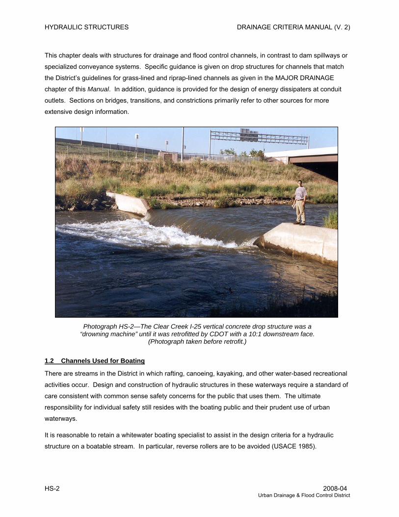
Photograph HS-2—The Clear Creek I-25 vertical concrete drop structure was a “drowning machine” until it was retrofitted by CDOT with a 10:1 downstream face. (Photograph taken before retrofit.) .................................................................................................. 2
Photograph HS-3—Stepped grouted sloping boulder drop structures such as in Denver’s Bible Park can be safe, aesthetic, and provide improved aquatic habitat besides performing their primary hydraulic function of energy dissipation..................................... 5
Photograph HS-4—This grade control structure on the South Platte River was a hazard to the boating public until it was retrofitted by the CDOT. Here, a rescue is supervised by Colorado Governor Richard Lamm who was enjoying a rafting trip with friends and the Denver Water Rescue Team. ................................................................................................... 7
Photograph HS-5—Example of stepped downstream face for a sloping boulder drop structure. Note dissipation of energy at each step for low flow. .................................................................... 20
Photograph HS-6—Detail of the grouted sloping boulder drop with a trickle channel section creating the sight and sound of cascading water. ......................................................................... 21
Photograph HS-7—An overall view of the drop structure from the previous page is illustrated here to emphasize the opportunities available for creating an attractive urban hydraulic setting for the riparian corridor....................................................................................................... 22
Photograph HS-8—A vertical hard basin drop structure can be an effective tool for controlling grade, but it is not as desirable as a grouted sloping boulder drop because of safety concerns and aesthetics................................................................................................................................ 26
Photograph HS-9—Close-up of the inside workings of a baffle chute drop after more than three decades of service................................................................................................................ 30
Photograph HS-10—Boatable channels of the District waterways provide enjoyment to a wide variety of citizens. The South Platte River example in this photograph provides an easily accessible boating experience....................................................................................................... 36
Photograph HS-11—Unprotected urban channels can experience bank erosion and degradation when established design criteria are not used. The invert of pipe used to be at invert of channel before degradation occurred........................................................................................ 37
Photograph HS-12—Upstream and downstream views of a low tailwater basin in Douglas County protecting downstream wetland area. Burying and revegetation of the rock would blend the structure better with the adjacent terrain. ................................................................................ 67
Rev. 2008-04 HS-v Urban Drainage & Flood Control District
HS-vi 2008-04 Urban Drainage & Flood Control District
Photograph HS-13—Culvert outlets when left unprotected cause downstream erosion. The designer’s job is not complete until provisions are made to protect the outlet. Use of vegetated soil-riprap would blend this structure better into the natural landscape. ...........69
Photograph HS-14—A stable channel at bridges is important and includes caring for the stream downstream of the bridge as shown here on Cherry Creek...............................................84
Photograph HS-15—A failed rundown that relied upon a geotextile membrane for stability. ...................103
Photograph HS-16—The unsightly and hazardous 8-foot-high Brown Ditch weir was replaced with three low-head drop structures having a 10:1 downstream slope and a boat chute. The resulting improvement by the USACE has provided for safe, enjoyable recreational boating. ....................................................................................................108
Photograph HS-17—Grouted sloping boulder drops can be built in series to create pleasing amenities and to provide stable and long-lived grade control structures. ....................................109
Photograph HS-18—Warning signs can be used to help achieve public boating safety, but signs cannot in themselves serve as a substitute for an appropriate standard of care in the design of a reasonable grade control structures on a boatable waterway.........................111
DRAINAGE CRITERIA MANUAL (V. 2) HYDRAULIC STRUCTURES
1.0 USE OF STRUCTURES IN DRAINAGE
1.1 Introduction
Hydraulic structures are used to guide and control water flow velocities, directions and depths, the
elevation and slope of the streambed, the general configuration of the waterway, and its stability and
maintenance characteristics.
Careful and thorough hydraulic engineering is justified for hydraulic structures. Consideration of
environmental, ecological, and public safety objectives should be integrated with hydraulic engineering
design. The proper application of hydraulic structures can reduce initial and future maintenance costs by
managing the character of the flow to fit the environmental and project needs.
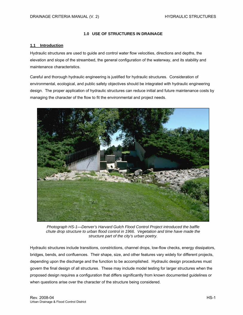
Photograph HS-1—Denver’s Harvard Gulch Flood Control Project introduced the baffle chute drop structure to urban flood control in 1966. Vegetation and time have made the
structure part of the city’s urban poetry.
Hydraulic structures include transitions, constrictions, channel drops, low-flow checks, energy dissipators,
bridges, bends, and confluences. Their shape, size, and other features vary widely for different projects,
depending upon the discharge and the function to be accomplished. Hydraulic design procedures must
govern the final design of all structures. These may include model testing for larger structures when the
proposed design requires a configuration that differs significantly from known documented guidelines or
when questions arise over the character of the structure being considered.
Rev. 2008-04 HS-1 Urban Drainage & Flood Control District
HYDRAULIC STRUCTURES DRAINAGE CRITERIA MANUAL (V. 2)
This chapter deals with structures for drainage and flood control channels, in contrast to dam spillways or
specialized conveyance systems. Specific guidance is given on drop structures for channels that match
the District’s guidelines for grass-lined and riprap-lined channels as given in the MAJOR DRAINAGE
chapter of this Manual. In addition, guidance is provided for the design of energy dissipaters at conduit
outlets. Sections on bridges, transitions, and constrictions primarily refer to other sources for more
extensive design information.
Photograph HS-2—The Clear Creek I-25 vertical concrete drop structure was a “drowning machine” until it was retrofitted by CDOT with a 10:1 downstream face.
(Photograph taken before retrofit.)
1.2 Channels Used for Boating
There are streams in the District in which rafting, canoeing, kayaking, and other water-based recreational
activities occur. Design and construction of hydraulic structures in these waterways require a standard of
care consistent with common sense safety concerns for the public that uses them. The ultimate
responsibility for individual safety still resides with the boating public and their prudent use of urban
waterways.
It is reasonable to retain a whitewater boating specialist to assist in the design criteria for a hydraulic
structure on a boatable stream. In particular, reverse rollers are to be avoided (USACE 1985).
HS-2 2008-04 Urban Drainage & Flood Control District
DRAINAGE CRITERIA MANUAL (V. 2) HYDRAULIC STRUCTURES
1.3 Channel Grade Control Structures
Grade control structures, such as check structures and drop structures, provide for energy dissipation and
thereby result in a mild slope in the upstream channel reaches. The geometry at the crest of these
structures can effectively control the upstream channel stability and, to an extent, its ultimate
configuration.
A drop structure traverses the entire waterway, including the portion that carries the major flood. A check
structure is similar, but is constructed to stabilize the low-flow channel (i.e., one carrying the minor or
lesser flood) in artificial or natural drainageways. It crosses only the low-flow portion of the waterway or
floodplain. During a major flood, portions of the flow will circumvent the check. Overall channel stability is
maintained because degradation of the low-flow channel is prevented. Typically, the 2-year flows are
contained in the protected zone so that the low-flow channel does not degrade downward, potentially
undermining the entire waterway.
1.4 Wetland Channel Grade Control
Wetland channels, whether low-flow channels or from bank to bank, require modest slopes not exceeding
about 0.3%. Grade control structures are often required for stability. Due to the environmental nature of
the wetlands, the grade control structures are planned and designed to be compatible with a wetland
environment. Wetland channels do not need a trickle channel, but where used, the trickle channel should
not lower the wetland water table more than 12 inches.
1.5 Conduit Outlet Structures
Design criteria given in this chapter are for structures specifically designed to dissipate flow energy at
conduit outlets to the open waterway. These types of structures are typically located at storm sewer
outlets. Design criteria for culverts and storm sewers that discharge in-line with the receiving channel are
described in the MAJOR DRAINAGE chapter of this Manual.
1.6 Bridges
Bridges have the advantage of being able to cross the waterway without disturbing the flow. However, for
practical, economic, and structural reasons, abutment encroachments and piers are often located within
the waterway. Consequently, the bridge structure can cause adverse hydraulic effects and scour
potential that must be evaluated and addressed as part of each design project.
1.7 Transitions and Constrictions
Channel transitions are typically used to alter the cross-sectional geometry, to allow the waterway to fit
within a more confined right-of-way, or to purposely accelerate the flow to be carried by a specialized high
velocity conveyance. Constrictions can appreciably restrict and reduce the conveyance in a manner that
is either detrimental or beneficial. For example, a bridge, box culvert, or constriction may increase the
upstream flooding by encroaching too far into the floodplain conveyance, whereas in another situation a
Rev. 2008-04 HS-3 Urban Drainage & Flood Control District
HYDRAULIC STRUCTURES DRAINAGE CRITERIA MANUAL (V. 2)
hydraulic control structure can be employed to purposely induce an upstream spill into an off-stream
storage facility.
1.8 Bends and Confluences
General considerations for lined channels and conduits are discussed in the MAJOR DRAINAGE chapter
of this Manual. Additional emphasis is added herein for certain situations. Channels and conduits that
produce supercritical flow may require special structural or design considerations. This discussion is
limited since these types of structures are generally associated with hydraulic performance exceeding the
recommended criteria for grass-lined channels. Extensive study, specialized modeling and/or analysis
may be required for these situations.
On the other hand, confluences are commonly encountered in design. Relative flow rates can vary
disproportionately with time so that high flows from either upstream channel can discharge into the
downstream channel when it is at high or low level. Depending on the geometry of the confluence, either
condition can have important consequences, such as supercritical flow and hydraulic jump conditions,
and result in the need for structures
1.9 Rundowns
A rundown is used to convey storm runoff from high on the bank of an open channel to the low-flow
channel of the drainageway or into a detention facility. The purpose is to control erosion and head cutting
from concentrated flow. Without such rundowns, the concentrated flow will create erosion.
1.10 Energy Dissipation
The energy of moving water is known as kinetic energy, while the stored energy due to elevation is
potential energy. A properly sloped open channel will use up the potential energy in a uniform manner
through channel roughness without the flow being accelerated. A grade control structure (i.e., drop and
check) converts potential energy to kinetic energy under controlled conditions. Selection of the optimum
spacing and vertical drop is the work of the hydraulic engineer. Many hydraulic structures deal with
managing kinetic energy—to dissipate it in a reasonable manner, to conserve it at structures such as
transitions and bridges, or occasionally to convert kinetic to potential energy using a hydraulic jump.
Thus, managing energy involves understanding and managing the total energy grade line of flowing
water.
1.11 Maintenance
Urban drainage facilities should not be built if they cannot be properly maintained on a long-term basis.
This means that suitable access must be provided, a maintenance plan must be developed and funded,
and the drainage facilities must be maintained in accordance with public works standards.
1.12 Structure Safety and Aesthetics
The design of structures must consider safety of flood control workers and the general public, especially
HS-4 2008-04 Urban Drainage & Flood Control District
DRAINAGE CRITERIA MANUAL (V. 2) HYDRAULIC STRUCTURES
when multiple uses are intended. Regulations and interpretations vary from community to community and
may change with time. There are some inherent safety risks in any waterway that have to be recognized
by the public, designers, and government officials. General suggestions are given in regard to safety;
however, the designer must use a reasonable standard of care for the particular structure being designed
or retrofitted that includes evaluation of present or likely future public access and uses such as recreation.
The designer should give special consideration to structures located in waterways where boating is likely
to occur. These structures need to be designed to avoid known hazards, such as reverse rollers
(Leutheusser and Birk 1991), often referred to by some as “keepers.”
Aesthetic appearance of structures in urban areas is also important. Structures can be designed with
various configurations, different materials, and incorporation of adjacent landscaping to produce a
pleasing appearance and good hydraulic function and to enhance the environmental and ecological
character of the channel and floodplain. The incorporation of wetland vegetation, native grasses, and
shrubs into the design adds to their aesthetics and provides erosion control and water quality functions.
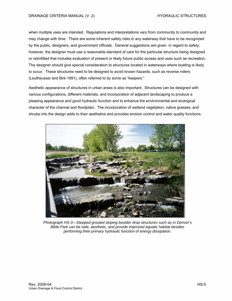
Photograph HS-3—Stepped grouted sloping boulder drop structures such as in Denver’s Bible Park can be safe, aesthetic, and provide improved aquatic habitat besides
performing their primary hydraulic function of energy dissipation.
Rev. 2008-04 HS-5 Urban Drainage & Flood Control District
HYDRAULIC STRUCTURES DRAINAGE CRITERIA MANUAL (V. 2)
2.0 CHANNEL GRADE CONTROL STRUCTURES (CHECK AND DROP STRUCTURES)
2.1 Planning for the Future
Channel grade control structures (typically check structures and drop structures) should be designed for
future fully developed basin conditions. In the use of a natural channel, the effects of future hydrology
and potential down cutting must be included so that the natural channel is properly stabilized.
Urbanization will create a base flow that, over time, will cause down cutting if not managed with grade
control structures.
“Drop structures” are broadly defined. They establish a stable stream grade and hydraulic condition.
Included are structures built to restore damaged channels, those that prevent accelerated erosion caused
by increased runoff, and grade control drops in new channels. Drop structures provide special hydraulic
conditions that allow a drop in water surface and/or channel grade. The supercritical flow may go through
a hydraulic jump and then return to subcritical flow.
The focus of these criteria is on channel drops with primary emphasis on grass-lined channels. Check
structures may be used to stabilize the natural low-flow channel in an unmodified floodplain. Thus, check
structures also require additional consideration of the wider major flood path extending around the
structure abutments.
Specific design guidance is presented for the following basic categories of drop structures: baffle chute
drops (BCD), grouted sloping boulder drops (GSB), and vertical hard basin drops (VHB).
All drop structures should be evaluated after construction. Bank and bottom protection and adjustments
may be needed when secondary erosion tendencies are revealed. It is advisable to establish
construction contracts and budgets with this in mind. Use of standardized design methods for the types
of drops suggested herein will reduce the need for secondary design refinements.
The design of the drop structure crest and provisions for the trickle or low-flow channel directly affect the
ultimate configuration of the upstream channel. A shallow and/or dispersed trickle configuration will tend
to result in some aggradation and a wetter channel bottom than might be associated with a wetland
channel bottom. However, the wetland channel design would not contain a trickle channel because the
low flows would be spread out uniformly across the entire channel bottom.
A higher unit flow will pass through the trickle or low-flow area than will pass through other portions of the
channel cross section. This situation must be considered in design to avoid destabilization of the drop
and the channel.
2.1.1 Outline of Section The following section provides guidelines to aid in the selection of alternate types of drops, particularly
those used for grass-lined channels. Drops for boatable channels are described separately.
HS-6 2008-04 Urban Drainage & Flood Control District
DRAINAGE CRITERIA MANUAL (V. 2) HYDRAULIC STRUCTURES
Much of the section is oriented toward hydraulic design and criteria for drop structures. There are two
levels of analysis given. One level of hydraulic analysis is “detailed.” All steps that are important are
described, along with design aids. The other level is “simplified.” Layouts of typical drops, particularly the
crest configuration and related channel, are given which result in grass-lined channel hydraulic
performance at the maximum depths and velocities normally allowed by the District for these types of
channels. The use of these charts allows a quicker start, but certain steps from the “detailed” analysis will
still be necessary, particularly the effects of greater unit flows in the low-flow or trickle channel area.
Hydraulic analysis sections are followed by further details appropriate to each of the types of drops that
are recommended for grass-lined channels and boatable channel drops. Then, further information on
seepage analysis, construction concerns, and low-flow channel structures is given.
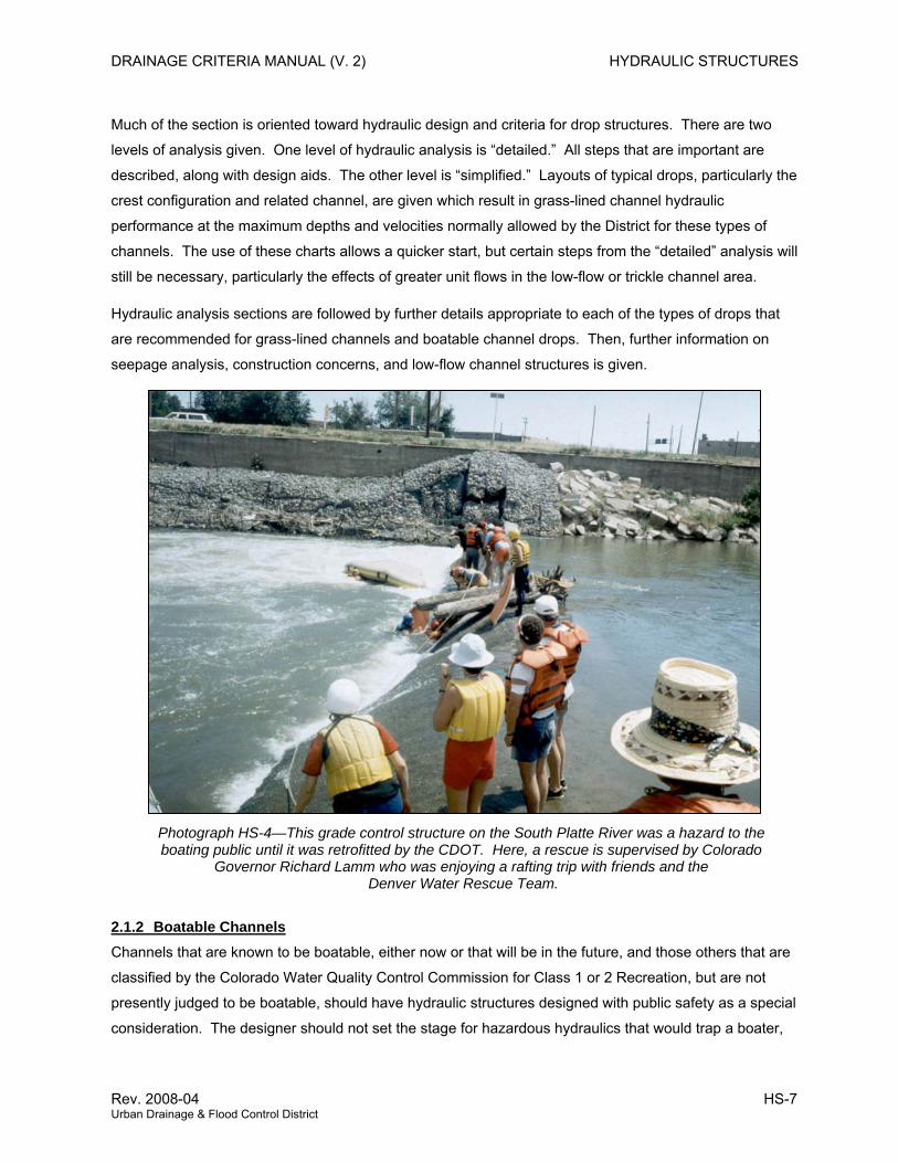
Photograph HS-4—This grade control structure on the South Platte River was a hazard to the boating public until it was retrofitted by the CDOT. Here, a rescue is supervised by Colorado
Governor Richard Lamm who was enjoying a rafting trip with friends and the Denver Water Rescue Team.
2.1.2 Boatable Channels Channels that are known to be boatable, either now or that will be in the future, and those others that are
classified by the Colorado Water Quality Control Commission for Class 1 or 2 Recreation, but are not
presently judged to be boatable, should have hydraulic structures designed with public safety as a special
consideration. The designer should not set the stage for hazardous hydraulics that would trap a boater,
Rev. 2008-04 HS-7 Urban Drainage & Flood Control District
HYDRAULIC STRUCTURES DRAINAGE CRITERIA MANUAL (V. 2)
such as at a drop structure having a reverse roller that may develop as the hydraulic jump becomes
submerged.
Designs for boatable channels, grade control structures, and low-head dams have to prevent the
development of submerged hydraulic jumps, have a gently sloped or stepped downstream face, and not
have a deep stilling basin that would encourage the creation of a submerged hydraulic jump. One design
approach is to direct the hydraulic momentum at the bottom of the drop at a relatively flat angle to help
prevent a reverse roller. A downstream face on a drop having large grouted boulders and high roughness
that is sloped at 10(H) to 1(V) has been used successfully on several projects along the South Platte
River and on Clear Creek, permitting safe passage of boaters as the move over them.
Drop structures or low-head dams in boatable channels should incorporate a boat chute designed in
accordance with carefully planned components that are consistent with recreational requirements for
boater safety. Often, physical model studies are used to verify the efficacy of the proposed design.
Hydraulic structures on boatable channels should not create obstructions that would pin a canoe, raft or
kayak, and sharp edges should be avoided.
2.1.3 Grass and Wetland Bottom Channels Structures for grass and wetland bottom (i.e., non boatable) channels are described in detail on the
following pages and are represented by a variety of choices and shapes to suit the particular site and
related hydraulics.
Based on experience, the sloped drop has been found to be more desirable than the vertical wall drop
with a hardened energy dissipation basin. Vertical drops can create a reverse roller and backflow eddies
that have been know to trap boaters. Because of boater and public safety concerns, vertical drops are
less desirable than sloping drops in urban areas. Other disadvantages of a vertical drop include the
turbulence and erosive effect of the falling water on the drop structure, necessitating high maintenance.
It is desirable to limit the height of most drops to 3 to 5 feet to avoid excessive kinetic energy and to avoid
the appearance of a massive structure, keeping in mind that the velocity of falling water increases
geometrically with the vertical fall distance. If vertical drops are use, it is best to limit their height to 3 feet.
2.1.4 Basic Approach to Drop Structure Design The basic approach to design of drop structures includes the following steps:
1. Determine if the channel is, or will be, a boatable channel. If boatable, the drop or check
structure should use a standard of care consistent with adequate public safety to provide for
boater passage.
2. Define the representative maximum channel design discharge (often the 100-year) and other
discharges appropriate for analysis, (e.g., low or trickle flows and other discharges expected to
HS-8 2008-04 Urban Drainage & Flood Control District
DRAINAGE CRITERIA MANUAL (V. 2) HYDRAULIC STRUCTURES
occur on a more frequent basis) which may behave differently. All channels need to be designed
for stability by limiting their erosion and degradation potential and for longevity by analyzing all
the effects on channel stability at levels of flow, including the 100-year flood.
3. Approximate the channel dimensions and flow parameters including longitudinal slope. Identify
the probable range of drop choices and heights with the aid of Figure HS-1.
4. Select drop structure alternatives to be considered for grass-lined or other channel types (see
Section 2.2).
5. Decide if channel performance at maximum allowable criteria (i.e., velocity, depths, etc.) for
grass-lined channels is practical or desirable. If not, or if the design flow is over 7,500 cfs, go to
step 6; otherwise, the simplified design charts in Section 2.3.3 may be used to size the basic
configuration of the crest. The designer should review the precautions given and the limits of
application with respect to site conditions. Then the crest section and upstream channel
transition will need to be refined for incorporation of the trickle or low-flow channel. This requires
review of the upstream water surface profile and the supercritical flow downstream of the crest
through the dissipation zone of the drop. Under conditions of a submerged jump due to a high
tailwater elevation, steps to mitigate the reverse roller should be evaluated. If measures are
taken to provide baffles or large boulders to break up the jet, then extensive analysis of the trickle
zone hydraulics is not necessary. The steps involved are discussed in Section 2.3. Then go to
step 7.
6. For refined analysis and optimal design of grass-lined channel drop structures, use the “detailed”
hydraulic analysis in Section 2.3.2.
7. Perform soils and seepage analyses as necessary to obtain foundation design information.
8. In the case of drops for grass-lined channels, comply with the minimum specific criteria and follow
the guidelines for the recommended types of drops (baffle chute, vertical hard basin, and grouted
sloping boulder) presented in Section 2.3.4. Otherwise, provide a complete hydraulic analysis
documenting the performance and design for the type of drop or other type of channel being
considered. For channels with alluvial beds that present an erosion/degradation risk, a complete
stability and scour analysis should be completed, accompanied by a geotechnical investigation
and seepage analysis.
9. Use specific design criteria and guidelines to determine the final drop structure flow
characteristics, dimensions, material requirements, and construction methods.
10. Obtain necessary environmental permits, such as a Section 404 permit.
Rev. 2008-04 HS-9 Urban Drainage & Flood Control District
HYDRAULIC STRUCTURES DRAINAGE CRITERIA MANUAL (V. 2)
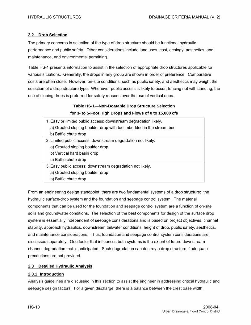
2.2 Drop Selection
The primary concerns in selection of the type of drop structure should be functional hydraulic
performance and public safety. Other considerations include land uses, cost, ecology, aesthetics, and
maintenance, and environmental permitting.
Table HS-1 presents information to assist in the selection of appropriate drop structures applicable for
various situations. Generally, the drops in any group are shown in order of preference. Comparative
costs are often close. However, on-site conditions, such as public safety, and aesthetics may weight the
selection of a drop structure type. Whenever public access is likely to occur, fencing not withstanding, the
use of sloping drops is preferred for safety reasons over the use of vertical ones.
Table HS-1—Non-Boatable Drop Structure Selection for 3- to 5-Foot High Drops and Flows of 0 to 15,000 cfs
1. Easy or limited public access; downstream degradation likely. a) Grouted sloping boulder drop with toe imbedded in the stream bed b) Baffle chute drop
2. Limited public access; downstream degradation not likely. a) Grouted sloping boulder drop b) Vertical hard basin drop c) Baffle chute drop 3. Easy public access; downstream degradation not likely. a) Grouted sloping boulder drop b) Baffle chute drop
From an engineering design standpoint, there are two fundamental systems of a drop structure: the
hydraulic surface-drop system and the foundation and seepage control system. The material
components that can be used for the foundation and seepage control system are a function of on-site
soils and groundwater conditions. The selection of the best components for design of the surface drop
system is essentially independent of seepage considerations and is based on project objectives, channel
stability, approach hydraulics, downstream tailwater conditions, height of drop, public safety, aesthetics,
and maintenance considerations. Thus, foundation and seepage control system considerations are
discussed separately. One factor that influences both systems is the extent of future downstream
channel degradation that is anticipated. Such degradation can destroy a drop structure if adequate
precautions are not provided.
2.3 Detailed Hydraulic Analysis
2.3.1 Introduction Analysis guidelines are discussed in this section to assist the engineer in addressing critical hydraulic and
seepage design factors. For a given discharge, there is a balance between the crest base width,
HS-10 2008-04 Urban Drainage & Flood Control District
DRAINAGE CRITERIA MANUAL (V. 2) HYDRAULIC STRUCTURES
upstream and downstream flow velocities, the Froude number in the drop basin, and the location of the
jump. These parameters must be optimized for each specific application.
There are two levels of analysis possible. The first involves detailed analysis of all hydraulic conditions
and leads to an optimal design for each structure. The concepts involved are described herein, and
numerous references are available for more detailed information. The second level of analysis is a
simpler approach that is based on configurations that will be adequate at the limits of permissible grass-
lined channel criteria as described in Section 2.4.
There are two general categories of drops: sloping and vertical. For safety reasons, vertical drops
should be avoided under urban conditions for public safety reasons. Performance of vertical or smooth
sloping drops into a hard basin is relatively well documented. Their hydraulic analysis is briefly described
herein. The design criteria for other drops such as vertical plunge pools and baffle chutes is based on
empirical data and model studies.
2.3.2 Crest and Upstream Hydraulics After preliminary channel layout has indicated probable drop location and heights (see the MAJOR
DRAINAGE chapter for guidance, including the design spreadsheet UD-Channels), analysis and design
begins with review of the crest section at the top of the drop. As flow passes through critical depth near
the crest, upstream hydraulics are separated from downstream. Usually, the key task here is to
determine critical depth at the crest based on the entire section. The critical flow state needs to be
verified to ascertain that the downstream tailwater does not submerge the crest and effectively controls
the hydraulics above the crest. If the downstream tailwater controls, then the structure must still be
evaluated as a check for the peak discharge and as a drop at lower flows, if appropriate.
With control at the drop crest, water surface profile computations are used to establish the upstream
abutment and bank heights. Computations should include a transition head loss, typically ranging from
0.3 (modest transitions in grass-lined channels) to 0.5 (channels approaching abrupt constrictions) times
the change in velocity head across the transition (see Section 5.2), and allowance for the end contraction
where the flow may effectively separate from the abutment end walls. Refer to Section 5.0 and standard
hydraulic references for guidance (Chow 1959, Rouse 1949, and USACE 1994).
2.3.3 Water Surface Profile Downstream of the Crest
2.3.7.1 Critical Depth Along a Drop Structure. Although this discussion concerns the hydraulics below the crest of a drop structure, the fundamental
analysis of this hydraulics is established by the crest conditions. Main, low-flow and trickle channel
regions are considered separately. Although the actual location of critical depth can vary according to the
channel, transition, and drop geometry, the assumption is made that critical depth occurs at the crest, in a
horizontal straight line across the crest section.
Rev. 2008-04 HS-11 Urban Drainage & Flood Control District
HYDRAULIC STRUCTURES DRAINAGE CRITERIA MANUAL (V. 2)
The assumption of critical flow conditions across the crest is illustrated conceptually by the diagrams in
Figures HS-2 and the corresponding energy level across the section. At any point across the crest, the
velocity is a function of the critical depth at that point. This causes a higher unit discharge applied to the
trickle channel zone than across the main channel flow area. Figure HS-2 also illustrates that the water
surface and energy grade line profiles will be different at the trickle (or low-flow) portions of the section
than in the main channel flow zones and the forces exerted by flow on individual boulders on the sloping
face of the drop.
2.3.7.2 Hydraulic Analysis. After review of the crest and upstream hydraulics, the analysis proceeds to the supercritical flow and the
hydraulic jump downstream. It is here that the designer should give special consideration to the potential
of reverse rollers and avoid them in boatable channels and, where practicable, in grass-lined channels.
Little flow dispersal from the trickle or low-flow zone to the main zone occurs through the supercritical
portion of the drop. (Flow expansion is more likely downstream of the jump.) Therefore, unit discharge
determined at the crest for either the trickle channel or the main portion of the drop is assumed to remain
constant. The required basin length varies between these zones. Baffle chutes are the only type of drop
where this distinction is not significant because the baffles break up the flow patterns and spread the flow
more evenly over the width of the channel.
With the exception of baffle chute drops, separate analysis should be performed to evaluate the main
drop and trickle or low-flow channel zones, as follows:
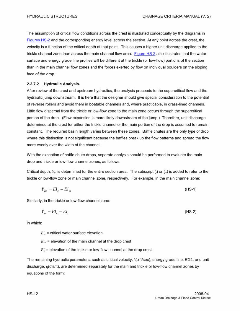
Critical depth, Yc, is determined for the entire section area. The subscript (t) or (m) is added to refer to the
trickle or low-flow zone or main channel zone, respectively. For example, in the main channel zone:
mccm ElElY −= (HS-1)
Similarly, in the trickle or low-flow channel zone:
tcct ElElY −= (HS-2)
in which:
Elc = critical water surface elevation
Elm = elevation of the main channel at the drop crest
Elt = elevation of the trickle or low-flow channel at the drop crest
The remaining hydraulic parameters, such as critical velocity, Vc (ft/sec), energy grade line, EGL, and unit
discharge, q(cfs/ft), are determined separately for the main and trickle or low-flow channel zones by
equations of the form:
HS-12 2008-04 Urban Drainage & Flood Control District
DRAINAGE CRITERIA MANUAL (V. 2) HYDRAULIC STRUCTURES
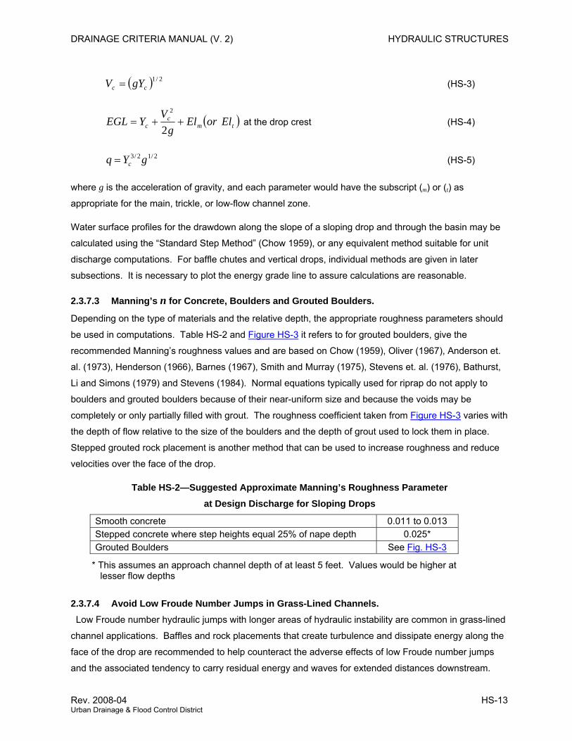
( ) 2/1cc gYV = (HS-3)
( tmc
c ElorElg
VYEGL ++=
2
2
) at the drop crest (HS-4)
2/12/3 gYq c= (HS-5)
where g is the acceleration of gravity, and each parameter would have the subscript (m) or (t) as
appropriate for the main, trickle, or low-flow channel zone.
Water surface profiles for the drawdown along the slope of a sloping drop and through the basin may be
calculated using the “Standard Step Method” (Chow 1959), or any equivalent method suitable for unit
discharge computations. For baffle chutes and vertical drops, individual methods are given in later
subsections. It is necessary to plot the energy grade line to assure calculations are reasonable.
2.3.7.3 Manning’s n for Concrete, Boulders and Grouted Boulders.
Depending on the type of materials and the relative depth, the appropriate roughness parameters should
be used in computations. Table HS-2 and Figure HS-3 it refers to for grouted boulders, give the
recommended Manning’s roughness values and are based on Chow (1959), Oliver (1967), Anderson et.
al. (1973), Henderson (1966), Barnes (1967), Smith and Murray (1975), Stevens et. al. (1976), Bathurst,
Li and Simons (1979) and Stevens (1984). Normal equations typically used for riprap do not apply to
boulders and grouted boulders because of their near-uniform size and because the voids may be
completely or only partially filled with grout. The roughness coefficient taken from Figure HS-3 varies with
the depth of flow relative to the size of the boulders and the depth of grout used to lock them in place.
Stepped grouted rock placement is another method that can be used to increase roughness and reduce
velocities over the face of the drop.
Table HS-2—Suggested Approximate Manning’s Roughness Parameter at Design Discharge for Sloping Drops
Smooth concrete 0.011 to 0.013 Stepped concrete where step heights equal 25% of nape depth 0.025* Grouted Boulders See Fig. HS-3
* This assumes an approach channel depth of at least 5 feet. Values would be higher at lesser flow depths
2.3.7.4 Avoid Low Froude Number Jumps in Grass-Lined Channels. Low Froude number hydraulic jumps with longer areas of hydraulic instability are common in grass-lined
channel applications. Baffles and rock placements that create turbulence and dissipate energy along the
face of the drop are recommended to help counteract the adverse effects of low Froude number jumps
and the associated tendency to carry residual energy and waves for extended distances downstream.
Rev. 2008-04 HS-13 Urban Drainage & Flood Control District
HYDRAULIC STRUCTURES DRAINAGE CRITERIA MANUAL (V. 2)
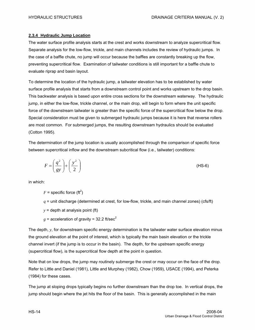
2.3.4 Hydraulic Jump Location The water surface profile analysis starts at the crest and works downstream to analyze supercritical flow.
Separate analysis for the low-flow, trickle, and main channels includes the review of hydraulic jumps. In
the case of a baffle chute, no jump will occur because the baffles are constantly breaking up the flow,
preventing supercritical flow. Examination of tailwater conditions is still important for a baffle chute to
evaluate riprap and basin layout.
To determine the location of the hydraulic jump, a tailwater elevation has to be established by water
surface profile analysis that starts from a downstream control point and works upstream to the drop basin.
This backwater analysis is based upon entire cross sections for the downstream waterway. The hydraulic
jump, in either the low-flow, trickle channel, or the main drop, will begin to form where the unit specific
force of the downstream tailwater is greater than the specific force of the supercritical flow below the drop.
Special consideration must be given to submerged hydraulic jumps because it is here that reverse rollers
are most common. For submerged jumps, the resulting downstream hydraulics should be evaluated
(Cotton 1995).
The determination of the jump location is usually accomplished through the comparison of specific force
between supercritical inflow and the downstream subcritical flow (i.e., tailwater) conditions:
⎟⎟⎠
⎞⎜⎜⎝
⎛+⎟⎟
⎠
⎞⎜⎜⎝
⎛=
2
22 ygyqF (HS-6)
in which:
F = specific force (ft2)
q = unit discharge (determined at crest, for low-flow, trickle, and main channel zones) (cfs/ft)
y = depth at analysis point (ft)
g = acceleration of gravity = 32.2 ft/sec2
The depth, y, for downstream specific energy determination is the tailwater water surface elevation minus
the ground elevation at the point of interest, which is typically the main basin elevation or the trickle
channel invert (if the jump is to occur in the basin). The depth, for the upstream specific energy
(supercritical flow), is the supercritical flow depth at the point in question.
Note that on low drops, the jump may routinely submerge the crest or may occur on the face of the drop.
Refer to Little and Daniel (1981), Little and Murphey (1982), Chow (1959), USACE (1994), and Peterka
(1984) for these cases.
The jump at sloping drops typically begins no further downstream than the drop toe. In vertical drops, the
jump should begin where the jet hits the floor of the basin. This is generally accomplished in the main
HS-14 2008-04 Urban Drainage & Flood Control District
DRAINAGE CRITERIA MANUAL (V. 2) HYDRAULIC STRUCTURES
drop zone by depressing the basin to a depth nearly as low as the downstream trickle channel elevation.
This will provide drainage for the basin.
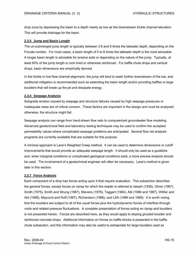
2.3.5 Jump and Basin Length The un-submerged jump length is typically between 3.6 and 6 times the tailwater depth, depending on the
Froude number. For most cases, a basin length of 5 to 6 times the tailwater depth is the most advisable.
A longer basin length is advisable for erosive soils or depending on the nature of the jump. Typically, at
least 60% of the jump length is rock lined or otherwise reinforced. For baffle chute drops and vertical
drops, basin dimensions are empirically derived.
In the trickle or low-flow channel alignment, the jump will tend to wash further downstream of the toe, and
additional mitigation is recommended such as extending the basin length and/or providing baffles or large
boulders that will break up the jet and dissipate energy.
2.3.6 Seepage Analysis Subgrade erosion caused by seepage and structure failures caused by high seepage pressures or
inadequate mass are of critical concern. These factors are important in the design and must be analyzed;
otherwise, the structure might fail.
Seepage analysis can range from hand-drawn flow nets to computerized groundwater flow modeling.
Advanced geotechnical field and laboratory testing techniques may be used to confirm the accepted
permeability values where complicated seepage problems are anticipated. Several flow net analysis
programs are currently available that are suitable for this purpose.
A minimal approach is Lane’s Weighted Creep method. It can be used to determine dimensions or cutoff
improvements that would provide an adequate seepage length. It should only be used as a guideline
and, when marginal conditions or complicated geological conditions exist, a more precise analysis should
be used. The involvement of a geotechnical engineer will often be necessary. Lane’s method is given
later in this section.
2.3.7 Force Analysis Each component of a drop has forces acting upon it that require evaluation. This subsection describes
the general forces, except forces on riprap for which the reader is referred to Isbash (1936), Oliver (1967),
Smith (1975), Smith and Strung (1967), Stevens (1976), Taggart (1984), Abt (1986 and 1987), WittIer and
Abt (1988), Maynord and Ruff (1987), Richardson (1988), and LSA (1986 and 1989). It is worth noting
that the boulders are subject to all of the usual forces plus the hydrodynamic forces of interflow through
voids and related pressure fluctuations. A complete presentation of forces acting on riprap and boulders
is not presented herein. Forces are described here, as they would apply to sloping grouted boulder and
reinforced concrete drops. Additional information on forces on baffle blocks is presented in the baffle
chute subsection, and this information may also be useful to extrapolate for large boulders used as
Rev. 2008-04 HS-15 Urban Drainage & Flood Control District
HYDRAULIC STRUCTURES DRAINAGE CRITERIA MANUAL (V. 2)
baffles in grouted boulder drops.
The various criteria for structural slab thicknesses given for each type of drop have generally taken these
forces into consideration. It is the user’s responsibility to determine the forces involved.
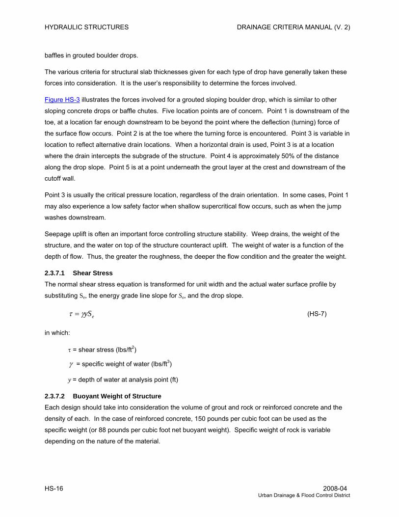
Figure HS-3 illustrates the forces involved for a grouted sloping boulder drop, which is similar to other
sloping concrete drops or baffle chutes. Five location points are of concern. Point 1 is downstream of the
toe, at a location far enough downstream to be beyond the point where the deflection (turning) force of
the surface flow occurs. Point 2 is at the toe where the turning force is encountered. Point 3 is variable in
location to reflect alternative drain locations. When a horizontal drain is used, Point 3 is at a location
where the drain intercepts the subgrade of the structure. Point 4 is approximately 50% of the distance
along the drop slope. Point 5 is at a point underneath the grout layer at the crest and downstream of the
cutoff wall.
Point 3 is usually the critical pressure location, regardless of the drain orientation. In some cases, Point 1
may also experience a low safety factor when shallow supercritical flow occurs, such as when the jump
washes downstream.
Seepage uplift is often an important force controlling structure stability. Weep drains, the weight of the
structure, and the water on top of the structure counteract uplift. The weight of water is a function of the
depth of flow. Thus, the greater the roughness, the deeper the flow condition and the greater the weight.
2.3.7.1 Shear Stress The normal shear stress equation is transformed for unit width and the actual water surface profile by
substituting Se, the energy grade line slope for So, and the drop slope.
eySγτ = (HS-7)
in which:
τ = shear stress (lbs/ft2)
γ = specific weight of water (lbs/ft3)
y = depth of water at analysis point (ft)
2.3.7.2 Buoyant Weight of Structure Each design should take into consideration the volume of grout and rock or reinforced concrete and the
density of each. In the case of reinforced concrete, 150 pounds per cubic foot can be used as the
specific weight (or 88 pounds per cubic foot net buoyant weight). Specific weight of rock is variable
depending on the nature of the material.
HS-16 2008-04 Urban Drainage & Flood Control District
DRAINAGE CRITERIA MANUAL (V. 2) HYDRAULIC STRUCTURES
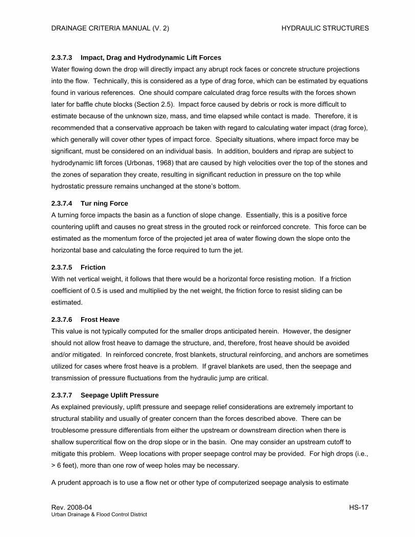
2.3.7.3 Impact, Drag and Hydrodynamic Lift Forces Water flowing down the drop will directly impact any abrupt rock faces or concrete structure projections
into the flow. Technically, this is considered as a type of drag force, which can be estimated by equations
found in various references. One should compare calculated drag force results with the forces shown
later for baffle chute blocks (Section 2.5). Impact force caused by debris or rock is more difficult to
estimate because of the unknown size, mass, and time elapsed while contact is made. Therefore, it is
recommended that a conservative approach be taken with regard to calculating water impact (drag force),
which generally will cover other types of impact force. Specialty situations, where impact force may be
significant, must be considered on an individual basis. In addition, boulders and riprap are subject to
hydrodynamic lift forces (Urbonas, 1968) that are caused by high velocities over the top of the stones and
the zones of separation they create, resulting in significant reduction in pressure on the top while
hydrostatic pressure remains unchanged at the stone’s bottom.
2.3.7.4 Tur ning Force A turning force impacts the basin as a function of slope change. Essentially, this is a positive force
countering uplift and causes no great stress in the grouted rock or reinforced concrete. This force can be
estimated as the momentum force of the projected jet area of water flowing down the slope onto the
horizontal base and calculating the force required to turn the jet.
2.3.7.5 Friction With net vertical weight, it follows that there would be a horizontal force resisting motion. If a friction
coefficient of 0.5 is used and multiplied by the net weight, the friction force to resist sliding can be
estimated.
2.3.7.6 Frost Heave This value is not typically computed for the smaller drops anticipated herein. However, the designer
should not allow frost heave to damage the structure, and, therefore, frost heave should be avoided
and/or mitigated. In reinforced concrete, frost blankets, structural reinforcing, and anchors are sometimes
utilized for cases where frost heave is a problem. If gravel blankets are used, then the seepage and
transmission of pressure fluctuations from the hydraulic jump are critical.
2.3.7.7 Seepage Uplift Pressure As explained previously, uplift pressure and seepage relief considerations are extremely important to
structural stability and usually of greater concern than the forces described above. There can be
troublesome pressure differentials from either the upstream or downstream direction when there is
shallow supercritical flow on the drop slope or in the basin. One may consider an upstream cutoff to
mitigate this problem. Weep locations with proper seepage control may be provided. For high drops (i.e.,
> 6 feet), more than one row of weep holes may be necessary.
A prudent approach is to use a flow net or other type of computerized seepage analysis to estimate
Rev. 2008-04 HS-17 Urban Drainage & Flood Control District
HYDRAULIC STRUCTURES DRAINAGE CRITERIA MANUAL (V. 2)
seepage pressures and flows under a structure.
2.3.7.8 Dynamic Pressure Fluctuations Laboratory testing (Toso 1986; Bowers and Toso 1988) has documented that the severe turbulence in a
hydraulic jump can pose special problems often ignored in hydraulic structures. This turbulence can
cause significant positive and negative pressure fluctuations along a structure.
A good example of the problem can be envisioned by a situation in which the entire sloping face of the
drop is underlain by a gravel seepage blanket. The gravel could be drained to the bottom of the basin or
other locations where the jump will occur. In such a case, the positive pressure fluctuations could be
transmitted directly to the area under the sloping face, which then could destabilize the structure since
there would not be sufficient weight of water over the structure in the area of shallow supercritical flow.
The key parameter is the coefficient of maximum pressure fluctuation, Cp-max, which is in terms of the
velocity head of the supercritical flow just upstream of the jump:
⎟⎟⎠
⎞⎜⎜⎝
⎛Δ
=−
gV
PCu
p
2
2max (HS-8)
in which:
PΔ = pressure deviation (fluctuation) from mean (ft)
uV = incident velocity (just upstream of jump) (ft/sec)
g = acceleration of gravity (ft/sec2)
Effectively, CP is a function of the Froude number of the supercritical flow. The parameter varies as a
function of X, which is the downstream distance from the beginning of the jump to the point of interest.
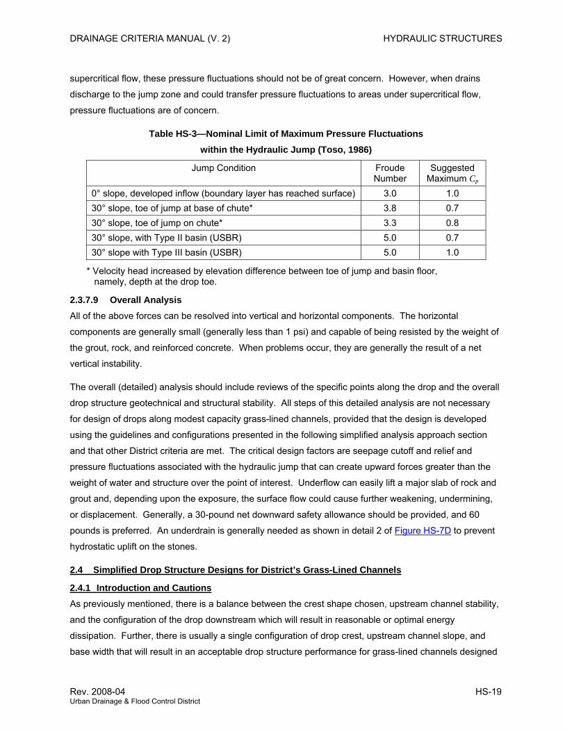
Table HS-3 presents recommended Cp-max positive pressure values for various configurations. When the
Froude number for the design case is lower than those indicated, the lowest value indicated should be
used (do not reduce on a linear relationship) for any quick calculations. The values can be tempered by
reviewing the Cp graphs, a few of which are given in Figures HS-4 through HS-6. Note that the graphs
are not maximum values but are the mean fluctuation of pressure. The standard deviation of the
fluctuations is also indicated, from which the recommended Cp-max values were derived.
Figure HS-4 illustrates positive and negative pressure fluctuations in the coefficient, Cp, with respect to the
location where the jump begins at the toe. Figure HS-5 presents the positive pressure fluctuation
coefficient where the jump begins on the face. Figure HS-6 illustrates how the pressure fluctuations vary
in a U.S. Bureau of Reclamation (USBR) Type II or III basin.
For the typical basin layouts given and where the drains are at the toe and connect directly to the
HS-18 2008-04 Urban Drainage & Flood Control District
DRAINAGE CRITERIA MANUAL (V. 2) HYDRAULIC STRUCTURES
supercritical flow, these pressure fluctuations should not be of great concern. However, when drains
discharge to the jump zone and could transfer pressure fluctuations to areas under supercritical flow,
pressure fluctuations are of concern.
Table HS-3—Nominal Limit of Maximum Pressure Fluctuations within the Hydraulic Jump (Toso, 1986)
Jump Condition Froude Number
Suggested Maximum Cp
0° slope, developed inflow (boundary layer has reached surface) 3.0 1.0 30° slope, toe of jump at base of chute* 3.8 0.7 30° slope, toe of jump on chute* 3.3 0.8 30° slope, with Type II basin (USBR) 5.0 0.7 30° slope with Type III basin (USBR) 5.0 1.0
* Velocity head increased by elevation difference between toe of jump and basin floor, namely, depth at the drop toe.
2.3.7.9 Overall Analysis All of the above forces can be resolved into vertical and horizontal components. The horizontal
components are generally small (generally less than 1 psi) and capable of being resisted by the weight of
the grout, rock, and reinforced concrete. When problems occur, they are generally the result of a net
vertical instability.
The overall (detailed) analysis should include reviews of the specific points along the drop and the overall
drop structure geotechnical and structural stability. All steps of this detailed analysis are not necessary
for design of drops along modest capacity grass-lined channels, provided that the design is developed
using the guidelines and configurations presented in the following simplified analysis approach section
and that other District criteria are met. The critical design factors are seepage cutoff and relief and
pressure fluctuations associated with the hydraulic jump that can create upward forces greater than the
weight of water and structure over the point of interest. Underflow can easily lift a major slab of rock and
grout and, depending upon the exposure, the surface flow could cause further weakening, undermining,
or displacement. Generally, a 30-pound net downward safety allowance should be provided, and 60
pounds is preferred. An underdrain is generally needed as shown in detail 2 of Figure HS-7D to prevent
hydrostatic uplift on the stones.
2.4 Simplified Drop Structure Designs for District’s Grass-Lined Channels
2.4.1 Introduction and Cautions As previously mentioned, there is a balance between the crest shape chosen, upstream channel stability,
and the configuration of the drop downstream which will result in reasonable or optimal energy
dissipation. Further, there is usually a single configuration of drop crest, upstream channel slope, and
base width that will result in an acceptable drop structure performance for grass-lined channels designed
Rev. 2008-04 HS-19 Urban Drainage & Flood Control District
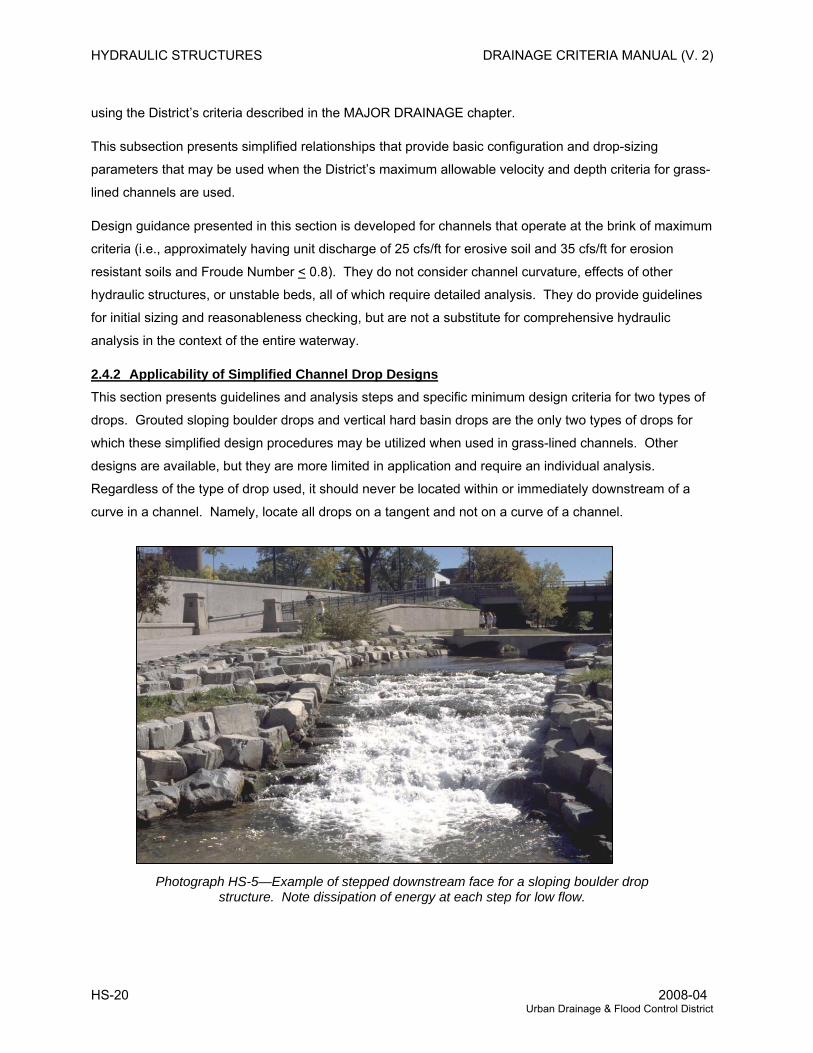
HYDRAULIC STRUCTURES DRAINAGE CRITERIA MANUAL (V. 2)
using the District’s criteria described in the MAJOR DRAINAGE chapter.
This subsection presents simplified relationships that provide basic configuration and drop-sizing
parameters that may be used when the District’s maximum allowable velocity and depth criteria for grass-
lined channels are used.
Design guidance presented in this section is developed for channels that operate at the brink of maximum
criteria (i.e., approximately having unit discharge of 25 cfs/ft for erosive soil and 35 cfs/ft for erosion
resistant soils and Froude Number < 0.8). They do not consider channel curvature, effects of other
hydraulic structures, or unstable beds, all of which require detailed analysis. They do provide guidelines
for initial sizing and reasonableness checking, but are not a substitute for comprehensive hydraulic
analysis in the context of the entire waterway.
2.4.2 Applicability of Simplified Channel Drop Designs This section presents guidelines and analysis steps and specific minimum design criteria for two types of
drops. Grouted sloping boulder drops and vertical hard basin drops are the only two types of drops for
which these simplified design procedures may be utilized when used in grass-lined channels. Other
designs are available, but they are more limited in application and require an individual analysis.
Regardless of the type of drop used, it should never be located within or immediately downstream of a
curve in a channel. Namely, locate all drops on a tangent and not on a curve of a channel.
Photograph HS-5—Example of stepped downstream face for a sloping boulder drop structure. Note dissipation of energy at each step for low flow.
HS-20 2008-04 Urban Drainage & Flood Control District
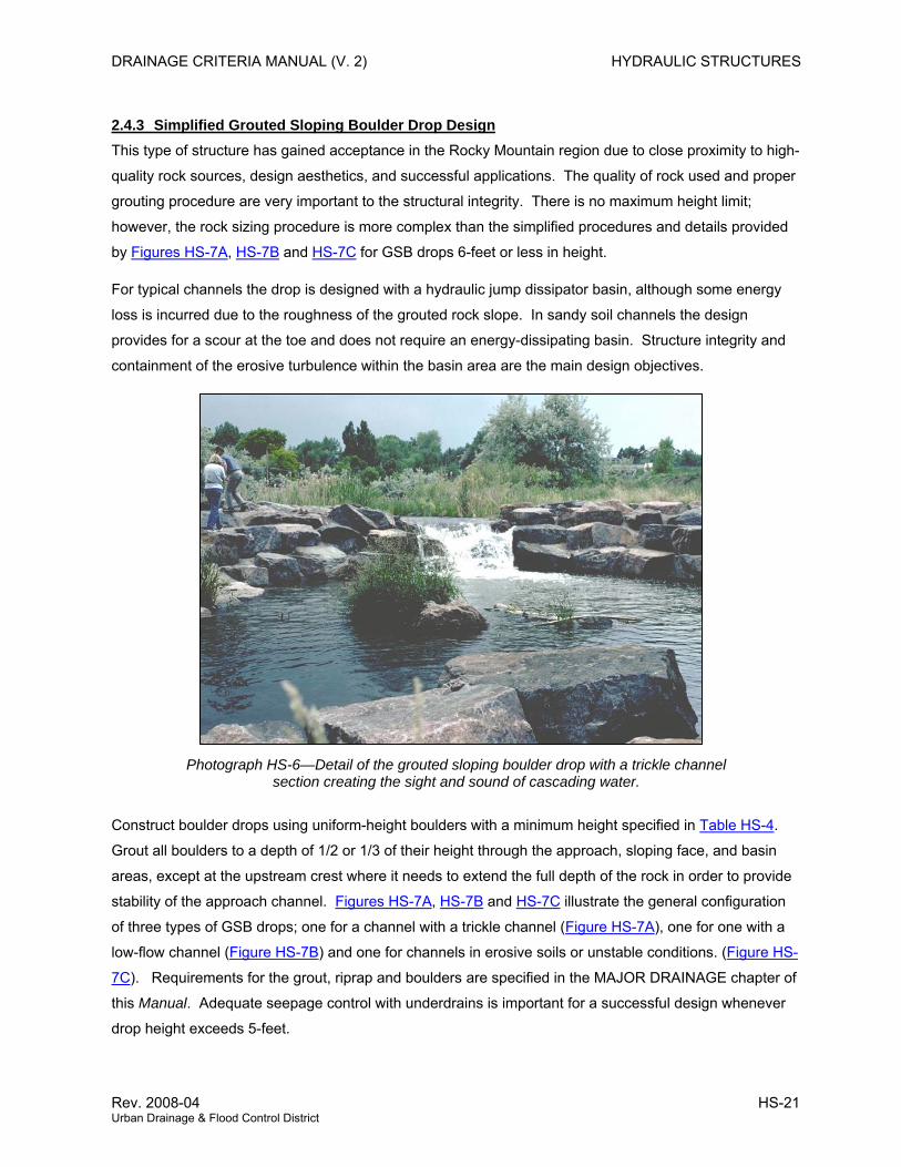
DRAINAGE CRITERIA MANUAL (V. 2) HYDRAULIC STRUCTURES
2.4.3 Simplified Grouted Sloping Boulder Drop Design This type of structure has gained acceptance in the Rocky Mountain region due to close proximity to high-
quality rock sources, design aesthetics, and successful applications. The quality of rock used and proper
grouting procedure are very important to the structural integrity. There is no maximum height limit;
however, the rock sizing procedure is more complex than the simplified procedures and details provided
by Figures HS-7A, HS-7B and HS-7C for GSB drops 6-feet or less in height.
For typical channels the drop is designed with a hydraulic jump dissipator basin, although some energy
loss is incurred due to the roughness of the grouted rock slope. In sandy soil channels the design
provides for a scour at the toe and does not require an energy-dissipating basin. Structure integrity and
containment of the erosive turbulence within the basin area are the main design objectives.
Photograph HS-6—Detail of the grouted sloping boulder drop with a trickle channel section creating the sight and sound of cascading water.
Construct boulder drops using uniform-height boulders with a minimum height specified in Table HS-4.
Grout all boulders to a depth of 1/2 or 1/3 of their height through the approach, sloping face, and basin
areas, except at the upstream crest where it needs to extend the full depth of the rock in order to provide
stability of the approach channel. Figures HS-7A, HS-7B and HS-7C illustrate the general configuration
of three types of GSB drops; one for a channel with a trickle channel (Figure HS-7A), one for one with a
low-flow channel (Figure HS-7B) and one for channels in erosive soils or unstable conditions. (Figure HS-
7C). Requirements for the grout, riprap and boulders are specified in the MAJOR DRAINAGE chapter of
this Manual. Adequate seepage control with underdrains is important for a successful design whenever
drop height exceeds 5-feet.
Rev. 2008-04 HS-21 Urban Drainage & Flood Control District
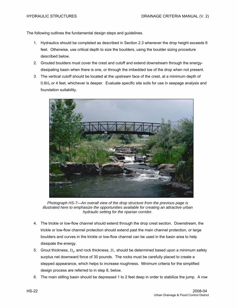
HYDRAULIC STRUCTURES DRAINAGE CRITERIA MANUAL (V. 2)
The following outlines the fundamental design steps and guidelines.
1. Hydraulics should be completed as described in Section 2.3 whenever the drop height exceeds 6
feet. Otherwise, use critical depth to size the boulders, using the boulder sizing procedure
described below.
2. Grouted boulders must cover the crest and cutoff and extend downstream through the energy-
dissipating basin when there is one, or through the imbedded toe of the drop when not present.
3. The vertical cutoff should be located at the upstream face of the crest, at a minimum depth of
0.8Hd or 4 feet, whichever is deeper. Evaluate specific site soils for use in seepage analysis and
foundation suitability.
Photograph HS-7—An overall view of the drop structure from the previous page is illustrated here to emphasize the opportunities available for creating an attractive urban
hydraulic setting for the riparian corridor.
4. The trickle or low-flow channel should extend through the drop crest section. Downstream, the
trickle or low-flow channel protection should extend past the main channel protection, or large
boulders and curves in the trickle or low-flow channel can be used in the basin area to help
dissipate the energy.
5. Grout thickness, Dg, and rock thickness, Dr, should be determined based upon a minimum safety
surplus net downward force of 30 pounds. The rocks must be carefully placed to create a
stepped appearance, which helps to increase roughness. Minimum criteria for the simplified
design process are referred to in step 8, below.
6. The main stilling basin should be depressed 1 to 2 feet deep in order to stabilize the jump. A row
HS-22 2008-04 Urban Drainage & Flood Control District
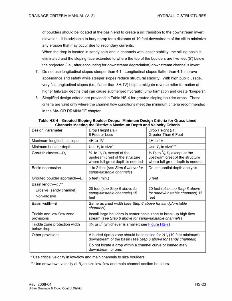
DRAINAGE CRITERIA MANUAL (V. 2) HYDRAULIC STRUCTURES
of boulders should be located at the basin end to create a sill transition to the downstream invert
elevation. It is advisable to bury riprap for a distance of 10 feet downstream of the sill to minimize
any erosion that may occur due to secondary currents.
When the drop is located in sandy soils and in channels with lesser stability, the stilling basin is
eliminated and the sloping face extended to where the top of the boulders are five feet (5’) below
the projected (i.e., after accounting for downstream degradation) downstream channel’s invert.
7. Do not use longitudinal slopes steeper than 4:1. Longitudinal slopes flatter than 4:1 improve
appearance and safety while steeper slopes reduce structural stability. With high public usage,
very flat longitudinal slopes (i.e., flatter than 8H:1V) help to mitigate reverse roller formation at
higher tailwater depths that can cause submerged hydraulic jump formation and create “keepers”.
8. Simplified design criteria are provided in Table HS-4 for grouted sloping boulder drops. These
criteria are valid only where the channel flow conditions meet the minimum criteria recommended
in the MAJOR DRAINAGE chapter.
Table HS-4—Grouted Sloping Boulder Drops: Minimum Design Criteria for Grass-Lined Channels Meeting the District’s Maximum Depth and Velocity Criteria
Design Parameter Drop Height (Hd) 6 Feet or Less
Drop Height (Hd) Greater Than 6 Feet
Maximum longitudinal slope 4H to 1V 4H to 1V Minimum boulder depth Use Vc to size* Use Vn to size*** Grout thickness—Dg ½ to 1/3 Dr except at the
upstream crest of the structure where full grout depth is needed
½ Dr to 1/3 Dr except at the upstream crest of the structure where full grout depth is needed
Basin depression 1 to 2 feet (see Step 6 above for sandy/unstable channels)
Do sequential depth analysis
Grouted boulder approach—La 5 feet (min.) 8 feet Basin length—Lb**
Erosive (sandy channel) Non-erosive
20 feet (see Step 6 above for sandy/unstable channels) 15 feet
20 feet (also see Step 6 above for sandy/unstable channels) 15 feet
Basin width—B Same as crest width (see Step 6 above for sandy/unstable channels)
Trickle and low-flow zone provisions
Install large boulders in center basin zone to break up high flow stream (see Step 6 above for sandy/unstable channels)
Trickle zone protection width below drop
3b1 or b2 (whichever is smaller; see Figure HS-7)
Other provisions A buried riprap zone should be installed for 2Hd (10 feet minimum) downstream of the basin (see Step 6 above for sandy channels) Do not locate a drop within a channel curve or immediately downstream of one.
* Use critical velocity in low-flow and main channels to size boulders. ** Use drawdown velocity at Hd to size low-flow and main channel section boulders.
Rev. 2008-04 HS-23 Urban Drainage & Flood Control District
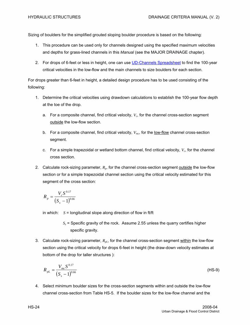
HYDRAULIC STRUCTURES DRAINAGE CRITERIA MANUAL (V. 2)
Sizing of boulders for the simplified grouted sloping boulder procedure is based on the following:
1. This procedure can be used only for channels designed using the specified maximum velocities
and depths for grass-lined channels in this Manual (see the MAJOR DRAINAGE chapter).
2. For drops of 6-feet or less in height, one can use UD-Channels Spreadsheet to find the 100-year
critical velocities in the low-flow and the main channels to size boulders for each section.
For drops greater than 6-feet in height, a detailed design procedure has to be used consisting of the
following:
1. Determine the critical velocities using drawdown calculations to establish the 100-year flow depth
at the toe of the drop.
a. For a composite channel, find critical velocity, Vc, for the channel cross-section segment
outside the low-flow section.
b. For a composite channel, find critical velocity, Vmc, for the low-flow channel cross-section
segment.
c. For a simple trapezoidal or wetland bottom channel, find critical velocity, Vc, for the channel
cross section.
2. Calculate rock-sizing parameter, Rp, for the channel cross-section segment outside the low-flow
section or for a simple trapezoidal channel section using the critical velocity estimated for this
segment of the cross section:
( ) 66.0
17.0
1−=
s
cp S
SVR
in which: S = longitudinal slope along direction of flow in ft/ft
Ss = Specific gravity of the rock. Assume 2.55 unless the quarry certifies higher
specific gravity.
3. Calculate rock-sizing parameter, RpL, for the channel cross-section segment within the low-flow
section using the critical velocity for drops 6-feet in height (the draw-down velocity estimates at
bottom of the drop for taller structures ):
( ) 66.0
17.0
1−=
s
mcpL S
SVR (HS-9)
4. Select minimum boulder sizes for the cross-section segments within and outside the low-flow
channel cross-section from Table HS-5. If the boulder sizes for the low-flow channel and the
HS-24 2008-04 Urban Drainage & Flood Control District
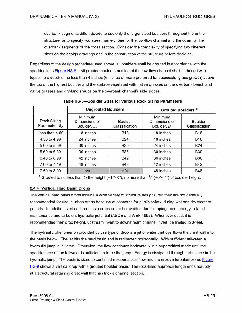
DRAINAGE CRITERIA MANUAL (V. 2) HYDRAULIC STRUCTURES
overbank segments differ, decide to use only the larger sized boulders throughout the entire
structure, or to specify two sizes, namely, one for the low-flow channel and the other for the
overbank segments of the cross section. Consider the complexity of specifying two different
sizes on the design drawings and in the construction of the structure before deciding.
Regardless of the design procedure used above, all boulders shall be grouted in accordance with the
specifications Figure HS-8. All grouted boulders outside of the low-flow channel shall be buried with
topsoil to a depth of no less than 4 inches (6 inches or more preferred for successful grass growth) above
the top of the highest boulder and the surface vegetated with native grasses on the overbank bench and
native grasses and dry-land shrubs on the overbank channel’s side slopes.
Table HS-5—Boulder Sizes for Various Rock Sizing Parameters
Ungrouted Boulders Grouted Boulders *
Rock Sizing Parameter, Rp
Minimum Dimensions of
Boulder, Dr Boulder
Classification
Minimum Dimensions of
Boulder, Dr Boulder
Classification
Less than 4.50 18 inches B18 18 inches B18 4.50 to 4.99 24 inches B24 18 inches B18 5.00 to 5.59 30 inches B30 24 inches B24 5.60 to 6.39 36 inches B36 30 inches B30 6.40 to 6.99 42 inches B42 36 inches B36 7.00 to 7.49 48 inches B48 42 inches B42 7.50 to 8.00 n/a n/a 48 inches B48
* Grouted to no less than ½ the height (+1”/- 0”), no more than 1/3 (+0”/- 1”) of boulder height.
2.4.4 Vertical Hard Basin Drops The vertical hard basin drops include a wide variety of structure designs, but they are not generally
recommended for use in urban areas because of concerns for public safety, during wet and dry weather
periods. In addition, vertical hard basin drops are to be avoided due to impingement energy, related
maintenance and turbulent hydraulic potential (ASCE and WEF 1992). Whenever used, it is
recommended their drop height, upstream invert to downstream channel invert, be limited to 3-feet.
The hydraulic phenomenon provided by this type of drop is a jet of water that overflows the crest wall into
the basin below. The jet hits the hard basin and is redirected horizontally. With sufficient tailwater, a
hydraulic jump is initiated. Otherwise, the flow continues horizontally in a supercritical mode until the
specific force of the tailwater is sufficient to force the jump. Energy is dissipated through turbulence in the
hydraulic jump. The basin is sized to contain the supercritical flow and the erosive turbulent zone. Figure
HS-9 shows a vertical drop with a grouted boulder basin. The rock-lined approach length ends abruptly
at a structural retaining crest wall that has trickle channel section.
Rev. 2008-04 HS-25 Urban Drainage & Flood Control District
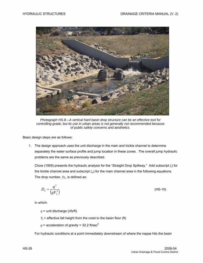
HYDRAULIC STRUCTURES DRAINAGE CRITERIA MANUAL (V. 2)
Photograph HS-8—A vertical hard basin drop structure can be an effective tool for controlling grade, but its use in urban areas is not generally not recommended because
of public safety concerns and aesthetics.
Basic design steps are as follows:
1. The design approach uses the unit discharge in the main and trickle channel to determine
separately the water surface profile and jump location in these zones. The overall jump hydraulic
problems are the same as previously described.
Chow (1959) presents the hydraulic analysis for the “Straight Drop Spillway.” Add subscript (t) for
the trickle channel area and subscript (m) for the main channel area in the following equations.
The drop number, Dn, is defined as:
( )3
2
fn gY
qD = (HS-10)
in which:
q = unit discharge (cfs/ft)
Yf = effective fall height from the crest to the basin floor (ft)
g = acceleration of gravity = 32.2 ft/sec2
For hydraulic conditions at a point immediately downstream of where the nappe hits the basin
HS-26 2008-04 Urban Drainage & Flood Control District
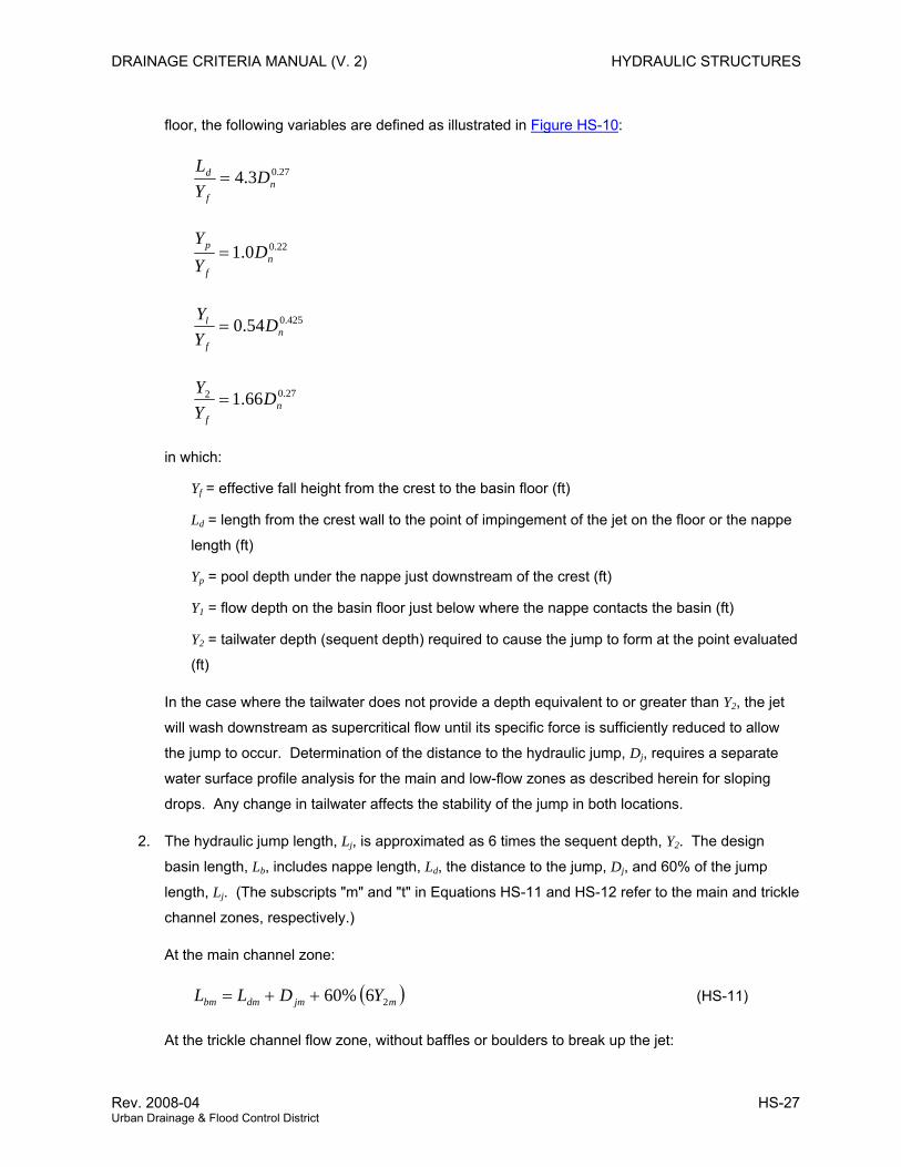
DRAINAGE CRITERIA MANUAL (V. 2) HYDRAULIC STRUCTURES
floor, the following variables are defined as illustrated in Figure HS-10:
27.03.4 nf
d DYL
=
22.00.1 nf
p DYY
=
425.054.0 nf
l DYY
=
27.02 66.1 nf
DYY
=
in which:
Yf = effective fall height from the crest to the basin floor (ft)
Ld = length from the crest wall to the point of impingement of the jet on the floor or the nappe
length (ft)
Yp = pool depth under the nappe just downstream of the crest (ft)
Y1 = flow depth on the basin floor just below where the nappe contacts the basin (ft)
Y2 = tailwater depth (sequent depth) required to cause the jump to form at the point evaluated
(ft)
In the case where the tailwater does not provide a depth equivalent to or greater than Y2, the jet
will wash downstream as supercritical flow until its specific force is sufficiently reduced to allow
the jump to occur. Determination of the distance to the hydraulic jump, Dj, requires a separate
water surface profile analysis for the main and low-flow zones as described herein for sloping
drops. Any change in tailwater affects the stability of the jump in both locations.
2. The hydraulic jump length, Lj, is approximated as 6 times the sequent depth, Y2. The design
basin length, Lb, includes nappe length, Ld, the distance to the jump, Dj, and 60% of the jump
length, Lj. (The subscripts "m" and "t" in Equations HS-11 and HS-12 refer to the main and trickle
channel zones, respectively.)
At the main channel zone:
( mjmdmbm YDLL 26%60++= ) (HS-11)
At the trickle channel flow zone, without baffles or boulders to break up the jet:
Rev. 2008-04 HS-27 Urban Drainage & Flood Control District
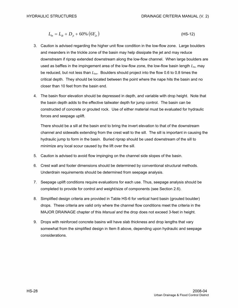
HYDRAULIC STRUCTURES DRAINAGE CRITERIA MANUAL (V. 2)
( tjtdtbt YDLL 26%60++= ) (HS-12)
3. Caution is advised regarding the higher unit flow condition in the low-flow zone. Large boulders
and meanders in the trickle zone of the basin may help dissipate the jet and may reduce
downstream if riprap extended downstream along the low-flow channel. When large boulders are
used as baffles in the impingement area of the low-flow zone, the low-flow basin length Lbt, may
be reduced, but not less than Lbm. Boulders should project into the flow 0.6 to 0.8 times the
critical depth. They should be located between the point where the nape hits the basin and no
closer than 10 feet from the basin end.
4. The basin floor elevation should be depressed in depth, and variable with drop height. Note that
the basin depth adds to the effective tailwater depth for jump control. The basin can be
constructed of concrete or grouted rock. Use of either material must be evaluated for hydraulic
forces and seepage uplift.
There should be a sill at the basin end to bring the invert elevation to that of the downstream
channel and sidewalls extending from the crest wall to the sill. The sill is important in causing the
hydraulic jump to form in the basin. Buried riprap should be used downstream of the sill to
minimize any local scour caused by the lift over the sill.
5. Caution is advised to avoid flow impinging on the channel side slopes of the basin.
6. Crest wall and footer dimensions should be determined by conventional structural methods.
Underdrain requirements should be determined from seepage analysis.
7. Seepage uplift conditions require evaluations for each use. Thus, seepage analysis should be
completed to provide for control and weight/size of components (see Section 2.6).
8. Simplified design criteria are provided in Table HS-6 for vertical hard basin (grouted boulder)
drops. These criteria are valid only where the channel flow conditions meet the criteria in the
MAJOR DRAINAGE chapter of this Manual and the drop does not exceed 3-feet in height.
9. Drops with reinforced concrete basins will have slab thickness and drop lengths that vary
somewhat from the simplified design in Item 8 above, depending upon hydraulic and seepage
considerations.
HS-28 2008-04 Urban Drainage & Flood Control District
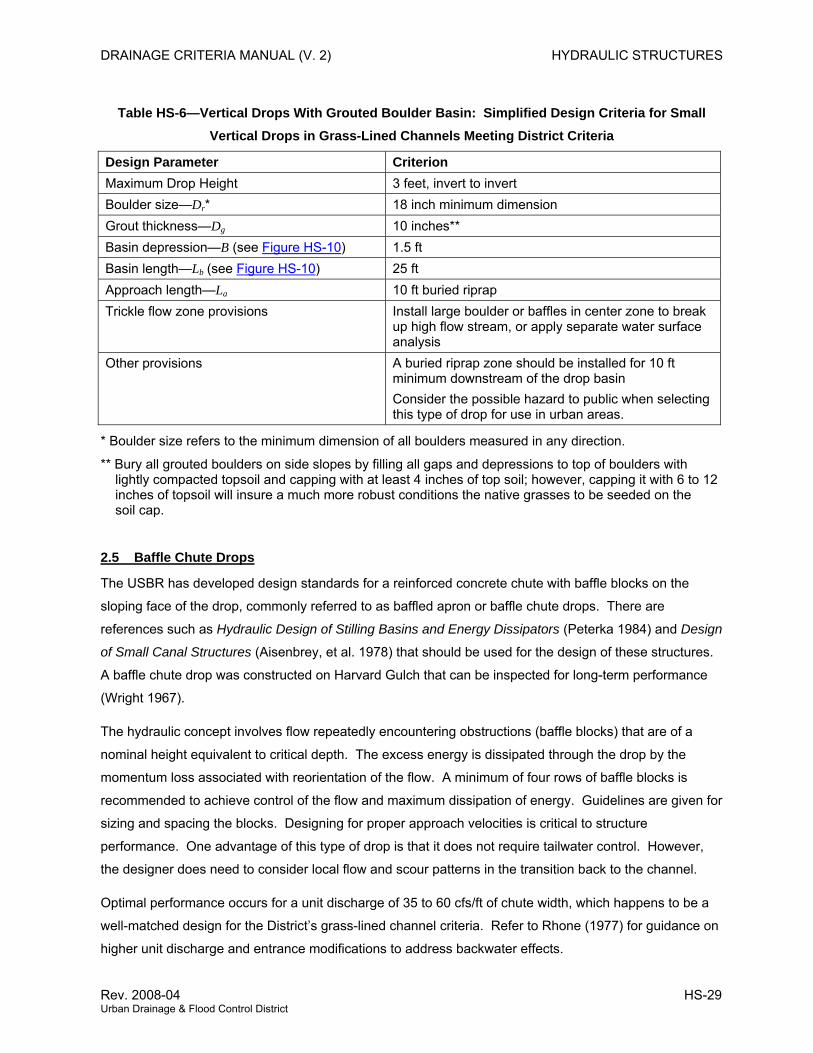
DRAINAGE CRITERIA MANUAL (V. 2) HYDRAULIC STRUCTURES
Table HS-6—Vertical Drops With Grouted Boulder Basin: Simplified Design Criteria for Small Vertical Drops in Grass-Lined Channels Meeting District Criteria
Design Parameter Criterion Maximum Drop Height 3 feet, invert to invert Boulder size—Dr* 18 inch minimum dimension Grout thickness—Dg 10 inches** Basin depression—B (see Figure HS-10) 1.5 ft Basin length—Lb (see Figure HS-10) 25 ft Approach length—La 10 ft buried riprap Trickle flow zone provisions Install large boulder or baffles in center zone to break
up high flow stream, or apply separate water surface analysis
Other provisions A buried riprap zone should be installed for 10 ft minimum downstream of the drop basin Consider the possible hazard to public when selecting this type of drop for use in urban areas.
* Boulder size refers to the minimum dimension of all boulders measured in any direction.
** Bury all grouted boulders on side slopes by filling all gaps and depressions to top of boulders with lightly compacted topsoil and capping with at least 4 inches of top soil; however, capping it with 6 to 12 inches of topsoil will insure a much more robust conditions the native grasses to be seeded on the soil cap.
2.5 Baffle Chute Drops
The USBR has developed design standards for a reinforced concrete chute with baffle blocks on the
sloping face of the drop, commonly referred to as baffled apron or baffle chute drops. There are
references such as Hydraulic Design of Stilling Basins and Energy Dissipators (Peterka 1984) and Design
of Small Canal Structures (Aisenbrey, et al. 1978) that should be used for the design of these structures.
A baffle chute drop was constructed on Harvard Gulch that can be inspected for long-term performance
(Wright 1967).
The hydraulic concept involves flow repeatedly encountering obstructions (baffle blocks) that are of a
nominal height equivalent to critical depth. The excess energy is dissipated through the drop by the
momentum loss associated with reorientation of the flow. A minimum of four rows of baffle blocks is
recommended to achieve control of the flow and maximum dissipation of energy. Guidelines are given for
sizing and spacing the blocks. Designing for proper approach velocities is critical to structure
performance. One advantage of this type of drop is that it does not require tailwater control. However,
the designer does need to consider local flow and scour patterns in the transition back to the channel.
Optimal performance occurs for a unit discharge of 35 to 60 cfs/ft of chute width, which happens to be a
well-matched design for the District’s grass-lined channel criteria. Refer to Rhone (1977) for guidance on
higher unit discharge and entrance modifications to address backwater effects.
Rev. 2008-04 HS-29 Urban Drainage & Flood Control District
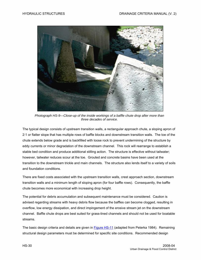
HYDRAULIC STRUCTURES DRAINAGE CRITERIA MANUAL (V. 2)
Photograph HS-9—Close-up of the inside workings of a baffle chute drop after more than three decades of service.
The typical design consists of upstream transition walls, a rectangular approach chute, a sloping apron of
2:1 or flatter slope that has multiple rows of baffle blocks and downstream transition walls. The toe of the
chute extends below grade and is backfilled with loose rock to prevent undermining of the structure by
eddy currents or minor degradation of the downstream channel. This rock will rearrange to establish a
stable bed condition and produce additional stilling action. The structure is effective without tailwater;
however, tailwater reduces scour at the toe. Grouted and concrete basins have been used at the
transition to the downstream trickle and main channels. The structure also lends itself to a variety of soils
and foundation conditions.
There are fixed costs associated with the upstream transition walls, crest approach section, downstream
transition walls and a minimum length of sloping apron (for four baffle rows). Consequently, the baffle
chute becomes more economical with increasing drop height.
The potential for debris accumulation and subsequent maintenance must be considered. Caution is
advised regarding streams with heavy debris flow because the baffles can become clogged, resulting in
overflow, low energy dissipation, and direct impingement of the erosive stream jet on the downstream
channel. Baffle chute drops are best suited for grass-lined channels and should not be used for boatable
streams.
The basic design criteria and details are given in Figure HS-11 (adapted from Peterka 1984). Remaining
structural design parameters must be determined for specific site conditions. Recommended design
HS-30 2008-04 Urban Drainage & Flood Control District
DRAINAGE CRITERIA MANUAL (V. 2) HYDRAULIC STRUCTURES
procedures are as follows:
1. Determine the maximum inflow rate and the design unit discharge, WQq = .
2. An upstream channel transition section with vertical wingwalls constructed 45 degrees to the flow
direction causes flow approaching the rectangular chute section to contract. It is also feasible to
use walls constructed at 90 degrees to the flow direction. In either configuration, it is important to
analyze the approach hydraulics and water surface profile. Often, the effective flow width at the
critical cross section is narrower than the width of the chute opening due to flow separation at the
corners of the abutment (see Section 5.0).
3. The entrance transition should be followed by a rectangular flow alignment apron, typically 5 feet
in length. The upstream approach channel velocity, V, should be as low as practical and less
than critical velocity at the control section of the crest. Figure HS-11 gives the USBR-
recommended chute entrance velocity. In a typical grass-lined channel, the entrance transition to
the rectangular chute section will produce the desired upstream channel velocity reduction. The
chute elevation (shown in Figure HS-11) should only be above the channel elevation when
approach velocities cannot be controlled by the transition. Extra measures to prevent upstream
aggradation are required with the raised crest configuration.
4. Normally, the baffles should be sized at height, H, equal to 0.8 times critical depth at peak flow.
The chute face slope should be 2:1 for most cases but may be reduced for low drops or where a
flatter slope is desirable. For unit discharge applications greater than 60 cfs/ft, the baffle height
may be based on two-thirds of the peak flow; however, the chute sidewalls should be designed
for peak flow (see Step 8 below).
Baffle block widths and spaces should equal approximately 1.5H but not less than H. Other baffle
block dimensions are not critical hydraulically. The spacing between the rows of baffle block
should be H times the slope ratio. For example, a 2:1 slope makes the row spacing equal to 2H
parallel to the chute floor. The baffle blocks should be constructed with the upstream face normal
to the chute floor.
5. Four rows of baffle blocks are required to establish full control of the flow. At least 1½ rows of
baffles should be buried in riprap where the chute extends below the downstream channel grade.
Rock protection, assumed here as Type M riprap, should continue from the chute outlet to a
minimum distance of approximately 4H at a riprap layer depth of 2.0 feet to prevent eddy currents
from undermining the walls. Additional rows of baffles may need to be buried below grade to
allow for downstream channel degradation. Determine if the downstream channel grade has
been stabilized to determine how many rows of baffles may need to be buried.
Rev. 2008-04 HS-31 Urban Drainage & Flood Control District
HYDRAULIC STRUCTURES DRAINAGE CRITERIA MANUAL (V. 2)
6. The baffle chute wall height (measured normal to the floor slope) should be 2.4 times the critical
depth based on peak discharge. The wall height will contain the main flow and most of the
splash. The designer of the area behind the wall should consider that some splash may occur,
but extensive protection measures are not required.
7. Determine upstream transition and apron sidewall height as required by backwater analysis.
Lower basin wingwalls generally should be constructed normal to the chute sidewalls at the chute
outlet to prevent eddy current erosion at the drop toe. These transition walls should be of a
height equal to the channel normal depth in the downstream channel plus 1 foot and length
sufficient to inhibit eddy current erosion.
8. The trickle flow channel should be maintained through the entrance transition apron, approach,
and crest sections. It may be routed between the first row of baffle piers. The trickle channel
should start again at the basin rock zone that should be slightly depressed and then graded up to
transition into the downstream channel to focus the low flows into the trickle channel. Figure HS-
12 illustrates one method of designing the trickle channel through the crest.
9. The conventional design shown in Figure HS-11 results in the top elevation of the baffles being
higher than the crest, which causes a backwater effect upstream. Figure HS-12 may be used to
estimate the extent of the effect and to determine corrective measures such as increasing the
upstream freeboard or widening the chute. Note that blocks projecting above the crest will tend
to produce upstream sediment aggradation. Channel aggradation can be minimized by the trickle
channel treatment suggested in Step 8.
Another means of alleviating these problems is by using the Fujimoto entrance developed by the
USBR and illustrated in Figure HS-12. The upper rows of baffles are moved one row increment
downstream. The important advantage of this entrance is that there is not a backwater effect of
the baffles. The serrated treatment of the modified crest begins disrupting the flow entering the
chute without increasing the headwater. More importantly, this configuration provides a level
crest control. The designer may either bring the invert of the upstream trickle channel into this
crest elevation, widening the trickle channel as it approaches the crest, or he or she may have a
lower trickle channel and bring it through the serrated crest similar to Step 8.
10. Concrete walls and footer dimensions should be determined by conventional structural methods.
Cutoffs and underdrain requirements should be determined by seepage analysis discussed
earlier in this chapter.
11. The hydraulic impact forces on the baffles should be determined to allow the structural engineer
to size adequate reinforcing steel. Figure HS-12 may be used as a guideline. The structural
engineer should apply a conservative safety factor.
HS-32 2008-04 Urban Drainage & Flood Control District
DRAINAGE CRITERIA MANUAL (V. 2) HYDRAULIC STRUCTURES
2.6 Seepage Control
2.6.1 Seepage Analysis Methods The preferred deterministic methodology for seepage analysis is the use of manual and computerized
flow net analyses. It is used to quantify groundwater flows, pressures, and critical gradients under
hydraulic structures. Flow net analysis can quantify the effects of multiple strata of different soil media
and complex geometries and situations. Full decryption of flow net analysis is beyond the scope of this
Manual and the user is referred to Cedergren (1967), USBR (1987) and Taylor (1967) for more
information and instruction in the use of flow net analysis techniques.
At an absolute minimum and as a first order of estimation, Lane’s Weighted Creep Method (CWM) can be
used to identify probable seepage problems, evaluate the need for control measures, and roughly
estimate uplift forces. It is not as definitive as the above-mentioned flow net analysis. The CWM
technique was originally proposed by E.W. Lane in 1935. This method has been deleted, however, in the
1987 revision of Design of Small Dams (USBR 1987), possibly indicating greater use of flow net and
computer modeling methods or for other reasons that we do not know about. Although Lane’s method is
relatively well founded, it should be used as a guideline, and when marginal conditions or complicated
geological conditions exist, the more sophisticated flow-net analysis should be used. The essential
elements of Lane’s method are as follows:
1. The weighted-creep distance through a cross section of a structure is the sum of the vertical
creep distances, Lv (along contact surfaces steeper than 45 degrees), plus one-third of the
horizontal creep distances, LH (along contact surfaces less than 45 degrees).
2. The weighted-creep head ratio is defined as:
S
VH
W H
LL
C⎟⎠⎞
⎜⎝⎛ +
=3
(HS-13)
in which:
CW = creep ratio
HS = differential head between analysis points (ft)
3. Reverse filter drains, weep holes, and pipe drains help to reduce seepage problems, and
recommended creep head ratios may be reduced as much as 10% if they are used.
4. In the case where two vertical cutoffs are used, then Equation HS-13 should be used along with
Equation HS-14 to check the short path between the bottom of the vertical cutoffs.
Rev. 2008-04 HS-33 Urban Drainage & Flood Control District
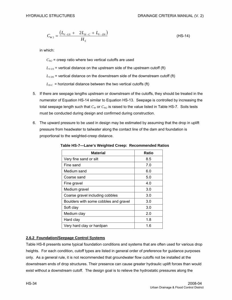
HYDRAULIC STRUCTURES DRAINAGE CRITERIA MANUAL (V. 2)
( )S
DSVCHUSVW H
LLLC −−− ++=
22 (HS-14)
in which:
CW2 = creep ratio where two vertical cutoffs are used
LV-US = vertical distance on the upstream side of the upstream cutoff (ft)
LV-DS = vertical distance on the downstream side of the downstream cutoff (ft)
LH-C = horizontal distance between the two vertical cutoffs (ft)
5. If there are seepage lengths upstream or downstream of the cutoffs, they should be treated in the
numerator of Equation HS-14 similar to Equation HS-13. Seepage is controlled by increasing the
total seepage length such that CW or CW2 is raised to the value listed in Table HS-7. Soils tests
must be conducted during design and confirmed during construction.
6. The upward pressure to be used in design may be estimated by assuming that the drop in uplift
pressure from headwater to tailwater along the contact line of the dam and foundation is
proportional to the weighted-creep distance.
Table HS-7—Lane’s Weighted Creep: Recommended Ratios
Material Ratio Very fine sand or silt 8.5 Fine sand 7.0 Medium sand 6.0 Coarse sand 5.0 Fine gravel 4.0 Medium gravel 3.0 Coarse gravel including cobbles 3.0 Boulders with some cobbles and gravel 3.0 Soft clay 3.0 Medium clay 2.0 Hard clay 1.8 Very hard clay or hardpan 1.6
2.6.2 Foundation/Seepage Control Systems Table HS-8 presents some typical foundation conditions and systems that are often used for various drop
heights. For each condition, cutoff types are listed in general order of preference for guidance purposes
only. As a general rule, it is not recommended that groundwater flow cutoffs not be installed at the
downstream ends of drop structures. Their presence can cause greater hydraulic uplift forces than would
exist without a downstream cutoff. The design goal is to relieve the hydrostatic pressures along the
HS-34 2008-04 Urban Drainage & Flood Control District

DRAINAGE CRITERIA MANUAL (V. 2) HYDRAULIC STRUCTURES
structure and not to block the groundwater flow and cause higher pressures to build up.
The hydraulic engineer must calculate hydraulic loadings that can occur for a variety of conditions such
as during construction, during dominant low flows, during flood flows, during design flows and other
critical loading scenarios. The soils/foundation engineer combines this information with the on-site soils
information to determine foundation requirements. Both engineers should work with a structural engineer
to establish final loading diagrams and in selection and sizing of structural components.
Table HS-8—General Cutoff Technique Suitability
Drop Height (ft) Soil Conditions 2 4 8 12 Sands and gravel over bedrock with sufficient depth of material to provide support—groundwater prevalent
SP1 CTc CTf
SP1 CTc/ST CTf/CTI
Sp/SwB1 ST
Sp/SwB1 ST
Sands and gravel with shallow depth to bedrock—groundwater prevalent
CTc CW SP2
CTc/ST CW SP2
ST CW SP2
ST CW SwB2
Sands and gravel with large depths to bedrock—groundwater prevalent
SP CTc
SP CTc/ST
SP ST
SP/SwB ST
Sands and gravel, no groundwater, or water table normally below requirement (for variation caused by depth to bedrock, see first case)
SP CTf/CTl CW
SP CTl CW
SP CTl
SP/SwB CTl
CTc CT CT CT CW Reduce length for difficult backfill
conditions CTl/CTf Only for local seepage zones/silts
Clay (and silts)—medium to hard
ST Expensive—for special problems Clays (and silts)—soft to medium with lenses of permeable material—groundwater present
CP CTc
SP CTc
SP CTc/ST
SP/SwB ST
Clay (and silts)—soft to medium with lenses of permeable material (may be moist but not significant groundwater source)
SP CTc CTf CW
SP CTc CTl CW
SP CTc/ST CTl CW
SP/SwB ST CTl CW
1 Consider scour in sheet pile support. 2 Excavate into bedrock and set into concrete. Legend:
SP Sheet pile SwB Sheet pile with bracing and extra measures CTc Cutoff trench backfilled with concrete ST Slurry trench; similar to CTc, but trench walls are supported with slurry and then later replaced
with concrete or additives that provide cutoff CW Cutoff wall; conventional wall, possibly with footer, backfilled; note that the effective seepage
length should generally be decreased because of backfill CTl Cutoff trench with synthetic liner and fill CTf Cutoff trench with clay fill
Rev. 2008-04 HS-35 Urban Drainage & Flood Control District
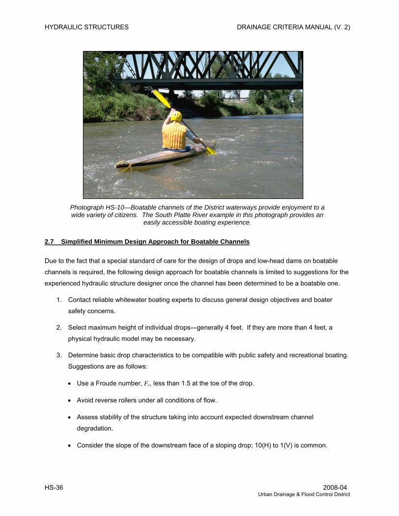
HYDRAULIC STRUCTURES DRAINAGE CRITERIA MANUAL (V. 2)
Photograph HS-10—Boatable channels of the District waterways provide enjoyment to a wide variety of citizens. The South Platte River example in this photograph provides an
easily accessible boating experience.
2.7 Simplified Minimum Design Approach for Boatable Channels
Due to the fact that a special standard of care for the design of drops and low-head dams on boatable
channels is required, the following design approach for boatable channels is limited to suggestions for the
experienced hydraulic structure designer once the channel has been determined to be a boatable one.
1. Contact reliable whitewater boating experts to discuss general design objectives and boater
safety concerns.
2. Select maximum height of individual drops—generally 4 feet. If they are more than 4 feet, a
physical hydraulic model may be necessary.
3. Determine basic drop characteristics to be compatible with public safety and recreational boating.
Suggestions are as follows:
• Use a Froude number, Fr, less than 1.5 at the toe of the drop.
• Avoid reverse rollers under all conditions of flow.
• Assess stability of the structure taking into account expected downstream channel
degradation.
• Consider the slope of the downstream face of a sloping drop; 10(H) to 1(V) is common.
HS-36 2008-04 Urban Drainage & Flood Control District
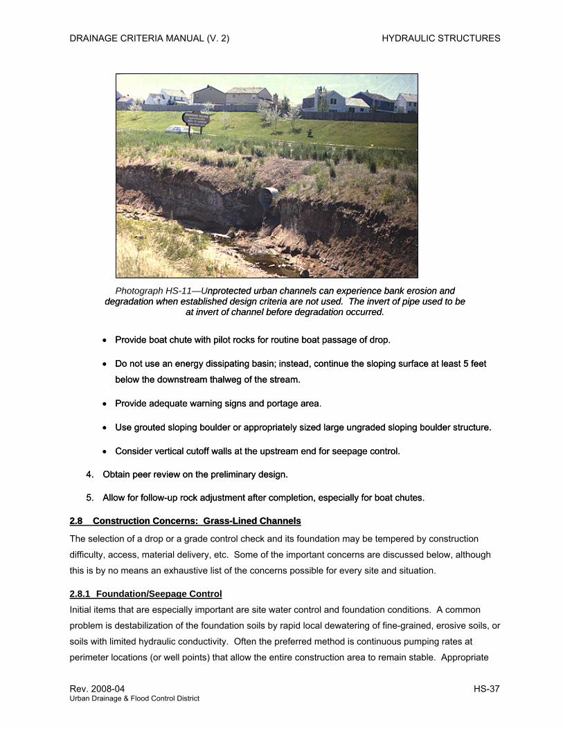
DRAINAGE CRITERIA MANUAL (V. 2) HYDRAULIC STRUCTURES
Photograph HS-11—Unprotected urban channels can experience bank erosion and degradation when established design criteria are not used. The invert of pipe used to be
at invert of channel before degradation occurred.
nprotected urban channels can experience bank erosion and degradation when established design criteria are not used. The invert of pipe used to be
at invert of channel before degradation occurred.
• Provide boat chute with pilot rocks for routine boat passage of drop. • Provide boat chute with pilot rocks for routine boat passage of drop.
• Do not use an energy dissipating basin; instead, continue the sloping surface at least 5 feet
below the downstream thalweg of the stream.
• Do not use an energy dissipating basin; instead, continue the sloping surface at least 5 feet
below the downstream thalweg of the stream.
• Provide adequate warning signs and portage area. • Provide adequate warning signs and portage area.
• Use grouted sloping boulder or appropriately sized large ungraded sloping boulder structure. • Use grouted sloping boulder or appropriately sized large ungraded sloping boulder structure.
• Consider vertical cutoff walls at the upstream end for seepage control. • Consider vertical cutoff walls at the upstream end for seepage control.
4. Obtain peer review on the preliminary design. 4. Obtain peer review on the preliminary design.
5. Allow for follow-up rock adjustment after completion, especially for boat chutes. 5. Allow for follow-up rock adjustment after completion, especially for boat chutes.
2.8 Construction Concerns: Grass-Lined Channels2.8 Construction Concerns: Grass-Lined Channels
The selection of a drop or a grade control check and its foundation may be tempered by construction
difficulty, access, material delivery, etc. Some of the important concerns are discussed below, although
this is by no means an exhaustive list of the concerns possible for every site and situation.
2.8.1 Foundation/Seepage Control Initial items that are especially important are site water control and foundation conditions. A common
problem is destabilization of the foundation soils by rapid local dewatering of fine-grained, erosive soils, or
soils with limited hydraulic conductivity. Often the preferred method is continuous pumping rates at
perimeter locations (or well points) that allow the entire construction area to remain stable. Appropriate
Rev. 2008-04 HS-37 Urban Drainage & Flood Control District
HYDRAULIC STRUCTURES DRAINAGE CRITERIA MANUAL (V. 2)
water control techniques for use during construction of a drop structure should be presented to the
contractor. Diversion berms should be designed with planned berm failure points to avoid flooding of
drop-structure sites during construction.
The actual subgrade condition with respect to seepage control assumptions must be inspected and field
verified. The engineer who established the design assumptions and calculated the required cutoffs
should inspect the cutoff for each drop and adjust the cutoff for the actual conditions encountered. For
example, if the inspection of a cutoff trench reveals a sandy substrate rather than clay, then the cutoff
trench may need to be deepened, or a different cutoff type may need to be implemented. Obviously, soil
testing is an advisable precaution to minimize changes and avoid failures.
2.8.2 Baffle Chute Construction There are numerous steps necessary in the construction of a baffle chute, but a contractor usually easily
controls them. For quality control and inspection there are consistent, measurable, and repeatable
standards to apply.
Baffle chutes are highly successful as far as hydraulic performance is concerned and are straightforward
to construct. Steel, formwork, concrete placement and finish, and backfill generally require periodic
inspection. Potential problems include foundation integrity, riprap quality control, water control, and the
finish work with regard to architectural and landscape treatments. Formwork, form ties, and seal coatings
can leave a poor appearance if not done properly.
2.8.3 Vertical Hard Basin Construction Foundation and seepage concerns are critical with regard to the vertical wall. Poor construction and
seepage control can result in sudden failure. The use of caissons or piles can mitigate this effect. Put in
comparative terms with the baffle chute, seepage problems can result in displacement of the vertical wall
with no warning, where the box-like structure of the baffle chute may experience some movement or
cracking, but not total failure, and thus allow time for repairs.
The quality control concerns and measures for vertical basins are the same as for baffle chutes. The
subsoil condition beneath the basin is important to insure that the stilling basin concrete or grouted rock
bottom is stable against uplift pressures.
2.8.4 Sloping Grouted Boulder Construction The sloping grouted boulder drops require significant construction control efforts in the field. Seepage
analysis is required to determine a compatible combination of cutoff depth, location of weep and toe
drains, and the thickness of grouted rock layer. The greatest danger lies with a “sugar-coated” grout job,
where the grout does not penetrate the voids fully between the rock and the subgrade and leaves voids
below the grout that act as a direct piping route for water, guaranteeing early failure.
Individual boulders should be larger in diameter than the grout layer so that the contractor and the
HS-38 2008-04 Urban Drainage & Flood Control District
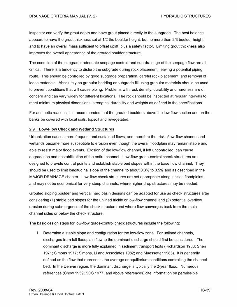
DRAINAGE CRITERIA MANUAL (V. 2) HYDRAULIC STRUCTURES
inspector can verify the grout depth and have grout placed directly to the subgrade. The best balance
appears to have the grout thickness set at 1/2 the boulder height, but no more than 2/3 boulder height,
and to have an overall mass sufficient to offset uplift, plus a safety factor. Limiting grout thickness also
improves the overall appearance of the grouted boulder structure.
The condition of the subgrade, adequate seepage control, and sub-drainage of the seepage flow are all
critical. There is a tendency to disturb the subgrade during rock placement, leaving a potential piping
route. This should be controlled by good subgrade preparation, careful rock placement, and removal of
loose materials. Absolutely no granular bedding or subgrade fill using granular materials should be used
to prevent conditions that will cause piping. Problems with rock density, durability and hardness are of
concern and can vary widely for different locations. The rock should be inspected at regular intervals to
meet minimum physical dimensions, strengths, durability and weights as defined in the specifications.
For aesthetic reasons, it is recommended that the grouted boulders above the low flow section and on the
banks be covered with local soils, topsoil and revegetated.
2.9 Low-Flow Check and Wetland Structures
Urbanization causes more frequent and sustained flows, and therefore the trickle/low-flow channel and
wetlands become more susceptible to erosion even though the overall floodplain may remain stable and
able to resist major flood events. Erosion of the low-flow channel, if left uncontrolled, can cause
degradation and destabilization of the entire channel. Low-flow grade-control check structures are
designed to provide control points and establish stable bed slopes within the base flow channel. They
should be used to limit longitudinal slope of the channel to about 0.3% to 0.5% and as described in the
MAJOR DRAINAGE chapter. Low-flow check structures are not appropriate along incised floodplains
and may not be economical for very steep channels, where higher drop structures may be needed.
Grouted sloping boulder and vertical hard basin designs can be adapted for use as check structures after
considering (1) stable bed slopes for the unlined trickle or low-flow channel and (2) potential overflow
erosion during submergence of the check structure and where flow converges back from the main
channel sides or below the check structure.
The basic design steps for low-flow grade-control check structures include the following:
1. Determine a stable slope and configuration for the low-flow zone. For unlined channels,
discharges from full floodplain flow to the dominant discharge should first be considered. The
dominant discharge is more fully explained in sediment transport texts (Richardson 1988; Shen
1971; Simons 1977; Simons, Li and Associates 1982; and Muessetter 1983). It is generally
defined as the flow that represents the average or equilibrium conditions controlling the channel
bed. In the Denver region, the dominant discharge is typically the 2-year flood. Numerous
references (Chow 1959; SCS 1977; and above references) cite information on permissible
Rev. 2008-04 HS-39 Urban Drainage & Flood Control District

HYDRAULIC STRUCTURES DRAINAGE CRITERIA MANUAL (V. 2)
velocities. The range of stable longitudinal slopes for non-rock lined major drainageways in the
Denver area is between 0.003 ft/t and 0.005 ft/ft. Two exceptions to this range exist, one is for
larger streams and the South Platte River, where it can be much flatter, and the other is for steep
waterways with small tributary catchments of relatively low imperviousness, where the final stable
slopes can be steeper.
2. The configuration of the low-flow zone and number and placement of the check structures must
be reviewed. A good rule is to have the check structures spaced so the drop does not exceed
3-feet after the downstream channel has degraded to the projected stable longitudinal slope.
One type of check structure that can be used to stabilize low-flow channels within relatively stable
channels is the control check (see Figure HS-13a and Figure HS-13b). This type of a check structure can
be constructed by filling an excavated narrow trench (12’ minimum) with concrete if soil and groundwater
conditions permit trenching to a depth of 6 feet, or by driving a concrete capped sheet piles to 10 foot
depth when trenching is not possible.
Extend the cutoff walls into the main channel banks a minimum of 10 feet and make sure it rises
sufficiently to contain the 5- to 10-year flow (depending on local criteria), but no less than 2-feet above the
approach channel (outside the trickle flow section) to avoid side cutting.
Wetland channel check structures will typically do not have a trickle channel. When building check
structures for wetland bottom channels, place riprap downstream of the cutoff wall to dissipate the kinetic
energy when downstream backwater is low so as to avoid deep scour hole downstream.
HS-40 2008-04 Urban Drainage & Flood Control District
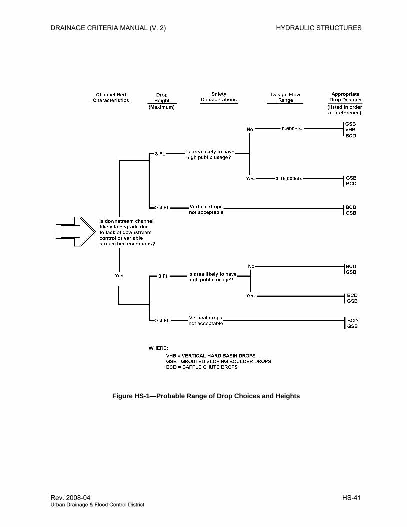
DRAINAGE CRITERIA MANUAL (V. 2) HYDRAULIC STRUCTURES
Figure HS-1—Probable Range of Drop Choices and Heights
Rev. 2008-04 HS-41 Urban Drainage & Flood Control District
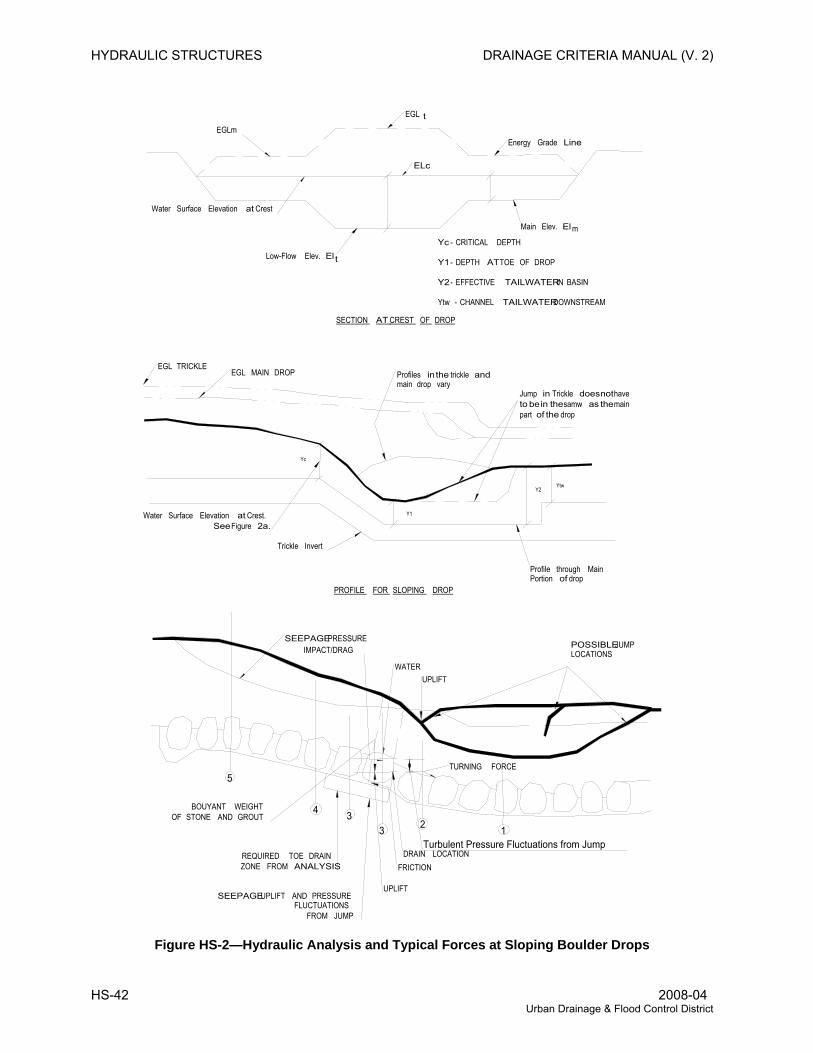
HYDRAULIC STRUCTURES DRAINAGE CRITERIA MANUAL (V. 2)
EGL t
Energy Grade LineEGLm
Water Surface Elevation at Crest
ELc
Low-Flow Elev. El
Main Elev. El
t
m
SECTION AT CREST OF DROP
Yc - CRITICAL DEPTH
Y1 - DEPTH AT TOE OF DROP
Y2 - EFFECTIVE TAILWATER IN BASIN
Ytw - CHANNEL TAILWATER DOWNSTREAM
EGL TRICKLEEGL MAIN DROP
Trickle Invert
Profile through Main Portion of drop
Yc
Water Surface Elevation at Crest. See Figure 2a.
Profiles in the trickle and main drop vary
Y1
Y2Ytw
Jump in Trickle does not have to be in the samw as the main part of the drop
PROFILE FOR SLOPING DROP
SEEPAGE PRESSUREPOSSIBLE JUMP LOCATIONS
5
4 33 2 1
UPLIFT
SEEPAGE UPLIFT AND PRESSURE FLUCTUATIONS
FROM JUMP
REQUIRED TOE DRAINZONE FROM ANALYSIS FRICTION
TURNING FORCE
DRAIN LOCATIONTurbulent Pressure Fluctuations from Jump
WATER
IMPACT/DRAG
UPLIFT
BOUYANT WEIGHTOF STONE AND GROUT
Figure HS-2—Hydraulic Analysis and Typical Forces at Sloping Boulder Drops
HS-42 2008-04 Urban Drainage & Flood Control District
DRAINAGE CRITERIA MANUAL (V. 2) HYDRAULIC STRUCTURES
0.020
0.030
0.040
0.050
0.060
0.070
0.080
0.090
0.100
0.110
1.0 10.0 100.0
y/D50 Ratio
Man
ning
's n
Gouted B18 to B42 BouldersGrouted to 1/2 Rock Height
Gouted B18 to B42 BouldersGrouted to 2/3 Rock Height
All Gouted Boulders Grouted to Top of Rock, n = 0.022
The following equations may be used to find the recommended Manning’s n as a function of flow depth
over height of the boulders, y/D50 represented by the above two curves:
When the upper one-half (+/- 1”) of the rock depth (height) is left ungrouted, the equation for n is:
( )yyn⋅
⋅=− 64.1ln
086.0 17.0
)2/1"(42"18
Upper limit: n < 0.15 for above equation
When the upper one-third (+/- 1”) of the rock depth (height) is left ungrouted, the equation for n is: ( )y
yn⋅
⋅=− 46.2ln
086.0 17.0
)3/2"(42"18
Upper limit: n < 0.12 for above equation
In both, y = depth of flow above top of rock, in feet
When rock is grouted to the top of the rock, Manning’s is a constant n = 0.022.
Note that grouting only the lower ½ of the rock on the sloping face of the drop has a significantly higher
Manning’s n roughness coefficient and, as a result, greater flow depth and lower velocity, reducing the
boulder size needed to have a stable structure.
Figure HS-3—Recommended Manning’s n for Flow Over B18 to B42 Grouted Boulders
Rev. 2008-04 HS-43 Urban Drainage & Flood Control District
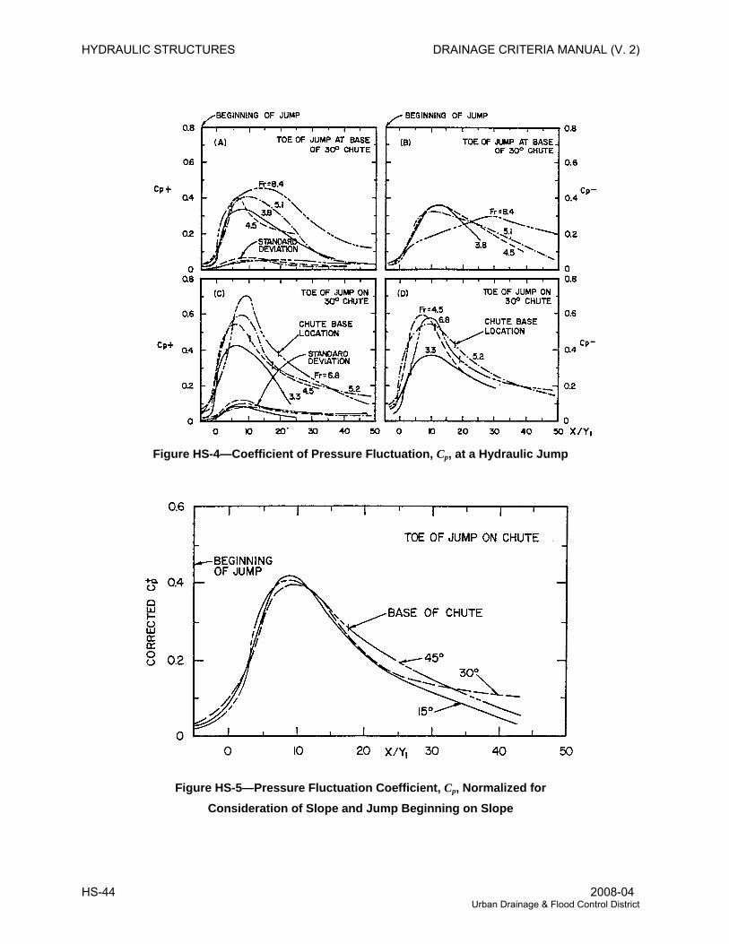
HYDRAULIC STRUCTURES DRAINAGE CRITERIA MANUAL (V. 2)
Figure HS-4—Coefficient of Pressure Fluctuation, Cp, at a Hydraulic Jump
Figure HS-5—Pressure Fluctuation Coefficient, Cp, Normalized for Consideration of Slope and Jump Beginning on Slope
HS-44 2008-04 Urban Drainage & Flood Control District
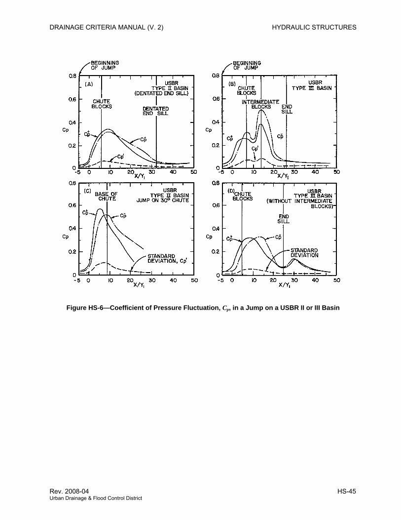
DRAINAGE CRITERIA MANUAL (V. 2) HYDRAULIC STRUCTURES
Figure HS-6—Coefficient of Pressure Fluctuation, Cp, in a Jump on a USBR II or III Basin
Rev. 2008-04 HS-45 Urban Drainage & Flood Control District
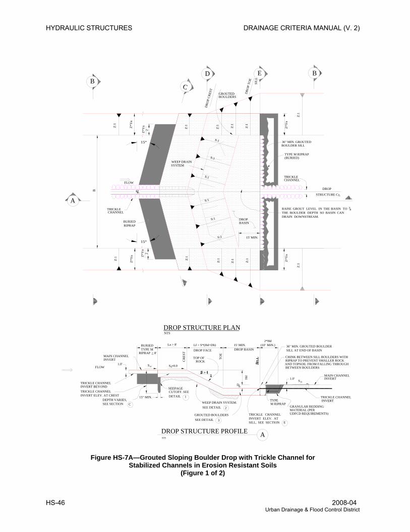
HYDRAULIC STRUCTURES DRAINAGE CRITERIA MANUAL (V. 2)
NTS
DROP FACE DROP BASIN
CR
EST
TOE
15" MIN.
GROUTED BOULDERS
TYPEWEEP DRAIN SYSTEM.
36" MIN. GROUTED
DROP
L
DROPBASIN
WEEP DRAINSYSTEM
NTS
CHINK BETWEEN SILL BOULDERS WITHRIPRAP TO PREVENT SMALLER ROCK
AND TOPSOIL FROM FALLING THROUGH
SEE DETAIL
DROP STRUCTURE PROFILE A
DROP STRUCTURE PLAN
A
BD E
BOULDER SILL
FLOW
FLOW
TRICKLE
Z*Y
n
Z:1
B
TRICKLECHANNEL
TYPE M RIPRAP
La > 8' Lf = S*(Hd+Db) 15' MIN.
S S =0.0
DETAIL
SEEPAGE
1.0'
TRICKLE CHANNELINVERT BEYOND
MAIN CHANNELINVERT
1
2
Hd
D
TRICKLE CHANNELINVERT
1.0'S
36'' MIN. GROUTED BOULDERSILL AT END OF BASIN
MAIN CHANNEL
SEE DETAIL 3
TRICKLE CHANNELINVERT ELEV. AT CREST
M RIPRAPGRANULAR BEDDINGMATERIAL (PERUDFCD REQUIREMENTS)
SILL
STRUCTURE C
BETWEEN BOULDERS
INVERT
TOP OFROCK
CUTOFF. SEE
B
C
DR
OP
TOE
DR
OP
CRES
T
S:1
S:1
GROUTEDBOULDERS
Z*Y
n
Z*Y
n
CHANNEL
(BURIED)
BURIED TYPE M
RIPRAP > 8'
BURIEDRIPRAP
RAISE GROUT LEVEL IN THE BASIN TO 34
THE BOULDER DEPTH SO BASIN CAN DRAIN DOWNSTREAM.
SEE SECTIONDEPTH VARIES,
o
o
Z*Y
n
2*Hd(10' MIN.)
b
S:1
S:1Z*
Yn
2Z*
Yn
2
15' MIN.
15°
15°
o
TRICKLE CHANNEL INVERT ELEV. AT SILL, SEE SECTION E
C
Z:1
Z:1
Z:1
Z:1
Z:1
Z:1
Z:1
Z:1 Z:1
Z:1
Z:1
S:1
S:1
Figure HS-7A—Grouted Sloping Boulder Drop with Trickle Channel for
Stabilized Channels in Erosion Resistant Soils (Figure 1 of 2)
HS-46 2008-04 Urban Drainage & Flood Control District
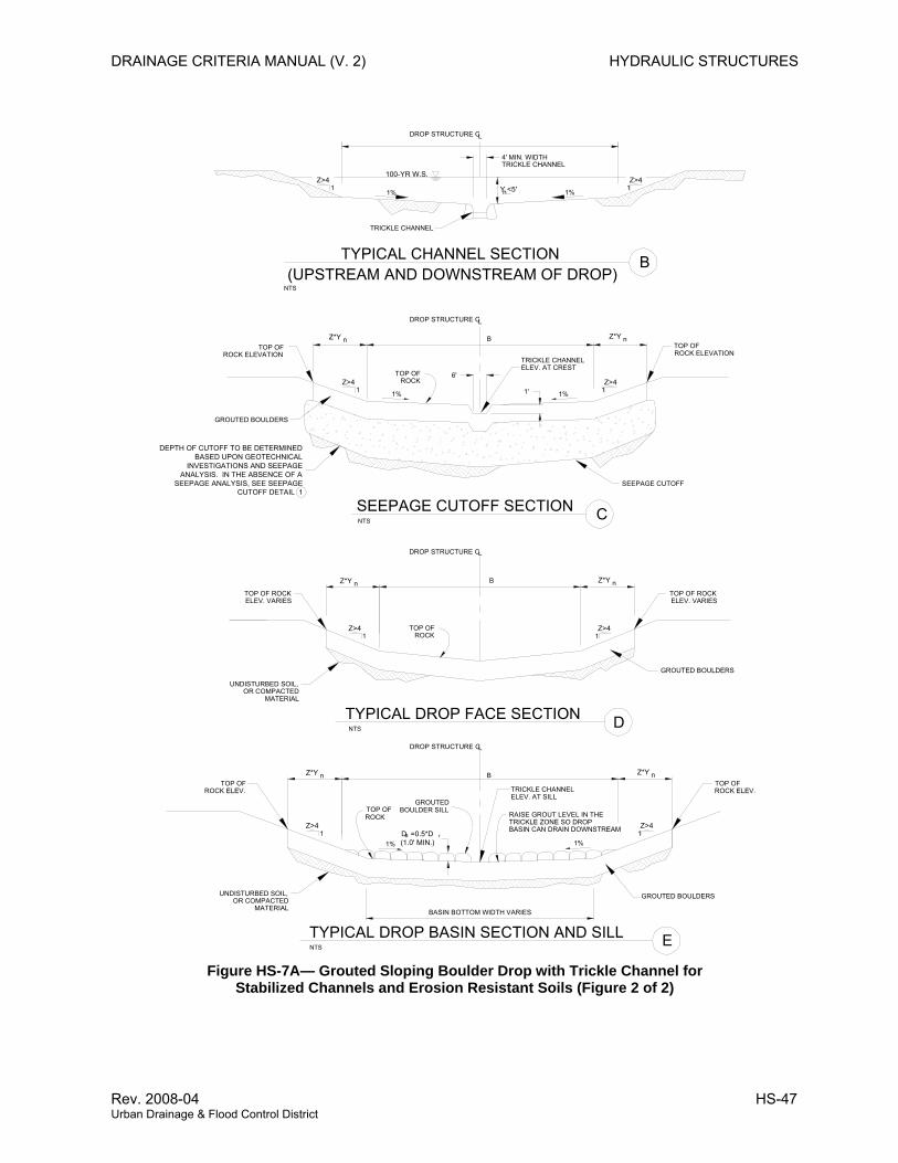
DRAINAGE CRITERIA MANUAL (V. 2) HYDRAULIC STRUCTURES
Figure HS-7A— Grouted Sloping Boulder Drop with Trickle Channel for Stabilized Channels and Erosion Resistant Soils (Figure 2 of 2)
NTS
GROUTED BOULDERS
NTS
GROUTED BOULDERS
NTS
BOULDER SILL
GROUTED BOULDERS
C SEEPAGE CUTOFF SECTION
DTYPICAL DROP FACE SECTION
ETYPICAL DROP BASIN SECTION AND SILL
DROP STRUCTURE CL
DROP STRUCTURE CL
BASIN BOTTOM WIDTH VARIES
DROP STRUCTURE CL
1 1
6'
1'
SEEPAGE CUTOFF
TOP OFROCK ELEVATION ROCK ELEVATION
TOP OF
TRICKLE CHANNELELEV. AT CREST
B
1 1
TOP OF ROCKELEV. VARIES ELEV. VARIES
TOP OF ROCK
B
1 1
TOP OFROCK ELEV. ROCK ELEV.
TOP OFTRICKLE CHANNELELEV. AT SILL
UNDISTURBED SOIL,OR COMPACTED
MATERIAL
MATERIALOR COMPACTED
UNDISTURBED SOIL,
TOP OFROCK
ROCKTOP OF
TOP OFGROUTED
ROCK RAISE GROUT LEVEL IN THETRICKLE ZONE SO DROPBASIN CAN DRAIN DOWNSTREAM
TYPICAL CHANNEL SECTION
NTS
B(UPSTREAM AND DOWNSTREAM OF DROP)
DROP STRUCTURE CL
B
4' MIN. WIDTH
1%11
TRICKLE CHANNEL
Z>4Z>4
Z>4 Z>4
Z>4Z>4
Z>4 Z>4
1%
1%1%
1%1%
Z*Y nZ*Y n
Z*Y nZ*Y n
Z*Y nZ*Y n
Y <5'n
100-YR W.S.
DEPTH OF CUTOFF TO BE DETERMINED BASED UPON GEOTECHNICAL
INVESTIGATIONS AND SEEPAGE ANALYSIS. IN THE ABSENCE OF A
SEEPAGE ANALYSIS, SEE SEEPAGE CUTOFF DETAIL 1
D =0.5*D(1.0' MIN.)
B r
TRICKLE CHANNEL
Rev. 2008-04 HS-47 Urban Drainage & Flood Control District
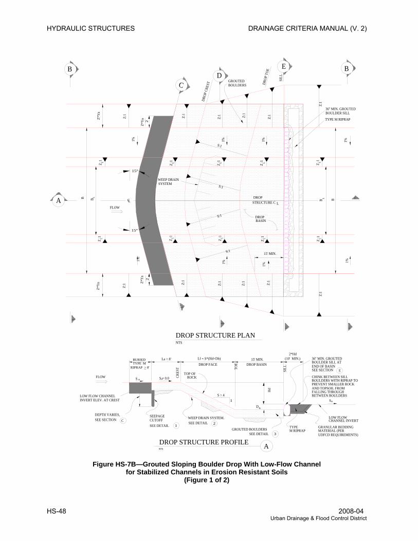
HYDRAULIC STRUCTURES DRAINAGE CRITERIA MANUAL (V. 2)
DROP FACE
WEEP DRAIN SYSTEM.SEE DETAIL
DROP STRUCTURE PROFILE
DROP STRUCTURE PLAN
INVERT ELEV. AT CREST
Z:1
DEPTH VARIES,SEE SECTION
NTS
CUTOFFSEEPAGE
SEE DETAIL 1
FLOW
LOW FLOW CHANNEL
S S = 0.0
NTS
CRES
T
TOP OFROCK
BA B
Z:1
B
WEEP DRAINSYSTEM
FLOW
Z :1
LC
Z :1
Z :1
Z :1
C
GROUTED BOULDERSSEE DETAIL
2
A
D
3
TYPEM RIPRAP
DROP BASIN
1
TOE
Hd
SILL
UDFCD REQUIREMENTS)
CHANNEL INVERTLOW FLOW
GRANULAR BEDDINGMATERIAL (PER
BOULDERS WITH RIPRAP TO
S
36'' MIN. GROUTEDBOULDER SILL ATEND OF BASIN
CHINK BETWEEN SILL
PREVENT SMALLER ROCKAND TOPSOIL FROMFALLING THROUGHBETWEEN BOULDERS
Z:1
STRUCTURE C
S:1
Z :1
S:1
S:1
S:1
Z :1
1%
DROP
Z :1
DROPBASIN
L
Z :1
GROUTED
DROP
CRE
ST
DBOULDERS DR
OP T
OE
SILL
E
B B
Z :1
Z :1
36'' MIN. GROUTEDBOULDER SILL
TYPE M RIPRAP
Z:1
B
1%1% 1%1%
1%1%
1%
L L L L LLLLLL
L L
o
o
Z*Y
nZ*
Yn
2*Hd(10' MIN.)
15' MIN.
Z:1 Z:1
Z:1
Z:1
Z:1
Z:1
15°
15°
Z:1
Z:1
2Z*
Yn
Z*Y
n2
o
b
C
ESEE SECTION
La > 8' Lf = S*(Hd+Db) 15' MIN.
S > 4
BURIED TYPE M
RIPRAP > 8'
Figure HS-7B—Grouted Sloping Boulder Drop With Low-Flow Channel
for Stabilized Channels in Erosion Resistant Soils (Figure 1 of 2)
HS-48 2008-04 Urban Drainage & Flood Control District
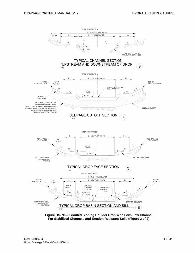
DRAINAGE CRITERIA MANUAL (V. 2) HYDRAULIC STRUCTURES
Figure HS-7B— Grouted Sloping Boulder Drop With Low-Flow Channel For Stabilized Channels and Erosion Resistant Soils (Figure 2 of 2)
SEEPAGE CUTOFF
ELEV. VARIESTOP OF ROCK
ROCK ELEVATIONTOP OF
1 1% 1% 1
TYPICAL DROP BASIN SECTION AND SILL
(UPSTREAM AND DOWNSTREAM OF DROPNTS
NTS
UNDISTURBED SOIL,OR COMPACTED
UNDISTURBED SOIL,
ROCK ELEV.TOP OF
MATERIALOR COMPACTED
1Z*
MATERIAL
BOULDERS
TOP OF ROCKELEV. VARIES
1Z*
ROCK ELEVATION
GROUTED
TOP OF
Z*1
BOULDER
TYPICAL DROP FACE SECTION
B = MAIN CHANNEL WIDTH
GROUTED
SILL
DROP STRUCTURE C
LOW FLOW
ELEV. AT SILL
TOP OFROCK
1%
1
NTS
CHANNEL
L
E
GROUTED BOULDERS
1
1%
D
1Z*
GROUTED BOULDERS
SEEPAGE CUTOFF SECTION
TYPICAL CHANNEL SECTION
Y
DROP STRUCTURE C
1%
1
NTS
ROCKTOP OF
L
DROP STRUCTURE C
1%
1
TOP OFROCK
L
3' MIN.
1
1%
C
Z*
12" THICKNESS TYPE VLRIPRAP, TYP. BOTH SIDES
LOW FLOW CHANNELELEV. AT CREST
1%
Z1
Z*
B
Z*
B = MAIN CHANNEL WIDTH
DROP STRUCTURE C
9' B = LOW FLOW WIDTH
L
Z*
ROCK ELEV.TOP OF
LLZ
LZ LZ
LZLZ
B = LOW FLOW WIDTH
B = LOW FLOW WIDTH
B = LOW FLOW WIDTHL
L
L
L B R
RB
RB
RB
LB
LB
B L
B L
L
L
Y = 3'-5'L
D =0.75*D(1.0' MIN.)
B r
DEPTH OF CUTOFF TO BE DETERMINED BASED UPON
GEOTECHNICAL INVESTIGATIONS AND SEEPAGE ANALYSIS. IN THE ABSENCE
OF A SEEPAGE ANALYSIS, SEE SEEPAGE CUTOFF DETAIL 1
1
1
* *
**
**
* Z > 4* Z > 2.5L
* Z > 4* Z > 2.5L
* Z > 4* Z > 2.5L
* Z > 4* Z > 2.5L
Y = 3'-5'
Y = 3'-5'
Rev. 2008-04 HS-49 Urban Drainage & Flood Control District
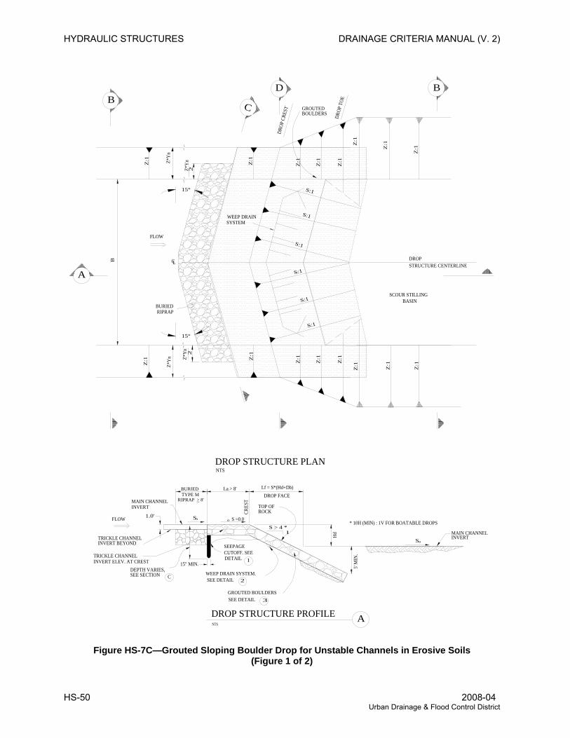
HYDRAULIC STRUCTURES DRAINAGE CRITERIA MANUAL (V. 2)
NTS
DROP FACE
CRES
T
S > 4 *
15" MIN.
GROUTED BOULDERS
WEEP DRAIN SYSTEM.
DROPLC
WEEP DRAINSYSTEM
NTS
SEE DETAIL
DROP STRUCTURE PROFILE A
DROP STRUCTURE PLAN
A
BD
FLOW
FLOW
Z:1Z
:1
B
La > 8' Lf = S*(Hd+Db)
S S =0.0
DETAIL
SEEPAGE
1.0'
TRICKLE CHANNELINVERT BEYOND
MAIN CHANNELINVERT
2
Hd
SMAIN CHANNEL
SEE DETAIL 3
TRICKLE CHANNELINVERT ELEV. AT CREST
Z:1
Z:1
STRUCTURE CENTERLINE
INVERT
TOP OFROCK
CUTOFF. SEE
B
C
DROP
TOE
DROP
CRE
ST
S:1
S:1
S:1
S:1
GROUTEDBOULDERS
Z:1
Z:1
Z*Y
n
BURIED TYPE M
RIPRAP > 8'
BURIEDRIPRAP
Z:1
SEE SECTIONDEPTH VARIES,
o
o
Z*Y
n
S:1
S:1
Z:1
Z:1
Z:1
Z:1
Z:1
Z*Y
n2
Z*Y
n2
15°
15°
o
C
SCOUR STILLINGBASIN
* 10H (MIN) : 1V FOR BOATABLE DROPS
5' M
IN.
Z:1
Z:1
Z:1
Z:1
1
Figure HS-7C—Grouted Sloping Boulder Drop for Unstable Channels in Erosive Soils (Figure 1 of 2)
HS-50 2008-04 Urban Drainage & Flood Control District
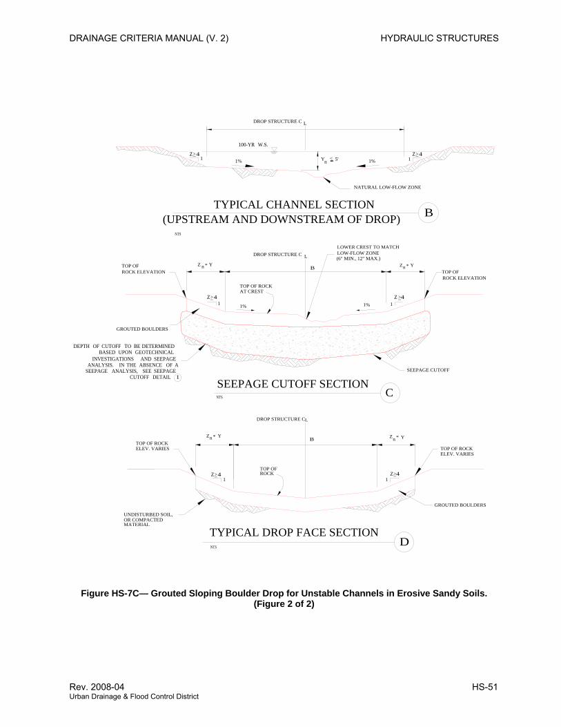
DRAINAGE CRITERIA MANUAL (V. 2) HYDRAULIC STRUCTURES
NTS
GROUTED BOULDERS
NTS
GROUTED BOULDERS
C SEEPAGE CUTOFF SECTION
DTYPICAL DROP FACE SECTION
DROP STRUCTURE CL
SEEPAGE CUTOFF
TOP OFROCK ELEVATION
ROCK ELEVATIONTOP OF
LOWER CREST TO MATCHLOW-FLOW ZONE
BTOP OF ROCKELEV. VARIES
ELEV. VARIESTOP OF ROCK
UNDISTURBED SOIL,OR COMPACTEDMATERIAL
TOP OF ROCKAT CREST
ROCKTOP OF
TYPICAL CHANNEL SECTION
NTS
B(UPSTREAM AND DOWNSTREAM OF DROP)
DROP STRUCTURE C L
B
1%
NATURAL LOW-FLOW ZONE
Z>4 Z>4
Z >4Z>4
Z>4 Z>41%
1%1%
100-YR W.S.
DEPTH OF CUTOFF TO BE DETERMINED BASED UPON GEOTECHNICAL
INVESTIGATIONS AND SEEPAGE ANALYSIS. IN THE ABSENCE OF A
SEEPAGE ANALYSIS, SEE SEEPAGE CUTOFF DETAIL 1
(6" MIN., 12" MAX.)DROP STRUCTURE C L
Yn 5'<
Zn Y*Z n Y*
1 1
11
Zn Y*Zn Y*
11
Figure HS-7C— Grouted Sloping Boulder Drop for Unstable Channels in Erosive Sandy Soils. (Figure 2 of 2)
Rev. 2008-04 HS-51 Urban Drainage & Flood Control District
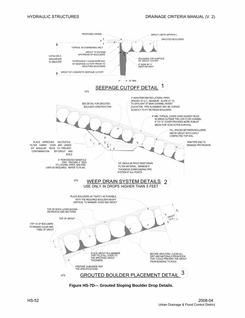
HYDRAULIC STRUCTURES DRAINAGE CRITERIA MANUAL (V. 2)
FROM BONDING TO ROCK.THAT COULD PREVENT THE GROUTDIRT AND MATERIALS FROM ROCKBEFORE GROUTING, CLEAN ALL
THICKNESSTHE SPECIFIED GROUTTHAT FILLS ALL VOIDS TOPLACE GROUT IN A MANNER
THE SPECIFICATIONS
GROUT
GROUTED BOULDER PLACEMENT DETAIL
PREPARE SUBGRADE PER
11
NTS
NTS
TOP OF GROUT
D
MINIMIZE PROTRUSIONTRIM PIPE END TO
SLIGHTLY TO FIT BETWEEN BOULDERS.ELEVATION. PIPE ALIGNMENT MAY BE CURVEDTO DAYLIGHT AT MAIN CHANNEL INVERTSPACED 10' O.C., MAXIMUM. SLOPE AT 1%4" NON-PERFORATED LATERAL PIPES
SYSTEM AT ALL POINTSTHICKNESS SURROUNDING PIPEFILTER MATERIAL. MINIMUM 6" 3/4" ANGULAR ROCK WEEP DRAIN
CAPS AS REQUIRED. REFER TO PLAN.TO LATERAL PIPES, AND END
PIPE. PROVIDE 4'' TEES4'' PERFORATED MANIFOLD
BOULDER CONSTRUCTIONSEE DETAIL FOR GROUTED
6"
6"
1NTS
2
3
TOP OF ROCK LAYER SHOWNON PROFILE AND SECTIONS
PLACE BOULDERS AS TIGHTLY AS POSSIBLE WITH THE REQUIRED BOULDER HEIGHT VERTICAL TO MINIMIZE VOIDS AND GROUT
1/2 D
FILL SPACES BETWEEN BOULDERSABOVE GROUT WITH LIGHLY COMPACTED TOP SOIL.
4" MIN. TOPSOIL COVER OVER HIGHEST ROCK IN AREAS OUTSIDE THE LOW FLOW CHANNEL. 6" TO 12" COVER PROVIDES MORE RUBUST MEDIA FOR VEGETATION SURVIVAL.
r
r
FEET5 THAN HIGHER DROPS IN ONLY USE
PLACE APPROVED GEOTEXTILE FILTER FABRIC OVER AND UNDER 3/4" ANGULAR ROCK TO PREVENT CONTAMINATION BY GROUT AND
SOILS
GROUTED BOULDERS
0.8*Hd OR 4',WHICHEVERIS GREATER
GROUT OF CONCRETE SEEPAGE CUTOFF
THOROUGHLY CLEAN SURFACEOF SEEPAGE CUTOFF PRIOR TO GROUTING BOULDERS
15" MIN.
GROUT TO EXTENDUPSTREAM OF BOULDERS
PROPOSED GRADE
TOPSOIL IN OVERBANKS ONLY
ROUGHEN TOP SURFACEOF GROUT CUTOFF
GROUT LIMITS (APPROX.)
DEEP KEYWAY6" WIDE BY 4"
TOP 1/2 OF BOULDERSTO REMAIN CLEAN AND FREE OF GROUT
WEEP DRAIN SYSTEM DETAILS
SEEPAGE CUTOFF DETAIL
4"
Figure HS-7D— Grouted Sloping Boulder Drop Details.
HS-52 2008-04 Urban Drainage & Flood Control District
DRAINAGE CRITERIA MANUAL (V. 2) HYDRAULIC STRUCTURES
GROUT NOTES
Material Specifications
All grout shall have a minimum 28-day compressive strength equal to 3200 psi.
One cubic yard of grout shall have a minimum of six (6) sacks of Type II Portland cement.
A maximum of 25% Type F Fly Ash may be substituted for the Portland cement.
For Type A grout, the aggregate shall be comprised of 70% natural sand (fines) and 30% 3 8 -inch rock (coarse).
For Type B grout, the aggregate shall be comprised of 3 4 -inch maximum gravel, structural concrete aggregate.
Type B grout shall be used in streams with significant perennial flows.
The grout slump shall be 4-inches to 6-inches.
Air entrainment shall be 5.5%-7.5%.
To control shrinkage and cracking, 1.5 pounds of Fibermesh, or equivalent, shall be used per cubic yard of grout.
Color additive in required amounts shall be used when so specified by contract.
1.
2.
3.
4.
5.
6.
7.
8.
9.
10.
Placement Specifications
All Type A grout shall be delivered by means of a low pressure (less than 10 psi) grout pump using a 2-inch diameter nozzle.
All Type B grout shall be delivered by means of a low pressure (less than 10 psi) concrete pump using a 3-inch diameter nozzle
Full depth penetration of the grout into the boulder voids shall be achieved by injecting grout starting with the nozzle near the bottom and raising it as grout fills, while vibrating grout into place using a pencil vibrator.
After grout placement, exposed boulder faces shall be cleaned with a wet broom.
All grout between boulders shall be treated with a broom finish.
All finished grout surfaces shall be sprayed with a clear liquid membrane curing compound as specified in ASTM C-309.
Special procedures shall be required for grout placement when the air temperatures are less than 40°F or greater than 90°F.
design engineer of the procedures to be used for protecting the grout.
Clean Boulders by brushing and washing before grouting.
1.
2.
3.
4.
5.
6.
7.
8.
Figure HS-8—Specifications and Placement Instructions for Grout in Sloping Boulder Drops.
Rev. 2008-04 HS-53 Urban Drainage & Flood Control District
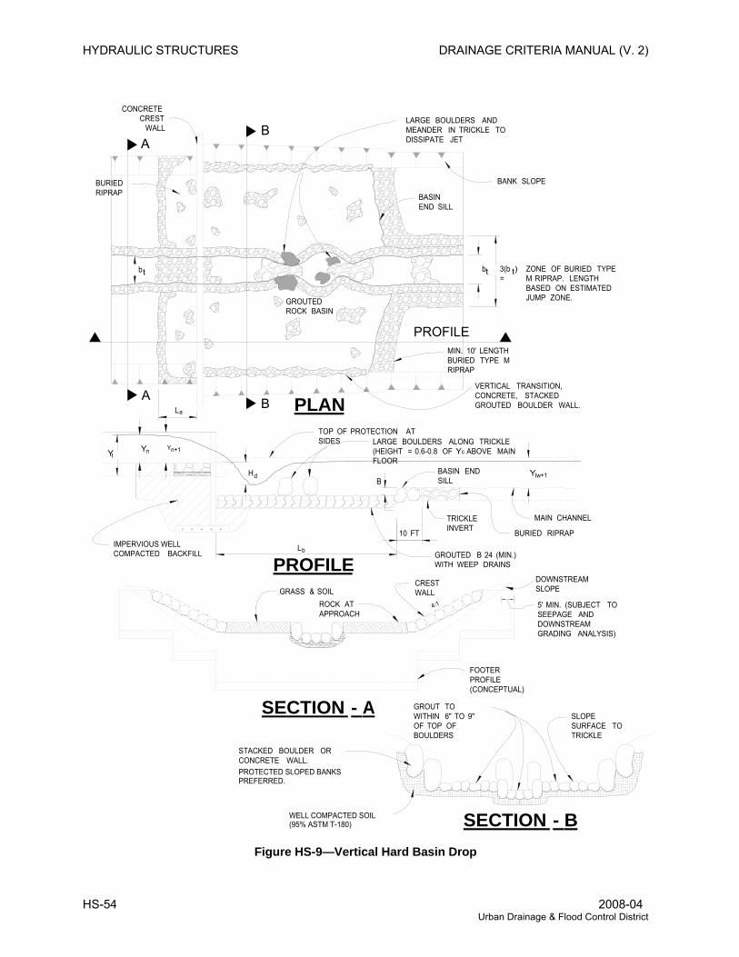
HYDRAULIC STRUCTURES DRAINAGE CRITERIA MANUAL (V. 2)
CONCRETECREST
WALLLARGE BOULDERS AND MEANDER IN TRICKLE TO DISSIPATE JET
BASIN END SILL
BANK SLOPEBURIED RIPRAP
b b 3(b ) =
ZONE OF BURIED TYPE M RIPRAP. LENGTH BASED ON ESTIMATED JUMP ZONE.GROUTED
ROCK BASIN
LA
A
B
B
PROFILEMIN. 10' LENGTH BURIED TYPE M RIPRAP
VERTICAL TRANSITION, CONCRETE, STACKED GROUTED BOULDER WALL.PLAN
Y Y Y
BACKFILLCOMPACTED IMPERVIOUS WELL
H
TOP OF PROTECTION AT SIDES LARGE BOULDERS ALONG TRICKLE
(HEIGHT = 0.6-0.8 OF Yc ABOVE MAIN FLOOR
BASIN END SILL
TRICKLE INVERT
GROUTED B 24 (MIN.) WITH WEEP DRAINS
BURIED RIPRAP
MAIN CHANNEL
L
B
10 FT
Y
PROFILEGRASS & SOIL
ROCK AT APPROACH
CREST WALL
4:1
DOWNSTREAM SLOPE
FOOTER PROFILE (CONCEPTUAL)
SECTION - A
5' MIN. (SUBJECT TO SEEPAGE AND DOWNSTREAM GRADING ANALYSIS)
SECTION - B
GROUT TO WITHIN 6" TO 9" OF TOP OF BOULDERS
PROTECTED SLOPED BANKS PREFERRED.
WALL. CONCRETE OR BOULDER STACKED
SLOPE SURFACE TO TRICKLE
t t t
a
tn n+1
d tw+1
b
WELL COMPACTED SOIL(95% ASTM T-180)
Figure HS-9—Vertical Hard Basin Drop
HS-54 2008-04 Urban Drainage & Flood Control District
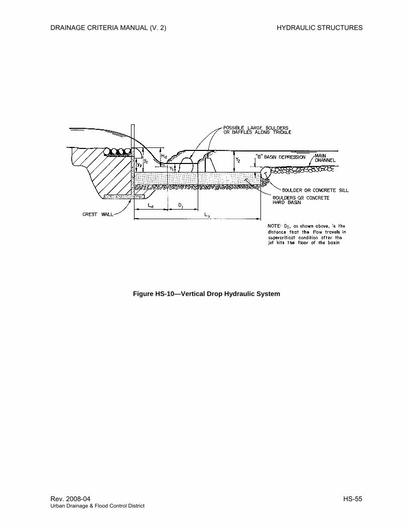
DRAINAGE CRITERIA MANUAL (V. 2) HYDRAULIC STRUCTURES
Figure HS-10—Vertical Drop Hydraulic System
Rev. 2008-04 HS-55 Urban Drainage & Flood Control District
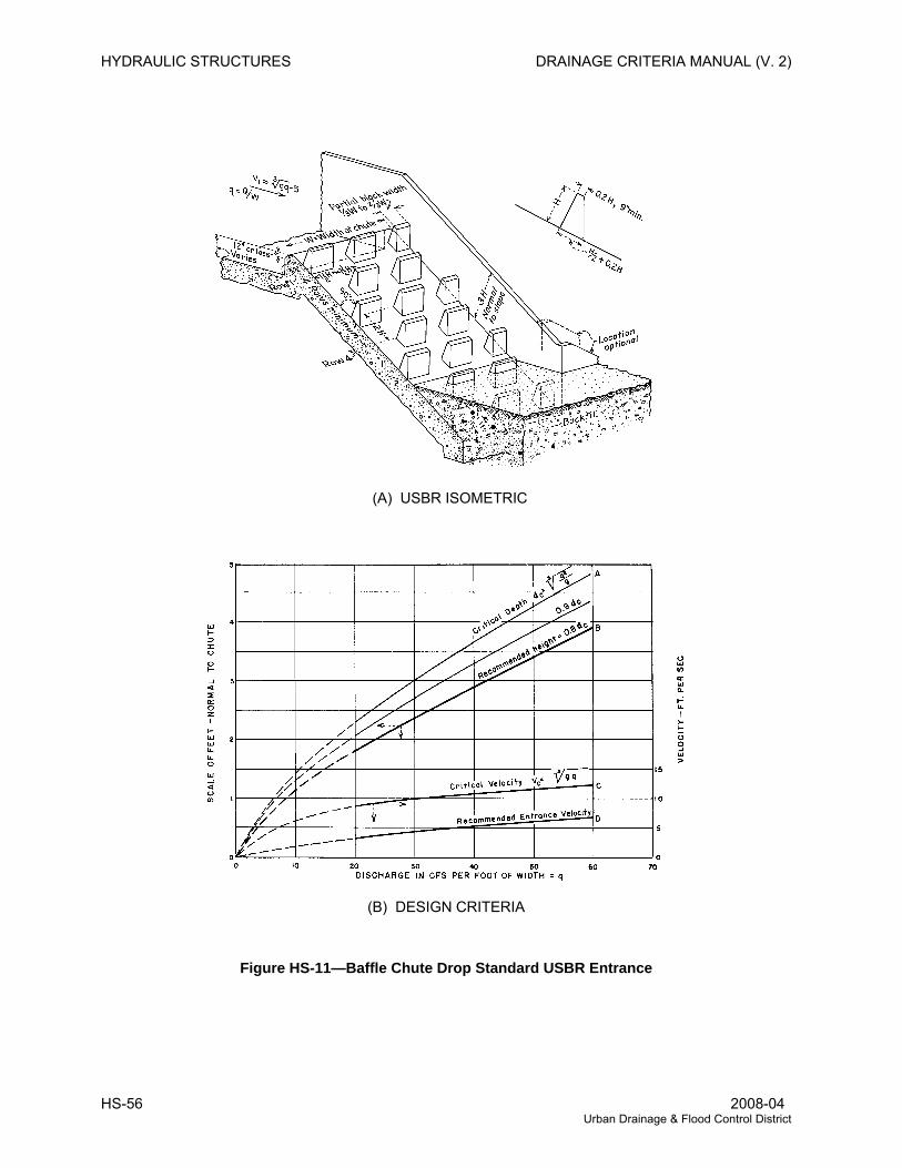
HYDRAULIC STRUCTURES DRAINAGE CRITERIA MANUAL (V. 2)
(A) USBR ISOMETRIC
(B) DESIGN CRITERIA
Figure HS-11—Baffle Chute Drop Standard USBR Entrance
HS-56 2008-04 Urban Drainage & Flood Control District
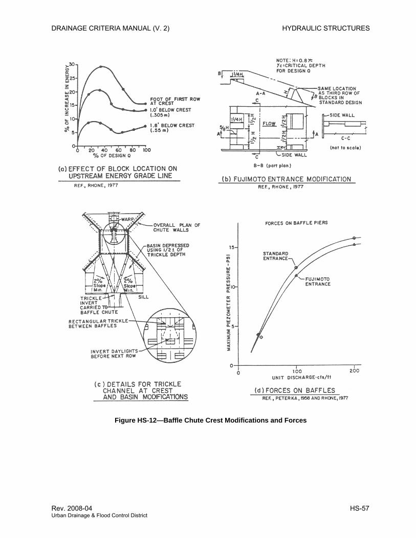
DRAINAGE CRITERIA MANUAL (V. 2) HYDRAULIC STRUCTURES
Figure HS-12—Baffle Chute Crest Modifications and Forces
Rev. 2008-04 HS-57 Urban Drainage & Flood Control District
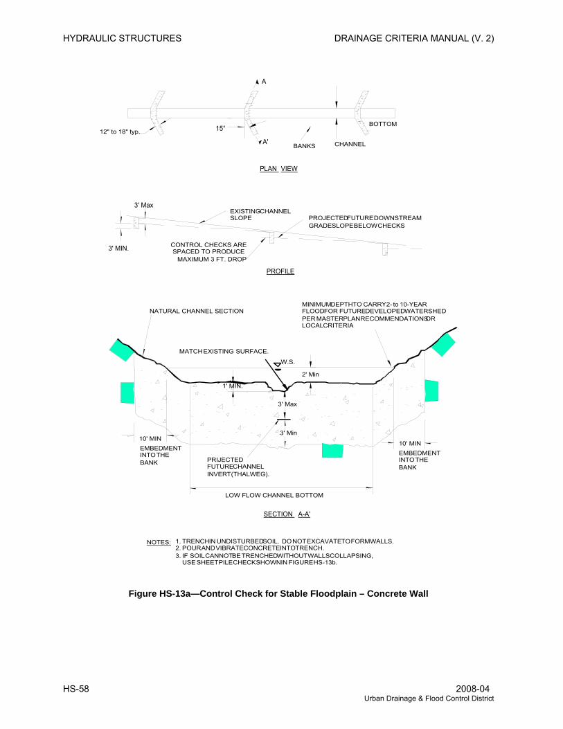
HYDRAULIC STRUCTURES DRAINAGE CRITERIA MANUAL (V. 2)
BOTTOM
CHANNEL
3' MIN.
3' MaxEXISTING CHANNEL SLOPE PROJECTED FUTURE DOWNSTREAM
GRADE SLOPE BELOW CHECKS
A
A'
CONTROL CHECKS ARESPACED TO PRODUCE
MAXIMUM 3 FT. DROP
PLAN VIEW
PROFILE
NATURAL CHANNEL SECTION
SURFACE.EXISTING MATCH
MINIMUM DEPTH TO CARRY 2- to 10-YEARFLOOD FOR FUTURE DEVELOPED WATERSHEDPER MASTER PLAN RECOMMENDATIONS OR LOCAL CRITERIA
2' Min
10' MINEMBEDMENT INTO THEBANK
1' MIN.
SECTION A-A'
3' Max
3' Min
PRIJECTED FUTURE CHANNELINVERT (THALWEG).
W.S.
15°12" to 18" typ.
LOW FLOW CHANNEL BOTTOM
NOTES:
BANKS
10' MIN
1. TRENCH IN UNDISTURBED SOIL. DO NOT EXCAVATE TO FORM WALLS.2. POUR AND VIBRATE CONCRETE INTO TRENCH.3. IF SOIL CANNOT BE TRENCHED WITHOUT WALLS COLLAPSING, USE SHEET PILE CHECK SHOWN IN FIGURE HS-13b.
EMBEDMENT INTO THEBANK
Figure HS-13a—Control Check for Stable Floodplain – Concrete Wall
HS-58 2008-04 Urban Drainage & Flood Control District
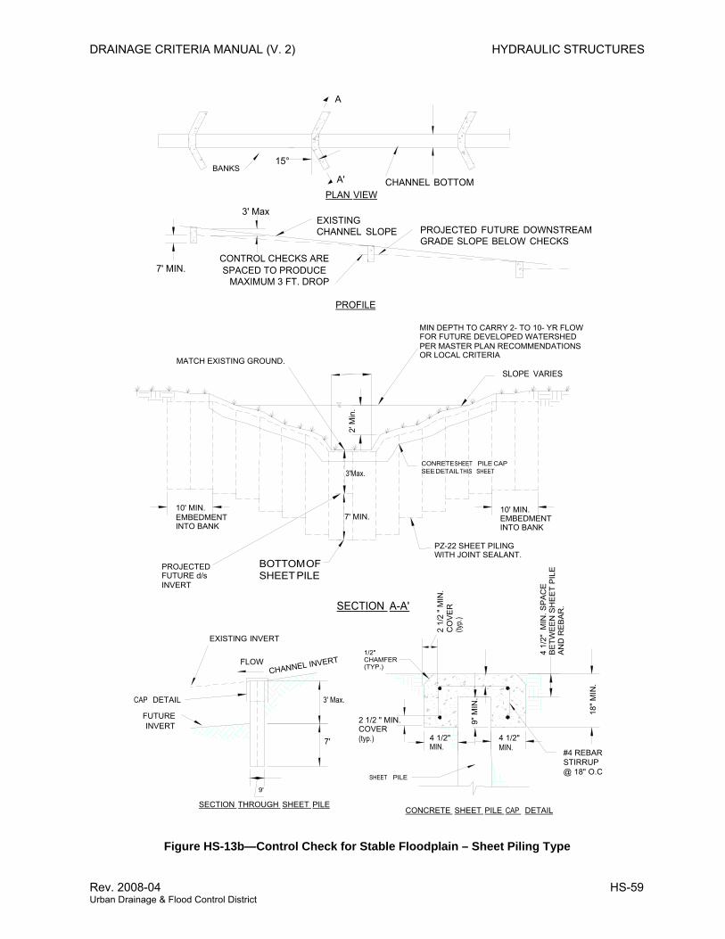
DRAINAGE CRITERIA MANUAL (V. 2) HYDRAULIC STRUCTURES
CHANNEL BOTTOM
7' MIN.
3' MaxEXISTING CHANNEL SLOPE PROJECTED FUTURE DOWNSTREAM
GRADE SLOPE BELOW CHECKS
A
A'
CONTROL CHECKS ARESPACED TO PRODUCE
MAXIMUM 3 FT. DROP
PLAN VIEW
PROFILE
15°
SLOPE VARIES
2' M
in.
BOTTOM OF SHEET PILE
CONRETE SHEET PILE CAPSEE DETAIL THIS SHEET
7' MIN.
3'Max.
SECTION A-A'
FLOWCHANNEL INVERT
EXISTING INVERT
FUTURE INVERT
CAP DETAIL
9'
7'
3' Max.
SECTION THROUGH SHEET PILE
SHEET PILE
4 1/2"MIN.
18" M
IN.
9" M
IN.
CONCRETE SHEET PILE CAP DETAIL
#4 REBAR STIRRUP @ 18" O.C
BANKS
MIN DEPTH TO CARRY 2- TO 10- YR FLOWFOR FUTURE DEVELOPED WATERSHEDPER MASTER PLAN RECOMMENDATIONSOR LOCAL CRITERIA
MATCH EXISTING GROUND.
PZ-22 SHEET PILINGWITH JOINT SEALANT.
10' MIN.EMBEDMENT INTO BANK
10' MIN.EMBEDMENT INTO BANK
4 1/
2" M
IN. S
PA
CE
B
ETW
EE
N S
HE
ET
PIL
E
AN
D R
EB
AR
.
2 1/
2 " M
IN.
CO
VE
R
(typ.
)
2 1/2 " MIN. COVER (typ.)
PROJECTED FUTURE d/sINVERT
4 1/2"MIN.
1/2" CHAMFER(TYP.)
Figure HS-13b—Control Check for Stable Floodplain – Sheet Piling Type
Rev. 2008-04 HS-59 Urban Drainage & Flood Control District
HYDRAULIC STRUCTURES DRAINAGE CRITERIA MANUAL (V. 2)
3.0 CONDUIT OUTLET STRUCTURES
3.1 General
Energy dissipation or stilling basin structures are required to minimize scour damages caused by high exit
velocities and turbulence at conduit outlets. Similarly, culverts nearly always require special
consideration at their outlets. Outlet structures can provide a high degree of energy dissipation and are
generally effective even with relatively low tailwater control. Rock protection at conduit outlets (see the
MAJOR DRAINAGE chapter) is appropriate where moderate outlet conditions exist; however, there are
many situations where rock basins are impractical. Reinforced concrete outlet structures are suitable for
a wide variety of site conditions. In some cases, they are more economical than larger rock basins,
particularly when long-term costs are considered.
Any outlet structure must be designed to match the receiving stream conditions. The following steps
include an analysis of the probable range of tailwater and bed conditions that can be anticipated including
degradation, aggradation, and local scour.
Hydraulic concepts and design criteria are provided in this section for an impact stilling basin and
adaptation of a baffle chute to conduit outlets. Use of concrete is often more economical due to structure
size or local availability of materials. Initial design selection should include consideration of a conduit
outlet structure if any of the following situations exist: (1) high-energy dissipation efficiency is required,
where hydraulic conditions approach or exceed the limits for alternate designs (see the MAJOR
DRAINAGE chapter); (2) low tailwater control is anticipated; or (3) site conditions, such as public use
areas, where plunge pools and standing water are unacceptable because of safety and appearance, or at
locations where space limitations direct the use of a concrete structure.
Longer conduits with large cross-sectional areas are designed for significant discharges and often with
high velocities requiring special hydraulic design at their outlets. Here, dam outlet and spillway terminal
structure technology is appropriate (USBR 1987). Type II, III or IV stilling basins, submerged bucket with
plunge basin energy dissipators and slotted-grating dissipators can be considered when appropriate to
the site conditions. For instance, a plunge basin may have applicability where discharge is to a wet
detention pond or a lake. Alternate designs of pipe exit energy dissipators are provided in this Manual
that can be matched to a variety of pipe sizes and pipe outlet physical and hydraulic settings.
3.2 Impact Stilling Basin
Most design standards for an impact stilling basin are based on the USBR Type VI basin, often called
“impact dissipator” or conduit “outlet stilling basin”. This basin is a relatively small structure that is very
efficient energy in dissipating energy without the need of tailwater. The original hydraulic design
reference by Biechley (1971) is based on model studies. Additional structural design details are provided
by Aisenbrey, et al. (1974) and Peterka (1984).
HS-60 2008-04 Urban Drainage & Flood Control District

DRAINAGE CRITERIA MANUAL (V. 2) HYDRAULIC STRUCTURES
The Type VI basin was originally designed to operate continuously at the design flow rate. However, it is
applicable for use under the varied flow conditions of stormwater runoff. The use of this outlet basin is
limited only by structural and economic considerations.
Energy dissipation is accomplished through the turbulence created by the loss of momentum as flow
entering the basin impacts a large overhanging baffle. At high flow, further dissipation is produced as
water builds up behind the baffle to form a highly turbulent backwater zone. Flow is then redirected under
the baffle to the open basin and out to the receiving channel. A check at the basin end reduces exit
velocities by breaking up the flow across the basin floor and improves the stilling action at low to
moderate flow rates.
The generalized, slightly modified, USBR Type IV Impact Basin design configuration is shown in
Figure HS-14, which consists of an open concrete box attached directly to the conduit outlet. The width,
W, is a function of the Froude number and can be determined using Figure HS-15. The sidewalls are
high enough to contain most of the splashing during high flows and slope down to form a transition to the
receiving channel. The inlet pipe is vertically aligned with an overhanging L-shaped baffle such that the
pipe invert is not lower than the bottom of the baffle. The end check height is equal to the height under
the baffle to produce tailwater in the basin. The alternate end transition (at 45 degrees) is recommended
for grass-lined channels to reduce the downstream scour potential.
The impact basin can also be adapted to multiple pipe installations. Such modifications are discussed
later, but it should be noted that modifications to the design may affect the hydraulic performance of the
structure. Model testing of designs that vary significantly from the standard is recommended.
3.2.1 Modified Impact Basins for Smaller Outlets For smaller pipe outlets a modified version of the USBR Type IV Impact Basin is suggested in this
Manual. Figure HS-16a provides a design layout for circular outlets ranging in size from 18-inches to
48-inches in diameter and Figure HS-16b for pipes 18-inches in diameter and smaller. The latter was
added for primary use as an outlet energy dissipator upstream of forebays of small extended detention
basins, sand filters and other structural best management practices requiring energy dissipation at the
end of the pipe delivering water to the BMP facility.
Unlike the Type IV impact basin, the modified basins do not require sizing for flow under normal
stormwater discharge velocities recommended for storm sewers in this Manual. However, their use is
limited to exit velocities of 18 feet per second or less. For larger conduits and higher exit velocities, it is
recommended that the standard Type IV impact basin be used instead.
3.2.2 Low-flow Modifications The standard design will retain a standing pool of water in the basin bottom that is generally undesirable
from an environmental and maintenance standpoint. As a result, the standard USBR design has been
Rev. 2008-04 HS-61 Urban Drainage & Flood Control District
HYDRAULIC STRUCTURES DRAINAGE CRITERIA MANUAL (V. 2)
modified herein for urban applications to allow drainage of the basin bottom during dry periods. This
situation should be alleviated where practical by matching the receiving channel low-flow invert to the
basin invert. A low-flow gap is extended through the basin end check wall. The gap in the check should
be as narrow as possible to minimize effects on the check hydraulics. This implies that a narrow and
deeper (1½- to 2-foot) low-flow channel will work better than a shallow and wide gap section.
For the modified impact basin illustrated in Figure HS-16a, the downstream geometry recognizes the
need for a trickle channel and also provides for a modification when this structure is used upstream of a
forebay in an Extended Detention Basin or other BMP requiring energy dissipation at the entrance.
Low-flow modifications have not been fully tested to date. Caution is advised to avoid compromising the
overall hydraulic performance of the structure. Other ideas are possible including locating the low-flow
gap at one side (off center) to prevent a high velocity jet from flowing from the pipe straight down the low-
flow channel. The optimal configuration results in continuous drainage of the basin area and helps to
reduce the amount of siltation.
3.2.3 Multiple Conduit Installations Where two or more conduits of different sizes outlet in proximity, a composite structure can be
constructed to eliminate common walls. This can be somewhat awkward since each basin “cell” must be
designed as an individual basin with different height, width, etc. Where possible, a more economical
approach is to combine storm sewers underground, at a manhole or vault, and bring a single, combined
pipe to the outlet structure.
When using a Type IV impact basin shown in Figure HS-14 for two side-by-side pipes of the same size,
the two pipes may discharge into a single basin. If the basin’s design width for each pipe is W, the
combined basin width for two pipes would be 1.5W. When the flow is different for the two conduits, the
design width W is based on the pipe carrying the higher flow. For the modified impact basin shown in
Figure HS-16, add 1/2 D space between the pipes and to each outside pipe edge when two pipes
discharge into the basin to determine the width of the headwall and extent the width of the impact wall to
match the outside edges of the two pipes. The effect of mixing and turbulence of the combined flows in
the basin has not been model tested to date.
Remaining structure dimensions are based on the design width of a separate basin W. If the two pipes
have different flow, the combined structure is based on the higher Froude number when designing the
Type IV basins. Use of a handrail is suggested around the open basin areas where safety is a concern.
Access control screens or grating where necessary are a separate design consideration. A hinged rack
has been used on a few projects in the District.
3.2.4 General Design Procedure for Type IV Impact Basin 1. Determine the design hydraulic cross-sectional area just inside the pipe, at the outlet. Determine
HS-62 2008-04 Urban Drainage & Flood Control District
DRAINAGE CRITERIA MANUAL (V. 2) HYDRAULIC STRUCTURES
the effective flow velocity, V, at the same location in the pipe. Assume depth ( ) 2/1sec tA and
compute the Froude number = ( )
D =
2/1gDV
2. The entrance pipe should be turned horizontally at least one pipe diameter equivalent length
upstream from the outlet. For pipe slopes greater than 15 degrees, the horizontal length should
be a minimum of two pipe diameters.
3. Determine the basin width, W, by entering the Froude number and effective flow depth into Figure
HS-15. The remaining dimensions are proportional to the basin width according to Figure HS-14.
The basin width should not be oversized since the basin is inherently oversized for less than
design flows. Larger basins become less effective as the inflow can pass under the baffle.
4. Structure wall thickness, steel reinforcement, and anchor walls (underneath the floor) should be
designed using accepted structural engineering methods. Note that the baffle thickness, tb, is a
suggested minimum. It is not a hydraulic parameter and is not a substitute for structural analysis.
Hydraulic forces on the overhanging baffle may be approximated by determination of the
hydraulic jet force at the outlet:
Fj = 1.94 Vout Qdes (force in pounds) (HS-15)
Qdes = maximum design discharge (cfs)
Vout = velocity of the outlet jet (ft/sec)
5. Type “M” rock riprap should be provided in the receiving channel from the end check to a
minimum distance equal to the basin width. The depth of rock should be equal to the check
height or at least 2.0 feet. Rock may be buried to finished grades and planted as desired.
6. The alternate end check and wingwall shown in Figure HS-14 are recommended for all grass-
lined channel applications to reduce the scour potential below the check wall.
7. Ideally, the low-flow invert matches the floor invert at the basin end and the main channel
elevation is equal to the top of the check. For large basins where the check height, d, becomes
greater than the low-flow depth, dimension d in Figure HS-14 may be reduced by no more than
one-third. It should not be reduced to less than 2 feet. This implies that a deeper low-flow
channel (1.5 to 2.0 feet) will be advantageous for these installations. The alternate when d
exceeds the trickle flow depth is that the basin area will not drain completely.
8. A check section should be constructed directly in front of the low-flow notch to break up bottom
flow velocities. The length of this check section should overlap the width of the low flow and its
dimension is shown in Figure HS-14.
Rev. 2008-04 HS-63 Urban Drainage & Flood Control District
HYDRAULIC STRUCTURES DRAINAGE CRITERIA MANUAL (V. 2)
3.3 Pipe Outlet Rundowns
3.3.1 Baffle Chute Rundown The baffle chute developed by the USBR (1958) has also been adapted to use at pipe outlets. This
structure is well suited to situations with large conduit outfalls and at outfalls to channels in which some
future degradation is anticipated. As mentioned previously, the apron can be extended at a later time to
account for channel degradation. This type of structure is only cost effective if a grade drop is necessary
below the outfall elevation.
Figure HS-17 illustrates a general configuration for a baffled outlet application for a double box culvert
outlet. In this case, an expansion zone occurs just upstream of the approach depression. The
depression depth is designed as required to reduce the flow velocity at the chute entrance. The
remaining hydraulic design is the same as for a standard baffle chute using conditions at the crest to
establish the design. The same crest modifications are applicable to allow drainage of the approach
depression, to reduce the upstream backwater effects of the baffles, and to reduce the problems of debris
accumulation and standing water at the upstream row of baffles.
Flow entering the chute should be well distributed laterally across the width of the chute. The velocity
should be below critical velocity at the crest of the chute. To insure low velocities at the upstream end, it
may be necessary to provide a short energy dissipating pool. The sequent or conjugate depth in the
approach basin should be sized to prevent jump sweep-out, but the basin length may be considerably
less than a conventional hydraulic jump basin since its primary purpose is only to reduce the average
entrance velocity. A basin length of twice the sequent depth will usually provide ample basin length. The
end check of the pool may be used as the crest of the chute as shown in Figure HS-17.
3.3.2 Grouted Boulder Chute Rundown Another option for rundowns at outlets of larger pipes is to use a grouted boulder rundown illustrated in
Figure 18. This type of rundown has been used successfully for several large storm sewers entering the
South Platte River. It is critical that the details shown in Figure 18 be strictly followed and the grout and
the actual filling of spaces between the boulders with grout closely adhere to the recommendations for
grouted boulders provided in the Major Drainage Chapter of this Manual.
If the exit velocities of the pipe exceeds 12 feet per second, an approach chute for the baffle chute
rundown described above should be considered and provided. If this approach chute is lined with
grouted boulders in a manner called for in the Major Drainage Chapter, the stilling basin sill can be
eliminated.
3.4 Low Tailwater Riprap Basins at Pipe Outlets
3.4.1 General The design of low tailwater riprap basins for storm sewer pipe outlets and at some culvert outlets is
HS-64 2008-04 Urban Drainage & Flood Control District
DRAINAGE CRITERIA MANUAL (V. 2) HYDRAULIC STRUCTURES
necessary when the receiving or downstream channel may have little or no flow or tailwater at time when
the pipe or culvert is in operation. Design criteria are provided in Figures HS-19a through HS-20c.
3.4.2 Objective By providing a low tailwater basin at the end of a storm sewer conduit or culvert, the kinetic energy of the
discharge is dissipated under controlled conditions without causing scour at the channel bottom.
Photograph HS-12 shows a fairly large low tailwater basin.
3.4.3 Low Tailwater Basin Design Low tailwater is defined as being equal to or less than ⅓ of the height of the storm sewer, that is:
3Dyt ≤ or
3Hyt ≤
in which:
yt = tailwater depth at design
D = diameter of circular pipe (ft)
H = height of rectangular pipe (ft)
3.4.3.1 Finding Flow Depth and Velocity of Storm Sewer Outlet Pipe The first step in the design of a scour protection basin at the outlet of a storm sewer is to find the depth
and velocity of flow at the outlet. Pipe-full flow can be found using Manning’s equation.
( ) 213249.1ofullfullfull SRA
nQ = (HS-16a)
Then and the pipe-full velocity can be found using the continuity equation.
fullfullfull AQV = (HS-16a)
The normal depth of flow, d, and the velocity in a conduit can be found with the aid of Figure HS-20a and
Figure HS-20b. Using the known design discharge, Q, and the calculated pipe-full discharge, Qfull, enter
Figure HS-20a with the value of Q/Qfull and find d/D for a circular pipe of d/H for a rectangular pipe.
Compare the value of d/D (or d/H) with the one obtained from Figure HS-20b using the Froude parameter.
5.2DQ or ( )51wHQ (HS-16a)
Choose the smaller of the two (d/D or d/H) ratios to calculate the flow depth at the end of the pipe.
( DdDd = ) or ( HdHd = ) (HS-16b)
Rev. 2008-04 HS-65 Urban Drainage & Flood Control District
HYDRAULIC STRUCTURES DRAINAGE CRITERIA MANUAL (V. 2)
Again, enter Figure HS-19a using the smaller d/D (or d/H) ratio to find the A/Afull ratio. Then,
( ) fullfull AAAA = (HS-16c)
Finally,
AQV = (HS-16d)
In which for Equations 16a through 16d above:
Afull = cross-sectional area of the pipe (ft2)
A = area of the design flow in the end of the pipe (ft2)
n = Manning’s n for the pipe full depth
Qfull = pipe full discharge at its slope (cfs)
R = hydraulic radius of the pipe flowing full, ft [Rfull = D/4 for circular pipes, Rfull = Afull/(2H + 2w) for
rectangular pipes, where D = diameter of a circular conduit, H = height of a rectangular
conduit, and w = width of a rectangular conduit (ft)]
So = longitudinal slope of the pipe (ft/ft)
V = design flow velocity at the pipe outlet (ft/sec)
Vfull = flow velocity of the pipe flowing full (ft/sec)
3.4.3.2 Riprap Size For the design velocity, use Figure HS-20c to find the size and type of the riprap to use in the scour
protection basin downstream of the pipe outlet (i.e., B18, H, M or L). First, calculate the riprap sizing
design parameter, Pd , namely,
( 2/12 gdVPd += ) (HS-16e)
in which:
V = design flow velocity at pipe outlet (ft/sec)
g = acceleration due to gravity = 32.2 ft/sec2
d = design depth of flow at pipe outlet (ft)
HS-66 2008-04 Urban Drainage & Flood Control District
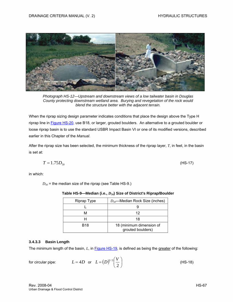
DRAINAGE CRITERIA MANUAL (V. 2) HYDRAULIC STRUCTURES
Photograph HS-12—Upstream and downstream views of a low tailwater basin in Douglas County protecting downstream wetland area. Burying and revegetation of the rock would
blend the structure better with the adjacent terrain.
When the riprap sizing design parameter indicates conditions that place the design above the Type H
riprap line in Figure HS-20, use B18, or larger, grouted boulders. An alternative to a grouted boulder or
loose riprap basin is to use the standard USBR Impact Basin VI or one of its modified versions, described
earlier in this Chapter of the Manual.
After the riprap size has been selected, the minimum thickness of the riprap layer, T, in feet, in the basin
is set at:
5075.1 DT = (HS-17)
in which:
D50 = the median size of the riprap (see Table HS-9.)
Table HS-9—Median (i.e., D50) Size of District's Riprap/Boulder
Riprap Type D50—Median Rock Size (inches) L 9 M 12 H 18
B18 18 (minimum dimension of grouted boulders)
3.4.3.3 Basin Length The minimum length of the basin, L, in Figure HS-19, is defined as being the greater of the following:
for circular pipe: or DL 4= ( ) ⎟⎠⎞
⎜⎝⎛=
22/1 VDL (HS-18)
Rev. 2008-04 HS-67 Urban Drainage & Flood Control District
HYDRAULIC STRUCTURES DRAINAGE CRITERIA MANUAL (V. 2)
for rectangular pipe: or HL 4= ( ) ⎟⎠⎞
⎜⎝⎛=
22/1 VHL (HS-19)
in which:
L = basin length
H = height of rectangular conduit
V = design flow velocity at outlet
D = diameter of circular conduit
3.4.3.4 Basin Width The minimum width, W, of the basin downstream of the pipe’s flared end section is set as follows:
for circular pipes: (HS-20) DW 4=
for rectangular pipe: (HS-21) HwW 4+=
in which,
W = basin width (Figure HS-19)
D = diameter of circular conduit
w = width of rectangular conduit
3.4.3.5 Other Design Requirements All slopes in the pre-shaped riprapped basin are 2H to 1V.
Provide pipe joint fasteners and a structural concrete cutoff wall at the end of the flared end section for a
circular pipe or a headwall with wingwalls and a paved bottom between the walls, both with a cutoff wall
that extends down to a depth of:
BD
T= +2
or BH
T= +2
(HS-22)
in which,
B = cutoff wall depth
D = diameter of circular conduit
T = Equation HS-17
The riprap must be extended up the outlet embankment's slope to the mid-pipe level.
HS-68 2008-04 Urban Drainage & Flood Control District
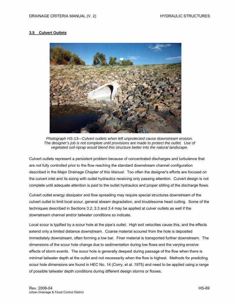
DRAINAGE CRITERIA MANUAL (V. 2) HYDRAULIC STRUCTURES
3.5 Culvert Outlets
Photograph HS-13—Culvert outlets when left unprotected cause downstream erosion. The designer’s job is not complete until provisions are made to protect the outlet. Use of
vegetated soil-riprap would blend this structure better into the natural landscape.
Culvert outlets represent a persistent problem because of concentrated discharges and turbulence that
are not fully controlled prior to the flow reaching the standard downstream channel configuration
described in the Major Drainage Chapter of this Manual. Too often the designer's efforts are focused on
the culvert inlet and its sizing with outlet hydraulics receiving only passing attention. Culvert design is not
complete until adequate attention is paid to the outlet hydraulics and proper stilling of the discharge flows.
Culvert outlet energy dissipator and flow spreading may require special structures downstream of the
culvert outlet to limit local scour, general stream degradation, and troublesome head cutting. Some of the
techniques described in Sections 3.2, 3.3 and 3.4 may be applied at culver outlets as well if the
downstream channel and/or tailwater conditions so indicate.
Local scour is typified by a scour hole at the pipe’s outlet. High exit velocities cause this, and the effects
extend only a limited distance downstream. Coarse material scoured from the hole is deposited
immediately downstream, often forming a low bar. Finer material is transported further downstream. The
dimensions of the scour hole change due to sedimentation during low flows and the varying erosive
effects of storm events. The scour hole is generally deepest during passage of the flow when there is
minimal tailwater depth at the outlet and not necessarily when the flow is highest. Methods for predicting
scour hole dimensions are found in HEC No. 14 (Corry, et al. 1975) and need to be applied using a range
of possible tailwater depth conditions during different design storms or floows.
Rev. 2008-04 HS-69 Urban Drainage & Flood Control District

HYDRAULIC STRUCTURES DRAINAGE CRITERIA MANUAL (V. 2)
General storm degradation, or head cutting, is a phenomenon independent of culvert performance.
Natural causes produce a lowering of the streambed over time. The identification of a degrading stream
is an essential part of the original site investigation. However, high-energy discharges from a culvert can
often cause stream degradation for a limited in distance downstream. Both scour and steam degradation
can occur simultaneously at a culvert outlet.
Various measures described in HEC No. 14 and in this Manual listed below need to be considered to
protect the downstream channel or stream and control culvert outlet flow. It is beyond the scope of this
Manual to provide detailed information about all available controls in HEC No. 14, but the District
encourages the proper application and design as appropriate for the specific site.
1. Colorado State University rigid boundary basin
2. Tumbling flow rectangular section
3. Increased resistance—box culverts
4. Roughness elements—circular culverts
5. USBR Type II
6. USBR Type III
7. USBR Type IV
8. Contra Costa
9. Hook-type energy dissipator
10. Straight drop structure
11. Riprap basins
12. Channel check and drop structures and other energy dissipating and control structures described
earlier in this Chapter
13. Use of properly anchored flared end sections – see Figure HS-19a
HS-70 2008-04 Urban Drainage & Flood Control District
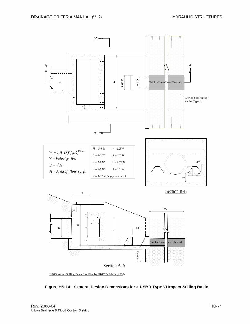
DRAINAGE CRITERIA MANUAL (V. 2) HYDRAULIC STRUCTURES
B
e
e
D W
L
B
t
tb
d
D
H
d
3 - f
t. (m
in.)
W
c
d
e
AA
0.65
D
0.5
D
Buried Soil Riprap ( min. Type L)
Trickle/Low-Flow Channel
Trickle/Low-Flow Channel
Section A-AUSGS Impact Stilling Basin Modified by UDFCD February 2004
1.4 d
f
e e e
d
d/4
Section B-B
H = 3/4 W c = 1/2 W
L = 4/3 W d = 1/6 W
a = 1/2 W e = 1/12 W
b = 3/8 W f = 1/8 W
t = 1/12 W (suggested min.)
[ ]
..,
/,94.2 556.0
ftsqflowofAreaAAD
sftVelocityVgDVDW
==
==
a
Figure HS-14—General Design Dimensions for a USBR Type VI Impact Stilling Basin
Rev. 2008-04 HS-71 Urban Drainage & Flood Control District
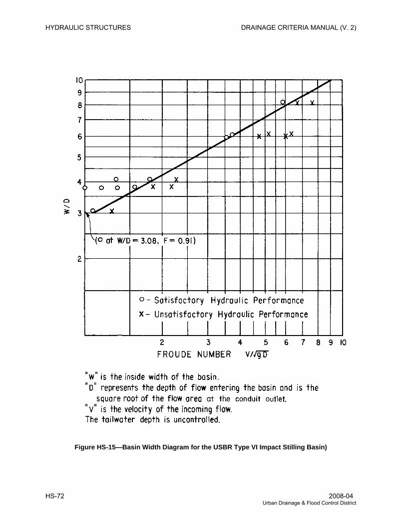
HYDRAULIC STRUCTURES DRAINAGE CRITERIA MANUAL (V. 2)
Figure HS-15—Basin Width Diagram for the USBR Type VI Impact Stilling Basin)
HS-72 2008-04 Urban Drainage & Flood Control District
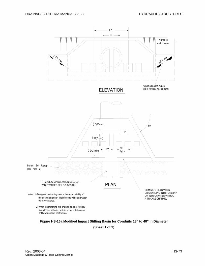
DRAINAGE CRITERIA MANUAL (V. 2) HYDRAULIC STRUCTURES
2 D
34 D(2'max)
34 D(2' min)
34 D(2' min)
18" (typ.)
ELEVATION
PLAN
60°
8"
Varies tomatch slope
max
2.5:1 max
2.5:1
TRICKLE CHANNEL WHEN NEEDED.WIDHT VARIES PER D/S DESIGN.
Adjust slopes to match top of forebay wall or berm.
Buried Soil Riprap (see note 2)
D
18"
Notes: 1) Design of reinforcing steel is the responsibility of the desing engineer. Reinforce to withstand water earh pressueres.
2) When dischargning into channel and not forebay install Type M buried soil riprap for a distance of 3*D downstream of structure.
ELIMINATE SILLS WHENDISCHARGING INTO FOREBAY OR INTO CHANNLE WITHOUT A TRICKLE CHANNEL
Figure HS-16a Modified Impact Stilling Basin for Conduits 18” to 48” in Diameter
(Sheet 1 of 2)
Rev. 2008-04 HS-73 Urban Drainage & Flood Control District
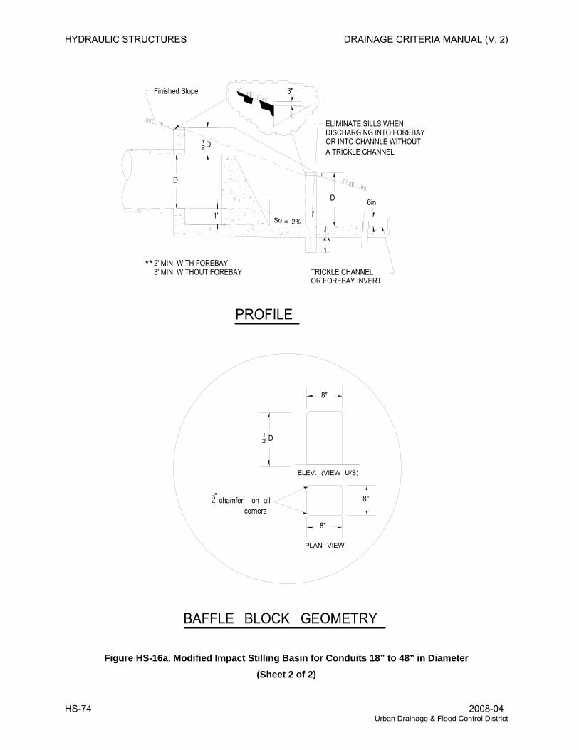
HYDRAULIC STRUCTURES DRAINAGE CRITERIA MANUAL (V. 2)
D
1'
12 D
D
8"
8"
12 D
8"
PROFILE
BAFFLE BLOCK GEOMETRY
ELEV. (VIEW U/S)
PLAN VIEW
6in
Finished Slope
So = 2%
cornersall on chamfer "
43
3"
**
ELIMINATE SILLS WHENDISCHARGING INTO FOREBAY OR INTO CHANNLE WITHOUT A TRICKLE CHANNEL
TRICKLE CHANNELOR FOREBAY INVERT
**2' MIN. WITH FOREBAY3' MIN. WITHOUT FOREBAY
Figure HS-16a. Modified Impact Stilling Basin for Conduits 18” to 48” in Diameter (Sheet 2 of 2)
HS-74 2008-04 Urban Drainage & Flood Control District
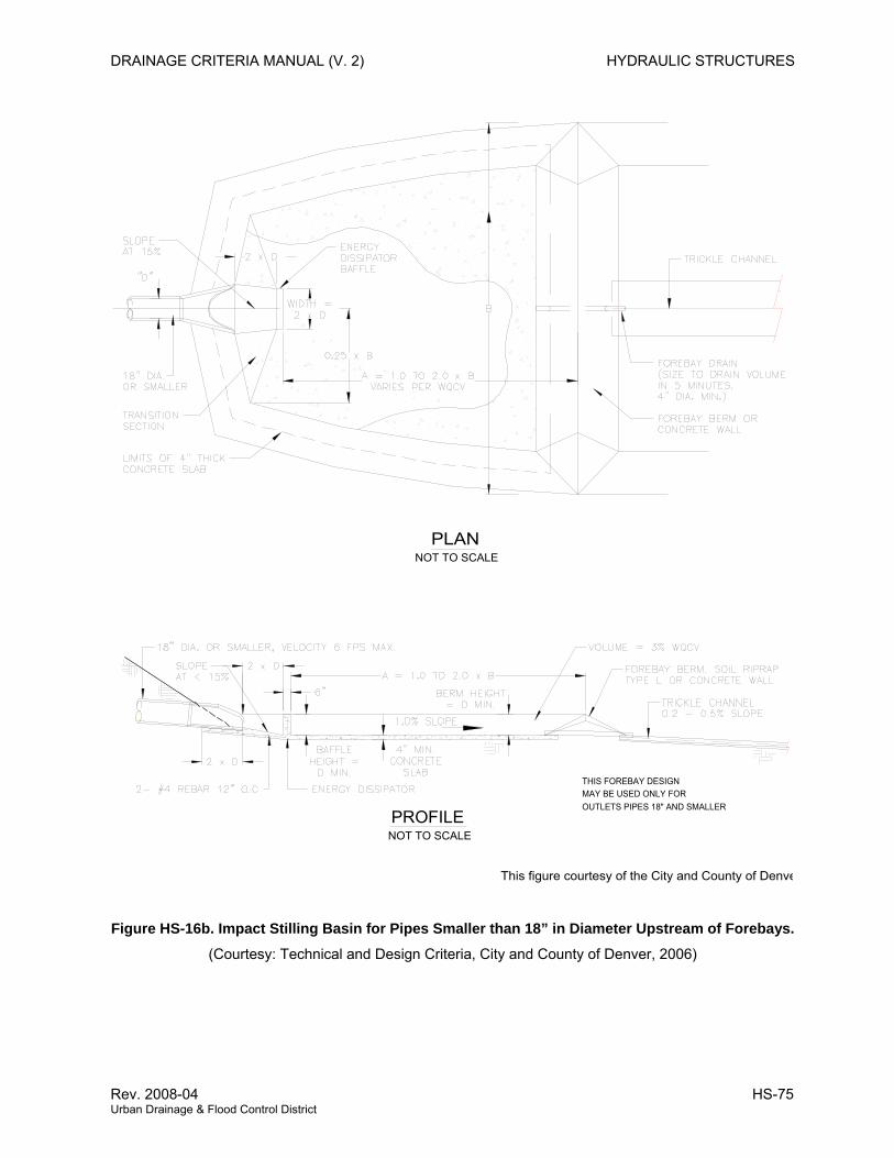
DRAINAGE CRITERIA MANUAL (V. 2) HYDRAULIC STRUCTURES
MAY BE USED ONLY FOROUTLETS PIPES 18" AND SMALLER
PROFILENOT TO SCALE
THIS FOREBAY DESIGN
PLANNOT TO SCALE
This figure courtesy of the City and County of Denve
Figure HS-16b. Impact Stilling Basin for Pipes Smaller than 18” in Diameter Upstream of Forebays.
(Courtesy: Technical and Design Criteria, City and County of Denver, 2006)
Rev. 2008-04 HS-75 Urban Drainage & Flood Control District
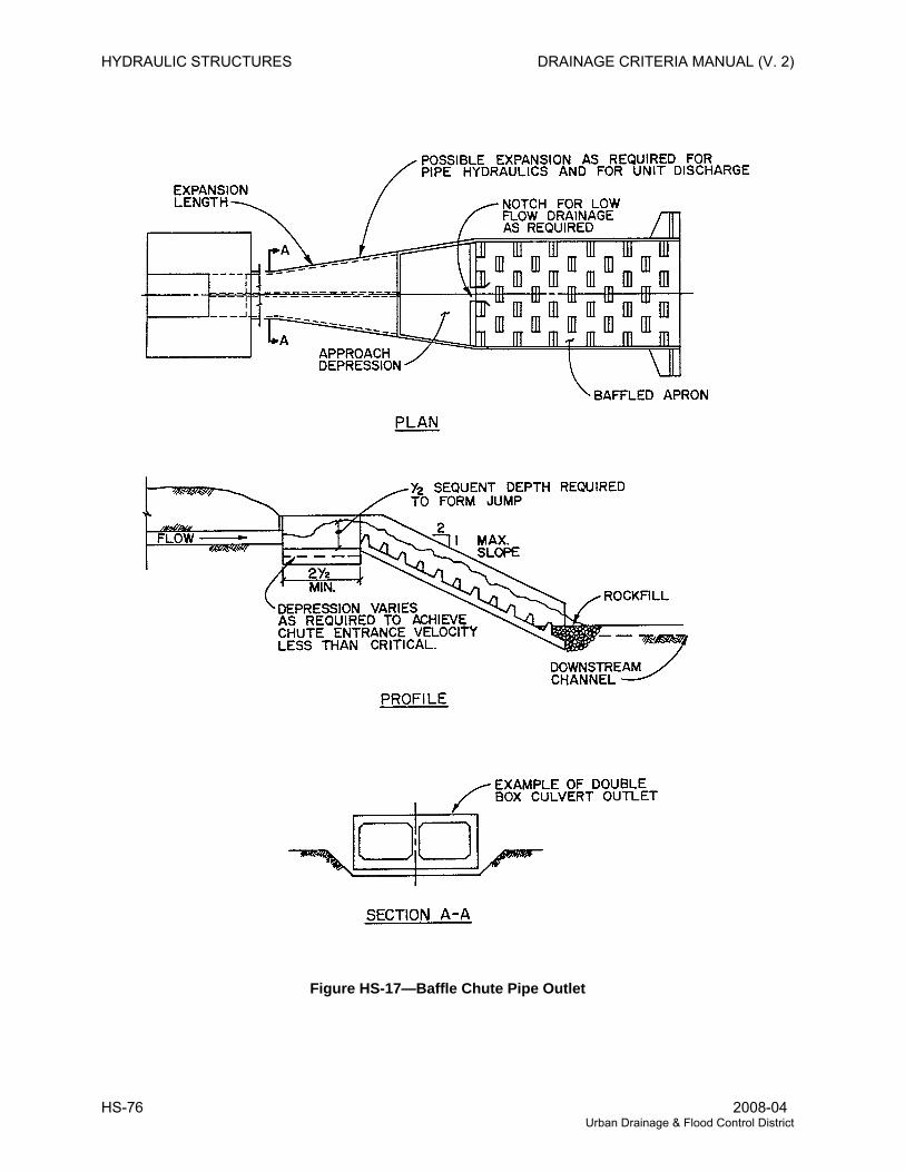
HYDRAULIC STRUCTURES DRAINAGE CRITERIA MANUAL (V. 2)
Figure HS-17—Baffle Chute Pipe Outlet
HS-76 2008-04 Urban Drainage & Flood Control District
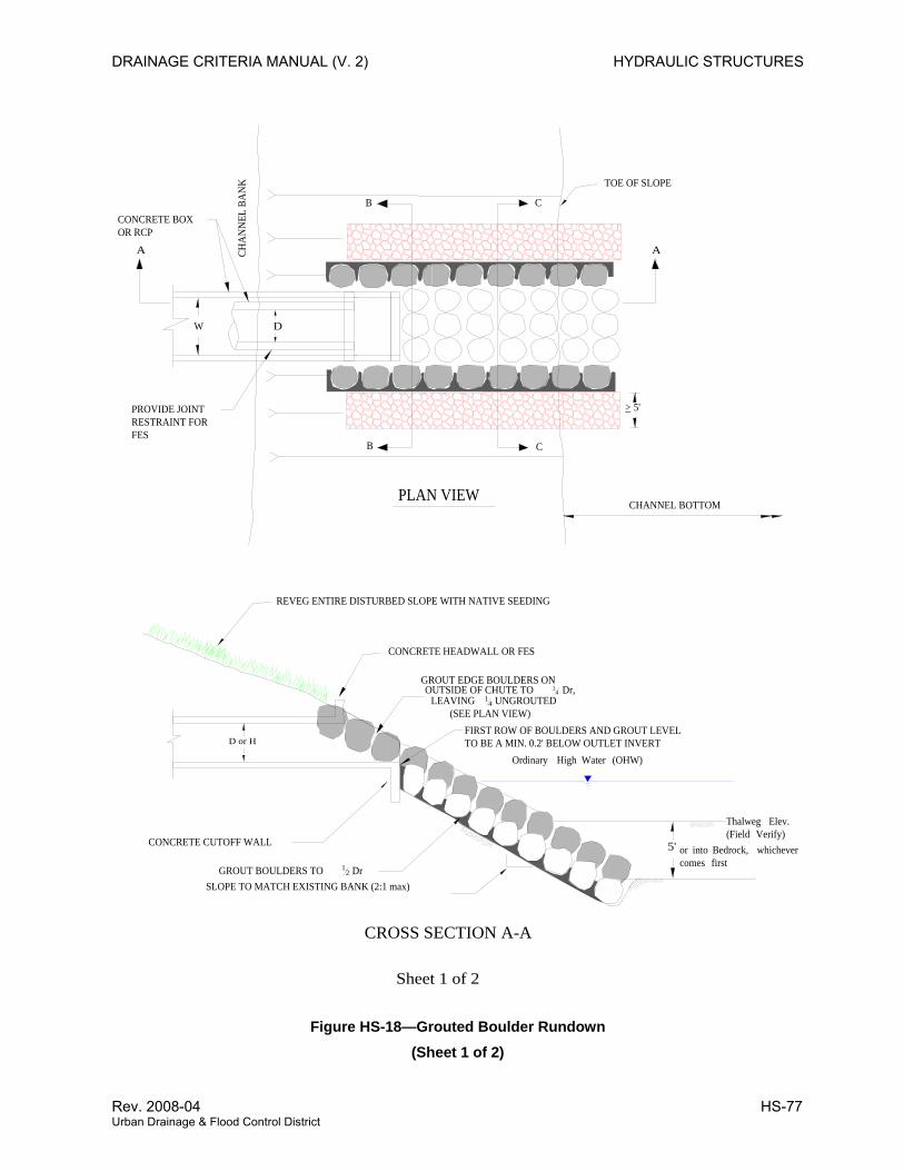
DRAINAGE CRITERIA MANUAL (V. 2) HYDRAULIC STRUCTURES
GROUT BOULDERS TO 12 Dr
Ordinary High Water (OHW)
5'
REVEG ENTIRE DISTURBED SLOPE WITH NATIVE SEEDING
Thalweg Elev.(Field Verify)
CONCRETE CUTOFF WALL
PLAN VIEW
CROSS SECTION A-A
W
D or H
B C
CB
AA
CONCRETE HEADWALL OR FES
CHA
NN
EL B
AN
K TOE OF SLOPE
D
Sheet 1 of 2
SLOPE TO MATCH EXISTING BANK (2:1 max)
> 5'
or into Bedrock, whichever comes first
GROUT EDGE BOULDERS ON OUTSIDE OF CHUTE TO 34 Dr,
LEAVING 14 UNGROUTED
(SEE PLAN VIEW)
CHANNEL BOTTOM
PROVIDE JOINTRESTRAINT FORFES
FIRST ROW OF BOULDERS AND GROUT LEVELTO BE A MIN. 0.2' BELOW OUTLET INVERT
CONCRETE BOXOR RCP
Figure HS-18—Grouted Boulder Rundown (Sheet 1 of 2)
Rev. 2008-04 HS-77 Urban Drainage & Flood Control District
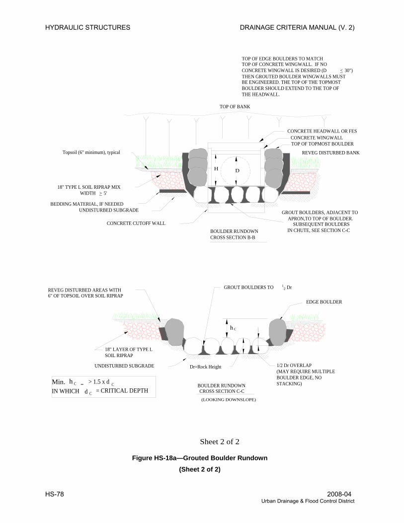
HYDRAULIC STRUCTURES DRAINAGE CRITERIA MANUAL (V. 2)
CONCRETE HEADWALL OR FES
REVEG DISTURBED BANK
18" TYPE L SOIL RIPRAP MIXWIDTH > 5'
BOULDER RUNDOWNCROSS SECTION B-B
GROUT BOULDERS TO 12 Dr REVEG DISTURBED AREAS WITH
6" OF TOPSOIL OVER SOIL RIPRAP
BOULDER RUNDOWNCROSS SECTION C-C
UNDISTURBED SUBGRADE
UNDISTURBED SUBGRADE
CONCRETE CUTOFF WALL
h C
h C > 1.5 x d CMin.IN WHICH = CRITICAL DEPTH d C
18" LAYER OF TYPE L
TOP OF BANK
H D
EDGE BOULDER
Sheet 2 of 2
GROUT BOULDERS, ADJACENT TOAPRON,TO TOP OF BOULDER.
SUBSEQUENT BOULDERSIN CHUTE, SEE SECTION C-C
Topsoil (6" minimum), typical
BEDDING MATERIAL, IF NEEDED
Dr=Rock Height
TOP OF EDGE BOULDERS TO MATCHTOP OF CONCRETE WINGWALL. IF NO CONCRETE WINGWALL IS DESIRED (D < 30") THEN GROUTED BOULDER WINGWALLS MUSTBE ENGINEERED. THE TOP OF THE TOPMOSTBOULDER SHOULD EXTEND TO THE TOP OFTHE HEADWALL.
CONCRETE WINGWALL
(LOOKING DOWNSLOPE)
TOP OF TOPMOST BOULDER
SOIL RIPRAP
1/2 Dr OVERLAP(MAY REQUIRE MULTIPLEBOULDER EDGE, NOSTACKING)
Figure HS-18a—Grouted Boulder Rundown
(Sheet 2 of 2)
HS-78 2008-04 Urban Drainage & Flood Control District
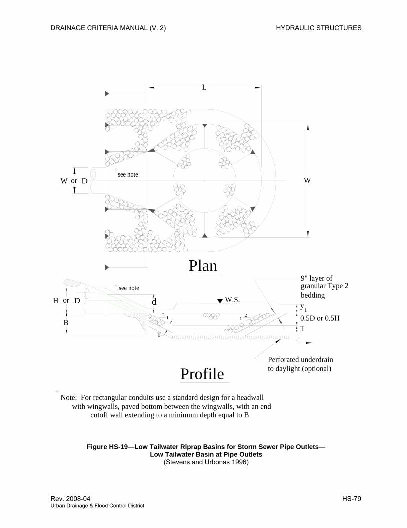
DRAINAGE CRITERIA MANUAL (V. 2) HYDRAULIC STRUCTURES
cutoff wall extending to a minimum depth equal to Bwith wingwalls, paved bottom between the wingwalls, with an end
Note: For rectangular conduits use a standard design for a headwall
L
or
B
H
see note
D d2
T
1
see noteDor
Plan
Perforated underdrainto daylight (optional)
W.S.
Profile
12
9" layer ofgranular Type 2
0.5D or 0.5H
beddingy
T
t
WW
Figure HS-19—Low Tailwater Riprap Basins for Storm Sewer Pipe Outlets— Low Tailwater Basin at Pipe Outlets
(Stevens and Urbonas 1996)
Rev. 2008-04 HS-79 Urban Drainage & Flood Control District
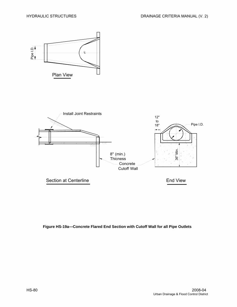
HYDRAULIC STRUCTURES DRAINAGE CRITERIA MANUAL (V. 2)
Plan View
Pipe
I.D
.
Section at Centerline End View
CL
Install Joint Restraints
8" (min.) Thicness Concrete Cutoff Wall
18"to
12"
Pipe I.D.
36" M
in.
Figure HS-19a—Concrete Flared End Section with Cutoff Wall for all Pipe Outlets
HS-80 2008-04 Urban Drainage & Flood Control District
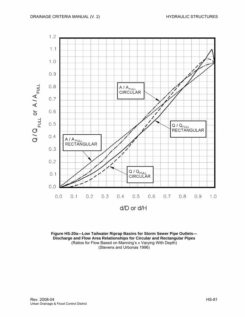
DRAINAGE CRITERIA MANUAL (V. 2) HYDRAULIC STRUCTURES
Figure HS-20a—Low Tailwater Riprap Basins for Storm Sewer Pipe Outlets— Discharge and Flow Area Relationships for Circular and Rectangular Pipes
(Ratios for Flow Based on Manning’s n Varying With Depth) (Stevens and Urbonas 1996)
Rev. 2008-04 HS-81 Urban Drainage & Flood Control District
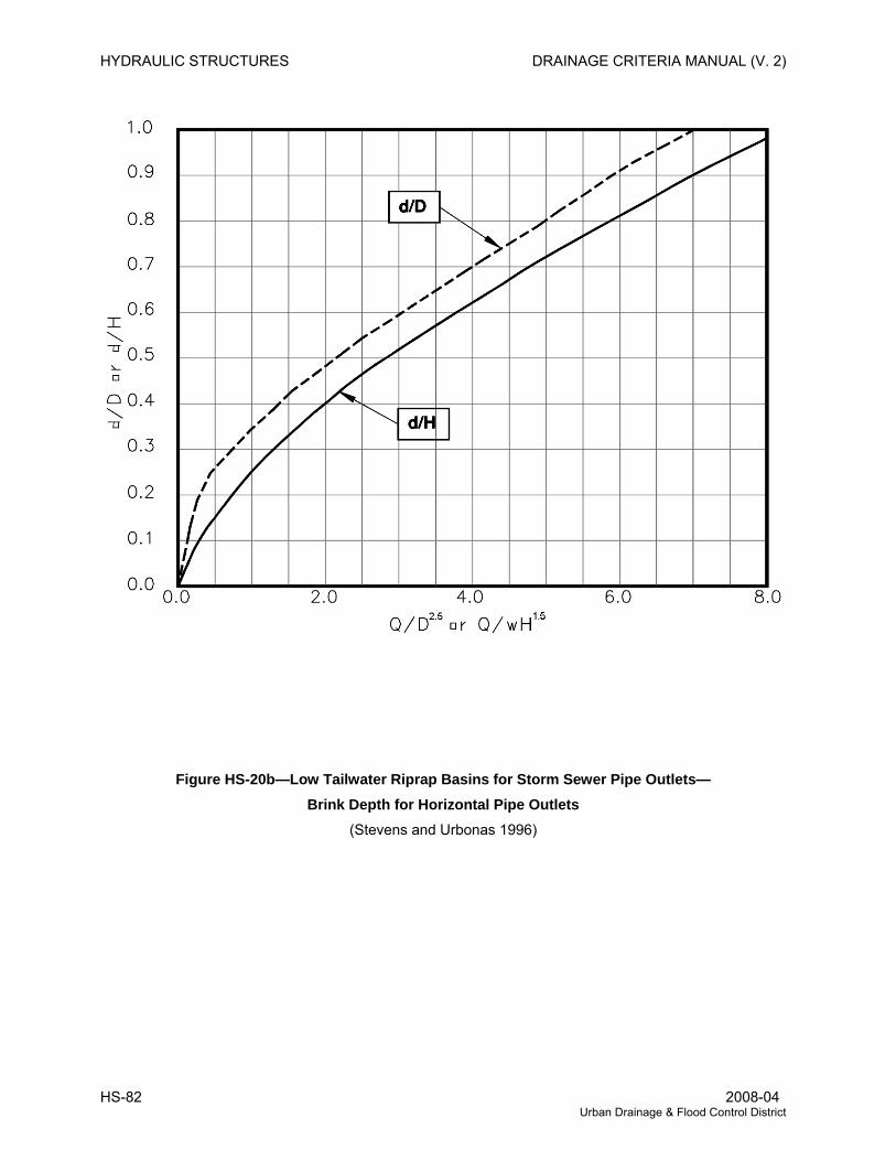
HYDRAULIC STRUCTURES DRAINAGE CRITERIA MANUAL (V. 2)
Figure HS-20b—Low Tailwater Riprap Basins for Storm Sewer Pipe Outlets— Brink Depth for Horizontal Pipe Outlets
(Stevens and Urbonas 1996)
HS-82 2008-04 Urban Drainage & Flood Control District
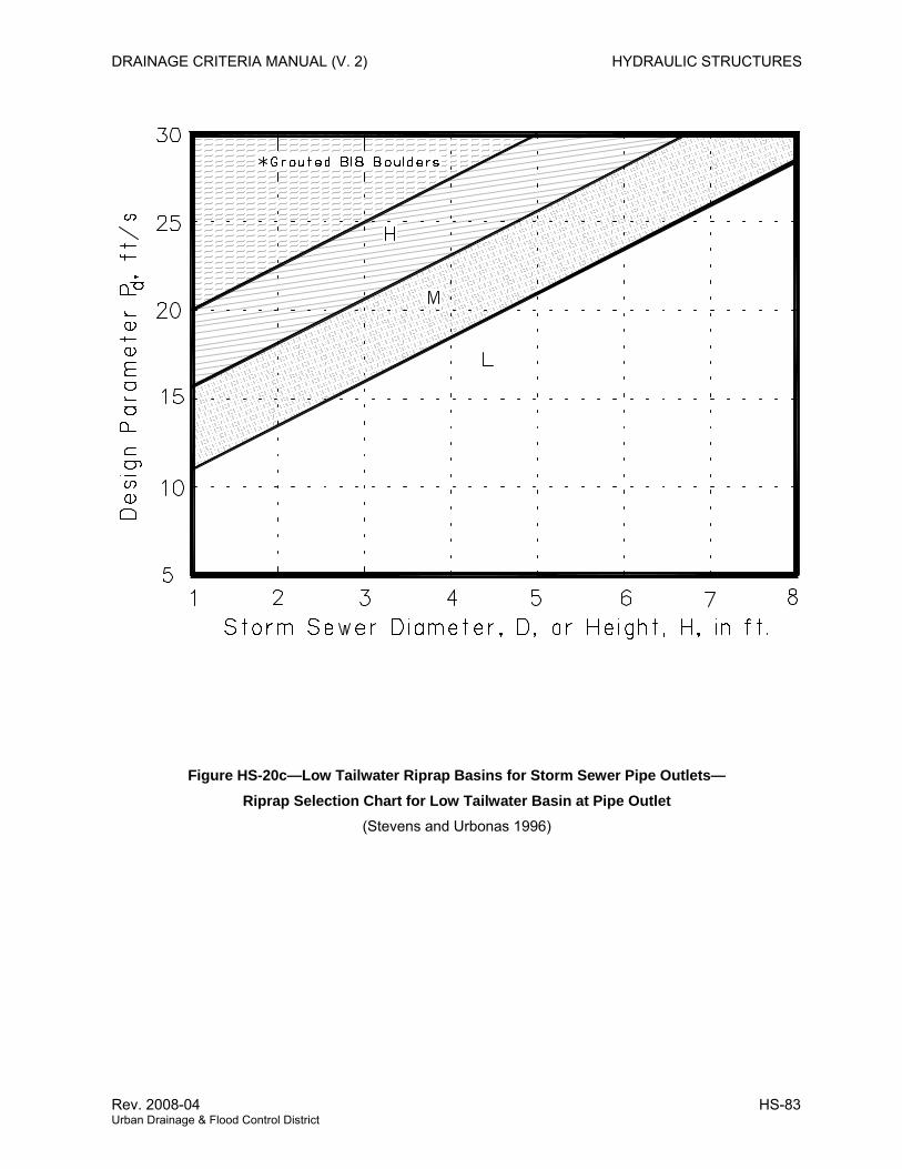
DRAINAGE CRITERIA MANUAL (V. 2) HYDRAULIC STRUCTURES
Figure HS-20c—Low Tailwater Riprap Basins for Storm Sewer Pipe Outlets— Riprap Selection Chart for Low Tailwater Basin at Pipe Outlet
(Stevens and Urbonas 1996)
Rev. 2008-04 HS-83 Urban Drainage & Flood Control District
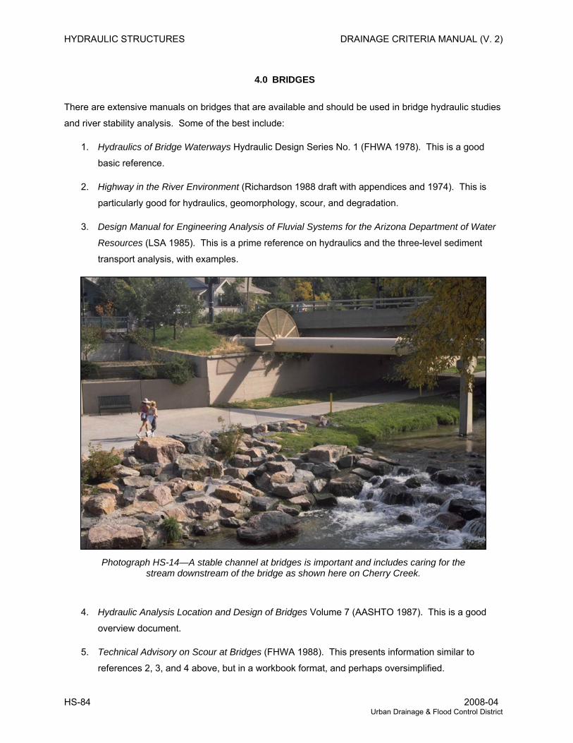
HYDRAULIC STRUCTURES DRAINAGE CRITERIA MANUAL (V. 2)
4.0 BRIDGES
There are extensive manuals on bridges that are available and should be used in bridge hydraulic studies
and river stability analysis. Some of the best include:
1. Hydraulics of Bridge Waterways Hydraulic Design Series No. 1 (FHWA 1978). This is a good
basic reference.
2. Highway in the River Environment (Richardson 1988 draft with appendices and 1974). This is
particularly good for hydraulics, geomorphology, scour, and degradation.
3. Design Manual for Engineering Analysis of Fluvial Systems for the Arizona Department of Water
Resources (LSA 1985). This is a prime reference on hydraulics and the three-level sediment
transport analysis, with examples.
Photograph HS-14—A stable channel at bridges is important and includes caring for the stream downstream of the bridge as shown here on Cherry Creek.
4. Hydraulic Analysis Location and Design of Bridges Volume 7 (AASHTO 1987). This is a good
overview document.
5. Technical Advisory on Scour at Bridges (FHWA 1988). This presents information similar to
references 2, 3, and 4 above, but in a workbook format, and perhaps oversimplified.
HS-84 2008-04 Urban Drainage & Flood Control District
DRAINAGE CRITERIA MANUAL (V. 2) HYDRAULIC STRUCTURES
Bridges are required across nearly all open urban channels sooner or later and, therefore, sizing the
bridge openings is of paramount importance. Open channels with improperly designed bridges will either
have excessive scour or deposition or not be able to carry the design flow.
4.1 Basic Criteria
Bridge openings should be designed to have as little effect on the flow characteristics as reasonable,
consistent with good bridge design and economics. However, in regard to supercritical flow with a lined
channel, the bridge should not affect the flow at all—that is, there should be no projections into the design
water prism that could create a hydraulic jump or flow instability in form of reflecting and standing waves.
4.1.1 Design Approach The method of planning for bridge openings must include water surface profiles and hydraulic gradient
analyses of the channel for the major storm runoff. Once this hydraulic gradient is established without the
bridge, the maximum reasonable effect on the channel flow by the bridge should be determined. In urban
cases this should not exceed a backwater effect of more than 6 to 12 inches.
Velocities through the bridge and downstream of the bridge must receive consideration in choosing the
bridge opening. Velocities exceeding those permissible will require special protection of the bottom and
banks.
For supercritical flow, the clear bridge opening should permit the flow to pass under unimpeded and
unchanged in cross section.
4.1.2 Bridge Opening Freeboard The distance between the design flow water surface and the bottom of the bridge deck will vary from case
to case. However, the debris that may be expected must receive full consideration in setting the
freeboard. Freeboard may vary from several feet to minus several feet. There are no general rules.
Each case must be studied separately. In larger waterways, streams and on rivers where large floating
debris is likely, at least a 3-foot freeboard during a 100-year flood should be considered.
Bridges that are securely anchored to foundations and designed to withstand the dynamic forces of the
flowing water might, in some cases, be designed without freeboard.
4.2 Hydraulic Analysis
The hydraulic analysis procedures described below are suitable, although alternative methods such as
FHWA HY-4 or HEC-RAS are acceptable, as well.
The design of a bridge opening generally determines the overall length of the bridge. The length affects
the final cost of the bridge. The hydraulic engineering in the design of bridges has more impact on the
bridge cost than does the structural design. Good hydraulic engineering is necessary for good bridge
design (FHWA 1978, Richardson 1974 and 1988).
Rev. 2008-04 HS-85 Urban Drainage & Flood Control District
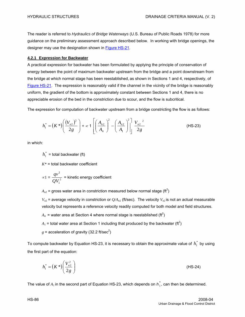
HYDRAULIC STRUCTURES DRAINAGE CRITERIA MANUAL (V. 2)
The reader is referred to Hydraulics of Bridge Waterways (U.S. Bureau of Public Roads 1978) for more
guidance on the preliminary assessment approach described below. In working with bridge openings, the
designer may use the designation shown in Figure HS-21.
4.2.1 Expression for Backwater A practical expression for backwater has been formulated by applying the principle of conservation of
energy between the point of maximum backwater upstream from the bridge and a point downstream from
the bridge at which normal stage has been reestablished, as shown in Sections 1 and 4, respectively, of
Figure HS-21. The expression is reasonably valid if the channel in the vicinity of the bridge is reasonably
uniform, the gradient of the bottom is approximately constant between Sections 1 and 4, there is no
appreciable erosion of the bed in the constriction due to scour, and the flow is subcritical.
The expression for computation of backwater upstream from a bridge constricting the flow is as follows:
( ) ( )⎟⎟⎠
⎞⎜⎜⎝
⎛=
gV
Kh n
2*
22*
1 + ∝ 1 ⎥⎥⎦
⎤
⎢⎢⎣
⎡⎟⎟⎠
⎞⎜⎜⎝
⎛−⎟⎟
⎠
⎞⎜⎜⎝
⎛2
1
22
4
2
AA
AA nn
gVn
2
22 (HS-23)
in which:
*1h = total backwater (ft)
K* = total backwater coefficient
∝1 = 21
2
QVqv
= kinetic energy coefficient
An2 = gross water area in constriction measured below normal stage (ft2)
Vn2 = average velocity in constriction or Q/An2 (ft/sec). The velocity Vn2 is not an actual measurable
velocity but represents a reference velocity readily computed for both model and field structures.
A4 = water area at Section 4 where normal stage is reestablished (ft2)
A1 = total water area at Section 1 including that produced by the backwater (ft2)
g = acceleration of gravity (32.2 ft/sec2)
To compute backwater by Equation HS-23, it is necessary to obtain the approximate value of by using
the first part of the equation:
*1h
( ) ⎟⎟⎠
⎞⎜⎜⎝
⎛=
gV
Kh n
2*
22*
1 (HS-24)
The value of A1 in the second part of Equation HS-23, which depends on h , can then be determined. *1
HS-86 2008-04 Urban Drainage & Flood Control District
DRAINAGE CRITERIA MANUAL (V. 2) HYDRAULIC STRUCTURES
This part of the expression represents the difference in kinetic energy between Sections 4 and 1,
expressed in terms of the velocity head g
Vn
2
22 . Equation HS-24 may appear cumbersome, but it was set
up as shown to permit omission of the second part when the difference in kinetic energy between
Sections 4 and 1 is small enough to be insignificant in the final result.
To permit the designer to readily recognize cases in which the kinetic energy term may be ignored, the
following guides are provided:
>M 0.7, where M = bridge opening ratio
72 <nV ft/sec
( ) 5.02
*22 <⎟⎟⎠
⎞⎜⎜⎝
⎛g
VK n ft
If values meet all three conditions, the backwater obtained from Equation HS-24 can be considered
sufficiently accurate. Should one or more of the values not meet the conditions set forth, it is advisable to
use Equation HS-23 in its entirety. The use of the guides is further demonstrated in the examples given
in FHWA (1978) that should be used in all bridge design work.
4.2.2 Backwater Coefficient The value of the overall backwater coefficient K*, which was determined experimentally, varies with:
1. Stream constriction as measured by bridge opening ratio, M.
2. Type of bridge abutment: wingwall, spill through, etc.
3. Number, size, shape, and orientation of piers in the constriction.
4. Eccentricity, or asymmetric position of bridge with the floodplains.
5. Skew (bridge crosses floodplain at other than 90 degree angle).
The overall backwater coefficient K* consists of a base curve coefficient, Kb, to which are added
incremental coefficients to account for the effect of piers, eccentricity, and skew. The value of K* is
primarily dependent on the degree of constriction of the flow but also changes to a limited degree with the
other factors.
4.2.3 Effect of M and Abutment Shape (Base Curves) Figure HS-22 shows the base curve for backwater coefficient, Kb, plotted with respect to the opening ratio,
M, for several wingwall abutments and a vertical wall type. Note how the coefficient Kb increases with
Rev. 2008-04 HS-87 Urban Drainage & Flood Control District
HYDRAULIC STRUCTURES DRAINAGE CRITERIA MANUAL (V. 2)
channel constriction. The several curves represent different angles of wingwalls as can be identified by
the accompanying sketches; the lower curves represent the better hydraulic shapes.
Figure HS-23 shows the relation between the backwater coefficient, Kb, and M for spill-through abutments
for three embankment slopes. A comparison of the three curves indicates that the coefficient is little
affected by embankment slope. Figures HS-22 and HS-23 are “base curves” and Kb is referred to as the
“base curve coefficient.” The base curve coefficients apply to normal crossings for specific abutment
shapes but do not include the effect of piers, eccentricity, or skew.
4.2.4 Effect of Piers (Normal Crossings) The effect on the backwater from introduction of piers in a bridge constriction has been treated as an
incremental backwater coefficient designated ΔKp, which is added to the base curve coefficient when
piers are a factor. The value of the incremental backwater coefficient, ΔKp, is dependent on the ratio that
the area of the piers bears to the gross area of the bridge opening, the type of piers (or piling in the case
of pile bents), the value of the bridge opening ratio, M, and the angularity of the piers with the direction of
flood flow. The ratio of the water area occupied by piers, Ap, to the gross water area of the constriction,
An2, both based on the normal water surface, has been assigned the letter J. In computing the gross
water area, An2, the presence of piers in the constriction is ignored. The incremental backwater coefficient
for the more common types of piers and pile bents can be obtained from Figure HS-24. The procedure is
to enter Chart A, Figure HS-24, with the proper value of J and read ΔK and obtain the correction factor σ
from Chart B, Figure HS-24, for opening ratios other than unity. The incremental backwater coefficient is
then
Δ Kp = Δ Kσ (HS-25)
The incremental backwater coefficients for piers can, for all practical purposes, be considered
independent of diameter, width, or spacing but should be increased if there are more than 5 piles in a
bent. A bent with 10 piles should be given a value of ΔKp about 20% higher than those shown for bents
with 5 piles. If there is a good possibility of trash collecting on the piers, it is advisable to use a value
greater than the pier width to include the trash. For a normal crossing with piers, the total backwater
coefficient becomes:
K* = Kb (Figures HS-22 or HS-23) + ΔKp (Figure HS-24) (HS-26)
4.3 Design Procedure
The following is a brief step-by-step outline for determination of backwater produced by a bridge
constriction:
1. Determine the magnitude and frequency of the discharge for which the bridge is to be designed.
HS-88 2008-04 Urban Drainage & Flood Control District
DRAINAGE CRITERIA MANUAL (V. 2) HYDRAULIC STRUCTURES
2. Determine the stage of the stream at the bridge site for the design discharge.
3. Plot representative cross section of stream for design discharge at Section 1, if not already done
under Step 2. If the stream channel is essentially straight and the cross section substantially
uniform in the vicinity of the bridge, the natural cross section of the stream at the bridge site may
be used for this purpose.
4. Subdivide the above cross section according to marked changes in depth of flow and roughness.
Assign values of Manning's roughness coefficient, n, to each subsection. Careful judgment is
necessary in selecting these values.
5. Compute conveyance and then discharge in each subsection.
6. Determine the value of the kinetic energy coefficient.
7. Plot the natural cross section under the proposed bridge based on normal water surface for
design discharge and compute the gross water area (including area occupied by piers).
8. Compute the bridge opening ratio, M, observing modified procedure for skewed crossings.
9. Obtain the value of Kb from the appropriate base curve.
10. If piers are involved, compute the value of J and obtain the incremental coefficient, ΔKp.
11. If eccentricity is severe, compute the value of eccentricity and obtain the incremental coefficient,
ΔKe (FHWA 1978).
12. If a skewed crossing is involved, observe proper procedure in previous steps, then obtain the
incremental coefficient, ΔKs, for proper abutment type.
13. Determine the total backwater coefficient, K*, by adding incremental coefficients to the base
curve coefficient, Kb.
14. Compute the backwater by Equation HS-23.
15. Determine the distance upstream to where the backwater effect is negligible.
Detailed steps illustrated by examples are presented in Hydraulics of Bridge Waterways (FHWA 1978).
4.4 Inadequate Openings
The engineer will often encounter existing bridges and culverts that have been designed for storms
having return periods less than 100 years. In addition, bridges will be encountered which have been
improperly designed. Often the use of the orifice formula will provide a quick determination of the
adequacy or inadequacy of a bridge opening:
Rev. 2008-04 HS-89 Urban Drainage & Flood Control District
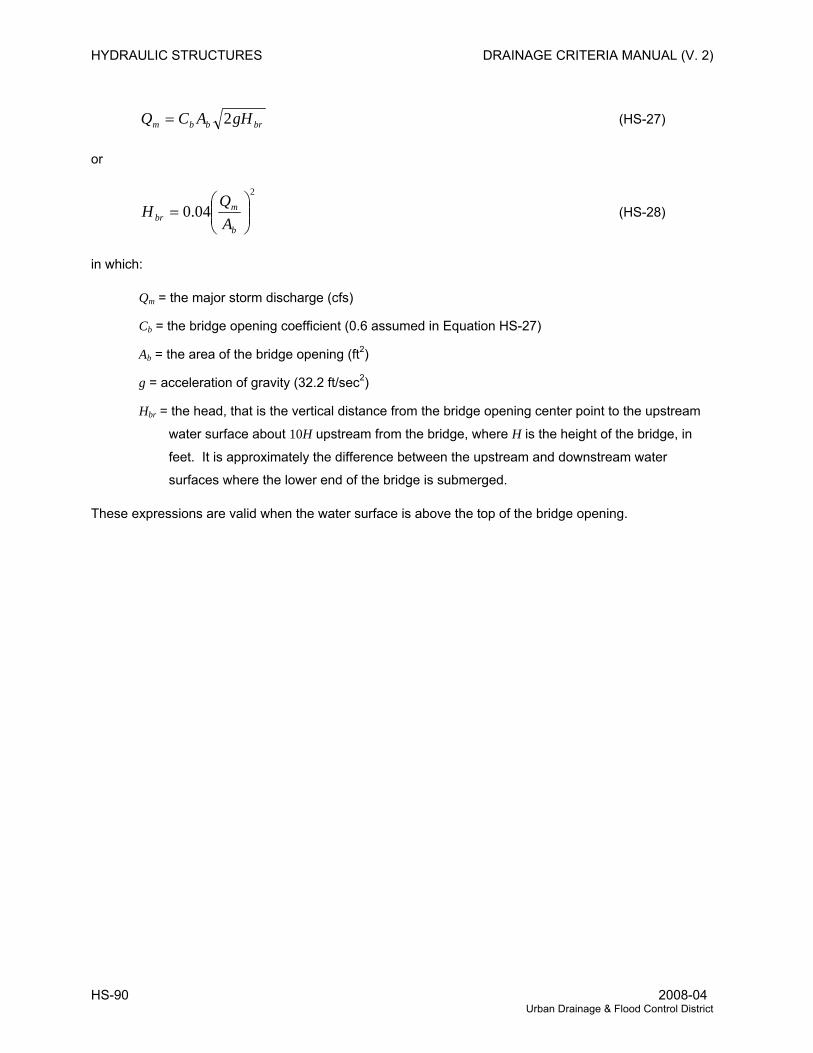
HYDRAULIC STRUCTURES DRAINAGE CRITERIA MANUAL (V. 2)
brbbm gHACQ 2= (HS-27)
or
2
04.0 ⎟⎟⎠
⎞⎜⎜⎝
⎛=
b
mbr A
QH (HS-28)
in which:
Qm = the major storm discharge (cfs)
Cb = the bridge opening coefficient (0.6 assumed in Equation HS-27)
Ab = the area of the bridge opening (ft2)
g = acceleration of gravity (32.2 ft/sec2)
Hbr = the head, that is the vertical distance from the bridge opening center point to the upstream
water surface about 10H upstream from the bridge, where H is the height of the bridge, in
feet. It is approximately the difference between the upstream and downstream water
surfaces where the lower end of the bridge is submerged.
These expressions are valid when the water surface is above the top of the bridge opening.
HS-90 2008-04 Urban Drainage & Flood Control District
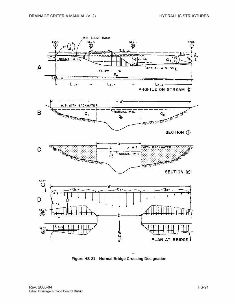
DRAINAGE CRITERIA MANUAL (V. 2) HYDRAULIC STRUCTURES
Figure HS-21—Normal Bridge Crossing Designation
Rev. 2008-04 HS-91 Urban Drainage & Flood Control District
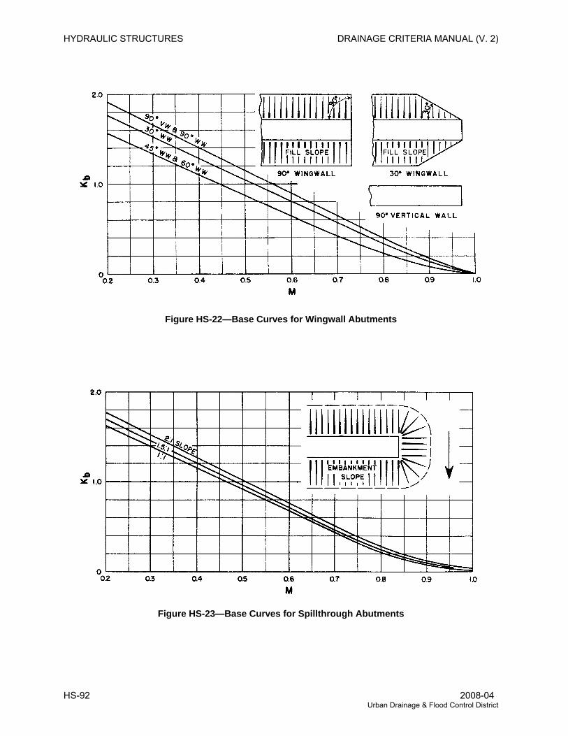
HYDRAULIC STRUCTURES DRAINAGE CRITERIA MANUAL (V. 2)
Figure HS-22—Base Curves for Wingwall Abutments
Figure HS-23—Base Curves for Spillthrough Abutments
HS-92 2008-04 Urban Drainage & Flood Control District
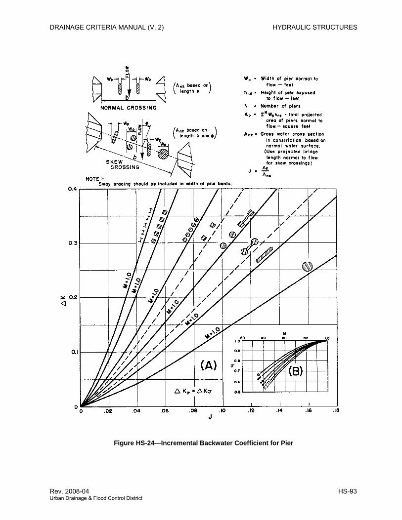
DRAINAGE CRITERIA MANUAL (V. 2) HYDRAULIC STRUCTURES
Figure HS-24—Incremental Backwater Coefficient for Pier
Rev. 2008-04 HS-93 Urban Drainage & Flood Control District
HYDRAULIC STRUCTURES DRAINAGE CRITERIA MANUAL (V. 2)
5.0 TRANSITIONS AND CONSTRICTIONS
5.1 Introduction
The purpose of this section is to outline typical design procedures for transition and constriction structures
that are commonly encountered in the District’s flood control and drainage projects. There are numerous
references that can be useful for detailed analysis of different project objectives or site conditions (Rouse
1949, Chow 1959, USACE 1970 and 1982, FHWA 2000, SCS 1977). This topic is also addressed in
MAJOR DRAINAGE, under riprap-lined channels.
5.2 Transition Analysis
5.2.1 Subcritical Transitions Transitions for subcritical flow frequently involve localized structures or bank lining configurations that
allow change in the cross section and produce a water surface profile based on gradually varied flow.
The energy lost through a transition is a function of the friction, eddy currents and turbulence. The intent
is often to minimize friction losses and/or erosional tendencies. Examples include transitions between
trapezoidal and rectangular sections, modest transitions at bridges where little change takes place in the
cross section, or slight encroachments into a channel to allow for utilities. Transitions can be handled
with various structures, including concrete facilities (Figure HS-25) and riprap-lined channel reaches (see
MAJOR DRAINAGE).
Standard water surface profile analysis is applied, with the addition of an energy loss at the transition.
The loss is expressed as a function of the change in velocity head occurring across the contraction or
expansion transition (from upstream to downstream locations). Figure HS-25 illustrates some of these
transitions with basic design guidelines. Loss coefficients shown in Table HS-10 are applied to the
difference in velocity head, as shown in Equation HS-29.
Analysis of transitions requires careful water surface profile analysis including verification of effective
channel hydraulic controls. It is not uncommon to have a transition that is first thought to be performing in
a subcritical mode, subsequently found to produce a supercritical profile with a hydraulic jump.
Energy Loss (ft) = Coefficient (hv1 – hv2)
in which:
( ) ⎟⎟⎠
⎞⎜⎜⎝
⎛−=−
gV
gV
hh vv 22
22
21
21 (HS-29)
V1 = flow velocity upstream of transition
V2 = flow velocity downstream of transition
HS-94 2008-04 Urban Drainage & Flood Control District
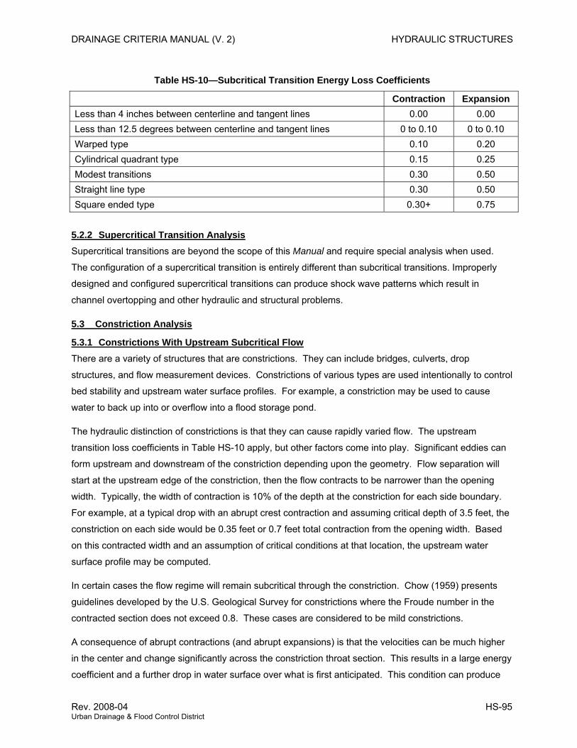
DRAINAGE CRITERIA MANUAL (V. 2) HYDRAULIC STRUCTURES
Table HS-10—Subcritical Transition Energy Loss Coefficients
Contraction Expansion Less than 4 inches between centerline and tangent lines 0.00 0.00 Less than 12.5 degrees between centerline and tangent lines 0 to 0.10 0 to 0.10 Warped type 0.10 0.20 Cylindrical quadrant type 0.15 0.25 Modest transitions 0.30 0.50 Straight line type 0.30 0.50 Square ended type 0.30+ 0.75
5.2.2 Supercritical Transition Analysis Supercritical transitions are beyond the scope of this Manual and require special analysis when used.
The configuration of a supercritical transition is entirely different than subcritical transitions. Improperly
designed and configured supercritical transitions can produce shock wave patterns which result in
channel overtopping and other hydraulic and structural problems.
5.3 Constriction Analysis
5.3.1 Constrictions With Upstream Subcritical Flow There are a variety of structures that are constrictions. They can include bridges, culverts, drop
structures, and flow measurement devices. Constrictions of various types are used intentionally to control
bed stability and upstream water surface profiles. For example, a constriction may be used to cause
water to back up into or overflow into a flood storage pond.
The hydraulic distinction of constrictions is that they can cause rapidly varied flow. The upstream
transition loss coefficients in Table HS-10 apply, but other factors come into play. Significant eddies can
form upstream and downstream of the constriction depending upon the geometry. Flow separation will
start at the upstream edge of the constriction, then the flow contracts to be narrower than the opening
width. Typically, the width of contraction is 10% of the depth at the constriction for each side boundary.
For example, at a typical drop with an abrupt crest contraction and assuming critical depth of 3.5 feet, the
constriction on each side would be 0.35 feet or 0.7 feet total contraction from the opening width. Based
on this contracted width and an assumption of critical conditions at that location, the upstream water
surface profile may be computed.
In certain cases the flow regime will remain subcritical through the constriction. Chow (1959) presents
guidelines developed by the U.S. Geological Survey for constrictions where the Froude number in the
contracted section does not exceed 0.8. These cases are considered to be mild constrictions.
A consequence of abrupt contractions (and abrupt expansions) is that the velocities can be much higher
in the center and change significantly across the constriction throat section. This results in a large energy
coefficient and a further drop in water surface over what is first anticipated. This condition can produce
Rev. 2008-04 HS-95 Urban Drainage & Flood Control District
HYDRAULIC STRUCTURES DRAINAGE CRITERIA MANUAL (V. 2)
strong eddy currents with high erosion potential. A constriction in an open channel needs to be carefully
evaluated for velocity, scour, water surface, and related problems.
Constrictions used for flow depth control or flow measurement devices require a high degree of accuracy.
The design information available that can be used for insuring a high degree of accuracy is limited. It is
advisable to use model-tested or proven prototype layouts. As a secondary option, adjustable edge
plates or other components can be provided to allow later changes at minimal cost if the constructed
facilities should need refinement.
5.3.2 Constrictions With Upstream Supercritical Flow This situation is highly complex and goes beyond the scope of this Manual. Possible shock waves or
choked flow causing high upstream backwater or a hydraulic jump are distinct possibilities and are should
be of major concern to designers. The situation is best avoided in urban channels and settings.
HS-96 2008-04 Urban Drainage & Flood Control District
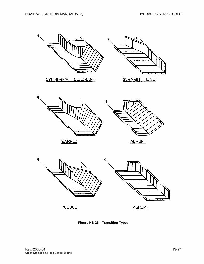
DRAINAGE CRITERIA MANUAL (V. 2) HYDRAULIC STRUCTURES
Figure HS-25—Transition Types
Rev. 2008-04 HS-97 Urban Drainage & Flood Control District
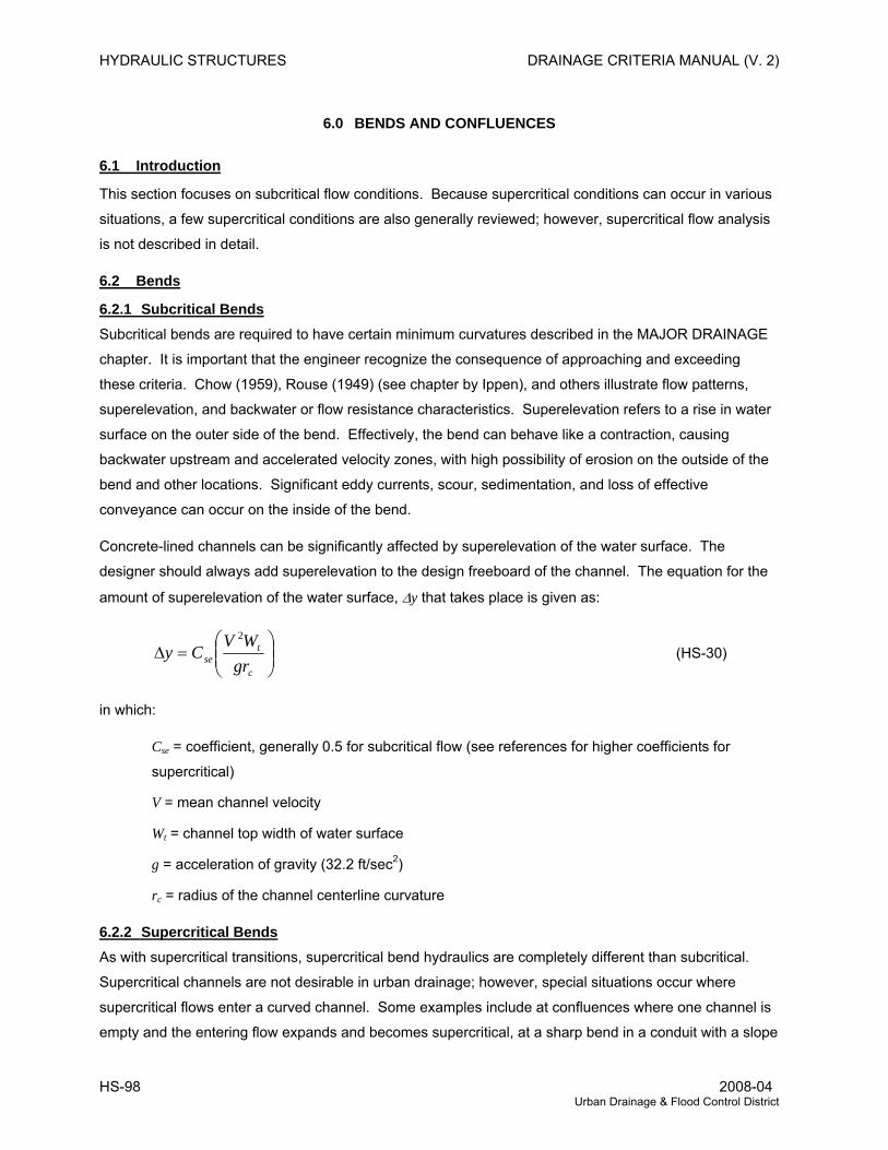
HYDRAULIC STRUCTURES DRAINAGE CRITERIA MANUAL (V. 2)
6.0 BENDS AND CONFLUENCES
6.1 Introduction
This section focuses on subcritical flow conditions. Because supercritical conditions can occur in various
situations, a few supercritical conditions are also generally reviewed; however, supercritical flow analysis
is not described in detail.
6.2 Bends
6.2.1 Subcritical Bends Subcritical bends are required to have certain minimum curvatures described in the MAJOR DRAINAGE
chapter. It is important that the engineer recognize the consequence of approaching and exceeding
these criteria. Chow (1959), Rouse (1949) (see chapter by Ippen), and others illustrate flow patterns,
superelevation, and backwater or flow resistance characteristics. Superelevation refers to a rise in water
surface on the outer side of the bend. Effectively, the bend can behave like a contraction, causing
backwater upstream and accelerated velocity zones, with high possibility of erosion on the outside of the
bend and other locations. Significant eddy currents, scour, sedimentation, and loss of effective
conveyance can occur on the inside of the bend.
Concrete-lined channels can be significantly affected by superelevation of the water surface. The
designer should always add superelevation to the design freeboard of the channel. The equation for the
amount of superelevation of the water surface, Δy that takes place is given as:
⎟⎟⎠
⎞⎜⎜⎝
⎛=Δ
c
tse gr
WVCy
2
(HS-30)
in which:
Cse = coefficient, generally 0.5 for subcritical flow (see references for higher coefficients for
supercritical)
V = mean channel velocity
Wt = channel top width of water surface
g = acceleration of gravity (32.2 ft/sec2)
rc = radius of the channel centerline curvature
6.2.2 Supercritical Bends As with supercritical transitions, supercritical bend hydraulics are completely different than subcritical.
Supercritical channels are not desirable in urban drainage; however, special situations occur where
supercritical flows enter a curved channel. Some examples include at confluences where one channel is
empty and the entering flow expands and becomes supercritical, at a sharp bend in a conduit with a slope
HS-98 2008-04 Urban Drainage & Flood Control District
DRAINAGE CRITERIA MANUAL (V. 2) HYDRAULIC STRUCTURES
that inherently leads to supercritical conditions, or at a channel drop that unavoidably ends up on a curve.
The main phenomenon to be aware of is shock waves, of which there are two types: positive and
negative. On the outside of an angular bend, a positive shock wave will occur that results in a rise in
water surface. The wave is stationary and crosses to the inside of the channel and then can continue to
reflect back and forth. Where the flow passes the inside angular bend, a separation will occur, and a
negative shock wave or drop in water surface will occur. This stationary negative shock wave will cross to
the outside of the channel. Both shock waves will continue to reflect off the walls, resulting in a very
disturbed flow pattern.
A basic control technique is to set up bend geometry to cause the positive shock wave to intersect the
point where the negative wave is propagated. A bend usually requires two deflections on the outside and
one bend on the inside. A beneficial aspect of the shock wave is that it turns the flow in a predictable
pattern; thus, the channel walls have no more force imposed on them than that caused by the increased
(or decreased) depths. This technique is described in Rouse (1949), USACE (1970), and Chow (1959).
Other control techniques include very gradual bends, super elevated floors and control sills, but these
methods are generally less efficient. There is limited data on channels with sloping side banks, but it is
clear there is a great tendency for shock waves to propagate up side slopes and divert flow out of the
channel. Chow (1959) shows several good photographs of these problems. The SCS (1976) presents a
documental report of a curved spillway on a modest flood control storage facility. During an overflow
event, a shock wave pattern was produced that resulted in no flow on one side of a spillway, and great
depths on the opposite.
Another problem observed at bends when channels operate under supercritical conditions is flow jumping
out of the channel at the bend. When this happens, the downstream channel no longer carries the design
flow and major damages to prosperities in line with the flows jumping out of the channel can and have
occurred.
A special problem with long conduits used for flood control, particularly large box culverts, is that they will
have an inherent tendency toward supercritical flow conditions at less than full capacity. When
supercritical flow encounters bends or transitions, standing and reflective waves can occur which hit the
ceiling of the culvert and can cause pressurized conditions or unstable conditions where the flow
fluctuates between supercritical free surface flow and pressurized pipe flow conditions, often exacerbated
by pressure variations in the pipe that can range from less than atmospheric to pressures approaching full
velocity head. It is recommended that there be no bends or very gradual bends in conduits, along with air
venting be provided when supercritical flows are expected in conduits, especially rectangular ones.
Use extreme caution in design anytime supercritical flow may occur and may encounter a bend or a
transition.
Rev. 2008-04 HS-99 Urban Drainage & Flood Control District

HYDRAULIC STRUCTURES DRAINAGE CRITERIA MANUAL (V. 2)
6.3 Confluences
Some of the most difficult problems to deal with are confluences where the difference in flow
characteristics may be great. When the flow enters the combined channel, the flow can diverge and drop
in level if the flow capacity is suddenly increased. This can result in high velocity or unstable supercritical
flow conditions with high erosion potential. When significant sediment flows exist, aggradation can occur
at the confluence, resulting in loss of capacity in one or both upstream channels. The following material
is adapted from Hydraulic Design of Flood Control Channels (USACE 1970).
6.3.1 Subcritical Flow Confluence Design The design of channel junctions is complicated by variables such as the angle of intersection, shape and
width of the channels, flow rates, and type of flow. The design of large complex junctions should be
verified by model tests. The momentum equation design approach has been verified for small angles by
Taylor (1944) and Webber and Greated (1966).
Figure HS-26 illustrates two types of junctions. The following assumptions are made for combining
subcritical flows.
1. The side channel cross section is the same shape as the main channel cross section.
2. The bottom slopes are equal for the main channel and the side channel.
3. Flows are parallel to the channel walls immediately above and below the junction.
4. The depths are equal immediately above the junction in both the side and main channel.
5. The velocity is uniform over the cross sections immediately above and below the junction.
Assumption number 3 implies that hydrostatic pressure distributions can be assumed, and assumption
number 5 suggests that the momentum correction factors are equal to each other at the reference
sections.
The equation governing flow conditions for a vertical walled channel with the main channel width constant
is shown in Figure HS-26(a) and the following equation:
( )2
cos2
21
2
22
1
21
23
3
23 by
gAQ
gAQby
gAQ
++=+θ
(HS-31)
Or, for a vertical walled channel with the main channel width variable, Figure HS-26(b):
( )2
cos2
213
2
22
1
21
233
3
23 yb
gAQ
gAQyb
gAQ
++=+θ
(HS-32)
Or, for a trapezoidal channel with the main channel width constant, Figure HS-26(a):
HS-100 2008-04 Urban Drainage & Flood Control District
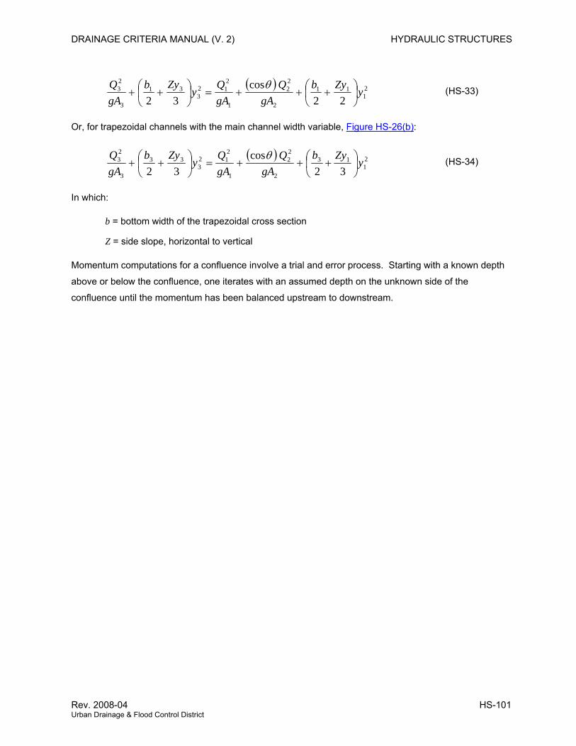
DRAINAGE CRITERIA MANUAL (V. 2) HYDRAULIC STRUCTURES
( ) 21
11
2
22
1
212
331
3
23
22cos
32yZyb
gAQ
gAQy
ZybgAQ
⎟⎠⎞
⎜⎝⎛ +++=⎟
⎠⎞
⎜⎝⎛ ++
θ (HS-33)
Or, for trapezoidal channels with the main channel width variable, Figure HS-26(b):
( ) 21
13
2
22
1
212
333
3
23
32cos
32yZyb
gAQ
gAQy
ZybgAQ
⎟⎠⎞
⎜⎝⎛ +++=⎟
⎠⎞
⎜⎝⎛ ++
θ (HS-34)
In which:
b = bottom width of the trapezoidal cross section
Z = side slope, horizontal to vertical
Momentum computations for a confluence involve a trial and error process. Starting with a known depth
above or below the confluence, one iterates with an assumed depth on the unknown side of the
confluence until the momentum has been balanced upstream to downstream.
Rev. 2008-04 HS-101 Urban Drainage & Flood Control District
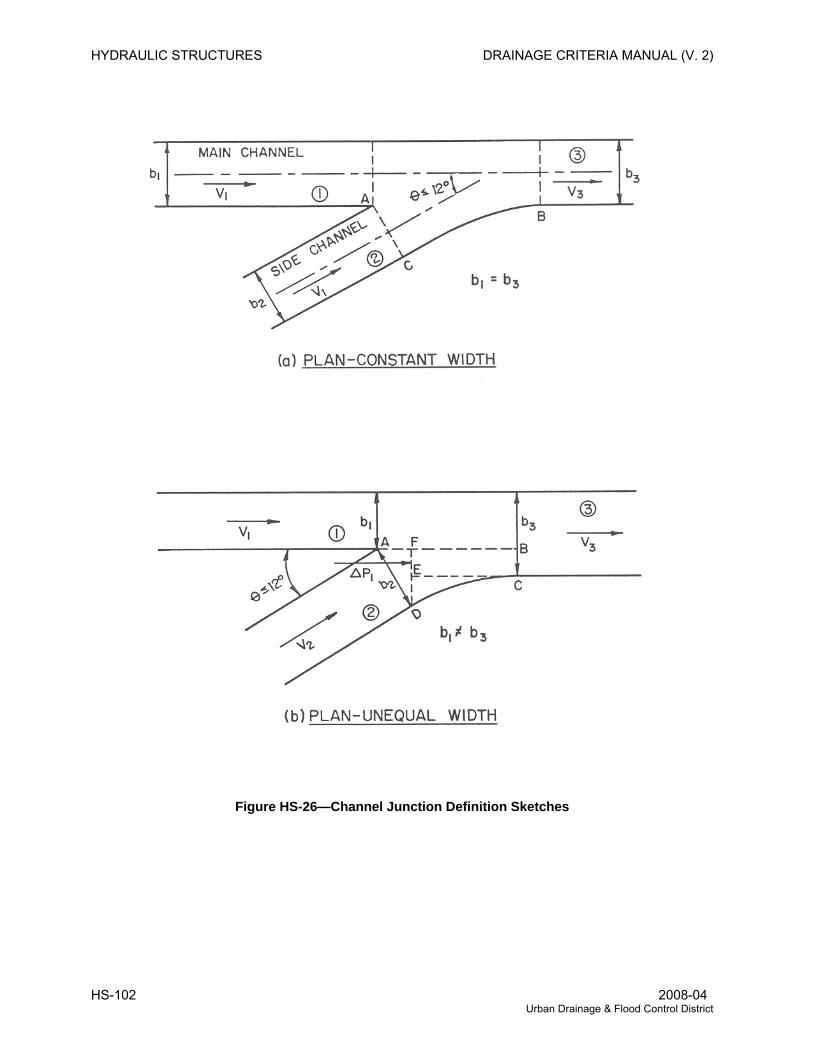
HYDRAULIC STRUCTURES DRAINAGE CRITERIA MANUAL (V. 2)
Figure HS-26—Channel Junction Definition Sketches
HS-102 2008-04 Urban Drainage & Flood Control District
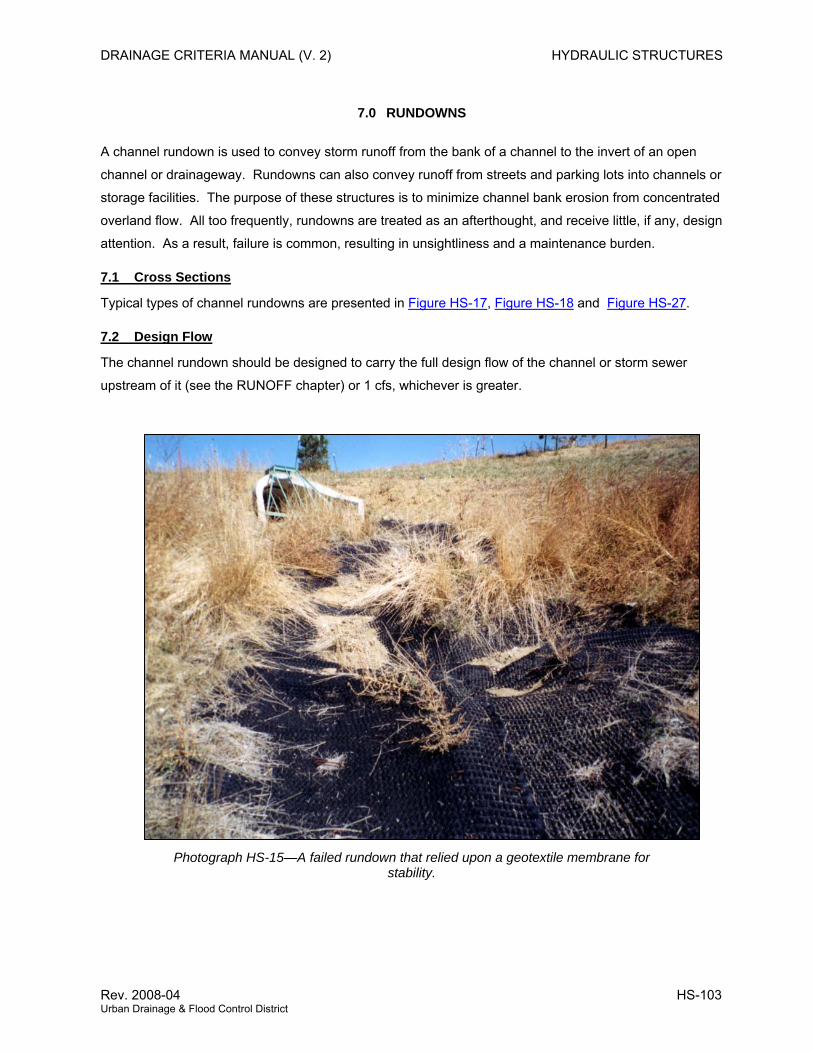
DRAINAGE CRITERIA MANUAL (V. 2) HYDRAULIC STRUCTURES
7.0 RUNDOWNS
A channel rundown is used to convey storm runoff from the bank of a channel to the invert of an open
channel or drainageway. Rundowns can also convey runoff from streets and parking lots into channels or
storage facilities. The purpose of these structures is to minimize channel bank erosion from concentrated
overland flow. All too frequently, rundowns are treated as an afterthought, and receive little, if any, design
attention. As a result, failure is common, resulting in unsightliness and a maintenance burden.
7.1 Cross Sections
Typical types of channel rundowns are presented in Figure HS-17, Figure HS-18 and Figure HS-27.
7.2 Design Flow
The channel rundown should be designed to carry the full design flow of the channel or storm sewer
upstream of it (see the RUNOFF chapter) or 1 cfs, whichever is greater.
Photograph HS-15—A failed rundown that relied upon a geotextile membrane for stability.
Rev. 2008-04 HS-103 Urban Drainage & Flood Control District
HYDRAULIC STRUCTURES DRAINAGE CRITERIA MANUAL (V. 2)
7.3 Flow Depth
The maximum depth at the design flow should be equal to the calculated flow depth using drawdown
calculations for the design flow plus 6 inches of freeboard. Due to the typical profile of a channel
rundown beginning with a flat slope and then dropping steeply into the channel or storage facility, the
design depth of flow should be the computed critical depth for the design flow.
7.4 Outlet Configuration for Trickle Channel
The channel rundown outlet should enter the drainageway at the trickle channel flow line. Erosion
protection of the opposite channel bank should be provided by a layer of buried, grouted, Type B18
boulders. The width of this riprap erosion protection should be at least three times the channel rundown
width or pipe diameter. Riprap protection should extend up the opposite bank to the minor storm flow
depth in the drainageway or 2 feet, whichever is greater. Rundowns discharging into storage facilities
should have comparable scour protection at the outlet, typically in the form of buried, grouted, Type B18
boulders. A forebay upstream of a trickle channel sized in accordance with Volume 3 recommendations
of this Manual can provide this energy dissipation.
7.5 Outlet Configuration for Wetland Channel
For a wetland channel or low-flow channel, the rundown must be carried to the edge of the wetland where
grouted rock is placed to dissipate the kinetic energy so that rundown discharge velocities do not cause
erosion of the wetland. A low tailwater basin is also suitable for this purpose.
7.6 Grouted Boulder Rundowns
Instead of a concrete rundown, a grouted boulder rundown illustrated in Figure HS-18 can be provided.
At a minimum, the width of a grouted boulder rundown should equal the width of the upstream storm
sewer. The rundown depth should start at about ¾ of the height of the upstream pipe at the pipe and
taper down to a depth equal to the calculated drawdown depth of water along the rundown plus 9 inches
of freeboard. To find the depth of flow use Manning’s n from Figure HS-3b. This will require iteration to
find the value n that matches the depth of flow. Use boulders equal to at least 1/2 the height of the pipe
(see boulder classifications in Table MD-8 of the MAJOR DRAINAGE chapter) grouted in accordance with
the recommendations of Section 4.2.1.2 of the MAJOR DRAINAGE chapter.
HS-104 2008-04 Urban Drainage & Flood Control District
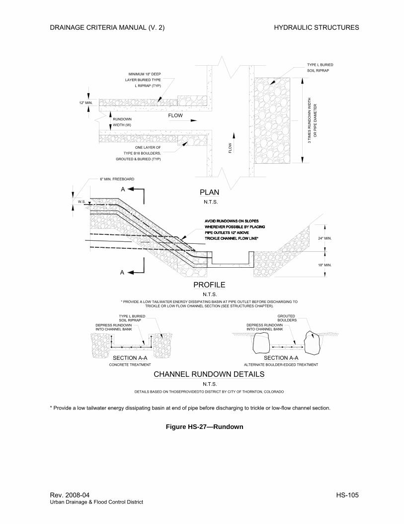
DRAINAGE CRITERIA MANUAL (V. 2) HYDRAULIC STRUCTURES
* Provide a low tailwater energy dissipating basin at end of pipe before discharging to trickle or low-flow channel section.
N.T.S.
A
A PLAN
SECTION A-A
PROFILE
RUNDOWNWIDTH (W)
FLOW
FLO
W
3 TI
ME
S R
UN
DO
WN
WID
THO
R P
I PE
DIA
ME
TER
ONE LAYER OFTYPE B18 BOULDERS,
GROUTED & BURIED (TYP)
DEPRESS RUNDOWNINTO CHANNEL BANK
DETAILS BASED ON THOSEPROVIDEDTO DISTRICT BY CITY OF THORNTON, COLORADO
MINIMUM 18" DEEP
L RIPRAP (TYP)LAYER BURIED TYPE
18" MIN.
24" MIN.
CHANNEL RUNDOWN DETAILS
12" MIN.
SOIL RIPRAP
TRICKLE CHANNEL FLOW LINE*
AVOID RUNDOWNS ON SLOPESWHEREVER POSSIBLE BY PLACING
PIPE OUTLETS 12" ABOVE
TYPE L BURIED
6" MIN. FREEBOARD
W.S.
TYPE L BURIEDSOIL RIPRAP
N.T.S.
N.T.S.
* PROVIDE A LOW TAILWATER ENERGY DISSIPATING BASIN AT PIPE OUTLET BEFORE DISCHARGING TO TRICKLE OR LOW FLOW CHANNEL SECTION (SEE STRUCTURES CHAPTER).
WHEREVER POSSIBLE BY PLACINGAVOID RUNDOWNS ON SLOPES
TRICKLE CHANNEL FLOW LINE*PIPE OUTLETS 12" ABOVEWHEREVER POSSIBLE BY PLACINGAVOID RUNDOWNS ON SLOPES
TRICKLE CHANNEL FLOW LINE*PIPE OUTLETS 12" ABOVEWHEREVER POSSIBLE BY PLACINGAVOID RUNDOWNS ON SLOPES
TRICKLE CHANNEL FLOW LINE*PIPE OUTLETS 12" ABOVE
SECTION A-AALTERNATE BOULDER-EDGED TREATMENTCONCRETE TREATMENT
GROUTEDBOULDERS
DEPRESS RUNDOWNINTO CHANNEL BANK
Figure HS-27—Rundown
Rev. 2008-04 HS-105 Urban Drainage & Flood Control District
HYDRAULIC STRUCTURES DRAINAGE CRITERIA MANUAL (V. 2)
8.0 MAINTENANCE
8.1 General
Maintenance of structures includes removing debris, excessive vegetation and excessive sediment.
Replacing or realigning stones, repairing grout and concrete, and replacing warning signs are also items
of maintenance that cannot be avoided under normal conditions. Refer to the District’s Maintenance
Eligibility Guidelines as contained on the CD version of this Manual for specific guidance on maintenance
provisions for many of the structures addressed in this chapter. See the District’s Web site
(www.udfcd.org) for the latest updates to these guidelines.
8.2 Access
During the design process, attention must be given to providing for adequate maintenance access from
one or both banks in accordance with current District regulations and guidelines.
8.3 Maintenance Optimization
Structures should be designed in accordance with public works policies related to minimizing operation
and maintenance requirements.
HS-106 2008-04 Urban Drainage & Flood Control District
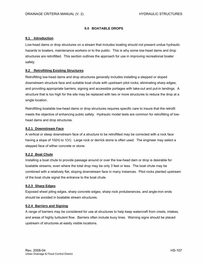
DRAINAGE CRITERIA MANUAL (V. 2) HYDRAULIC STRUCTURES
9.0 BOATABLE DROPS
9.1 Introduction
Low-head dams or drop structures on a stream that includes boating should not present undue hydraulic
hazards to boaters, maintenance workers or to the public. This is why some low-head dams and drop
structures are retrofitted. This section outlines the approach for use in improving recreational boater
safety.
9.2 Retrofitting Existing Structures
Retrofitting low-head dams and drop structures generally includes installing a stepped or sloped
downstream structure face and suitable boat chute with upstream pilot rocks; eliminating sharp edges;
and providing appropriate barriers, signing and accessible portages with take-out and put-in landings. A
structure that is too high for the site may be replaced with two or more structures to reduce the drop at a
single location.
Retrofitting boatable low-head dams or drop structures requires specific care to insure that the retrofit
meets the objective of enhancing public safety. Hydraulic model tests are common for retrofitting of low-
head dams and drop structures.
9.2.1 Downstream Face A vertical or steep downstream face of a structure to be retrofitted may be corrected with a rock face
having a slope of 10(H) to 1(V). Large rock or derrick stone is often used. The engineer may select a
stepped face of either concrete or stone.
9.2.2 Boat Chute Installing a boat chute to provide passage around or over the low-head dam or drop is desirable for
boatable streams, even where the total drop may be only 3 feet or less. The boat chute may be
combined with a relatively flat, sloping downstream face in many instances. Pilot rocks planted upstream
of the boat chute signal the entrance to the boat chute.
9.2.3 Sharp Edges Exposed sheet piling edges, sharp concrete edges, sharp rock protuberances, and angle-iron ends
should be avoided in boatable stream structures.
9.2.4 Barriers and Signing A range of barriers may be considered for use at structures to help keep watercraft from crests, intakes,
and areas of highly turbulent flow. Barriers often include buoy lines. Warning signs should be placed
upstream of structures at easily visible locations.
Rev. 2008-04 HS-107 Urban Drainage & Flood Control District
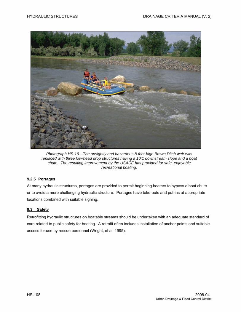
HYDRAULIC STRUCTURES DRAINAGE CRITERIA MANUAL (V. 2)
Photograph HS-16—The unsightly and hazardous 8-foot-high Brown Ditch weir was replaced with three low-head drop structures having a 10:1 downstream slope and a boat
chute. The resulting improvement by the USACE has provided for safe, enjoyable recreational boating.
9.2.5 Portages At many hydraulic structures, portages are provided to permit beginning boaters to bypass a boat chute
or to avoid a more challenging hydraulic structure. Portages have take-outs and put-ins at appropriate
locations combined with suitable signing.
9.3 Safety
Retrofitting hydraulic structures on boatable streams should be undertaken with an adequate standard of
care related to public safety for boating. A retrofit often includes installation of anchor points and suitable
access for use by rescue personnel (Wright, et al. 1995).
HS-108 2008-04 Urban Drainage & Flood Control District
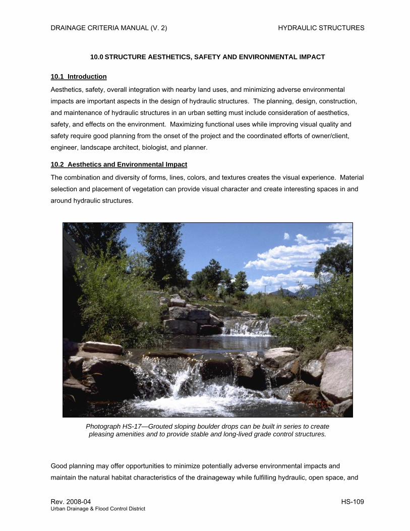
DRAINAGE CRITERIA MANUAL (V. 2) HYDRAULIC STRUCTURES
10.0 STRUCTURE AESTHETICS, SAFETY AND ENVIRONMENTAL IMPACT
10.1 Introduction
Aesthetics, safety, overall integration with nearby land uses, and minimizing adverse environmental
impacts are important aspects in the design of hydraulic structures. The planning, design, construction,
and maintenance of hydraulic structures in an urban setting must include consideration of aesthetics,
safety, and effects on the environment. Maximizing functional uses while improving visual quality and
safety require good planning from the onset of the project and the coordinated efforts of owner/client,
engineer, landscape architect, biologist, and planner.
10.2 Aesthetics and Environmental Impact
The combination and diversity of forms, lines, colors, and textures creates the visual experience. Material
selection and placement of vegetation can provide visual character and create interesting spaces in and
around hydraulic structures.
Photograph HS-17—Grouted sloping boulder drops can be built in series to create pleasing amenities and to provide stable and long-lived grade control structures.
Good planning may offer opportunities to minimize potentially adverse environmental impacts and
maintain the natural habitat characteristics of the drainageway while fulfilling hydraulic, open space, and
Rev. 2008-04 HS-109 Urban Drainage & Flood Control District
HYDRAULIC STRUCTURES DRAINAGE CRITERIA MANUAL (V. 2)
recreation requirements. As discussed in detail in the POLICY, PLANNING, and MAJOR DRAINAGE
chapters, multiple uses of flood control structures, open space, and parks have proven to be an effective
land use combination. Such structures as channels, overflow structures, grade controls, energy
dissipators, maintenance roads, and others can blend in with the park environment.
In natural and urbanized areas, the use of vegetation for bank protection and landscape treatment is
effective. Bioengineering strategies that incorporate vegetation and natural materials can improve habitat
for fish and wildlife, and create a pleasant environment, as discussed in the MAJOR DRAINAGE chapter.
Plant selection and placement around structures and channel features and use of planting that reduces
erosion, dissipates residual energy, and does not create debris or local scour problems are fundamental
to good aesthetics and environmental quality, as well as hydraulic function. Inclusion of high-
maintenance plantings and spaces with planting that are inaccessible or require extensive care are not
advisable, since they may end up poorly maintained, become a nuisance, and be unattractive.
In highly developed streamside areas, concrete plazas and edge treatment can be combined to increase
channel efficiencies while providing reasonable access to the waterway area. Geometric and
architectural forms, hard edges, and formal arrangements of materials are generally associated with
urban settings. However, all of these features require sound engineering and evaluation of the structure
stability and the effects on the hydraulic characteristics of the channel. Such facilities are usually well
received by the public.
A variety of materials and finishes are available for use in hydraulic structures. Concrete color additives,
exposed aggregates and form liners can be used to create visual interest to otherwise stark walls. The
location of expansion and control joints in combination with edges can be used to help create attractive
design detailing of headwalls and abutments.
Natural materials, rock, and vegetation can be used for bank stability and erosion protection while
providing unusual interest, spatial character, and diversity. The placement and type of the rock can
provide poor or pleasing appearance. A stepped boulder arrangement for drops, where there is a larger
top horizontal surface, is usually an appealing placement that also improves hydraulics.
10.3 Safety
Design and construction of urban drainage facilities must account for potential public safety hazards.
When planning and providing for recreation within public parks and open space, safety must always be
considered, and safety for the public and maintenance workers should be incorporated. The design
engineer must consider the variations in hydraulic jumps as they relate to the tailwater elevation as
illustrated in Figure HS-28. Some hydraulic structures and drainage features offer an invitation to play;
therefore, what is constructed should be made safe and attractive. While safety, to a reasonable extent,
becomes the responsibility of the user, appropriate warning signage must be used. In some instances,
HS-110 2008-04 Urban Drainage & Flood Control District
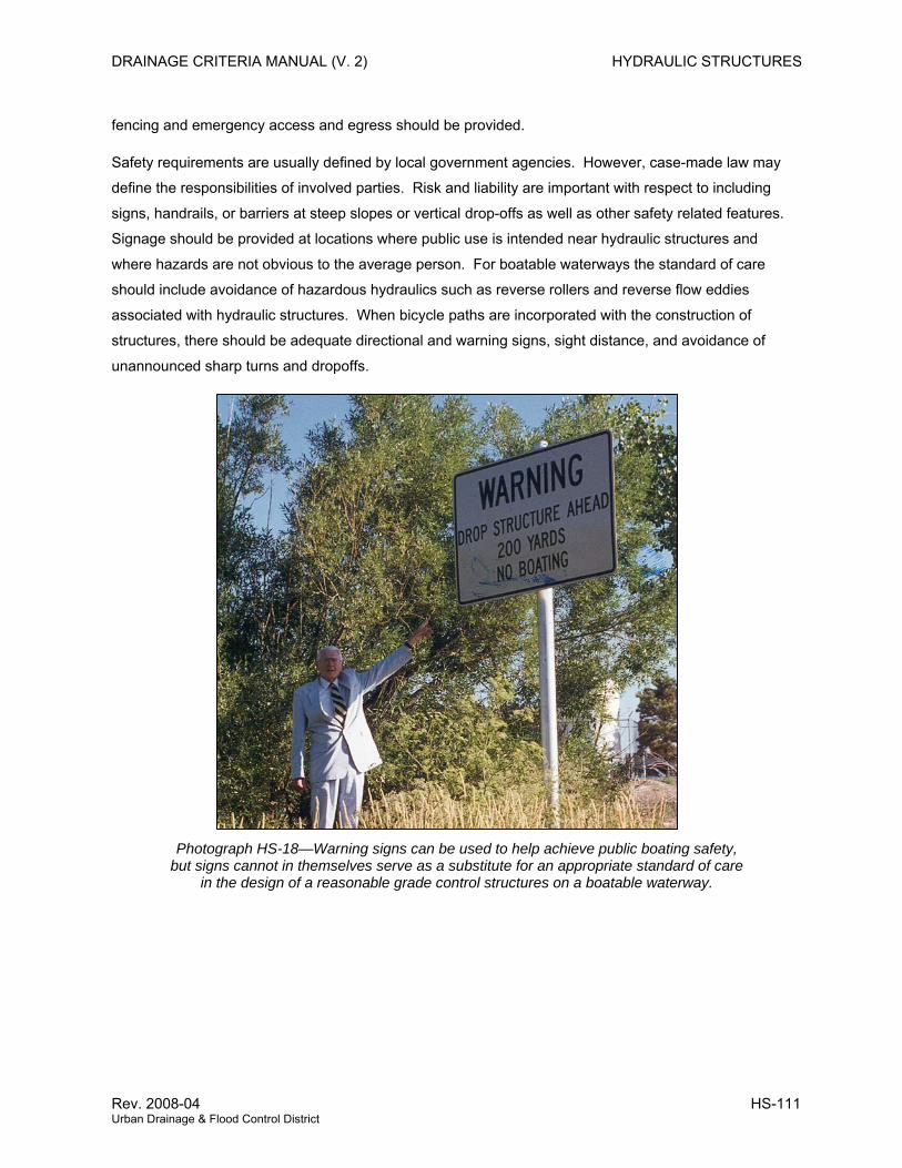
DRAINAGE CRITERIA MANUAL (V. 2) HYDRAULIC STRUCTURES
fencing and emergency access and egress should be provided.
Safety requirements are usually defined by local government agencies. However, case-made law may
define the responsibilities of involved parties. Risk and liability are important with respect to including
signs, handrails, or barriers at steep slopes or vertical drop-offs as well as other safety related features.
Signage should be provided at locations where public use is intended near hydraulic structures and
where hazards are not obvious to the average person. For boatable waterways the standard of care
should include avoidance of hazardous hydraulics such as reverse rollers and reverse flow eddies
associated with hydraulic structures. When bicycle paths are incorporated with the construction of
structures, there should be adequate directional and warning signs, sight distance, and avoidance of
unannounced sharp turns and dropoffs.
Photograph HS-18—Warning signs can be used to help achieve public boating safety, but signs cannot in themselves serve as a substitute for an appropriate standard of care
in the design of a reasonable grade control structures on a boatable waterway.
Rev. 2008-04 HS-111 Urban Drainage & Flood Control District
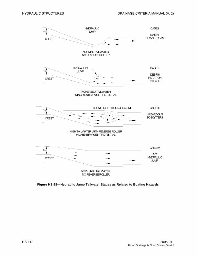
HYDRAULIC STRUCTURES DRAINAGE CRITERIA MANUAL (V. 2)
Figure HS-28—Hydraulic Jump Tailwater Stages as Related to Boating Hazards
HS-112 2008-04 Urban Drainage & Flood Control District
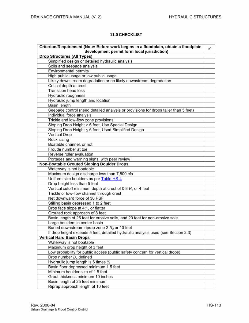
DRAINAGE CRITERIA MANUAL (V. 2) HYDRAULIC STRUCTURES
11.0 CHECKLIST
Criterion/Requirement (Note: Before work begins in a floodplain, obtain a floodplain development permit form local jurisdiction)
Drop Structures (All Types) Simplified design or detailed hydraulic analysis Soils and seepage analysis Environmental permits High public usage or low public usage Likely downstream degradation or no likely downstream degradation Critical depth at crest Transition head loss Hydraulic roughness Hydraulic jump length and location Basin length Seepage control (need detailed analysis or provisions for drops taller than 5 feet) Individual force analysis Trickle and low-flow zone provisions Sloping Drop Height > 6 feet, Use Special Design Sloping Drop Height < 6 feet, Used Simplified Design Vertical Drop Rock sizing Boatable channel, or not Froude number at toe Reverse roller evaluation Portages and warning signs, with peer review Non-Boatable Grouted Sloping Boulder Drops Waterway is not boatable Maximum design discharge less than 7,500 cfs Uniform size boulders as per Table HS-4 Drop height less than 5 feet Vertical cutoff minimum depth at crest of 0.8 Hd or 4 feet Trickle or low-flow channel through crest Net downward force of 30 PSF Stilling basin depressed 1 to 2 feet Drop face slope at 4:1, or flatter Grouted rock approach of 8 feet Basin length of 25 feet for erosive soils, and 20 feet for non-erosive soils Large boulders in center basin Buried downstream riprap zone 2 Hd or 10 feet If drop height exceeds 5 feet, detailed hydraulic analysis used (see Section 2.3) Vertical Hard Basin Drops Waterway is not boatable Maximum drop height of 3 feet Low probability for public access (public safety concern for vertical drops) Drop number Dn defined Hydraulic jump length is 6 times Y2 Basin floor depressed minimum 1.5 feet Minimum boulder size of 1.5 feet Grout thickness minimum 10 inches Basin length of 25 feet minimum Riprap approach length of 10 feet
Rev. 2008-04 HS-113 Urban Drainage & Flood Control District
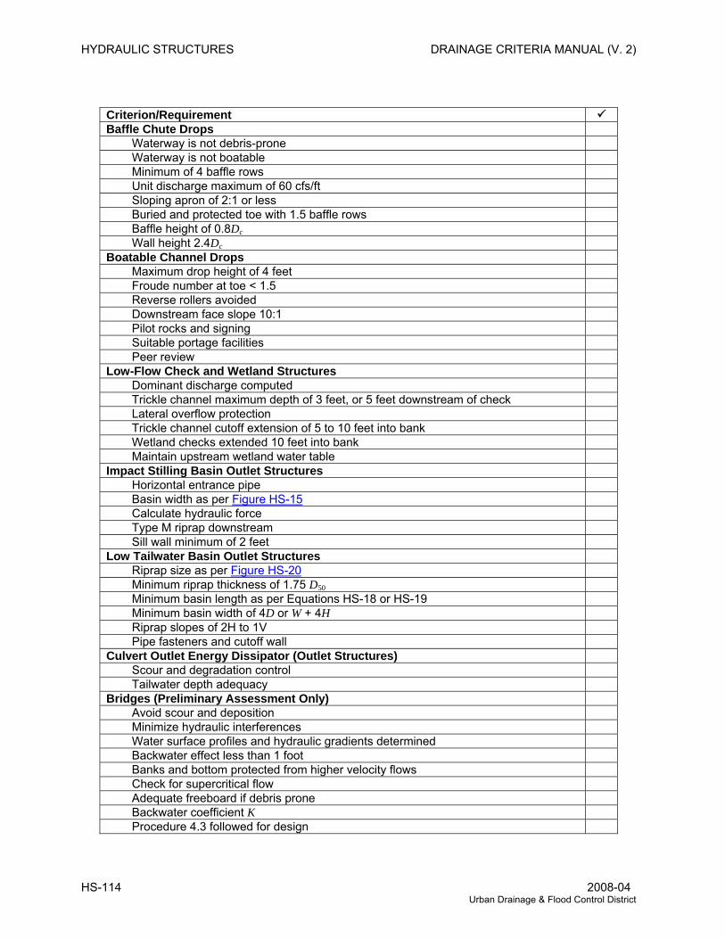
HYDRAULIC STRUCTURES DRAINAGE CRITERIA MANUAL (V. 2)
Criterion/Requirement Baffle Chute Drops Waterway is not debris-prone Waterway is not boatable Minimum of 4 baffle rows Unit discharge maximum of 60 cfs/ft Sloping apron of 2:1 or less Buried and protected toe with 1.5 baffle rows Baffle height of 0.8Dc Wall height 2.4Dc Boatable Channel Drops Maximum drop height of 4 feet Froude number at toe < 1.5 Reverse rollers avoided Downstream face slope 10:1 Pilot rocks and signing Suitable portage facilities Peer review Low-Flow Check and Wetland Structures Dominant discharge computed Trickle channel maximum depth of 3 feet, or 5 feet downstream of check Lateral overflow protection Trickle channel cutoff extension of 5 to 10 feet into bank Wetland checks extended 10 feet into bank Maintain upstream wetland water table Impact Stilling Basin Outlet Structures Horizontal entrance pipe Basin width as per Figure HS-15 Calculate hydraulic force Type M riprap downstream Sill wall minimum of 2 feet Low Tailwater Basin Outlet Structures Riprap size as per Figure HS-20 Minimum riprap thickness of 1.75 D50 Minimum basin length as per Equations HS-18 or HS-19 Minimum basin width of 4D or W + 4H Riprap slopes of 2H to 1V Pipe fasteners and cutoff wall Culvert Outlet Energy Dissipator (Outlet Structures) Scour and degradation control Tailwater depth adequacy Bridges (Preliminary Assessment Only) Avoid scour and deposition Minimize hydraulic interferences Water surface profiles and hydraulic gradients determined Backwater effect less than 1 foot Banks and bottom protected from higher velocity flows Check for supercritical flow Adequate freeboard if debris prone Backwater coefficient K Procedure 4.3 followed for design
HS-114 2008-04 Urban Drainage & Flood Control District
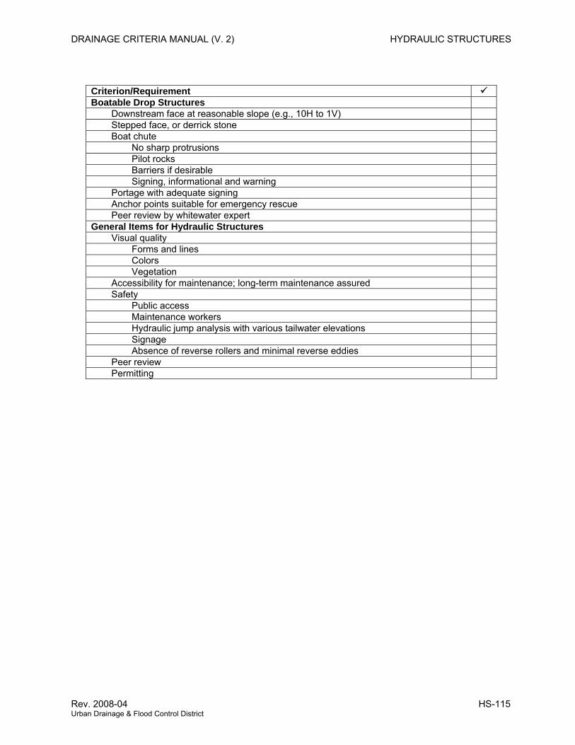
DRAINAGE CRITERIA MANUAL (V. 2) HYDRAULIC STRUCTURES
Criterion/Requirement Boatable Drop Structures Downstream face at reasonable slope (e.g., 10H to 1V) Stepped face, or derrick stone Boat chute No sharp protrusions Pilot rocks Barriers if desirable Signing, informational and warning Portage with adequate signing Anchor points suitable for emergency rescue Peer review by whitewater expert General Items for Hydraulic Structures Visual quality Forms and lines Colors Vegetation Accessibility for maintenance; long-term maintenance assured Safety Public access Maintenance workers Hydraulic jump analysis with various tailwater elevations Signage Absence of reverse rollers and minimal reverse eddies Peer review Permitting
Rev. 2008-04 HS-115 Urban Drainage & Flood Control District
HYDRAULIC STRUCTURES DRAINAGE CRITERIA MANUAL (V. 2)
12.0 REFERENCES
Abt, S.R., J.R. Ruff, R.J. Wittler and D.L. LaGrone. 1987. Gradation and Layer Thickness Effects on
Riprap. In ASCE National Conference on Hydraulic Engineering. New York: ASCE.
———. 1986. Environmental Assessment of Uranium Recovery Activities—Riprap Testing. Phase I.
Oak Ridge, TN: Oak Ridge National Laboratory.
Aisenbrey, A.J., R.B. Hayes, J.H. Warren, D.L. Winsett and R.G. Young. 1978. Design of Small Canal
Structures. Washington, DC: U.S. Department of the Interior, Bureau of Reclamation.
American Association of State Highway and Transportation Officials (AASHTO) Task Force on Hydrology
and Hydraulics, Highway Subcommittee on Design. 1987. Hydraulic Analysis. Location and
Design of Bridges. Washington, DC: AASHTO.
American Society of Civil Engineers and Water Environment Federation (ASCE and WEF). 1992. Design
and Construction of Urban Stormwater Management Systems. American Society of Civil
Engineers Manuals and Reports of Engineering Practice No. 77 and Water Environment
Federation Manual of Practice FD-20. New York: ASCE.
Anderson, AG., A.S. Paintal, and J.T. Davenport. 1968. Tentative Design Procedure for Riprap Lined
Channels. Project Design Report No. 96. Minneapolis, MN: St. Anthony Falls Hydraulic
Laboratory, University of Minnesota.
Anderson, A.G. 1973. Tentative Design Procedure for Riprap Lined Channels—Field Evaluation.
University of Minnesota, St. Anthony Falls Hydraulic Laboratory, Project Report No. 146 Prepared
for Highway Research Board. Washington, DC: National Academy Press.
Barnes, H.H. 1967. Roughness Characteristics of Natural Channels. Water Supply Paper No. 1849.
Washington, DC: U.S. Department of the Interior, Geological Survey.
Bathurst, J.C., R.M. Li, and D.B. Simons. 1979. Hydraulics of Mountain Rivers. Ft. Collins, CO: Civil
Engineering Department, Colorado State University.
Bechdel, L. and S. Ray. 1997. River Rescue, A Manual for Whitewater Safety. Boston, MA:
Appalachian Mountain Club Books.
Behlke, C.E., and H.D. Pritchett. 1966. The Design of Supercritical Flow Channel Junctions. In Highway
Research Record. Washington, DC: National Academy of Sciences.
Beichley, G.L. 1971. Hydraulic Design of Stilling Basin for Pipe or Channel Outlets. Research Report
No. 24. Washington, DC: U.S. Department of the Interior, Bureau of Reclamation.
HS-116 2008-04 Urban Drainage & Flood Control District
DRAINAGE CRITERIA MANUAL (V. 2) HYDRAULIC STRUCTURES
Bethlehem Steel Corporation. 1959. Solving Drainage Problems. Bethlehem, PA: Bethlehem Steel
Corporation.
Blaisdell, F.W. 1949. The SAF Stilling Design. Washington, DC: U.S. Department of Agriculture, Soil
Conservation Service.
Blaisdell, F.W., and C.L. Anderson. 1984. Pipe Spillway Plunge Pool Design Equations. In Water for
Resource Development, D.L. Schreiber ed. New York: ASCE.
Blaisdell, F.W., K.M. Hayward, and C.L. Anderson. 1982. Model-Prototype Scour at Yocona Drop
Structure. In Applying Research to Hydraulic Practice, P.W. Smith, ed., 1-9. New York: ASCE.
Borland-Coogan Associates, Inc. 1980. The Drowning Machine. s.l.: Borland-Coogan Associates.
Bowers, C.E. 1950. Hydraulic Model Studies for Whiting Field Naval Air Station, Part V. In Studies of
Open-Channel Junctions. Project Report No. 24. Minneapolis, MN: St Anthony Falls Hydraulic
Laboratory, University of Minnesota.
Bowers, C.E. and J.W. Toso. 1988. Karnafuli Project, Model Studies of Spillway Damage. Journal of
Hydraulic Engineering 114(5)469-483.
Canada Department of Agriculture. 1951. Report on Steel Sheet Piling Studies. Saskatoon SK: Soil
Mechanics and Materials Division, Canada Department of Agriculture.
Cedergren, H.R. 1967. Seepage Drainage and Flow Nets. New York: John Wiley and Sons.
Chee, S.P. 1983. Riverbed Degradation Due to Plunging Streams. In Symposium of Erosion and
Sedimentation, Ruh-Ming Li, and Peter F. Lagasse, eds. Ft. Collins, CO: Simons, Li and Assoc.
Chen, Y.H. 1985. Embankment Overtopping Tests to Evaluate Damage. In Hydraulics and Hydrology in
the Small Computer Age, Volume 2, W.R. Waldrop, ed. Ft. Collins, CO: Simons, Li and
Associates Inc.
Chow, V.T. 1959. Open-Channel Hydraulics. New York: McGraw-Hill Book Company.
Corry, M.L., P.L. Thompson, F.J. Watts, J.S. Jones, and D.L. Richards. 1975. The Hydraulic Design of
Energy Dissipators for Culverts and Channels. Hydraulic Engineering Circular No. 14.
Washington, DC: Federal Highway Administration.
Cotton, G.K. 1995. Hazard Rating for Low Drops. In Water Resources Engineering, W.H. Espey, Jr. and
P.G. Combs eds., 1111-1115. New York: ASCE.
D’Appalonia, D.J. 1980. Soil Bentonite Slurry Trench Cutoffs. Journal of the Geotechnical Engineering
Division 106(4)395-417.
Rev. 2008-04 HS-117 Urban Drainage & Flood Control District
HYDRAULIC STRUCTURES DRAINAGE CRITERIA MANUAL (V. 2)
Davis, D.W. and M.W. Burnham. 1987. Accuracy of Computed Water Surface Profiles. In Hydraulic
Engineering—1987, R.M. Ragean, ed. 818-823. New York: ASCE.
Donald H. Godi and Associates, Inc. 1984. Guidelines for Development and Maintenance of Natural
Vegetation. Denver, CO: Urban Drainage and Flood Control District.
Forster, J.W. and R.A. Skrindge. 1950. Control of the Hydraulic Jump by Sills. American Society of Civil
Engineers Transactions 115, 973-987.
Henderson, R.M. 1966. Open Channel Flow. New York: Macmillan Company.
Hsu, En-Yun. 1950. Discussion on Control of the Hydraulic Jump by Sills. American Society of Civil
Engineers Transactions 115, 988-991.
Hughes, W.C. 1976. Rock and Riprap Design Manual for Channel Erosion Protection. Boulder, CO:
University of Colorado.
Ippen, A.T. 1951. Mechanics of Supercritical Flows. In High Velocity Flow Open Channels. American
Society of Civil Engineers Transactions 116, 268-295.
Isbash, S.V. 1936. Construction of Dams by Depositing Rock in Running Water. Transactions, Second
Congress on Large Dams. Washington DC: s.n.
Jansen, R.B. 1980. Dams and Public Safety. Washington, DC: U.S. Department of the Interior, Water
and Power Resources Service.
Kindsvatter, C.E., R.W. Carter, and H.J. Tracy. 1953. Computation of Peak Discharge at Contractions.
US Geological Survey Circular 284. Washington, DC: U.S. Geological Survey.
Knapp, R.T. 1951. Design of Channel Curves for Supercritical Flow. In High Veolocity Flow Open
Channels. American Society of Civil Engineers Transactions 116, 296-325.
Lane, E.W. 1935. Security from Under Seepage Masonry Dams on Earth Foundations. American
Society of Civil Engineers Transactions 100, 1235-1272.
Lane, K.S. and P.E. Wolt. 1961. Performance of Sheet Piling and Blankets for Sealing Missouri River
Reservoirs. In Proceedings, Seventh Congress on Large Dams, 255-279. s.l.: s.n.
Lederle Consulting Engineers. 1985. West Harvard Gulch Rehabilitative Improvements, Engineering
Report on Drop Structure Alternatives. Denver, CO: Urban Drainage and Flood Control District.
Leutheusser. H. and W. Birk. 1991. Drownproofing of Low Overflow Structures. J. Hydraulics Division.
117(HY2)205-213.
HS-118 2008-04 Urban Drainage & Flood Control District
DRAINAGE CRITERIA MANUAL (V. 2) HYDRAULIC STRUCTURES
Li Simons and Associates. 1981. Design Guidelines and Criteria for Channels and Hydraulic Structures
on Sandy Soils. Denver, CO: Urban Drainage and Flood Control District.
———. 1982. Engineering Analysis of Fluvial Systems. Chelsea, MI: Book Crafters.
———. 1982. Surface Mining Water Diversion Design Manual. Washington, DC: Office of Surface
Mining.
———. 1985. Design Manual for Engineering Analysis of Fluvial Systems. Phoenix, AZ: Arizona
Department of Water Resources.
———. 1986. Project Report Hydraulic Model Study of Local Scour Downstream of Rigid Grade Control
Structures. Tucson, AZ: Pima County Department of Transportation and Flood Control District.
———. 1989. Sizing Riprap for the Protection of Approach Embankments and Spur Pikes—Limiting the
Depth of Scour at Bridge Piers and Abutments. Phoenix, AZ: Arizona Department of
Transportation.
Linder, W.M. 1963. Stabilization of Streambeds with Sheet Piling and Rock Sills. In Proceedings of the
Federal Inter-Agency Sedimentation Conference. Washington, DC: U.S. Department of
Agriculture.
Little, W.C. and J.B. Murphey. 1982. Model Study of Low Drop Grade Control Structures. Journal of
Hydraulics Division 108(HY10).
Little, W.C. and R.C. Daniel. 1981. Design and Construction of Low Drop Structures. In Applying
Research To Hydraulic Practice, P.E. Smith, ed., 21-31. New York: ASCE.
Maynord, S.T. 1978. Practical Riprap Design. Miscellaneous Paper H-78-7. Washington, DC: U.S.
Army, Corps of Engineers.
Maynord, T. and J.F. Ruff. 1987. Riprap Stability on Channel Side Slopes. In ASCE National
Conference on Hydraulic Engineering. New York: ASCE.
McDonald, M.G. and A.W. Harbaugh. 1989. A Modular Three-Dimensional Finite Difference
Groundwater Flow Model. Open File Report 83-875. Denver, CO: U.S. Geological Survey.
McLaughlin Water Engineers, Ltd. (MWE). 1986. Evaluation of and Recommendations for Drop
Structures in the Denver Metropolitan Area. Denver, CO: Urban Drainage and Flood Control
District.
Miller, S.P., Hon-Yim Ko, and J. Dunn. 1985. Embankment Overtopping. In Hydraulics and Hydrology in
the Small Computer Age, Volume 2, W.R. Waldrop, ed. Ft. Collins, CO: Simons, Li and
Associates Inc.
Rev. 2008-04 HS-119 Urban Drainage & Flood Control District
HYDRAULIC STRUCTURES DRAINAGE CRITERIA MANUAL (V. 2)
Millet, R.A. and J. Yves-Perez. 1981. Current USA Practice: Slurry Wall Specification. Journal of the
Geotechnical Engineering Division 107, 1041-1055.
Morgenstern, N. and I. Amir-Tahmasseb. 1985. The Stability of a Slurry Trench in Cohesionless Soils.
Geotechnique 15, 387-395, 1965.
Muller Engineering Co. 1980. Drop Structure Procedure. Denver, CO: Urban Drainage and Flood
Control District.
Mussetter, R.A. 1983. Equilibrium Slopes Above Channel Control Structures. In the Symposium on
Erosion and Sedimentation, Ruh-Ming Li and P.F. Lagasse, eds. Ft. Collins, CO: Li Simons and
Associates, Inc.
Myers, C.T. 1982. Rock Riprap Gradient Control Structures. In Applying Research to Hydraulic Practice,
P.E. Smith, ed., 10-20. New York: ASCE.
Neuman, S.P. and P.A. Witherspoon. 1970. Finite Element Method of Analyzing Steady Seepage with a
Free Surface. Water Resources Research 6(3)889-897.
Olivier, H. 1967. Through and Overflow Rockfill Dams—New Design Techniques. Journal of the Institute
of Civil Engineering, Paper No. 7012.
Pemberton, E.L. and J.M. Lara. 1984. Computing Degradation and Local Scour. Denver, CO: U.S.
Bureau of Reclamation.
Peterka, A.J. 1984. Hydraulic Design of Stilling Basins and Energy Dissipators. Engineering Monograph
No. 25. Washington, DC: U.S. Bureau of Reclamation.
Portland Cement Association. 1964. Handbook of Concrete Culvert Pipe Hydraulics. Chicago, IL:
Portland Cement Association.
Posey, C. J. 1955. Flood-Erosion Protection for Highway Fills, with discussion by Messrs. Gerald H.
Matthes, Emory W. Lane, Carl F. Izzard, Joseph N. Bradley, Carl E. Kindsvater, and Parley R.
Nutey, and Chesley A. Posey. American Society of Civil Engineers Transactions.
Powledge, G.R. and R.A. Dodge. 1985. Overtopping of Small Dams—An Alternative for Dam Safety. In
Hydraulics and Hydrology in the Small Computer Age, Volume 2, W.R. Waldrop, ed. Ft. Collins,
CO: Simons, Li and Associates Inc.
Reese, A.J. 1984. Riprap Sizing—Four Methods. J. Water for Res. Development. New York: ASCE.
Reese, A.J. 1986. Nomographic Riprap Design. Vicksburg, MS: Hydraulics Laboratory, U.S. Army
Corps of Engineers.
HS-120 2008-04 Urban Drainage & Flood Control District
DRAINAGE CRITERIA MANUAL (V. 2) HYDRAULIC STRUCTURES
Reeves, G.N. 1985. Planned Overtopping of Embankments Using Roller Compacted Concrete. In
Hydraulics and Hydrology in the Small Computer Age, Volume 2, W.R. Waldrop, ed. Ft. Collins,
CO: Simons, Li and Associates Inc.
Rhone, T.J. 1977. Baffled Apron as Spillway Energy Dissipator. Journal of the Hydraulics Division
103(12)1391-1401.
Richardson, E.V. 1974. Highways in the River Environment. Washington, DC: U. S. Department of
Transportation, Federal Highway Administration.
———. 1988. Highways in the River Environment. Washington, DC: U. S. Department of
Transportation, Federal Highway Administration.
Rouse, H. 1949. Engineering Hydraulics. Proceedings of the Fourth Hydraulics Conference, Iowa
Institute of Hydraulic Research. New York: John Wiley and Sons, Inc.
Rushton, K.R., and S.C. Redshaw. 1979. Seepage and Groundwater Flow Numerical Analysis by
Analog and Digital Methods. New York: John Wiley and Sons, Inc.
Sabol, G.V, and R.J. Martinek. 1982. Energy Grade/Grade Control Structures for Steep Channels,
Phase ll. Albuquerque, NM: Albuquerque Metropolitan Arroyo Flood Control Authority and City
of Albuquerque.
Samad, M.A. 1978. Analysis of Riprap for Channel Stabilization. Ph.D. Dissertation, Department of Civil
Engineering, Colorado State University.
Samad, M.A., J.P. Pflaum, W.C. Taggart, and R.E. McLaughlin. 1986. Modeling of the Undular Jump for
White River Bypass. In Water Forum ‘86: World Water Issues in Evolution, Volume 1, M.
Karamoutz, G.R. Baumli and W.J. Brich, eds.
Sandover, J.A. and P. Holmes. 1962. Hydraulic Jump in Trapezoidal Channels. Water Power. s.l.: s.n.
Shen, H.W., ed. 1971. River Mechanics, Vol. I and II. Ft. Collins, CO: Colorado State University.
Shields, F.D. Jr. 1982. Environmental Features for Flood Control Channels. Water Res. Bulletin 18(5).
Simons, D.B. 1983. Symposium on Erosion and Sedimentation. Ft. Collins, CO: Simons, Li and
Associates Inc.
Simons, D.B. and F. Sentark. 1977. Sediment Transport Technology. Ft. Collins, CO: Water Res.
Publications.
Smith, C.D. and D.K. Strung. 1967. Scour in Stone Bends. In the Twelfth Congress of the International
Association for Hydraulic Research, CSU, Fort Coffins, Colorado.
Rev. 2008-04 HS-121 Urban Drainage & Flood Control District
HYDRAULIC STRUCTURES DRAINAGE CRITERIA MANUAL (V. 2)
Smith, C.D. and D.G. Murray. 1965. Cobble Lined Drop Structures. Canadian Journal of Civil
Engineering 2(4).
Stevens, M.A. 1976. Hydraulic Design Criteria for Riprapped Chutes and Vertical Drop Structures,
Report prepared for the Urban Drainage and Flood Control District, Denver, Colorado.
———. 1981. Hydraulic Design Criteria for Riprapped Chutes and Vertical Drop Structures. Denver,
CO: Urban Drainage and Flood Control District.
———. 1983. Monitor Report Bear Canyon Creek. Denver, CO: Urban Drainage and Flood Control
District.
———. 1989. Anderson’s Method of Design Notes, August 1982. Provided by Urban Drainage and
Flood Control District, Denver, Colorado.
Stevens, M.A., D.B. Simons, and G.L. Lewis. 1976. Safety Factors for Riprap Protection. Journal of
Hydraulics Division 102(HY5)637-655.
Stevens, M.A. and B.R. Urbonas. 1996. Design of Low Tailwater Riprap Basins for Storm Sewer Pipe
Outlets. Flood Hazard News 26(1)11-14.
Taggart, W.C. 1984. Modifications of Dams for Recreational Boating. Water for Resource Development,
781-785. New York: American Society of Civil Engineers.
Taggart, W.C., C.A. Yermoli, S. Montes, and A.T. Ippen. 1972. Effects of Sediment Size and Gradation
on Concentration Profiles for Turbulent Flow. Cambridge, MA: Department of Civil Engineering,
Massachusetts Institute of Technology.
Taylor, D.W. 1967. Fundamentals of Soil Mechanics. New York: John Wiley and Sons.
Taylor, E.H. 1944. Flow Characteristics at Rectangular Open Channel Junctions. American Society of
Civil Engineers Transactions, 109, Paper No. 2223.
Terzaghi, K. and R.B. Peck. 1948. Soil Mechanics in Engineering Practice. New York: John Wiley and
Sons, Inc.
Toso, J.W. 1986. The Magnitude and Extent of Extreme Pressure Fluctuations in the Hydraulic Jump.
Ph.D. Thesis, University of Minnesota.
Toso, J.W. and C.E. Bowers. 1988. Extreme Pressures in Hydraulic-Jump Stilling Basins. Journal
Hydraulic Engineering 114(HY8).
HS-122 2008-04 Urban Drainage & Flood Control District
DRAINAGE CRITERIA MANUAL (V. 2) HYDRAULIC STRUCTURES
U.S. Army Corp of Engineers (USACE). 1952. Hydrologic and Hydraulic Analysis, Computation of
Backwater Curves in River Channels. Engineering Manual. Washington, DC: Department of the
Army.
———. 1947. Hydraulic Model Study—Los Angeles River Channel Improvements. Washington, DC:
Department of the Army.
———. 1964. Stability of Riprap and Discharge Characteristics, Overflow Embankments, Arkansas
River, Arkansas. Technical Report No. 2-650. Vicksburg, MS: U.S. Army Engineer Waterways
Experiment Station.
———. 1980. Hydraulic Design of Reservoir Outlet Works. EM 1110-2-1602. Washington, DC:
Department of the Army.
———. 1982. HEC-2 Water Surface Profile Users Manual. Davis, CA: Hydrologic Engineering Center.
———. 1984. Drainage and Erosion Control Mobilization Construction. EM 1110-3-136. Washington,
DC: Department of the Army.
———. 1985. Summary Report Model tests of Little Falls Dam Potomac River, Maryland. Washington,
DC: Army Corps of Engineers.
———. 1994. Hydraulic Design of Flood Control Channels. EM 1110-2-1601. Washington, DC:
Department of the Army.
U.S. Bureau of Public Roads. 1967. Use of Riprap for Bank Protection. Hydraulic Engineering Circular,
No. 11. Washington, DC: Department of Commerce.
U.S. Bureau of Reclamation (USBR). 1958. Guide for Computing Water Surface Profiles. Washington,
DC: U.S. Department of the Interior, Bureau of Reclamation.
———. 1987. Design of Small Dams. Denver, CO: Bureau of Reclamation.
U.S. Federal Highway Administration (FHWA). 1960. Hydraulics of Bridge Waterways. Hydraulic Design
Series No. 1. Washington, DC: FHWA.
———. 1978. Hydraulics of Bridge Waterways. Hydraulic Design Series No. 1. Washington, DC:
Department of Transportation.
———. 1988. Design of Roadside Channels with Flexible Linings. Hydraulic Engineering Circular No.
15. Washington, DC: Department of Transportation.
———. 2000. Hydraulic Design of Energy Dissipators for Culverts and Channels. Hydraulic Engineering
Circular 14. Washington, DC: U.S. Department of Transportation, FHWA.
Rev. 2008-04 HS-123 Urban Drainage & Flood Control District
HYDRAULIC STRUCTURES DRAINAGE CRITERIA MANUAL (V. 2)
HS-124 2008-04 Urban Drainage & Flood Control District
U.S. Soil Conservation Service (SCS). 1952. Drop Spillways. SCS Engineering Handbook, Section 11.
Washington, DC: U.S. Department of Agriculture.
———. 1976. Chute Spillways. SCS Engineering Handbook, Section 14. Washington, DC: U.S.
Department of Agriculture.
———. 1976. Hydraulic Design of Riprap Gradient Control Structures. Technical Release No. 59.
Washington, DC: U.S. Department of Agriculture.
———. 1977. Design of Open Channels. Technical Release No. 25. Washington, DC: U.S.
Department of Agriculture.
Urbonas, B.R. 1968. Forces on a Bed Particle in a Dumped Rock Stilling Basin. M.S.C.E. Thesis.
———. 1986. Design of Channels with Wetland Bottoms. Supplement to Flood Hazard News.
Walbridge, C. and J. Tinsley. 1996. The American Canoe Association's River Safety Anthology.
Birmingham, AL: Menasha Ridge Press.
Wang, S. and H.W. Shen. 1985. Incipient Sediment Motion and Riprap Design. Journal of Hydraulic
Engineering 111(HY3)520-538.
Webber, N.B. and C.A. Greated. 1966. An Investigation of Flow Behaviors at the Junction of
Rectangular Channels. Proceedings of the Institution of Civil Engineers 34, Paper No. 6901
Wheat, D. 1989. Floaters Guide to Colorado. Helena, MT: Falcon Press Publishing.
Wittler, R.J. and S.R. Abt. 1988. Riprap Design by Modified Safety Factor Method. In ASCE National
Conference on Hydraulic Engineering. New York: ASCE.
Wright, K.R. 1967. Harvard Gulch Flood Control Project. Journal of the Irrigation and Drainage Division
93(1)15-32.
Wright, K.R., J.M. Kelly, R. J. Houghtalen, and M.R. Bonner. 1995. Emergency Rescues at Low-Head
Dams. Presented at the Association of State Dam Safety Officials Annual Conference in Atlanta.
Wright, K. R. J.M. Kelly and W.S. Allender. 1995. Low-Head Dams Hydraulic Turbulence Hazards.
Presented at the American Society of Civil Engineers Conference on Hydraulic Engineering and the
Symposium on Fundamental and Advancement in Hydraulic Measurements.
Yarnell, D.L. 1934. Bridge Piers as Channel Obstruction. Technical Bulletin No. 442. Washington, DC:
U.S. Soil Conservation Service.