Embed Size (px)
Citation preview

i
Dragon - A400 Operator's Manual
Available in 12 foot or 24 foot models.
Bend-Tech Dragon Support Team
Bend-Tech LLC.
Phone: 1-651-257-8715
Address: 729 Prospect Ave. Osceola, WI, 54020
E-Mail: [email protected]
Website: http://www.bendtechdragon.com

ii
Table Of Contents: Pg. #Introduction and Warranty 1
• Included in this Manual 1
Safety Procedures 2-5
• Personal Protection Equipment (PPE) 2-3
• Pinch Points 3
• Emergency Stop Buttons 4
• General Safety Guidelines 4-5
Machine Capacities 6
Cutting Speed Recommendations 6
• Torch Manual Charts 6-7
• High Speed Vs Low Speed Dross 7
• Consumable Life 7
Cut Charts 8-11
Machine Components 12
Machine Uncrating and Installation 13-14
• Safety And Inspection 13
• Heavy Lifting 13
• Placement in the Shop 13
• Leveling and Anchoring 14
• Ventilation 14
• Humidity and Temperature 14
• Air Requirements 14
Wiring Diagrams and Paths 15-17
• Machine Control Box 15
• Torch Cable Plug 16
• Ground Wiring Path 17
• Air Hose Connections 18
General Machine Operations 19-25

iii
Table Of Contents: Pg. #• Powering On/Powering Off Sequence 19
• Homing the Machine: When? 19
• Using the Machine Controller 20-23
• Library Setup 20-24
• Gate Operations 25
FAQ 26-27
DRAGON Preventative Maintenance Guide 28-30
Thank you and Contact Information 31
1
Introduction:• Bend-Tech LLC. greatly appreciates your new purchase of the Dragon – A400 12' or
24' machine. We stand behind our promise to you in offering our best support in helping you along with getting to know your machine and producing quality parts efficiently and in a timely manner.
• With that in mind, there are certain procedures that we must first set in place in order toget your machine up and running smoothly., so we appreciate your patience during thisperiod. We've taken measures at our shop location to ensure that your machine is capable of operations at your shop and have calibrated it as much as possible to provide you a seamless setup experience.
Included in this manual:• Safety Procedures• Installation Information• Diagram of Machine Components• Machine Dimensions and Capacities• Wiring Diagrams and Paths• Setup and Operating Procedures• Scheduled Maintenance Procedures• Technical Support Information
Warranty:----------------------------------------------------------------------------------------------------------------------------
• Your Dragon machine has a 6 month electronics and hardware limited warranty. Defective or faulty parts identified on your machine within this time period after purchase will be replaced at no charge and shipped to your location.
• After the 6 month warranty period, replacement parts can be purchased through Bend-Tech LLC. and shipped to your location at your discretion.
----------------------------------------------------------------------------------------------------------------------------• Your Dragon software is always improving to ensure the best capabilities for
your company and others. Your maintenance plan for software updates and service is good for 2 years from the Dragon purchase date.
• After this 2 years, an annual software maintenance plan is available to purchase.This will ensure consistent updates to your software product and keep you in the newest capabilities possible. Your Bend-Tech LLC. sales personnel will contact you 1 month to 2 weeks before your maintenance plan expires to ask if you'd like to re-apply for an annual subscription.
• YOUR WARRANTY MAY BECOME VOID OR LIMITED IN THE EVENT THAT YOU MAKE SIGNIFICANT HARDWARE CHANGES TO THE MACHINE.
2
Safety Procedures:
IMPORTANT: PLEASE READ THIS OPERATOR'S MANUAL IN ITS ENTIRETY TO ENSURE YOUR SAFE AND EFFICIENT OPERATION OFYOUR DRAGON A400 MACHINE.
Personal Protective Equipment (PPE):• Metal working can be dangerous if safe and proper operating procedures are not
followed strictly. As with all machinery, there are certain hazards involved with the operation of the product. Using the machine with respect and caution will considerably lessen the possibility of personal injury. However, if normal safety precautions are overlooked or ignored, personal injury to the operator may result.
• Safety equipment such as welder's masks, dust masks, heat resistant gloves, steeltoe boots and hearing protection can reduce your potential for injury. But even the best guard won’t make up for poor judgment, carelessness or inattention. ALWAYS use common sense and exercise caution in the workshop. If a procedure feels dangerous, don’t try it. REMEMBER: Your personal safety is your responsibility.
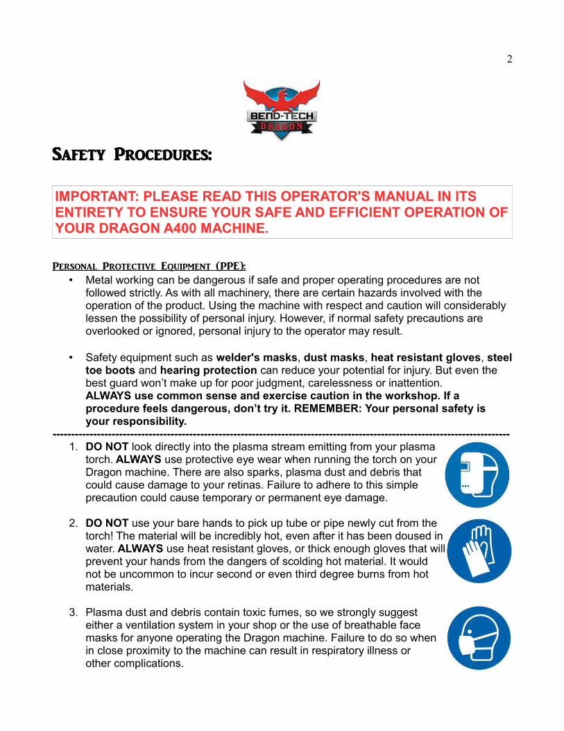
----------------------------------------------------------------------------------------------------------------------------1. DO NOT look directly into the plasma stream emitting from your plasma
torch. ALWAYS use protective eye wear when running the torch on yourDragon machine. There are also sparks, plasma dust and debris thatcould cause damage to your retinas. Failure to adhere to this simpleprecaution could cause temporary or permanent eye damage.
2. DO NOT use your bare hands to pick up tube or pipe newly cut from thetorch! The material will be incredibly hot, even after it has been doused inwater. ALWAYS use heat resistant gloves, or thick enough gloves that willprevent your hands from the dangers of scolding hot material. It wouldnot be uncommon to incur second or even third degree burns from hotmaterials.
3. Plasma dust and debris contain toxic fumes, so we strongly suggesteither a ventilation system in your shop or the use of breathable facemasks for anyone operating the Dragon machine. Failure to do so whenin close proximity to the machine can result in respiratory illness orother complications.
3
4. Hearing protection is recommended around loud machinery. Althoughthis machine isn't particularly noisy, ear protection may be necessary forsome operators with pre-existing hearing problems.
5. ALWAYS wear protective footwear while loading and unloading materialsinto the Dragon machine. We recommend steel toe boots to minimize thechance of personal injury or dismemberment.
KEEP YOUR HANDS AND OTHER APPENDAGES AWAY FROM THE PLASMA TORCH WHILE THE MACHINE IS POWERED ON. PLASMA EMITTING ONTO THE SKIN CAN CAUSE SERIOUS INJURY, DISMEMBERMENT OR EVEN DEATH.
----------------------------------------------------------------------------------------------------------------------------Pinch Points:
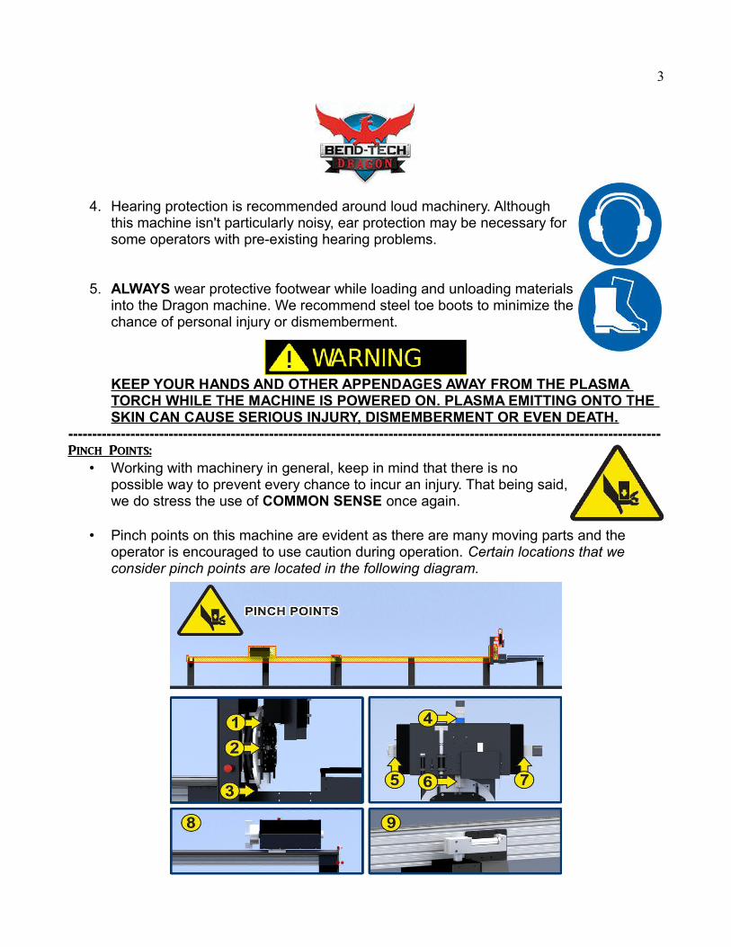
• Working with machinery in general, keep in mind that there is nopossible way to prevent every chance to incur an injury. That being said,we do stress the use of COMMON SENSE once again.
• Pinch points on this machine are evident as there are many moving parts and the operator is encouraged to use caution during operation. Certain locations that we consider pinch points are located in the following diagram.
4
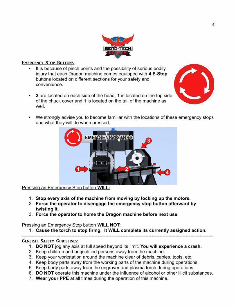
Emergency Stop Buttons:• It is because of pinch points and the possibility of serious bodily
injury that each Dragon machine comes equipped with 4 E-Stop buttons located on different sections for your safety andconvenience.
• 2 are located on each side of the head, 1 is located on the top sideof the chuck cover and 1 is located on the tail of the machine aswell.
• We strongly advise you to become familiar with the locations of these emergency stopsand what they will do when pressed.
Pressing an Emergency Stop button WILL:
1. Stop every axis of the machine from moving by locking up the motors. 2. Force the operator to disengage the emergency stop button afterward by
twisting it.3. Force the operator to home the Dragon machine before next use.
Pressing an Emergency Stop button WILL NOT:1. Cause the torch to stop firing. It WILL complete its currently assigned action.
----------------------------------------------------------------------------------------------------------------------------General Safety Guidelines:
1. DO NOT jog any axis at full speed beyond its limit. You will experience a crash.2. Keep children and unqualified persons away from the machine.3. Keep your workstation around the machine clear of debris, cables, tools, etc.4. Keep body parts away from the working parts of the machine during operations.5. Keep body parts away from the engraver and plasma torch during operations.6. DO NOT operate this machine under the influence of alcohol or other illicit substances.7. Wear your PPE at all times during the operation of this machine.
5
8. Use COMMON SENSE.9. Keep flammable liquids and other hazardous materials away from the machine
and plasma torch.
10.Beware of the risk of electric shock. DO NOT touch loose wires with your bare hands. BE SURE to always power off the machine and disconnect it from the mainpower source before working with or accessing the electronic components on the machine. Although many of the wiring components only output 5v of electricity, others inside the control box can output up to 120v.
-Refer to your plasma torch manual for electrical safety precautions for your torch system.-
11. DO NOT OVERLOAD your machine's capacities. Your Dragon machine can rotate the chuck at an excess of 200 inches per minute (IPM), but not assuming an extreme material weight . It is important to refer to the capacities list (located on pg. 6) to ensure that you do not exceed speeds and weights designated for your machine.
12.DO NOT wear loose fitting clothing or dangling jewelry that may get caught in moving parts on the machine.
13.BE AWARE of sharp edges on your material. The plasma torch on your machine can create sharp and jagged edges so always use gloves when handling material and be sure to deburr or chamfer sharp edges if necessary.
14.DO NOT make adjustments or alterations to your machine if you don't know what you're doing. Consult a Bend-Tech Representative before making changes that will affect the way yourmachine operates. Not only could you cause your machine to crash, or increase the risk of personal injury, but you may void your machine warranty and incur limited support from Bend-Tech LLC. as a result.
----------------------------------------------------------------------------------------------------------------------------

6
Machine Capacities:Description 24 Foot Machine 12 Foot Machine
• Machine Travel Length: 294" (unlimited when using pass through chuck)
144” (unlimited when using pass through chuck)
• Tube Size (Outer Diameter):
-Round: 0.5" to 6.0" diameter -Square: 0.5" to 4.0" width -Rectangle: 0.5” to 4.0” width X 0.5” to 4.0” height
-Round: 0.5" to 6.0" diameter -Square: 0.5" to 4.0" width -Rectangle: 0.5” to 4.0” width X 0.5” to 4.0” height
• Tube Weight: 400 lb maximum 400 lb maximum
• Machine Weight: Approx. 1300 lb Approx 1000 lb
• Footprint: 372"L x 30"W x 72"H 228”L x 30”W x 72”H
• Speeds: 1,500" per minute rapid travel 1,500" per minute rapid travel
• Cutting Speeds: Varies by material and cutting amperage – See chart below.
Varies by material and cutting amperage – See chart below.
• Material Center Support:
Approx. 4.0” roller for up to 4.0” square or 6.0” round tube
Not Included
• Machine Power 110V, Single Phase, 10A 110V, Single Phase, 10A
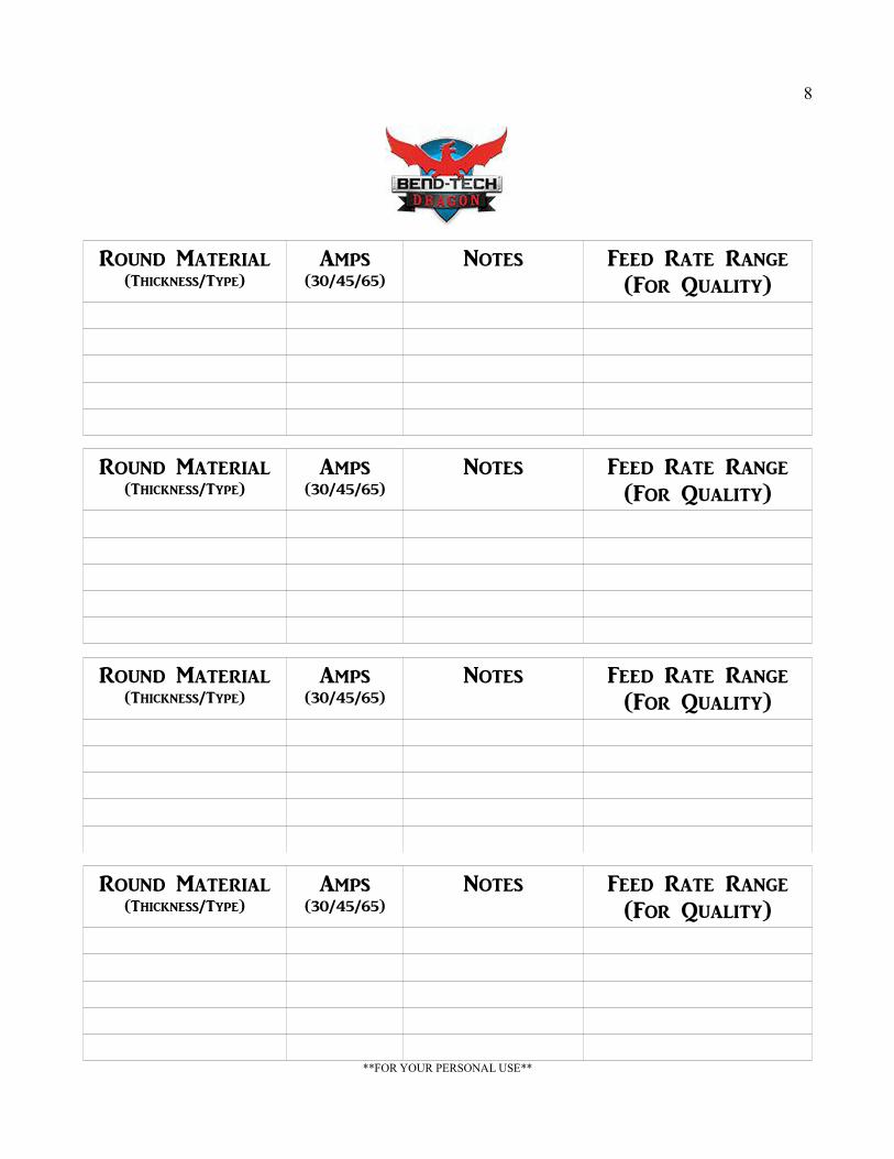
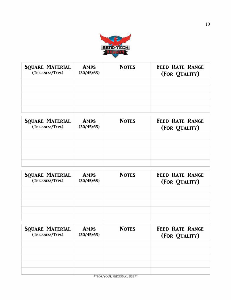
Cutting Speed Recommendations:• The charts (located on pages 8-11) are meant as an option for you to log your
personal values for feed rates and amperage based on the knowledge that changes will vary depending on material type, wall thickness, shape of material and other factors.
• Differences in consumables, torch capacities and shop environment can change your inputted settings from their originals.
----------------------------------------------------------------------------------------------------------------------------Torch Manual Charts:
• Regardless of your manufacturer of plasma torch, there will be cutting charts located in your torch manual. We suggest using these cutting charts for enteringyour speed information into our software, but with a few things in mind.
1. When entering speed values, you must consider the rotational axis of your new machine and decrease the speed and amperage settings on your torch in the case thatyour cut quality is less than desired. The Dragon machine can cut round material at higher speeds because it can rotate the tubing in a single fluid motion.
7
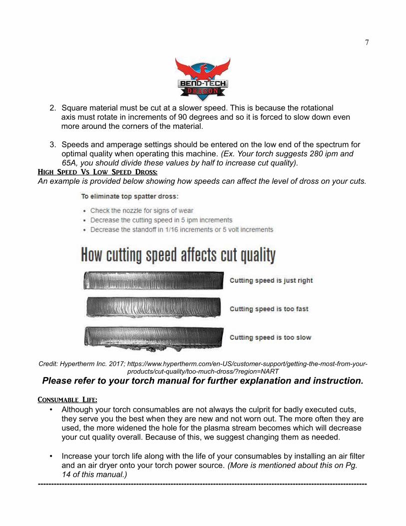
2. Square material must be cut at a slower speed. This is because the rotational axis must rotate in increments of 90 degrees and so it is forced to slow down even more around the corners of the material.
3. Speeds and amperage settings should be entered on the low end of the spectrum for optimal quality when operating this machine. (Ex. Your torch suggests 280 ipm and 65A, you should divide these values by half to increase cut quality).
High Speed Vs Low Speed Dross:An example is provided below showing how speeds can affect the level of dross on your cuts.
Credit: Hypertherm Inc. 2017; https://www.hypertherm.com/en-US/customer-support/getting-the-most-from-your-products/cut-quality/too-much-dross/?region=NART
Please refer to your torch manual for further explanation and instruction.
Consumable Life:• Although your torch consumables are not always the culprit for badly executed cuts,
they serve you the best when they are new and not worn out. The more often they are used, the more widened the hole for the plasma stream becomes which will decrease your cut quality overall. Because of this, we suggest changing them as needed.
• Increase your torch life along with the life of your consumables by installing an air filter and an air dryer onto your torch power source. (More is mentioned about this on Pg. 14 of this manual.)
----------------------------------------------------------------------------------------------------------------------------
8
Round Material(Thickness/Type)
Amps(30/45/65)
Notes Feed Rate Range(For Quality)
Round Material(Thickness/Type)
Amps(30/45/65)
Notes Feed Rate Range(For Quality)
Round Material(Thickness/Type)
Amps(30/45/65)
Notes Feed Rate Range(For Quality)
Round Material(Thickness/Type)
Amps(30/45/65)
Notes Feed Rate Range(For Quality)
**FOR YOUR PERSONAL USE**

9
Round Material(Thickness/Type)
Amps(30/45/65)
Notes Feed Rate Range(For Speed)
Round Material(Thickness/Type)
Amps(30/45/65)
Notes Feed Rate Range(For Speed)
Round Material(Thickness/Type)
Amps(30/45/65)
Notes Feed Rate Range(For Speed)
Round Material(Thickness/Type)
Amps(30/45/65)
Notes Feed Rate Range(For Speed)
**FOR YOUR PERSONAL USE**
10
Square Material(Thickness/Type)
Amps(30/45/65)
Notes Feed Rate Range(For Quality)
Square Material(Thickness/Type)
Amps(30/45/65)
Notes Feed Rate Range(For Quality)
Square Material(Thickness/Type)
Amps(30/45/65)
Notes Feed Rate Range(For Quality)
Square Material(Thickness/Type)
Amps(30/45/65)
Notes Feed Rate Range(For Quality)
**FOR YOUR PERSONAL USE**

11
Square Material(Thickness/Type)
Amps(30/45/65)
Notes Feed Rate Range(For Speed)
Square Material(Thickness/Type)
Amps(30/45/65)
Notes Feed Rate Range(For Speed)
Square Material(Thickness/Type)
Amps(30/45/65)
Notes Feed Rate Range(For Speed)
Square Material(Thickness/Type)
Amps(30/45/65)
Notes Feed Rate Range(For Speed)
**FOR YOUR PERSONAL USE**
12
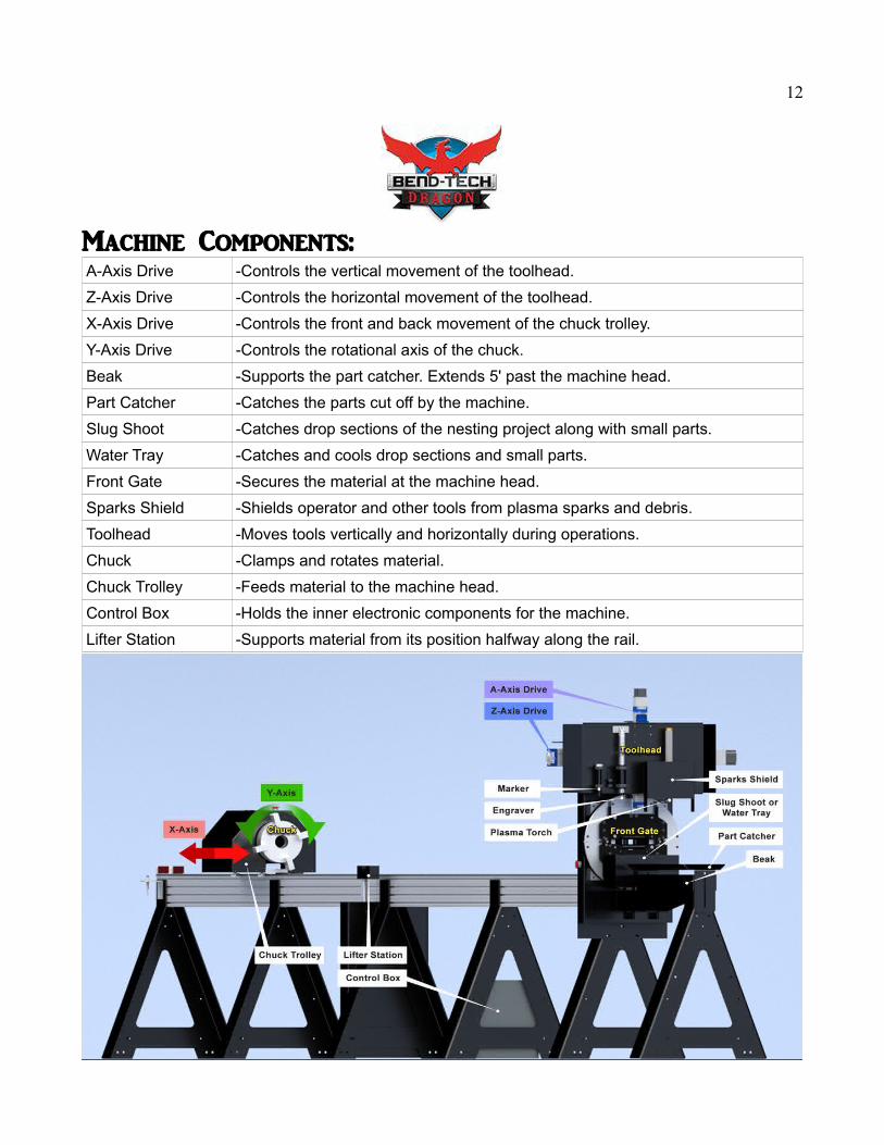
Machine Components:A-Axis Drive -Controls the vertical movement of the toolhead.
Z-Axis Drive -Controls the horizontal movement of the toolhead.
X-Axis Drive -Controls the front and back movement of the chuck trolley.
Y-Axis Drive -Controls the rotational axis of the chuck.
Beak -Supports the part catcher. Extends 5' past the machine head.
Part Catcher -Catches the parts cut off by the machine.
Slug Shoot -Catches drop sections of the nesting project along with small parts.
Water Tray -Catches and cools drop sections and small parts.
Front Gate -Secures the material at the machine head.
Sparks Shield -Shields operator and other tools from plasma sparks and debris.
Toolhead -Moves tools vertically and horizontally during operations.
Chuck -Clamps and rotates material.
Chuck Trolley -Feeds material to the machine head.
Control Box -Holds the inner electronic components for the machine.
Lifter Station -Supports material from its position halfway along the rail.
13
Machine Uncrating and Installation:Safety and Inspection:
• WARNING: SUFFOCATION HAZARD! Immediately discard any plastic bags, wrapping and packing materials to eliminate choking and suffocation hazards to children and animals.
• Inspecting your machine is an important and necessary measure to ensure that you have received your machine with all of its components. Be sure to contact a Bend-TechLLC. Representative in the case that you are missing anything, or your machine has incurred damages during shipping.
• If any parts are missing, DO NOT plug in the power cable, or turn the power switch on until the missing parts are obtained and installed correctly.
• Installation of your machine raises a few questions: Can I lift these heavier machine sections? Where will I put the machine? Is my shop floor level enough? Etc.Here are some answers from our specialists.
Heavy Lifting:• Certain sections of the machine are going to be heavier than others and will require
the use of another set of hands or a hand truck/dolly to maneuver off of the shipping crate. We have a recommended method of moving these parts illustrated in our Assembly Manual (sent separately as a link in the Setup Checklist).
• CAUTION: Always be sure to lift with your legs and not your back. Be sure to use common sense and recognize when sections of the machine are too heavy to lift without another person or without the use of a forklift. DO NOT attempt to uncrate this machine on your own.
• CAUTION: The machine legs and other components may have SHARP EDGES. Wear protective gloves and steel toe boots to protect your hands from cuts and yourfeet in the event that you drop a machine section on your foot.
• BE AWARE of TOP HEAVY sections of the machine. It is recommended to have one person strictly dedicated to maintaining the balance of machine sections during the uncrating process.
Placement in the Shop:• The best location to place your machine is going to be completely up to you, but be
sure to consider the machine dimensions (on pg. 6 of this manual) and keep in mind the length of tubing/parts that will be ran on the machine.
• It should also be noted that electrical interference can be caused due to a closeproximity to other machinery, so distance from other shop equipment is recommended.
14
Leveling and Anchoring:• This product comes equipped with leveling feet to ensure that your machine sections
make up for the different heights and slopes of your shop floor and anchoring brackets so that you can anchor your machine once the machine is leveled. It is highlyrecommended to level the machine during the assembly process and anchor it to the floor afterwards to maintain stability. (See the Assembly Manual for illustrations).
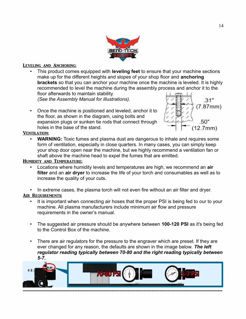
• Once the machine is positioned and leveled, anchor it tothe floor, as shown in the diagram, using bolts andexpansion plugs or sunken tie rods that connect throughholes in the base of the stand.
Ventilation:• WARNING: Toxic fumes and plasma dust are dangerous to inhale and requires some
form of ventilation, especially in close quarters. In many cases, you can simply keep your shop door open near the machine, but we highly recommend a ventilation fan or shaft above the machine head to expel the fumes that are emitted.
Humidity and Temperature:• Locations where humidity levels and temperatures are high, we recommend an air
filter and an air dryer to increase the life of your torch and consumables as well as to increase the quality of your cuts.
• In extreme cases, the plasma torch will not even fire without an air filter and dryer.Air Requirements:
• It is important when connecting air hoses that the proper PSI is being fed to our to yourmachine. All plasma manufacturers include minimum air flow and pressure requirements in the owner’s manual.
• The suggested air pressure should be anywhere between 100-120 PSI as it's being fedto the Control Box of the machine.
• There are air regulators for the pressure to the engraver which are preset. If they are ever changed for any reason, the defaults are shown in the image below. The left regulator reading typically between 70-80 and the right reading typically between5-7.
----------------------------------------------------------------------------------------------------------------------------

15
Wiring Diagrams and Paths:WARNING: DO NOT attempt to remove any wires from this control box while the machine is plugged in and powered on. You risk causing permanent damage to the cables and their plugs.
Machine Control Box:
16
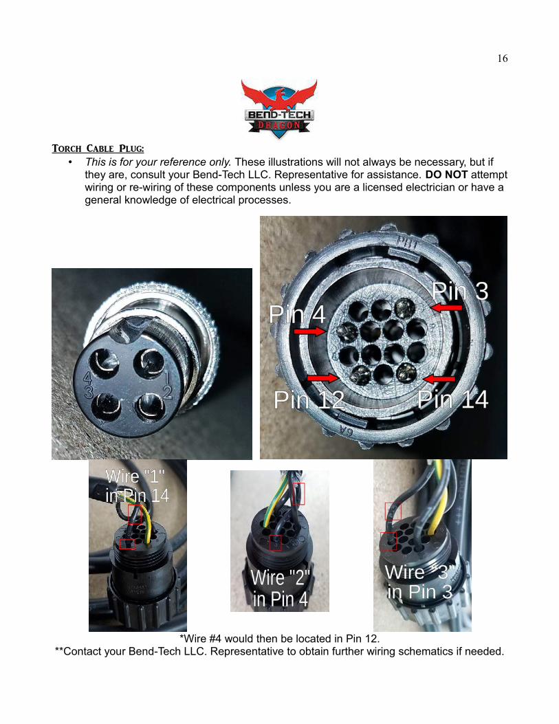
Torch Cable Plug:• This is for your reference only. These illustrations will not always be necessary, but if
they are, consult your Bend-Tech LLC. Representative for assistance. DO NOT attemptwiring or re-wiring of these components unless you are a licensed electrician or have a general knowledge of electrical processes.
*Wire #4 would then be located in Pin 12.**Contact your Bend-Tech LLC. Representative to obtain further wiring schematics if needed.
17
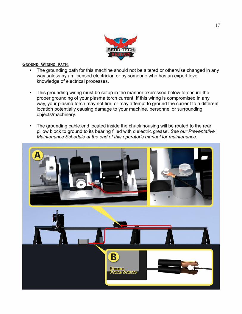
Ground Wiring Path:• The grounding path for this machine should not be altered or otherwise changed in any
way unless by an licensed electrician or by someone who has an expert level knowledge of electrical processes.
• This grounding wiring must be setup in the manner expressed below to ensure the proper grounding of your plasma torch current. If this wiring is compromised in any way, your plasma torch may not fire, or may attempt to ground the current to a differentlocation potentially causing damage to your machine, personnel or surrounding objects/machinery.
• The grounding cable end located inside the chuck housing will be routed to the rear pillow block to ground to its bearing filled with dielectric grease. See our Preventative Maintenance Schedule at the end of this operator's manual for maintenance.
18
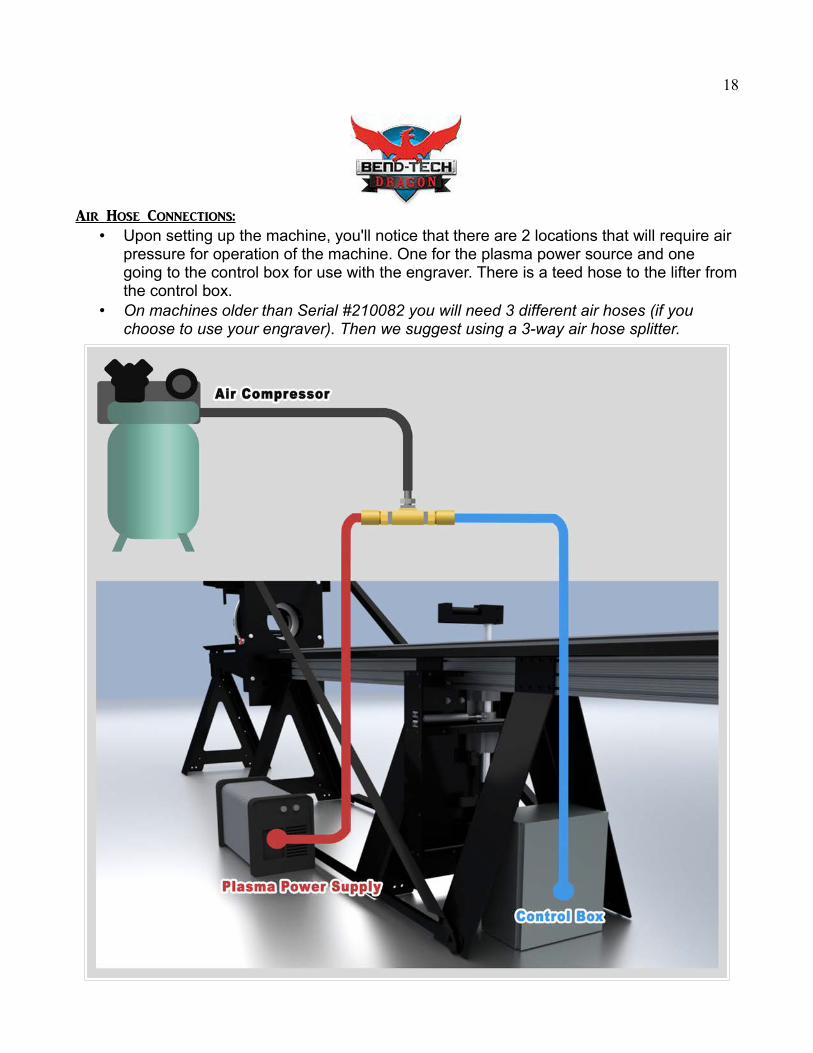
Air Hose Connections:• Upon setting up the machine, you'll notice that there are 2 locations that will require air
pressure for operation of the machine. One for the plasma power source and one going to the control box for use with the engraver. There is a teed hose to the lifter fromthe control box.
• On machines older than Serial #210082 you will need 3 different air hoses (if you choose to use your engraver). Then we suggest using a 3-way air hose splitter.

19
General Machine Operations:Powering on/Powering Off Sequence:
The sequence in which the machine/hardware and software are turned on and off is important. Please follow the instructions as shown here:
Powering on Sequence Powering Off Sequence (Suggested)
1. Power on the Dragon machine using the power switch on the Control Box.
1. Shutdown the Mach 3 software.
2. Start up the Bend-Tech Dragon CAM software on your computer.
2. Shutdown the Dragon CAM software.
3. Start the Mach 3 software on your computer.
3. Power off the Dragon machine using the power switch on the control box.
4. Power on your plasma torch (and ensure that the air compressor is on and airline is attached). It is important that this step comes last to ensure that the torch does not fire due to phantom surges in the startup sequence. Serious injury, dismemberment or death may occur if these steps are not followed strictly.
4. Power off your plasma torch. The orderof this step is irrelevant.
Homing the Machine: When?
1. Home the machine after every time it is turned on.
2. Home the machine after every time Mach 3 is turned on.
3. Home the machine in the event of a Mach 3 time out.
4. Home the machine in the event of a machine crash/failure.
5. Home the machine after any time the emergency stop button is pushed on the machine.
----------------------------------------------------------------------------------------------------------------------------
20
Using the Machine Controller:
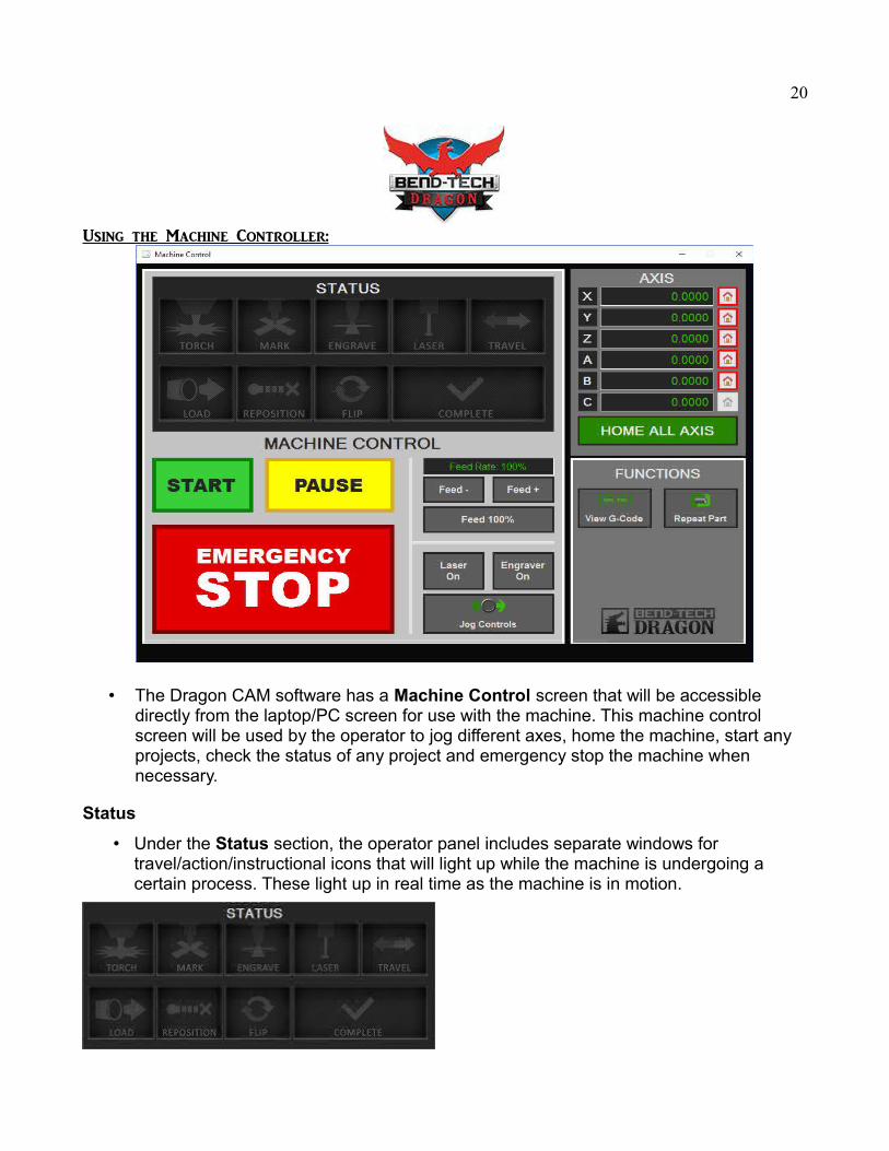
• The Dragon CAM software has a Machine Control screen that will be accessible directly from the laptop/PC screen for use with the machine. This machine control screen will be used by the operator to jog different axes, home the machine, start any projects, check the status of any project and emergency stop the machine when necessary.
Status
• Under the Status section, the operator panel includes separate windows for travel/action/instructional icons that will light up while the machine is undergoing a certain process. These light up in real time as the machine is in motion.

21
Machine Control
• Under the Machine Control section, users will have the means to Start, Pause and Stop a project that has been transferred to the machine, adjust feed rates using the Feed +, Feed - and Feed 100% buttons, and turn on the Laser, Engraver and Jog Controls. Jogging controls are explained below.
Jog Controls
• Click on the Jog Controls to move the machine manually along its different axes.
22
• The Jog Controls move the machine in the following directions:
X: The front and back movement of the chuck trolley.
Y: The clockwise and counter-clockwise rotation movement of the chuck.
Z: The left and right movement of the tool head.
A: The up and down movement of the tool head.
• You can also change the jog rate on a percentage scale by clicking the -10 or +10 buttons in the Set Jog Rate section.
• Click the Close button from below in order to close the jog controls and reveal the Start and Pause buttons again.
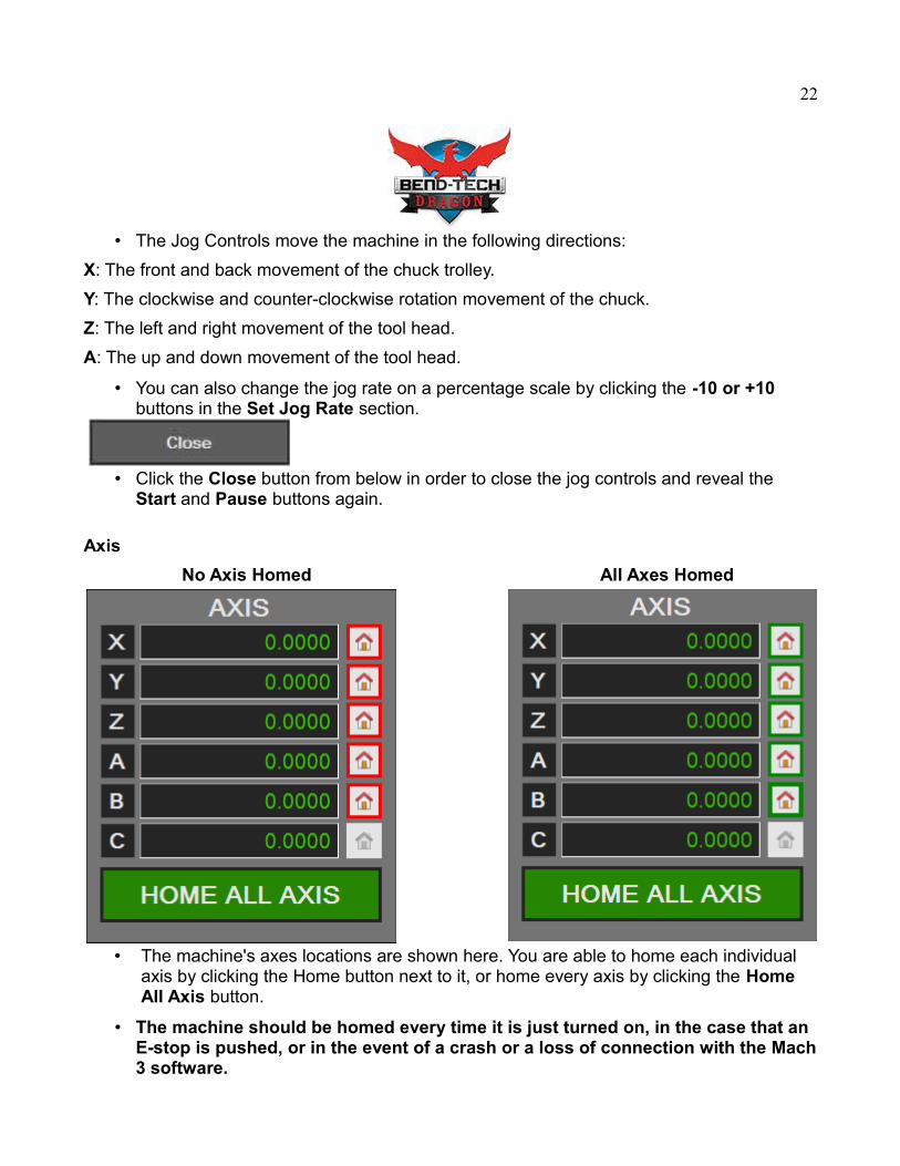
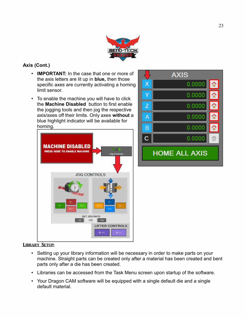
Axis
No Axis Homed All Axes Homed
• The machine's axes locations are shown here. You are able to home each individual axis by clicking the Home button next to it, or home every axis by clicking the Home All Axis button.
• The machine should be homed every time it is just turned on, in the case that an E-stop is pushed, or in the event of a crash or a loss of connection with the Mach3 software.
23
Axis (Cont.)
• IMPORTANT: In the case that one or more ofthe axis letters are lit up in blue, then thosespecific axes are currently activating a hominglimit sensor.
• To enable the machine you will have to clickthe Machine Disabled button to first enablethe jogging tools and then jog the respectiveaxis/axes off their limits. Only axes without ablue highlight indicator will be available forhoming.
Library Setup:
• Setting up your library information will be necessary in order to make parts on your machine. Straight parts can be created only after a material has been created and bentparts only after a die has been created.
• Libraries can be accessed from the Task Menu screen upon startup of the software.
• Your Dragon CAM software will be equipped with a single default die and a single default material.
24
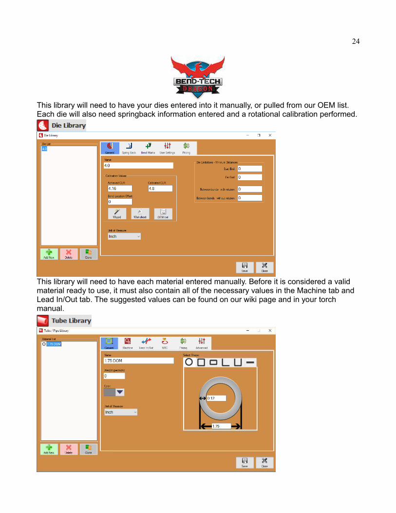
This library will need to have your dies entered into it manually, or pulled from our OEM list. Each die will also need springback information entered and a rotational calibration performed.
This library will need to have each material entered manually. Before it is considered a valid material ready to use, it must also contain all of the necessary values in the Machine tab and Lead In/Out tab. The suggested values can be found on our wiki page and in your torch manual.
25
Gate Operations:
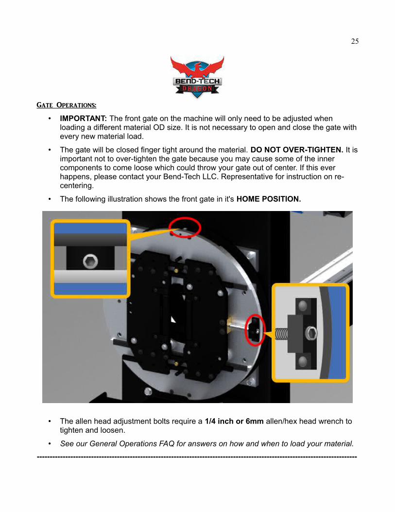
• IMPORTANT: The front gate on the machine will only need to be adjusted when loading a different material OD size. It is not necessary to open and close the gate withevery new material load.
• The gate will be closed finger tight around the material. DO NOT OVER-TIGHTEN. It isimportant not to over-tighten the gate because you may cause some of the inner components to come loose which could throw your gate out of center. If this ever happens, please contact your Bend-Tech LLC. Representative for instruction on re-centering.
• The following illustration shows the front gate in it's HOME POSITION.
• The allen head adjustment bolts require a 1/4 inch or 6mm allen/hex head wrench to tighten and loosen.
• See our General Operations FAQ for answers on how and when to load your material.
----------------------------------------------------------------------------------------------------------------------------
26
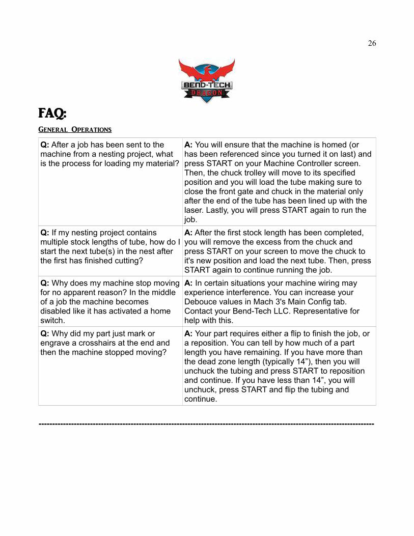
FAQ:General Operations
Q: After a job has been sent to the machine from a nesting project, what is the process for loading my material?
A: You will ensure that the machine is homed (or has been referenced since you turned it on last) and press START on your Machine Controller screen. Then, the chuck trolley will move to its specified position and you will load the tube making sure to close the front gate and chuck in the material only after the end of the tube has been lined up with the laser. Lastly, you will press START again to run the job.
Q: If my nesting project contains multiple stock lengths of tube, how do Istart the next tube(s) in the nest after the first has finished cutting?
A: After the first stock length has been completed, you will remove the excess from the chuck and press START on your screen to move the chuck to it's new position and load the next tube. Then, press START again to continue running the job.
Q: Why does my machine stop movingfor no apparent reason? In the middle of a job the machine becomes disabled like it has activated a home switch.
A: In certain situations your machine wiring may experience interference. You can increase your Debouce values in Mach 3's Main Config tab. Contact your Bend-Tech LLC. Representative for help with this.
Q: Why did my part just mark or engrave a crosshairs at the end and then the machine stopped moving?
A: Your part requires either a flip to finish the job, or a reposition. You can tell by how much of a part length you have remaining. If you have more than the dead zone length (typically 14”), then you will unchuck the tubing and press START to reposition and continue. If you have less than 14”, you will unchuck, press START and flip the tubing and continue.
----------------------------------------------------------------------------------------------------------------------------
27
FAQ:Cut Quality
Q: Why are my cuts not penetrating all the way through my tubing? It's not dropping my parts off.
A: Your feed rate is either set too high, or your amperage on your torch is too low, or it is a combination of both.
Q: Why are my cuts coming out with molten bubbles of metal on the ends or it's melting the tubing back together during cutting?
A: Your feed rate is either set too low, or your amperage on your torch is too high, or it is a combination of both.
Q: Why is my torch dragging on one side of the tubing but not the others? (For square or rectangular tubing only).
A: Usually this is because of differences in tube OD, warping or imperfections in the tubing itself, or your torch height was calibrated incorrectly, but in other cases the front gate may have come out of center. In this case, contact your Bend-Tech LLC. Representative for instruction.
Q: Why does my torch stop firing in the middle of a cut?
A: Usually this is because the torch tip is too far away from the tubing at one point, but it can also bedue to worn out consumables, poor (wet) air being fed to the torch, or water in your air compressor. We always recommend an air filter and an air dryer for your torch power source.
Q: Why doesn't my torch fire at all? A: Either you re-assembled it incorrectly after removing the brass teeth, your consumables are bad, you have humidity in your air lines, your torch is broken or there is a loose or broken wire in your torch cable. In the last case, please contact a Bend-Tech LLC. Representative for instruction or part replacement.
Q: Why do my cuts only complete part of the way around the cutting path?
A: Either your feed rate for rotation is set too high causing your rotational motor to skip steps internally, you have a larger OD tube chucked compared to what you've designed, or you have a loose set screw in your Y-axis assembly (inside the chuck cover) in which case you should contact yourBend-Tech LLC. Representative for instruction.
28
DRAGON A400 Preventative Maintenance Guide
When you hear the phrase "preventive maintenance" what comes to mind? Do you cringe at the thought of taking your Dragon machine out of production, losing precious time and money? Or are you meticulous about taking care of your investment so it will last a very long time? Here are some preventive maintenance (PM) tips to help keep your Dragon machine running at peak performance while avoiding unplanned downtime.
Daily care of your Bend-Tech Dragon machine
1. Blow out front gate bearings and roller bearings with air hose and then lubricate them (and Lifter station roller bearings if applicable). *Use Brake cleaner if build up is considerable.
2. If your machine has a cooling system, make sure the coolant is at the rightoperating level.
3. Clean the slag and plasma dust out of the part catcher.
4. Check the machine's air pressure regulator for proper pressure.
5. Check computer cords for connectivity.
6. Check dust collector bins/bags (if equipped) and empty if needed.
7. Examine tools before cutting. Change consumables as needed.
8. Sweep work area and keep free of debris.
9. Follow your plasma system maintenance guides.
Every Week or 40 working hours
1. Wipe off excess grease.
2. Double check all electronic and mechanical connections.
3. Clean main rail and chuck trolley bearings of the machine. Lightly re-apply white lithium grease to the chuck head and rail section slats.
29
Every Month or 150 working hours
1. Check for loose bolts on machine and tighten as needed.
2. Have cooling system drained and refilled (if equipped).
Every three Months or 500 working hours
1. Check all axes for tightness and grease them down.
2. If the grounding cable for your machine is attached to the pillow block in the chuck housing, add one pump of dielectric grease to the pillow block using a grease gun. If your machine grounds to the mounting block below the chuck spindle, check the grounding brushes inside the chuck housing and replace them if needed.
3. Check and clean the filters on the coolant system (if equipped).
4. Clean overall machine.
Every six Months or 1000 working hours
1. Have the chuck and jaws taken off the machine and cleaned.
2. Have the leveling of your machine checked and adjust if necessary. This will require a re-calibration of the machine. (Located in Machine Library → Wizard → Perform Full Calibration}
Once a Year or every 2000 working hours
1. Run a backlash program to check the backlash in X, Z, and A axis and adjust if necessary.
2. Use a belt tension gauge* to test the tension of the X-drive belt. The value for tension should be between 100-120 lbs.
*Purchase belt tension gauge here: https://www.mcmaster.com/#5913t1/=1aqmfcw
-----------------------------------------------------------------------------------------------------------
30
Of course, no one wants to have their Dragon machine down without a reason because if your machine is not making parts you're losing time andmoney. But if you have a preventive maintenance program in place this allows you to manage your schedule rather than getting caught with untimely surprises. I hope you find this checklist useful for ensuring your machine's everyday productivity and longevity. Your Bend-Tech Dragon machine is just like anything else - if you take care of it, it will take care of you. Is PM a way of life at your shop? Let us know how you approach it. And feel free to contact us if you have any questions about the preventative maintenance on your machine.
When to Call an Expert
Most preventive maintenance tasks listed in this article can be performed by the end user, but there are times when it is important to call a Bend-Tech Dragon Representative for help.
Bend-Tech Dragon Support TeamBend-Tech LLC.
Phone: 1-651-257-8715Address: 729 Prospect Ave. Osceola, WI, 54020
E-Mail: [email protected]@bend-tech.com
You need to be on our Maintenance Plan in order to receive our technical support & software updates. Your Dragon machine comes standard with 2 yearsof Maintenance Plan paid, after that, you will be able to renew your plan annually by contacting one of Bend-Tech's sales personnel.
----------------------------------------------------------------------------------------------------------------------------

31
Thank you for purchasing your new Dragon A400 Unit.
If you have questions or concerns please contact a Bend-Tech representative using
the information provided below.
Bend-Tech Dragon Support TeamBend-Tech LLC.1-651-257-8715
[email protected]@bend-tech.com
http://www.bendtechdragon.com