Embed Size (px)
Citation preview
DRAFT
1
Workplace Safety and Health Guidelines Safe Use of Machinery
DRAFT
2
Contents 1 Introduction .............................................................................................................................. 4
1.1 Scope and Objective 4
1.2 Machinery Life Cycle 4
1.3 Legislation on Machinery Safety 4
2 Risk Management for Machines ............................................................................................... 6
2.1 Risk Assessment 6
2.2 Risk Management and Management of Change 10
3 Identifying Machine Hazards .................................................................................................. 11
3.1 Mechanical Hazards 11
3.1.1 Entanglement hazards ............................................................................................................. 11
3.1.2 Cutting Hazards ....................................................................................................................... 11
3.1.3 Crushing Hazards ..................................................................................................................... 12
3.1.4 Impact Hazards ........................................................................................................................ 12
3.1.5 Shearing Hazards ..................................................................................................................... 12
3.1.6 Draw-in Hazards ...................................................................................................................... 12
3.2 Non-Mechanical Hazards 14
3.2.1 Noise Hazard ............................................................................................................................ 14
3.2.2 Heat-related Hazard ................................................................................................................ 15
3.2.3 Electrical Hazards ..................................................................................................................... 15
3.2.4 Chemical Hazards .................................................................................................................... 16
3.2.5 Ergonomic Risk Factors ............................................................................................................ 17
3.2.6 Fatigue ..................................................................................................................................... 18
4 Controlling Risks: From Acquisition to Disposal ..................................................................... 19
4.1 Acquisition of Machinery 19
4.2 Installation and Commissioning of Machinery 21
4.2.1 Installation ............................................................................................................................... 21
4.2.2 Commissioning ........................................................................................................................ 21
4.3 Use of Machinery 23
4.4 Maintenance of Machinery 24
4.4.1 Maintenance Programme ........................................................................................................ 24
4.4.2 Training for Maintenance Workers ......................................................................................... 24
4.4.3 Lock-out Tag-out (LOTO) Procedure ........................................................................................ 24
4.4.4 Steps for Restoring a Machine for Operation .......................................................................... 24
DRAFT
3
4.5 Disposal of Machinery 25
5 Control Measures ................................................................................................................... 26
5.1 Risk Control by Inherently Safe Design Measures 26
5.1.1 Safer Machine Design .............................................................................................................. 26
5.1.2 Reduced Man-machine Interaction ......................................................................................... 27
5.2 Risk Control by Safeguarding & Implementation of Complementary Protective Measures 28
5.2.1 Machine Guarding ................................................................................................................... 28
5.2.2 Presence Sensing Safety Devices ............................................................................................. 30
5.2.3 Two-handed Control Device .................................................................................................... 31
5.2.4 Emergency Stop Device ........................................................................................................... 31
5.2.5 Warning Device........................................................................................................................ 31
5.3 Risk Control by Information for Use 32
5.3.1 Safe Work Procedures ............................................................................................................. 32
5.3.2 Energy Lock-out Tag-out .......................................................................................................... 33
5.3.3 Safety Signs .............................................................................................................................. 35
5.3.4 Personal Protective Equipment (PPE)...................................................................................... 36
6 Case Study ............................................................................................................................ 40
6.1 Case Study 1: Worker’s Palm Amputated by Power Press 40
6.2 Case Study 2: Worker’s Palm Crushed by Food Cutting Machine 40
6.3 Case Study 3: Worker’s Fingers Amputated by Table Saw 42
6.4 Case Study 4: Worker’s Palm Crushed by Die-Casting Machine 42
6.5 Case Study 5: Worker’s Thumb Severed by Disc Cutter 44
7 Annex..................................................................................................................................... 45
Annex 1- Sample WSH Checklist for Acquisition of Machinery 45
Annex 2- Sample WSH Checklist for Installation of Machinery 46
Annex 3- Sample WSH Checklist for Commissioning of Machinery 47
Annex 4- Sample WSH Checklist for Use of Machinery 48
Annex 5- Sample WSH Checklist for Maintenance of Machinery 49
Annex 6- Sample WSH Checklist for Disposal of Machinery 50
Annex 7- Establishment of Safe Work Procedures 51
8 References ............................................................................................................................ 52
9 Acknowledgement .................................................................................................................. 53
DRAFT
4
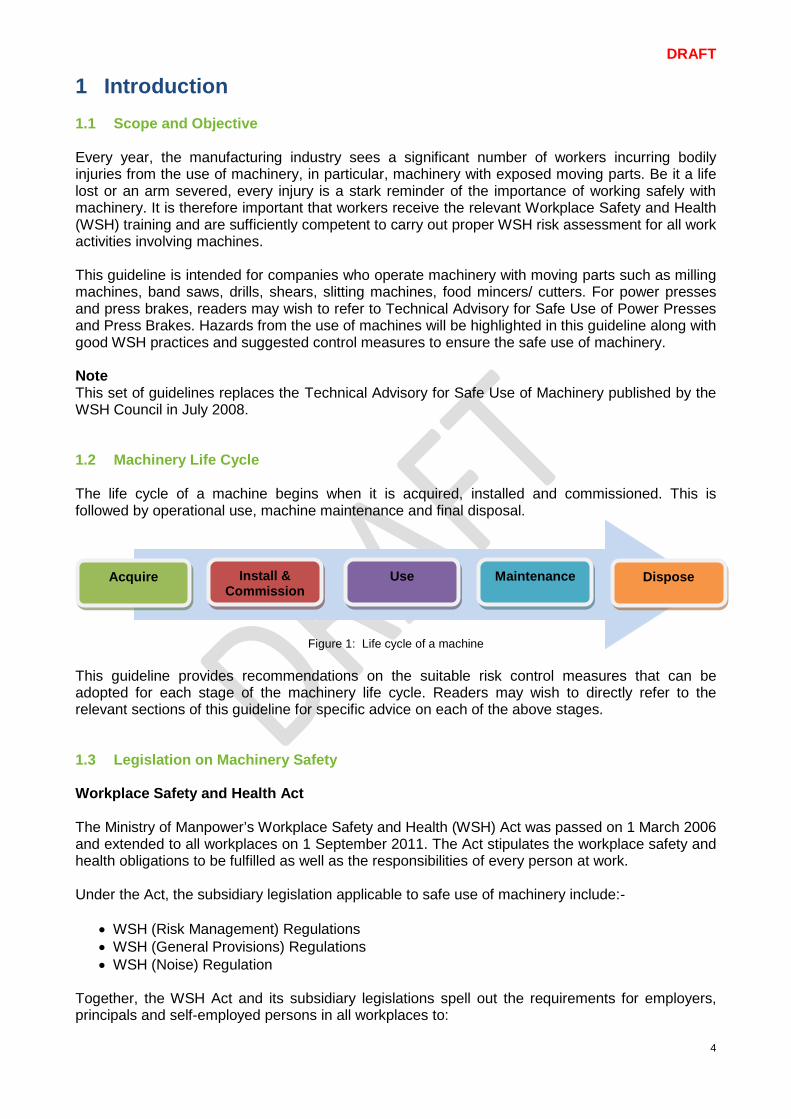
1 Introduction 1.1 Scope and Objective Every year, the manufacturing industry sees a significant number of workers incurring bodily injuries from the use of machinery, in particular, machinery with exposed moving parts. Be it a life lost or an arm severed, every injury is a stark reminder of the importance of working safely with machinery. It is therefore important that workers receive the relevant Workplace Safety and Health (WSH) training and are sufficiently competent to carry out proper WSH risk assessment for all work activities involving machines. This guideline is intended for companies who operate machinery with moving parts such as milling machines, band saws, drills, shears, slitting machines, food mincers/ cutters. For power presses and press brakes, readers may wish to refer to Technical Advisory for Safe Use of Power Presses and Press Brakes. Hazards from the use of machines will be highlighted in this guideline along with good WSH practices and suggested control measures to ensure the safe use of machinery. Note This set of guidelines replaces the Technical Advisory for Safe Use of Machinery published by the WSH Council in July 2008. 1.2 Machinery Life Cycle The life cycle of a machine begins when it is acquired, installed and commissioned. This is followed by operational use, machine maintenance and final disposal.
Figure 1: Life cycle of a machine This guideline provides recommendations on the suitable risk control measures that can be adopted for each stage of the machinery life cycle. Readers may wish to directly refer to the relevant sections of this guideline for specific advice on each of the above stages. 1.3 Legislation on Machinery Safety Workplace Safety and Health Act The Ministry of Manpower’s Workplace Safety and Health (WSH) Act was passed on 1 March 2006 and extended to all workplaces on 1 September 2011. The Act stipulates the workplace safety and health obligations to be fulfilled as well as the responsibilities of every person at work. Under the Act, the subsidiary legislation applicable to safe use of machinery include:-
• WSH (Risk Management) Regulations • WSH (General Provisions) Regulations • WSH (Noise) Regulation
Together, the WSH Act and its subsidiary legislations spell out the requirements for employers, principals and self-employed persons in all workplaces to:
Install & Commission
Acquire Use Maintenance Dispose
DRAFT
5
• conduct risk assessments to identify and control WSH risks • provide safe work facilities and arrangements for workers • ensure safety in machinery, equipment, substances used and work activities carried out • provide adequate instruction, information, training and supervision to workers • implement risk control measures for dealing with emergencies
The WSH (General Provisions) Regulations includes provisions for protecting workers and employed persons when using machinery. Under the law, it is the duty of the occupier of a workplace to ensure that every dangerous part of any machinery in the workplace is securely fenced unless safe by position or constructed safely; or made safe by other effective means when in motion or in use. The law also requires lock-out tag-out procedures to be established and implemented during machine inspection, cleaning, repair and maintenance. This is because a machine, if inadvertently activated or energised, is liable to cause bodily injury to any person at work. Machinery may generate noise in all workplaces. To protect persons at work from being exposed to excessive noise, the WSH (Noise) Regulations requires the occupier of the workplace and the responsible person to implement measures to reduce or control the noise emitted from any machinery. Other relevant regulations include:- The WSH (First-Aid) Regulations stipulates the requirement for every workplace to be provided with a sufficient number of adequately equipped first-aid boxes. It is also compulsory for every person who is appointed a first aider in a workplace to have completed an Occupational First Aid Course. Under the WSH (Incident Reporting) Regulations, it is the duty of the employer or occupier to report any (i) workplace accident leading to fatality or injury, (ii) incidence of occupational disease, or (iii) any dangerous occurrence to the Ministry of Manpower via www.mom.gov.sg/ireport. More detail on the WSH Act and its regulatory framework can be found here:- www.mom.gov.sg/workplace-safety-health/wsh-regulatory-framework/
DRAFT
6
2 Risk Management for Machines
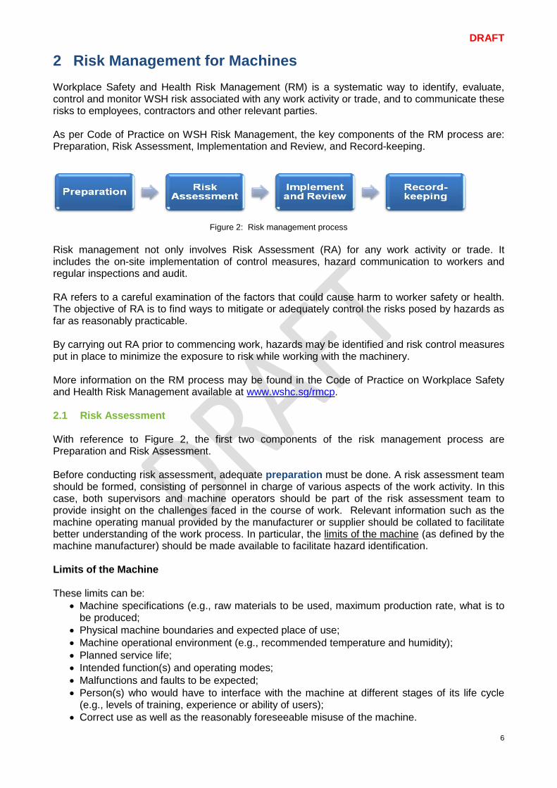
Workplace Safety and Health Risk Management (RM) is a systematic way to identify, evaluate, control and monitor WSH risk associated with any work activity or trade, and to communicate these risks to employees, contractors and other relevant parties. As per Code of Practice on WSH Risk Management, the key components of the RM process are: Preparation, Risk Assessment, Implementation and Review, and Record-keeping.
Figure 2: Risk management process Risk management not only involves Risk Assessment (RA) for any work activity or trade. It includes the on-site implementation of control measures, hazard communication to workers and regular inspections and audit. RA refers to a careful examination of the factors that could cause harm to worker safety or health. The objective of RA is to find ways to mitigate or adequately control the risks posed by hazards as far as reasonably practicable. By carrying out RA prior to commencing work, hazards may be identified and risk control measures put in place to minimize the exposure to risk while working with the machinery. More information on the RM process may be found in the Code of Practice on Workplace Safety and Health Risk Management available at www.wshc.sg/rmcp. 2.1 Risk Assessment With reference to Figure 2, the first two components of the risk management process are Preparation and Risk Assessment. Before conducting risk assessment, adequate preparation must be done. A risk assessment team should be formed, consisting of personnel in charge of various aspects of the work activity. In this case, both supervisors and machine operators should be part of the risk assessment team to provide insight on the challenges faced in the course of work. Relevant information such as the machine operating manual provided by the manufacturer or supplier should be collated to facilitate better understanding of the work process. In particular, the limits of the machine (as defined by the machine manufacturer) should be made available to facilitate hazard identification. Limits of the Machine These limits can be:
• Machine specifications (e.g., raw materials to be used, maximum production rate, what is to be produced;
• Physical machine boundaries and expected place of use; • Machine operational environment (e.g., recommended temperature and humidity); • Planned service life; • Intended function(s) and operating modes; • Malfunctions and faults to be expected; • Person(s) who would have to interface with the machine at different stages of its life cycle
(e.g., levels of training, experience or ability of users); • Correct use as well as the reasonably foreseeable misuse of the machine.
DRAFT
7
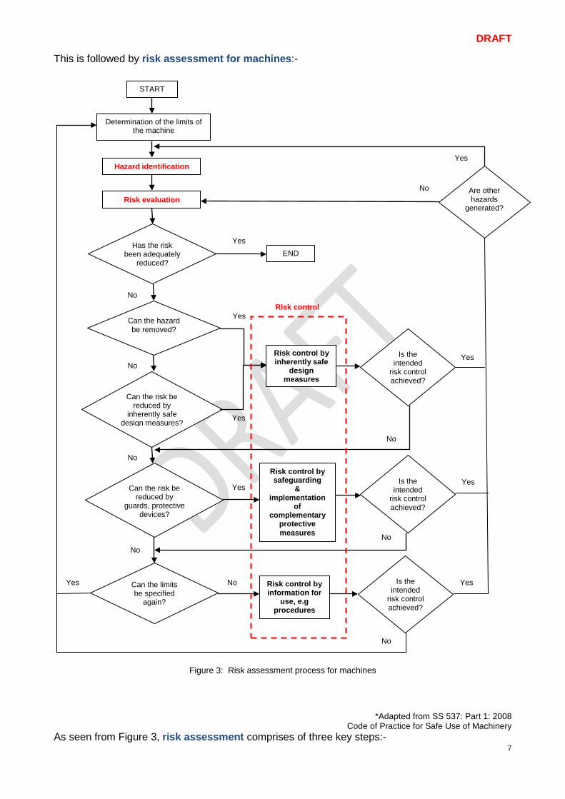
This is followed by risk assessment for machines:-
Figure 3: Risk assessment process for machines
*Adapted from SS 537: Part 1: 2008 Code of Practice for Safe Use of Machinery
As seen from Figure 3, risk assessment comprises of three key steps:-
START
Determination of the limits of the machine
Hazard identification
Risk evaluation
Has the risk been adequately
reduced?
Can the risk be reduced by
inherently safe design measures?
Can the hazard be removed?
Can the risk be reduced by
guards, protective devices?
END
Risk control by inherently safe
design measures
Can the limits be specified
again?
Risk control by safeguarding
& implementation
of complementary
protective measures
Risk control by information for
use, e.g procedures
Are other hazards
generated?
Is the intended
risk control achieved?
Is the intended
risk control achieved?
Is the intended
risk control achieved?
No
No
No
No
Yes
Yes
Yes
Yes
No
Yes
Yes
Yes
No
No
No
Yes
No
Risk control
Yes
DRAFT
8
Step 1: Hazard identification Step 2: Risk evaluation Step 3: Risk control
Key aspects to consider for each step are suggested below:- Step 1: Hazard Identification Hazard Identification involves identifying hazards associated with each work activity (e.g., during routine work, non-routine work and emergency situations) involving the machine along with the potential accidents or ill health that could occur. It also identifies the person(s) who may be at risk as a result of being exposed to the hazards. Additionally, the personal health risk factors (e.g., colour blindness, asthma) of employees working with machines should be considered during hazard identification and suitably addressed in a Risk Assessment. Techniques for hazard identification include team brainstorming, reviewing past incident and injury records, conducting a physical site inspection, carrying out a Job Safety Analysis (JSA), performing a Failure Mode and Effects Analysis (FMEA), etc. A good way of identifying hazards for complex work processes is to first break it down into its major work activities and then to analyse each work activity individually to determine the hazards and the potential accidents and/or adverse health effects which may arise from inadequate control of each hazard. In the case of machinery, the hazards encountered can be broadly classified into 2 major hazard categories:
• Mechanical Hazards • Non-mechanical Hazards
- Please refer to Chapter 3 of this guideline for more insight on these hazards.
Step 2: Risk Evaluation Risk evaluation is the process of estimating the risk level of each work activity involving the machine and determining whether the estimated risk level is acceptable. The results of risk evaluation are used as the basis for prioritising risk control actions to minimize safety and health risks. Risk evaluation is made up of three components: • Assessing the potential SEVERITY of the machine hazard • Determining the LIKELIHOOD of the incident or ill-health that can occur while working with
the machine • Estimating the risk level of the work activity based on its SEVERITY and LIKELIHOOD
Note For more information on Risk Evaluation for work involving machine, please refer to the following:
- Code of Practice on WSH Risk Management - WSH Guidelines on Managing Safety and Health for SMEs in the Metalworking Sector - SS 537: 2008 Code of Practice for Safe use of machinery- Part 1, Section 5.2.5 (Risk
Estimation)
DRAFT
9
Step 3: Risk Control Based on the risk evaluation in Step 2, risk controls should be selected to reduce the estimated risk to an acceptable level. As recommended in Figure 3, risk control measures should be observed in the following order where possible:
• Risk control by inherently safe design measures • Risk control by safeguarding & implementation of complementary protective measures • Risk control by information for use
Risk control by inherently safe design measures Inherent safety can be achieved through inherently safer design. Inherently safer design occurs when machine hazards are excluded at source by designing out the risk(s) faced when working with the machine. Machines can be made safer by manufacturer design through hazard avoidance or risk reduction by careful choice of equipment design features either for the machine itself or to minimise the interaction between man and machine. Some inherently safe design measures include introducing machine automation, substitution of a toxic machining fluid with a less hazardous one, reducing the mechanical force or energy exerted by the machine, designing to block access to moving parts, and eliminating equipment pinch points.
- For more information on risk control by inherently safe design measures, refer to Section 5.1. Risk control by safeguarding & implementation of complementary protective measures These controls are add-on protective measures put in place to reduce the likelihood of occurrence or severity of the consequence of a mishap. These include the erection of a physical safeguarding barrier to interrupt the accident transmission path between the worker and the hazard. Examples of physical barriers that can improve workplace safety and health include installing a machine guard to protect workers from moving equipment parts or enclosing a noise generating machine to protect the hearing of workers.
- For more information on risk control by safeguarding & implementation of complementary protective measures, refer to Section 5.2.
Risk control by information for use These controls help to further reduce exposure to a hazard by adherence to safe work procedures or instructions and should be considered after risk reduction by inherently safer design measures and appropriate safeguarding / implementation of complementary protective measures. Procedure documentation should emphasise the correct steps to be taken and the administrative controls necessary to safely carry out the work activity. Information on hazards and necessary safety precautions that are needed to be taken at specific work areas, especially when working with a hazardous machine should be communicated to workers via safety signs. In addition, information for use includes guidance on selection of appropriate Personal Protective Equipment (PPE) for the task at hand.
- For more information on risk control by information for use, refer to Section 5.3. Further Information − Code of Practice on WSH Risk Management − WSH Guidelines on Managing Safety and Health for SMEs in the Metalworking Industry − A Step-by-Step Guide on Risk Management for Metalworking Sector − SS 537: Part 1: 2008 Code of Practice for Safe Use of Machinery
DRAFT
10
2.2 Risk Management and Management of Change Risk Management Risk assessment is followed by implementation and review where the risk control measures are physically implemented, communicated to all personnel, audited for conformance, and periodically reviewed for effectiveness of the implementation. In the event where work-related ill health, near misses or an accident occurs, an immediate review of the risk assessment is necessary. Otherwise, all risk assessments should be reviewed at least once every three years by default. Risk management includes record-keeping of all relevant records, for example, of RA training sessions, RM implementation audits and RM process management reviews, for a minimum duration of three years. Management of Change As changes to the machinery or its operation (e.g., new machine settings, machine modifications and upgrades, new machine operating procedures, new machine location) may occur after the initial risk assessment is complete, it is important to subject any contemplated changes (whether minor or major, temporary or permanent) to risk assessment to fully ascertain the impact of the change on employee safety and health before being implemented. Written procedures to manage changes should be established and implemented. Considerations to be addressed prior to any change includes technical basis for the proposed change, the update to hazard communication and operating procedures required as a result of the change, the necessary time period for the change to be effected, and the authorisation requirement for the change. All personnel whose job tasks will be affected by the change must be made aware of the change and receive necessary training to handle the change before the change is implemented.
DRAFT
11
3 Identifying Machine Hazards Risk assessment begins with hazard identification. Machine hazards can be divided into mechanical hazards and non-mechanical hazards. 3.1 Mechanical Hazards Many machines have moving parts. Machine parts may move in a linear, reciprocating, rotary, or oscillating motion, individually or in combination. In many cases, the action of these moving parts can exert sufficient force to cause injury to workers operating the machine. Typical examples of mechanical hazards are given below: 3.1.1 Entanglement hazards Entanglement may arise in the course of work when (i) part of a worker’s body (e.g., hands or feet) or (ii) loose items worn by a worker (e.g., clothing or gloves) comes into direct contact with a moving machine part. In general, entanglement may involve: • Contact with a single rotating surface such as couplings, spindles, chucks, leadscrews,
mandrels, bars or any rotating workpiece.
Figure 5: Entanglement caused by contact with a single rotating surface
• Being caught by projections or in gaps such as fan blades, spoked pulleys, chain wheels, gear wheels and flywheels, mixers and beater arms, spiked cylinders, belt fasteners, projecting keys, set screws, cotter pins on shafts or slat conveyors.
Figure 6: Entanglement caused by being caught by projections or in gaps
• Hands being caught in between counter-rotating parts, for example gear wheels, rolling mills,
mixing rolls and calendars, or materials being drawn between two rolls.
Figure 7: Entanglement as a result of being caught in between two counter-rotating parts
3.1.2 Cutting Hazards Cutting hazards are present in machines used to cut wood, metal or other materials at the point of operation. Examples of cutting hazards include all kinds of cutting tools, milling cutters, circular saws, hand saw blades, rotary knives, disc blades, or the sharp edges of a moving sheet of material. Machines or tools with moving cutting elements are particularly dangerous as they have the capability to cause severe injury (e.g., deep cuts, amputations) due to its own momentum when in contact with a worker’s body. The severity becomes magnified when the body part is trapped in a stationary position and unable to move away from the cutting element. Cutting hazards also occur when materials ejected from a machine (e.g., flying metal chips or scrap material) and strike the machine operator.
Figure 8: Examples of cutting hazards
DRAFT
12
3.1.3 Crushing Hazards Crushing occurs when a part of the body is caught:
• Between a fixed and moving part of a machine such as the bed and tool of a power press; • Between two moving parts of a machine such as the support arms of a scissor lift platform; • Between a moving machine part and a fixed structure such as a machine counterweight and
the floor. Figure 9: Examples of crushing hazards
3.1.4 Impact Hazards Impact hazards relate to objects that strike the human body, but do not penetrate it. The severity of an impact hazard is typically a function of the speed, force and inertia of the moving machine part(s) or the material(s) being processed during machine operation or upon ejection from the machine. Examples of impact hazards include being struck by the rotating arm of a robot, struck by the reciprocating bed of a metal planing machine, or being exposed to a high pressure jet of air or water. Impact hazards often result in serious injury such as abrasion and contusions. 3.1.5 Shearing Hazards Parts of machines that move past each other or stationary objects can cause a shear point resulting in a crushing or cutting action. In general, shearing hazards are present:
• Between two machine parts such as a power press punch and die. • Between a machine and a workpiece such as the tool of a broaching machine and its
workpiece.
Figure 10: Examples of shearing hazards 3.1.6 Draw-in Hazards Injuries can occur when a part of the body is drawn-in by in-running nip points, formed by:
• Two counter-rotating parts • A rotating surface and a tangentially moving surface
Figure 11: Examples of draw-in hazards between rotating and tangentially moving surfaces
Recommended Practice
• The WSH risk posed by a machine hazard may be significantly reduced through adequate Risk Control (refer to Figure 3) in the following order of priority: 1) Risk control by inherently safe design measures 2) Risk control by safeguarding and implementation of complementary
protective measures 3) Risk control by information for use
- Chapter 5 of this guideline provides more information on practical measures for each risk control strategy.
• Access to industrial machinery should be strictly restricted to authorised personnel.
• New machine operators must be sufficiently trained and supervised till they are competent to operate the machine on their own.
• All machinery must be regularly serviced, maintained and checked to be

DRAFT
13
in good working condition. • Appropriate personal protective equipment (including overalls, head,
eye, hand and foot protection) must be properly worn when working with machinery. Loose clothing is not allowed and all jewellery (e.g., bracelets, necklaces and rings) must be removed prior to work commencement. Long hair should also be neatly tied up and preferably tucked safely into suitable head wear to prevent entanglement.

DRAFT
14
3.2 Non-Mechanical Hazards When identifying non-mechanical machine hazards, we should consider how machinery can affect the work environment. Some non-mechanical hazards include:- 3.2.1 Noise Hazard Noise is often generated during machine operations and work activities. Prolonged exposure to excessive noise can cause noise-induced hearing loss, leading to noise-induced deafness (NID). To prevent hearing loss, a worker should not be exposed to noise levels exceeding 85 dB (A) for 8 hours a day or its equivalent. Where the permissible exposure level is exceeded, measures must be taken to reduce the noise exposure.
Sound Pressure Level dB(A) Maximum Duration per Day 85 8 hours 88 4 hours 91 2 hours 94 1 hour 97 30 minutes 100 15 minutes 103 7.5 minutes 106 4 minutes 109 2 minutes 111 1 minute
Table 1: Permissible Exposure Limits for Noise extracted from WSH (Noise) Regulations 2011
Recommended Practice
• Specify low noise machinery during equipment purchase. • Replace noisy machinery with less noise machinery. • Relocate noisy machinery and processes to a lesser-occupied or non-
occupied area of the workplace. • Locate noise sources away from hard walls or corners. • Construct suitable noise enclosures or barriers to isolate the noise
source and reduce noise emission. • Minimize the number of noisy machineries running at any one time. • Provide workers with hearing protectors and ensure proper usage.
Further Information − WSH (Noise) Regulations 2011 − WSH Guidelines on Hearing Conservation Programme
DRAFT
15
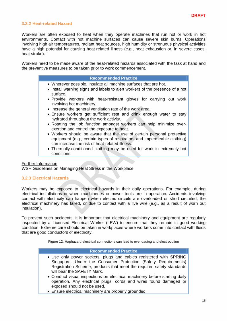
3.2.2 Heat-related Hazard Workers are often exposed to heat when they operate machines that run hot or work in hot environments. Contact with hot machine surfaces can cause severe skin burns. Operations involving high air temperatures, radiant heat sources, high humidity or strenuous physical activities have a high potential for causing heat-related illness (e.g., heat exhaustion or, in severe cases, heat stroke). Workers need to be made aware of the heat-related hazards associated with the task at hand and the preventive measures to be taken prior to work commencement.
Recommended Practice • Wherever possible, insulate all machine surfaces that are hot. • Install warning signs and labels to alert workers of the presence of a hot
surface. • Provide workers with heat-resistant gloves for carrying out work
involving hot machinery. • Increase the general ventilation rate of the work area. • Ensure workers get sufficient rest and drink enough water to stay
hydrated throughout the work activity. • Rotating the job function amongst workers can help minimize over-
exertion and control the exposure to heat. • Workers should be aware that the use of certain personal protective
equipment (e.g., certain types of respirators and impermeable clothing) can increase the risk of heat-related illness.
• Thermally-conditioned clothing may be used for work in extremely hot conditions.
Further Information WSH Guidelines on Managing Heat Stress in the Workplace 3.2.3 Electrical Hazards Workers may be exposed to electrical hazards in their daily operations. For example, during electrical installations or when machineries or power tools are in operation. Accidents involving contact with electricity can happen when electric circuits are overloaded or short circuited, the electrical machinery has failed, or due to contact with a live wire (e.g., as a result of worn out insulation). To prevent such accidents, it is important that electrical machinery and equipment are regularly inspected by a Licensed Electrical Worker (LEW) to ensure that they remain in good working condition. Extreme care should be taken in workplaces where workers come into contact with fluids that are good conductors of electricity.
Figure 12: Haphazard electrical connections can lead to overloading and electrocution
Recommended Practice • Use only power sockets, plugs and cables registered with SPRING
Singapore. Under the Consumer Protection (Safety Requirements) Registration Scheme, products that meet the required safety standards will bear the SAFETY Mark.
• Conduct visual inspections on electrical machinery before starting daily operation. Any electrical plugs, cords and wires found damaged or exposed should not be used.
• Ensure electrical machinery are properly grounded.
DRAFT
16
• Engage only electrical workers that are licensed by the Energy Market Authority to carry out electrical work.
• Establish lock-out tag-out procedures for any work involving the repair and maintenance of electrical machinery.
• Do not clean electrical machinery with flammable solvents. • Do not overload electrical power points. • Ensure electrical machinery are protected by over-current/ overload
protective devices. • Keep power cords away from heat, water and oil. • Always pull the electrical plug, not the cord.
3.2.4 Chemical Hazards Workers carrying out work involving a machine may come into contact with chemicals in their daily activities as many machines rely on the use of chemicals for normal function. For example: • portable electrical generators require the use of diesel as fuel • equipment with moving parts require the use of lubricant to ensure smooth operation • vehicles require the use of hydraulic fluids in their braking mechanism • refrigerators and air-conditioners require the use of a refrigerant to achieve cooling • wafer fabrication requires the use of acids for wet etching • machine maintenance requires the use of specialty cleaning agents When working with a machine, chemical contact with the skin is possible, for example, during the preparation or draining of machine fluids, handling of work pieces, changing and setting of tools, and during cleaning operations. Inhalation is another possible route for chemical exposure. This can occur when one is working near a machine where a chemical mist, aerosol or vapour is generated, where the machine is not enclosed and when ventilation of the work environment is inadequate. Prolonged exposure to chemicals can lead to skin disorders (e.g., dermatitis) and poor respiratory health (e.g., asthma). Occupational exposure due to ingestion is less common but can take place in the following situations: (i) employees not washing their hands properly before drinking, eating or smoking, and (ii) employees drinking or eating in contaminated work areas. A harmful chemical, if swallowed, can cause extensive damage to the inner lining of one’s mouth, gullet and stomach. In the metalworking industry, machining fluids are necessary to reduce friction between the cutting tool and the work surface as well as carry away the generated heat. The use of a machining fluid (a chemical) is critical as it not only helps to improve the machining performance but it also prolongs the life of the cutting tool. Unfortunately, such fluids can splash onto a worker during machine operation if there are no splashguards. The use of chemicals, therefore, poses significant workplace risks as they can be toxic, flammable, corrosive and/ or highly reactive. It is important that this risk be well controlled in order to protect workers from the chemical hazard(s) associated with machine operation. Ideally, hazardous chemicals should be eliminated or substituted with something less hazardous. However, if this is not possible, the use of engineering controls (e.g., a fixed splashguard), administrative controls (e.g., safe work procedures and safety signs), and personal protective equipment (e.g. chemical-resistant aprons and face shields) is strongly recommended to minimise one’s exposure while working with a machine.
DRAFT
17
Recommended Practice
• Eliminate or substitute hazardous chemicals wherever possible • Install an enclosed splashguard to protect workers from splashing due to
machine operation. • Minimise the extent of splashing and mist generation by controlling the
volume and delivery rate of the machining fluid to the cutting tool. • Develop safe work procedures for any work involving a hazardous
chemical • Install safety signage to warn machine users of the presence of a
chemical hazard • Ensure work area is sufficiently ventilated. The use of local exhaust
ventilation (e.g., a fume extraction chamber) is recommended for any machine work where chemical mist, vapours and/ or aerosols are emitted.
• Provide workers with appropriate PPE for the task e.g., chemical-resistant aprons and gloves, safety goggles/ face shields, respirators.
• Train workers not to contaminate the inside of the gloves when putting them on or taking them off.
• Provide hand washing facilities and encourage workers to wash their hands regularly especially before eating or drinking. When washing hands, advise workers to pay particular attention to washing the skin under rings and watch straps.
• Provide laundry service for company-issued work attire so that workers do not bring contaminated clothing home.
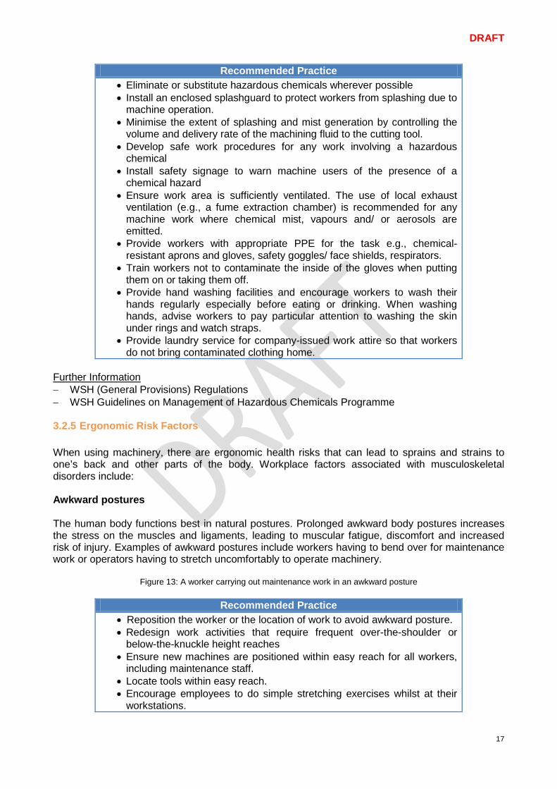
Further Information − WSH (General Provisions) Regulations − WSH Guidelines on Management of Hazardous Chemicals Programme 3.2.5 Ergonomic Risk Factors When using machinery, there are ergonomic health risks that can lead to sprains and strains to one’s back and other parts of the body. Workplace factors associated with musculoskeletal disorders include: Awkward postures The human body functions best in natural postures. Prolonged awkward body postures increases the stress on the muscles and ligaments, leading to muscular fatigue, discomfort and increased risk of injury. Examples of awkward postures include workers having to bend over for maintenance work or operators having to stretch uncomfortably to operate machinery.
Figure 13: A worker carrying out maintenance work in an awkward posture
Recommended Practice • Reposition the worker or the location of work to avoid awkward posture. • Redesign work activities that require frequent over-the-shoulder or
below-the-knuckle height reaches • Ensure new machines are positioned within easy reach for all workers,
including maintenance staff. • Locate tools within easy reach. • Encourage employees to do simple stretching exercises whilst at their
workstations.
DRAFT
18
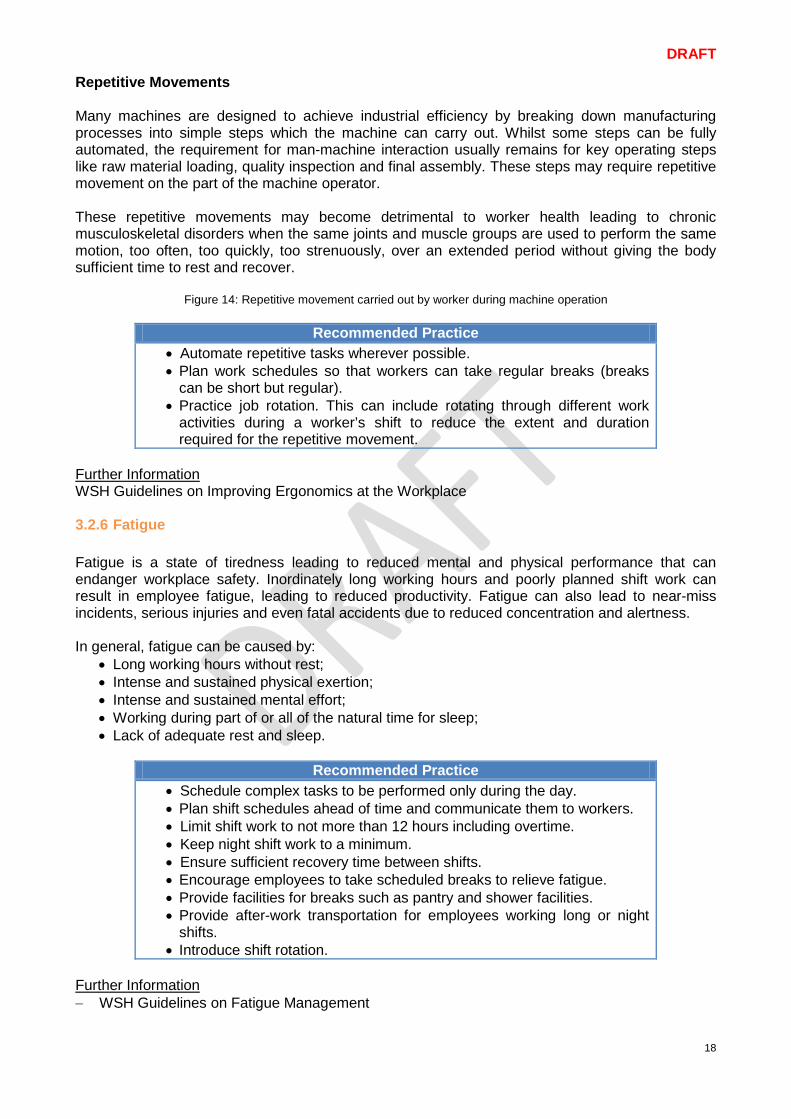
Repetitive Movements Many machines are designed to achieve industrial efficiency by breaking down manufacturing processes into simple steps which the machine can carry out. Whilst some steps can be fully automated, the requirement for man-machine interaction usually remains for key operating steps like raw material loading, quality inspection and final assembly. These steps may require repetitive movement on the part of the machine operator. These repetitive movements may become detrimental to worker health leading to chronic musculoskeletal disorders when the same joints and muscle groups are used to perform the same motion, too often, too quickly, too strenuously, over an extended period without giving the body sufficient time to rest and recover.
Figure 14: Repetitive movement carried out by worker during machine operation
Recommended Practice • Automate repetitive tasks wherever possible. • Plan work schedules so that workers can take regular breaks (breaks
can be short but regular). • Practice job rotation. This can include rotating through different work
activities during a worker’s shift to reduce the extent and duration required for the repetitive movement.
Further Information WSH Guidelines on Improving Ergonomics at the Workplace 3.2.6 Fatigue Fatigue is a state of tiredness leading to reduced mental and physical performance that can endanger workplace safety. Inordinately long working hours and poorly planned shift work can result in employee fatigue, leading to reduced productivity. Fatigue can also lead to near-miss incidents, serious injuries and even fatal accidents due to reduced concentration and alertness. In general, fatigue can be caused by:
• Long working hours without rest; • Intense and sustained physical exertion; • Intense and sustained mental effort; • Working during part of or all of the natural time for sleep; • Lack of adequate rest and sleep.
Recommended Practice
• Schedule complex tasks to be performed only during the day. • Plan shift schedules ahead of time and communicate them to workers. • Limit shift work to not more than 12 hours including overtime. • Keep night shift work to a minimum. • Ensure sufficient recovery time between shifts. • Encourage employees to take scheduled breaks to relieve fatigue. • Provide facilities for breaks such as pantry and shower facilities. • Provide after-work transportation for employees working long or night
shifts. • Introduce shift rotation.
Further Information − WSH Guidelines on Fatigue Management
DRAFT
19
4 Controlling Risks: From Acquisition to Disposal As bringing in a new machine into the work area brings along with it new WSH risks, it is important to carefully evaluate the machinery prior to bringing it on-site, bearing in mind the machinery life cycle (see Section 1.2) starting with acquisition of machinery. 4.1 Acquisition of Machinery Injuries associated with machinery may occur as a result of selecting the wrong machine for the job. Consider the following before purchasing a new machine:
• The intended purpose of the machine • The environment and location in which the machine would be placed • The training and competency requirement for the machine operator • WSH risks arising from the use of the machinery; • How the risks are controlled by different manufacturers and the residual risks that need to be
addressed. The above information can help a purchaser decide which machine(s) may be more suitable, after taking into account WSH considerations. When acquiring new machinery, recommended practice is to ensure that:-
• a background check on the specific machine model has been conducted to ascertain if there are existing WSH concerns.
• adequate inherently safe design measures have been included in the design of the machine (please refer to section 5.1).
• the manufacturer or supplier has provided a Declaration of Conformity. • risk assessment has been carried out by the machine manufacturer or supplier. • an operating manual has been supplied which includes instructions for safe machine use,
assembly, installation, commissioning, repair and maintenance. • technical drawings of the machine and its various parts are available. • information on any residual risks has been provided along with the safety precautions
needed to deal with them. • certified safety marks are present as evidence of machine conformance to applicable local
and/ or international standards as required by the company acquiring the machine. Along with the above recommendations, machine purchasers may also consider working closely with the machine manufacturer / supplier to (i) build-in user training sessions (for both operation and in-house maintenance personnel) as part of the purchase cost, and (ii) carry out regular equipment servicing and maintenance on contract terms. A sample checklist on acquiring new machinery can be found in Annex A. Declaration of Conformity A declaration of conformity is a formal declaration by a manufacturer or supplier, that the machine meets all local safety requirements and relevant international standards applicable to that machine. The declaration assures that the machine has been designed and constructed for conformance with relevant safety requirements and has been through the appropriate conformity assessment processes. A declaration of conformity, however, is not a certificate of quality nor a guarantee for safety. The declaration of conformity typically includes the following:
• Name and address of the manufacturer (or, where appropriate, the authorised representative)
DRAFT
20
• Information on machine model, type and serial number • Applicable safety requirements and standards to which the machine conforms to • Identity and signature of the person empowered to draw up the declaration on behalf of the
manufacturer (or the authorised representative) Acquisition of Used Machinery Under the pressure to reduce business cost, companies may not see the need to invest in new machinery. Instead, companies may prefer to acquire used equipment which is still able to meet day-to-day operational requirements. When purchasing second-hand machinery, recommended practice (over and above those earlier listed for new machinery) is to ensure that:-
• machine safe guards and safety devices are present and functioning. • equipment warning signs are visible and easy to understand. • spare parts for the machine are available should part replacement be necessary at a later
stage. • modified or retrofitted machine are certified safe for use.
Additionally, second-hand machinery should be subject to a pre-operational functionality test. The tests should include functional checks on each machine safety feature (e.g., safety interlock, emergency stops). A competent person (e.g., a professional engineer or third-party inspector) may be engaged to assist with an independent and objective safety evaluation. The evaluation would assess the machine for conformance to industry standards and local WSH requirements. As a result of the evaluation, companies will be able to obtain upfront information for making the purchasing decision. Upon acquiring the second-hand machinery, it is the duty of the owner to make sure that the second-hand machinery is:
• Suitable for the selected work • Safe for use • Maintained in a safe condition
A sample checklist on acquiring second-hand machinery can be found in Annex A.
DRAFT
21
4.2 Installation and Commissioning of Machinery 4.2.1 Installation Installation refers to the process in which a machine is assembled, placed in position, connected, and made ready for use. WSH Considerations for installation of machinery:
• All on-site assembly work and installation, including electrical wiring, should be performed by the machine manufacturer, authorised agent or competent person.
• Risk assessment must be conducted prior to the installation work activity. • There should be sufficient space for the unloading and temporary storage of the machine
and its components. • Machine Location and Factory Layout
- Machines should be installed in a location that does not obstruct the fire exits, emergency escape routes, access to firefighting equipment and building access route for firefighting operations.
- Sufficient space should be provided for workers to safely work around each machine and a safe passage provided for workers to move past (or through) groups of machines. Individual machines would require sufficient space to allow for daily work activities including normal operations, cleaning, and maintenance.
- Machines with moving parts should be located a safe distance from any fixed structure. • Any debris or waste material generated from the unpacking and installation process should
be consolidated for proper disposal. Further Information − SS 567: 2011 Code of Practice for Factory layout - Safety, health and welfare considerations 4.2.2 Commissioning Commissioning refers to the advancement of the installation from the stage of static completion to the start-up and full working of the machine. Machinery should be tested and commissioned by the machinery manufacturer, authorised agent or competent person prior to handover to the machine purchaser / owner. When commissioning a machine, the recommended practice is to:-
• Carry out a risk assessment to identify residual hazards and ascertain if the control measures in place are sufficient for safe use of the machinery.
• Confirm that the machine is on level ground and placed firmly on the floor or footing. • Barricade the machine and label with warning signs during commissioning and testing. • Thoroughly inspect the machinery for machine faults or defects, before any energy source is
switched on. In particular, - the appearance of each part should be checked. - the machine should not have any abnormal conditions such as cracks, damages, dents,
foreign items or missing items. - all parts should be fastened properly, and V-belts, timing belts, chains, etc. tensioned
as appropriate. - the lubricant oil, coolant, grease, etc. used are of the correct type recommended by the
manufacturer. • Confirm that the power supply voltage to the machinery is correct, before switching on the
power supply. • Check that there is no leakage of oils or coolants, and that the machine operating pressure is
within the acceptable range with no abnormal noise emissions after the machinery is powered on.

DRAFT
22
• Subject all safety devices (examples below) to a functional check, before the machine can be declared safe for use:
a) Machine guards b) Sensors and interlocking devices of machine guards, gates, doors, etc c) Presence-sensing device d) Two-handed control device e) Emergency stop button f) Warning device g) Circuit breakers
All inspection, testing and commissioning results should be properly documented for future reference.
DRAFT
23
4.3 Use of Machinery Workers who are operating machinery must be trained, competent, and/or suitably supervised, so that they do not put themselves or others at risk while at work. Before commencing operation, it is important to: (i) obtain the latest copy of the completed risk assessment, understand the hazards posed by the
machine and identify the control measures implemented. (ii) carry out pre-operation functionality checks on all machine safety devices (e.g., machine
guards, presence-sensing device, two-handed control devices, interlocking devices and emergency stop button).
When using the machine, operators are expected to (i) confirm that engineering control measures are in place (refer to section 5.2). (ii) adhere to the Safe Work Procedures (SWP) (refer to section 5.3.1). (iii) don the appropriate personal protective equipment (refer to section 5.3.5) such as safety
glasses or goggles should the risk of materials being ejected during operation still exist. Hearing protectors must also be used should there be excessive exposure to noise (above 85 dB(A) over an 8 hours period) while working at the machine.
Employers should also consider and address the risks that may arise from:
• repetitive tasks (refer to Section 3.2.4); • worker fatigue (refer to Section 3.2.5).
WSH Training Employers need to ensure that workers are adequately trained and competent in machine operation and maintenance prior to assigning work. Training may include formal classroom training, on-the-job coaching, as well as specific work instructions to individuals or groups. WSH training should be conducted:
• during orientation of new employees • periodically for existing employees • whenever new machinery or processes are introduced • when an employee is transferred to another department or job function
All training should be properly documented (e.g., date of training, participant list and the topics covered). Once workers have received training in WSH, they should be able to:
• follow the Safe Work Procedures and operate the machine safely • properly use the Personal Protective Equipment • exercise due diligence to report accidents, incidents, near misses or any workplace hazards
to their supervisors • carry out emergency response procedures • participate in WSH management activities
Re-training is necessary, when:
• new machinery is installed or modifications carried out to existing machines, presenting new hazards
• changes are made to the safe work procedures • risk assessment forms are updated and need to be communicated to all employees
Further Information WSH Guidelines on Managing Safety and Health for SMEs in the Metalworking Industry
DRAFT
24
4.4 Maintenance of Machinery In general, machines must be regularly maintained for optimal performance, to prevent breakdowns and to ensure that the machine remains safe for use. Machinery must be maintained and repaired according to manufacturer specifications or, in the absence of such specifications, in accordance with a competent person’s recommendations. As with all work activities, a site specific risk assessment must be carried out before maintenance work is attempted. 4.4.1 Maintenance Programme An effective maintenance programme should be established for all machinery and equipment used. This will help prevent accidents resulting from the failure of machinery or equipment. A maintenance programme should include:-
• A listing of all the machinery and equipment used within each worksite; • Inspection and maintenance schedules and records for each machinery and equipment; • System for employees to report any defective or damaged machine in the course of their
work.
If the machine is not functioning properly, only trained and authorised personnel may be tasked to diagnose the problem with the machine. Replacement parts and devices recommended by the manufacturer should be used in order to maintain the integrity and continued safe use of the machine. The replacement parts need to be properly matched to the machine series, model, serial number and revision of the machine. If original replacement parts are not available, consult the manufacturer for recommendations on suitable alternatives. 4.4.2 Training for Maintenance Workers Authorised personnel performing servicing and maintenance need to be trained to:
• Recognise hazardous energy sources and understand the magnitude of the energy source at hand;
• Identify and properly operate the applicable energy-isolating devices; • Carry out the lock-out and tag-out procedure; • Safely apply and remove lock-out devices.
Machine operators need to be trained to:
• Recognise when the lock-out activities are in progress; • Understand the purpose of the energy lock-out and the importance of not tampering with the
lock-out devices encountered at the workplace. 4.4.3 Lock-out Tag-out (LOTO) Procedure All energy sources (whether electrical, mechanical, pneumatic, hydraulic or in any combination) must be securely isolated before attempting the repair or maintenance of any machinery. This is to ensure that the machinery does not move or accidentally start up due to an unexpected release of an energy source. The steps necessary to isolate all forms of hazardous energy is termed the lock-out tag-out (LOTO) procedure.
- Refer to Section 5.3.4 for more information on Lock-out Tag-out procedure. 4.4.4 Steps for Restoring a Machine for Operation When the repair or maintenance work for a machine is completed, the next step is to restore it for normal operation. Follow the below steps to ensure safety of personnel during machine restoration:
DRAFT
25
1) Check to ensure that all tools have been removed from the machine 2) Confirm that all safeguards and other safety devices have been returned to their original
locations and are functional. 3) Check the immediate vicinity of the machine to ensure that its start-up will not endanger
anyone. 4) Announce that the machine would be turned on. 5) Remove all lockout devices and re-energize the machine. A pre-operational functionality
test should be carried out before actual operation to ensure that the machine is working properly.
6) Notify affected employees that the machine is now ready to resume normal operations. Further Information − SS 571: 2011 Code of Practice for Energy Lockout and Tagout 4.5 Disposal of Machinery A machine has reached the end of its life cycle when it has broken down beyond repair, rendered obsolete in relation to more advanced machines available in the market, or displaced by an upgraded or more efficient machine. Disposal of machinery typically involves scrapping or reselling. If the machinery is to be resold, the recommended practice is to:-
• Carry out a final risk assessment and pass this information on to the buyer. • Provide the operating manual and safe work procedure which includes instructions for safe
assembly, installation, commissioning, handling, repair and maintenance. • Ensure that safe guards and safety devices are in place and functional. • Check that warning signs are visible and in good condition. • Make sure that information on any residual risks and the additional precautions needed has
been documented and passed on to the buyer. Some machinery, however, may not be suitable for resale as a result of contamination by hazardous substances or wastes. In such circumstances, the machine may have to be scrapped. The officer in-charge of hazardous waste disposal should engage a licensed toxic industrial waste (TIW) collector and communicate the relevant waste disposal requirement(s). A licensed TIW collector will be able to assist with the removal and disposal of hazardous waste residues from the machine before it is sent for scrapping. The updated list of TIW contractors licensed by the National Environment Agency (NEA) under the Environmental Public Health (Toxic Industrial Waste) Regulations may be found at NEA’s website (www.nea.gov.sg/) under Anti-Pollution & Radiation Protection > Chemical Pollution > Toxic Industrial Waste. Further Information − CP 100: 2004 Code of Practice for Hazardous Waste Management
DRAFT
26
5 Control Measures There are three basic approaches to applying risk control measures for machines:-
1. Risk control by inherently safe design measures 2. Risk control by safeguarding & implementation of complementary protective measures 3. Risk control by information for use
5.1 Risk Control by Inherently Safe Design Measures Inherently safe design measures are the first and most important step in the risk control process. This is because protective measures inherent to the characteristics of the machine are more likely to be effective in risk reduction than a safeguard or protective measure (which can fail or be intentionally violated) or information for use (which may or may not be understood or closely adhered to by the machine operator). Aspects of inherently safe design can apply to the machinery itself and/or the interaction between the operator at risk and the machinery. Two key areas for consideration are:-
• Safer machine design • Reduced man-machine interaction
5.1.1 Safer Machine Design The objective of inherently safe machinery design is to avoid hazards or reduce the risk of exposure to hazards. This can be achieved via good machine design and intentionally designing for safety:-
• Avoidance of sharp edges, corners and protruding parts
Accessible parts of the machinery should be designed not to have sharp edges, sharp angles, rough surfaces, or any protruding parts which are likely to cause injury. The machine’s preliminary design should also be reviewed to remove any openings which can trap parts of the body or clothing. Sheet metal edges should be deburred, flanged or trimmed, and any open ends of tubes which can cause trapping should be capped.
• Avoidance of crushing points, shearing points and entanglement points
The relative location of mechanical parts should be taken into consideration to avoid any point(s) that can cause crushing, shearing or entanglement. This can be made possible by (i) increasing the minimum gap between moving parts such that the part of the body under consideration (e.g., one’s fingers) can safely move through the gap or (ii) reducing the gap so that no part of the body can enter it.
• Limitation of the actuating force
In some cases, the actuating force exerted by moving machine parts can be limited to reduce harm to the operator. By limiting the actuating force to a sufficiently low value, the impact of the force generated can be reduced to the point where the mechanical hazard no longer exists. This can be achieved by limiting the mass and/or velocity of the movable parts of the machine.
• Designing to eliminate the need for protective measures
DRAFT
27
Designing for inherent safety involves the incorporation of innovative features into the machine design upfront so that work activities can be made inherently safe thus eliminating the need for a safeguard or protective device. To facilitate safe maintenance, examples where the reliance on safeguards may be eliminated include: - locating grease inlet points on the opposite side of a machine which has hot parts - locating lubrication points away from parts of the machine which has moving parts
• Consideration of machine ergonomics
Incorporating ergonomic principles in the man-machine interface through application of anthropometric (human body) measurements in machinery design can help reduce exposure to ergonomic risk (e.g., leading to musculoskeletal disorders) and also reduce the likelihood of errors during machine use. The anthropometric measurements are important as they help influence, for example, the dimensions of the machine necessary for comfortable access and operation for routine work as well as during maintenance.
5.1.2 Reduced Man-machine Interaction Machines can be made safer once the requirement for man-machine interaction is reduced. Two key approaches to achieve this are:-
• Automation
Automation can be accomplished, for example by industrial robots or by automatic handling devices and transfer mechanisms. Through automation, the requirement for man-machine interaction during daily operations can be effectively reduced. It is important to understand that while automation can reduce the opportunity for accidents, the deployment of automated machines may create new dangers especially when any equipment faults or operating problems occur. A thorough risk assessment should be undertaken to identify residual hazards post-automation and suitable control measures (e.g., equipment safeguards, safety interlock systems) implemented to control the risk.
• Reliable Machine Components
Reliable components are, in general, high quality components able to withstand the stresses associated with machine operation for an extended period, with a low probability of failure or malfunction. The increased reliability of the machine as a whole will significantly reduce the frequency of incidents requiring man-machine intervention (e.g., incidents requiring repair or overhaul), thereby reducing the exposure to machine hazards and minimizing the opportunity for accident.
DRAFT
28
5.2 Risk Control by Safeguarding & Implementation of Complementary Protective Measures
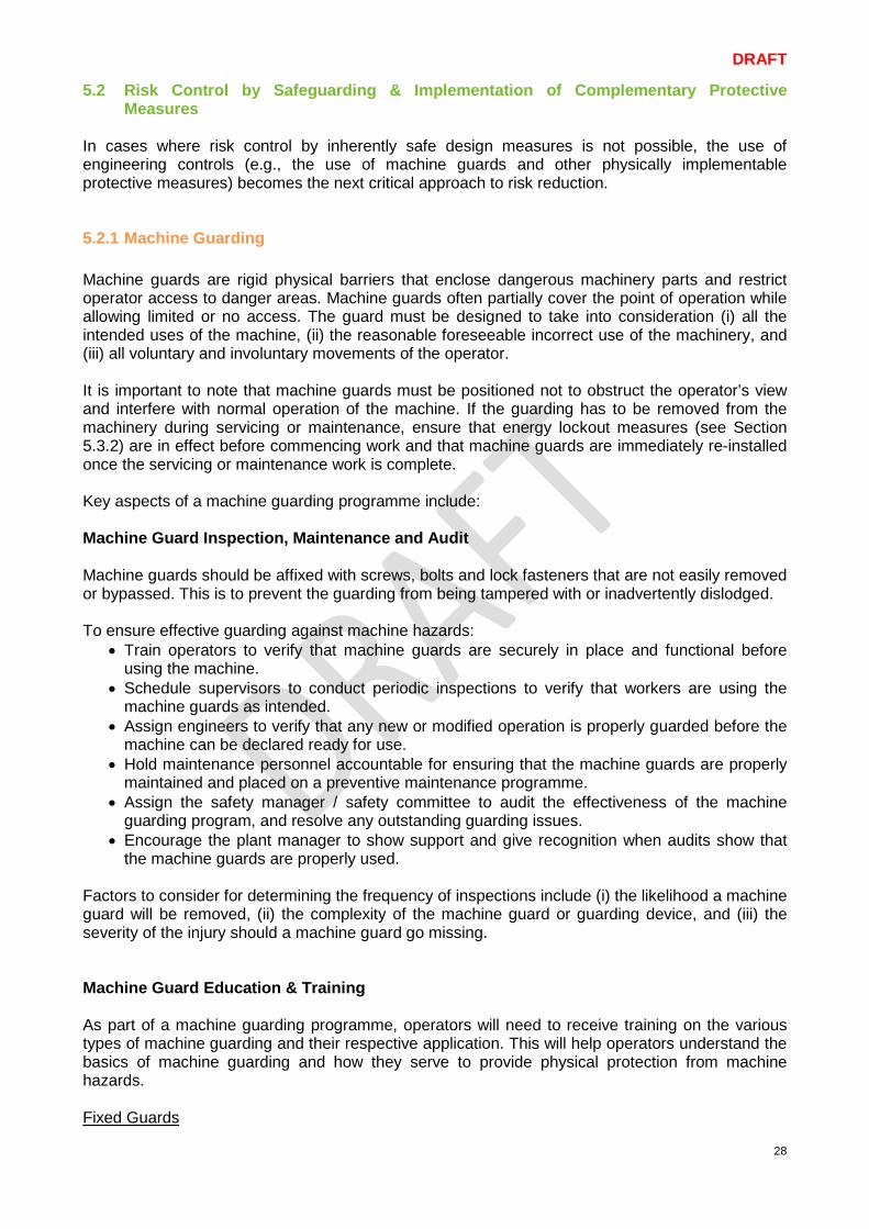
In cases where risk control by inherently safe design measures is not possible, the use of engineering controls (e.g., the use of machine guards and other physically implementable protective measures) becomes the next critical approach to risk reduction. 5.2.1 Machine Guarding Machine guards are rigid physical barriers that enclose dangerous machinery parts and restrict operator access to danger areas. Machine guards often partially cover the point of operation while allowing limited or no access. The guard must be designed to take into consideration (i) all the intended uses of the machine, (ii) the reasonable foreseeable incorrect use of the machinery, and (iii) all voluntary and involuntary movements of the operator. It is important to note that machine guards must be positioned not to obstruct the operator’s view and interfere with normal operation of the machine. If the guarding has to be removed from the machinery during servicing or maintenance, ensure that energy lockout measures (see Section 5.3.2) are in effect before commencing work and that machine guards are immediately re-installed once the servicing or maintenance work is complete. Key aspects of a machine guarding programme include: Machine Guard Inspection, Maintenance and Audit Machine guards should be affixed with screws, bolts and lock fasteners that are not easily removed or bypassed. This is to prevent the guarding from being tampered with or inadvertently dislodged. To ensure effective guarding against machine hazards:
• Train operators to verify that machine guards are securely in place and functional before using the machine.
• Schedule supervisors to conduct periodic inspections to verify that workers are using the machine guards as intended.
• Assign engineers to verify that any new or modified operation is properly guarded before the machine can be declared ready for use.
• Hold maintenance personnel accountable for ensuring that the machine guards are properly maintained and placed on a preventive maintenance programme.
• Assign the safety manager / safety committee to audit the effectiveness of the machine guarding program, and resolve any outstanding guarding issues.
• Encourage the plant manager to show support and give recognition when audits show that the machine guards are properly used.
Factors to consider for determining the frequency of inspections include (i) the likelihood a machine guard will be removed, (ii) the complexity of the machine guard or guarding device, and (iii) the severity of the injury should a machine guard go missing. Machine Guard Education & Training As part of a machine guarding programme, operators will need to receive training on the various types of machine guarding and their respective application. This will help operators understand the basics of machine guarding and how they serve to provide physical protection from machine hazards. Fixed Guards
DRAFT
29
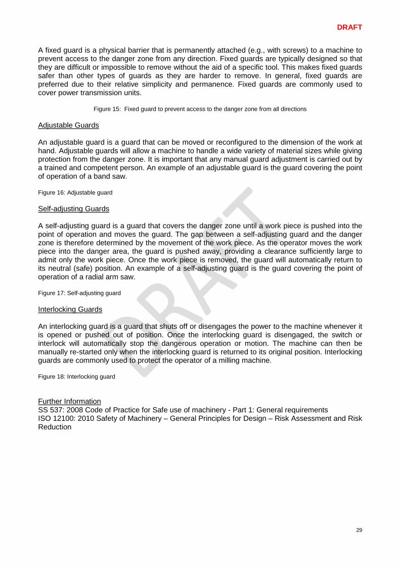
A fixed guard is a physical barrier that is permanently attached (e.g., with screws) to a machine to prevent access to the danger zone from any direction. Fixed guards are typically designed so that they are difficult or impossible to remove without the aid of a specific tool. This makes fixed guards safer than other types of guards as they are harder to remove. In general, fixed guards are preferred due to their relative simplicity and permanence. Fixed guards are commonly used to cover power transmission units.
Figure 15: Fixed guard to prevent access to the danger zone from all directions Adjustable Guards An adjustable guard is a guard that can be moved or reconfigured to the dimension of the work at hand. Adjustable guards will allow a machine to handle a wide variety of material sizes while giving protection from the danger zone. It is important that any manual guard adjustment is carried out by a trained and competent person. An example of an adjustable guard is the guard covering the point of operation of a band saw. Figure 16: Adjustable guard Self-adjusting Guards A self-adjusting guard is a guard that covers the danger zone until a work piece is pushed into the point of operation and moves the guard. The gap between a self-adjusting guard and the danger zone is therefore determined by the movement of the work piece. As the operator moves the work piece into the danger area, the guard is pushed away, providing a clearance sufficiently large to admit only the work piece. Once the work piece is removed, the guard will automatically return to its neutral (safe) position. An example of a self-adjusting guard is the guard covering the point of operation of a radial arm saw. Figure 17: Self-adjusting guard Interlocking Guards An interlocking guard is a guard that shuts off or disengages the power to the machine whenever it is opened or pushed out of position. Once the interlocking guard is disengaged, the switch or interlock will automatically stop the dangerous operation or motion. The machine can then be manually re-started only when the interlocking guard is returned to its original position. Interlocking guards are commonly used to protect the operator of a milling machine. Figure 18: Interlocking guard Further Information SS 537: 2008 Code of Practice for Safe use of machinery - Part 1: General requirements ISO 12100: 2010 Safety of Machinery – General Principles for Design – Risk Assessment and Risk Reduction
DRAFT
30
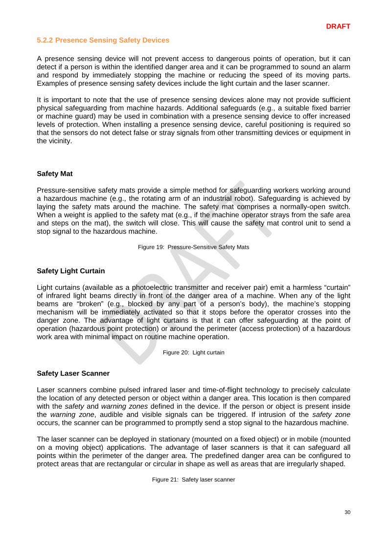
5.2.2 Presence Sensing Safety Devices A presence sensing device will not prevent access to dangerous points of operation, but it can detect if a person is within the identified danger area and it can be programmed to sound an alarm and respond by immediately stopping the machine or reducing the speed of its moving parts. Examples of presence sensing safety devices include the light curtain and the laser scanner. It is important to note that the use of presence sensing devices alone may not provide sufficient physical safeguarding from machine hazards. Additional safeguards (e.g., a suitable fixed barrier or machine guard) may be used in combination with a presence sensing device to offer increased levels of protection. When installing a presence sensing device, careful positioning is required so that the sensors do not detect false or stray signals from other transmitting devices or equipment in the vicinity. Safety Mat Pressure-sensitive safety mats provide a simple method for safeguarding workers working around a hazardous machine (e.g., the rotating arm of an industrial robot). Safeguarding is achieved by laying the safety mats around the machine. The safety mat comprises a normally-open switch. When a weight is applied to the safety mat (e.g., if the machine operator strays from the safe area and steps on the mat), the switch will close. This will cause the safety mat control unit to send a stop signal to the hazardous machine.
Figure 19: Pressure-Sensitive Safety Mats Safety Light Curtain Light curtains (available as a photoelectric transmitter and receiver pair) emit a harmless “curtain” of infrared light beams directly in front of the danger area of a machine. When any of the light beams are “broken” (e.g., blocked by any part of a person’s body), the machine’s stopping mechanism will be immediately activated so that it stops before the operator crosses into the danger zone. The advantage of light curtains is that it can offer safeguarding at the point of operation (hazardous point protection) or around the perimeter (access protection) of a hazardous work area with minimal impact on routine machine operation.
Figure 20: Light curtain
Safety Laser Scanner Laser scanners combine pulsed infrared laser and time-of-flight technology to precisely calculate the location of any detected person or object within a danger area. This location is then compared with the safety and warning zones defined in the device. If the person or object is present inside the warning zone, audible and visible signals can be triggered. If intrusion of the safety zone occurs, the scanner can be programmed to promptly send a stop signal to the hazardous machine. The laser scanner can be deployed in stationary (mounted on a fixed object) or in mobile (mounted on a moving object) applications. The advantage of laser scanners is that it can safeguard all points within the perimeter of the danger area. The predefined danger area can be configured to protect areas that are rectangular or circular in shape as well as areas that are irregularly shaped.
Figure 21: Safety laser scanner
DRAFT
31
Safety Camera Safety camera systems are electro-sensitive protective devices based on three-dimensional (3D) image processing technology. In contrast to simple sensors, a safety camera system is able to continuously monitor a danger area and record / analyse detailed information concerning the entire area being monitored. The detection zone of a safety camera is typically divided into warning and danger zones. If a person or object enters the warning zone, the system can be programmed to sound off the alarm and slow down the hazardous machine. Should the person or object approach the danger zone, the system would promptly trigger an emergency stop command to shut down the machine.
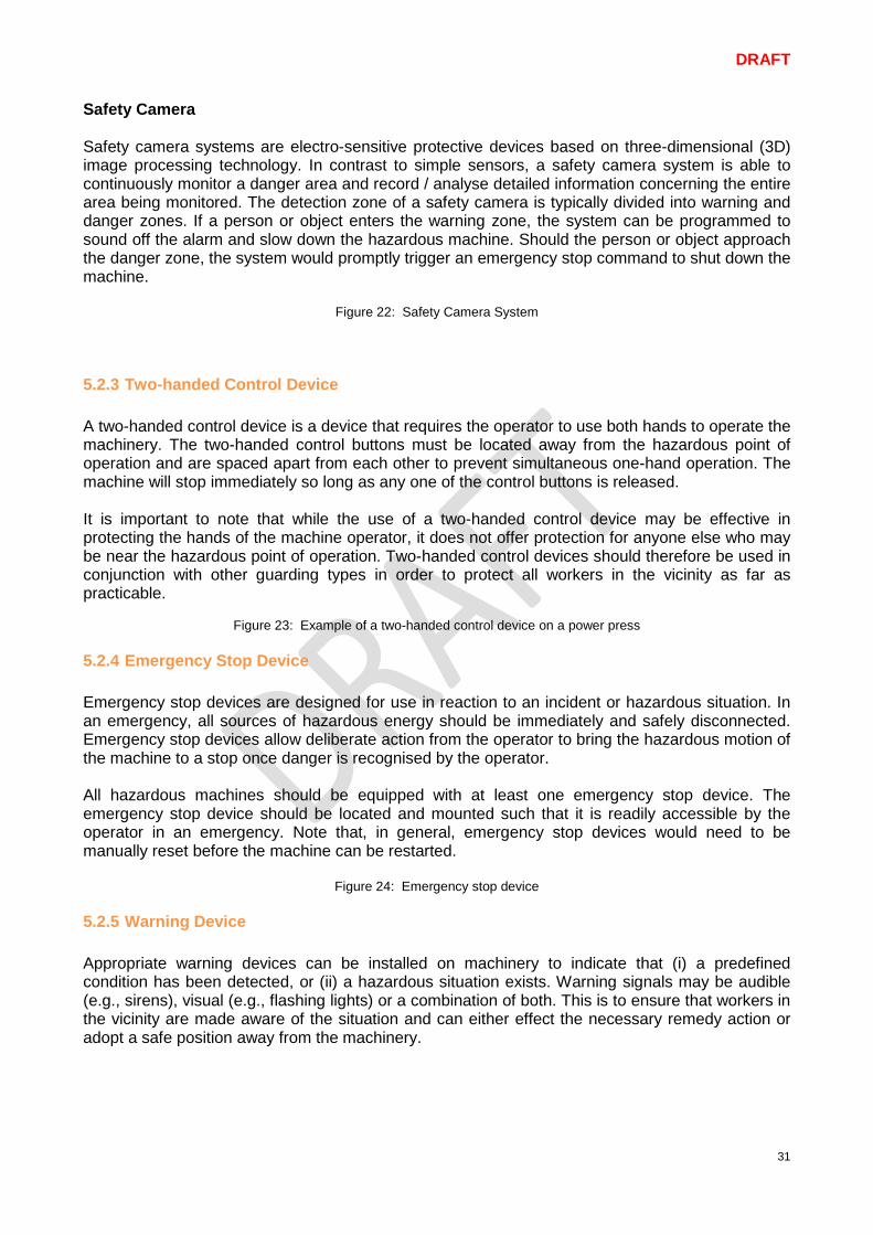
Figure 22: Safety Camera System 5.2.3 Two-handed Control Device A two-handed control device is a device that requires the operator to use both hands to operate the machinery. The two-handed control buttons must be located away from the hazardous point of operation and are spaced apart from each other to prevent simultaneous one-hand operation. The machine will stop immediately so long as any one of the control buttons is released. It is important to note that while the use of a two-handed control device may be effective in protecting the hands of the machine operator, it does not offer protection for anyone else who may be near the hazardous point of operation. Two-handed control devices should therefore be used in conjunction with other guarding types in order to protect all workers in the vicinity as far as practicable.
Figure 23: Example of a two-handed control device on a power press 5.2.4 Emergency Stop Device Emergency stop devices are designed for use in reaction to an incident or hazardous situation. In an emergency, all sources of hazardous energy should be immediately and safely disconnected. Emergency stop devices allow deliberate action from the operator to bring the hazardous motion of the machine to a stop once danger is recognised by the operator. All hazardous machines should be equipped with at least one emergency stop device. The emergency stop device should be located and mounted such that it is readily accessible by the operator in an emergency. Note that, in general, emergency stop devices would need to be manually reset before the machine can be restarted.
Figure 24: Emergency stop device 5.2.5 Warning Device Appropriate warning devices can be installed on machinery to indicate that (i) a predefined condition has been detected, or (ii) a hazardous situation exists. Warning signals may be audible (e.g., sirens), visual (e.g., flashing lights) or a combination of both. This is to ensure that workers in the vicinity are made aware of the situation and can either effect the necessary remedy action or adopt a safe position away from the machinery.
DRAFT
32
5.3 Risk Control by Information for Use If risk control by safeguarding and implementation of complementary protective measures is insufficient to bring the risk down to the desired safe level, further risk control can be achieved through the provision of information for use (e.g., via warning signs and safe work procedures). Such information will serve to alert machine operators of the residual risks and the administrative control measures put in place to keep the work activity safe. 5.3.1 Safe Work Procedures A Safe Work Procedure (SWP) is much more than a Standard Operating Procedure (SOP). A Safe Work Procedure is a working risk control document that describes the safest and most efficient way to perform a certain work activity. A SWP generally lists the hazards involved in performing a work activity, the personal protective equipment required, and the operating steps necessary to complete the activity without incident. A good SWP document should contain detailed information on the following:- • Hazards of the machinery, equipment and material being used • Inherent risks associated with the work activity • Operating steps / sequence of steps for safely carrying out the work activity • Risk control measures implemented including the personal protective equipment to be used • Residual risks and the action to be taken to address the residual risks while carrying out the
work activity Refer to Annex B for guidance on the establishment of a SWP. To ensure safe use of machinery, all operators must familiarize with the SWP and adhere closely to it at all times. Procedures should be kept clear and simple so that they are easy to understand and remember. SWP documents are most effective when developed in consultation with workers, and are a useful tool for workplace training and supervision. SWP documents will need to be reviewed if there is a workplace incident and especially when changes occur (e.g., when new machinery or processes are introduced) in the workplace.
DRAFT
33
5.3.2 Energy Lock-out Tag-out The Lock-out tag-out (LOTO) procedure is a set of procedures to ensure that all hazardous energy sources (whether electrical, mechanical, pneumatic or hydraulic) to the relevant machinery are isolated, disconnected or discharged prior to commencing work for activities like maintenance, repair, and installation of machinery. This is to prevent any machine from being inadvertently activated or energised while the work activity is in progress. Below are five recommended steps for the effective lock-out and tag-out of hazardous machinery:
1) Announce the shutdown Notify all affected workers that the machinery is to be shut down.
2) Shut down the machinery
Proceed to shut down the machinery via normal shutdown procedure.
3) Disconnect all energy sources Disconnect all sources of hazardous energy (whether electrical, mechanical, pneumatic or hydraulic) supply to the machinery. Energy-isolating devices such as manually operated circuit breakers or isolating switches / valves are commonly used for disconnecting energy sources. Confirm that any stored energy (e.g., found in springs, electrical, hydraulic and pneumatic systems) is dissipated before starting work.
4) Apply lock-out and tagout
Apply a lock-out device (e.g., a padlock) over each energy-isolating device to ensure that all hazardous energy sources cannot be restored unexpectedly or accidentally. Lock-out devices must be durable and strong enough to prevent accidental removal. Each lock-out device should be affixed with a durable tag to indicate the identity of the person applying the lock-out. The tag serves to warn that a work activity involving the machine is in progress and that it must not be turned on under any circumstances. Do not use a tag on its own as it is not an energy isolation device.
5) Verify the isolation and lock-out Check that the isolation and lock-out is in force and effective. Test the operating controls by putting (or trying to put) the controls in the "ON" position to confirm that the machinery is unable to start up. Return operating controls to the "OFF" position.
Once the above steps are completed, it is now safe to proceed with the installation, repair or maintenance work on the machinery. Group Lock-out In cases where there are workers working on different parts of a large machine, a lock-out hasp (typically with six padlock holes) may be used to allow each worker to affix his / her own lock-out device to the energy-isolating device. If a larger number of workers are involved, a coordinator may be appointed to coordinate the work. A group lock box may be used to facilitate coordination. Once all energy sources have been isolated, stored energy released and locked out, all keys are placed into the group lock box. The coordinator then applies his personal lock on the group lock box. This is to ensure that no one can remove the locks on any energy-isolating device until all workers have finished working on the locked-out machinery.

DRAFT
34
Lock-out devices should be removed only after the machine is fully assembled / re-assembled and all affected workers notified. To ensure that each worker working on the machine is safe and accounted for, it is critical for each lock-out device to be removed by the same person who applied it on the machine. Continuity of Lock-out To ensure continued protection of workers during change of personnel (e.g., during shift change), both the outgoing worker and the incoming worker should be present at the same time to remove the existing lock-out device and apply the new lock-out device respectively. To guarantee that the lock-out is in force at all times, recommended practice is for the outgoing worker to remove the existing lock-out device only after the incoming worker has successfully applied the new lock-out device. Note that the transfer of lock-out device could also take the form of a transfer of the key of the lock-out device. Further Information SS 571: 2011 Code of Practice for Energy Lockout and Tagout
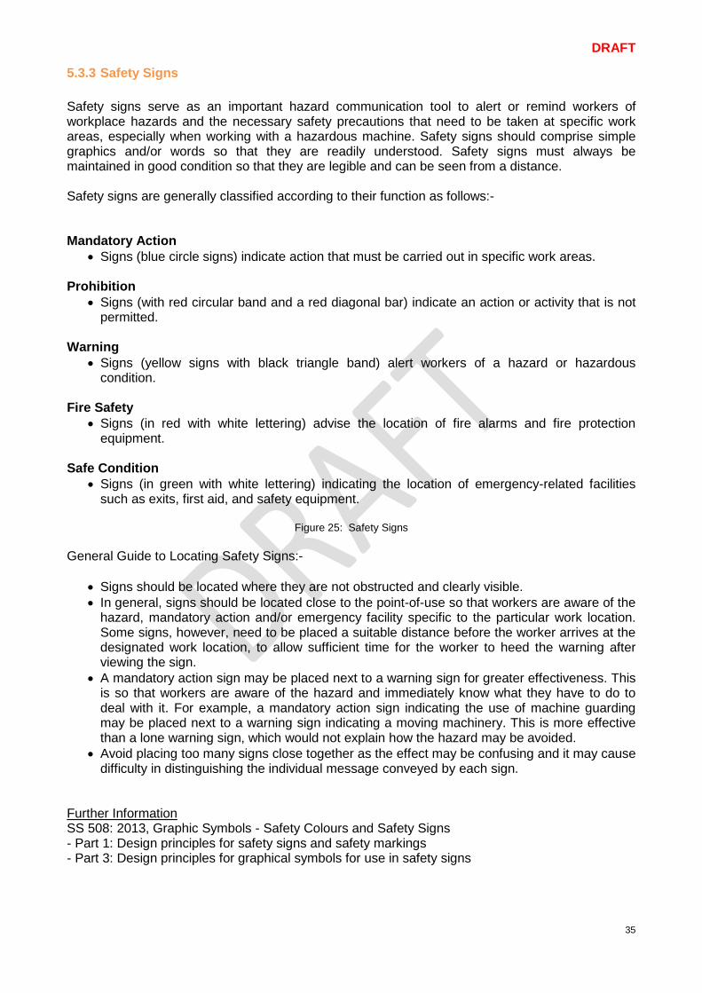
DRAFT
35
5.3.3 Safety Signs Safety signs serve as an important hazard communication tool to alert or remind workers of workplace hazards and the necessary safety precautions that need to be taken at specific work areas, especially when working with a hazardous machine. Safety signs should comprise simple graphics and/or words so that they are readily understood. Safety signs must always be maintained in good condition so that they are legible and can be seen from a distance. Safety signs are generally classified according to their function as follows:- Mandatory Action
• Signs (blue circle signs) indicate action that must be carried out in specific work areas. Prohibition
• Signs (with red circular band and a red diagonal bar) indicate an action or activity that is not permitted.
Warning
• Signs (yellow signs with black triangle band) alert workers of a hazard or hazardous condition.
Fire Safety
• Signs (in red with white lettering) advise the location of fire alarms and fire protection equipment.
Safe Condition
• Signs (in green with white lettering) indicating the location of emergency-related facilities such as exits, first aid, and safety equipment.
Figure 25: Safety Signs
General Guide to Locating Safety Signs:-
• Signs should be located where they are not obstructed and clearly visible. • In general, signs should be located close to the point-of-use so that workers are aware of the
hazard, mandatory action and/or emergency facility specific to the particular work location. Some signs, however, need to be placed a suitable distance before the worker arrives at the designated work location, to allow sufficient time for the worker to heed the warning after viewing the sign.
• A mandatory action sign may be placed next to a warning sign for greater effectiveness. This is so that workers are aware of the hazard and immediately know what they have to do to deal with it. For example, a mandatory action sign indicating the use of machine guarding may be placed next to a warning sign indicating a moving machinery. This is more effective than a lone warning sign, which would not explain how the hazard may be avoided.
• Avoid placing too many signs close together as the effect may be confusing and it may cause difficulty in distinguishing the individual message conveyed by each sign.
Further Information SS 508: 2013, Graphic Symbols - Safety Colours and Safety Signs - Part 1: Design principles for safety signs and safety markings - Part 3: Design principles for graphical symbols for use in safety signs
DRAFT
36
5.3.4 Personal Protective Equipment (PPE) Personal Protective Equipment (PPE) includes items of protective clothing such as overalls, covered non-slip shoes, heat-resistant gloves, and protective items such as safety eyewear and the use of respirators. PPE offers protection from workplace hazards only if it is in good condition, properly selected for the work activity and correctly-fitted to the user. Workers may be exposed to falling or flying objects, to splashing fluids, or to harmful dusts, fumes, mists, vapours, or gases when working with a machine. It is therefore important to provide workers with suitable PPE and the information necessary for correct use to ensure effective protection from the hazards present at the workplace. As the use of PPE does not eliminate or reduce the hazard, the PPE user is likely to be exposed to the hazard should the PPE fail. Given that PPE should be considered as the last level of protection when all other control measures are not feasible, a PPE programme is recommended to ensure that workers are indeed protected when PPE is used. Key elements of a comprehensive PPE programme include:
• PPE selection • PPE fitting • PPE maintenance & storage • PPE user education & training
PPE Selection All activities involving the use of machinery shall be thoroughly evaluated by risk assessment so that suitable PPE can be selected specifically for each activity. Once the hazards have been identified, a useful approach is to think through from “head-to-toe” on the protection needed to prevent worker injury. PPE Fitting For effective protection, PPE will need to be correctly fitted to its user e.g., safety shoes, custom-fit overalls, etc. PPE Maintenance & Storage To keep PPE in good condition and ready for use, it needs to be properly stored to prevent material deterioration. PPE should also be subjected to regular maintenance and checks before use. Finally, it is important for PPE to be replaced periodically, depending on the frequency of use, and lifespan of its material. PPE User Education & Training As part of a comprehensive PPE programme, users will need to receive training on the proper selection of PPE, choice of appropriate material and the correct method for its use.
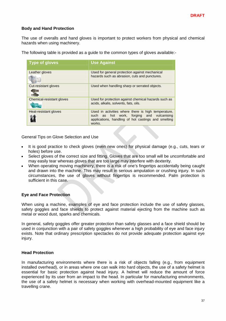
DRAFT
37
Body and Hand Protection The use of overalls and hand gloves is important to protect workers from physical and chemical hazards when using machinery. The following table is provided as a guide to the common types of gloves available:-
Type of gloves Use Against
Leather gloves
Used for general protection against mechanical hazards such as abrasion, cuts and punctures.
Cut-resistant gloves
Used when handling sharp or serrated objects.
Chemical-resistant gloves
Used for protection against chemical hazards such as acids, alkalis, solvents, fats, oils.
Heat-resistant gloves
Used in activities where there is high temperature, such as hot work, forging and vulcanising applications, handling of hot castings and smelting works.
General Tips on Glove Selection and Use • It is good practice to check gloves (even new ones) for physical damage (e.g., cuts, tears or
holes) before use. • Select gloves of the correct size and fitting. Gloves that are too small will be uncomfortable and
may easily tear whereas gloves that are too large may interfere with dexterity. • When operating moving machinery, there is a risk of one’s fingertips accidentally being caught
and drawn into the machine. This may result in serious amputation or crushing injury. In such circumstances, the use of gloves without fingertips is recommended. Palm protection is sufficient in this case.
Eye and Face Protection When using a machine, examples of eye and face protection include the use of safety glasses, safety goggles and face shields to protect against material ejecting from the machine such as metal or wood dust, sparks and chemicals. In general, safety goggles offer greater protection than safety glasses and a face shield should be used in conjunction with a pair of safety goggles whenever a high probability of eye and face injury exists. Note that ordinary prescription spectacles do not provide adequate protection against eye injury. Head Protection In manufacturing environments where there is a risk of objects falling (e.g., from equipment installed overhead), or in areas where one can walk into hard objects, the use of a safety helmet is essential for basic protection against head injury. A helmet will reduce the amount of force experienced by its user from an impact to the head. In particular for manufacturing environments, the use of a safety helmet is necessary when working with overhead-mounted equipment like a travelling crane.
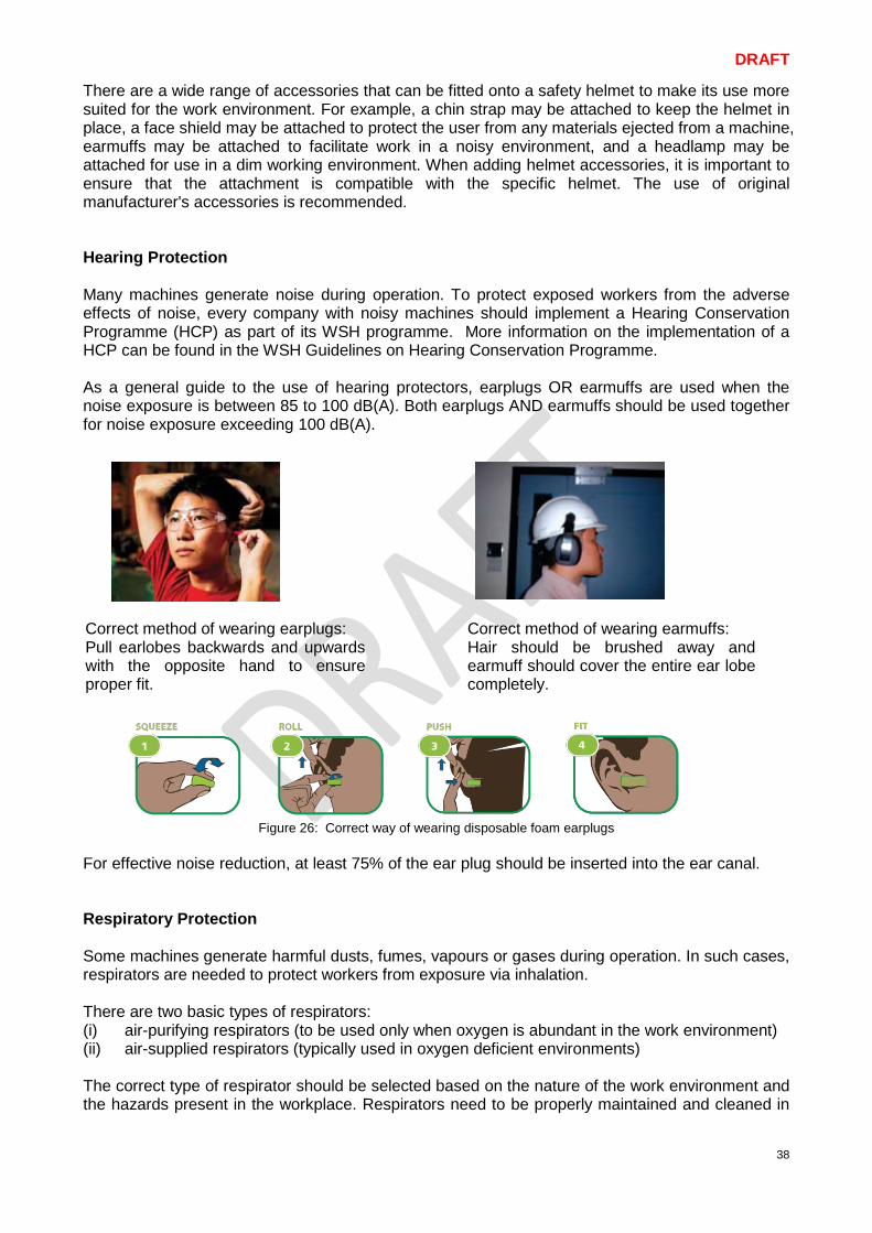
DRAFT
38
There are a wide range of accessories that can be fitted onto a safety helmet to make its use more suited for the work environment. For example, a chin strap may be attached to keep the helmet in place, a face shield may be attached to protect the user from any materials ejected from a machine, earmuffs may be attached to facilitate work in a noisy environment, and a headlamp may be attached for use in a dim working environment. When adding helmet accessories, it is important to ensure that the attachment is compatible with the specific helmet. The use of original manufacturer's accessories is recommended. Hearing Protection Many machines generate noise during operation. To protect exposed workers from the adverse effects of noise, every company with noisy machines should implement a Hearing Conservation Programme (HCP) as part of its WSH programme. More information on the implementation of a HCP can be found in the WSH Guidelines on Hearing Conservation Programme. As a general guide to the use of hearing protectors, earplugs OR earmuffs are used when the noise exposure is between 85 to 100 dB(A). Both earplugs AND earmuffs should be used together for noise exposure exceeding 100 dB(A).
Figure 26: Correct way of wearing disposable foam earplugs For effective noise reduction, at least 75% of the ear plug should be inserted into the ear canal. Respiratory Protection Some machines generate harmful dusts, fumes, vapours or gases during operation. In such cases, respirators are needed to protect workers from exposure via inhalation. There are two basic types of respirators: (i) air-purifying respirators (to be used only when oxygen is abundant in the work environment) (ii) air-supplied respirators (typically used in oxygen deficient environments) The correct type of respirator should be selected based on the nature of the work environment and the hazards present in the workplace. Respirators need to be properly maintained and cleaned in
Correct method of wearing earplugs: Pull earlobes backwards and upwards with the opposite hand to ensure proper fit.
Correct method of wearing earmuffs: Hair should be brushed away and earmuff should cover the entire ear lobe completely.
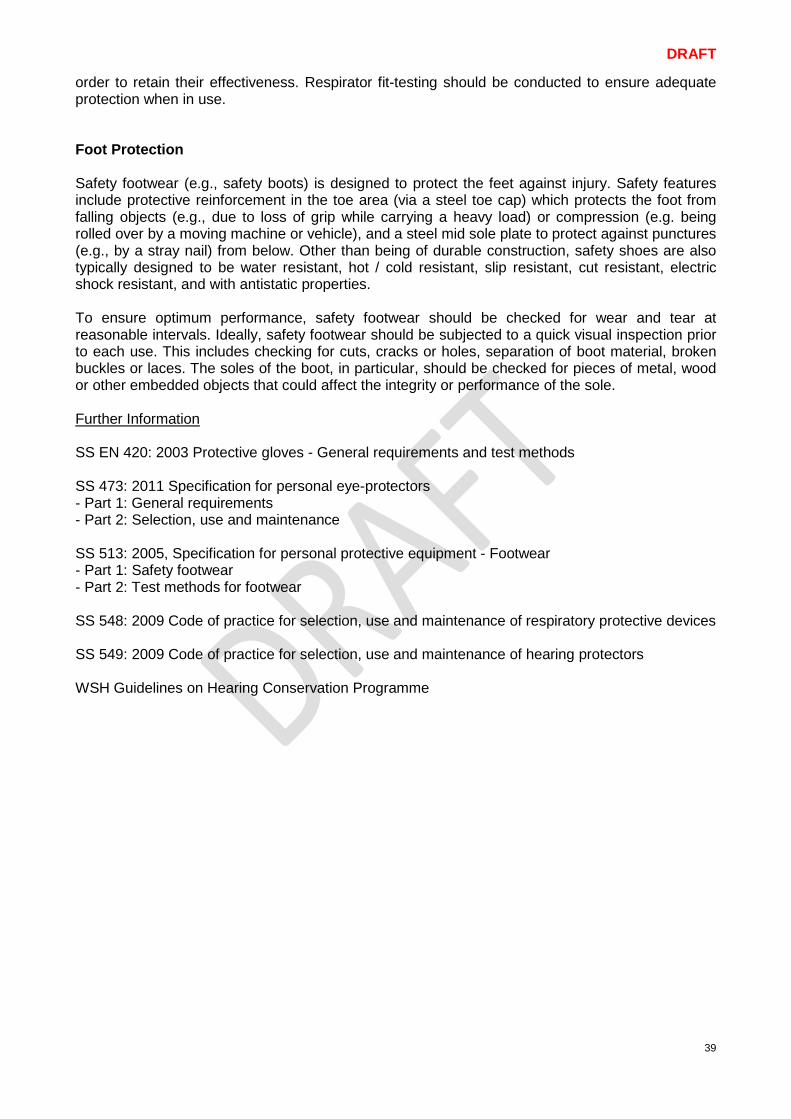
DRAFT
39
order to retain their effectiveness. Respirator fit-testing should be conducted to ensure adequate protection when in use. Foot Protection Safety footwear (e.g., safety boots) is designed to protect the feet against injury. Safety features include protective reinforcement in the toe area (via a steel toe cap) which protects the foot from falling objects (e.g., due to loss of grip while carrying a heavy load) or compression (e.g. being rolled over by a moving machine or vehicle), and a steel mid sole plate to protect against punctures (e.g., by a stray nail) from below. Other than being of durable construction, safety shoes are also typically designed to be water resistant, hot / cold resistant, slip resistant, cut resistant, electric shock resistant, and with antistatic properties. To ensure optimum performance, safety footwear should be checked for wear and tear at reasonable intervals. Ideally, safety footwear should be subjected to a quick visual inspection prior to each use. This includes checking for cuts, cracks or holes, separation of boot material, broken buckles or laces. The soles of the boot, in particular, should be checked for pieces of metal, wood or other embedded objects that could affect the integrity or performance of the sole. Further Information SS EN 420: 2003 Protective gloves - General requirements and test methods SS 473: 2011 Specification for personal eye-protectors - Part 1: General requirements - Part 2: Selection, use and maintenance SS 513: 2005, Specification for personal protective equipment - Footwear - Part 1: Safety footwear - Part 2: Test methods for footwear SS 548: 2009 Code of practice for selection, use and maintenance of respiratory protective devices SS 549: 2009 Code of practice for selection, use and maintenance of hearing protectors WSH Guidelines on Hearing Conservation Programme
DRAFT
40
6 Case Study 6.1 Case Study 1: Worker’s Palm Amputated by Power Press A production operator’s left palm was amputated by the descending tool of an 80-ton power press in a metalworking factory while retrieving a stamped work piece from the power press. Observation and Findings
• The power press was not provided with any machine guard such as a fixed guard. • The power press was operating in a single-button activated control mode instead of two-hand
activated control. Lessons Learnt Risk Assessment Risk assessment must be carried out prior to any work involving the
power press. Safe Work Procedure Safe work procedures for the specific work activity involving the power
press must be developed and implemented. Equipment and Tools A suitable fixed guard and/or presence sensing device needs to be
installed to prevent the operator’s hands from straying into the danger zones of the power press. Correct mode of operation for the power press should be two-hand activation control.
Others (Process design, etc.)
There should be a regular maintenance and inspection programme to ensure that the machine and its safety devices are functioning properly at all times.
6.2 Case Study 2: Worker’s Palm Crushed by Food Cutting Machine An operator’s right palm was crushed by the shaft cutters of an electric food cutting machine in a food processing factory. He was hosing water down the shaft cutters to dislodge the food stuck at the rotating cutters when his right hand was suddenly pulled in and crushed by the rotating cutters. Observation and Findings The 31cm-by-17cm mouth of the rotating shaft cutters of the food cutting machine was not guarded to prevent the operator’s hands from coming into contact with the danger zone. Lessons Learnt Risk Assessment Risk assessment must be carried out prior to any work involving the
food cutting machine. Safe Work Procedure Safe work procedures for the specific work activity involving the food
cutting machine must be developed and implemented. Energy lock-out procedures should be carried out before cleaning machine.
Equipment and Tools A suitable fixed guard or presence sensing device needs to be installed to prevent the operator’s hands from entering the danger zone of the food cutting machine. Provide workers with a plunger of suitable length for reaching into the cutter area during cleaning operation.

DRAFT
41
Training and Awareness Workers should be trained on the energy lock-out procedures. Train new workers under the direct supervision of an experienced worker. Use warning and mandatory action signs to alert and remind operators of the machine’s danger zone.
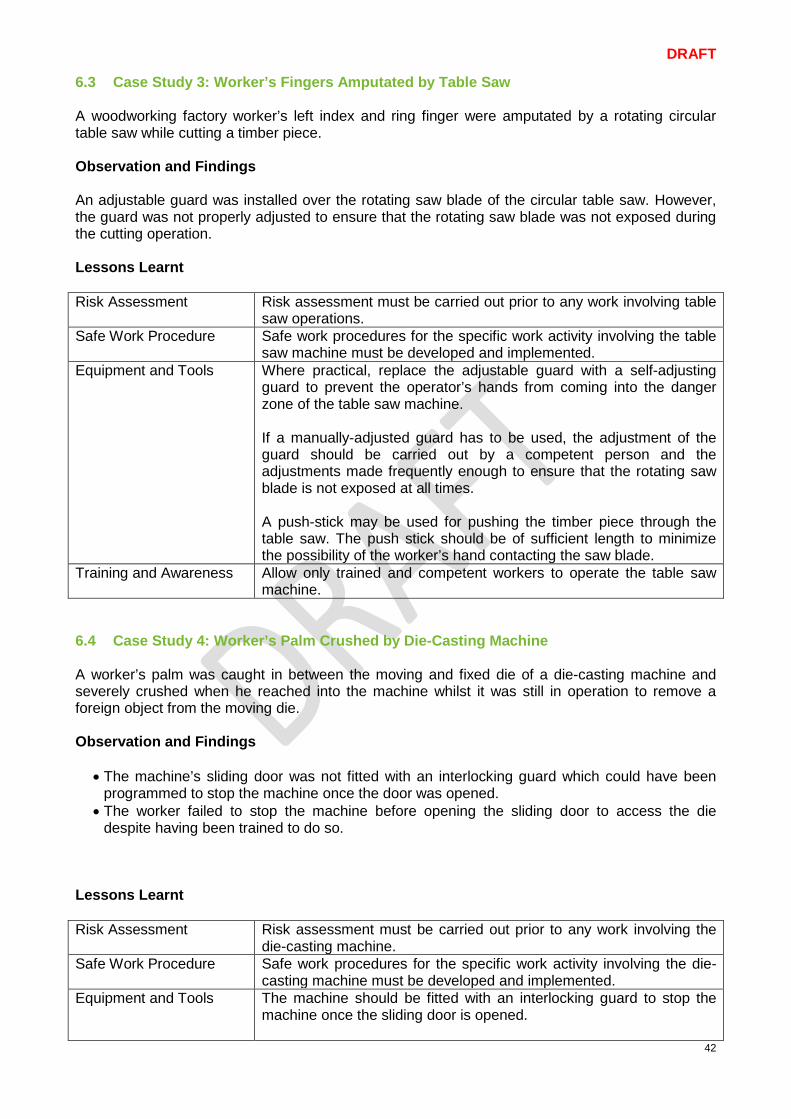
DRAFT
42
6.3 Case Study 3: Worker’s Fingers Amputated by Table Saw A woodworking factory worker’s left index and ring finger were amputated by a rotating circular table saw while cutting a timber piece. Observation and Findings An adjustable guard was installed over the rotating saw blade of the circular table saw. However, the guard was not properly adjusted to ensure that the rotating saw blade was not exposed during the cutting operation. Lessons Learnt Risk Assessment Risk assessment must be carried out prior to any work involving table
saw operations. Safe Work Procedure Safe work procedures for the specific work activity involving the table
saw machine must be developed and implemented. Equipment and Tools Where practical, replace the adjustable guard with a self-adjusting
guard to prevent the operator’s hands from coming into the danger zone of the table saw machine. If a manually-adjusted guard has to be used, the adjustment of the guard should be carried out by a competent person and the adjustments made frequently enough to ensure that the rotating saw blade is not exposed at all times. A push-stick may be used for pushing the timber piece through the table saw. The push stick should be of sufficient length to minimize the possibility of the worker’s hand contacting the saw blade.
Training and Awareness Allow only trained and competent workers to operate the table saw machine.
6.4 Case Study 4: Worker’s Palm Crushed by Die-Casting Machine A worker’s palm was caught in between the moving and fixed die of a die-casting machine and severely crushed when he reached into the machine whilst it was still in operation to remove a foreign object from the moving die. Observation and Findings
• The machine’s sliding door was not fitted with an interlocking guard which could have been programmed to stop the machine once the door was opened.
• The worker failed to stop the machine before opening the sliding door to access the die despite having been trained to do so.
Lessons Learnt Risk Assessment Risk assessment must be carried out prior to any work involving the
die-casting machine. Safe Work Procedure Safe work procedures for the specific work activity involving the die-
casting machine must be developed and implemented. Equipment and Tools The machine should be fitted with an interlocking guard to stop the
machine once the sliding door is opened.

DRAFT
43
Preventive maintenance of the interlocking device is important to ensure that it remains operational at all times.
Others (Process design, etc.)
Operators must be advised on the importance of stopping the die-casting machine before accessing its danger zone.
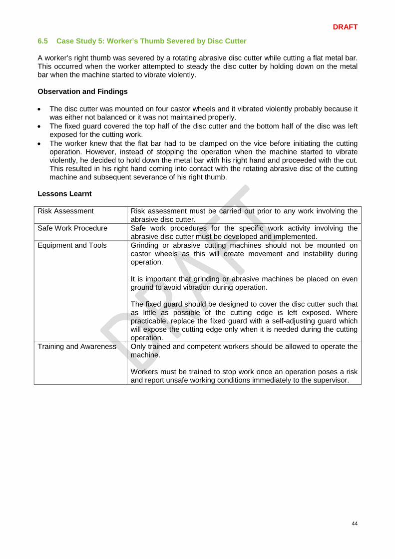
DRAFT
44
6.5 Case Study 5: Worker’s Thumb Severed by Disc Cutter A worker’s right thumb was severed by a rotating abrasive disc cutter while cutting a flat metal bar. This occurred when the worker attempted to steady the disc cutter by holding down on the metal bar when the machine started to vibrate violently. Observation and Findings • The disc cutter was mounted on four castor wheels and it vibrated violently probably because it
was either not balanced or it was not maintained properly. • The fixed guard covered the top half of the disc cutter and the bottom half of the disc was left
exposed for the cutting work. • The worker knew that the flat bar had to be clamped on the vice before initiating the cutting
operation. However, instead of stopping the operation when the machine started to vibrate violently, he decided to hold down the metal bar with his right hand and proceeded with the cut. This resulted in his right hand coming into contact with the rotating abrasive disc of the cutting machine and subsequent severance of his right thumb.
Lessons Learnt Risk Assessment Risk assessment must be carried out prior to any work involving the
abrasive disc cutter. Safe Work Procedure Safe work procedures for the specific work activity involving the
abrasive disc cutter must be developed and implemented. Equipment and Tools Grinding or abrasive cutting machines should not be mounted on
castor wheels as this will create movement and instability during operation. It is important that grinding or abrasive machines be placed on even ground to avoid vibration during operation. The fixed guard should be designed to cover the disc cutter such that as little as possible of the cutting edge is left exposed. Where practicable, replace the fixed guard with a self-adjusting guard which will expose the cutting edge only when it is needed during the cutting operation.
Training and Awareness Only trained and competent workers should be allowed to operate the machine. Workers must be trained to stop work once an operation poses a risk and report unsafe working conditions immediately to the supervisor.
DRAFT
45
7 Annex Annex 1- Sample WSH Checklist for Acquisition of Machinery
Description Yes No Basic Checks for Acquiring New Machinery Has a background check on the specific model been conducted to ascertain if there are existing WSH concerns?
Are inherently safe design measures included in the design of the machine? • Sharp edges, corners and protruding parts have been avoided
in the design; • Crush points, shear points and entanglement points have been
eliminated in the design; • Machine actuating force has been limited; • Machine has been designed to eliminate the need for
protective measures; • Machine ergonomics has been considered; • Highly hazardous machine operations have been automated; • High reliability machine components have been used.
Is the Declaration of Conformity provided by the machine manufacturer/ supplier? Are the risk assessment documents provided by the machine manufacturer/ supplier?
Is the machine operating manual provided? • Instructions for safe machine use • Instructions for safe assembly • Instructions for safe installation • Instructions for safe commissioning • Instructions for safe repair • Instructions for safe maintenance
Are detailed technical drawings of the machine provided? Is information on machine residual risks and the safety precautions
required provided in a document? Are the machine certified safety marks present as required by my
company? Can the machine manufacturer/ supplier provide machine-specific
and safety and health training for workers? Does the machine manufacturer/ supplier offer a servicing and
maintenance contract on its machines? Additional Checks for Acquiring Used Machinery
Are machine safeguards and safety devices present and functioning? Are the equipment warning signs clearly visible and easy to understand? Is the original manufacturer of the machine still in business? Are spare parts still available for the machine?
Is the machine manufacturer/ supplier able to carry out a pre-operational functionality test for each machine safety feature?
Have modified or retrofitted machines been certified safe for use?
DRAFT
46
Annex 2- Sample WSH Checklist for Installation of Machinery
Description Yes No Basic Checks for Installing a Machine
Is the on-site assembly work and installation performed by the machine manufacturer, authorised agent or competent person*? Is risk assessment conducted prior to the installation of the machine?
Is sufficient space allocated for unloading of the machine and its components?
Is sufficient space allocated for temporary storage of the machine and its components?
Is the machine installed in a location that does not obstruct the following: • Firefighting equipment; • Emergency escape routes; • Fire exits; • Building access route for firefighting operations.
Is sufficient space allocated for workers to work safely around the machine?
Is sufficient space allocated for safe passage past or through a group of machines?
Are machines with moving parts located at a safe distance from fixed structures?
Is the debris or waste material generated from the machine unpacking and installation process properly disposed of?
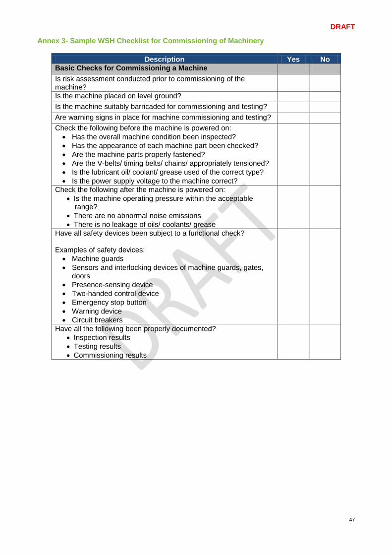
DRAFT
47
Annex 3- Sample WSH Checklist for Commissioning of Machinery
Description Yes No Basic Checks for Commissioning a Machine
Is risk assessment conducted prior to commissioning of the machine? Is the machine placed on level ground?
Is the machine suitably barricaded for commissioning and testing? Are warning signs in place for machine commissioning and testing? Check the following before the machine is powered on:
• Has the overall machine condition been inspected? • Has the appearance of each machine part been checked? • Are the machine parts properly fastened? • Are the V-belts/ timing belts/ chains/ appropriately tensioned? • Is the lubricant oil/ coolant/ grease used of the correct type? • Is the power supply voltage to the machine correct?
Check the following after the machine is powered on: • Is the machine operating pressure within the acceptable
range? • There are no abnormal noise emissions • There is no leakage of oils/ coolants/ grease
Have all safety devices been subject to a functional check? Examples of safety devices: • Machine guards • Sensors and interlocking devices of machine guards, gates,
doors • Presence-sensing device • Two-handed control device • Emergency stop button • Warning device • Circuit breakers
Have all the following been properly documented? • Inspection results • Testing results • Commissioning results
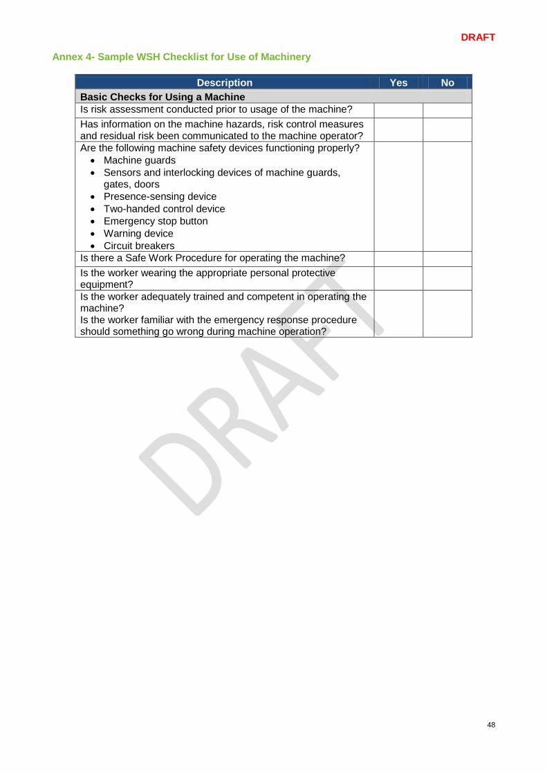
DRAFT
48
Annex 4- Sample WSH Checklist for Use of Machinery
Description Yes No Basic Checks for Using a Machine Is risk assessment conducted prior to usage of the machine? Has information on the machine hazards, risk control measures and residual risk been communicated to the machine operator?
Are the following machine safety devices functioning properly? • Machine guards • Sensors and interlocking devices of machine guards,
gates, doors • Presence-sensing device • Two-handed control device • Emergency stop button • Warning device • Circuit breakers
Is there a Safe Work Procedure for operating the machine? Is the worker wearing the appropriate personal protective
equipment? Is the worker adequately trained and competent in operating the
machine? Is the worker familiar with the emergency response procedure
should something go wrong during machine operation?

DRAFT
49
Annex 5- Sample WSH Checklist for Maintenance of Machinery
Description Yes No Basic Checks for Maintaining a Machine Is risk assessment conducted prior to maintenance of the machine? Is the person tasked to maintain/ diagnose the problem with the machine authorised and trained to carry out the maintenance?
Is the person carrying out the maintenance trained to: • recognise hazardous energy sources? • understand the magnitude of the energy source at hand? • identify and properly operate the applicable energy-isolating
devices? • carry out the lock-out and tag-out (LOTO) procedure? • safely apply and remove lock-out devices?
Are machine operators at the work site trained to: • understand the purpose of energy lock-out? • recognise when lock-out activities are in progress? • refrain from tampering with lock-out devices?
Are replacement parts and devices supplied or recommended by the manufacturer used for the maintenance?
Basic Checks for Restoring a Machine Have all maintenance equipment and tools been removed from the machine?
Are all machine safeguards and other safety devices reinstalled and functioning?
Has the immediate vicinity of the machine been checked to ensure no one will be endangered by the machine start-up?
Has a pre-operational functionality check been carried out before the machine is restored to full operation?
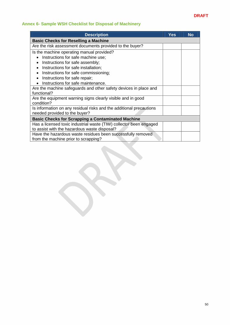
DRAFT
50
Annex 6- Sample WSH Checklist for Disposal of Machinery
Description Yes No Basic Checks for Reselling a Machine Are the risk assessment documents provided to the buyer?
Is the machine operating manual provided? • Instructions for safe machine use; • Instructions for safe assembly; • Instructions for safe installation; • Instructions for safe commissioning; • Instructions for safe repair; • Instructions for safe maintenance.
Are the machine safeguards and other safety devices in place and functional?
Are the equipment warning signs clearly visible and in good condition?
Is information on any residual risks and the additional precautions needed provided to the buyer?
Basic Checks for Scrapping a Contaminated Machine Has a licensed toxic industrial waste (TIW) collector been engaged to assist with the hazardous waste disposal? Have the hazardous waste residues been successfully removed from the machine prior to scrapping?
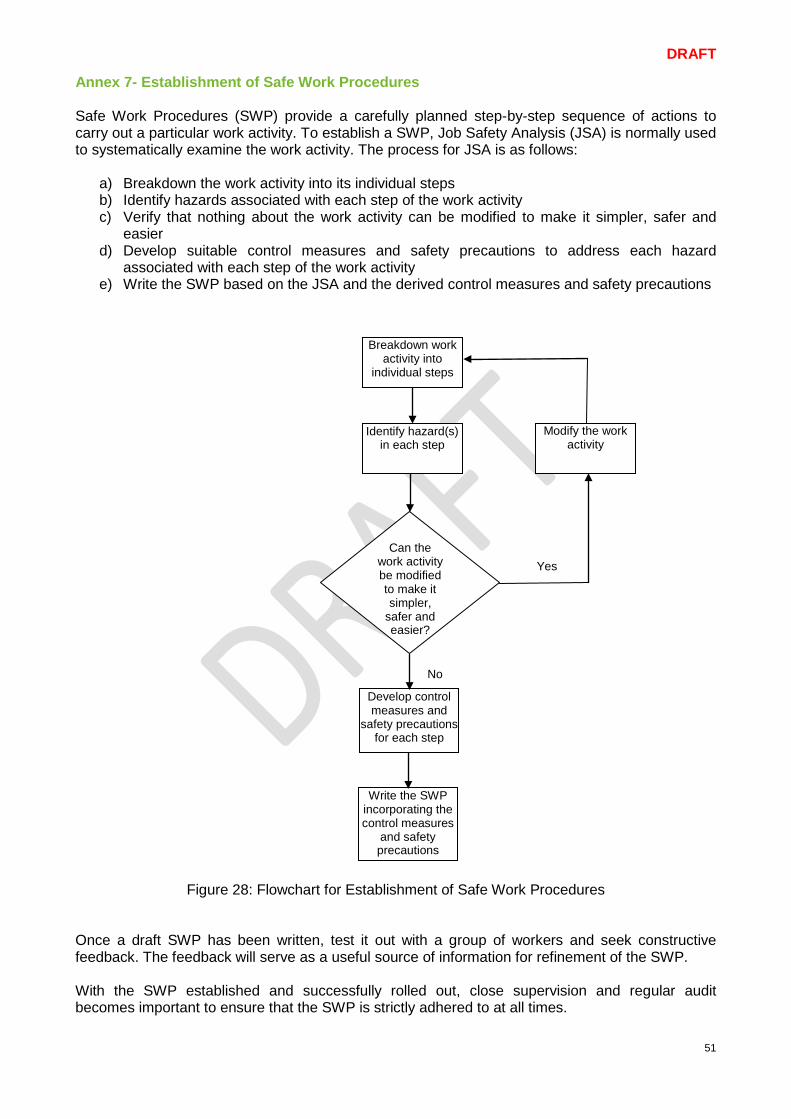
DRAFT
51
Annex 7- Establishment of Safe Work Procedures Safe Work Procedures (SWP) provide a carefully planned step-by-step sequence of actions to carry out a particular work activity. To establish a SWP, Job Safety Analysis (JSA) is normally used to systematically examine the work activity. The process for JSA is as follows:
a) Breakdown the work activity into its individual steps b) Identify hazards associated with each step of the work activity c) Verify that nothing about the work activity can be modified to make it simpler, safer and
easier d) Develop suitable control measures and safety precautions to address each hazard
associated with each step of the work activity e) Write the SWP based on the JSA and the derived control measures and safety precautions
Figure 28: Flowchart for Establishment of Safe Work Procedures Once a draft SWP has been written, test it out with a group of workers and seek constructive feedback. The feedback will serve as a useful source of information for refinement of the SWP. With the SWP established and successfully rolled out, close supervision and regular audit becomes important to ensure that the SWP is strictly adhered to at all times.
Breakdown work activity into
individual steps
Identify hazard(s) in each step
Develop control measures and
safety precautions for each step
Write the SWP incorporating the control measures
and safety precautions
Can the work activity be modified to make it simpler,
safer and easier?
Modify the work activity
Yes
No
DRAFT
52
8 References WSH Council Guidance Materials: • Code of Practice on WSH Risk Management • WSH Guidelines on Managing Safety and Health for SMEs in the Metalworking Industry • A Step-by-Step Guide on Risk Management for Metalworking Sector • WSH Guidelines on Hearing Conservation Programme • WSH Guidelines on Improving Ergonomics at the Workplace • WSH Guidelines on Fatigue Management • WSH Guidelines on Management of Hazardous Chemicals Programme • Case Studies for Metalworking Industry Singapore Regulations: Workplace Safety and Health Act and its subsidiary legislations: • WSH (Risk Management) Regulations • WSH (General Provisions) • WSH (Noise) • WSH (First-Aid) • WSH (Incident Reporting) Industry Standards: • SS 537: 2008 Code of Practice for Safe use of machinery- Part 1: General requirements • SS 567: 2011 Code of Practice for Factory layout- Safety, health and welfare considerations • SS 571: 2011 Code of Practice for Energy lockout and tagout • CP 100: 2004 Code of Practice for Hazardous waste management • SS 508: 2013 Graphic symbols – Safety Colours and safety signs-
Part 1: Design principles for safety signs and safety markings Part 3: Design principles for graphical symbols for use in safety signs
• SS EN 420: 2003 Protective gloves - General requirements and test methods • SS 473: 2011 Specification for personal eye-protectors
Part 1: General requirements Part 2: Selection, use and maintenance
• SS 513: 2005, Specification for personal protective equipment - Footwear Part 1: Safety footwear Part 2: Test methods for footwear
• SS 548: 2009 Code of practice for selection, use and maintenance of respiratory protective devices
• SS 549: 2009 Code of practice for selection, use and maintenance of hearing protectors • ISO 12100: 2010 Safety of Machinery- General Principles for Design- Risk Assessment and
Risk Reduction

DRAFT
53
9 Acknowledgement
The Institution of Engineers, Singapore Mr Tan Kai Hong Makino Asia Pte Ltd Mr Simon Yin Omron Asia Pacific Pte Ltd Mr Don Teng TϋV SϋD PSB Pte Ltd Mr Thomas Luo Workplace Safety and Health Council Mr Edison J Loh
Mr Terence Lim