Embed Size (px)
Citation preview
Proceedings of the ASME 2012 International Mechanical Engineering Congress & ExpositionIMECE2012
November 9-15, 2012, Houston, Texas, USA
IMECE2012-86987
DRAFT: THERMODYNAMIC ANALYSIS OF A REVERSE OSMOSIS DESALINATIONSYSTEM USING FORWARD OSMOSIS FOR ENERGY RECOVERY
Leonardo D. BanchikDepartment of Mechanical EngineeringMassachusetts Institute of Technology
Cambridge, MA 02139-4307 USAEmail: [email protected]
John H. Lienhard V∗Fellow of ASME
Department of Mechanical EngineeringMassachusetts Institute of Technology
Cambridge, MA 02139-4307 USAEmail: [email protected]
ABSTRACTThermodynamic analysis is applied to assess the energy effi-
ciency of hybrid desalination cycles that are driven by simultane-ous mixed inputs, including heat, electrical work, and chemicalenergy. A seawater desalination cycle using work and a chemicalinput stream is analyzed using seawater properties. Two systemmodels, a reversible separator and an irreversible componentbased model, are developed to find the least work required tooperate the system with and without osmotic recovery. The com-ponent based model represents a proposed desalination systemwhich uses a reverse osmosis membrane for solute separation,a pressure exchanger for recovering a fraction of the flow workassociated with the pressurized discharge brine, and a forwardosmosis (FO) module for recovering some of the chemical energycontained within the concentrated discharge brine. The energyattained by the addition of the chemical input stream serves tolower the amount of electrical work required for operation. Forthis analysis, a wastewater stream of varying solute concentra-tion, ranging from feed to brackish water salinity, is consideredas the chemical stream. Unlike other models available in theliterature, the FO exchanger is numerically simulated as a massexchanger of given size which accounts for changing stream con-centration, and consequently, stream-wise variations of osmoticpressure throughout the length of the unit. A parametric studyis performed on the models by varying input conditions. Forthe reversible case it is found that significant work reductionscan be made through the use of an energy recovery device when
∗Address all correspondence to this author.
the inlet wastewater salinity used is less than the feed salinity of35 g/kg. For the irreversible case with a typical recovery ratioand feed salinity, significant work reductions were only noted fora wastewater inlet of less than half of the feed salinity due topump work losses. In the irreversible case, the use of a numeri-cal model to simulate the FO exchanger resulted in a maximumwork reduction when the pressure difference between streamswas around one half of the osmotic pressure difference as op-posed to the precise value of one half found in zero-dimensionalexchanger models.
NOMENCLATURERoman symbols Unitsg specific Gibbs free energy kJ/kgh specific enthalpy kJ/kgm mass flow rate kg solution/sm∗ dimensionless mass flow rate ratio -P pressure barP∗ dimensionless pressure ratio -pr permeation ratio -Q heat transfer rate kWr recovery ratio -s specific entropy kJ/kg-KT temperature oCw salinity mass fraction g solute/kg solutionW work rate kW
Greek symbols Units
1 Copyright c© 2012 by ASME
π osmotic pressure barρ density kg solution/m3
Superscriptsrev reversible
Subscripts0 environmental propertyA system AB system Bb brine streamcomp compressiondb diluted brine streamexp expansionf feed streami the ith section of a one-dimensional exchangerleast reversible operationnet net system workp product streampump associated with a pumppure property of pure waterrec work recovered by use of energy recovery devicesep separationturb associated with a turbineww, in wastewater inlet streamww, out wastewater outlet stream
AcronymsERD energy recovery deviceFO forward osmosisppt parts per thousandPRO pressure-retarded osmosisPX pressure exchangerRO reverse osmosisTDS total dissolved solids
INTRODUCTIONAs fresh water resources are strained, the world is in-
creasingly turning to saline water sources to meet water de-mands. Both membrane and thermal technologies are commer-cially available for desalinating saline water sources, but a con-cern surrounding their implementation is the high energy costassociated with separation. As a result of a variety of technolog-ical improvements, such as the development of the pressure ex-changer and falling membrane costs, reverse osmosis (RO) sep-aration is currently the most widely used method for desalina-tion [1]. In an effort to make RO more viable, an energy recov-ery device (ERD) is proposed to reduce the amount of electricalwork required for operation.
All desalination systems discharge a concentrated brine witha higher salinity than the feed stream. By virtue of its composi-tion, the brine stream has a higher Gibbs free energy than the feedand can be used to recover chemical energy if it is not immedi-ately rejected to the environment. The proposed energy recoverydevice is a forward osmosis (FO) mass exchanger integrated witha pressure exchanger. The device can be used when a chemicalstream with a lower total dissolved solids (TDS) than the dis-charge brine is available. The chemical stream could be the feedstream water or another source such as wastewater. In certaincases, it may be more advantageous to simply purify and treat thewastewater source instead of desalinating the more saline stream.This study, however, assumes that the wastewater is only used torecover energy for the desalination process. This might representa case where policy does not allow for the human consumptionof treated wastewater.
Current literature in the area of FO is generally betweenstudies of desalination [2–6] and studies of power production[7–18]. Forward osmosis based power production is often re-ferred to as pressure-retarded osmosis (PRO) and it is currentlyreceiving significant attention in the literature.
This paper explores two perspectives of the ERD. First,we will use control volume thermodynamic analysis on two re-versible separators, one with and the other without energy recov-ery, in order to determine the theoretical least work required foroperation. Second, we use thermodynamic analysis to determinethe work required for a model of two systems with irreversiblecomponents. The first irreversible system is a single pass ROsystem with a pressure exchanger and the second is the sameplant integrated with an FO-based ERD.
For the reversible case it is found that significant work re-ductions can be made through the use of an ERD when the inletwastewater salinity used is lower than the feed salinity of 35 g/kg.For the irreversible case, early results suggested a wastewaterturbine is a necessary component for maximum work recovery.For the irreversible case with a recovery ratio of 0.4 and a feedsalinity of 35 g/kg, significant work reductions were only notedfor a wastewater inlet of less than 20 g/kg due to pump worklosses. In the irreversible case, the use of a numerical model tosimulate the FO exchanger resulted in a maximum work reduc-tion when the pressure difference between streams was aroundone half of the osmotic pressure difference as opposed to theprecise value of one half found in zero-dimensional exchangermodels [11, 13–15].
THERMODYNAMIC ANALYSIS OF REVERSIBLE SEPA-RATION
Two reversible separators are shown in Fig. 1. Both systemsrepresent black box processes that reversibly separate an incom-ing feed stream of saline water into a product stream of low salin-ity and a concentrated brine stream. The mass flow rates denoted
2 Copyright c© 2012 by ASME
Separator
Reversible Separator
𝑚 b
𝑊 𝑠𝑒𝑝 𝑚 p
𝑚 f
𝑇 = 𝑇𝑜
Feed
Product
Brine
𝑄
(a) System A
𝑚 db
𝑇 = 𝑇𝑜
𝑚 ww, in
Reversible Separator
𝑊 𝑠𝑒𝑝 𝑚 p
𝑚 f
Reversible Energy Recovery Device Diluted Brine
Waste Water
Feed
Product
𝑚 ww, out
𝑚 b Brine
𝑄
∆𝑚 ww
Separator with Energy Recovery (b) System B
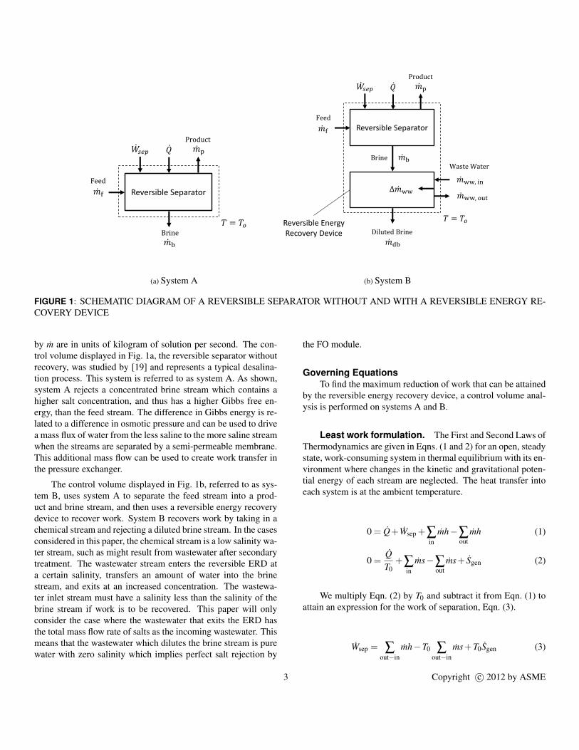
FIGURE 1: SCHEMATIC DIAGRAM OF A REVERSIBLE SEPARATOR WITHOUT AND WITH A REVERSIBLE ENERGY RE-COVERY DEVICE
by m are in units of kilogram of solution per second. The con-trol volume displayed in Fig. 1a, the reversible separator withoutrecovery, was studied by [19] and represents a typical desalina-tion process. This system is referred to as system A. As shown,system A rejects a concentrated brine stream which contains ahigher salt concentration, and thus has a higher Gibbs free en-ergy, than the feed stream. The difference in Gibbs energy is re-lated to a difference in osmotic pressure and can be used to drivea mass flux of water from the less saline to the more saline streamwhen the streams are separated by a semi-permeable membrane.This additional mass flow can be used to create work transfer inthe pressure exchanger.
The control volume displayed in Fig. 1b, referred to as sys-tem B, uses system A to separate the feed stream into a prod-uct and brine stream, and then uses a reversible energy recoverydevice to recover work. System B recovers work by taking in achemical stream and rejecting a diluted brine stream. In the casesconsidered in this paper, the chemical stream is a low salinity wa-ter stream, such as might result from wastewater after secondarytreatment. The wastewater stream enters the reversible ERD ata certain salinity, transfers an amount of water into the brinestream, and exits at an increased concentration. The wastewa-ter inlet stream must have a salinity less than the salinity of thebrine stream if work is to be recovered. This paper will onlyconsider the case where the wastewater that exits the ERD hasthe total mass flow rate of salts as the incoming wastewater. Thismeans that the wastewater which dilutes the brine stream is purewater with zero salinity which implies perfect salt rejection by
the FO module.
Governing EquationsTo find the maximum reduction of work that can be attained
by the reversible energy recovery device, a control volume anal-ysis is performed on systems A and B.
Least work formulation. The First and Second Laws ofThermodynamics are given in Eqns. (1 and 2) for an open, steadystate, work-consuming system in thermal equilibrium with its en-vironment where changes in the kinetic and gravitational poten-tial energy of each stream are neglected. The heat transfer intoeach system is at the ambient temperature.
0 = Q+Wsep +∑in
mh−∑out
mh (1)
0 =QT0
+∑in
ms−∑out
ms+ Sgen (2)
We multiply Eqn. (2) by T0 and subtract it from Eqn. (1) toattain an expression for the work of separation, Eqn. (3).
Wsep = ∑out−in
mh−T0 ∑out−in
ms+T0Sgen (3)
3 Copyright c© 2012 by ASME
For a reversible system, Sgen = 0, and Eqn. (3) becomesEqn. (4).
Wleast ≡ W revsep = ∑
out−inmh−T0 ∑
out−inms (4)
If we assume for simplicity that all streams entering and ex-iting the control volume are isothermal at the environment tem-perature, then the energy balance given in Eqn. (4) becomes aGibbs free energy (g≡ h−T s) balance as given in Eqn. (5).
Wleast = ∑out
mg−∑in
mg (5)
Conservation of mass. For both separator models,conservation of mass must be satisfied. Solution and salt bal-ances for system A are given in Eqns. (6 and 7). Here we definew as the mass fraction of salt in units of grams of solute per kilo-gram of solution (parts per thousand).
mf = mp + mb (6)mfwf = mpwp + mbwb (7)
Equations (6 and 7) still apply for system B along withadditional balance expressions for the streams interacting withthe control volume around the reversible energy recovery devicegiven in Eqns. (8–10).
mb + mww, in = mdb + mww,out (8)
Two salt balances are required for the brine and the wastew-ater streams because the salt is conserved in both streams.
mbwb = mdbwdb (9)mww, inwww, in = mww,outwww,out (10)
Dimensionless parameters. Equations (11–13)present three dimensionless parameters used for analysis:recovery ratio, r; permeation ratio, pr; and a mass flow rateratio, m∗. The first dimensionless parameter, recovery ratio, isdefined for the reversible separator as the ratio of product massflow rate to that of the feed.
r ≡mp
mf(11)
This parameter is greater than zero, and limited to some valueless than one to avoid scaling or precipitation in the RO unit.
The second dimensionless parameter, permeation ratio, isdefined for the ERD as the ratio of the permeate wastewater tothe inlet wastewater stream mass flow rate.
pr ≡mww, in− mww,out
mww, in=
∆mww
mww, in(12)
Where ∆mww is the water from the inlet wastewater whichdilutes the brine stream. The permeation ratio is greater than orequal to zero. It will be less than one to avoid salt precipitationin the FO unit.
The final parameter, m∗, represents the ratio of wastewaterentering the ERD to the brine mass flow rate. The brine massflow rate is selected as the denominator because the wastewaterinteracts with the brine stream for the purpose of work recovery.
m∗ ≡mww, in
mb(13)
Expressions for Least WorkFollowing Eqn. (5) and using the solution balances from
Eqns. (6 and 8), we may now express the least amount of workper unit of product water for both systems in terms of the dimen-sionless parameters r, pr, and m∗. For system A,
Wleast,A
mp=
(1r−1
)gb +gp−
1r
gf (14)
For system B,
Wleast,B
mp= m∗
(1r−1
)[(1− pr)(gww,out−gdb)+gdb−gww, in]
+
(1r−1
)gdb +gp−
1r
gf (15)
We define the recovered least work of the energy recoverydevice as the difference between the least work for system A andsystem B in Eqn. (16).
Wrec, least
mp=
Wleast,A
mp−
Wleast,B
mp(16)
A specific recovered least work of greater than zero means thatthe ERD is advantageous for work recovery.
4 Copyright c© 2012 by ASME

TABLE 1: REVERSIBLE MODEL INPUTS
Input Value / Range
Ambient temperature T0 25 oC
Ambient pressure P0 1 bar
Feed mass flow rate mf 1 kg/s
Feed salinity wf 35 g/kg
Product salinity wp 0 g/kg
Recovery ratio r 0.4
Mass flow rate ratio m∗ 0.1→ 0.6
Permeation ratio pr 0→ max
Inlet wastewater salinity www, in 35→ 1.5 g/kg
Limits of permeation ratio. We now briefly discuss thelimits of pr and their effect on the least work of separation withrecovery. In the limit of pr equals to zero, system B functions ex-actly as system A because no wastewater is being used to dilutethe brine stream. This can be shown mathematically by substitut-ing pr = 0 into Eqn. (15) and recognizing that gww, in = gww,outand gdb = gb when pr = 0.
In the other limit, pr can only equal one when the salinityof the incoming wastewater is zero. When saline wastewater isused, pr cannot equal one because of the constraint that the leav-ing waste stream should not be so concentrated that salt precipi-tation could occur. It is for this reason that we do not consider aspecific maximum pr in our analysis.
Reversible model inputs. For simulation of the re-versible model, we consider a system with a recovery ratio of0.4. This will allow for a clear comparison of work with the irre-versible system which is also operated at a recovery ratio of 0.4.As seen in subsequent sections, irreversible system performancewith an m∗ of greater than about 0.6 will result in a disadvan-tageous use of the ERD due to excessive losses associated withpump work. As a result, we do not consider values of m∗ above0.6 in the present section. The specific Gibbs free energy of eachstream is evaluated using a seawater property package developedby Sharqawy et al. [20]. The seawater package allows for prop-erties of a stream to be evaluated as a function of temperatureand salinity and is applicable for temperatures of 0–120◦C andsalinities of 0–120 g/kg.
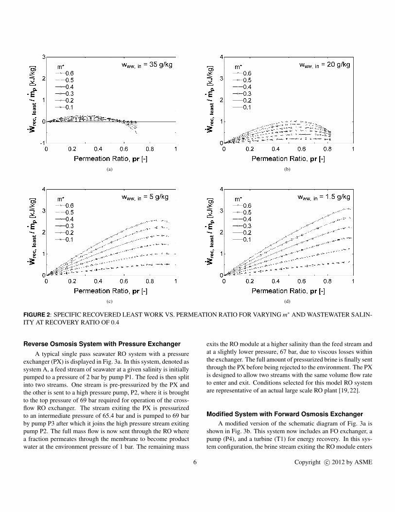
Reversible Model Results and DiscussionWe now plot the equation presented in Eqn. (16) with the
inputs listed in Table 1. Each plot in Figs. 2a–2d shows the re-covered least work per kilogram of product water as a function ofpr and several values of m∗. Four plots are given for wastewatersalinities ranging from 1.5 to 35 g/kg. For a recovery ratio of 0.4,the specific least work of system A alone is 3.63 kJ/kg of productwater.
The recovered least work plots show that in the reversiblecase, considerable reductions in the work required can beachieved for the range of m∗ plotted. Each successive figure al-lows for higher permeation ratios to be used because for lowersalinities of inlet wastewater, pr can approach one. The maxi-mum pr displayed corresponds to a waste water outlet salinityof nearly 120 g/kg which is the salinity limit for a stream in theseawater property package used.
By comparing the figures, several conclusions can be drawn.As expected, a lower inlet wastewater salinity will allow forlarger reductions in least work. We can also note that recov-ered least work increases for increasing m∗. As pr decreases tozero, the recovered least work approaches zero; meaning that thesystem B work is equal to the system A work as less water isextracted from the wastewater stream. An optimum permeationratio exists for each m∗. This is because a trade-off exists be-tween diluting the brine stream coming into the reversible ERDat the expense of rejecting a more highly concentrated wastewa-ter stream. The optimum permeation ratio appears to increase fordecreasing inlet wastewater salinities. This is because at higherinlet wastewater salinities, a high pr will reject a highly concen-trated wastewater stream, penalizing the attainable work reduc-tion. The largest work recovery of 3.1 kJ/kg of product water canbe found for a wastewater salinity of 1.5 g/kg at the local opti-mum permeation ratio of 0.965. This corresponds to a least workof 0.53 kJ/kg of product water for system B.
THERMODYNAMIC ANALYSIS OF IRREVERSIBLESEPARATION
To determine how much work is recovered through use ofthe ERD integrated with an RO system, we must first find theleast work required for the irreversible RO system without en-ergy recovery. We then integrate the system with an additionalpump, an FO-based mass exchanger for energy recovery, and aturbine to recover a fraction of the wastewater pumping losses.The RO system with an FO mass exchanger and pump comprisea system proposed in literature [21]. A wastewater turbine wasadded to the present model after early analyses pointed to exces-sive, recoverable losses in the wastewater pump.
The governing equations used for analysis of the system per-formance are given after the system descriptions.
5 Copyright c© 2012 by ASME
(a) (b)
(c) (d)
FIGURE 2: SPECIFIC RECOVERED LEAST WORK VS. PERMEATION RATIO FOR VARYING m∗ AND WASTEWATER SALIN-ITY AT RECOVERY RATIO OF 0.4
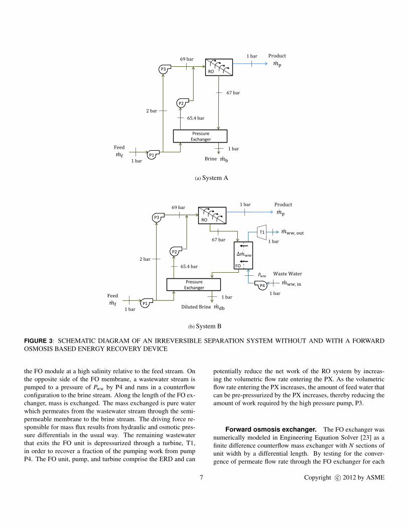
Reverse Osmosis System with Pressure ExchangerA typical single pass seawater RO system with a pressure
exchanger (PX) is displayed in Fig. 3a. In this system, denoted assystem A, a feed stream of seawater at a given salinity is initiallypumped to a pressure of 2 bar by pump P1. The feed is then splitinto two streams. One stream is pre-pressurized by the PX andthe other is sent to a high pressure pump, P2, where it is broughtto the top pressure of 69 bar required for operation of the cross-flow RO exchanger. The stream exiting the PX is pressurizedto an intermediate pressure of 65.4 bar and is pumped to 69 barby pump P3 after which it joins the high pressure stream exitingpump P2. The full mass flow is now sent through the RO wherea fraction permeates through the membrane to become productwater at the environment pressure of 1 bar. The remaining mass
exits the RO module at a higher salinity than the feed stream andat a slightly lower pressure, 67 bar, due to viscous losses withinthe exchanger. The full amount of pressurized brine is finally sentthrough the PX before being rejected to the environment. The PXis designed to allow two streams with the same volume flow rateto enter and exit. Conditions selected for this model RO systemare representative of an actual large scale RO plant [19, 22].
Modified System with Forward Osmosis ExchangerA modified version of the schematic diagram of Fig. 3a is
shown in Fig. 3b. This system now includes an FO exchanger, apump (P4), and a turbine (T1) for energy recovery. In this sys-tem configuration, the brine stream exiting the RO module enters
6 Copyright c© 2012 by ASME
21
𝑚 p
Pressure Exchanger
RO
P1
P2
P3
2 bar
67 bar
1 bar
1 bar 𝑚 f
𝑚 b
69 bar 1 bar
65.4 bar
Feed
Brine
Product
(a) System A
25
𝑚 ww, in
𝑚 ww, out
Pressure Exchanger
RO
P1
P3
P4
2 bar
67 bar
69 bar
𝑃ww
1 bar
1 bar 1 bar
1 bar
1 bar
65.4 bar
𝑚 f 𝑚 db Diluted Brine
Product
Waste Water
P2
Feed
𝑚 p
∆𝑚 ww
FO
T1
(b) System B
FIGURE 3: SCHEMATIC DIAGRAM OF AN IRREVERSIBLE SEPARATION SYSTEM WITHOUT AND WITH A FORWARDOSMOSIS BASED ENERGY RECOVERY DEVICE
the FO module at a high salinity relative to the feed stream. Onthe opposite side of the FO membrane, a wastewater stream ispumped to a pressure of Pww by P4 and runs in a counterflowconfiguration to the brine stream. Along the length of the FO ex-changer, mass is exchanged. The mass exchanged is pure waterwhich permeates from the wastewater stream through the semi-permeable membrane to the brine stream. The driving force re-sponsible for mass flux results from hydraulic and osmotic pres-sure differentials in the usual way. The remaining wastewaterthat exits the FO unit is depressurized through a turbine, T1,in order to recover a fraction of the pumping work from pumpP4. The FO unit, pump, and turbine comprise the ERD and can
potentially reduce the net work of the RO system by increas-ing the volumetric flow rate entering the PX. As the volumetricflow rate entering the PX increases, the amount of feed water thatcan be pre-pressurized by the PX increases, thereby reducing theamount of work required by the high pressure pump, P3.
Forward osmosis exchanger. The FO exchanger wasnumerically modeled in Engineering Equation Solver [23] as afinite difference counterflow mass exchanger with N sections ofunit width by a differential length. By testing for the conver-gence of permeate flow rate through the FO exchanger for each
7 Copyright c© 2012 by ASME
additional section added, N was determined to be fifty sections.
Governing EquationsTo evaluate the pump work associated with pressurizing an
incompressible fluid, Eqn. (17) is used.
Wpump =m(Pout−Pin)
ρηpump(17)
The turbine work associated with depressurizing an incompress-ible fluid is given by Eqn. (18).
Wturb =m(Pin−Pout)ηturb
ρ(18)
The pressure of the feed stream exiting the pressure exchangeris given by Eqn. (19), which is derived by equating the work ofpressurization of the feed stream to the depressurization of thediluted brine stream [19].
Pf,out = Pf, in +ηcompηexp
(mdbρf
ρdbmf
)(Pdb, in−P0) (19)
The differential mass flow rate through each section of theexchanger is a function of four parameters: the water permeabil-ity constant, the differential area of each section, the local dif-ference in osmotic pressure across the membrane, and the localdifference in hydraulic pressure across the membrane:
dmi = ρpureA×Am, i (∆πi−∆Pi) (20)
Here Am, i, in units of square meters, is the differential areaof each membrane section and is given by the total membranearea of the exchanger, Am, divided by N number of sections,Am, i = Am/N. A is defined as the water permeability constant,is a property of the membrane characteristics, and has units ofmeters cubed per second of permeate per square meter per bar[13–15]. The local hydraulic and osmotic pressure differencesare given by Eqns. (21a and 21b):
∆πi = πb, i−πww, i (21a)∆Pi = Pb, i−Pww, i (21b)
The differences in osmotic and hydraulic pressures are equal tothe brine value of the ith section minus the wastewater value ofthe ith section. Both gradients have units of pressure in bar. Equa-tion (20) denotes forward osmosis operation and requires that
∆πi > ∆Pi. For a purely FO unit, the hydraulic pressure differ-ence ∆Pi is zero. For RO operation, ∆Pi > ∆πi. The ERD isFO-based because this system will operate at a hydraulic pres-sure gradient between FO and RO operation. This operation isreferred to in the literature as PRO [2, 8, 10–18].
The mass of the permeate for each section is calculated,added to the brine stream, and subtracted from the wastewa-ter stream. The salinities for subsequent sections are calculatedbased on the new water flow rates which will alter the osmoticpressures in each stream. For simplicity, this model does notconsider changes in hydraulic pressure along the FO module.
The total permeate mass in the forward osmosis exchangeris equal to the sum of the differential mass flow rates througheach section, Eqn. (22).
∆mww =N
∑i=1
dmi (22)
Equations (23a and 23b) define the net work of the compo-nents shown in Fig. (3a and 3b). Equation (23c) presents thedifference of the two net works per kilogram of product water,or the specific recovered work, for assessment of plant perfor-mance.
Wnet,A = WP 1 +WP 2 +WP 3 (23a)
Wnet,B = WP 1 +WP 2 +WP 3 +WP 4−WT 1 (23b)
Wrec
mp=
Wnet,A
mp−
Wnet,B
mp(23c)
A specific recovered work, Eqn. (23c), of greater than zero re-sults in an advantageous use of the ERD.
Dimensionless parameters for irreversible case.In this section we describe dimensionless parameters that areuseful for the irreversible system analysis. From the reversiblecase, we again use recovery ratio, Eqn. (11), to govern thestreams in the RO module. We also use the dimensionless flowrate of wastewater to brine stream, m∗ from Eqn. (13), to definethe flow rate of incoming wastewater in the irreversible case sim-ulations.
8 Copyright c© 2012 by ASME
A new parameter P∗, Eqn. (24), is a pressure ratio definedto set the limits of operation for pump 4 in system B as a valuebetween zero and one.
P∗ ≡ ∆P∆πmax
=Pb, in−Pww, in
πb, in−πww, in(24)
By Eqn. (24), ∆P = 0 when P∗ = 0 which means that pump4 pressurizes the wastewater to match the brine stream pressureat 67 bar (assuming no hydraulic pressure drop in the FO mod-ule). According to Eqn. (20) this will maximize the mass flowrate through the FO exchanger. When P∗ = 1, pump 4 pressur-izes the wastewater stream to the lowest pressure allowable formaintaining forward osmosis operation. A balance between P∗
and m∗ will be required for optimum system performance.
Irreversible model assumptions. In these model sim-ulations we made several assumptions to reduce the problemspace. We neglected hydraulic pressure drop in the FO exchangerand also the presence of internal or external concentration polar-ization. According to Wilf [24], for typical spiral wound sea-water RO membranes, salt rejection rates are about 99.8% witha water permeability of 1.0 L/m2-hr-bar. We neglected salt per-meation through the FO membrane because of the high rejectionrate. The total membrane area for the FO exchanger is equivalentto the total RO membrane area required for a single pass seawaterRO desalination plant with the same amount of product water, asgiven by Wilf [24]. Parameter values used for the simulation arelisted in Table 2. It is also unclear whether current forward os-mosis membranes can withstand the applied hydraulic pressurespresent in the current model [18]. For the recovery ratio chosen,the mass flow rate of the brine and product streams will be 0.6and 0.4 kg/s. The density and osmotic pressure of each streamare evaluated as functions of temperature and salinity using sea-water properties developed by Sharqawy et al. [20].
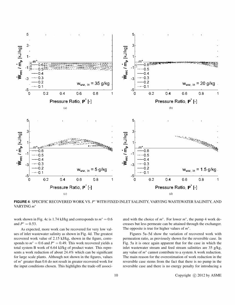
Irreversible Model Results and DiscussionFor the inputs shown in Table 2, the net work required for
system A is a constant 8.798 kJ/kg of product water. The workrecovered by the system with recovery, Eqn. (23c), is plottedagainst P∗ varying between zero and one for a range of m∗ val-ues in Figs. 4a–4d. Each figure corresponds to a value of thewastewater inlet salinity which varies between 35 and 1.5 g/kg.
Figure 4a shows that for a wastewater inlet salinity equal tothat of the feed stream salinity, at any m∗, the addition of the ERDto the RO system is not advantageous. This is because the workrequired by pump 4 is greater than the work saved by pumpingless feed in pump 2. The conclusion is all the more convincinggiven that concentration polarization and pressure drop in the for-ward osmosis exchanger were not considered in this analysis.
TABLE 2: IRREVERSIBLE MODEL INPUTS
Input Value / Range
Ambient temperature T0 25 oC
Ambient pressure P0 1 bar
Feed mass flow rate mf 1 kg/s
Feed salinity wf 35 g/kg
Product salinity wp 0 g/kg
Recovery ratio r 0.4
Pump efficiency ηpump 85%
Turbine efficiency ηturb 80%
PX compression efficiency ηcomp 98%
PX expansion efficiency ηexp 98%
Total FO membrane area Am 100 m2
Permeability coefficient A 2.77×10⁻⁷ m3/m2-s-bar
Mass flow rate ratio m∗ 0.1→ 0.6
Applied pressure ratio P∗ 0→ 1
Inlet wastewater salinity www, in 35→ 1.5 g/kg
For certain values of m∗, the recovered work curves stop forlow values of P∗. This end point is termed ‘end of operation’ andis due to an unacceptably high net driving force across the mem-brane which would result in more permeate flow than providedby the wastewater stream.
For a wastewater inlet salinity of 20 g/kg, in Fig. 4b, we be-gin to see a point at which the ERD is advantageous for P∗ valuesof between 0.4 to 0.8. The concave shape of each recovered workcurve is due to the trade-off associated with a high or low valueof P∗. For low P∗, the pump 4 work increases, but more perme-ate is allowed through the FO exchanger. For high values of P∗
the opposite is true.Figure 4c clearly shows that for a wastewater salinity of 5
g/kg an optimal value of P∗ exists for each m∗ curve. This op-timum point shifts to higher values of P∗ for smaller values ofm∗. Theoretically, as published in literature, the maximum workobtainable by a zero-dimension (1 section) PRO exchanger usedfor power production is where ∆P=∆π/2 [11,13–15]. Althoughit is not entirely analogous (because the system considered inthis paper does not produce work), Fig. 4c shows that for a one-dimension exchanger the optimal pressure is not at half of themaximum osmotic pressure gradient and that it also varies withm∗ for a fixed inlet wastewater salinity. The greatest recovered
9 Copyright c© 2012 by ASME
(a) (b)
(c) (d)
FIGURE 4: SPECIFIC RECOVERED WORK VS. P∗ WITH FIXED INLET SALINITY, VARYING WASTEWATER SALINITY, ANDVARYING m∗
work shown in Fig. 4c is 1.74 kJ/kg and corresponds to m∗ = 0.6and P∗ = 0.53.
As expected, more work can be recovered for very low val-ues of inlet wastewater salinity as shown in Fig. 4d. The greatestrecovered work value of 2.15 kJ/kg, shown in the figure, corre-sponds to m∗ = 0.6 and P∗ = 0.49. This work recovered yields atotal system B work of 6.64 kJ/kg of product water. This repre-sents a work reduction of about 24.4% which can be significantfor large scale plants. Although not shown in the figures, valuesof m∗ greater than 0.6 do not result in greater recovered work forthe input conditions chosen. This highlights the trade-off associ-
ated with the choice of m∗. For lower m∗, the pump 4 work de-creases but less permeate can be attained through the exchanger.The opposite is true for higher values of m∗.
Figures 5a–5d show the variation of recovered work withpermeation ratio, as previously shown for the reversible case. InFig. 5a it is once again apparent that for the case in which theinlet wastewater stream and feed stream salinities are 35 g/kg,any value of m∗ cannot contribute to a system A work reduction.The main reason for the overestimation of work reduction in thereversible case stems from the fact that there is no pump in thereversible case and there is no energy penalty for introducing a
10 Copyright c© 2012 by ASME

(a) (b)
(c) (d)
FIGURE 5: SPECIFIC RECOVERED WORK VS. PERMEATION RATIO WITH FIXED INLET SALINITY, VARYING WASTEWA-TER SALINITY, AND VARYING m∗
large mass flow rate of wastewater stream into the system. Thispump work penalty can also been seen by the fact that when pr isequal to zero, i.e., when zero wastewater permeates through theforward osmosis membrane, the recovered work does not equalzero as it did in the reversible case. This is because of the en-ergy penalty associated with pumping the wastewater through theERD system regardless of whether permeate was forced throughthe membrane. Similar to the reversible case, the other figuresalso exhibit the existence of an optimum pr which increases withdecreasing wastewater inlet salinity.
CONCLUSIONSDesalination systems reject a highly concentrated discharge
brine which has a higher Gibbs free energy than the feed stream.With a forward osmosis mass exchanger, a portion of this energycan be recovered to reduce the system’s net work of separation. Aforward osmosis based energy recovery device can also be usedto recover work from an available wastewater stream of a salinityless than that of the rejected brine stream.
Expressions were derived to describe the least work of sepa-ration for a system without and with a reversible energy recoverydevice. Along with the recovery ratio, two new dimensionlessparameters relating the mass flow rates in the reversible energyrecovery device, m∗, and permeation ratio, pr, were defined to as-sess the performance of a system with energy recovery. In addi-
11 Copyright c© 2012 by ASME
tion to investigating the thermodynamic limits of separation for areversible system, a simple model of an irreversible component-based system with and without energy recovery was numericallysimulated.
The major conclusions of this paper are as follows:
1. Reversible results suggest that significant work reductionscan be made with an energy recovery device. Results showthat only small reductions in net least work can be madewhen an inlet wastewater stream salinity equal to that of thefeed is used.
2. For maximum work recovery, a wastewater turbine is recom-mended to recover a fraction of the energy penalty incurredin pumping the wastewater into the FO mass exchanger.
3. With reasonable assumptions made with respect to the FOmembrane area and characteristics, the irreversible caseshows that for an inlet wastewater stream and feed streamof 35 g/kg salinity, an energy recovery device is not advan-tageous under any circumstances. This conclusion is mademore convincing by recognizing that concentration polariza-tion and pressure drop in the forward osmosis membranewill further contribute to losses in the system.
4. An optimal hydraulic pressure difference between streams inthe FO exchanger exists for maximum work reduction. Thispressure, contrary to expressions found in the literature, wasnot found to equal half of the maximum osmotic pressuredifference between the streams.
ACKNOWLEDGMENTThe authors would like to thank the King Fahd University of
Petroleum and Minerals in Dhahran, Saudi Arabia, for fundingthe research reported in this paper through the Center for CleanWater and Clean Energy at MIT and KFUPM under PROJECTNUMBER R4-CW-08.
REFERENCES[1] IDA, 2011 - 2012. Desalination Yearbook, Section 1. Mar-
ket Profile. International Desalination Association.[2] Cath, T. Y., Childress, A. E., and Elimelech, M., 2006.
“Forward osmosis: Principles, applications, and recent de-velopments”. Journal of Membrane Science, 287, pp. 70–87.
[3] McCutcheon, J. R., McGinnis, R. L., and Elimelech, M.,2006. “Desalination by ammonia-carbon dioxide forwardosmosis: Influence of draw and feed solution concentra-tions on process performance”. Journal of Membrane Sci-ence, 278, pp. 114–123.
[4] McGinnis, R. L., and Elimelech, M., 2007. “Energy re-quirements of ammonia-carbon dioxide forward osmosisdesalination”. Desalination, 207, pp. 370–382.
[5] Bamaga, O., Yokochi, A., Zabara, B., and Babaqi, A., 2011.“Hybrid fo/ro desalination system: Preliminary assessmentof osmotic energy recovery and designs of new fo mem-brane module configurations”. Desalination, 268, pp. 163–169.
[6] Liberman, B., and Greenberg, G., 2011. “Recovery of os-motic power in swro plants”. In IDA World Congress/PerthConvention and Exhibition Centre (PCEC).
[7] Loeb, S., 1975. “Osmotic power plants”. Science, 189,pp. 654–655.
[8] Loeb, S., 2002. “Large-scale power production by pressure-retarded osmosis, using river water and sea water passingthrough spiral modules”. Desalination, 143, pp. 115–122.
[9] McGinnis, R. L., McCutcheon, J. R., and Elimelech, M.,2007. “A novel ammonia-carbon dioxide osmotic heat en-gine for power generation”. Journal of Membrane Science,305, pp. 13–19.
[10] Skilhagen, S. E., Dugstad, J. E., and Aaberg, R. J., 2007.“Osmotic power - power production based on the osmoticpressure difference between waters with varying salt gradi-ents”. Desalination, 220, pp. 476–482.
[11] Sharqawy, M. H., Zubair, S. M., and Lienhard V, J. H.,2011. “Second law analysis of reverse osmosis desalina-tion plants: An alternative design using pressure retardedosmosis”. Energy, 36, pp. 6617–6626.
[12] Enomoto, H., Fujitsuka, M., Hasegawa, T., Kuwada, M.,Tanioka, A., and Minagawa, M., 2010. “A feasibilitystudy of pressure-retarded osmosis power generation sys-tem based on measuring permeation volume using reverseosmosis membrane”. Electrical Engineering in Japan,173, pp. 1129–1138.
[13] Lee, K., Baker, R., and Lonsdale, H., 1981. “Membranesfor power generation by pressure-retarded osmosis”. Jour-nal of Membrane Science, 8, pp. 141–171.
[14] Achilli, A., Cath, T. Y., and Childress, A. E., 2009. “Powergeneration with pressure retarded osmosis: An experimen-tal and theoretical investigation”. Journal of Membrane Sci-ence, 343, pp. 42–52.
[15] Achilli, A., and Childress, A. E., 2010. “Pressure retardedosmosis: From the vision of sidney loeb to the first proto-type installation – review”. Desalination, 261, pp. 205–211.
[16] Post, J. W., Veerman, J., Hamelers, H. V., Euverink, G. J.,Metz, S. J., Nymeijer, K., and Buisman, C. J., 2007.“Salinity-gradient power: Evaluation of pressure-retardedosmosis and reverse electrodialysis”. Journal of MembraneScience, 288, pp. 218–230.
[17] van der Zwan, S., Pothof, I. W., Blankert, B., and Bara, J. I.,2012. “Feasibility of osmotic power from a hydrodynamicanalysis at module and plant scale‘”. Journal of MembraneScience, 389, pp. 324–333.
[18] Ramon, G. Z., Feinberg, B. J., and Hoek, E. M. V., 2011.
12 Copyright c© 2012 by ASME
“Membrane-based production of salinity-gradient power”.Energy & Environmental Science, 4, pp. 4423–4434.
[19] Mistry, K. H., McGovern, R. K., Thiel, G. P., Summers,E. K., Zubair, S. M., and Lienhard V, J. H., 2011. “Entropygeneration analysis of desalination technologies”. Entropy,13(10), pp. 1829–1864.
[20] Sharqawy, M. H., Lienhard V, J. H., and Zubair, S. M.,2010. “Thermophysical properties of seawater: A reviewof existing correlations and data”. Desalination and WaterTreatment, 16, pp. 354–380.
[21] Liberman, B., 2010. “Present and future: Energy efficientseawater desalination”. In Desalination: an energy solution,International Desalination Association.
[22] ERI, 2012. “Energy recovery inc. power model”.http://www.energyrecovery.com/index.cfm/0/0/56-Power-Model.html, April.
[23] Klein, S., 2011. Engineering equation solver v8.881-3d.F-Chart Software, February.
[24] Wilf, M., 2007. The Guidebook to Membrane DesalinationTechnology. Balaban Desalination Publications.
13 Copyright c© 2012 by ASME


![Entropy generation minimization in desalinationweb.mit.edu/lienhard/www/papers/conf/LIENHARD_IMECE18... · 2019-03-10 · sep Workofseparation[W] wk Massfractionofspeciesk[gkg1] Xi](https://img.pdfslide.us/doc/110x75/5ed041e02f7c6c10f86c6e77/entropy-generation-minimization-in-2019-03-10-sep-workofseparationw-wk-massfractionofspecieskgkg1.jpg)