Embed Size (px)
Citation preview

Draft: September 2006 Presentation to State Board of Education: October 2006
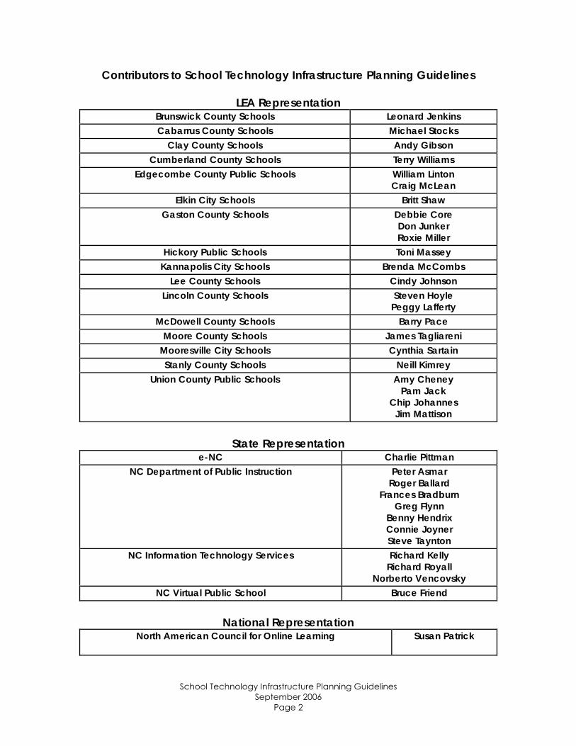
Contributors to School Technology Infrastructure Planning Guidelines
LEA Representation Brunswick County Schools Leonard Jenkins Cabarrus County Schools Michael Stocks
Clay County Schools Andy Gibson Cumberland County Schools Terry Williams
Edgecombe County Public Schools William Linton Craig McLean
Elkin City Schools Britt Shaw Gaston County Schools Debbie Core
Don Junker Roxie Miller
Hickory Public Schools Toni Massey Kannapolis City Schools Brenda McCombs
Lee County Schools Cindy Johnson Lincoln County Schools Steven Hoyle
Peggy Lafferty McDowell County Schools Barry Pace
Moore County Schools James Tagliareni Mooresville City Schools Cynthia Sartain Stanly County Schools Neill Kimrey
Union County Public Schools Amy Cheney Pam Jack
Chip Johannes Jim Mattison
State Representation
e-NC Charlie Pittman NC Department of Public Instruction Peter Asmar
Roger Ballard Frances Bradburn
Greg Flynn Benny Hendrix Connie Joyner Steve Taynton
NC Information Technology Services Richard Kelly Richard Royall
Norberto Vencovsky NC Virtual Public School Bruce Friend
National Representation
North American Council for Online Learning Susan Patrick
School Technology Infrastructure Planning Guidelines
September 2006 Page 2
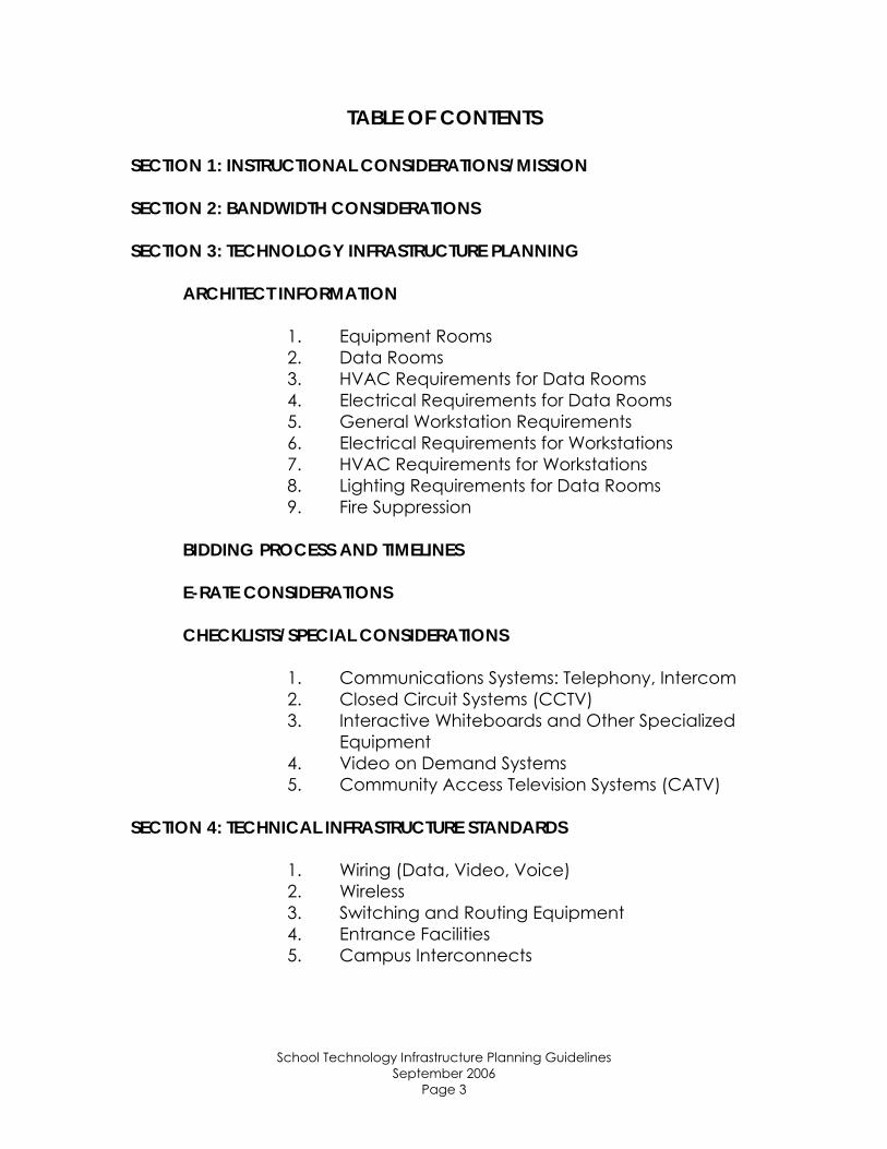
TABLE OF CONTENTS
SECTION 1: INSTRUCTIONAL CONSIDERATIONS/MISSION SECTION 2: BANDWIDTH CONSIDERATIONS SECTION 3: TECHNOLOGY INFRASTRUCTURE PLANNING
ARCHITECT INFORMATION
1. Equipment Rooms 2. Data Rooms 3. HVAC Requirements for Data Rooms 4. Electrical Requirements for Data Rooms 5. General Workstation Requirements 6. Electrical Requirements for Workstations 7. HVAC Requirements for Workstations 8. Lighting Requirements for Data Rooms 9. Fire Suppression
BIDDING PROCESS AND TIMELINES E-RATE CONSIDERATIONS CHECKLISTS/SPECIAL CONSIDERATIONS
1. Communications Systems: Telephony, Intercom 2. Closed Circuit Systems (CCTV) 3. Interactive Whiteboards and Other Specialized
Equipment 4. Video on Demand Systems 5. Community Access Television Systems (CATV)
SECTION 4: TECHNICAL INFRASTRUCTURE STANDARDS
1. Wiring (Data, Video, Voice) 2. Wireless 3. Switching and Routing Equipment 4. Entrance Facilities 5. Campus Interconnects
School Technology Infrastructure Planning Guidelines September 2006
Page 3
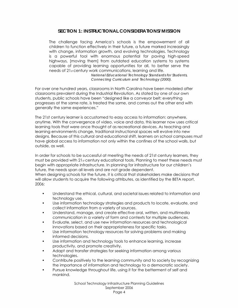
SECTION 1: INSTRUCTIONAL CONSIDERATIONS/MISSION
The challenge facing America’s schools is the empowerment of all children to function effectively in their future, a future marked increasingly with change, information growth, and evolving technologies. Technology is a powerful tool with enormous potential for paving high-speed highways, [moving them] from outdated education systems to systems capable of providing learning opportunities for all, to better serve the needs of 21st century work communications, learning and life.
National Educational Technology Standards for Students, Connecting Curriculum and Technology (2000).
For over one hundred years, classrooms in North Carolina have been modeled after classrooms prevalent during the Industrial Revolution. As stated by one of our own students, public schools have been “designed like a conveyor belt; everything progresses at the same rate, is treated the same, and comes out the other end with generally the same experiences.” The 21st century learner is accustomed to easy access to information: anywhere, anytime. With the convergence of video, voice and data, this learner now uses critical learning tools that were once thought of as recreational devices. As teaching and learning environments change, traditional instructional spaces will evolve into new designs. Because of this cultural and educational shift, learners on school campuses must have global access to information not only within the confines of the school walls, but outside, as well. In order for schools to be successful at meeting the needs of 21st century learners, they must be provided with 21st century educational tools. Planning to meet these needs must begin with appropriate infrastructure. In planning for infrastructure for our children’s future, the needs span all levels and are not grade dependent. When designing schools for the future, it is critical that stakeholders make decisions that will allow students to acquire the following attributes, as identified by the BETA report, 2006:
• Understand the ethical, cultural, and societal issues related to information and technology use.
• Use information technology strategies and products to locate, evaluate, and collect information from a variety of sources.
• Understand, manage, and create effective oral, written, and multimedia communication in a variety of form and contexts for multiple audiences.
• Evaluate, select, and use new information resources and technological innovations based on their appropriateness for specific tasks.
• Use information technology resources for solving problems and making informed decisions.
• Use information and technology tools to enhance learning, increase productivity, and promote creativity.
• Adapt and transfer strategies for seeking information among various technologies.
• Contribute positively to the learning community and to society by recognizing the importance of information and technology to a democratic society.
• Pursue knowledge throughout life, using it for the betterment of self and mankind.
School Technology Infrastructure Planning Guidelines September 2006
Page 4
The following checklist should be used to ensure school design adheres to current minimum standards:
WAN and LAN bandwidth to support administrative applications (i.e. NC WISE, HRMS, AS400, Voice over IP), and instructional needs (i.e. distance learning, virtual schools, streaming media, NC WISE OWL)
Infrastructure designed to support convergent applications (voice, video, data) and allow for future expansion and new technologies
Infrastructure which reflects flexible use of space, and supports connections within the school as well as outside to community and home
Infrastructure designed for access equivalent to or exceeding that specified in the Information Access and Delivery chapter of IMPACT: Guidelines for North Carolina Media and Technology Programs, including:
• A minimum of eight data ports per classroom, located per direction of district instructional staff. (Note: Functional wireless overlay at time of construction may affect this number.)
• A minimum of two wired data ports of LAN access for administrative spaces, conference rooms, workrooms, auditoriums, cafeterias, and gymnasiums
• A data port for each workstation and printer in computer labs (number based on school population and/or local standards)
• A data port for each workstation and printer in media centers (number based on school population and/or local standards)
• Provision for telephones in each classroom, media center, and technology lab
• School-wide intercom system • Provision for digital interactive whiteboard and ceiling-mounted data,
including electrical and data provisions for projection in each classroom, media center, and technology lab
• Provision for wireless local area network (WLAN) implementation, including public areas of school, including any necessary pathways and electrical needs.
References for 21st Century Learning and Design:
International Society for Technology in Education. (2000). National educational standards for students: Connecting curriculum and technology.
North Central Regional Education Laboratory and the Metiri Group. (2003). enGauge 21st century skills: Literary in the digital age. Retrieved June 20, 2006, from http://www.ncrel.org/engauge/skills/engauge21st.pdf.
Partnership for 21st Century Skills. (n.d.). Learning for the 21st century: A report and mile guide for 21st century skills. Retrieved June 20, 2006, from http://www.21stcenturyskills.org/images/stories/otherdocs/P21_Report.pdf.
Public Schools of North Carolina, Information Technology Division. (2005). IMPACT: Guidelines for North Carolina media and technology programs. Retrieved June 20, 2006, from http://www.ncwiseowl.org/zones/mediatech/impact/IMPACT.pdf.
School Technology Infrastructure Planning Guidelines September 2006
Page 5
SECTION 2: BANDWIDTH CONSIDERATIONS
1.0 INTRODUCTION
A. This section address issues associated with bandwidth and Internet access requirements for new and existing schools.
B. Consideration is given for both the Local Education Authority (LEA) to the Internet connection and the LEA to schools connection.
2.0 REFERENCES
A. This is the combined recommendations from personnel at DPI, e-NC
Authority, ITS, NCREN and LEA technology directors. B. The e-NC Authority. (2006). Developing Regional Education Networks.
3.0 BETA RECOMMENDATIONS
A. K-12 instructional and business needs will drive the ever-increasing need for connectivity and bandwidth. As states and their school systems have risen to the connectivity challenge, a greater sophistication of analysis has transpired. Initially it was commonly held that every school should have T1 (1.5 Mbps) access as a minimum. This standard is no longer sufficient for optimal access to use of the various learning and administrative applications of a school. 1. Provide minimum connectivity, enabling specific and appropriate
connectivity levels consistent with needs of individual schools. 2. Ensure a minimum standard of connectivity for all schools and
ensure upgrading as needed. 3. Initial bandwidth available from each school location to the PoP
will be 100 Mbps Ethernet interface (as available) and will be capable of upward adjustment in arbitrary increments up to the max of 1Gbps.
4. Provide high-speed Internet and Internet2 access (where available).
4.0 GENERAL
A. Planning for bandwidth should include requirements for security, video and Voice over IP in addition to other administrative and curriculum requirements.
B. All links should be continuously monitored for bandwidth usage and performance.
C. A 100/1000 Ethernet interface should be used for all transport interfaces. D. Pricing for network access should be based on usage.
5.0 INTERNET – LEA – SCHOOL CONNECTIONS
A. There are many providers that are able to serve LEA and school locations. The provider companies will be different for different areas of the state.
B. It is recommended that any chosen provider PEERs with NCREN or ITS. This keeps state traffic within the state on a secure network, with in-state engineering and control, and keeps in-state traffic off the Internet.
School Technology Infrastructure Planning Guidelines September 2006
Page 6

C. Include in the contract language which states that the provider may neither filter nor log TCP/IP traffic or connections in any way. The only exception should be for network troubleshooting or investigation at the request of the LEA or law enforcement.
D. Provide at least 100 Mbps physical links from the LEA to the schools.
School Technology Infrastructure Planning Guidelines September 2006
Page 7
SECTION 3: TECHNOLOGY INFRASTRUCTURE PLANNING
ARCHITECTURAL INFORMATION
1.0 INTRODUCTION
A. With computer technology has come a new and different set of spatial and environmental constraints that must be recognized and incorporated into our buildings so that equipment may be used effectively. Classrooms need to be larger to accommodate new equipment, additional rooms and closets are required to support the technology, and the new equipment places increased demands upon electrical and air-conditioning systems. This section should be used in conjunction with the STS-1000 Telecommunications Wiring Guidelines and IMPACT: Guidelines for North Carolina Media and Technology Programs.
2.0 REFERENCES
A. BICSI. (2006). Telecommunications distribution methods manual. (11th Ed.) Tampa, FL: BICSI.
3.0 MAIN WIRING CLOSET (MAIN CROSS-CONNECT (MC), HEAD-END OR MDF)
A. Main wiring closets shall be designed according to specifications of the most recent edition of the TDMM. Key considerations are included in this section.
B. The main wiring closet shall be designed to incorporate a variety of systems, including voice, data, CATV, security, and other building systems. This design may vary if there is a separate video production/CATV head-end room. Please verify preference with Owner. Provision for the demarcation point shall also be included in room which houses the MC.
C. This closet should be centrally located whenever possible, and provide adequate space for immediate equipment needs as well as future expansion.
D. Several factors should be considered when locating the main wiring closet: 1. It should be located far enough from sources from EMI to
reduce/eliminate interference. 2. It should be located in places not subject to water or steam
interference, or other sources of humidity. 3. It should be located away from heat sources. 4. Room should be free of electrical and plumbing sources not
directed related to telecommunications function. E. At minimum, a main wiring closet should include square footage of 10’ x
15’. F. A minimum of four 4” sleeves shall be provided. G. Doors shall be a minimum of 3’ wide and 80” tall, and shall open outward.
Double doors are recommended for these spaces. H. A minimum of 3' of clearance from the farthest protruding equipment shall
be provided front and back of racks or cabinets to be compliant with NESC / NEC, adopted as the NCEC.
School Technology Infrastructure Planning Guidelines
September 2006 Page 8
4.0 INTERMEDIATE WIRING CLOSETS (INTERMEDIATE CROSS-CONNECT (IC), OR IDF)
A. Intermediate wiring closets shall be designed according to specifications of the most recent edition of the TDMM. Key considerations are included in this section.
B. Intermediate wiring closets shall be designed to incorporate a variety of systems, including voice, data, CATV, security, and other building systems.
C. There shall be a minimum of one IC per floor. ICs in multiple-floor buildings shall be stacked vertically.
D. The size of an intermediate closet shall be determined by space served. Guidelines are: 1. 5000 square feet or less: 10’ x 8’ 2. >5000 square feet and <8000 square feet: 10’ x 9’ 3. >8000 square feet and <10000 square feet: 10’ x 11’ 4. >10000 square feet: more than one TR is required.
E. ICs shall be located no more than 295’ apart. F. Minimum ceiling height shall be 8’ above finished floor. Consideration shall
be given to a height of 10’ above finished floor. G. A minimum of four 4” sleeves shall be provided. H. Flooring shall be tile/VCT. I. Doors shall be a minimum of 3’ wide and 80” tall, and shall open outward. J. A minimum of 3’ of clearance shall be provided at front and back of
racks or cabinets, as well as one side, to provide necessary clearance.
5.0 HVAC REQUIREMENTS FOR DATA ROOMS
A. Telecommunications equipment is required to function 24 hours a day, 365 days a year. As such, a stand-alone HVAC unit with independent controls is required for the main wiring closet, and strongly recommended for intermediate closets.
B. If an emergency power source is available, the HVAC system for the main wiring closet should be connected to it.
C. It is important to confirm with Owner the requirements of equipment to be housed in data rooms to insure adequate HVAC capacity.
D. Environmental control standards for data rooms: 1. Temperature shall be between 64 and 75 degrees Fahrenheit. 2. Relative humidity shall be between 30% and 55%.
6.0 ELECTRICAL REQUIREMENTS FOR DATA ROOMS
A. Main wiring closets shall include: 1. Adequate power to support planned equipment for space, as well
as room for future expansion. At minimum, a minimum of 1 – 30A or 2 – 20A circuits should be provided.
2. A minimum of two dedicated nonswitched three conductor 120 volt (V) alternating current (ac) duplex electrical outlets for equipment power, each on separate branch circuits.
3. Additional electrical outlets or power strips may be required, depending on the amount and type of equipment planned for the MC. Confirm with Owner early in the design phase.
School Technology Infrastructure Planning Guidelines September 2006
Page 9
B. Intermediate wiring closets shall include: 1. Branch circuits for equipment power that are protected and
cabled for 20 A capacity. 2. A minimum of two dedicated nonswitched three conductor 120
volt (V) alternating current (ac) duplex electrical outlets for equipment power, each on separate branch circuits.
3. Separate duplex 120 Vac convenience electrical outlets (for tools, field test instruments, etc.), which are located at least 6” above finished floor, and placed at 6’ intervals around perimeter walls.
4. Additional electrical outlets or power strips may be required, depending on the amount and type of equipment planned for the IC. Confirm with Owner early in the design phase.
7.0 FIRE SUPPRESSION REQUIREMENTS FOR DATA ROOMS
A. Rooms containing active equipment should be equipped with pre-action dry pipe sprinkler systems. These should be surrounded by wire cages.
B. Rooms not containing active equipment, with no potential of housing active equipment in the future, may be sprinkled with standard wet pipe sprinkler systems.
8.0 GENERAL WORKSTATION REQUIREMENTS
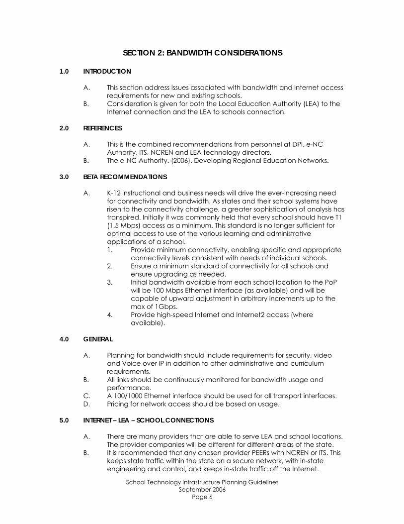
A. More than two or three computers in a classroom can have a significant impact upon spatial needs. Many classrooms are being equipped with five student computers, plus a workstation for the teacher. Even more are often planned for math, science or vocational classrooms. Each of these workstations requires between 15 and 20 square feet. Printers need about the same amount of space. Roughly 100-125 square feet should be allocated for classroom computers.
B. Typical workstation layout: C. Location of workstations and design of labs should be confirmed with
district technology staff. Visibility of monitors by instructional staff should be a primary concern. Workstations should be located away from wet or dusty areas, and located so that glare will not be an issue.
School Technology Infrastructure Planning Guidelines September 2006
Page 10
D. A computer lab should generally be 1,000-1,200 square feet. E. See Impact: Guidelines for North Carolina Media and Technology
Programs for additional information and guidelines.
9.0 ELECTRICAL REQUIREMENTS FOR WORKSTATIONS
A. No more than six computers with monitors should be connected to a single 20 amp circuit.
B. For a typical classroom, one to two circuits with two or more duplex outlets per workstation should be installed.
C. A circuit should also be installed for television and media retrieval/Video on Demand.
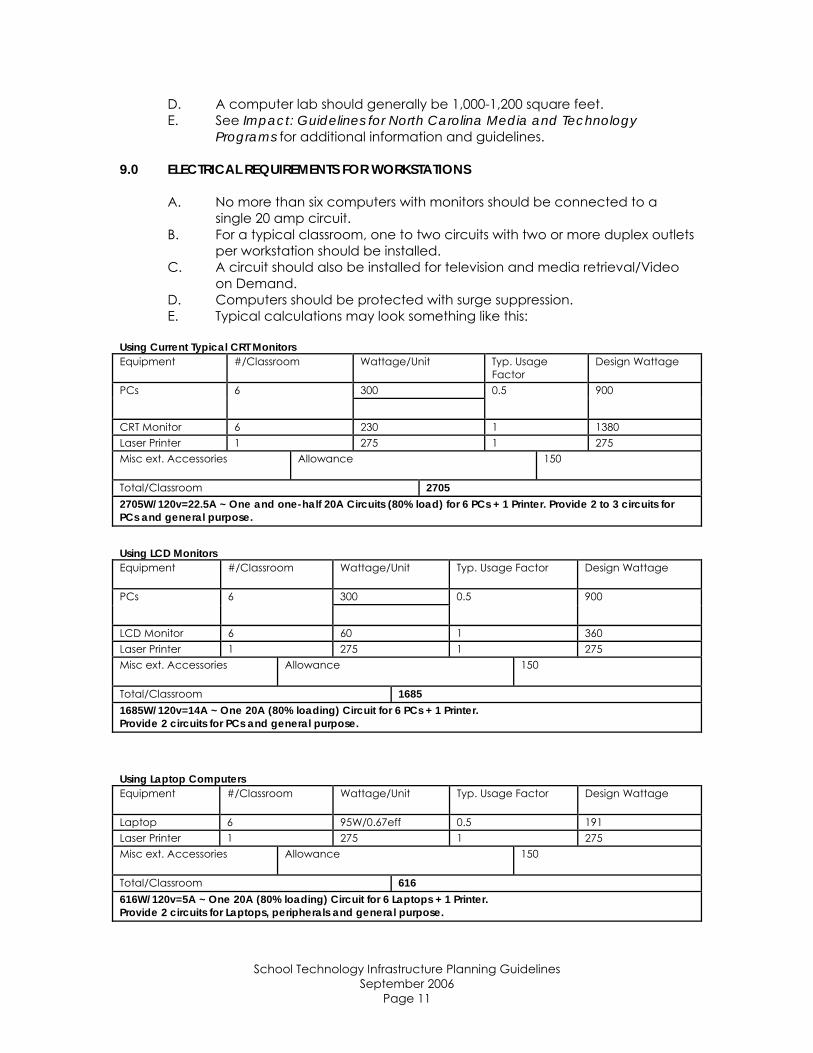
D. Computers should be protected with surge suppression. E. Typical calculations may look something like this:
Using Current Typical CRT Monitors Equipment #/Classroom Wattage/Unit Typ. Usage
Factor Design Wattage
300 PCs 6
0.5 900
CRT Monitor 6 230 1 1380 Laser Printer 1 275 1 275 Misc ext. Accessories Allowance 150
2705 Total/Classroom 2705W/120v=22.5A ~ One and one-half 20A Circuits (80% load) for 6 PCs + 1 Printer. Provide 2 to 3 circuits for PCs and general purpose.
Using LCD Monitors Equipment #/Classroom Wattage/Unit Typ. Usage Factor Design Wattage
300 PCs 6
0.5 900
LCD Monitor 6 60 1 360 Laser Printer 1 275 1 275 Misc ext. Accessories Allowance 150
1685 Total/Classroom 1685W/120v=14A ~ One 20A (80% loading) Circuit for 6 PCs + 1 Printer. Provide 2 circuits for PCs and general purpose.
Using Laptop Computers Equipment #/Classroom Wattage/Unit Typ. Usage Factor Design Wattage
Laptop 6 95W/0.67eff 0.5 191 Laser Printer 1 275 1 275 Misc ext. Accessories Allowance 150
616 Total/Classroom 616W/120v=5A ~ One 20A (80% loading) Circuit for 6 Laptops + 1 Printer. Provide 2 circuits for Laptops, peripherals and general purpose.
School Technology Infrastructure Planning Guidelines September 2006
Page 11
F. Computers can generate high levels of electrical harmonic distortion. This can cause problems when numerous computers are installed. In this case, special considerations such as oversized neutral wires, separate, equally sized neutral for each circuit and specially designed transformers with a higher "K" rating should be specified by an electrical engineer.
G. Ideal placement of power and network outlets is within a solid wall. Workstations located in the center of the room on tables or on casework are much more difficult to supply with power and network cables. Freestanding workstations must be supplied either from overhead by the use of power poles, from floor mounted receptacles, low (table height) knee walls or furniture with built-in wire management capability. Knee walls are preferred, but they limit flexibility in furniture arrangement and the future alteration of space. Power poles and certain types of floor receptacles have significant disadvantages.
H. Often, only limited numbers of computers per classroom are initially wired and installed, with plans to add several more per room in the future. In order to reduce the cost of future installation, limit the amount of exposed future wiring, and reduce the time needed to install future workstations yet retain low initial costs for wiring and cabling, a prudent school system will install empty power and network boxes with conduit during the initial installation. These empty boxes may be wired when needed without breaking into walls, installing unsightly exposed raceways/wires, or performing some other destructive measure. Empty conduits (with a pull cord) should be stubbed above the ceiling for future access, or, for slightly additional cost, stubbed and capped at the entrance to the main cable trays running down the corridors.
10.0 HVAC REQUIREMENTS FOR WORKSTATIONS
A. Computers require a relatively narrow band of temperature and humidity for their operation. If this band is exceeded, they often will stop working unexpectedly, their lifespan may be significantly reduced and/or they may suffer permanent damage. A typical single personal computer may produce over 1,500 BTUH of heat, depending upon the amount of options installed and the type of monitor (including an allowance for a shared laser printer for each six workstations).
B. This computer load translates to ¾ of a ton of air conditioning for six computers with CRT monitors and a printer or ½ ton if using LCD monitors. Small air conditioning equipment is manufactured in logical ½ ton steps (larger equipment, such as for an entire wing, may be in 5- or 10-ton steps). For a typical classroom with a two- to three-ton air-conditioning load without computers, this can mean an additional ton of air conditioning equipment for six computers.
C. Computer labs where twenty to thirty desktops are installed will have a cooling load of four to five times that of a typical classroom with only six computers. Because of this high simultaneous load, it is prudent to provide cooling for this lab on a separate zone or a standalone HVAC system (such as a heat pump) for this space.
School Technology Infrastructure Planning Guidelines September 2006
Page 12
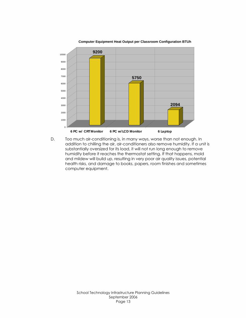
9200
5750
2094
0
1000
2000
3000
4000
5000
6000
7000
8000
9000
10000
6 PC w/ CRT Monitor 6 PC w/LCD Monitor 6 Laptop
Computer Equipment Heat Output per Classroom Configuration BTUh
D. Too much air-conditioning is, in many ways, worse than not enough. In addition to chilling the air, air-conditioners also remove humidity. If a unit is substantially oversized for its load, it will not run long enough to remove humidity before it reaches the thermostat setting. If that happens, mold and mildew will build up, resulting in very poor air quality issues, potential health risks, and damage to books, papers, room finishes and sometimes computer equipment.
School Technology Infrastructure Planning Guidelines September 2006
Page 13
BIDDING PROCESS AND TIMELINES
1.0 INTRODUCTION
A. It is the purpose of this document to identify a recommended process for bids relating to network infrastructure.
B. These guidelines are intended for all new K-12 buildings, additions and renovations.
2.0 REFERENCES
A. All bids must follow current guidelines and statutory authority of the State of North Carolina, as well as applicable federal statutes and policies of State and Local Boards of Education. Guidance may be found in the following references: 1. North Carolina General Statute 143, Article 8. Retrieved June 20,
2006, from http://www.ncga.state.nc.us/EnactedLegislation/ Statutes/HTML/ByChapter/Chapter_143.html.
2. North Carolina Administrative Code, Subchapter 06.A. 3. North Carolina Information Technology Services. (2000). North
Carolina information technology procurement: Policies and procedures. Retrieved June 20, 2006, from http://www.its.state.nc.us/ITProcurement/Documents/itpp.pdf.
3. Bluestein, F. S. (2004). A legal guide to purchasing and contracting for North Carolina local governments (2nd ed.). Chapel Hill: Institute of Government.
4. Bluestein, F. S. (2005). An overview of contract bidding requirements for North Carolina local governments (2nd ed.). Retrieved June 20, 2006, from http://ncinfo.iog.unc.edu/pubs/electronicversions/pdfs/purch.pdf.
5. Fleming, A., F., II. (1996). Construction contracts with North Carolina local governments. Chapel Hill: Institute of Government.
B. This document shall not restate requirements referenced in documents above. Any individual or group involved in competitive bidding should become familiar with these requirements prior to beginning the process.
3.0 BIDS FOR TECHOLOGY IN NEW CONSTRUCTION
A. Bids for technology elements of new construction typically fall into two categories: 1. Formal bids:
a. Construction or repair contracts of $300,000 or above (G.S. 143-129)
b. Purchase of apparatus, supplies, materials and equipment: $90,000 and above (G.S. 143-129).
2. Informal bids: a. Construction or repair contracts of $5,000 to formal limit
(G.S. 143-131) b. Purchase of apparatus, supplies, materials and equipment
of $5,000 to formal limit (G.S. 143-131).
School Technology Infrastructure Planning Guidelines September 2006
Page 14

3. This document will deal primarily with requirements and recommendations for formal bids for technology infrastructure in construction or renovation.
4.0 RECOMMENDED BID STRUCTURE
A. Because of the rapidly changing nature of materials needed to provide technology infrastructure, it is strongly recommended that data and voice cabling in construction projects be bid separately from a general contract, typically at a later time.
B. Other systems which rely on network connectivity should be considered for inclusion in the separate Network/Special Systems bid package. These include, but are not limited to: 1. Intercom and Phone Systems (Traditional or Voice over IP) 2. CATV Systems 3. Media Retrieval/Video on Demand systems 4. Closed Circuit Surveillance Systems 5. Energy Management Systems.
C. Not only does a separate Network/Special Systems contract provide for the most current technology, but it also allows protection of Best Value Procurement codes, as described below.
5.0 BEST VALUE PROCUREMENT
A. As provided in 09 NCAC 06A .0101, Information Technology Procurement: 1. “Best value procurement is defined as a procurement process that
has as a fundamental objective the reduction of total cost of ownership. The particular procurement methods used are selected so as to result in the best buy for the state in terms of the function to be performed. Competitive best value procurement allows for the use of alternate competitive purchasing techniques in addition to low price analysis in the selection of supply sources determined to represent best value.”
2. Evaluation factors for Best Value Procurement must be set forward in the solicitation for bids. This may readily be done in the form of a rubric, in which price must be the factor most heavily weighted.
6.0 NETWORK/SPECIAL SYSTEMS DESIGN
A. Design for data/voice and special systems projects should be completed by an RCDD® (Registered Communications Distribution Designer).
B. If design work is not completed and stamped by an RCDD®, plans should be reviewed and approved by an individual with that designation prior to being bid.
School Technology Infrastructure Planning Guidelines September 2006
Page 15
E-RATE CONSIDERATIONS 1.0 INTRODUCTION
A. This section deals with items specific to the federal E-Rate program, and its relationship to technology-related construction and procurement.
B. Though not all projects will be eligible for E-Rate funding, there are instances in which new construction may be eligible for Priority 1 and 2 services, and renovations may be considered for Priority 2 requests.
2.0 REFERENCES
A. Information on the E-Rate program may be found on the Universal Service Administration Company website: http://www.universalservice.org/sl/. B. Any entity wishing to utilize E-Rate funding in conjunction with construction is highly cautioned to gain familiarity with the regulations on the site. C. Specific questions should be directed to the Schools and Libraries group.
3.0 PRIORITY 1 (TELECOMMUNICATIONS SERVICES AND INTERNET ACCESS)
A. A new school under construction may be eligible for E-Rate discounts for Priority 1 services.
B. On the Form 471, note that the item may be labeled New School Construction, followed in parentheses by the name of the school, if known.
C. Detailed instructions may be obtained at the School and Libraries website, listed above, in the Form 471 Instructions documentation.
4.0 PRIORITY 2 (INTERNAL CONNECTIONS AND MAINTENANCE)
A. Renovations and/or additions of technology infrastructure may be eligible for E-Rate funding under Priority 2, dependent upon the economic status of the school or district.
B. All local and state bidding procedures should be followed during this process, along with those specific to E-Rate guidelines.
C. A 28 day open, competitive bid process MUST be followed for projects to be considered. Documentation is required.
D. Best Value Procurement may be utilized as per North Carolina Administrative Code.
5.0 SUGGESTIONS FOR ELIGIBLE FOR E-RATE CONSIDERATION
A. It is suggested that LEAs ask vendors to include a copy of their proposed Item 21 Attachment as part of the bid package.
B. Suggested terminology for direct inclusion in RFP:
REQUIREMENTS RELATED TO E-RATE PROGRAM
I. Universal Service Administrative Company (USAC)
A. All bidders must have a Service Provider Identification Number (SPIN). This number must be supplied by the bid deadline. Information on obtaining a SPIN is available at http://www.universalservice.org/sl/.
School Technology Infrastructure Planning Guidelines September 2006
Page 16
B. Any vendor submitting a bid must agree to comply with rules and regulations of the Universal Service Administrative Company. Vendors must be familiar with billing methods and timelines associated with the program, and bid submission indicates agreement to comply with billing process requirements. The submission of a bid constitutes agreement to all USAC terms.
C. Bids resulting from this advertisement will be subject to all USAC, FCC, State of North Carolina, and (LEA Name) specifications and requirements.
D. All bids and awards related to this RFP are subject to (LEA or Billed Entity Name) receiving approval for funding through the E-rate process.
E. Written contracts will be required. F. Dependent upon E-rate funding, contracts shall be awarded to persons or
entities submitting the best overall proposals as determined by (LEA or Billed Entity Name).
G. Factors to be considered in awarding the contracts are set forth in Section (Section #).
H. Implementation of E-rate eligible product(s) and service(s) must be completed over a 12-month period beginning July 1, 20XX, and ending June 30, 20XX, unless the Schools and Libraries Division (SLD) as administered by the Universal Services Administrative Company (USAC) extends the completion date for non-recurring services either directly or by request of the district.
School Technology Infrastructure Planning Guidelines September 2006
Page 17
CHECKLISTS/SPECIAL CONSIDERATIONS
Communications Systems: Telephony, Intercom
Insure that wiring standard used will support Voice over IP and IP-based intercom systems.
Surveillance Systems
Insure that wiring used will support IP cameras. If CCTV system is not placed in original construction, insure that adequate
pathways exist for system installation at later date. Interactive Whiteboards and Other Specialized Equipment
Add power in ceiling at logical LCD projector location. Consider in-floor power and data in logical location for projection on
teaching wall. Video on Demand (VOD)
Consider addition of Category 6 drop in proximity to television for delivery of true digital video on demand.
Community Access Television (CATV)
Provide a 4’ x 8’ sheet of plywood in each MDF and IDF room for CATV terminations.
Provide the following cabling as applicable: o Outdoor rated ½” coaxial cable between buildings o RG/11U coaxial backbone cable from MDF to each IDF room o RG/11U coaxial trunk cable from each IDF to main corridors and/or
large areas of the building o RG/6U coaxial tap cables from the trunk cable down to each
outlet o Cables shall be plenum rated in all plenum spaces and riser rated
in non-plenum spaces Provide an adjustable gain amplifier per building located in the MDF
room. Provide “F” connector along with attenuators/pads at each outlet to
adjust the incoming signal. Provide splitters/taps at the backboards of the Telecom Rooms and in the
ceiling where tapping off the trunk cable. Contractor shall adjust the central amplifier and attenuators settings such
that the dB level at each outlet is between 0 and +10dB. Contractor shall test dB at each outlet and provide report as part of the
final turnover information.
School Technology Infrastructure Planning Guidelines September 2006
Page 18
SECTION 4: TECHNICAL INFRASTRUCTURE STANDARDS
WIRING
1.0 INTRODUCTION
A. It is the purpose of this document to identify a uniform set of wiring guidelines to apply to new and existing construction in K-12 public schools and administrative buildings throughout North Carolina. This system is based on a structured cabling system which is not vendor proprietary and is based on the standards listed below. This is a dynamic document which will change as standards, products and best practices are updated.
B. These guidelines are intended for all new K-12 buildings, additions and renovations.
2.0 REFERENCES
A. Telecommunications distribution systems shall be designed, manufactured, tested, and installed per manufacturer’s requirements and in accordance with NFPA-70 (National Electrical Code®), state codes, local codes, requirements of authorities having jurisdiction, and particularly the following recommendations and standards: 1. ANSI/TIA/EIA Standards
a. ANSI/TIA/EIA-568-B.1 -- Commercial Building Telecommunications Cabling Standard, Part 1: General Requirements
b. ANSI/TIA/EIA-568-B.2 -- Commercial Building Telecommunications Cabling Standard, Part 2: Balanced Twisted Pair Cabling Components
c. ANSI/TIA/EIA-568-B.3 -- Optical Fiber Cabling Components Standard
d. ANSI/TIA/EIA-569-A -- Commercial Building Standard for Telecommunications Pathways and Spaces
e. ANSI/TIA/EIA-606(A) -- The Administration Standard for the Telecommunications Infrastructure of Commercial Buildings
f. ANSI/TIA/EIA-607(A) -- Commercial Building Grounding and Bonding Requirements for Telecommunications
g. ANSI/TIA/EIA-526-7 -- Measurement of Optical Power Loss of Installed Single-Mode Fiber Cable Plant
h. ANSI/EIA-310-D -- Electronics Industries Alliance standard for Cabinets, Racks, Panels, and Associated Equipment
2. ANSI/NFPA 70, National Electrical Code Articles 250 and 800 3. ASTM B633 -- Specification for Electro-deposited Coatings of Zinc
on Iron and Steel 4. ASTM A1008 -- Standard Specification for Steel, Sheet, Cold-Rolled,
Carbon, Structural, High-Strength Low-Alloy 3.0 INSTALLATION
A. Contractor shall install cabling in accordance with the most recent edition of BICSI® publications: 1. BICSI -- Telecommunications Distribution Methods Manual
School Technology Infrastructure Planning Guidelines September 2006
Page 19
2. BICSI -- Cabling Installation Manual 3. BICSI -- LAN and Internetworking Design Manual
4. BICSI – Customer-Owned Outside Plant Design Manual B. Federal, state, and local codes, rules, regulations, and ordinances
governing the work, are as fully part of the specifications as if herein repeated or hereto attached. If the Contractor should note items in the drawings or the specifications, construction of which would be code violations, promptly call them to the attention of the owner's representative in writing. Where the requirements of other sections of the specifications are more stringent than applicable codes, rules, regulations, and ordinances, the specifications shall apply.
4.0 TELECOMMUNICATIONS DISTRIBUTION SYSTEM ELEMENTS
A. Unshielded Twisted Pair (UTP) Cabling 1. Solid copper, CMP, 100 Ω balanced twisted-pair (UTP) Category 6
cables with four individually twisted-pairs, which meet or exceed the mechanical and minimum transmission performance specifications of 250 MHz.
2. Data cabling shall be color-coded per LEA requirements. 3. For work areas designated as “in floor,” or under slab or grade, the
cabling shall be “flooded”. 4. Each box of category compliant cable shall have certified test
reports attached to box from manufacturer location. B. Fiber Optic Cable
1. 12-Strand, 50/125um Multi-Mode, Interlocking Armored, OFNP Fiber Optic Cable will be installed from the Main Distribution Closet to each Intermediate Distribution Closet.
2. Maximum attenuation: Minus 2.25 dB/km at 850 nm; minus 12.0 dB/km at 1300 nm.
3. Minimum modal bandwidth: 500 MHz/km at 850 nm; 500 MHz/km at 1300 nm.
4. OSP Fiber: a. Single mode: Loose tube, outdoor rated, minimum 12
strand, armored jacket, for long haul high bandwidth applications, or
b. 50/125 Multi-mode: Loose tube, outdoor rated, minimum 12 strand, armored jacket, 2000/500 MHz-km bandwidth for 10Gb up to 300/300 meters, or
c. 62.5/125 Multi-mode: Loose tube, outdoor rated, minimum 12 strand, armored jacket, 200/500 MHz-km bandwidth for 1Gb up to 500/1000 meters as coordinated with district technology staff.
d. Provide breakout kits as required to terminate loose tube cable at fiber enclosure.
C. Jacks and Jack Assemblies 1. Modular, color-coded, RJ-45 receptacle units with integral IDC-
type terminals. D. Patch Cords (If Required):
1. All patch cords shall be manufactured by the same company as that of termination equipment.
School Technology Infrastructure Planning Guidelines September 2006
Page 20
2. Copper: Terminated with RJ-45 plug at each end of station cable. Color code to match horizontal cabling. Provide one for each data and voice outlet shown on plans. In addition, provide one for every terminated port in patch panels. Confirm percentage of each length with LEA.
3. Fiber: Confirm termination type and preferred length with LEA. Provide one for each fiber pair.
4. Provide 5% spare for each length of total number of copper and fiber cables indicated above.
E. Workstation Outlets 1. Single-gang sloped non-metallic mounting plate with four (4)
openings containing the following devices: a. Data Outlet - 8-pin modular, category 6, un-keyed, color-
coded to match horizontal cabling, pinned to T568B standards.
b. Machine-printed, adhesive tape labels identifying circuits. c. Jacks: 45 degree angled in dedicated hooded faceplates.
2. In any location where there are 5 or more network outlets, the face plate shall be double gang.
F. Workstation Outlets in Raceways 1. Single-gang horizontal sloped nonmetallic faceplates.
G. Identification Products 1. Cable Labels: Self-adhesive vinyl or vinyl-cloth wraparound tape
markers, machine printed with alphanumeric cable designations. H. Consolidation Point Products
1. For transitioning from flooded cable to Category 6 cable, a consolidation point will be used.
I. Patch Panels 1. 19 inch rack mountable, 48-port 8-pin 110 style to insulation
displacement connector (IDC) meeting Category 6 performance standards, and pinned to T568B standards.
J. Cable Management 1. Install 19”, two rack space horizontal cable manager with front and
rear cable management and covers above and below each patch panel. Install 83” vertical cable managers with front and rear cable management on the 7’ equipment rack.
5.0 INSTALLATION
A. Standards: Comply with BICSI TCI, TIA/EIA-568-B.1, TIA/EIA-568-B.2, TIA/EIA-568-B.3, and TIA/EIA-569-A.
B. Application: 1. Horizontal Cable: Use UTP Category 6 cable for runs between wiring
closet and workstation outlets. 2. Fiber Cable: Use 12-Strand, 50/125um Multi-Mode, Interlocking
Armored, OFNP Fiber Optic Cable will be installed from the Main Distribution Closet to each Intermediate Distribution Closet.
C. Receive, check, unload, handle, store, and adequately protect equipment and materials to be installed as part of the contract. Store in areas as directed by the LEA representative. Include delivery, unloading, setting in place, fastening to walls, floors, ceilings, or other structures where required, interconnecting wiring of system components, equipment
School Technology Infrastructure Planning Guidelines September 2006
Page 21
alignment and adjustment, and other related work whether or not expressly defined herein.
D. Install materials and equipment in accordance with applicable standards, codes, requirements, and recommendations of national, state, and local authorities having jurisdiction, and National Electrical Code® (NEC) and with manufacturer's printed instructions.
E. Adhere to manufacturer's published specifications for pulling tension, minimum bend radii, and sidewall pressure when installing cables. 1. Where manufacturer does not provide bending radii information,
minimum-bending radius shall be 15 times cable diameter for Fiber Optic cable and the maximum-bending radius shall be 4 times cable diameter for Category 5e and 6 UTP cable. Arrange and mount equipment and materials in a manner acceptable to the designer and the owner.
F. Installation shall conform to the following basic guidelines: 1. Use of approved wire, cable, and wiring devices 2. Neat and uncluttered wire termination
G. Attach cables to permanent structure with suitable attachments at intervals of 48 to 60 inches. Support cables installed above removable ceilings. For any outlet that is indicated as an “existing” outlet, the Communications Contractor must install an approved cable support system from the outlet to the Telecommunications Room using 2” J-Hooks. Tie-wrapping cable to building steel structure or ceiling grid support wire shall not be permitted. Beam-Clamp J-Hooks are acceptable.
H. ALL TIE-WRAPS MUST BE APPROVED FOR AIR-HANDLING SPACES. Any tie-wraps below ceiling shall be Velcro.
I. Install adequate support structures for 10 foot of service slack at the TR. J. Install cables in one continuous piece. Splices shall not be allowed. K. Provide 3’ service loop for all cables in outlet at conduit stub-up. Provide
10’ service loop at each data rack and/or cabinet. M. Slack optical fiber shall be neatly coiled within the fiber termination panel
or prior to the termination box. N. Acceptable conduit fill ratio is 40%, roughly three to four Cat6 UTP cables
per usable square inch.
6.0 LABELING AND IDENTIFICATION
A. Labeling shall conform to ANSI/TIA/EIA-606(A) standards. Confirm labeling class with LEA. In addition, provide the following: 1. Label each outlet with permanent self-adhesive label with
minimum 3/16 in. high characters. 2. Use labels on face of data patch panels. Provide facility
assignment records in a protective cover at each telecommunications closet location that is specific to the facilities terminated therein.
3. Labels shall be machine-printed. Hand-lettered labels shall not be acceptable.
School Technology Infrastructure Planning Guidelines September 2006
Page 22
7.0 TESTING
A. UTP Cabling 1. All Category 6 drops are to be tested without failures using a level III
tester according to standards of TIA/EIA-568-B. Test all data and voice horizontal and riser cables to minimum of 350MHz.
2. Test report for each cable shall include cable ID and length, Attenuation, NEXT, and ACR for each pair. Report must also list the cable as passing CAT 6 test or certification.
3. Provide a summary report listing every copper cable by ID and include cable length, worst pair NEXT, and certification status. Summary reports should include MDF/IDF association and architectural room number.
B. Fiber Optic Cabling 1. Fiber optic cables shall be tested in accordance with EIA/TIA-568-
B.3. Tests shall be conducted per strand, end-to-end. Maximum dB loss shall be 2.25 for all backbone fiber cables. Maximum dB loss shall be 4.0 for fiber connecting buildings.
2. Certify compliance with test parameters and manufacturer’s written recommendations. Test optical performance with OTDR when possible; smaller installations may be tested with light source power meter.
3. Test report shall include cable ID, cable length, and dB loss at 850 nm. Report must list the cable as passing a maximum dB losses noted above test or certification.
4. Provide a summary report listing every fiber cable by ID and include cable length, dB loss, and certification status. Summary reports for indoor fiber should include MDF/IDF association and architectural room number.
C. Remove and replace cabling where test results indicate that they do not comply with specified requirements.
D. Retest and inspect cabling to determine compliance of replaced or additional work with specified requirements.
E. Provide both hard and electronic copies of all test results as directed. This documentation shall be provided to LEA as soon as available, at least a week prior to final inspection.
8.0 WARRANTY
A. A 25 Year End to End Channel Connectivity Performance Warranty shall be required for both copper and fiber cabling.
9.0 MOUNTING ELEMENTS
A. Equipment Racks 1. 19”W x 84”H Self-Supporting Aluminum Equipment Rack with 12”
Relay Rack Runway Support, 1.5” x 12” Tubular Stringer Style Cable Runway with 9” spacing, 12” Runway Wall Support Kit, and PVC End Caps for end of cable runway. Equipment Rack must be secured to the floor and the wall using approved methods and materials.
School Technology Infrastructure Planning Guidelines September 2006
Page 23
2. Locking cabinets/racks are recommended for any spaces with public access.
3. Two post racks shall be utilized for termination only; four post racks shall be used to house active equipment.
4. Wall-mounted racks may be used when necessary; these should not be installed in spaces with public access. These should be accessible for service without use of ladders when possible.
5. All configuration of racks shall be verified with Owner before installation.
B. Loading Capacities 1. Electronic enclosures shall have a maximum static load capacity
of 1400 lbs. C. Surface Mount Raceway and Boxes
1. Surface mount raceway should only be used in circumstances where walls are not fishable or accessible.
2. Do not exceed Manufacturer’s recommended wire fill capacities. Attach surface mount raceway to the wall using screws/anchors or other approved methods. Do not use adhesive backing only. Raceway must be secured every three feet (3’) with a minimum of two (2) locations per piece of raceway, one of which must be within one foot (1”) of each end. Provide necessary fittings for raceway (coupler fittings, end cap fittings, right angle fittings, etc).
3. Surface mount boxes must be secured to the wall using screws/anchors or other approved methods. Do not use adhesive strips only.
4. Surface mount raceway shall be nonmetallic unless otherwise directed by Owner.
D. FIBER OPTIC CABLE CABINETS 1. A Rack Mount Fiber Optic Cable Cabinet will be installed in each
closet. Confirm connection type and placement with LEA.
10.0 GROUNDING AND BONDING
A. Grounding shall conform to ANSI/TIA/EIA 607(A) - Commercial Building Grounding and Bonding Requirements for Telecommunications, National Electrical Code®, ANSI/NECA/BICSI-568 and manufacturer's grounding requirements as minimum.
B. Bond and ground equipment racks, housings, messenger cables, raceways, and armored fiber.
C. Connect cabinets, racks, and frames to single-point ground which is connected to building ground system via a dedicated #6 AWG green insulated copper grounding conductor.
11.0 FIRESTOPPING
A. All penetrations of cables through fire rated walls, or through walls that
should be rated according to the current Standard Building Code shall be protected using a UL tested and approved through-penetration fire stop system. All walls must be returned to their original fire rating.
B. New and existing raceways, cable trays, and cables for power, data, and communications systems penetrating non-rated and fire-rated floors, walls,
School Technology Infrastructure Planning Guidelines September 2006
Page 24
and other partitions of building construction shall be firestopped where they penetrate new or existing building construction.
C. Firestopping shall be accomplished by using a combination of materials and devices, including penetrating raceway, cable tray, or cables, required to make up complete firestop.
D. Verify that cabling and other penetrating elements and supporting devices have been completely installed and temporary lines and cables have been removed.
E. INSTALLATION 1. Select appropriate type or types of through penetration firestop
devices or systems appropriate for each type of communications penetration and base each selection on criteria specified herein.
2. Selected systems shall not be less than the hourly time delay ratings indicated in the Contract Documents for each respective fire-rated floor, wall, or other partition of building construction. Firestop for each type of communications penetration shall conform to requirements of an independent testing laboratory design drawing or manufacturer's approved modification when used in conjunction with details shown on the Drawings.
3. Perform all necessary coordination with trades constructing floors, walls, or other partitions of building construction with respect to size and shape of each opening to be constructed and device or system approved for use in each instance.
4. Coordinate each firestop selection with adjacent Work for dimensional or other interference and for feasibility. In areas accessible to public and other "finished" areas, firestop systems Work shall be selected, installed, and finished to the quality of adjacent surfaces of building construction being penetrated.
5. Use materials that have no irritating or objectionable odors when firestopping is required in existing buildings and areas that are occupied.
6. Provide damming materials, plates, wires, restricting collars, and devices necessary for proper installation of firestopping. Remove combustible installation aids after firestopping material has cured.
7. All firestops shall be installed in accordance with the manufacturer’s instructions in order to maintain the specific rating assigned by the independent testing laboratory.
F. ADDITIONAL REQUIREMENTS FOR EXISTING PENETRATIONS 1. Existing raceways, cable trays, and cabling that penetrate existing
building construction shall be firestopped to the extent necessary to fill cavities that may exist between existing building construction and existing communications penetrations or existing conduit sleeve, and between existing conduits and existing conduit sleeve.
2. Assemblies consisting of individual steel hat type restricting collars filled with intumescent type materials that completely surround communications penetration shall be used for nonmetallic raceways and cabling.
G. IF REQUIRED BY INSPECTING AUTHORITIES: 1. Expose and remove firestopping to the extent directed by
inspecting authority to permit his or her inspection. 2. Reinstall new firestopping and restore Work where removed for
inspection.
School Technology Infrastructure Planning Guidelines September 2006
Page 25
12.0 CONTRACTOR QUALIFICATIONS
A. The Contractor shall have worked satisfactorily for a minimum of three (3)
years on systems of this type and size. B. The Contractor must furnish a list of references with specific information
regarding type of project and involvement in providing of equipment and systems. A minimum of three references must be provided for projects completed within the last three years involving more than 150 work area outlets.
C. It is preferred that at least one full-time staff member or contracted employee shall maintain current RCDD® (Registered Communications Distribution Designer) registration and shall be responsible for quality control during shop drawing and bid preparation, installation, equipment set-up, and testing.
D. Installation personnel shall meet manufacturer’s training and education requirements and be certified for implementation of extended warranty program.
School Technology Infrastructure Planning Guidelines September 2006
Page 26
WIRELESS 1.0 INTRODUCTION
A. It is the purpose of this document to identify a uniform set of wireless guidelines to apply to new and existing construction in K-12 public schools and administrative buildings throughout North Carolina. This system is not vendor proprietary and is based on standards listed below. This is a dynamic document which will change as standards, products and best practices are updated.
B. These guidelines are intended for all new K-12 buildings and renovations. C. These guidelines are particularly important in environments with mobile
units and/or modular classrooms.
2.0 REFERENCES
A. Wireless telecommunications distribution systems shall be designed, manufactured, tested, and installed per manufacturer’s requirements and in accordance with NFPA-70 (National Electrical Code®), state codes, local codes, requirements of authorities having jurisdiction, and particularly the following standards: 1. ANSI/TIA/EIA Standards
a. ANSI/TIA/EIA-568-B.1 -- Commercial Building Telecommunications Cabling Standard, Part 1: General Requirements
b. ANSI/TIA/EIA-568-B.2 -- Commercial Building Telecommunications Cabling Standard, Part 2: Balanced Twisted Pair Cabling Components
c. ANSI/TIA/EIA-569-A -- Commercial Building Standard for Telecommunications Pathways and Spaces
d. ANSI/TIA/EIA-606(A) -- The Administration Standard for the Telecommunications Infrastructure of Commercial Buildings
e. ANSI/TIA/EIA-607(A) -- Commercial Building Grounding and Bonding Requirements for Telecommunications
2. ANSI/NFPA 70, National Electrical Code Articles 250 and 800 3. FCC Title 47 of the Code of Federal Regulations 4. IEEE Std 802.11 of 1997. 5. Communication References:
a. Controller to AP: Light Weight Access Point Protocol (I-D draft-ohara-capwap-lwapp-00)
b. Wireless: 802.11, 802.11a, 802.11b, 802.11g c. Wireline/Switching: IEEE 802.1q VLAN Tagging, IEEE 802.1D
spanning tree protocol d. Data RFCs: RFC 768 UDP, RFC 783 TFTP, RFC 791 IP, RFC 792
ICMP, RFC 793 TCP, RFC 826 ARP, RFC 854 Telnet, RFC 1122 host requirements, RFC 1542 BOOTP, RFC 2068 HTTP, RFC 2131 BOOTP/DHCP Relay
e. Security: IPsec, DES, 3DES, TKIP, Message Integrity Check (Michael), WEP 40, 104 and 128 bits (both static and shared keys), AES, AES-OCB 128 bit, AES-CCM, broadcast key rotation, IKE (+IPsec and various crypto/hash transforms), WPA, 802.11i (WPA2)
School Technology Infrastructure Planning Guidelines September 2006
Page 27
f. Security RFCs: RFC 2104 Keyed Hashing for Message Authentication, RFC 2401 Security Architecture for the Internet Protocol, RFC 2403 use of HMAC-MD5-96 within ESP and AH, RFC 2404 Use of HMAC-SHA-1-96 within ESP and AH, RFC 2405 ESP DES-CBC Cipher Algorithm With Explicit IV , RFC 2406 encapsulating security payload, RFC 2408 ISAKMP, RFC 2407, 2409 internet key exchange, RFC 2560 online certificate status protocol, RFC 2510 certificate management protocols, RFC 2511 certificate request message format, RFC2451 ESP CBC-Mode Cipher Algorithms, RFC 2459 certificate and CRL profile, RFC2661 L2TP
g. Authentication: IEEE 802.1X, HMAC (MD5-96, SHA-1), XAuth (password based IKE - RADIUS backend), RFC 2865 RADIUS Authentication, RFC 2866 RADIUS Accounting, RFC 2867 RADIUS Tunnel Accounting, RFC 2869 RADIUS Extensions, web based authentication
h. Secure Management: RFC 1155-1157 SNMP V1, SNMP V2c, SNMP V3, RFC 1213 SNMP MIB II, RFC 1493 bridge MIB, RFC 1643 Ethernet MIB, RFC 1757 RMON/Lite, RFC 2233 interfaces group MIB, RFC 2863 interfaces group, RFC 2574 User-based Security Model (USM) for SNMP v3, RFC 2665 Ethernet-like interface types MIB, RFC 3164 Syslog, Airespace private MIBs.
3.0 SECURITY
A. Security is a major concern in education with multiple locations, laptops and other mobile computing devices, access to the network, authentication of users, etc.
B. A fundamental best practice of wireless LAN security is the ability to secure and control the RF environment. Elements of this practice include: 1. Controlled access to the WLAN via numerous authentication and
encryption policies, including 802.11i, Wi-Fi Protected Access (WPA), WPA2, and mobile VPNs
2. WLAN IPS that detects and mitigates rogue access points, unassociated client devices, and ad-hoc networks and provides location information about the infiltrator’s position.
3. Secure management of infrastructure and RF-layer security boundaries.
4. Provide encrypted control traffic between wireless infrastructure devices such as wireless LAN controllers and wireless access points.
4.0 MANAGEMENT
A. With multiple school locations and limited staff, a wireless solution must provide centralized management. This management solution should allow a district to manage the wireless network, including remote troubleshooting, software/firmware updates, RF management, etc., as well as deployment capabilities for future growth.
School Technology Infrastructure Planning Guidelines September 2006
Page 28
1. WLAN management and operations support for the RF environment
2. Real-time RF scanning, monitoring, and control integrated directly into the WLAN infrastructure, delivering a self-configuring, self-optimizing, and self-healing wireless network
3. Advanced WLAN planning, deployment, and management tools 4. Troubleshooting and diagnostic tools for proactive performance
and fault monitoring 5. Centralized policy engines that enable system-level security and
QoS policies to be easily configured and enforced.
5.0 PERFORMANCE
A. WLAN coverage must be reliable and RF bandwidth must be optimized to help ensure maximum WLAN performance. This maximizes coverage area, protects the district investment in wireless technology and maximizes the budget by allowing the district to purchase the minimum number of AP’s required to meet its individual need. The wireless network should support applications such wireless video and voice delivery. 1. QoS for voice and delay-sensitive applications 2. Real-time capacity management with load balancing 3. High-capacity, versatile deployments in office locations or rugged
environments, with support for a broad range of operating temperatures.
6.0 MOBILITY
A. Users may require uninterrupted network access when roaming across access points (within and between subnets). WLANs should be capable of: 1. Secure Layer 2 and Layer 3 roaming 2. VPNs which enable clients to maintain VPN tunnels when roaming 3. Fast secure scalable roaming in 802.11i environments 4. Context transfer of security and QoS policies, allowing users'
identities to follow them as they roam. 5. Provide call admission control mechanisms to support Voice Over
IP over WiFi applications. 6. Support for 802.11e WMM.
7.0 SCALABILITY
A. A wireless network must scale to meet current and future district requirements. 1. Support for WLAN deployment in classroom, learning cottages,
and outdoor common areas both district-wide and at individual schools.
2. Support for deployment of several, hundreds, or thousands of central or remotely located access points
3. WLAN resiliency, redundancy, and fault tolerance.
School Technology Infrastructure Planning Guidelines September 2006
Page 29
8.0 INTEGRATION
A. End-to-end wired and wireless network integration minimizes the total cost of ownership. As such, the network should contain: 1. If possible, a unified wireless and wired infrastructure, delivering a
single point of control for all WLAN traffic 2. Support for several types of authentication, authorization, and
accounting 3. Client integration where available. 4. Support for CCX version 3.0 and higher.
9.0 SERVICES/APPLICATIONS
A. The wireless network deployed in education must support numerous advanced services and applications that require mobility. These include: 1. Voice and video services (QoS, policy, authentication, etc.) 2. Guest access for vendors, parents, contractors, visiting
administration – must provide ability to support tunneling of guest traffic to external network DMZ without router ACL or internal network VLAN definitions.
3. IP Video Surveillance for common areas, hallways, student parking (again would require a wireless network that supports advanced QoS and management capabilities).
School Technology Infrastructure Planning Guidelines September 2006
Page 30
SWITCHING AND ROUTING
1.0 INTRODUCTION
A. Education networks of today are evolving to address four new developments at the network edge: 1. Increase in desktop computing power (new laptops, GigE to the
desktop) 2. Introduction of bandwidth-intensive applications (streaming video,
distance learning, video on demand) 3. Expansion of highly sensitive data on the network (student
information related to NCWISE and No Child Left Behind) 4. Presence of multiple device types, such as IP phones, WLAN
access points, and IP video cameras. B. These new demands are contending for resources, and districts must view
the edge of networks as critical to effectively manage the delivery of information and applications. Layer 3 and dynamic routing options should be extended to the access layer.
2.0 INCREASE IN DESKTOP COMPUTING POWER
A. Switching design/equipment should enable: 1. GigE support options 2. Scalable switching architecture 3. Multiple port and switch density options.
3.0 INTRODUCTION OF BANDWIDTH-INTENSIVE APPLICATIONS (I.E. STREAMING VIDEO, DISTANCE LEARNING, VIDEO ON DEMAND)
A. Switching and routing design/equipment should include:
1. Advanced Quality of Service (QoS) 2. Granular Rate Limiting 3. Management of multicast traffic 4. Jumbo Frame support 5. Support for advanced IP routing protocols 6. Policy based routing.
4.0 INCREASED NEED FOR DATA SECURITY
A. Switching and routing design/equipment should: 1. Provide capacity for authentication, access control, and security
policy administration to secure network connectivity and resources 2. Prevent unauthorized access and define user privileges 3. Support 802.1x including dynamic VLAN assignment 4. Include standard features to prevent denial-of-service attacks
including port security, DHCP snooping, DHCP spoofing, MAC address notification, IP spoofing etc
5. Include integrated Security Features across both Layer2/Layer3 options.
School Technology Infrastructure Planning Guidelines September 2006
Page 31
5.0 PRESENCE OF MULTIPLE DEVICE TYPES (I.E. IP PHONES, WLAN ACCESS POINTS, IP VIDEO CAMERAS)
A. Switching and routing design/equipment should support:
1. Advanced QoS 2. Advanced IP routing protocols 3. Power over Ethernet (802.3af) 4. Convergence times less than 50ms in case of switch/port outage.
6.0 ADDITIONAL RECOMMENDATIONS
A. To support requirements of the 21st century learning environment, network design should include: 1. Centralized management of network infrastructure components 2. Redundancy options 3. Bandwidth optimization support.
School Technology Infrastructure Planning Guidelines September 2006
Page 32
ENTRANCE FACILITIES
1.0 INTRODUCTION
A. The purpose of this section is to provide guidance for physical location of entrance facilities/head-end, as well as guidelines for work with telecommunications providers.
2.0 ENTRANCE FACILITY LOCATION
A. All outside links for telecommunications equipment must be pulled directly to the main wiring closet for facility (i.e. MDF or TC).
B. In renovations, every effort should be made to insure that telecommunications providers comply with part A; if not possible, head-end equipment should be placed as close as possible to the main wiring closet.
3.0 ENTRANCE FACILITY COORDINATION
A. It is imperative that all designers working as part of a project be involved early in the conversation regarding the telecommunications head-end.
B. Coordination with utility providers must begin early in the process.
4.0 CONDUIT TO UTILITY LOCATION
A. A minimum of (2) 4” and (1) 2” conduit runs should be provided. B. This minimum should be provided from main wiring closet to property line
or utility pole, whichever is most appropriate. C. Coordinate with utility provider for manholes and/or handholds,
dependent on distance. Minimum standard is 1 per 500’ or after (2) 90 degree bends/one 180 degree bend.
School Technology Infrastructure Planning Guidelines September 2006
Page 33
CAMPUS INTERCONNECTS
1.0 INTRODUCTION
A. The purpose of this section is to provide guidance for connection of multiple buildings on single campuses, or others in close proximity to one another.
B. This section applies only to wired connections. For wireless connectivity, please note section above.
2.0 CONNECTIONS BETWEEN BUILDINGS
A. Connections must be made utilizing 12-strand fiber. See specification in Wiring Section.
B. When specifying fiber, environmental conditions must be taken into account.
C. If conduit is slated for use for future applications to run alongside fiber, innerduct is recommended as opposed to armored fiber.
3.0 COORDINATION
A. If buildings are to be connected for the purpose of sharing telecommunications services, early conversation with service providers is imperative to insure that buildings first completed are those first connected.
School Technology Infrastructure Planning Guidelines September 2006
Page 34


![[draft #2b, 12 September 2006, prepared for OECD]Globalisation and higher education Simon Marginson and Marijk van der Wende [draft #2b, 12 September 2006, prepared for OECD] [front](https://img.pdfslide.us/doc/110x75/613745800ad5d20676488351/draft-2b-12-september-2006-prepared-for-oecd-globalisation-and-higher-education.jpg)