Embed Size (px)
Citation preview
DRAFT
Protective Relaying Philosophy and Design Guidelines
PJM Relay Subcommittee
August 15, 2013AprilJune XX, 20186

Protective Relaying Philosophy and Design Guidelines
PJM © 2018DOCS # 659765 ii August 15, 2013AprilJune XX, 2016
Contents
SECTION 1: Introduction .................................................................................................................. 1
SECTION 2: Protective Relaying Philosophy .................................................................................... 3
SECTION 3: Generator Protection .................................................................................................. 65 SECTION 4: Unit Power Transformer and Lead Protection ........................................................... 138
SECTION 5: Unit Auxiliary Transformer and Lead Protection ....................................................... 159 SECTION 6: Start-up Station Service Transformer and Lead Protection ..................................... 1710 SECTION 7: Line Protection ....................................................................................................... 1811
SECTION 8: Substation Transformer Protection ......................................................................... 2213 SECTION 9: Bus Protection ........................................................................................................ 2815 SECTION 10: Shunt Reactor Protection ...................................................................................... 2916
SECTION 11: Shunt Capacitor Protection ................................................................................... 3117 SECTION 12: Breaker Failure Protection .................................................................................... 3318
SECTION 13: Phase Angle Regulator Protection ........................................................................ 3720
SECTION 14: Transmission Line Reclosing ................................................................................ 3921
SECTION 15: Supervision and Alarming of Relaying and Associated Control Circuits ............... 4524 SECTION 16: Underfrequency Load Shedding ............................................................................ 4725
SECTION 17: Special Protection Schemes ................................................................................. 4825
APPENDIX A - Use of Dual Trip Coils ......................................................................................... 5026 APPENDIX B - Disturbance Monitoring Equipment ..................................................................... 5126
APPENDIX C - Direct Transfer Trip Application .......................................................................... 5227 APPENDIX D - Tapping of Bulk Power Transmission Circuits for Distribution Loads ................. 5429
APPENDIX E - Dual Pilot Channels for Protective Relaying ........................................................ 5631
APPENDIX F - Calculation of Relay Transient Loading Limits ..................................................... 6437 APPENDIX G - Voltage Transformers ......................................................................................... 7547 APPENDIX H - Generator Protection for Units Less Than 100 MVA and Connected Below 230 kV................................................................................................................................................... 7648
APPENDIX I - Acceptable Three Terminal Line Applications ....................................................... 8254
APPENDIX J - Application of Triggered Fault Current Limiters ................................................... 8455
Protective Relaying Philosophy and Design Guidelines
PJM © 2018DOCS # 659765 1 August 15, 2013AprilJune XX, 2016
SECTION 1: Subject Introduction
This section presents the following information:
An introduction to the scope and applicability of this document.
Protection system definition.
Introduction
This document supplements PJM Manual 07 which contains the minimum design standards and requirements for the protection systems associated with the bulk power facilities within PJM. es-tablishes the minimum design guidelines and recommended design philosophy for the protection systems associated with bulk power facilities within PJM.This document provides recommenda-tions, background and philosophy on relay protection that is not available in M07. The facilities to which these protective relay philosophy and design guidelines this Document apply are generally comprised of all large (100 MW and above) unit-connected generators under automatic load con-trol or other generators where failures may have an effect on the interconnected system, as well as all interconnection and major (230 kV and above) transmission lines and associated transmission facilities. Appendices H and J apply to smaller facilities. Further interpretation of applicability fol-lowsapplies are generally comprised of the following:
all 100 MVA and above generators connected to the BES facilities,
all 200 kV and above transmission facilities
all transmission facilities 100 kV to 200 kV critical to the reliability of the BES as de-fined by PRC-023 and determined by PJM System Planning
PJM System Planning will also investigate the criticality of equipment (generators, buses, breakers, transformers, capacitors and shunt reactors) associated with the PRC-023 determined lines
A. Compliance with NERC TPL standards and associated Table I is mandatory for all PJM Bulk
Electric System (BES) facilities.
B. Where a protection system does not presently meet the requirements of NERC TPL standards and associated Table I, action should be taken by the facility owner to bring the protection sys-tem into compliance.
C. The guidelines set forth in this document will in some cases be more restrictive than the NERC standards.

Protective Relaying Philosophy and Design Guidelines
PJM © 2018DOCS # 659765 2 August 15, 2013AprilJune XX, 2016
A protection system is defined as those components used collectively to detect defective power system elements or conditions of an abnormal or dangerous nature, to initiate the appropriate control circuit action, and to isolate the appropriate system components. All new protection systems designed after the adoption date of this document should conform to these philosophy and design guidelines. It is recognized that some facilities existing prior to the adoption of these philosophy and design guidelines do not conform. It is the responsibility of the facility owners to consider retrofitting those facilities to bring them into conformance as changes or modifications are made to these facilities. As previously implied, retrofits are mandatory if the failure to implement those results in non-compliance with the NERC Planning Standards.
In analyzing the relaying practices to meet the broad objectives set forth, consideration must be given to the type of equipment to be protected, e.g., generator, line, transformer, bus, etc., as well as the importance of the particular equipment to the integrity of the PJM Interconnection. Thus, practices may vary for different equipment. While it is recognized that the probability of failure should not negate the single contingency principle, the practices adopted may vary based on judgment and experience as to the probability in order to adopt a workable and practical set of guidelines. Special local conditions or considerations may necessitate the use of more stringent design criteria and practices.
Protection systems are only one of several factors governing power system performance under specified operating and fault conditions. Accordingly, the design of such protection systems must be clearly coordinated with the system design and operation.
Advances in technology, such as the microprocessor and fiber optics, will continue to produce re-lays, systems, and schemes with more capabilities than existing equipment. Application of these new devices may produce system protection with more security and dependability. Although the application may appear to be in conflict with the wording of the document, it may still fulfill the in-tent. As these new devices become available and are applied, the PJM Relay Subcommittee will incorporate them initially into these philosophy and design guidelines as an interpretation of a spe-cific section and finally upon revision of the document.
Protective Relaying Philosophy and Design Guidelines
PJM © 2018DOCS # 659765 3 August 15, 2013AprilJune XX, 2016
SECTION 2: Protective Relaying Philosophy
This section presents the following information:
Philosophy on design objectives and criteria
Equipment and recording considerations
Protective Relaying Philosophy
2.1 Objectives
The basic design objectives of any protective scheme are to:
Maintain dynamic stability.
Prevent or minimize equipment damage.
Minimize the equipment outage time.
Minimize the system outage area.
Minimize system voltage disturbances.
Allow the continuous flow of power within the emergency ratings of equipment on the system.
2.2 Design Criteria
To accomplish the design objectives, four criteria for protection should be considered: fault clearing time; selectivity; sensitivity and reliability (dependability and security). 2.2.1 Fault clearing time is defined as the time required to interrupt all sources supplying
a faulted piece of equipment. In order to minimize the effect on customers and maintain system stability, fault clearing time should be kept to a minimum. This normally requires the application of a pilot relay scheme on transmission lines and high speed differential relaying on generators, buses and transformers.
2.2.2 Selectivity is the ability of the protective relaying to trip the minimum circuits or
equipment to isolate the fault. Coordination is required with the adjacent protec-tion schemes including breaker failure, generator potential transformer fuses and station auxiliary protection.
2.2.3 Sensitivity demands that the relays be capable of sensing minimum fault condi-
tions without imposing limitations on circuit or equipment capabilities. The settings must be investigated to determine that they will perform correctly during transient power swings from which the system can recover.
2.2.4 Reliability is a measure of the protective relaying system's certainty to trip when
required (dependability) and not to trip falsely (security).
Protective Relaying Philosophy and Design Guidelines
PJM © 2018DOCS # 659765 4 August 15, 2013AprilJune XX, 2016
2.2.4.1 Dependability should be based on a single contingency, such that the failure of any one component of equipment, e.g., relay, current trans-former, breaker, communication channel, etc., will not result in failure to isolate the fault. Protection in depth (i.e., primary and back-up schemes) necessary to accomplish this must be designed so as not to compromise the security of the system. The following design considera-tions must be adhered to:
Two sets of protective relay schemes (primary and backup) designed and set such that necessary protection will be maintained for an outage or failure of either protective system.
Independent ac current and voltage sources to the primary and back-up relay schemes. Inde-pendent Voltage Transformers (VTs) are preferred. However, VTs with independent secondary windings are acceptable. (Approved schemes for independent AC voltage sources are included in Appendix G.)
Independently protected dc control circuits associated with the primary and back-up relay schemes.
Dual breaker trip coils. (See Appendix A)
The following should be considered when designing protective schemes:.
Additional dependability can be gained through physical separation of the primary and back-up schemes.
The use of different types of relays for primary and backup schemes will enhance dependability.
2.2.4.2 Security will be enhanced by limiting the complexity of the primary and
back-up relay protection schemes to avoid undue exposure to compo-nent failure and personnel errors.
These schemes should be insensitive to:
Peak circuit emergency ratings to assure the transfer of power with-in PJM considering the impact of a recoverable system transient swing.
System faults outside the protective zones of the relays for a single contingency primary equipment outage (line, transformer, etc.) or a single contingency failure of another relay scheme.
2.3 Equipment Considerations
In comparing protection design to the objectives and criteria set forth, consideration must be given to the type of equipment to be protected as well as the importance of this equipment to the system. While protection should not be defeated by the failure of a single component, sev-eral considerations should be weighed when judging the sophistication of the protection de-sign:

Protective Relaying Philosophy and Design Guidelines
PJM © 2018DOCS # 659765 5 August 15, 2013AprilJune XX, 2016
Type of equipment to be protected (e.g., bus, transformer, generator, lines, etc.).
Importance of the equipment to the system (e.g., impact on transfer capability, genera-tion, etc.).
Replacement cost (and replacement time) of the protected equipment.
Probability of a specific fault occurring.
Protection design in a particular system may vary based upon judgment and experi-ence.
Protective Relaying Philosophy and Design Guidelines
PJM © 2018DOCS # 659765 6 August 15, 2013AprilJune XX, 2016
SECTION 3: Generator Protection
This section presents the following information:
Generator stator and rotor protection
Protection for abnormal operating conditions
Generator Protection This section outlines the requirements for interconnecting unit-connected1 generators as defined in this manual Section 1 - Applicability. In addition, the requirements specified in this section are ap-plicable to generators interconnecting to utility transmission systems within PJM with output ratings greater than or equal to 100 MVA.
It is emphasized that the requirements specified in this section mustmust not be construed as an all-inclusive list of requirements for the protection of the generator owner’s apparatus.
It should be recognized that incorporated in generating units are protective devices such as stator temperature, cooling medium temperature, voltage regulator control, over speed protection, etc., which should be provided but are beyond the scope of this document. It should further be recog-nized that details associated with effective application of protective systems to generators repre-sents an area too broad to be covered in this document. The reader is referred to the following publications for additional guidance:
ANSI/IEEE C37.101 Guide for Generator Ground Protection
ANSI/IEEE C37.102 Guide for AC Generator Protection
ANSI/IEEE C37.106 Guide for Abnormal Frequency Protection for Power Generating Plants
Generator protection requirements vary with the size of the unit. For units 500 MVA and above, the requirements identified in this section apply in full. The requirements are generally less strict for units below 500 MVA. The document will identify the differences in the requirements.
For units below 100 MVA and not connected at 200 kV or above, see Appendix H to of this docu-ment.
1 Unit with a dedicated generator step-up transformer (“GSU”). Cross-compound units are considered
unit-connected.
Protective Relaying Philosophy and Design Guidelines
PJM © 2018DOCS # 659765 7 August 15, 2013AprilJune XX, 2016
3.1 Generator Stator Fault Protection
3.1.1 General Consideration
Generator stator faults can be very serious and cause costly damage. Therefore, the fault must be detected and cleared in the least amount of time possible. Be-cause of the generator field decay time, damage may occur after all the required breakers have been tripped.
3.1.2 Phase Fault Protection
Two independent current differential schemes are requiredrequired for phase fault protection. The schemes mustmust each employ individual current sources and independently protected DC control circuits. The backup scheme may, for exam-ple, consist of an overall generator and unit transformer differential. Both schemes mustmust function to issue a simultaneous trip of the generator breaker(s), excita-tion system, and turbine valves.
3.1.32 Ground Fault Protection
Grounding the generator through a high impedance is the most common industry practice for large generators. This is done to limit the magnitude of ground fault current, and with proper selection of components, reduces the risk of transient over-voltages during ground faults.
Two independent schemes are requiredrequired for ground fault protection with independent current or voltage sources and independently protected DC control circuits. At least one of the schemes is requiredrequired to be designed to provide protection for 100% of the stator winding. The relays mustmust be properly coordi-nated with other protective devices and the generator voltage transformer fuses. Both schemes mustmust function to issue a simultaneous trip of the generator breaker(s), excitation system, and turbine valves.
Units with output ratings under 500 MVA are exempt from the redundancy re-quirement. Generators grounded through an impedance which is low enough to al-low for detection of all ground faults by the differential relays (typical on older units) do not require dedicated ground fault protection.
3.2 Generator Rotor Field Protection
The generator rotor field winding is normally ungrounded. The presence of one ground, therefore, will not affect the generator's operation. The presence of the first ground, however, greatly increases the probability that a second ground will occur, causing imbalances, and overheating.
Field ground fault protection mustmust be provided to detect ground faults in the generator field winding. Upon detection of a ground fault, tripping of the generator
Protective Relaying Philosophy and Design Guidelines
PJM © 2018DOCS # 659765 8 August 15, 2013AprilJune XX, 2016
is acceptable, but not requiredrequired. At a minimum, the protection scheme mustmust initiate an alarm and upon activation of the alarm, the generator should be shut down as quickly as possible.
3.3 Generator Abnormal Operating Conditions
3.3.1 Loss of Field
Loss of field (excitation) will cause the generator to lose synchronism, subject the generator to thermal damage, and may impose an intolerable VAR load on the power system. Detection of the loss of field condition is usually done with imped-ance relays.
Independent primary and backup relay schemes are requiredrequired to detect loss of excitation (or severely reduced excitation) conditions. The schemes must-must employ independent current and voltage sources and independently protect-ed DC control circuits and mustmust function to trip the generator output break-er(s). The loss of excitation protection mustmust be set to coordinate with (operate prior to encroachment upon) the generator’s steady-state stability limit (SSSL).
A simultaneous trip of the excitation system and turbine valves is recommended but, not requiredrequired
Units with output ratings under 500 MVA are exempt from the redundancy re-quirement for this protection scheme.
3.3.2 Unbalanced Currents
Unbalanced currents are a result of unbalanced loading (e.g., one phase open) or uncleared unbalanced system faults. These unbalanced currents produce nega-tive sequence current (I2) in the generator rotor causing overheating.
A negative-sequence overcurrent relay is requiredrequired for protection from the effects of sustained unbalanced phase currents. An alarm should be generated if the generator’s continuous negative-sequence current (I2) capability is exceeded. For sustained unbalanced currents, the relay mustmust coordinate with the I22 t damage curves as normally supplied by the generator manufacturer and mustmust trip the generator breaker(s). A simultaneous trip of the excitation system and tur-bine valves is recommended but not requiredrequired.
3.3.3 Loss of Synchronism
Loss of synchronism, out-of-step operation, and pole slipping are synonymous and can result from transients, dynamic instability, or loss of excitation. This condition may be both damaging to the unit and highly disruptive to the power system.

Protective Relaying Philosophy and Design Guidelines
PJM © 2018DOCS # 659765 9 August 15, 2013AprilJune XX, 2016
Detailed stability studies are requiredrequired to be performed by PJM to deter-mine if an out-of-step protection scheme is requiredrequired for the generator in-stallation. If the results of the study indicate that the apparent impedance locus during an unstable swing is expected to pass through the generator step-up trans-former (GSU) or generator impedance, an out-of-step protection scheme is re-quiredrequired because the condition will be undetectable by line relaying. This scheme mustmust function to trip the generator breaker(s) within the first slip cy-cle. A simultaneous trip of the excitation system and turbine valves is recommend-ed but not requiredrequired.
3.3.4 Overexcitation
Overexcitation is excessive flux in the generator core. This condition can cause rapid overheating, even to the point of core failure. Volts/Hertz is a measure of an overexcitation condition.
Two independent protection schemes are requiredrequired for protection against the effects of sustained overexcitation. Both schemes should respond to generator terminal volts/Hz and mustmust be in service whenever field is applied. The schemes mustmust employ independent voltage sources and independently pro-tected DC control circuits. Relays either with inverse-time characteristics, or with stepped-time characteristics configured to simulate an inverse-time characteristic, are requiredrequired. An alarm should be generated if the generator continuous volts/Hz rating is exceeded. For sustained overexcitation the relays mustmust co-ordinate with volts/Hz damage curves as normally supplied by the generator man-ufacturer and mustmust trip the generator breaker(s) and the excitation. A simulta-neous trip of the turbine valves is recommended but not requiredrequired.
It should be recognized that the most severe overexcitation events are the result of inadvertent application of excessive field current prior to generator synchronizing. It is strongly recommended that with the generator off-line, the protection be armed to trip the excitation system with minimum time delay for excitation levels above the setpoint of the lowest tripping element.
Note: it is typical to protect both the generator and the GSU with the same volts/Hz protection schemes. In this case, the protection mustmust coordinate with the volts/Hz damage curves for the more restrictive of the two.
Units with output ratings under 500 MVA are exempt from the redundancy re-quirement for this protection scheme.
3.3.5 Reverse Power (Anti-Motoring)
Generator motoring is caused by the lack of energy supplied to the prime mover resulting in the electrical system driving the machine as a motor. Sustained syn-
Protective Relaying Philosophy and Design Guidelines
PJM © 2018DOCS # 659765 10 August 15, 2013AprilJune XX, 2016
chronous motoring will not damage the generator, but may damage the prime mover.
Anti-motoring protection which initiates an alarm followed by a simultaneous trip of the generator breaker(s), excitation system, and turbine valves is requiredrequired.
Standard industry practice is to use the reverse power relay as the means for opening the generator breaker(s) following a routine manual or automatic trip of the turbine valves. Typical steam turbine anti-motoring protection consists of a re-verse power relay set with a short time delay and supervised by closed turbine valve contacts to initiate a trip. Due to inherent reliability problems with valve posi-tion switches, this scheme mustmust be backed up by a reverse power relay (may be the same relay) acting independently of the turbine valve position switches to initiate a trip. The latter scheme mustmust incorporate a time delay as needed to provide security against tripping during transient power swings.
3.3.6 Abnormal Frequencies
The generator can withstand off-frequency operation for long periods of time pro-vided the load and voltage are reduced a sufficient amount. The turbine, however, is usually limited in its capability due to possible mechanical resonance caused by off-frequency operation under load. Automatic system-wide load shedding is the primary protection against abnormal frequency operation. However, for protection of the turbine, underfrequency relays are generally required unless the turbine manufacturer states that this protection is unnecessary. (The turbine manufactur-er should be consulted for comprehensive requirements.)
Abnormal frequency protection (where applied) mustmust be set to allow genera-tors to remain in operation in accordance with PJM and Regional generator off-frequency operation requirements. When underfrequency protection is employed, two underfrequency relays connected with “AND” tripping logic and connected to separate voltage sources are recommended to enhance scheme security. A se-quential trip of the turbine valves, excitation system, and generator breakers is recommended.
Units with output ratings under 500 MVA would be exempt from the two-relay se-curity recommendation.
3.4 Generator Breaker Failure Protection
Refer to M07. No supplementary information available
Breaker failure protection should be provided for all relay-initiated generator trips with the exception of anti-motoring. It should be noted that some generator abnormalities that re-quire the generator to be tripped will not result in an overcurrent condition and therefore may not operate current-actuated fault detectors incorporated in the breaker failure
Protective Relaying Philosophy and Design Guidelines
PJM © 2018DOCS # 659765 11 August 15, 2013AprilJune XX, 2016
scheme. In these cases the current actuated fault detectors mustmust be supplemented with breaker auxiliary switches using “OR” logic.
3.5 Excitation System Tripping
Refer to M07. No supplementary information availableRedundant methods for removal of field current (where available) should be utilized for all protective relay trips. Available methods include the tripping of two field breakers (i.e., main field breaker and the exciter field breaker) or the tripping of a single field breaker with simultaneous activation of the static de-excitation circuit.
Units with output ratings under 500 MVA are exempt from the redundancy requirement.
3.6 Generator Open Breaker Flashover Protection
Open breaker flashover is more likely on generator breakers since 2.0 per-unit voltage will appear across the open contacts prior to synchronizing. Open breaker flashover protection is requiredrequired for all gas and/or air circuit breakers used for generator synchronizing.
3.7 Protection during Start-Up or Shut-Down
The generator mustmust be adequately protected if field is applied at less than rated speed during generator start-up or shut-down.
Since some relays are frequency-sensitive, each of the relay's operating characteristics vs. frequencies must should be checked to ensure proper operation at frequencies below 60 Hz.
3.8 Protection for Accidentally Energizing a Generator on Turning Gear
The accidental energizing of a generator from the high voltage system has become an in-creasing concern in recent years. Severe damage to the generator can result in a very short time for this condition. Protection schemes designed specifically to detect the inad-vertent energization of a generator while on turning gear is requiredrequired for all genera-tor installations. This scheme mustmust function to trip the generator breaker(s).
Consideration should also be given to potential damage from accidental energizing from the low-voltage side of the unit auxiliary station service transformer.
3.9 Synchronizing Equipment
A synchronism checking relay is requiredrequired to supervise all manual and automatic synchronizing of the generator. If the generator is requiredrequired for system restoration, the synchronism checking scheme should be designed to permit a close of the generator breaker into a de-energized grid.
3.10 Generator Lead Protection
Protective Relaying Philosophy and Design Guidelines
PJM © 2018DOCS # 659765 12 August 15, 2013AprilJune XX, 2016
The generator leads, which consist of the phase conductors from the generator terminals to the unit power transformer and the unit auxiliary transformer, should be protected by a primary current differential relay scheme. A redundant current differential relay scheme is requiredrequired if either (1) the generator leads are not installed in bus duct segregated by phase or (2) the generator is not grounded through a high impedance to limit ground faults to levels undetectable by current differential relays. Where redundant schemes are requiredrequired, independent current sources and independently protected DC control circuits are requiredrequired. The scheme(s) mustmust function to simultaneously trip the generator breaker(s), excitation system, and turbine valves.
Protective Relaying Philosophy and Design Guidelines
PJM © 2018DOCS # 659765 13 August 15, 2013AprilJune XX, 2016
SECTION 4: Unit Power Transformer and Lead Protection
This section presents the following information:
Transformer fault protection and redundancy requirements
Unit Power Transformer and Lead Protection
This section outlines the requirements for the protection of unit power transformers and associated high-side leads where the transformers are (1) rated greater than or equal to 100 MVA, or (2) are connected to utility systems at transmission system voltages above 200 kV, or (3) are connected to facilities as defined in this manual Section 1 - Applicability.
It should be recognized that details associated with effective application of protective systems to transformers represents an area too broad to be covered in this document. The reader is referred to the following publication for additional guidance:
ANSI/IEEE C37.91 Guide for Protective Relay Applications to Power Transformers
Refer to M07. No supplementary information available 4.1 Transformer Fault Protection
Two independent schemes providing high-speed protection for 100% of the transformer winding are requiredrequired. Acceptable combinations of protective relay schemes to satisfy this require-ment are the following:
Two independent current differential schemes.
One current differential scheme and one sudden pressure relay scheme.
The zone of protection for one of the current differential schemes may also include other equip-ment such as the transformer leads, the generator, and the unit auxiliary transformer and its leads. The schemes mustmust employ independent current sources (where applicable) and independent-ly protected DC control circuits.
4.2 Transformer High-Side Lead Protection
The transformer high-side leads are requiredrequired to be protected by two independent current differential schemes or equivalent high-speed schemes. The schemes mustmust utilize independ-ent current sources and independently protected DC control circuits.
4.3 Overexcitation Protection

Protective Relaying Philosophy and Design Guidelines
PJM © 2018DOCS # 659765 14 August 15, 2013AprilJune XX, 2016
Overexcitation protection for the unit power transformer is requiredrequired. Generally, this protec-tion is provided by the generator overexcitation protection. Refer to Section 3 for the requirements for this protection.
Protective Relaying Philosophy and Design Guidelines
PJM © 2018DOCS # 659765 15 August 15, 2013AprilJune XX, 2016
SECTION 5: Unit Auxiliary Transformer and Lead Protection
Refer to M07. No supplementary information available
This section presents the following information:
Unit Auxiliary Transformer and Lead fault protection and redundancy requirements.
Unit Auxiliary Transformer and Lead Protection
This section outlines the requirements for the protection of unit-connected auxiliary power trans-formers and associated high and low-side leads where the associated generating units are (1) rat-ed greater than or equal to 100 MVA, or (2) are connected to transmission systems at transmission system voltages above 200 kV, or (3) as defined in this manual Section 1 - Applicability.
It should be recognized that details associated with effective application of protective systems to transformers represents an area too broad to be covered in this document. The reader is referred to the following publication for additional guidance:
ANSI/IEEE C37.91 Guide for Protective Relay Applications to Power Transformers
5.1 Transformer and Low-Side Lead Protection
Two independent protection schemes are requiredrequired for protection of the transform-er and low-side leads. At least one of the schemes mustmust provide high-speed protec-tion for the entire protection zone. Acceptable combinations of schemes for satisfying the redundancy requirement are the following:
Two current differential schemes
One current differential scheme and one high-side overcurrent scheme
One current differential scheme, one sudden pressure relay scheme, and one low-side overcurrent scheme
If the transformer low-side neutral is grounded through an impedance which limits ground fault currents to levels not detectable by current differential relays, then the above must-must be supplemented with a neutral overcurrent scheme. Backup protection for the neu-tral overcurrent scheme is not requiredrequired. Independent current sources and inde-pendently protected DC control circuits are requiredrequired for the schemes listed above.

Protective Relaying Philosophy and Design Guidelines
PJM © 2018DOCS # 659765 16 August 15, 2013AprilJune XX, 2016
5.2 Transformer High-Side Lead Protection
The transformer high-side leads mustmust be included in a current differential scheme (i.e., the unit differential scheme). A redundant current differential scheme is require-drequired if either (1) the high-side leads are not installed in bus duct segregated by phase or (2) ground faults are not limited to levels undetectable by current differential relays. Where redundant schemes are requiredrequired, independent current sources and inde-pendently protected DC control circuits are requiredrequired for each of the schemes.
Protective Relaying Philosophy and Design Guidelines
PJM © 2018DOCS # 659765 17 August 15, 2013AprilJune XX, 2016
SECTION 6: Start-up Station Service Transformer and Lead Protection
Refer to M07. No supplementary information available
This section presents the following information:
Start-up Station Service Transformer and Lead fault protection and redundancy requirements.
Start-up Station Service Transformer and Lead Protection
This section defines the minimum protection requirements necessary to satisfy PJM protection guidelines for start-up station service transformers associated with generators larger than 100 MW or connected at 230 kV and above. It should be recognized that details associated with effective application of protective systems to transformers represents an area too broad to be covered in this document. The reader is referred to the following publication for additional guidance:
C-37.91 Guide for Protective Relay Applications to Power Transformers
6.1 Transformer and Low-Side Lead Protection
Primary protection for the transformer and low-side leads should consist of a dedicated transformer and lead differential relay. Transformer and low-side lead back-up protection should consist of a current differ-ential scheme or high-side overcurrent relays or sudden pressure relay with transformer low-side overcur-rent relays.
If the transformer low-side neutral is grounded through an impedance which limits fault currents to levels not detectable by differential relays, transformer neutral overcurrent relaying should be provided. Back-up protection for this case is not requiredrequired.
6.2 Transformer High-Side Lead Protection
The transformer high-side leads should be protected by primary and back-up current differential or other high-speed relaying systems.
6.3 Redundancy Requirements
Primary and back-up protection requires independent current sources and independently protected dc con-trol circuits.
Protective Relaying Philosophy and Design Guidelines
PJM © 2018DOCS # 659765 18 August 15, 2013AprilJune XX, 2016
SECTION 7: Line Protection
This section presents the following information:
Line protection and redundancy requirements
Line Protection
This section defines the minimum protection requirements necessary to satisfy PJM protection guidelines for transmission lines. Details associated with effective application of protective sys-tems to transmission lines represents an area too broad to be covered in this document. The reader is referred to the following publication for additional guidance:
ANSI/IEEE C37.113 – Guide for Protective Relay Applications to Transmission Lines.
Requirements covered in this section apply to PJM BES lines. 7.1 General Requirements
Fault incidents on transmission lines are high due to their relatively long lengths and exposure to the elements. Highly reliable transmission line protective systems are critical to system reliability. As such, independent primary and backup line protection systems are a requirement for all lines covered by this guideline. M07 states that Tthe systems applied must be capable of detecting all types of faults, including maximum expected arc resistance that may occur at any location on the protected line. This includes:
Three phase faults
Phase-to-phase faults
Phase-to-phase-to-ground faults
Phase-to-ground faults
A single protection system is considered adequate for detecting faults with low probability or sys-tem impact:
Restricted phase-to-ground faults
Zero-voltage faults
The design and settings of the transmission line protection systems must be such that, with high probability, operation will not occur for should be secure during faults external to the line or under non-fault conditions.
See Appendix G, ‘Voltage Transformers’ for a description of acceptable VT arrangements.
Protective Relaying Philosophy and Design Guidelines
PJM © 2018DOCS # 659765 19 August 15, 2013AprilJune XX, 2016
7.21 Primary Protection
7.1.1 The primary line protection should provide high-speed simultaneous tripping of all line terminals. On network lines, this will typically require the use of a pilot relay system.
7.1.2 The relays should have sufficient speed so that they will provide the clearing times for system reliability as defined in the NERC Planning Standards
Refer to M07. No supplementary information available
7.32 Back-up Protection
7.2.1 The back-up protection should be independent of the primary relays with: Independent current transformer (CTs). For dead tank breakers, both primary and back-up relays should be connected to independent CTs located on the “bus” side of the breaker so that breaker faults will be de-tected by the primary and backup relays of both zones adjacent to the breaker. An independent voltage source. One of the following is acceptable: Independent voltage transformers (VTs). Independent secondary windings of the same VT. See Appendix G, ‘Voltage Transformers’ for a description of acceptable VT arrangements. A. Independently protected dc control circuits. B. Relays from the same manufacturer are acceptable for both the primary and backup systems, however, use of different models is preferred.
7.2.2 Back-up protection mustmust always include a non-pilot tripping scheme for phase and ground faults.
7.2.3 Back-up protection should have sufficient speed to provide the clearing times necessary to maintain system stability as defined in the NERC TPL Trans-mission Planning Standards
o Non-pilot Zone 1 should be set to operate without any intentional time de-lay and to be insensitive to faults external to the protected line.
o Non-pilot Zone 2 should be set with sufficient time delay to coordinate with adjacent circuit protection including breaker failure protection and with suf-ficient sensitivity to provide complete line coverage.
Backup pilot – The backup protection may require the inclusion of a pilot trip-ping system in order to meet clearing time requirements. In such cases, the communication path mustmust be independent of the communication path for the primary relays. (See Appendix E) When backup pilot is requiredrequired, logic mustmust be provided to alarm for a failure that disables both primary and backup pilot tripping—in order that the line can be promptly removed from
Protective Relaying Philosophy and Design Guidelines
PJM © 2018DOCS # 659765 20 August 15, 2013AprilJune XX, 2016
service or other action taken if requirements of Table I are violated.See Ap-pendix E guidelines on the use of dual pilot channels
7.43 Restricted Ground Fault Protection
A scheme mustmust be provided to detect ground faults with high fault resistance. The re-lay(s) selected for this application should be set at 600 primary amperes or less. (These relays may serve as the overreaching non-pilot ground tripping function.)
Refer to M07. No supplementary information available
7.54 Close-in Multi-Phase Fault Protection (Switch onto Fault Protection)
Relays requiring polarizing voltage may not operate for close-in multi-phase faults when a line is energized if the relays are supplied from line-side voltage transformers. Such faults typically occur when grounds are left connected to the line following line maintenance.
These faults mustmust be detected by the primary or back-up line protection relays. If this cannot be achieved, a specially designed scheme mustmust be provided to detect and clear such faults.
Refer to M07. No supplementary information available
7.65 Out-of-Step Protection – Transmission Line Applications
Out-of-step relays are sometimes used in the following applications associated with trans-mission line protection:
Block Automatic Reclosing – The use of out-of-step relays to block automatic re-closing in the event tripping is caused by instability.
Block Tripping – the use of out-of-step relays to block tripping of phase distance relays during power swings.
Preselected Permissive Tripping – The use of out-of-step relays to block tripping at selected locations and permit tripping at others during unstable conditions so that load and generation in each of the separated systems will be in balance.
These applications require system studies and usually go beyond the scope of protective relaying. However, any proposed use of out-of-step relays in any transmission line application should be subject to review by the PJM Relay Subcommittee.
7.7 Single-Phase Tripping
Single-phase tripping of transmission lines may be applied as a means to enhance transi-ent stability. In such schemes, only the faulted phase of the transmission line is opened for a phase-to-ground fault. Power can therefore still be transferred across the line after it

Protective Relaying Philosophy and Design Guidelines
PJM © 2018DOCS # 659765 21 August 15, 2013AprilJune XX, 2016
trips over the two phases that remain in service. A number of details need to be consid-ered when applying single-phase tripping schemes compared to three phase tripping schemes. These issues include: faulted phase selection, arc deionization, automatic re-closing considerations, pole disagreement, and the effects of unbalanced currents. Such schemes have not been typically applied on the PJM system in the past.
Due to the complex nature of the protective systems involved with single-phase tripping schemes, any planned application of such a scheme on lines covered by this guideline are subject to review and approval by the PJM Relay Subcommittee.

Protective Relaying Philosophy and Design Guidelines
PJM © 2018DOCS # 659765 22 August 15, 2013AprilJune XX, 2016
SECTION 8: Substation Transformer Protection
This section presents the following information:
Substation transformer protection and redundancy requirements
Substation Transformer Protection
This section outlines the requirements for the protection of substation transformers with high-side volt-ages of 200 kV and above or as defined in this manual Section 1 - Applicability.
It should be recognized that the effective application of protective relays and other devices for the pro-tection of power transformers is a subject too broad to be covered in detail in this document. The reader is referred to the following publications for guidance:
ANSI/IEEE C37.91 Guide for Protective Relay Applications to Power Transformers
ANSI/IEEE C37.110 Guide for the Application of Current Transformers Used for Protective Relay-ing Purposes 8.1 Transformer Protection
Substation transformers tapped to lines should have provisions to automatically isolate a faulted transformer and permit automatic restoration of the line. If the transformer is con-nected to a bus, the decision about whether or not to automatically isolate the transformer and restore the bus should consider the bus configuration and the importance of the inter-rupted transmission paths. The following protective schemes should be provided:
8.1.1 Bulk Power Transformers Bulk Power Transformers are transformers with low-side voltages greater than or equal to 100 kV and networked on the low side Two independent high-speed protection schemes are requiredrequired. Acceptable combina-tions of schemes for satisfying the redundancy requirement are the following: Two independent current differential schemes
One current differential scheme and one sudden pressure relay scheme
Independently protected DC control circuits are requiredrequired.
8.1.2 All other substation transformers
Two independent protection schemes, at least one of which mustmust be high-speed, are requiredrequired. Acceptable combinations of schemes for satisfying the redun-dancy requirement are the following:
Protective Relaying Philosophy and Design Guidelines
PJM © 2018DOCS # 659765 23 August 15, 2013AprilJune XX, 2016
Two independent current-based schemes, one of which mustmust be dif-ferential
One current-based scheme and one sudden pressure relay scheme
Independently protected DC control circuits are requiredrequired.
8.1.3 Sudden Pressure Relay Applications
For transformers with a tap changer in a compartment separate from the main tank, a sudden pressure relay mustmust be installed in both the main tank and the tap changer compartment or a back-up current scheme mustmust be applied.
8.1.4 Current Differential Zone Considerations
If the transformer current differential zone is extended to include the bus between breakers on the high or low sides of the transformer: the current circuit from each breaker mustmust be connected to separate restraint windings in the differential re-lay, with the following exception. Two or more current circuits may be paralleled into one restraint winding only if current can flow in no more than one of the paralleled cir-cuits for all faults external to the differential protective zone (i.e., radial feeder break-ers with no source of fault current).
8.2 Isolation of a Faulted Transformer Tapped to a Line
This section addresses The following considerations apply to the isolation of bulk power
transformers tapped to a line;
All transformers tapped to a line require a device (e.g. circuit breaker, circuit switch-
er, disconnect switch, etc.) which will automatically isolate the transformer from the
line following transformer fault clearing.
Transformers with low-side voltage ratings less than 60 kV are at increased risk of
having animal contacts. Therefore, a fault interrupting device capable of interrupting
low-side faults is requiredrequired for transformers with low-side voltage ratings less
than 60 kV in order to prevent tripping the tapped line.
Because Bulk Power Transformers have low-side voltage ratings above 100 kV, they
are considered less prone to animal contact and therefore are not requiredrequired to
have fault interrupting devices.
Fault interrupting devices do not have to be rated to interrupt all faults within the
transformer zone of protection (i.e. circuit switchers may not be capable of interrupt-
ing source side faults). An alternate means of tripping for faults exceeding the capa-
bility of the device will be requiredrequired. Protection and coordination require-
ments for transformer primary faults shall be determined by, or in discussions with,
the transmission line owner(s). Examples of alternate means of tripping for primary
transformer faults are direct transfer trip or remote line relay operation.

Protective Relaying Philosophy and Design Guidelines
PJM © 2018DOCS # 659765 24 August 15, 2013AprilJune XX, 2016
When a fault interrupting device is not requiredrequired and is not installed, a motor
operated disconnect switch will be requiredrequired on the tapped line side of the
transformer. The switch will isolate the transformer after the fault has been cleared to
allow line restoration. The switch will be opened by the transformer protection
schemes in coordination with the clearing of the tapped line.
In cases where an increased exposure to line tripping is a reliability concern, the use
of a high side-interrupting device will be requiredrequired.
the requirements for isolating a fault on a transformer tapped on a line. A fault interrupting de-vice is not requiredrequired for a bulk power transformer tapped on a line, but is require-drequired for a non-bulk power transformer tapped on a line due to the significantly higher like-lihood of a fault on the secondary of the non-bulk transformer. Therefore, the requirements are separated below into what applies only to bulk, what applied only to non-bulk and to what applies to all tapped transformers tapped on a transmission line. 8.2.1 Transformer HV Isolation Device Requirements
Refer to M07. No supplementary information available Requirements that apply only for Bulk Power Transformers Tapped to a Line
This section is concerned with the isolation of bulk power transformers tapped on a line. For bulk power transformers, the provision for automatically isolating the transformer is done by ei-ther: A fault-interrupting device on the tapped side of the transformer or A motor operated disconnect switch installed on the tapped side of the transformer that is opened by the transformer’s protective relays in coordination with the clearing of the tapped line. In cases where the increased exposure of line tripping is a reliability concern, the use of a high side-interrupting device will be requiredrequired. 8.2.2 Requirements that apply only for Non-Bulk power transformers tapped to a Line This section is concerned with the isolation of non-bulk-power (e.g., local load) transformers connected to bulk-power lines2 such that, if there were no dedicated high-side interrupting de-vice, a fault on the secondary bushings would interrupt power flow on the bulk power line. The requirements below apply regardless of whether the connection point is at one of the line ter-minals, or at a mid-line location. Fault-interrupting devices are requiredrequired on the source (primary) side of the transformer. The interrupting device should be fully-capable of interrupting faults on the transformer sec-ondary bushings. The protection should be coordinated such that secondary faults are cleared by the interrupting device and does not result in an interruption to the bulk-power line other than for failures of the interrupting device or of the protection system. Protection and coordina-
2 Bulk-power lines operated at greater than 300 kV should not be tapped. Lines operated at less than
300 kV lines may be tapped with the concurrence of the transmission line owner(s).
Protective Relaying Philosophy and Design Guidelines
PJM © 2018DOCS # 659765 25 August 15, 2013AprilJune XX, 2016
tion requirements for transformer primary faults should be determined by, or in discussions with the transmission line owner(s). A disconnect switch is typically installed on the source side of the fault-interrupting device. The switch may either be integral to the fault-interrupting device assembly or independent from it. The requirement to install a disconnect switch and any requirements for the operation of the switch should be determined by, or in discussions with the transmission line owner(s).
8.2.3 Requirements that Apply to all Power Transformers Tapped to a Line
The following requirements apply to any power transformer (bulk and non-bulk) tapped on a line either at one of the line terminals or in the middle of the line:
Certain situations may require the transformer protection to initiate tripping of the transmission line terminals. For line restoration or other purposes, the tripping log-ic frequently utilizes auxiliary switch contacts of the primary disconnect switch. The use of transformer primary isolation switch auxiliary contacts in the transform-er protection scheme can result in degradation to dependability. The following ap-plication recommendations apply. Note that the recommendations represent "good engineering practice" and are not specifically mandated. (Elevation of the recommendations to requirements should be determined by, or in discussions with the transmission line owner(s).)
Auxiliary contacts associated with the disconnect switch operating mechanism (e.g., a motor-operator) should not be used if the mechanism can be de-coupled from the switch. Otherwise, the switch may indicate open when it is in fact closed, likely defeating desired protection functions. A separate auxiliary switch assembly attached to the operating shaft of the switch itself should be used.
Due to dependability concerns with auxiliary switches, it is recommended that the transformer primary disconnect switch auxiliary contacts not be used in such a manner that if the auxiliary switch (i.e., 89a) contact were to insulate or otherwise falsely indicate that the disconnect switch is open, the requiredrequired tripping of local breakers or the direct transfer tripping of remote breakers would be defeated. The use of auxiliary switches in the protection scheme should be limited to local trip seal-in, direct transfer trip termination, etc.
For example, assume that a fault occurs within the transformer with a magnitude which exceeds the capability of the interrupter, but cannot easily be detected by the line relays at the terminals. Trip (local and/or remote) logic of the form T = 94+T*89a is permissible. Trip logic of the form T = 94*89a is not recommended. Alternatively, trip logic of the form T = 94*(89a + 50) may be acceptable, where “50” is a current detector set as low as practical and connected to monitor current through the switch.
Using the above example, if the transformer is connected in such a manner that it can be switched between two bulk-power lines, there may be no alternative than to use auxiliary switch contacts to determine which line to trip. In this case, any re-
Protective Relaying Philosophy and Design Guidelines
PJM © 2018DOCS # 659765 26 August 15, 2013AprilJune XX, 2016
dundancy requirements will extend to the auxiliary switches, which should be elec-trically and mechanically independent.
If transformer rate-of-rise of pressure relays are connected to trip, and if protection redundancy requirements are fully satisfied by other means (e.g. two independent differential relays), then the use of transformer primary isolation switch auxiliary contacts for trip supervision of the rate-of-rise of pressure relay(s) is acceptable. This is in recognition of the relative insecurity of rate-of-rise of pressure relays dur-ing transformer maintenance.
8.2.2 Protection Scheme Requirements
When a fault interrupting device is used on the tapped side of the transformer that is fully rated for all faults on the transformer, the following are acceptable schemes for isolating the faulted transformer for the contingency of a stuck in-terrupting device:
(1) a direct transfer trip scheme
or
(2) a second circuit switcher/breaker,
or
(3) a ground switch and a the use of a motor-operated disconnect switch be-yond the ground switch combination.for stuck breaker protection allows the line to be restored after Once the motor-operated disconnect switch opens to isolate the high-side interrupting device.,
then the line should be capable of being restored.
When the interrupting device is not fully rated to interrupt all faults on the transformer device, such as a disconnect switch or a circuit switcher that is not rated to interrupt high side faults on the transformer, the fol-lowing are acceptable schemes for proving primary and backup isola-tion of the faulted transformer:
(1) Two independent direct transfer trip schemes to trip the remote termi-nals to isolate the faulted transformer mustmust be used. Once the transformer is isolated, the remote terminals should be capable of be-ing restored.
or
(2) The combination of a direct transfer trip scheme and a ground switch should be provided. Where carrier direct transfer trip is used, it is recommended connecting it to a phase other than that used for the ground switch.

Protective Relaying Philosophy and Design Guidelines
PJM © 2018DOCS # 659765 27 August 15, 2013AprilJune XX, 2016
False operation of ground switches can present unnecessary risks to nearby equipment due to fault current stresses, increase the potential for adjacent line over-trips, and decrease customer service quality due to voltage sags. As such, schemes employing direct transfer trip equipment are preferred over ground switches.
8.2.3 Protection Scheme Recommendations
If transformer rate-of-rise of pressure relays are connected to trip, and if protection redundancy requirements are fully satisfied by other means (e.g. two independent differential relays), then the use of transformer primary isolation switch auxiliary contacts for trip supervision of the rate-of-rise of pressure relay(s) is acceptable This is in recognition of the relative insecurity of rate-of-rise of pressure relays dur-ing transformer maintenance.
Whenever direct transfer trip is referred to in this document, either a dual channel direct transfer trip scheme, or a scheme with equivalent security, such as a digital system or a fiber optic channel, is acceptable.
8.3 Transformer Leads
Refer to M07. No supplementary information available
The transformer high and low side leads mustmust be protected by two independent schemes, both of which mustmust be high-speed unless the leads are included in a line protection zone. The schemes mustmust utilize independent current and/or voltage sources and independently protected DC control circuits. Where the voltage rating of the low-side leads is less than 100 kV, redundancy in the low side lead protection is not requiredrequired.
Independent “blind-spot” protection systems mustmust be provided if any operating condition, such as an open high-side disconnect switch defeats the transformer lead protection.
8.4 Overexcitation
Overexcitation protection should be considered on transformers connected to 500 kV and higher systems. While Overexcitation protection is usually only a concern for generator step-up transformers, it can occasionally be a problem for transformers remote from gen-eration stations during periods of light load or system restoration conditions. In Appendix D of the An EHV Engineering Committee report entitled " Conemaugh Project - Relay Pro-tection for 500 kV Transmission System, January 1971" discusses, in Appendix D, the de-velopment of PJM autotransformer overvoltage protection guidelines.
It is recommended that the relay be connected to the secondary side of the transformer.
Protective Relaying Philosophy and Design Guidelines
PJM © 2018DOCS # 659765 28 August 15, 2013AprilJune XX, 2016
SECTION 9: Bus Protection
This section presents the following information:
Bus protection and redundancy requirements
Bus Protection
This section outlines the requirements for the protection of substation buses rated 200 kV and above or as defined in this manual Section 1 - Applicability.
It should be recognized that the effective application of protective relays and other devices for the protec-tion of power system busses is a subject too broad to be covered in detail in this document. The reader is referred to the following publications for guidance:
ANSI/IEEE C37.97 Guide for Protective Relay Applications to Power System Busses
ANSI/IEEE C37.110 Guide for the Application of Current Transformers Used for Protective Relaying Pur-poses
9.1 The following protective schemes should be provided:
Refer to M07. The only supplementary information is that 9.1.1 Two independent two examples of high-speed protection schemes are requiredrequired for protecting the bus. Generally, these two schemes could be either are current differential or high impedance differential protection schemes.
9.1.2 These two schemes mustmust utilize independent current sources3 and inde-pendently protected DC control circuits.
3 For the purposes of this document, linear couplers are considered current sources.
Protective Relaying Philosophy and Design Guidelines
PJM © 2018DOCS # 659765 29 August 15, 2013AprilJune XX, 2016
SECTION 10: Shunt Reactor Protection
This section presents the following information:
Shunt reactor protection and redundancy requirements.
Shunt Reactor Protection
Shunt reactors are used to provide inductive reactance to compensate for the effects of high charg-ing current of long open-wire transmission lines and pipe-type cables. At transmission voltages, only oil-immersed reactors are used which are generally wye-connected and solidly grounded. Reactors are built as either three-phase or single-phase units.
This section outlines the minimum requirements for the protection of shunt reactors rated 200 kV and above or as defined in this manual Section 1 - Applicability. In general, the requirements for the protection of shunt reactors are functionally equivalent to the requirements for the protection of substation transformers. Some requirements do not apply to reactors, for example those relating to multiple windings.
It should be recognized that details associated with effective application of protective relays and other devices for the protection of shunt reactors is a subject too broad to be covered in detail in this document. The reader is referred to the following publications for guidance:
ANSI/IEEE C37.109 Guide for the Protection of Shunt Reactors
ANSI/IEEE C37.110 Guide for the Application of Current Transformers Used for Protective Relay-ing Purposes
10.1 Reactor Protection
Shunt reactors tapped to lines should have provisions to automatically isolate a faulted shunt reactor and permit automatic restoration of the line. If the shunt reactor is connected to a bus, the need to both automatically isolate the reactor and restore the bus will depend on the bus configuration and the importance of the interrupted transmission paths.
The specific hardware used for reactor protection will generally be different from that used for transformer protection; however, as noted above, the functional requirements are equivalent and are summarized as follows:
10.1.1 The reactor mustmust be protected by two independent high-speed schemes. The two schemes mustmust utilize independently protected DC control circuits.
10.1.2 The reactor leads mustmust be protected by two independent schemes, both of which mustmust be high-speed unless the leads are included in a line protection
Protective Relaying Philosophy and Design Guidelines
PJM © 2018DOCS # 659765 30 August 15, 2013AprilJune XX, 2016
zone. The two schemes mustmust utilize independent current and/or potential sources and independently protected DC control circuits.
10.1.3 It is recommended that an over-temperature tripping device be provided if single phasing, which results in considerable heating, is possible.
10.1.4 for additional detail and for other requirements (e.g., the use of auxiliary contacts
in the protection scheme), see Section 8 on Substation Transformer Protection.
10.2 Isolation of a Faulted Shunt Reactor Tapped to a Line
For protection requirements, follow the philosophy guidelinesrequire-ments/recommendations in PJM Manual 07 set forth in Section 8.2 for a Substation Trans-former tapped to a line.
In cases where the increased exposure of line tripping is a reliability concern, the use of a high side-interrupting device should be required. is recommended
Protective Relaying Philosophy and Design Guidelines
PJM © 2018DOCS # 659765 31 August 15, 2013AprilJune XX, 2016
SECTION 11: Shunt Capacitor Protection
Refer to M07. No supplementary information available.This section presents the following infor-mation:
Shunt capacitor protection and redundancy requirements.
Shunt Capacitor Protection
Shunt capacitors are provided on the transmission system to provide reactive capacity and are generally connected to station buses.
This section outlines the minimum requirements for the protection of shunt capacitors rated 200 kV and above or as defined in this manual Section 1 – Applicability.
It should be recognized that details associated with effective application of protective relays and other devices for the protection of shunt capacitors is a subject too broad to be covered in detail in this document. The reader is referred to the following publications for guidance:
ANSI/IEEE C37.99 Guide for the Protection of Shunt Capacitor Banks
ANSI/IEEE C37.110 Guide for the Application of Current Transformers Used for Protective Relaying Purposes
IEEE 1036-Guide for Application of Shunt Power Capacitors
The following schemes should be provided to protect each capacitor bank:
11.1 Primary Leads Protection
The capacitor bank leads mustmust be protected by two independent schemes, both of which mustmust be high-speed unless the leads are included in a line protection zone. The two schemes mustmust utilize independent current and/or potential sources and independently protected DC control circuits.
11.2 Unbalance Detection Scheme
Primary and back-up capacitor bank unbalance detection schemes mustmust be installed. These schemes should be set to trip the capacitor bank for unbalances resulting in greater than 110% of rated voltage across the individual capacitor cans. For externally-fused capacitor banks, the bank mustmust be designed such that a single can failure does not result in greater than 110% of rated voltage across the remaining cans. Independently protected DC control schemes mustmust be used for each of the schemes. Where potential sensing is used in both the primary and back-up schemes, independent voltage sources are requiredrequired, with the exception of voltage differen-tial schemes which will result in a trip of the capacitor bank upon the loss of the voltage source to the scheme.
Protective Relaying Philosophy and Design Guidelines
PJM © 2018DOCS # 659765 32 August 15, 2013AprilJune XX, 2016
11.3 Capacitor Bank Fusing
For externally fused capacitor banks, the fuse size should be chosen to protect the capacitor can from catastrophic can rupture in the event of an internal can fault. In the case of fuseless banks, the protection scheme operating characteristics and bank design mustmust be selected to protect against catastrophic can ruptures.
Protective Relaying Philosophy and Design Guidelines
PJM © 2018DOCS # 659765 33 August 15, 2013AprilJune XX, 2016
SECTION 12: Breaker Failure Protection
This section presents the following information:
Breaker failure protection and redundancy requirements
Breaker Failure Protection
This section outlines the minimum requirements for breaker failure protection for fault interrupting devices (including circuit switchers, where applicable) at system voltages above 200 kV or as de-fined in this manual Section 1 - Applicability.
It should be recognized that details associated with effective application of protective relays and other devices for breaker failure protection is a subject too broad to be covered in detail in this document. The reader is referred to the following publication for guidance:
ANSI/IEEE C37.119 - IEEE Guide for Breaker Failure Protection of Power Circuit Breakers
12.1 Local breaker failure protection requirements
Refer to M07. No supplementary information available
12.1.1 A dedicated4 breaker failure scheme should be used for each fault-interrupting de-vice and should initiate tripping of all local sources of fault current.
12.1.2 The breaker failure output tripping relay should block both manual and automatic closing of all local breakers requiredrequired to trip until the failed breaker has been electrically isolated.
12.2 Direct transfer trip requirements (See also Appendix C)
Refer to M07. No supplementary information available
Local breaker failure protection should initiate direct transfer tripping of associated remote terminals if any of the following conditions exist.
12.2.1 Speed is requiredrequired to assure system stability.
4 A “dedicated” scheme is defined for purposes of this document as one which utilizes a separate breaker failure
timer (or timers) for each breaker as opposed to a scheme which utilizes a breaker failure timer common to all
breakers supplied by a bus. A dedicated scheme may utilize elements common to other breakers such as an auxiliary
tripping relay which trips all breakers on the affected bus.

Protective Relaying Philosophy and Design Guidelines
PJM © 2018DOCS # 659765 34 August 15, 2013AprilJune XX, 2016
12.2.2 Remote back-up protection is unacceptable because of the number of circuits and area affected.
12.2.3 The sensitivity of remote relay schemes is inadequate due to connected trans-formers, connected generators, line-end fault levels or due to strong infeed from parallel sources.
Tripping should be maintained at the remote terminal until the failed breaker has been electrically isolated.
Automatic reclosing should be prevented at the remote terminal until the failed breaker has been electrically isolated. Whenever direct transfer trip is referred to in this document, either a dual channel direct transfer trip scheme or a scheme with equivalent security, such as a digital system or a fi-ber optic channel, is acceptable.
12.3 Breaker failure scheme design requirements
12.3.1 Failure of a single component should not disable both the tripping of the breaker and the stuck breaker scheme.
12.3.2 A direct transfer trip signal initiated by a remote stuck breaker scheme should not operate a hand-reset lockout relay at the receiving terminal.
12.3.3 Consideration of pickup and dropout times of auxiliary devices used in a scheme mustmust should ensure adequate coordination margins. For security against possible false breaker failure scheme operation, the minimum acceptable margin between normal fault clearing and a breaker failure trip decision is 24 msec.
12.3.4 Current actuated fault detectors are always requiredrequired. However, when the primary and back-up relays detect conditions for which the current actuated fault detectors lack the requiredrequired sensitivity, breaker auxiliary switches should also be used.
12.3.5 Breaker failure scheme designs generally include an optional “re-trip” feature whose purpose is to prevent unnecessary breaker failure operations which could occur for various reasons5. The re-trip feature mustmust be implemented unless it has been estab-lished that fault-detector settings, scheme logic, or other considerations negate the ad-vantages of the re-trip feature. The re-trip feature mustmust function to re-trip the protected interrupting device upon initiation of the breaker failure scheme.
5 Applications of the re-trip feature include (1) activation of a second trip coil in recognition of the possibility that
the first trip coil may be defective; (2) the attempt to trip the breaker prior to the expiration of breaker failure timing
in the event that breaker failure has been initiated without trip having been initiated. Events of the latter type have
occurred due to improper test procedures and due to certain relay failure modes.

Protective Relaying Philosophy and Design Guidelines
PJM © 2018DOCS # 659765 35 August 15, 2013AprilJune XX, 2016
12.3.6 When protected apparatus (transformer, reactor, breaker) is capable of being iso-lated with a switch (especially a motor-operated switch), auxiliary contacts of that switch are sometimes used in the associated breaker failure schemes. This can result in degrada-tion to the dependability of the breaker failure protection. Recommendations regarding the use of auxiliary switches follow. Note that the recommendations represent "good engineer-ing practice" and are not specifically mandated.
(1) Other than as noted below, apparatus isolation switch auxiliary contacts should preferably not be used in the apparatus protection scheme in such a manner that if the auxiliary switch (e.g.., 89a/b) contact falsely indicates that the isolation switch is open, breaker failure initiation would be defeated or the breaker failure scheme otherwise compromised. Breaker failure initiation logic of the form BFI = 94+ BFI * 89a is permissible. Breaker failure initiation logic of the form BFI = 94 * 89a is not recommended. The same principle applies for the breaker failure outputs, e.g., the tripping of local breakers and the sending of transfer trip for the tripping of remote breakers. In the specific case of transfer trip an auxiliary switch contact should preferably not be used such that its failure would prevent the initial sending of transfer trip. The aux-iliary switch may be used to terminate sending of transfer trip once the transfer trip input is removed.
(2) If the protected apparatus is tapped in such a manner that it is switchable between two sources, there may be no alternative other than to use auxiliary switch con-tacts to determine which breakers to initiate breaker failure on, which breakers to trip with the breaker failure output, etc. Auxiliary switch redundancy is not specifi-cally required provided that breaker tripping and breaker failure initiation and out-puts are not supervised by the same auxiliary switch or auxiliary switch assembly. Redundancy in breaker failure initiation will be achieved automatically if breaker failure is initiated by a contact from the same auxiliary relay that initiates tripping of the breaker, and that relay is connected in a manner which satisfies auxiliary switch redundancy requirements. (See the sections of this document on isolation of faulted transformers and reactors.)
12.4 Pole Disagreement Tripping
Pole Disagreement Tripping mustmust be installed on all fault interrupting devices capable of individual pole operation. The pole disagreement scheme mustmust incorporate the fol-lowing features.
12.4.1 All poles of the device mustmust be opened if the position of one pole fails to agree with the position of either of the other two.
12.4.2 An alarm specifically for "pole disagreement" mustmust be initiated by the above scheme.

Protective Relaying Philosophy and Design Guidelines
PJM © 2018DOCS # 659765 36 August 15, 2013AprilJune XX, 2016
12.4.3 The disagreement scheme is to trip only the affected circuit breaker.
12.5 Live tank circuit breakers
Live tank circuit breakers mustmust be provided with high speed flashover protection to detect and isolate a phase-to-ground flashover of the circuit breaker column if the column would be in a blind spot from local protection schemes for such a flashover.
12.6 Current transformer support columns
Current transformer support columns mustmust be provided with high speed flashover pro-tection to detect and isolate a phase-to-ground flashover of the current transformer support column if the CTs would be in a blind spot from local protection schemes for such a flasho-ver.
Protective Relaying Philosophy and Design Guidelines
PJM © 2018DOCS # 659765 37 August 15, 2013AprilJune XX, 2016
SECTION 13: Phase Angle Regulator Protection
Refer to M07. No supplementary information available.
This section outlines the minimum requirements for the protection of phase angle regulating transformers connected at system voltages above 200 kV. Phase Angle Regulators are composed of primary and sec-ondary series windings, and primary and secondary excitation windings. The protection of phase angle regulating transformers is a highly specialized subject and the design of the protection schemes should take into consideration such factors as application requirements, transformer manufacturer input, design of surrounding protection systems, and clearing time requirements. The following standards and publications were used as a reference for developing the requirements speci-fied in this section.
Protection of Phase Angle Regulating Transformers, an IEEE Power System Relaying Committee Report, October 1999.
IEEE Guide for the Application, Specification and Testing of Phase-Shifting Transformers, IEEE Standard C57.135
Phase Angle Regulator Protection The detailed protection requirements (especially in regard to the differential protection) are specific to the trans-former winding connections, for which there are different designs in use. The protection scheme is generally developed through discussions with the transformer manufacturer, protection equipment manufacturers, appli-cable industry guides and technical papers as appropriate, and through consultations with the interconnecting utility. The following requirements pertain to the protection of phase angle regulating transformers of all types:
Individual pressure activated devices which operate for a change in gas or oil pressure mustmust be provided for each individual winding and LTC compartment. The operation of these devices mustmust be wired to trip the unit.
A protection scheme to detect an out-of-step tap changer position
Independent current sources and independently protected DC circuits. The following are the minimum requirements specific to the current-derived protection of the most common type of phase angle regulating transformer in PJM:
A primary current differential scheme mustmust include the primary series winding and primary excita-tion (shunt) winding utilizing dedicated current transformers and tripping circuits.
Protective Relaying Philosophy and Design Guidelines
PJM © 2018DOCS # 659765 38 August 15, 2013AprilJune XX, 2016
A secondary current differential scheme mustmust include the secondary series winding and the sec-ondary excitation (LTC) winding utilizing dedicated current transformers and tripping circuits
An overcurrent scheme for the neutral connection of the primary excitation (shunt) winding utilizing ded-icated current transformers.
An overcurrent scheme for the neutral connection of the secondary excitation (LTC) winding utilizing dedicated current transformers.
Some Phase Angle Regulators are equipped with an “Advance-Retard Switch” (ARS) that reconfigures the series transformer delta winding to control the direction of power flow. The secondary differential scheme should be designed to allow for a full transition from the Advance state to the Retard state and vice-versa. During the transition, the CT delta connection OR the CT compensation settings in the secondary differential relay mustmust be modified accordingly without causing the unit to trip. A micro-processor relay capable of multiple setting groups is strongly suggested for the secondary differential protection.
Protective Relaying Philosophy and Design Guidelines
PJM © 2018DOCS # 659765 39 August 15, 2013AprilJune XX, 2016
SECTION 14: Transmission Line Reclosing
This section presents the following information:
Transmission line reclosing requirements
Transmission Line Reclosing
This section outlines the requirements for applying automatic reclosing schemes for fault interrupt-ing devices at system voltages above 200 kV or as defined in this document Section 1 - Applicabil-ity.
The following standards and publications were used as a reference for developing the require-ments specified in this section.
ANSI/IEEE Std C37.104 Guide for Automatic Reclosing of Line Circuit Breakers for AC Transmission and Distribution Lines
14.1 Philosophy
Experience indicates that the majority of overhead line faults are transient and can be cleared by momentarily de-energizing the line. It is therefore feasible to improve service continuity and stability of power systems by automatically reclosing those breakers re-quired to restore the line after a relay operation. Also, reclosing can restore the line quick-ly in case of a relay misoperation.
Section 14 provides information on reclosing of transmission line on the PJM system. For greater detail on reclosing, refer to the latest version of the ANSI/IEEE Std. C37.104
14.2 Definitions
Reclosing
Automatic closing of a circuit breaker by a relay system without operator initiation Note: For the purpose of this document, all reference to "reclosing" will be considered as "auto-matic reclosing."
Reclosing should always be effected using a single or multiple shot reclosing device. The use of the reclosing function in a microprocessor relay is an acceptable substitute for a discrete reclosing relay.
High-Speed Autoreclosing
Refers to the autoreclosing of a circuit breaker after a necessary time delay (less than one second) to permit fault arc deionization with due regard to coordination with all relay pro-
Protective Relaying Philosophy and Design Guidelines
PJM © 2018DOCS # 659765 40 August 15, 2013AprilJune XX, 2016
tective systems. This type of autoreclosing is generally not supervised by voltage magni-tude or phase angle.
High-Speed Line Reclosing
The practice of using high-speed autoreclosing on both terminals of a line to allow the fastest restoration of the transmission path
Delayed Reclosing
Reclosing after a time delay of more than 60 cycles
Reclosing Through Synchronism Check
A reclosing operation supervised by a synchronism check relay which permits reclosing only when it has determined that proper voltages exist on both sides of the open breaker and the phase angle between them is within a specified limit for a specified time.
Single-Shot Reclosing
A reclose sequence consisting of only one reclose operation. If the reclose is un-successful, no further attempts to reclose can be made until a successful manual closure has been completed.
Multiple-Shot Reclosing
A reclose sequence consisting of two or more reclose operations initiated at preset time intervals. If unsuccessful on the last operation, no further attempts to reclose can be made until a successful manual closure has been completed.
Dead Time
The period of time the line is de-energized between the opening of the breaker(s) by the protective relays and the reclose attempt.
Initiating terminal
The first terminal closed into the de-energized line; also, referred to as the leader.
Following terminal
The terminal which recloses following the successful reclosure of the initiating ter-minal; also, referred to as the follower. The following terminal is supervised by voltage and/or synchronism check functions.
14.3 Reclosing Requirements
The following requirements mustmust be met when applying automatic reclosing on transmission lines:

Protective Relaying Philosophy and Design Guidelines
PJM © 2018DOCS # 659765 41 August 15, 2013AprilJune XX, 2016
The impact on generator shaft torque of system connected generators due line reclosing mustmust be considered. Turbine generator shaft damage could occur due to oscillations created by reclosing operations on nearby transmission lines. An appropriate time delay mustmust be used to maintain the generator shaft torque within acceptable values.
Note: Turbine generator shaft damage could occur due to oscillations created by reclosing operations on nearby transmission lines. See Section 14.5 for more in-formation.
Reclosing times and sequences mustmust take into account the capability of the fault inter-rupting device, i.e. circuit breaker.
Reclosing for line faults should not be used on transmission lines consisting entirely of ca-ble, since cable faults are permanent. Where combinations of open wire and cable are used, an evaluation should be made to determine if reclosing should be used for faults in the aerial portion of the circuit and blocked for cable faults.
Automatic reclosing should be configured to prevent reclosing on a failed transformer or reactor, or failed breaker.
o Automatic reclosing of transmission line circuit breakers should be blocked while a direct transfer trip (DTT) signal is being received.
o The operation of the breaker failure relay scheme on a breaker should block re-closing on adjacent breakers. If the failed breaker can be automatically isolated, the reclose function may be restored to the adjacent breakers.
o The operation of a transformer or bus protective relay scheme may also be a rea-son for blocking reclosing.
Automatic reclosing should not be used where transient voltage analysis studies indicate that reclosing may produce switching surges exceeding equipment design levels.
Automatic reclosing following out-of-step conditions mustmust be reviewed and approved by PJM, with input from the PJM Relay Subcommittee as necessary.
14.4 High Speed Autoreclosing Requirements
The following requirements mustmust be met when applying high-speed automatic reclosing (HSR) on transmission lines:
The reclose interval mustmust be selected to allow for proper de-ionization of the fault arc. Based on voltage level, the minimum dead time (in cycles) requiredrequired can be deter-mined from the following equation:
Protective Relaying Philosophy and Design Guidelines
PJM © 2018DOCS # 659765 42 August 15, 2013AprilJune XX, 2016
T = 10.5 + (kV/34.5) cycles
Where kV is the rated line-to-line voltage.
Note: the equation above is valid for voltages as high as 230 kV but may be overly-conservative at higher voltages. For example, industry experience indicates that 30 cycle dead time is adequate at 765 kV.
Most applications of HSR do not require study for stability, unless the HSR is on a line electrically close to a line originating at a generating station. If the results from such stabil-ity studies indicate that reclosing following a specific type of fault or system condition would result in an unacceptable situation, adaptive reclosing as defined in ANSI/IEEE Std. C37.104 may be used.
o Most adaptive reclosing autoreclosing schemes or selective reclosing schemes use the operation of specific relays or relay elements to initiate the scheme. Some schemes only permit reclosing for pilot relay operations, while others permit re-closing for all instantaneous relay operations. Others only block (or fail to initiate) reclosing for conditions such as multi-phase faults where system stability is of concern or where sensitive or critical loads may be affected.
High-speed reclosing mustmust only be initiated by a communications assisted relaying scheme.
14.3 Prevailing Practices
The following information on prevailing practices is provided for reference. Each application must-must be reviewed to determine the most appropriate reclosing scheme. The following information on prevailing practices is provided for reference. Each application must be reviewed to determine the most appropriate reclosing scheme.
General
Normally, one reclosure is used for 500 kV lines and one or more reclosures for 230 kV lines. High-speed reclosing of both ends of a transmission line is generally not used at 230kV and above.
Lines Electrically Remote from Generating Stations
The initiating terminal will reclose on live bus-dead line in approximately one second and the following terminals will reclose through synchrocheck approximately one second later. The synchrocheck relay setting is generally 60 degrees. Longer reclosing times and smaller angle settings of the synchrocheck relays are applied under certain conditions.
Lines Electrically Close to Generating Stations
Turbine generator shaft damage could occur due to oscillations created by reclosing oper-ations on nearby transmission lines. If the initiating terminal is electrically close to a gen-

Protective Relaying Philosophy and Design Guidelines
PJM © 2018DOCS # 659765 43 August 15, 2013AprilJune XX, 2016
erating station, reclosing is delayed a minimum of 10 seconds. The synchrocheck relay setting should be determined with regard to shaft torque considerations.
Multiple Breaker Line Termination
For reclosing at a terminal with more than one breaker per line, it is recommended to re-close with a pre-selected breaker. After a successful autoreclose operation, the other breaker(s) associated with the line at that terminal may be reclosed.
Preventing reclosing on a failed transformer or reactor, or failed breaker
o Automatic reclosing of transmission line circuit breakers should be blocked while a direct transfer trip (DTT) signal is being received.
o The operation of the breaker failure relay scheme on a breaker should block re-closing on adjacent breakers. If the failed breaker can be automatically isolated, the reclose function may be restored to the adjacent breakers.
o The operation of a transformer or bus protective relay scheme may also be a rea-son for blocking reclosing.
Adaptive Reclosing
Most adaptive reclosing autoreclosing schemes or selective reclosing schemes use the operation of specific relays or relay elements to initiate the scheme. Some schemes only permit reclosing for pilot relay operations, while others permit reclosing for all instantane-ous relay operations. Others only block (or fail to initiate) reclosing for conditions such as multi-phase faults where system stability is of concern or where sensitive or critical loads may be affected.
General
Normally, one reclosure is used for 500 kV lines and one or more reclosures for 230 kV lines. High-speed reclosing of both ends of a transmission line is generally not used at 230kV and above.
Lines Electrically Remote from Generating Stations
The initiating terminal will reclose on live bus-dead line in approximately one second and the following terminals will reclose through synchrocheck approximately one second later. The synchrocheck relay setting is generally 60 degrees. Longer reclosing times and smaller angle settings of the synchrocheck relays are applied under certain conditions.
Lines Electrically Close to Generating Stations

Protective Relaying Philosophy and Design Guidelines
PJM © 2018DOCS # 659765 44 August 15, 2013AprilJune XX, 2016
If the initiating terminal is electrically close to a generating station, reclosing is delayed a minimum of 10 seconds. The synchrocheck relay setting should be determined with re-gard to shaft torque considerations.
Multiple Breaker Line Termination
For reclosing at a terminal with more than one breaker per line, it is recommended to re-close with a pre-selected breaker. After a successful autoreclose operation, the other breaker(s) associated with the line at that terminal may be reclosed.
Protective Relaying Philosophy and Design Guidelines
PJM © 2018DOCS # 659765 45 August 15, 2013AprilJune XX, 2016
SECTION 15: Supervision and Alarming of Relaying and Associated Con-trol Circuits
This section presents the following information:
Supervision and alarming of relaying and associated control circuits
Supervision and Alarming of Relaying and Associated Control Circuits
This section outlines the requirements for supervision and alarming of relaying and control circuits applied to protect equipment at system voltages above 200 kV or as defined in this manual Section 1 - Applicability
In order to assure the reliability of protective relaying to the greatest practical extent, it is essential that adequate supervision of associated AC and DC control circuits be provided. Supervisory lamps or other devices may adequately supervise most of a given circuit. It is very difficult to supervise some parts, such as open relay contacts and AC current circuits. Back-up protection will provide reasonable assurance against a failure to trip which may originate in a portion of a circuit that is difficult to supervise.
15.1 Design Guidelines The following circuits or conditions should be indicated visually at the stations and reported
remotely from unattended stations. Some functions can be grouped together when reporting the alarm condition to the remote site based on the availability of alarm points. Facilities should be provided to indicate the specific trouble at the local site:
Battery low voltage condition
Blown fuse on protective relaying DC control circuit
Loss of AC relaying potential
Alarm condition of protective relay pilot channels, as described in Section 15.2
Relay trouble alarms where internal alarm features are provided
15.2 Relaying Communication Channel Monitoring and Testing
All relaying communication channel mustmust be monitored to detect any channel prob-lems and initiate an alarm. Schemes utilizing a signal that is "On" continuously should be monitored continuously. Schemes that use a channel which is normally off and transi-

Protective Relaying Philosophy and Design Guidelines
PJM © 2018DOCS # 659765 46 August 15, 2013AprilJune XX, 2016
tioned to an “On” state by the protective scheme mustmust be tested automatically at least once a day, preferably at both reduced and full power levels.
Protective Relaying Philosophy and Design Guidelines
PJM © 2018DOCS # 659765 47 August 15, 2013AprilJune XX, 2016
SECTION 16: Underfrequency Load Shedding
Refer to M07. The only supplementary information is that This section presents the following information:
Underfrequency load shedding requirements.
Underfrequency Load Shedding
This section outlines the requirements for under-frequency load shedding within PJM. Under-frequency load-shedding schemes should be designed and implemented in accordance with PJM requirements. The load-shedding scheme should be distributed in application as opposed to a centralized design. Loads tripped by the load-shedding scheme should require manual restoration (local or remote) unless authorized by PJM. Tthe underfrequency detection scheme should be secure for a failure of a potential supply.
Note: Time delays may be incorporated into the scheme but mustmust in accordance with Regional requirements.are subjected to Regional Reliability requirements
Protective Relaying Philosophy and Design Guidelines
PJM © 2018DOCS # 659765 48 August 15, 2013AprilJune XX, 2016
SECTION 17: Special Protection Schemes
Refer to M07. No supplementary information available
This section presents the following information:
Special Protection Schemes
Special Protection Schemes
This section outlines the requirements for Special Protection Schemes (SPSs) which are occasionally em-ployed in response to an abnormal condition or configuration of the electric system.
17.1 Introduction
A Special Protection Scheme (SPS) or remedial action scheme is designed to detect abnormal system conditions (e.g., abnormal system configuration) and to automatically take appropriate corrective action to maintain system stability, acceptable system voltages, and acceptable facility loading. Whereas “normal” protective relaying systems are typically designed to isolate faulted elements, SPS’s may take seemingly unrelated actions such as the tripping of local or remote system elements (including generators), generator runback, and load shedding. Transmission line out-of-step tripping, trip blocking, and reclose blocking are not considered to be SPS’s, nor are standard generator protection functions such as loss-of-field protection, over-excitation protection, and out-of-step protection.
17.2 Installation Requirements
SPS’s should not be installed as a substitute for good system design or operating practices. Their implementation is generally limited to temporary conditions involving the outage of critical equipment.
The decision to employ an SPS should take into account the complexity of the scheme
and the consequences of misoperation as well as its benefits. The use of an SPS, like any protection scheme, entails the risk that it will misoperate. However, the consequences of an SPS misoperation are often more severe than those of fault protection schemes. Note: The most severe consequences of the misoperation of SPS’s are documented in the annual NERC major disturbance reports.
When conditions are such that an SPS is no longer requiredrequired, the SPS should
be retired.
Protective Relaying Philosophy and Design Guidelines
PJM © 2018DOCS # 659765 49 August 15, 2013AprilJune XX, 2016
For SPS’s which are only needed under certain conditions, procedures should be established to ensure that these schemes are disabled when the conditions requiring their use no longer exist.
For SPS’s which are not normally armed, there may be two levels of action. The first
stage is designed to recognize a predetermined condition (often system configuration) and “arm” a second stage. The second stage takes concrete action (e.g., tripping of system elements) if certain subsequent events occur. When the SPS is armed, there should be indication of that fact in a manned facility.
Note: Retired SPS documents MAAC A-3 and ECAR12 are available at the RFC website.
Protective Relaying Philosophy and Design Guidelines
PJM © 2018DOCS # 659765 50 August 15, 2013AprilJune XX, 2016
APPENDIX A - Use of Dual Trip Coils
Use of Dual Trip Coils
Dual trip coils mustmust be applied at new installations to meet dependability requirements mandated by this document. (See Section 2.2.4) The intent of this requirement is to assure that a failed trip coil will not result in the failure of a breaker to operate when it is called upon to clear a fault.
Several issues are important to consider when dual trip coils are applied:
1. In some designs, if the coils are energized simultaneously but with voltages of opposite polarity the action of the trip mechanism may be defeated. In such cases, trip tests to verify that connections to the trip coils are proper are recommended.
Undesirable breaker failure operations are possible if the primary trip path is open and tripping is initiated through slower operating backup relays. If this is a concern, it can be addressed in several ways:
Refer to M07. The only supplementary information is that Energize both sets of trip coils with both primary and backup relays or at least with the relaying system that is known to be faster. In such designs, care mustmust be taken to maintain independence of the primary and backup control cir-cuitry. Use high-speed relays to cover the entire zone of protection for both the primary and backup pro-tection. Apply the breaker failure retrip logic to energize the trip coil associated with the slower relays prior to expiration of the breaker failure timer. If identification of the slower set of relays is not clear, it would be necessary to initiate the retrip of both sets of trip coils. Apply “Ccross-trip” auxiliary relays in the breaker tripping control scheme. These relays are some-times provided as a standard by the breaker manufacturer. (While this solution covers an open trip coil, it does not cover an open circuit on the source side of both the trip coil and the cross-trip auxiliary.)
Protective Relaying Philosophy and Design Guidelines
PJM © 2018DOCS # 659765 51 August 15, 2013AprilJune XX, 2016
APPENDIX B - Disturbance Monitoring Equipment
Disturbance Monitoring Equipment
Disturbance Monitoring Equipment (DME) should be installed at locations on the entity’s Bulk Electric System (BES) as per applicable NERC PRC standards to facilitate analyses of events.
: PRC-018-1 - Disturbance Monitoring Equipment Installation and Data Reporting
Ensures that DME is installed and that Disturbance data is reported in accordance with regional requirements to facilitate analyses of events.
PRC-002-RFC-01 - Disturbance Monitoring and Reporting Requirements
Establishes ReliabilityFirst requirements for Disturbance monitoring and reporting to support NERC Reliability Standard PRC-002.
The Disturbance mMonitoring eEquipment includes sSequence of eEvents (SOE) recording, fault recording, most commonly termed Digital Fault Recording (DFR), and Ddynamic dDisturbance rRecording (DDR)
At the time of this document’s revision, NERC is in the process of establishing PRC-002-2 - Disturbance Monitoring and Reporting Requirements. This standard will replace PRC-002-RFC-01, and PRC-018-1.
Note: MAAC Document B-6 MAAC Requirements for Installation of Disturbance Monitoring Equipment was retired by RFC on 5-14-2009
Protective Relaying Philosophy and Design Guidelines
PJM © 2018DOCS # 659765 52 August 15, 2013AprilJune XX, 2016
APPENDIX C - Direct Transfer Trip Application
Direct Transfer Trip Application
Background
Until the mid-to-late 1980’s, only two types of direct transfer trip (DTT) transceivers were available: (1) power-line carrier units operating at high frequency; (2) audio-tone units operating into commercial or pri-vately-owned voice-channels. In either case dual frequency-shift transmitter-receiver pairs are used in con-junction with appropriate logic. The requirement for a valid trip involves the shift from “guard” to “trip” for each of the two channels—the intent being to provide security against the possibility of a noise burst ap-pearing as a valid trip condition to a single channel. The logic imposes the further requirement that the above-described shift occurs nearly simultaneously on both channels. Loss of the guard signal on either channel without a shift to trip is interpreted as a potential channel problem—tripping through the DTT sys-tem is automatically blocked until proper guard signaling is reestablished. For the permanent loss of one channel, the DTT system may be manually switched to allow single-channel operation using the remaining channel while repairs are undertaken. In the case of audio-tone units, it has been typical to shift the frequency “up” on one channel and “down” on the other to guard against the effects of possible frequency-translation in the associated multiplex equipment. An additional benefit of the dual-channel approach is the relative ease of channel testing. Facilities are typically provided for keying the channels one-at-a-time, either manually or using a semiautomatic check-back technique. Modern Trends in Transfer Trip Equipment
The advent of digital communications has stimulated the development of digital transfer trip equipment. Rather than transmitting an analog signal, digital equipment generates a sequential, binary code which may be transmitted directly over a dedicated fiber or multiplexed with other services in a pulse-code-modulation (PCM) format. Given the nature of digital transmission, these systems are considered, and have proven to be, more secure, more dependable, and faster than conventional analog systems.
DTT Requirements Systems
Carrier/Audio Tone systems – Dual-channel systems must be applied. is a common practice. In For dual-channel systems, Ssingle-channel operation is has been allowed only for testing or while repairs are underway subsequent to a channel failure.
- Audio tone transceivers operating over analog multiplexed systems - the design of the equipment and/or
the scheme mustmust be immune from the effects of frequency translation (or “drift”) in the carrier. This

Protective Relaying Philosophy and Design Guidelines
PJM © 2018DOCS # 659765 53 August 15, 2013AprilJune XX, 2016
requires the transmission of two tones, one configured to shift up in frequency and the other to shift down in frequency. Audio tone transceivers operating over digital multiplexed systems – the design of certain older audio tone receivers make them subject to generating false trip outputs in the presence of the type of noise character-istic of digital systems. False trips have been experienced in conjunction with the momentary loss and sub-sequent reestablishment of the digital system.
- The audio tone equipment manufacturer should be consulted in regard to the application of the tone equipment in any environment which may include digital transmission for any portion of the communications path.
Digital systems – The use of dual channels is not a requirement with this type of equipment. Retention of dual-channel configuration is allowed, however, if preferred by the user for standardization of end-to-end procedures or other reasons. The overall DTT scheme is requiredrequired to include addressing capability between transmitters and receivers connected through a multiplexing system or through di-rect fiber where a fiber patch panel is employed.
Protective Relaying Philosophy and Design Guidelines
PJM © 2018DOCS # 659765 54 August 15, 2013AprilJune XX, 2016
APPENDIX D - Tapping of Bulk Power Transmission Circuits for Distribu-tion Loads
Tapping of Bulk Power Transmission Circuits for Distribution Loads
For economic reasons, it has become increasingly popular to tap existing bulk power transmission circuits as a convenient supply for distribution type loads. The following discussion is presented in recognition of the need to protect the integrity of the bulk transmission system. It should be pointed out that the tapping of 500 kV transmission lines (and other lower voltage but still critical lines) for distribution load increases the likelihood of interruptions (natural or by human error) to the bulk power path. Per M07 Section 8.2, bulk power lines operated at greater than 300 kV shall not be tapped. Lines operated at less than 300 kV lines may be tapped with the concurrence of the transmission line owner(s). Distribution station transformer low voltage leads and bus work is more susceptible to faults than higher voltage equipment. The bulk power path should be protected from interruption due to any such faults by the use of local fault-interrupting devices applied on the transformer high side. (The source terminal relays should not initiate the interruption of the bulk power path for low side faults.) The local interrupting device may be either a breaker or a circuit switcher. In either case, provisions must be made for a failure of the device to clear a fault. These provisions are enumerated in the Relaying Philosophy and Design Guidelines PJM Manual 07: PJM Protection Standards, Section 8.2. If the device selected is a circuit breaker (presumably fully rated for interruption of both high and low voltage faults), there are several ways in which it can be applied as part of the overall line protection scheme. Two are listed and discussed below. 1. Selective clearing for all faults beyond the breaker. 2. Clearing of all faults, but on a selective basis for low voltage faults only. With respect to item (1) above, while it might seem questionable to install a breaker and then not require selective clearing for all faults downstream of same, there may be situations where this is preferred, based on the following considerations: a. The amount of exposure beyond the breaker and the impact of a momentary outage to the
bulk power path. b. The availability of economic and reliable telecommunication channels between the breaker
and the source terminals.

Protective Relaying Philosophy and Design Guidelines
PJM © 2018DOCS # 659765 55 August 15, 2013AprilJune XX, 2016
c. The probable increase in the complexity of the pilot relaying scheme. d. The probable necessity of "pulling back" the Zone 1 settings of the source terminals, and
therefore degrading the non-pilot protection of the circuit. In recognition of these considerations, it may be preferable to tolerate a momentary outage on the bulk power circuit for faults beyond the breaker but within the high voltage system. The relaying would be designed to trip the breaker instantaneously for such faults, allowing the source terminals to reclose automatically as they would for a line fault. As implied in item (2) above, complete selectivity is required for low voltage faults, which are both more prevalent and easier to immunize the source terminals against. When deciding which of the various possible schemes to useutilize, take the above considerations into account and make the evaluation on a case by case basis.
Protective Relaying Philosophy and Design Guidelines
PJM © 2018DOCS # 659765 56 August 15, 2013AprilJune XX, 2016
APPENDIX E - Dual Pilot Channels for Protective Relaying
Dual Pilot Channels for Protective Relaying
Pilot Relaying Pilot relaying provides a means for clearing faults at all locations on a transmission line by action of high speed relaying. Such schemes require the use of a communication system to provide a means for each terminal of the protected line to recognize the status of related relaying at all associated remote terminals. Media com-monly used to provide communications for pilot relaying systems include power line carrier, microwave, leased telephone lines, and fiber optics. Requirements for Dual Pilot Relaying In some instances, high speed clearing of all faults on a transmission line is required due to system stability or protection coordination constraints. In such cases, a pilot relaying scheme is applied on both the primary and backup relaying systems. Such application is referred to as dual pilot relaying. Channel Independence Considerations Communication facilities for pilot relaying are an integral part of the pilot protection system. As such, the com-munication channels associated with dual pilot relaying systems mustmust possess a degree of independence similar to that provided for the primary and backup protection and controls in the substation. An extremely low probability must exist that a single failure involving the communications system could prevent tripping through both pilot systems for a fault on the protected line. During repair or maintenance of either the primary or backup communication channel, one pilot protection scheme should remain functional. Several factors need to be considered when evaluating the level of independence of communication chan-nels used for dual pilot relaying systems:
Physical relationship between the communication facilities and paths used for both channels
Physical relationship between the channel path(s) and related power system facilities
Probability of a simultaneous failure due to physical proximity
Performance of the relay system in the event of a path failure
Time requiredrequired to repair a failed path
Capability to repair or maintain one pilot channel while keeping the remaining channel fully func-tional
Per NERC Transmission Planning Standards, TPL-001 through TPL-004, transmission protection systems should provide redundancy such that no single protection system component failure would prevent the in-terconnected transmission systems from meeting the system performance requirements as outlined in Ta-ble I of each standard. Dual pilot relaying is required if delayed clearing results in miscoordination allowing the potential for overtripping an additional transmission path. In pilot relaying, the communication channel and associated equipment are considered part of the protective system. As such, if dual pilot channels are
Protective Relaying Philosophy and Design Guidelines
PJM © 2018DOCS # 659765 57 August 15, 2013AprilJune XX, 2016
required to meet the above performance criteria, then the communication channel and associated equip-ment for the primary and backup relaying must be held to this same standard. Applications A. Power Line Carrier
Power line carrier communication systems utilize the conductors of the transmission line to carry the communication signals. Pilot systems utilizing power line carrier for communications typically use ‘blocking’ logic since a fault on the line may disrupt the signal. Dual independent paths can be achieved by using two separate carrier systems, one connected to the center phase and one connected to an outer phase . If attenuation of the carrier signal is a considera-tion due to the use of an outer phase, other arrangements should be considered. It should be noted that pilot systems that use blocking logic are inherently insecure since a failure to re-ceive the blocking signal will result in an overtrip. Utilizing two such systems on a line results in an even more degradation in security. For this reason, use of ‘unblocking’ logic for one of the pilot sys-tems should be given consideration. In some cases, the extended high speed clearing coverage provided by the dual pilot systems to meet stability constraints is only required for multi-phase faults. In such cases, with power line carrier appli-cations, security can be enhanced by enabling one of the pilot systems only for multi-phase faults. General Recommendations for Power Line Carrier
Directional Comparison Blocking (DCB)
o Phase to Ground Coupling - Single Phase: Unacceptable for a dual pilot protection scheme as defined in the beginning of this appendix, but its benefits merit its mention.
Advantages Provides dependable high speed clearing for internal faults, even with the loss of
the channel, for both the primary and backup protection schemes. A checkback test every 24 hours will provide sufficient information to prove the in-
tegrity of the carrier system. Requires one set of primary equipment (line tuner, CCVT, wave trap, and coaxial
cable). Modern relays use logic to ride through carrier holes.
Disadvantages A protection overtrip can occur for an external fault if a carrier hole occurs
Protective Relaying Philosophy and Design Guidelines
PJM © 2018DOCS # 659765 58 August 15, 2013AprilJune XX, 2016
The loss of the channel would not allow the a blocking signal to be transmitted, exposing the protection on the channel to over tripping for external faults on the system.
o Phase to Ground Coupling – Two Phases: Acceptable but not recommended
Advantages Two totally separate channels connected to two phases. Loss of any channel would not prevent high speed tripping for internal faults for
both primary and backup protection. A checkback test every 24 hours will provide sufficient information to prove the in-
tegrity of the carrier system. Modern relays use logic to ride through carrier holes. Disadvantages The loss of one channel would not allow the a blocking signal to be transmitted,
exposing the protection on that channel to over tripping for external faults on the system
One channel would be couple to the outer phase which has very poor coupling ef-ficiency
There is minimal isolation between transmitters which can cause intermodulation distortion
A protection over trip can occur for an external fault if a carrier hole occurs Requires two sets of primary equipment (line tuner, CCVT, wave trap, and coaxial
cable) o Phase to Phase Coupling – Outer Phase to Outer Phase: Acceptable
o o o Phase to Phase Coupling – Center Phase to Outer Phase: Recommended
Directional Comparison Unblocking (DCUB) o Phase to Ground Coupling – Single Phase: Unacceptable for a dual pilot protection
scheme. o o Phase to Ground Coupling – Two Phases: Acceptable but not recommended
The two totally separate channels connected to two phases. The block signal (guard) is continuously monitored and, if lost, should alarm after a
short time delay pickup.
o Phase to Phase Coupling – Outer Phase to Outer Phase: Acceptable
Protective Relaying Philosophy and Design Guidelines
PJM © 2018DOCS # 659765 59 August 15, 2013AprilJune XX, 2016
o Phase to Phase Coupling – Center Phase to Outer Phase: Recommended Advantages Loss of any channel would not prevent high speed tripping for internal faults for
both primary and backup protection Cross channel coupling to allow both systems to transmit a block signal with the
loss of primary equipment on one channel Better coupling efficiency than single phase to center coupling and phase to phase
outer to outer coupling Modern relays use logic to ride through carrier holes Center phase less likely to experience a phase to ground fault Better isolation with the additional hybrids All hybrids should be located in control house and two coaxial cable runs to the
yard to strengthen redundancy A checkback test every 24 hours will provide sufficient information to prove the in-
tegrity of the carrier system Disadvantages Higher losses with the additional hybrids The loss of one channel would not allow the a blocking signal to be transmitted,
and may expose the protection on that channel to over tripping for external faults on the system
A protection over trip can occur for an external fault if a carrier hole occurs Requires two sets of primary equipment (line tuner, CCVT, wave trap, and coaxial
cable)
Another disadvantage of power line carrier is that repair or maintenance on associated wave traps re-quires that the related transmission line be taken out of service. For additional application details on utilizing power line carrier in protective systems see IEEE 643—IEEE Guide for Power Line Carrier Applications.
B. Microwave Radio Channels
Modern digital communications may utilize microwave radio and optical fiber either alone or in combi-nation. In either case, transmission is independent of the power system and is therefore frequently ap-plied in pilot protection schemes using ‘permissive’ logic rather than ‘blocking’ logic. Two completely independent microwave/fiber systems can rarely be justified from an economic stand-point; however, modern systems are often configured with a high degree of redundancy. To the extent that susceptibility to common-mode failures is limited to equipment generally considered being at ex-tremely low risk of failure (e.g., a single communications battery or common microwave tower), a single

Protective Relaying Philosophy and Design Guidelines
PJM © 2018DOCS # 659765 60 August 15, 2013AprilJune XX, 2016
microwave/fiber system is acceptable. No single-contingency failure of an active component should compromise both pilot schemes. The system mustmust include full redundancy in the RF/fiber path (e.g., using a “ring” topology) and in the electronic RF/multiplex equipment. When so-configured, no single path failure or electronic component failure will result in the unavailability of both pilot protection schemes for longer than the switching time from normal to alternate facilities (nominally milliseconds).
C. Leased Telephone Circuits
If dual pilot channels are required, they may not both utilize leased telephone circuits. Historically, problems have been experienced with the performance of leased telephone circuits utilized in protection applications due to the receivers being incapable of discriminating between valid signals and spurious signals which may be introduced into the voice grade audio channels particularly during power system disturbances. Also, control of the phone circuits themselves may be an issue in such applications since ownership of the channels exists within an entity separate from the transmission owner. Care should be taken to deal with these issues when applying telephone circuits in pilot protec-tion systems. For additional application details on utilizing audio tone signals in protective systems see ANSI/IEEE C37.93—IEEE Guide for Power System Protective Relay Applications of Audio Tones over Voice Grade Channels.
D.A. Fiber Optics
1. Fiber Routing Applications of fiber optic systems for communications in pilot relaying systems can be categorized based on the physical location of the routing of the fibers:
a) Routing in close physical proximity to that of the associated protected transmission line. (Fiber
may be integral to the shield wire, suspended from the towers themselves, or buried in the right of way.)
b) Routing on a path that is completely independent of that of the associated protected transmis-
sion line. c) Routing as in (a) above but with a backup system that is automatically utilized and routed in-
dependently of the protected transmission line. (Self-healing ring topology.)
For routings as in (b) and (c) above, there exists a low probability for a failure on the protected line to disrupt the channels in a manner that would prevent tripping through both systems utilized for a dual pilot relaying system. Fibers that are above ground and routed as in (a) have a chance of being physically involved in a fault on the protected line. For instance, the shield wire may contact the phase wire resulting in a fault. For such cases, the conditions that relate to the specific application must be evaluated to de-
Protective Relaying Philosophy and Design Guidelines
PJM © 2018DOCS # 659765 61 August 15, 2013AprilJune XX, 2016
termine if an adequate level of redundancy is being provided. The following examples illustrate factors that should be considered: Dual pilot protection systems utilizing fiber optic communications channels must be designed to maintain high speed coverage for the transmission line in the event of a single contingency. In evaluating the level of redundancy, both the fiber path routing and protection scheme types must be considered. The following protection fiber optic path examples are presented as with protection scheme scenarios of the analysis which must be performed to determine adequate redundancy:
a) Two permissive tripping schemes, one fiber optic shield wire
This scheme is unacceptable for dual pilot protection since a break in the shield wire would disable both protection systems and could create a fault on the protected line. In addition, us-ing two fibers in the shield wire may result in the loss of both channels if the shield is damaged and maintenance outages may be difficult to obtain to repair the fibers in a timely manner.
b) Two permissive tripping schemes, two independent fiber optic shield wires Although this scheme offers some improvement over that mentioned in (a), outside interfer-ence such as an aircraft could cause the loss of both shield wires during a fault. This scheme is acceptable for dual pilot protection, but not recommended.
c) Two unblocking schemes, one fiber optic shield wire Once again, in the case of a broken shield wire, both channels would be disabled if the fault took longer than 300 ms to develop. In addition, as in (a), using two fibers in the shield wire may result in the loss of both channels when the shield is damaged with uncertain repair time. This scheme is unacceptable for dual pilot protection.
d) Two unblocking schemes, two independent fiber optic shield wires This arrangement is similar to (c), but with the repair problem of (a) alleviated. This scheme is acceptable for dual pilot protection, but not recommended.
Underbuilt optical fiber cable It is possible, although unlikely, that an underbuilt fiber cable will break and cause a fault on the protected circuit. Use of an underbuilt fiber optic cable in conjunction with an over head fi-ber optic cable, or use of two underbuilt fiber optic cables, is acceptable for dual pilot protec-tion. However, as in (b), outside interference such as an aircraft could cause the loss of both fiber paths during a fault.
The general philosophy Conditions to consider to be followed when applying dual pilot fiber optic communication channels with common failure mode:
a) Cause of fiber failure can result in a simultaneous line fault:
Protective Relaying Philosophy and Design Guidelines
PJM © 2018DOCS # 659765 62 August 15, 2013AprilJune XX, 2016
If at least one of the pilot schemes is a blocking scheme, then independent fiber paths are not re-quiredrequired, since loss of the channel will not disable high speed tripping of the blocking scheme. (It should be noted, however, that pilot systems that use blocking logic are inherently in-secure since a failure to receive the blocking signal will result in an overtrip. Utilizing two such sys-tems on a line results in even more degradation in security. However, blocking schemes using dedicated fiber offer a tremendous improvement in security over those using power line carrier.)
Similarly if at least one of the pilot schemes is a current differential scheme, which reverts to a sen-sitive overcurrent element or otherwise provides for high speed tripping for the entire line on loss of channel, then independent fiber paths are not requiredrequired. Note: In regard to the above-mentioned compromise in security, the use of blocking schemes may be particularly unwise if, for example, four parallel transmission lines were protected identically with pilot communications in a common shield wire. Three lines would be subject to an overtrip for a broken fiber-optic shield wire which involves only one of the lines.
b) Steady-state loss of both fiber channels
For the loss of both fibers channels for required dual pilot protection systems, the Aassociated transmission line mustmust be is requested to be taken out of service or, if possible, tripping delay time immediately reduced to a level at which stability requirements are met and relay coordination is maintained for normal clearing of faults. Allowing for potential overtrips is not acceptable unless specifically approved by the system operator.
2. Fiber Optic Multiplexed Communications
The use of dedicated fibers for relaying is preferable, but not always practical. The prevailing trend is to combine teleprotection with other services on the same fiber using a DS1 (digital channel bank with 24 separate DS0 channels) operating either directly into a fiber, or, in many cases, into a higher-order multiplexer connected to a fiber. Where there is a requirement for dual pilot protection, the overall communications architecture mustmust be such that no single failure either of a fiber path or of the multiplexing equipment will result in the unavailability of both pilot protection schemes for longer than the switching time from normal to alternate facilities (nominally milliseconds). Blocking schemes are not recommended over multiplexed channels.
3. Fiber Optic Self-Healing Ring Topology
Ring topologies can be utilized for purposes of path redundancy such that when a break in a fiber occurs, the affected traffic is quickly re-routed along an alternate path. While this is a very useful feature, especially for non-protection-related services such as voice, SCADA, telemetry, etc which
Protective Relaying Philosophy and Design Guidelines
PJM © 2018DOCS # 659765 63 August 15, 2013AprilJune XX, 2016
are not themselves redundant, it may not of itself eliminate all failure modes common to the tele-protection channels. For example, it would be unacceptable to utilize a common DS1 multiplexer for both teleprotection channels even when the multiplexer is connected to a switched system.
E.B. Communication Channel Speed
Speed of a protective relay communication channel is a measure of the time it takes to assert an ele-ment in the receiving relay after a logic status change is initiated in the transmitting relay. Channel time includes time delays associated with operation of input/output devices, communications equipment, and channel propagation. Channel speed may impact the overall operating time of a pilot relay scheme and, as such, needs to be considered in the application analysis. Also, variations in channel speed may cause operating prob-lems in some schemes. Pilot schemes that use blocking or differential type logic are particularly sensi-tive to variations in channel time. When operating channel speed and consistent channel time is critical to a pilot application, use of communication facilities that operates into a higher order switched network, in which an array of alternate paths may be arbitrarily switched into use for the channel routing, is not recommended. In applications with a fixed number of known alternate paths, channel time for all paths should be considered in evaluating the pilot scheme application.
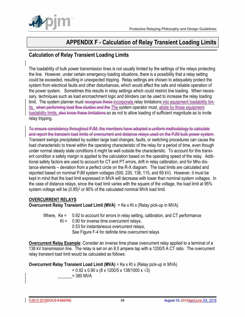
Protective Relaying Philosophy and Design Guidelines
PJM © 2018DOCS # 659765 64 August 15, 2013AprilJune XX, 2016
APPENDIX F - Calculation of Relay Transient Loading Limits
Calculation of Relay Transient Loading Limits
The loadability of bulk power transmission lines is not usually limited by the settings of the relays protecting the line. However, under certain emergency loading situations, there is a possibility that a relay setting could be exceeded, resulting in unexpected tripping. Relay settings are chosen to adequately protect the system from electrical faults and other disturbances, which would affect the safe and reliable operation of the power system. Sometimes this results in relay settings which could restrict line loading. When neces-sary, techniques such as load encroachment logic and blinders can be used to increase the relay loading limit. The system planner must recognize these incorporate relay limitations into equipment loadability lim-its. when performing load flow studies and the The system operator must abide by those equipment loadability limits, also know these limitations so as not to allow loading of sufficient magnitude as to invite relay tripping.
To ensure consistency throughout PJM, the members have adopted a uniform methodology to calculate and report the transient load limits of overcurrent and distance relays used on the PJM bulk power system. Transient swings precipitated by sudden large load changes, faults, or switching procedures can cause the load characteristic to travel within the operating characteristic of the relay for a period of time, even though under normal steady state conditions it might be well outside the characteristic. To account for this transi-ent condition a safety margin is applied to the calculation based on the operating speed of the relay. Addi-tional safety factors are used to account for CT and PT errors, drift in relay calibration, and for Mho dis-tance elements – deviation from a perfect circle on the R-X diagram. The load limits are calculated and reported based on nominal PJM system voltages (500, 230, 138, 115, and 69 kV). However, it must be kept in mind that the load limit expressed in MVA will decrease with lower than nominal system voltages. In the case of distance relays, since the load limit varies with the square of the voltage, the load limit at 95% system voltage will be (0.95)2 or 90% of the calculated nominal MVA load limit.
OVERCURRENT RELAYS Overcurrent Relay Transient Load Limit (MVA) = Ke x Kt x (Relay pick-up in MVA)
Where, Ke = 0.92 to account for errors in relay setting, calibration, and CT performance Kt = 0.90 for inverse time overcurrent relays, 0.53 for instantaneous overcurrent relays, See Figure F-4 for definite time overcurrent relays
Overcurrent Relay Example: Consider an inverse time phase overcurrent relay applied to a terminal of a 138 kV transmission line. The relay is set on an 8.0 ampere tap with a 1200/5 A CT ratio. The overcurrent relay transient load limit would be calculated as follows:
Overcurrent Relay Transient Load Limit (MVA) = Ke x Kt x (Relay pick-up in MVA)
= 0.92 x 0.90 x (8 x 1200/5 x 138/1000 x 3) = 380 MVA
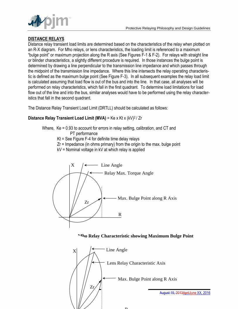
Protective Relaying Philosophy and Design Guidelines
PJM © 2018DOCS # 659765 65 August 15, 2013AprilJune XX, 2016
DISTANCE RELAYS Distance relay transient load limits are determined based on the characteristics of the relay when plotted on an R-X diagram. For Mho relays, or lens characteristics, the loading limit is referenced to a maximum “bulge point” or maximum projection along the R axis (See Figures F-1 & F-2). For relays with straight line or blinder characteristics, a slightly different procedure is required. In those instances the bulge point is determined by drawing a line perpendicular to the transmission line impedance and which passes through the midpoint of the transmission line impedance. Where this line intersects the relay operating characteris-tic is defined as the maximum bulge point (See Figure F-3). In all subsequent examples the relay load limit is calculated assuming that load flow is out of the bus and into the line. In that case, all analyses will be performed on relay characteristics, which fall in the first quadrant. To determine load limitations for load flow out of the line and into the bus, similar analyses would have to be performed using the relay character-istics that fall in the second quadrant.
The Distance Relay Transient Load Limit (DRTLL) should be calculated as follows:
Distance Relay Transient Load Limit (MVA) = Ke x Kt x (kV)2 / Zr
Where, Ke = 0.93 to account for errors in relay setting, calibration, and CT and PT performance Kt = See Figure F-4 for definite time delay relays Zr = Impedance (in ohms primary) from the origin to the max. bulge point kV = Nominal voltage in kV at which relay is applied
R
X
Max. Bulge Point along R Axis
Line Angle
Relay Max. Torque Angle
Zr
Figure F-1 Mho Relay Characteristic showing Maximum Bulge Point
R
X
Max. Bulge Point along R Axis
Line Angle
Lens Relay Characteristic Axis
Zr
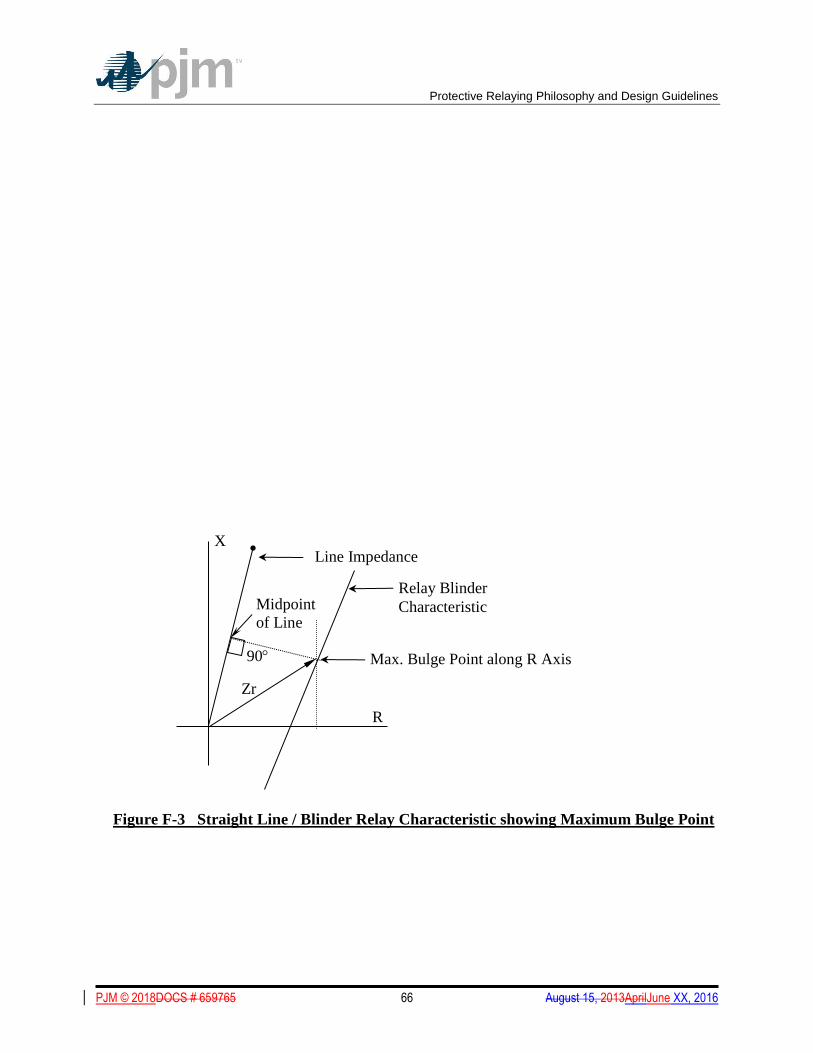
Protective Relaying Philosophy and Design Guidelines
PJM © 2018DOCS # 659765 66 August 15, 2013AprilJune XX, 2016
R
X
Max. Bulge Point along R Axis
Line Impedance
Relay Blinder
Characteristic
Zr
90
Midpoint
of Line
Figure F-3 Straight Line / Blinder Relay Characteristic showing Maximum Bulge Point
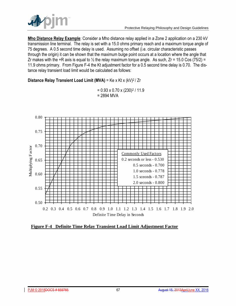
Protective Relaying Philosophy and Design Guidelines
PJM © 2018DOCS # 659765 67 August 15, 2013AprilJune XX, 2016
Mho Distance Relay Example: Consider a Mho distance relay applied in a Zone 2 application on a 230 kV transmission line terminal. The relay is set with a 15.0 ohms primary reach and a maximum torque angle of 75 degrees. A 0.5 second time delay is used. Assuming no offset (i.e. circular characteristic passes through the origin) it can be shown that the maximum bulge point occurs at a location where the angle that Zr makes with the +R axis is equal to ½ the relay maximum torque angle. As such, Zr = 15.0 Cos (75/2) = 11.9 ohms primary. From Figure F-4 the Kt adjustment factor for a 0.5 second time delay is 0.70. The dis-tance relay transient load limit would be calculated as follows:
Distance Relay Transient Load Limit (MVA) = Ke x Kt x (kV)2 / Zr
= 0.93 x 0.70 x (230)2 / 11.9 = 2894 MVA
0.50
0.55
0.60
0.65
0.70
0.75
0.80
0.2 0.3 0.4 0.5 0.6 0.7 0.8 0.9 1.0 1.1 1.2 1.3 1.4 1.5 1.6 1.7 1.8 1.9 2.0
Definite T ime Delay in Seconds
Mu
ltip
lyin
g F
acto
r
Commonly Used Factors
0.2 seconds or less - 0.530
0.5 seconds - 0.700
1.0 seconds - 0.778
1.5 sceonds - 0.787
2.0 seconds - 0.800
Figure F-4 Definite Time Relay Transient Load Limit Adjustment Factor
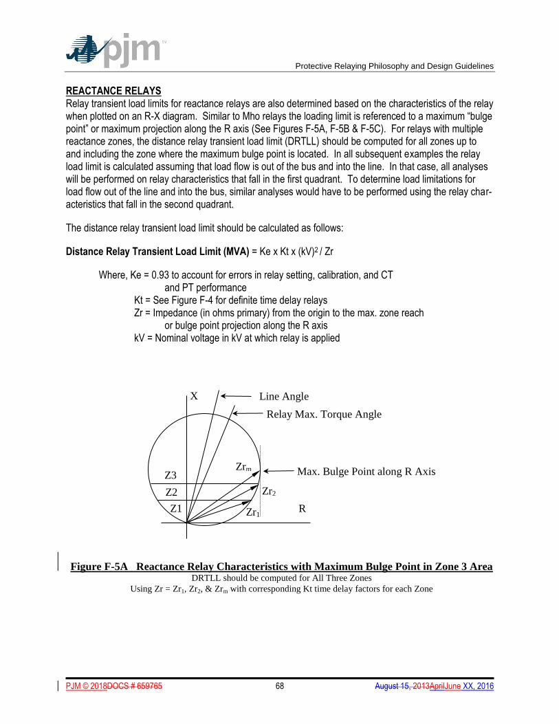
Protective Relaying Philosophy and Design Guidelines
PJM © 2018DOCS # 659765 68 August 15, 2013AprilJune XX, 2016
REACTANCE RELAYS Relay transient load limits for reactance relays are also determined based on the characteristics of the relay when plotted on an R-X diagram. Similar to Mho relays the loading limit is referenced to a maximum “bulge point” or maximum projection along the R axis (See Figures F-5A, F-5B & F-5C). For relays with multiple reactance zones, the distance relay transient load limit (DRTLL) should be computed for all zones up to and including the zone where the maximum bulge point is located. In all subsequent examples the relay load limit is calculated assuming that load flow is out of the bus and into the line. In that case, all analyses will be performed on relay characteristics that fall in the first quadrant. To determine load limitations for load flow out of the line and into the bus, similar analyses would have to be performed using the relay char-acteristics that fall in the second quadrant.
The distance relay transient load limit should be calculated as follows:
Distance Relay Transient Load Limit (MVA) = Ke x Kt x (kV)2 / Zr
Where, Ke = 0.93 to account for errors in relay setting, calibration, and CT and PT performance Kt = See Figure F-4 for definite time delay relays
Zr = Impedance (in ohms primary) from the origin to the max. zone reach or bulge point projection along the R axis
kV = Nominal voltage in kV at which relay is applied
Figure F-5A Reactance Relay Characteristics with Maximum Bulge Point in Zone 3 Area
DRTLL should be computed for All Three Zones
Using Zr = Zr1, Zr2, & Zrm with corresponding Kt time delay factors for each Zone
R
X
Max. Bulge Point along R Axis
Line Angle
Relay Max. Torque Angle
Zrm Z3
Z2
Z1 Zr1
Zr2
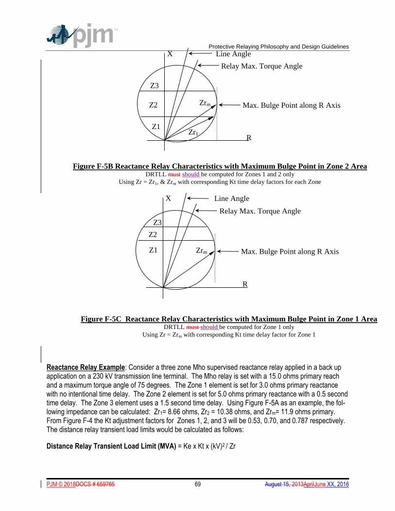
Protective Relaying Philosophy and Design Guidelines
PJM © 2018DOCS # 659765 69 August 15, 2013AprilJune XX, 2016
Reactance Relay Example: Consider a three zone Mho supervised reactance relay applied in a back up application on a 230 kV transmission line terminal. The Mho relay is set with a 15.0 ohms primary reach and a maximum torque angle of 75 degrees. The Zone 1 element is set for 3.0 ohms primary reactance with no intentional time delay. The Zone 2 element is set for 5.0 ohms primary reactance with a 0.5 second time delay. The Zone 3 element uses a 1.5 second time delay. Using Figure F-5A as an example, the fol-lowing impedance can be calculated: Zr1= 8.66 ohms, Zr2 = 10.38 ohms, and Zrm= 11.9 ohms primary. From Figure F-4 the Kt adjustment factors for Zones 1, 2, and 3 will be 0.53, 0.70, and 0.787 respectively. The distance relay transient load limits would be calculated as follows:
Distance Relay Transient Load Limit (MVA) = Ke x Kt x (kV)2 / Zr
R
X
Max. Bulge Point along R Axis
Line Angle
Relay Max. Torque Angle
Zrm
Figure F-5B Reactance Relay Characteristics with Maximum Bulge Point in Zone 2 Area DRTLL must should be computed for Zones 1 and 2 only
Using Zr = Zr1, & Zrm with corresponding Kt time delay factors for each Zone
Z3
Z2
Z1 Zr1
R
X
Max. Bulge Point along R Axis
Line Angle
Relay Max. Torque Angle
Zrm
Figure F-5C Reactance Relay Characteristics with Maximum Bulge Point in Zone 1 Area DRTLL must should be computed for Zone 1 only
Using Zr = Zrm with corresponding Kt time delay factor for Zone 1
Z3
Z2
Z1
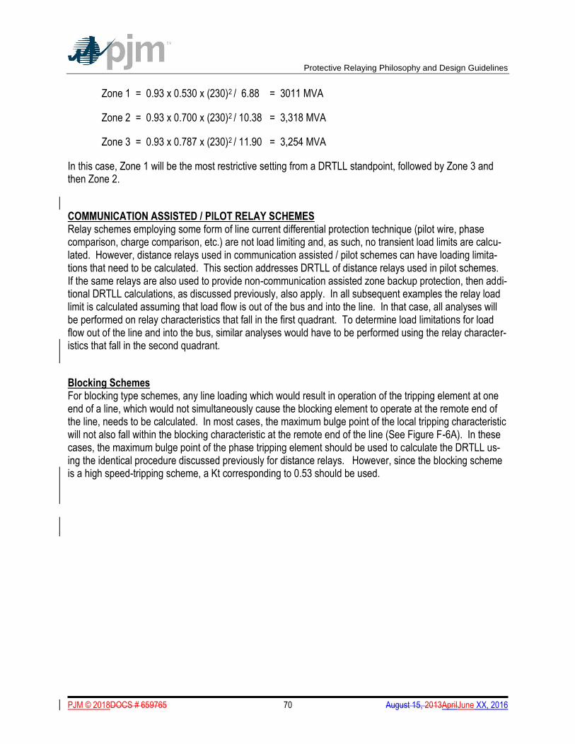
Protective Relaying Philosophy and Design Guidelines
PJM © 2018DOCS # 659765 70 August 15, 2013AprilJune XX, 2016
Zone 1 = 0.93 x 0.530 x (230)2 / 6.88 = 3011 MVA
Zone 2 = 0.93 x 0.700 x (230)2 / 10.38 = 3,318 MVA
Zone 3 = 0.93 x 0.787 x (230)2 / 11.90 = 3,254 MVA
In this case, Zone 1 will be the most restrictive setting from a DRTLL standpoint, followed by Zone 3 and then Zone 2.
COMMUNICATION ASSISTED / PILOT RELAY SCHEMES Relay schemes employing some form of line current differential protection technique (pilot wire, phase comparison, charge comparison, etc.) are not load limiting and, as such, no transient load limits are calcu-lated. However, distance relays used in communication assisted / pilot schemes can have loading limita-tions that need to be calculated. This section addresses DRTLL of distance relays used in pilot schemes. If the same relays are also used to provide non-communication assisted zone backup protection, then addi-tional DRTLL calculations, as discussed previously, also apply. In all subsequent examples the relay load limit is calculated assuming that load flow is out of the bus and into the line. In that case, all analyses will be performed on relay characteristics that fall in the first quadrant. To determine load limitations for load flow out of the line and into the bus, similar analyses would have to be performed using the relay character-istics that fall in the second quadrant.
Blocking Schemes For blocking type schemes, any line loading which would result in operation of the tripping element at one end of a line, which would not simultaneously cause the blocking element to operate at the remote end of the line, needs to be calculated. In most cases, the maximum bulge point of the local tripping characteristic will not also fall within the blocking characteristic at the remote end of the line (See Figure F-6A). In these cases, the maximum bulge point of the phase tripping element should be used to calculate the DRTLL us-ing the identical procedure discussed previously for distance relays. However, since the blocking scheme is a high speed-tripping scheme, a Kt corresponding to 0.53 should be used.
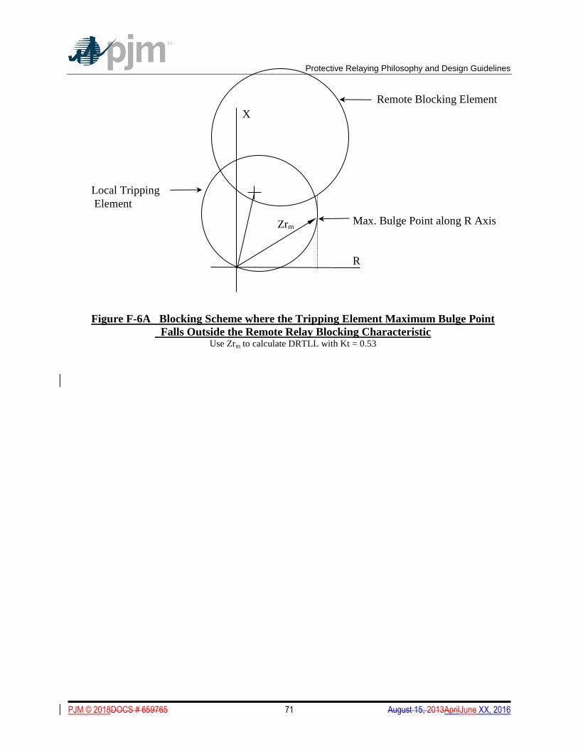
Protective Relaying Philosophy and Design Guidelines
PJM © 2018DOCS # 659765 71 August 15, 2013AprilJune XX, 2016
Figure F-6A Blocking Scheme where the Tripping Element Maximum Bulge Point
Falls Outside the Remote Relay Blocking Characteristic Use Zrm to calculate DRTLL with Kt = 0.53
R
X
Max. Bulge Point along R Axis
Remote Blocking Element
Zrm
Local Tripping
Element
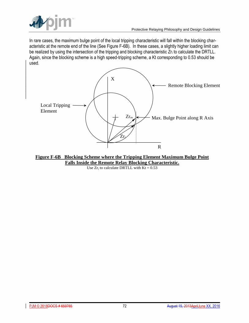
Protective Relaying Philosophy and Design Guidelines
PJM © 2018DOCS # 659765 72 August 15, 2013AprilJune XX, 2016
In rare cases, the maximum bulge point of the local tripping characteristic will fall within the blocking char-acteristic at the remote end of the line (See Figure F-6B). In these cases, a slightly higher loading limit can be realized by using the intersection of the tripping and blocking characteristic Zri to calculate the DRTLL. Again, since the blocking scheme is a high speed-tripping scheme, a Kt corresponding to 0.53 should be used.
Local Tripping
Element
Figure F-6B Blocking Scheme where the Tripping Element Maximum Bulge Point
Falls Inside the Remote Relay Blocking Characteristic. Use Zri to calculate DRTLL with Kt = 0.53
R
X
Max. Bulge Point along R Axis
Remote Blocking Element
Zrm
Zri
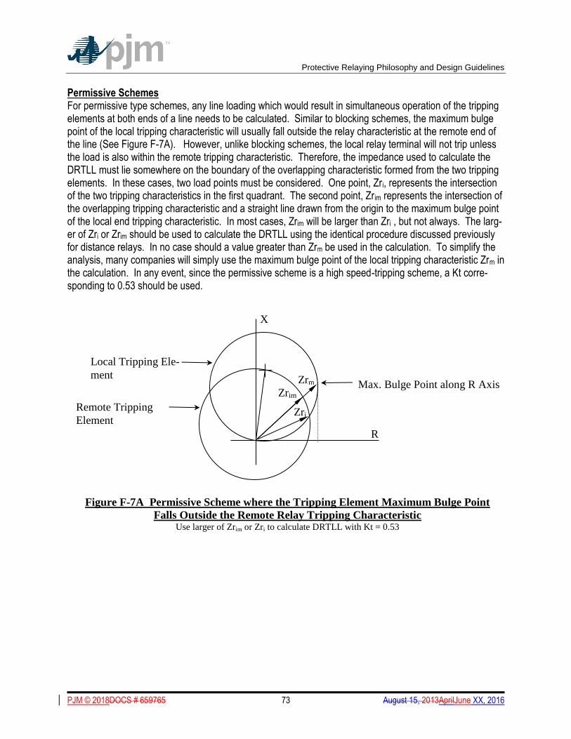
Protective Relaying Philosophy and Design Guidelines
PJM © 2018DOCS # 659765 73 August 15, 2013AprilJune XX, 2016
Permissive Schemes For permissive type schemes, any line loading which would result in simultaneous operation of the tripping elements at both ends of a line needs to be calculated. Similar to blocking schemes, the maximum bulge point of the local tripping characteristic will usually fall outside the relay characteristic at the remote end of the line (See Figure F-7A). However, unlike blocking schemes, the local relay terminal will not trip unless the load is also within the remote tripping characteristic. Therefore, the impedance used to calculate the DRTLL must lie somewhere on the boundary of the overlapping characteristic formed from the two tripping elements. In these cases, two load points must be considered. One point, Zri, represents the intersection of the two tripping characteristics in the first quadrant. The second point, Zrim represents the intersection of the overlapping tripping characteristic and a straight line drawn from the origin to the maximum bulge point of the local end tripping characteristic. In most cases, Zrim will be larger than Zri , but not always. The larg-er of Zri or Zrim should be used to calculate the DRTLL using the identical procedure discussed previously for distance relays. In no case should a value greater than Zrm be used in the calculation. To simplify the analysis, many companies will simply use the maximum bulge point of the local tripping characteristic Zrm in the calculation. In any event, since the permissive scheme is a high speed-tripping scheme, a Kt corre-sponding to 0.53 should be used.
R
X
Max. Bulge Point along R Axis
Remote Tripping
Element
Zrm
Figure F-7A Permissive Scheme where the Tripping Element Maximum Bulge Point
Falls Outside the Remote Relay Tripping Characteristic
Use larger of Zrim or Zri to calculate DRTLL with Kt = 0.53
Local Tripping Ele-
ment
Zri
Zrim
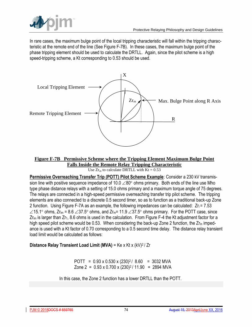
Protective Relaying Philosophy and Design Guidelines
PJM © 2018DOCS # 659765 74 August 15, 2013AprilJune XX, 2016
In rare cases, the maximum bulge point of the local tripping characteristic will fall within the tripping charac-teristic at the remote end of the line (See Figure F-7B). In these cases, the maximum bulge point of the phase tripping element should be used to calculate the DRTLL. Again, since the pilot scheme is a high speed-tripping scheme, a Kt corresponding to 0.53 should be used.
Permissive Overreaching Transfer Trip (POTT) Pilot Scheme Example: Consider a 230 kV transmis-
sion line with positive sequence impedance of 10.0 80 ohms primary. Both ends of the line use Mho type phase distance relays with a setting of 15.0 ohms primary and a maximum torque angle of 75 degrees. The relays are connected in a high-speed permissive overreaching transfer trip pilot scheme. The tripping elements are also connected to a discrete 0.5 second timer, so as to function as a traditional back-up Zone 2 function. Using Figure F-7A as an example, the following impedances can be calculated: Zri = 7.53
15.1 ohms, Zrim = 8.6 37.5 ohms, and Zrm= 11.9 37.5 ohms primary. For the POTT case, since Zrim is larger than Zr1, 8.6 ohms is used in the calculation. From Figure F-4 the Kt adjustment factor for a high speed pilot scheme would be 0.53. When considering the back-up Zone 2 function, the Zrm imped-ance is used with a Kt factor of 0.70 corresponding to a 0.5 second time delay. The distance relay transient load limit would be calculated as follows:
Distance Relay Transient Load Limit (MVA) = Ke x Kt x (kV)2 / Zr
POTT = 0.93 x 0.530 x (230)2 / 8.60 = 3032 MVA Zone 2 = 0.93 x 0.700 x (230)2 / 11.90 = 2894 MVA
In this case, the Zone 2 function has a lower DRTLL than the POTT.
R
X
Max. Bulge Point along R Axis
Remote Tripping Element
Zrm
Figure F-7B Permissive Scheme where the Tripping Element Maximum Bulge Point
Falls Inside the Remote Relay Tripping Characteristic
Use Zrm to calculate DRTLL with Kt = 0.53
Local Tripping Element
Protective Relaying Philosophy and Design Guidelines
PJM © 2018DOCS # 659765 75 August 15, 2013AprilJune XX, 2016
APPENDIX G - Voltage Transformers
Voltage Transformers
Voltage Transformers
For new line protection scheme designs:
1. Independent AC voltage sources are required for primary and back-up protection schemes if both schemes require ac potential for normal operation. Independent Voltage Transformers (VTs) are pre-ferred. Separate control cables for the secondary leads are requiredrecommended. A single set of VTs with electrically-independent secondary windings is acceptable, however it should be recognized that a VT primary failure may not only result in a fault, but will likely compromise both protection schemes. If a single set of VTs is used, it is recommended that upon detection of a loss-of-potential condition, the af-fected protection scheme(s) be automatically re-configured to protect the line using non-directional phase and ground overcurrent elements with suitable time delays. At a minimum, a ground overcurrent element should be enabled. This is considered adequate since the primary failure of a single VT nec-essarily involves ground.
2. In station configurations where a line can be supplied from multiple sources, VTs mustshould be ap-plied such that the line relays have the appropriate potential when the line is energized regardless of which source is supplying the line. For example, in a breaker-and-a-half arrangement, the VTs used for line protection must should be connected to the line position rather than to a bus.
Protective Relaying Philosophy and Design Guidelines
PJM © 2018DOCS # 659765 76 August 15, 2013AprilJune XX, 2016
APPENDIX H - Generator Protection for Units Less Than 100 MVA and Connected Below 230 kV
Generator Protection for Units Less Than 100 MVA and Connected Below 230 kV
GENERAL The protection outlined in sections 3, 4, 5 and 6 of the PJM Protective Relaying Philosophy and Design GuidelinesPJM Manual 07: PJM Protection Standards is generally applicable to all synchronous genera-tors and their connection to the utility system. However, below 100 MVA the variety of generation technolo-gies and the diverse nature of their high voltage connections to the utility system make it difficult to outline a single guideline for protection. This class of generator includes both synchronous and induction machines, inverter systems, and hybrids. These installations may exist solely to export power or they may be integrat-ed into a plant to serve local load, operating in parallel with the utility for reliability. Detailing the specific protection requirements for all of these possible combinations is beyond the scope of this appendix. The purpose of this appendix is to provide an overview of the protection philosophy and point out some pitfalls encountered in the interconnection of smaller generating plants to the utility system. Protection of the generators themselves should be designed in accordance with the generator manufacturer specifica-tions, applicable national standards, and the interconnected utility’s requirements. STANDARDS Applicable standards include, but are not limited to: ANSI/IEEE C37.101 Guide for Generator Ground Protection ANSI/IEEE C37.102 Guide for AC Generator Protection ANSI/IEEE C37.106 Guide for Abnormal Frequency Protection for Power Generating Plants ANSI/IEEE C37.95 Guide for Protective Relaying of Utility-Consumer Interconnections ANSI/IEEE C37.91 Guide for Protective Relay Applications to Power Transformers IEEE 1547 Standard for Interconnecting Distributed Resources with Electric Power Systems ZONES OF PROTECTION The protection zones of interest here can be loosely grouped into three overlapping areas: the generator, the step-up transformer and interconnection breaker, and the incoming distribution or transmission line. Protection must be provided to isolate the generator for faults in each zone. REDUNDANCY The protective system should be designed with sufficient redundancy to operate correctly for the single contingency failure of any protective relaying component. Protection provided specifically to isolate faults on the utility system, or to protect the utility from faults in the generator facility, must be fully redundant. In other words, it is required that two independent devices be able to detect and operate to clear any single contingency fault. Redundancy for generator protection, where the failure of that protection does not im-pact the utility, is only recommended.

Protective Relaying Philosophy and Design Guidelines
PJM © 2018DOCS # 659765 77 August 15, 2013AprilJune XX, 2016
SIGNAL DEPENDENT GENERATORS In general, induction generators and inverter systems are signal dependent. That is they require a connec-tion to the utility to provide excitation, or commutation, in order to generate power or to sustain fault current. When the utility opens its breaker to interrupt a fault, the connection to the generator is removed and it can no longer sustain current flow. In this manner it is self-protecting and requires very little extra protection. If the system conditions could be such that the machine can become self- excited, or if the commutation cir-cuit design will allow the inverter to sustain fault current, then the generator must be treated as if it is a syn-chronous generator and a full complement of protection is required. GENERATOR ISOLATION DEVICE All generators require a visible means of isolating the generator from the utility system. System conditions may dictate the use a three phase interrupting device to isolate the generator. Synchronous generators require a breaker for synchronizing to the utility system. The location of the generator breaker is a function of the plant design and operation. STEP-UP TRANSFORMERS Most generators will be connected to the utility system through a power transformer. The step-up trans-former reduces harmonics, lowers fault currents, and decreases the likelihood of self-excitation for induc-tion generators. While most transformer winding configurations can be used, there are protection issues that must be addressed with each different connection. WYE (grounded) -WYE (grounded) CONNECTION Protection is straight forward, but since the wye-wye connection does not provide zero sequence isolation particular care must be taken to coordinate the utility system ground relays with the genera-tor/interconnection ground protection. In certain cases the sensitivity of the utility system ground relaying may be significantly reduced. WYE (grounded) -DELTA CONNECTION The delta connection on the generator side provides zero sequence isolation between the high and low sides of the transformer. This transformer can be a significant source of ground current to faults on the utili-ty system. Depending on the system configuration, the sensitivity of the utility system ground relays may be reduced to the point where the protection is compromised. For these cases it may be advisable to ground the step up transformer neutral through a resistor. Note that the transformer has to have the proper insula-tion and terminating facilities to make this connection. For ground faults on the delta side of the transformer, the generator protection should operate to isolate the unit from the fault. Depending on the configuration of the plant bus the fault may remain energized from the high side. This will increase the phase to ground voltage by as much as 173%. It is common practice, and highly recommended that the phase to ground insulation of the bus and equipment connected to the delta side of the transformer be rated for full phase-to-phase voltage. If this is not the case, high-speed phase or 3Vo overvoltage protection should be applied that will clear the fault by opening a high side interrupting device.

Protective Relaying Philosophy and Design Guidelines
PJM © 2018DOCS # 659765 78 August 15, 2013AprilJune XX, 2016
DELTA-WYE CONNECTION The delta connection on the high side provides zero sequence isolation from the generator to ground faults on the utility system. After the utility source opens to clear the fault from the utility end, the fault may re-main energized from the generator with no ground current flow. This may increase the phase to ground voltage on the unfaulted phases by as much as 173%. Unless the phase-to-ground insulation level of the highside bus and connected equipment is rated for full phase-to-phase voltage, high-speed phase or 3Vo overvoltage protection connected on the utility side must is recommended to be applied to isolate the gen-erator from the faulted system. Direct transfer trip and/or sensitive directional power relays may also be used to augment this voltage protection. FERRORESONANCE Any delta or ungrounded wye transformer connection may be subject to ferroresonance under open phase conditions. If the system configuration is such that an open phase can create a series resonant path be-tween the transformer windings and the phase to ground capacitance then ferroresonance is possible. For this reason ungrounded wye and delta transformers should use a three phase interrupting device on the high side. Additional relaying may be required to detect and clear the resonant condition. UNDERFREQUENCY The PJM specified underfrequency set point on generators is dependent upon the PJM control zone (PJM Mid-Atlantic, PJM West, PJM ComEd or PJM South); see PJM Manual 36, 2.3.1 Generator Frequency Trip Settings for the specific setpoints. (20MW and greater) is 57.5 Hz with a 5 second time delay. Theseis setpoints is are designed to provide coordination with the utility system underfrequency load shedding scheme (UFLS). The UFLS scheme is designed to shed blocks of load in order to arrest a system frequen-cy decline caused by a mismatch between generation and load. The specified underfrequency setpoint is usually adequate to provide satisfactory turbine protection. Some units and other generating technologies may have different underfrequency limitations for which the 57.5 Hz-5 second setpoint setting may not suf-fice. If generators apply underfrequency protection that is more sensitive than the UFLS scheme, those units will trip offline at precisely the time they are needed to bolster the utility system generating capacity. Where it is possible, all generators should follow the PJM requirement for tripping at 57.5 Hz in 5 seconds. Where a generator (20 MW or greater) requires an underfrequency setting that does not coordinate with the system UFLS scheme, or a more sensitive underfrequency setting is required to detect an islanded condi-tion, PJM should be notified. UTILITY-GENERATOR INTERCONNECTION PROTECTION
Interconnection protection is applied to protect the utility system to which the generator connects from harm caused by the generating facility. These facilities will typically consist of protection to prevent island opera-tion with part of the utility system, to assure that voltage and frequency are within acceptable limits, to as-sure the generator trips for faults on the intertie line, and to assure that faults within the generating facility are isolated by the intertie breaker rather than by other interrupting devices located on the utility system. The interconnection protection may be located at a dedicated location at the point of intertie or within the generator facility. In either case, however, the associated design and setpoints for these facilities require the approval of the involved intertie utility. Test documentation is also required to assure these facilities are properly set and maintained.
Protective Relaying Philosophy and Design Guidelines
PJM © 2018DOCS # 659765 79 August 15, 2013AprilJune XX, 2016
ISLANDING In general, relaying must be installed to prevent a generator from operating inadvertently as an island. If the tie between the utility and a generator is opened there is no means of keeping the generator in synch with the utility. Depending on the system configuration, the point of separation between the two systems may not have provisions for re-synchronizing the generator prior to reestablishing the tie. Connecting the gener-ator to the utility when it is out of synchronism may have catastrophic consequences for the generator and may impact the system power quality for other utility customers. Traditionally, under/over frequency and under/over voltage protection has been applied to detect islands. Where these devices are not sufficient to detect all the load/generation conditions for possible islands, supplemental anti-islanding protection (e.g. a rapid change in power factor or transfer trip from the utility supply should be applied). Direct transfer trip (DTT) requirements may vary depending on the nature of the system of the intertie utility, specific design parameters of the generating station, and the ratio of minimum load connected to the inter-tie line to the total generation on the line. In general, the need for DTT facilities must be determined on specifics of an individual installation. Typically, larger units (5 MW and above) are probable candidates for the need for DTT. Automatic reclosing on the intertie line may need to be delayed, or supervised by voltage sensing relays, in order to ensure that the generator is disconnected before auto-reclosing takes place.
INTERTIE LINE FAULT PROTECTION Protection must be provided to rapidly isolate the generator from the utility system for all types of faults, anywhere on the intertie line. Protection settings must take into account the effects of infeed from other generators that may be connected to the line. Protection for multi-phase faults is generally provided by voltage controlled time overcurrent, or impedance relaying with an appropriate coordination timer. Three single-phase undervoltage relays may be used if ad-equate sensitivity can be maintained for line faults without sacrificing coordination for faults on other feed-ers supplied from the same bus. Open phase protection utilizing a negative sequence time overcurrent, or transformer neutral time overcurrent relay should be applied if loading is such that an unbalance can over-load the utility transformer. Protection for ground faults on the intertie line varies depending on the generator step-up transformer con-nection. Wye (grounded) –wye (grounded) connected transformers provide no isolation for zero sequence current between the generator and the utility. Protection can be provided by a neutral time overcurrent relay on either the generator or the transformer. Three single phase undervoltage relays may also be used if ad-equate sensitivity and coordination can be achieved. For wye (grounded) -delta connected transformers (delta on the generator side), the transformer is a source of zero sequence current for ground faults on the utility system. Protection for ground faults is gen-erally provided by a ground time overcurrent relay on the transformer neutral. For transformer connections with an ungrounded winding on the utility system side, such as delta-wye and delta-delta connected transformers, the generator is isolated from the utility for ground faults on the intertie line. The transformer is not a source of ground current for this fault. Unless detected, a ground fault will re-main energized from the generator. Voltage on the faulted phase will be reduced, but voltage on the un-
Protective Relaying Philosophy and Design Guidelines
PJM © 2018DOCS # 659765 80 August 15, 2013AprilJune XX, 2016
faulted phases may increase to 173% of nominal. This extreme overvoltage, can cause catastrophic failure of surge arresters and lead to other equipment insulation failures. This condition must be detected and re-moved rapidly (usually within 0.16 seconds based on typical arrester transient overvoltage (TOV) ratings). Protection for this condition is required (Fig 7A PJM Manual 14A) and may consist of three single phase overvoltage relays, or a 3Vo overvoltage relay, connected to phase-to-ground voltage transformers on the utility side of the transformer. As an alternative, a combination of a high-speed overvoltage and an un-dervoltage relay connected to a single phase may be used. However, because of the high speed with which this scheme must operate, the undervoltage relay may be prone to nuisance tripping. If the phase-to-ground insulation of the faulted system is rated for full phase-to-phase voltage, a high speed scheme is not required. For this case, time delayed protection, such as directional power relays, may also be used. In addition to the protection listed above, the protection applied for anti-islanding, time delayed phase over/under voltage relays and sensitive definite time over and under frequency relays, provide a use-ful form of back-up intertie line fault protection. SYSTEM PROTECTION FOR GENERATOR FACILITY FAULTS The generator facility encompasses all of the equipment from the utility intertie line connection point to the generator. Protection should be applied to detect and clear any fault within the generator facility. These devices must be set to coordinate with the utility protection to assure isolation of only the faulted zone. Specific requirements depend on the electrical arrangement of the plant, but can generally be grouped into three areas: the primary bus; the step up transformer; and the low side bus. Protection of the primary bus, that is the zone encompassing the utility interconnection device through the step-up transformer bushings, may be via bus differential relays, phase and ground time delayed and in-stantaneous overcurrent relays, or power fuses. If overcurrent relays are used, they may need to be made directional so as to properly coordinate with both up-stream and down-stream devices. Power fuses are not recommended for installations 10 MVA or greater, or where delta or ungrounded wye connected trans-formers are used due to the potential for overvoltage and ferroresonance problems. Protection of the step-up transformer may be provided by the primary bus overcurrent devices, if they have sufficient sensitivity. More likely, this protection will be provided by dedicated overcurrent relays installed in the transformer high side bushing current transformers. For transformers 10 MVA and greater, a more sensitive method of detecting internal faults (i.e. transformer differential or sudden pressure relay) is rec-ommended. The most complete protection package would combine a transformer differential with a fault pressure relay to detect low magnitude turn-to-turn faults. On grounded wye transformers, a more sensitive ground overcurrent relay can be installed on the transformer neutral to protect the grounded winding. Faults on the low side bus must be isolated from both the utility side and the generator side. Protection for this zone is generally provided by phase and ground overcurrent relays. This protection should operate a high side breaker to isolate the fault from the utility. For transformer connections with a delta on the genera-tor side, zero sequence overvoltage protection may be used to detect and trip the high side for ground faults. GENERATOR PROTECTION

Protective Relaying Philosophy and Design Guidelines
PJM © 2018DOCS # 659765 81 August 15, 2013AprilJune XX, 2016
Generator protection is the responsibility of the IPP. Good protection practices for small generating facili-ties vary considerably with size and type of generation. Protection must be provided to comply with all ap-plicable ANSI/IEEE Standards.
Protective Relaying Philosophy and Design Guidelines
PJM © 2018DOCS # 659765 82 August 15, 2013AprilJune XX, 2016
APPENDIX I - Accepted PJM Bulk PowerAcceptable Three Terminal Line Applications
Refer to M07. No supplementary information available Accepted PJM Bulk Power Three Termi-nal Line Applications
This appendix outlines the categories of three terminal line applications and associated protection require-
ments which have been deemed acceptable for use within PJM. Three terminal line applications are only permitted at voltages less than 300 kV when the requirements listed below are met. No three terminal line applications are permitted on systems at 300 kV and above.
CATEGORY I – TEMPORARY INSTALLATION This category applies when an acceptable long-term reinforcement was already identified but cannot be installed in time and consequently the reliability of the transmission system may be compromised. Exam-
ples include construction delays, unusual combinations of system demand and long term transmission equipment forced outages. The three terminal line configuration mustmust be removed when the planned permanent reinforcement is in place.
The following requirements apply to Category I temporary installations:
1.1 Protection Requirements
A detailed relay coordination review mustmust be performed which establishes that the planned addition will result in no compromises to coordination. The review should include consideration of apparent impedances at each terminal, weak sources, fault current nulls or outflows.
The protection scheme(s) mustmust be designed to provide high-speed (pilot) clearing of faults at all locations on the three terminal line.
Backup protection mustmust be provided and applied such that for faults anywhere on the circuit, each terminal should be able to detect the fault and initiate tripping without regard to whether the other terminals have opened or are still closed.
The backup line protection may be pilot (high-speed, communications dependent) or non-pilot (stepped-distance, ground time overcurrent) depending on the specific circumstances and results of fault
and stability studies, etc. Each affected Transmission Owner will evaluate the proposed installations on a case-by-case basis. If a backup high-speed pilot scheme is requiredrequired, the requirements for dual pi-lot channels outlined in Appendix E of this document mustmust be met.
Designing for sequential clearing of faults is not acceptable in either of the primary or backup protection schemes.

Protective Relaying Philosophy and Design Guidelines
PJM © 2018DOCS # 659765 83 August 15, 2013AprilJune XX, 2016
2.0 Category II – Permanent Installation
Three-terminal lines may be considered for long term installation on the PJM system when a sub-
station site at the proposed three terminal tap point is deemed unnecessary by PJM, cost prohibitive, envi-ronmentally unacceptable, or requires condemnation proceedings.
Considerations on the necessity of a substation site at the proposed three terminal tap point should
include an assessment of the impact of the potential three terminal line on meeting the PJM planning crite-ria (loadflow and stability) and on the daily system operating flexibility.
The following requirements apply to Category II permanent three terminal line installations:
2.1 Protection Requirements
A detailed relay coordination review mustmust be performed which establishes that the planned addition will result in no compromises to coordination. The review should include consideration of apparent impedances at each terminal, weak sources, fault current nulls or outflows.
The protection scheme(s) mustmust be designed to provide high-speed (pilot) clearing of faults at all locations on the three terminal line.
Backup relays mustmust be provided and applied such that for faults anywhere on the cir-cuit, each terminal should be able to detect the fault and initiate tripping without regard to whether the other terminals have opened or are still closed.
The backup line protection may be pilot (high-speed, communications dependent) or non-pilot (stepped-distance, ground time overcurrent) depending on the specific circumstances and results of fault and stability studies, etc. Each affected Transmission Owner will evaluate the proposed installations on a case-by-case basis. If a backup high-speed pilot scheme is requiredrequired, the requirements for dual pilot channels outlined in Appendix E of this document mustmust be met.
For reliability reasons, extending an existing two-terminal directional comparison blocking or unblocking scheme operating over power line carrier to a third terminal is not acceptable for primary or backup line protection.
In all cases where a pilot scheme is requiredrequired, digital communications channels be-
tween the three terminals mustmust be used. No portions of these channels may be metallic (i.e. telephone cable, coaxial cable, etc) other than between relays and multiplex equipment (where used) within the con-
trol house. External audio-tone interfaces are not acceptable. Where multiplexing schemes are use, they mustmust be evaluated with respect to the characteristics of the proposed protection (i.e. susceptibility to mal-operation due to variances in path delay) on a case-by-case basis.
Designing for sequential clearing of faults is not acceptable in either of the primary or backup protection schemes.
Protective Relaying Philosophy and Design Guidelines
PJM © 2018DOCS # 659765 84 August 15, 2013AprilJune XX, 2016
APPENDIX J - Requirements for the Application of Triggered Fault Current Limiters
Requirements for the Application of Triggered Fault Current Limiters
The following document This appendix describes the concerns and lists the requirementsrecommenda-tions for the application of triggered fault current limiters (FCL’s) when proposed for the mitigation of in-creased fault current availability at a utility distribution bus resulting from the installation of new equipment or rearrangement of existing equipment at a non-utility station. Note: in the context of this document, “utility” means the delivery, or “wires” company whose equipment is being affected by the addition of the new equipment or rearrangement of existing equipment. Please note there are no formal PJM requirements for Triggered Fault Current Limiters. General The installation of new equipment or rearrangement of existing equipment at a non-utility station can result in an increase in fault current at the utility bus to a point beyond the momentary current withstand capability or the interrupting capability (or both) of one or more circuit breakers or other equipment connected to the utility bus. Possible solutions to this problem include the replacement of the underrated equipment, the in-stallation of reactors, splitting buses that were formerly “solid”, etc. Recently a technique has been proposed involving the use of FCL’s, which can be described as “smart fus-es”. If properly applied, the device will carry the required load current and yet operate very quickly to inter-rupt the fault current contribution from the new equipment, thereby limiting the fault current at the station bus to safe levels. The design of the FCL includes sensing and firing logic, a heavy copper bar fitted with explosive charges, and a current-limiting fuse in parallel with the copper bar. When the sensing logic de-tects a fault above its threshold setting, it fires the explosive charges to cut the copper bar, diverting all cur-rent through the fuse, which clears the fault very quickly. Depending on how fast the FCL is able to sense the fault and operate, the instantaneous fault current peak at the utility bus may be no higher than it would have been without the generators having been connected. There are, however, a number of concerns surrounding the application of FCL’s. The remainder of this dis-cussion presents those concerns and lists requirements relating thereto. APPLICATION CONCERNS AND REQUIREMENTS Application Concerns and Recommendations Selectivity When a fault occurs on utility equipment and this fault causes the current through the FCL to exceed the threshold value, the FCL will be triggered in order to reduce the total fault current. The FCL may also be triggered for faults within the FCL owner’s system. Both of these situations will result in the likelihood of “non-selective tripping”, meaning that more power system elements were removed from service than would otherwise have been necessary to clear the original fault. To the extent that this lost equipment is important
Protective Relaying Philosophy and Design Guidelines
PJM © 2018DOCS # 659765 85 August 15, 2013AprilJune XX, 2016
to the system, the system is degraded. The amount of time that the degradation will be in effect is a func-tion of how long it will take the FCL owner to replace the expended parts of the affected FCL’s. RequirementsRecommendations: All concerned parties must understand the exposure of the FCL to a range of faults on the utility system and to faults within the FCL owner’s system which can result in operation of the FCL, and must should for-mally agree that the loss of equipment resulting from the operation of the FCL for those faults is an ac-ceptable consequence. Proof of Ddesign Aadequacy When a fault occurs on the utility system that, with the added contribution from the new equipment, ex-ceeds the momentary rating or the interrupting rating of the utility breaker or other equipment, there is a concern that the FCL design and application may not operate sufficiently fast to protect the utility equip-ment. Requirements Recommendations: The FCL owner is expected to must provide detailed calculations demonstrating that the fault current limit-er will achieve its intended purpose of protecting the utility equipment from being subjected to current be-yond its capability. The calculations must include the anticipated current-versus time waveforms of the total asymmetrical current flowing through the utility equipment for the maximum fault and minimum fault that will operate the FCL. The maximum current should be the maximum asymmetrical current available based on the calculated X/R ratio, and should include both the contributions from the system as well as the let-through contribution from the FCL. Detailed waveform analysis may become unnecessary if the calculation method used is sufficiently conservative (i.e. the arithmetic addition of the FCL peak let-through current and the system peak asymmetrical current). The calculations will require modeling of the utility system and the FCL owner’s system, and must should include the transient effects of induction and synchronous motors. Since the FCL will not operate for fault level values below its threshold, the RMS value of the threshold of the FCL should be added to the short circuit current of the breaker for determination of interrupting duty.
The utility mustshould supply the FCL owner with sufficient modeling information of the utility sys-tem to allow the FCL owner to make the analysis described in 2.2.2.1. described in the preceding paragraph. The FCL owner mustshould provide design information showing that the operation of the FCL will not be compromised under low AC voltage conditions at the FCL owner’s facility resulting from any fault on the utility system requiring the FCL to operate.
Changes to the Eelectrical sSystem Changes to the FCL owner’s electrical system may render the FCL application incapable of performing its originally-intended function.

Protective Relaying Philosophy and Design Guidelines
PJM © 2018DOCS # 659765 86 August 15, 2013AprilJune XX, 2016
RequirementsRecommendations: If changes are made to the FCL owner’s electrical system, the FCL owner must should re-apply the requirements analysis outlined in section 2.2. in the section titled Proof of Design Adequacy and associated subsections and provide documentation of this analysis to the utility for review.
Redundancy If the FCL, for some reason, fails to operate as intended, a fault on the utility may result in a catastrophic failure. It should be emphasized that this concern is not equivalent to concern for a stuck breaker or a failed relay. A failure of the FCL to operate when required is a substation safety hazard, especially in a situation where an operator may unknowingly be closing a breaker into a fault. Further, a catastrophic breaker failure may cause significant collateral damage to other equipment in the utility substation.
RequirementsRecommendations: The FCL owner mustshould provide design information showing that for the single-contingency failure of the FCL to perform its intended function, the overall intent of protecting the utility equipment from overduty conditions is still met.
FCL Bbypass Aarrangements The FCL may undesirably be electrically bypassed by the owner.
RequirementsRecommendations: The FCL owner should have a written procedure which prohibits bypassing the FCL unless it is demon-strated to the satisfaction of the utility that conditions do not require the potential operation of the FCL.
Maintenance and Ttesting If the FCL is not tested and maintained properly, it may not be capable of operation when required.
RequirementsRecommendations: Routine testing of FCL trigger levels, firing logic, and firing circuitry mustshould be conducted at least every four years. Documentation of this testing should be available upon request by the utility. The utili-ty should be granted physical access to inspect the FCL as deemed necessary by the utility.
Reference: “Limitations of Fault-Current Limiters for Expansion of Electrical Distribution Systems”, J. C. Das, IEEE Transactions on Industry Applications, Vol. 33, No. 4, July/August 1997.