Embed Size (px)
Citation preview

Proposed Guidance Implementation of 316(b) – Regulating Cooling Water Intake Structures Department staff have created draft guidance intended for permittees and permit drafters to use when making best technology available (BTA) determinations according to new federal regulations on cooling water intake structures. This draft guidance is now available for external review and comment. In October 2014, the USEPA promulgated regulations for cooling water intake structures at existing facilities. The Department already has the authority to regulate cooling water intake structures under s. 283.31(6), Stats., which states that the Department may require the use of the best technology available (BTA) for minimizing adverse environmental impact. However, there are currently no state administrative rules that require the implementation of specific federal standards for new or existing facilities. Department staff are drafting proposed rule language (WY-19-14) to incorporate USEPA requirements into Wisconsin’s code. If adopted, this proposed rule might become effective in 2018. Since permits must be written to incorporate requirements from the USEPA regulations that are already in effect, guidance is necessary in the interim until state rules can be adopted in order to help staff make BTA determinations that are in compliance with the USEPA rule. USEPA’s 2014 rule provides compliance options and specifies criteria that the Department must consider when making BTA determinations. The USEPA rule also requires that permittees submit certain application materials to be used when making BTA determinations. The draft guidance attempts to explain these regulations and provide advice to staff reviewing permit application materials, making BTA determinations, and writing permit and fact sheet language to incorporate these rules. The Department is now asking for input from external stakeholders on this draft guidance. Once the comment period is complete, all comments will be considered, revisions will be made to the guidance as needed, and final guidance will be made available to internal and external stakeholders. Comments related to this draft guidance should be sent to Jason Knutson at [email protected].

BUREAU OF WATER QUALITY PROGRAM GUIDANCE
Wastewater Policy and Management Team
Guidance for Implementation of Section 316(b) of the Clean Water Act: Regulating Cooling Water Intake Structures
11/10/2016
Guidance Number: 3400-2016-0X
Wisconsin Department of Natural Resources 101 S. Webster Street, P.O. Box 7921, Madison, WI
53707-7921
This document is intended solely as guidance, and does not contain any mandatory requirements except where requirements found in statute or administrative rule are referenced. This guidance does not establish or affect legal rights or obligations, and is not finally determinative of any of the issues addressed. This guidance does not create any rights enforceable by any party in litigation with the State of Wisconsin or the Department of Natural Resources. Any regulatory decisions made by the Department of Natural Resources in any matter addressed by this guidance will be made by applying the governing statutes and administrative rules to the relevant facts.
APPROVED: _________ __________ _____________ Sharon L Gayan, Director Date Bureau of Water Quality

Guidance for Implementation of Section 316(b) DRAFT November 2016
1 | P a g e
Contents 1. Additional and Clarified Definitions ....................................................................................................................................................... 2
2. Introduction ........................................................................................................................................................................................... 3
History of Federal 316(b) Regulations ................................................................................................................................................... 4
Figure 1. Section 316(b) Timeline .......................................................................................................................................................... 6
3. Implementation of USEPA’s 2001 New Facilities Rule ........................................................................................................................... 7
Figure 2. BTA Determination Flowchart: New Facilities ........................................................................................................................ 9
3.1 Application Materials required for Track I Facilities ...................................................................................................................... 10
3.2 Application Materials for Track II facilities .................................................................................................................................... 11
Figure 3. Application Materials Required For New Facilities ............................................................................................................... 14
4. Implementation of USEPA’s 2014 Existing Facilities Rule .................................................................................................................... 15
4.1 Timeline for Submittal of Application Materials for Existing Facilities .......................................................................................... 15
Figure 4. Timelines for Facilities > 2 MGD & < 125 .............................................................................................................................. 17
Figure 5. Timelines for Facilities > 125 MGD ....................................................................................................................................... 18
4.2 Application Materials Required For Existing Facilities ................................................................................................................... 19
Figure 6. Application Materials Required For Existing Facilities .......................................................................................................... 35
4.3 Application Review and BTA Determination Process .................................................................................................................... 36
4.4 Making BTA Determinations for Facilities > 2 MGD & > 25% Used for Cooling ............................................................................ 37
4.4.1 Impingement Mortality BTA – Determination and Compliance ............................................................................................. 37
4.4.2 Entrainment BTA – Determination and Compliance .............................................................................................................. 47
Figure 7. Finding the “Sweet Spot” With Variable Frequency Drives .................................................................................................. 52
4.5 Making BTA Determinations for New Units at Existing Facilities .................................................................................................. 61
Monitoring Requirements for New Units ........................................................................................................................................ 63
4.6 Making BTA Determinations Using Best Professional Judgment................................................................................................... 64
5. General FAQ ......................................................................................................................................................................................... 67
6. References ........................................................................................................................................................................................... 69
Appendix A: Map of Facilities ................................................................................................................................................................. 70
Appendix B: Template Permit Language for BTA Determinations (>2MGD DIF and >25% of intake water used for cooling) ............ 71
WPDES Permit Template for Section 1 - “Cooling Water Intake Requirements” ................................................................................ 71
WPDES Fact Sheet Template for Section 1 - “Cooling Water Intake Requirements” For Interim/Best Professional Judgment BTA Determinations .................................................................................................................................................................................... 77
WPDES Fact Sheet Template for Section 1 - “Cooling Water Intake Requirements” For Final BTA Determinations made under 40 CFR 125.90-98 ...................................................................................................................................................................................... 82
Appendix C: Compliance Schedule Template for Installation of BTA(s) ................................................................................................ 90

Guidance for Implementation of Section 316(b) DRAFT November 2016
2 | P a g e
1. Additional and Clarified Definitions
See 40 CFR 125.92 for definitions used in the federal rule. The purpose of this section is to define additional terms and clarify ambiguous definitions for implementation of the rule in Wisconsin.
All life stages of fish and shellfish: eggs, larvae, juveniles, and adults. It does not include life stages of fish and shellfish specifically identified as nuisance species.
BTA: the best technology available for minimizing adverse environmental impact associated with a cooling water intake structure.
Capacity Utilization Rate (CUR): CUR refers to the percent of energy generation capacity used over a 24 month block contiguous period preceding permit reissuance. Low CUR can be used as an exemption to the requirement to install impingement mortality BTA (40 CFR 125.94 (c)(12)). However, in considering requests for use of this exemption, the Department will also consider whether or not water is withdrawn during periods of shutdown. This is because, even if a facility has a low CUR by definition, it may operate its pumps continuously, thereby causing no reduction in impingement. The Department realizes that some water flow may be necessary even during shutdown and will for that reason also consider requests where the intake velocity is reduced to below 0.25 fps during shutdown periods through use of variable speed pumps or other flow reduction measures.
De minimis: A determination, based on a review of data submitted under § 122.21(r), that the documented rate of impingement at the cooling water intake structures is so low that no additional controls are warranted (see 40 CFR 125.94 (c) (11)).
Hydraulic Zone of Influence: the portion of the source waterbody hydraulically affected by the cooling water intake structure. This is also referred to as the “area of influence.” Flow nets may be helpful in delineating the zone of influence.
Maximum design inlet velocity: The value assigned during the cooling water intake structure design to the maximum instantaneous speed at which the cooling system is capable of withdrawing water through the intake screen or inlet, from a source waterbody. It shall be applied at the point at which water is withdrawn from waters of the state and shall be calculated using the following equation:
𝑉 =𝑄
𝐴 ∗ 𝑃
Where V = the maximum design inlet velocity, Q = the maximum volumetric flow rate based on pump capacities (excluding emergency and redundant pumps), A = typical wetted area of the screen at Q7,10 flows, and P = screen open area percentage divided by 100. Nuisance Species: Includes Common Carp (Cyprinus carpio), Grass Carp (Ctenopharyngodon idella), Silver Carp (Hypophthalmichthys molitrix), Bighead Carp (Aristichthys nobilis), Black Carp (Mylopharyngodon piceus), Goldfish (Carassius auratus), Sea Lamprey (Petromyzon marinus), Threespine Stickleback (Gasterosteus aculeatus), Ruffe (Gymnocephalus cernuus), Tubenose Goby (Proterorhinus marmoratus), Round Goby (Apollonia melanostomus), Rusty Crayfish (Orocnectes rusticus), Red Swamp Crayfish (Procambarus clarkii), the shellfish species listed in ss. NR 40.04 (2) (d) and NR 40.05 (2) (d), and any species subsequently added by the Department. It also includes Alewife (Alosa pseudoharengus), Rainbow smelt (Osmerus mordax), and White Perch (Morone americana) in inland waters as well as species designated by the Department as detrimental in the waters specified in s. NR 20.38. Threatened and Endangered Species: Clarification – where the rule provides protections for federally-listed T&E species, the permit drafter should give similar consideration for state-listed T&E species listed in s. NR 27.03, Wis. Adm. Code. Vicinity of the Intake: A region around the intake, typically broader than the hydraulic zone of influence, including areas which species susceptible to impingement or entrainment use as habitat.

Guidance for Implementation of Section 316(b) DRAFT November 2016
3 | P a g e
2. Introduction
The Clean Water Act (CWA) was first enacted in 1972 and introduced the National Pollutant Discharge Elimination System (NPDES) permit program. The CWA included section 316(b), the only portion that addresses the condition of water withdrawn from a receiving water rather than that discharged into a receiving water. Facilities with NPDES permits are subject to 316(b), which requires that the location, design, construction, and capacity of cooling water intake structures reflect the best technology available for minimizing adverse environmental impact. Cooling water intakes can cause adverse environmental impacts such as entrainment mortality - pulling early life stage fish and shellfish through the cooling water system, where the organisms are harmed by heat, pressure, mechanical stress, and chemicals used in the system. Larger organisms can also be killed when they are trapped against screens at the entrance to an intake structure, otherwise known as impingement mortality.
The purpose of this guidance document is to help Wisconsin Department of Natural Resources (Department) staff make decisions as to whether proposed or existing intake structures and associated technologies meet best technology available (BTA) requirements and to help permittees determine what steps they need to take to come into compliance. This document relies on past experience, EPA rules and guidance, and other reference materials to provide advice on how to perform site-specific evaluations of cooling water intake structures. This guidance may be updated as Department staff learn more about 316(b) rules or as other program needs dictate.
Previous Department guidance was provided in “Guidance for Evaluating Cooling Water Intake Structures” (2005) and “Guidance for Evaluating Intake Structures Using Best Professional Judgment” (2009). The guidance provided here is intended to replace these and all other previously written Department guidance related to 316(b).
Guidance Authors:
• Jason Knutson, Wastewater Section • Curt Nickels, South District-East • Kari Fleming, Permits Section • Tim Simonson, Fisheries Management • Paul Luebke, Wastewater Section • Jacob Zimmerman, South District-Central
For more information about this guidance, or 316(b) in general, contact the statewide 316(b) Program Coordinator:
Jason Knutson Wastewater Engineer Bureau of Water Quality [email protected] (608) 267-7894

Guidance for Implementation of Section 316(b) DRAFT November 2016
4 | P a g e
History of Federal 316(b) Regulations The United States Environmental Protection Agency (EPA) first promulgated regulations to implement section 316(b) in 1976. A group of utilities challenged the initial rules in 1977, and, without reaching the merits of the regulations, the U.S. Court of Appeals for the Fourth Circuit sent the rules back to EPA (Appalachian Power Co. V. Train, 566 F.2d 451; 4th Cir. 1977). The agency later withdrew the remanded portion of the rules, keeping the section that requires BTA determinations (now 40 CFR 401.14), and published draft guidance that directed permitting authorities to determine BTA for each facility using best professional judgment on a case-by-case basis. (Evaluating the Adverse Impact of Cooling Water Intake Structures on the Aquatic Environment: Section 316(b); US EPA 1977). In Wisconsin, statutory language was written into section s. 283.31(6), Wis. Stats., that linked the Department’s authority to regulate intake structures with the issuance of Wisconsin Pollutant Discharge Elimination System (WPDES) permits: “Any permit issued by the department under this chapter which by its terms limits the discharge of one or more pollutants into the waters of the state may require that the location, design, construction and capacity of water intake structures reflect the best technology available for minimizing adverse environmental impact.” (note: this applies to all cooling water intake structures – not just cooling water intake structures) In 1993, the environmental group Riverkeeper filed a lawsuit to force EPA to adopt specific rules in accordance with section 316(b). EPA entered into a consent decree in 1995 that set a schedule for taking action on regulations to implement section 316(b) in three phases. In 2001, EPA published the so-called “Phase I” rule which applies to new facilities. This rule establishes a two-track approach which requires closed-cycle cooling for new facilities or a demonstration that a new facility can achieve flow rates commensurate with closed-cycle cooling (see “Implementation of the 2001 New Facilities Rule”, page 7, below). In 2004 the U.S. Court of Appeals for the Second Circuit upheld most of the rule, rejecting only those provisions that allowed a demonstration of aquatic habitat restoration measures to meet the BTA requirements of the rule (Riverkeeper, Inc. v. US EPA, 358 F.3d 174; 2d Cir. 2004). Also in 2004, EPA published the “Phase II” rule, which applied to existing power plants with design intake flows (DIF) greater than 50 million gallons per day (MGD) (69 FR 41576; July 9, 2004). The Department began evaluating intake structures at facilities that were subject to this rule (power plants > 50 MGD) as individual WPDES permits were reissued. The Phase II rule required these permittees to evaluate conditions in the source water where their intake was located, compare impingement and entrainment potential at the intake structure to baseline conditions, and determine whether existing technology was sufficient or if something different was needed to meet BTA standards. The performance standards in the Phase II rule consisted of ranges of reductions of impingement mortality and, where applicable, entrainment (i.e., reduce impingement mortality by 80 – 95% and/or entrainment by 60 – 90%, relative to baseline conditions). These performance standards were not based on a single technology, but rather on consideration of a suite of technologies that EPA determined were commercially available and economically achievable for the industries affected as a whole. The Phase II rule identified a number of alternative ways facilities could meet the performance standards. Among the alternatives were provisions allowing a facility to demonstrate that the cost of compliance for a particular facility would be significantly greater than the costs considered by EPA in establishing the applicable performance standards (the cost-cost alternative). A facility could also demonstrate that the cost of compliance would be significantly greater than the environmental benefits of complying with the standard (the cost-benefit alternative).

Guidance for Implementation of Section 316(b) DRAFT November 2016
5 | P a g e
Following a legal challenge in 2007, the U.S. Second Circuit Court of Appeals sent back numerous parts of the Phase II rule to EPA (Riverkeeper v. US EPA, 475 F.3d 83; 2d Cir. 2007). Parts of the rule that were remanded included EPA's determination of BTA, the rule's performance standard ranges, and the cost-cost and cost-benefit alternatives. Consistent with the earlier Phase I court decision, the Second Circuit also rejected “restoration” as a technology for BTA. After the remand, on July 9, 2007, EPA suspended the entire Phase II rule, with the exception of section 125.90(b), which directed states to address 316(b) requirements on a case-by-case, best professional judgment basis. Included in the Second Circuit’s decision was a rejection of EPA’s determination to not classify closed-cycle cooling as BTA for existing facilities. EPA said it had justified its decision in part based on cost-benefit considerations; the Second Circuit concluded that comparing costs and benefits was not a proper factor to consider in determining BTA. Several industry group litigants petitioned the US Supreme Court to hear an appeal of the Second Circuit’s decision. In April 2009, the Supreme Court ruled in Entergy Corp. v. Riverkeeper Inc., 556 U.S. 208 (2009), that it is permissible to consider costs and benefits in determining BTA to minimize adverse environmental impacts under section 316(b). The Supreme Court then sent the rule back to the Second Circuit and EPA asked that the entire rule, not just the remanded portions, be remanded to EPA for further review. (See http://water.epa.gov/lawsregs/lawsguidance/cwa/316b/rules.cfm for more information.)
In 2006, while all the court debate was going on around the Phase II rules, EPA also published their “Phase III” rule with requirements for new offshore oil and gas extraction facilities and all other existing facilities (i.e., power plants with DIF < 50 MGD and all manufacturing facilities) (71 FR 35006; June 16, 2006). The Phase III rule stated that in the case of existing facilities, states had to determine BTA using best professional judgment on a case-by-case basis. A number of parties filed petitions for review of the Phase III rules. In 2009, EPA petitioned the 5th Circuit Court of Appeals to remand to EPA those parts of the rule that applied to existing facilities. In 2010, the 5th Circuit U.S. Court of Appeals upheld the portions of the Phase III rules that applied to offshore oil and gas facilities. The Court granted EPA’s request to remand the existing facility portions to EPA for further review (ConocoPhillips Co. v. US EPA, 612 F.3d 822; 5th Cir. 2010). The Court noted that the EPA’s case-by-case, best professional judgment permitting procedure would remain in place while EPA reviewed the existing facility portions of the Phase II and Phase III rules.
After the Phase II and Phase III federal rules were remanded and withdrawn, EPA stated that all existing facilities (regardless of size or location) still had to be evaluated for 316(b) compliance at each permit reissuance. Without the specific standards previously provided in Phase II and Phase III, Wisconsin and other states were required to make BTA determinations using their best professional judgment, until new existing facility rules could be promulgated by EPA.
In 2014, EPA completed a new final rule to establish requirements under section 316(b) for all existing facilities that withdraw > 2 MGD and use at least 25% of that water exclusively for cooling purposes (79 FR 48300, August 15, 2014). As before, the rules establish national requirements for the location, design, construction, and capacity of cooling water intake structures by setting requirements that reflect BTA for minimizing adverse environmental impact and must be implemented through NPDES permits. The 2014 rule became effective on October 14, 2014.
Figure 1 summarizes the history of EPA’s section 316(b) regulations.

Guidance for Implementation of Section 316(b) DRAFT November 2016
6 | P a g e
Figure 1. Section 316(b) Timeline 1972 The Clean Water Act is enacted and includes section 316(b), which requires that the location, design, construction, and
capacity of cooling water intake structures reflect the best technology available for minimizing adverse environmental impacts.
1976 EPA first promulgates regulations to implement section 316(b).
1977 Utility groups challenge the 316(b) rules on administrative issues.
1979 The 4th Circuit U.S. Court of Appeals remands the regulations. States are directed to determine BTA using best professional judgment on a case-by-case basis.
1993 Environmental groups file a complaint that EPA failed to issue regulations related to s. 316(b).
1995 EPA enters a consent decree that sets a schedule to implement 316(b) in three phases.
2001 EPA publishes a Phase I rule for new facilities.
2004 EPA publishes a Phase II rule for existing power plants with design intake flows > 50 mgd.
2004 The 2nd Circuit U.S. Court of Appeals upholds most of the Phase I provisions in Riverkeeper v. EPA, but rejects provisions related to using aquatic habitat restoration to meet BTA standards.
2006 EPA publishes Phase III rules for offshore oil and gas facilities and all other existing facilities (manufacturing facilities, power plants with design intake flows < 50 MGD).
2007 In the second Riverkeeper v. EPA decision, the 2nd Circuit U.S. Court of Appeals concludes (among other things) that in Phase II, the cost-benefit analysis was not a proper consideration in defining BTA. In response to the court ruling, EPA suspends Phase II rules.
2009 The U.S. Supreme Court determines in Entergy v. Riverkeeper that EPA may balance costs and benefits in assessing BTA under section 316(b)
2010 The 5th Circuit U.S. Court of Appeals generally upholds the Phase III rules for oil and gas facilities; the court remands the existing facility section to EPA.
2011 EPA publishes a draft rule for existing facilities, intended to replace Phase II and the existing facilities section of Phase III.
2014 EPA completes its final existing facilities rule; the rule will become effective after publication in the Federal Register
The following guidance outlines EPA’s current regulations for new facilities (the 2001 New Facilities Rule) and for existing facilities (the 2014 Existing Facilities Rule) and provides guidance for implementation of these regulations in Wisconsin. Also included is guidance to staff determining BTA for facilities not covered by the federal regulation, using best professional judgment (See Section 4.6 of this document). As of the date of this guidance, DNR staff are working to incorporate USEPA’s regulations into Wisconsin administrative code (see scoping statement WY-19-14 http://dnr.wi.gov/About/NRB/2015/April/04-15-3C1.pdf ). This guidance is to be used in the interim until state rules are adopted. When/if state rules are adopted, this guidance will be updated as needed.

Guidance for Implementation of Section 316(b) DRAFT November 2016
7 | P a g e
3. Implementation of USEPA’s 2001 New Facilities Rule On November 9, 2001, EPA established location, design, construction and capacity standards for cooling water intake structures at new facilities. EPA’s new facility rule (also known as “Phase I”) applies to new power plants and manufacturers. Facilities regulated under the new facility rule are new greenfield and stand-alone electric generators and manufacturing facilities that operate a new cooling water intake structure (or one whose design capacity is increased), require a WPDES permit, have a design intake flow > 2 MGD, and use at least 25% of their intake water for cooling purposes. New facilities with intakes below the thresholds set in the rule are regulated on a site-by-site basis, using best professional judgment (40 CFR 125.80(c)). Examples of “new facilities” include, but are not limited to, the following scenarios:
• A new facility is constructed on a site that has never been used for industrial or commercial activity. It has a new cooling water intake structure for its own use.
• A facility is demolished and another facility is constructed in its place. The newly-constructed facility uses the original facility’s cooling water intake structure but modifies it to increase the design capacity to accommodate the intake of additional cooling water.
• A facility is constructed on the same property as an existing facility but is a separate and independent industrial operation. The cooling water intake structure used by the original facility is modified by constructing a new intake bay for the use of the newly constructed facility or is otherwise modified to increase the intake capacity for the new facility.
The Phase I rule establishes a two track approach for regulating cooling water intake structures at new facilities (40 CFR 125.84). The permittee has the opportunity to choose which track it will follow. (See Figure 2 on page 9.) Based on intake volume, Track I establishes intake capacity and velocity requirements to reduce flow below certain proportions of source waterbodies (referred to as ‘‘proportional-flow requirements’’). It also requires the permittee to select and implement design and construction technologies to minimize impingement mortality and entrainment. Track II allows facilities to conduct site-specific biological studies to demonstrate that alternatives will reduce impingement mortality and entrainment to a level of reduction comparable to what would be achieved if it had met the Track I requirements. EPA’s new facility rule is available at 40 CFR Part 125, Subpart I, and on-line at the following address: http://www.gpo.gov/fdsys/pkg/FR-2001-12-18/pdf/01-28968.pdf. Under Track I, new facilities with a design intake flow > 10 MGD, must meet the following requirements:
1. Total design intake flow must be at a level, at a minimum, that is commensurate with that which can be attained by a closed-cycle, recirculating cooling system using minimized make-up and blowdown flows; (40 CFR 125.84(b)(1))
2. Through-screen intake velocity must be < 0.5 feet per second (fps); (40 CFR 125.84(b)(2))
3. Location- and capacity-based limits on proportional intake flow must be met (for fresh water rivers or streams, intake flow must be < 5% of the mean annual flow; for lakes or reservoirs, intake flow may not disrupt natural thermal stratification or turnover pattern, where present, of the source water); (40 CFR 125.84(b)(3)) and

Guidance for Implementation of Section 316(b) DRAFT November 2016
8 | P a g e
4. Design and construction technologies for minimizing impingement mortality and entrainment must be selected and implemented if there are threatened, endangered, migratory and/or sport or commercial species of concern, or critical habitat for these species, within the hydraulic zone of influence of the cooling water intake structure.(40 CFR 125.84(b)(4) and (5))
In the preamble to the rule, EPA states that freshwater closed-cycle recirculating cooling water systems can, depending on the quality of the makeup water, reduce water use by 96 to 98 percent from the amount they would use if they had once-through cooling water systems (66 FR 65273). Permittees can achieve the flow reductions specified in 1. above through the use of closed-cycle cooling or via alternate methods. For example, some facilities withdraw water first for a process application and subsequently reuse it as cooling water. EPA’s rule encourages such practices and considers these techniques analogous to flow reduction for the purposes of meeting the capacity reduction requirements of the rule. (§ 125.86(b)(1)) Under Track I, new facilities with a design intake flow > 2 MGD, but < 10 MGD, that choose not to comply with the requirements in § 125.84(b) above must meet the following requirements:
1. Through-screen intake velocity must be < 0.5 fps; (40 CFR 125.84(c)(1))
2. Location- and capacity-based limits on proportional intake flow must be met (for fresh water rivers or streams, intake flow must be < 5% of the mean annual flow; for lakes or reservoirs, intake flow may not disrupt natural thermal stratification or turnover pattern (where present) of the source water); (40 CFR 125.84(c)(2)) and
3. Design and construction technologies for minimizing impingement mortality must be selected if are threatened,
endangered, migratory and/or sport or commercial species of concern, or critical habitat for these species, within the hydraulic zone of influence of the cooling water intake structure (125.84(c)(3)); and design and construction technologies for minimizing entrainment must be selected and implemented. (40 CFR 125.84(c)(4))
Under Track II, new facilities must meet the following requirements:
1. Employ technologies that reduce the level of environmental impact to a level comparable to that which would be achieved under Track I, as demonstrated in a Comprehensive Demonstration Study; (40 CFR 125.84(d)(1))
2. The total design intake flow from all cooling water intake structures meets the same proportional intake flow limitations as in Track I, based on the intake source water; (40 CFR 125.84(d)(2)).
Under Track II, a facility would need to conduct a comprehensive demonstration study that documents that an alternative suite of technologies can be used by the facility to reduce impingement mortality and entrainment for all life stages of fish and shellfish to achieve a level of reduction comparable to the level that would be achieved under Track I. In the preamble to the rule, EPA states that it does not consider this requirement to mandate exactly the same level of reduction in impingement and entrainment as would be achieved under Track I. Rather, given the numerous factors that must be considered to determine the required level of reduction in impingement and entrainment for Track II and the complexity inherent in assessing the level of performance of different control technologies, EPA believes it is appropriate for a new facility following Track II to achieve reductions in impingement and entrainment that are 90 percent or greater of the levels achieved under Track I (66 FR 65279).

Guidance for Implementation of Section 316(b) DRAFT November 2016
9 | P a g e
Figure 2. BTA Determination Flowchart: New Facilities
Permittee Chooses Track I
Permittee Chooses Track II
What is the DIF for the New Facility?> 10 MGD > 2 and < 10 MGD
Intake flow must be less than a level
commensurate with that attained by a closed-cycle
recirculating system
Maximum through-screen design intake velocity of
0.5 ft/s;
DIF < 5% mean annual flow
DIF must not disrupt natural thermal stratification or
turnover pattern, except in cases where it is determined to be beneficial to the fishery
River Lake/Reservoir
Must add additional impingement and/or entrainment protections if
there are T&E species, critical habitat, or migratory, sport or commercial
species of concern within the CWIS hydraulic zone of influence (See 125.84(b)(4) and (5).)
Maximum through-screen design intake velocity of
0.5 ft/s;
DIF < 5% mean annual flow
DIF must not disrupt natural thermal stratification or
turnover pattern, except in cases where it is determined to be beneficial to the fishery
RiverLake/
Reservoir
Must add additional impingement protections if there are T&E species, critical habitat, or migratory, sport or commercial species of concern within the CWIS hydraulic zone of influence
(See 125.84(c)(3).)
Must implement technologies or operational measures for minimizing
entrainment of fish and shellfish(See 125.84(c)(4).)
Facility must meet requirements at
s. 125.84(b)
Facility must meet requirements at s. 125.84(c)
Must demonstrate that technologies will reduce level of adverse
environmental impact from the CWIS to a comparable level as would be
achieved by Track I.
Facility must meet requirements at s. 125.84(d)
DIF < 5% mean annual flow
DIF must not disrupt natural thermal stratification or
turnover pattern, except in cases where it is determined to be beneficial to the fishery
River Lake/Reservoir

Guidance for Implementation of Section 316(b) DRAFT November 2016
10 | P a g e
3.1 Application Materials required for Track I Facilities
The following outlines the information that should be submitted in the WPDES permit application for a facility attempting to demonstrate compliance with Track I requirements.
� Source Water Physical Data (40 CFR 122.21 (r) (2))
See section 4.2: “Application Materials Required for Existing Facilities” for details. (r)(2)(iv) is not required to be submitted with the application for New Facilities.
� Cooling Water Intake Structure Data (40 CFR 122.21 (r) (3))
See section 4.2: “Application Materials Required for Existing Facilities” for details.
� Flow Reduction Information (40 CFR 122.21 (r) (4))
See section 4.2: “Application Materials Required for Existing Facilities” for details. (r)(4)(ix-xii) are not required to be submitted with the application for New Facilities.
� Flow Reduction Information (40 CFR 125.86 (b) (1)) o A narrative description of the system that has been designed to reduce intake flow to a level commensurate
with closed-cycle recirculating cooling. Include: Any applicable engineering calculations Demonstration that make-up and blowdown have been minimized
o If the flow reduction requirement is met entirely, or in part, by reusing or recycling water withdrawn for cooling purposes in subsequent industrial processes, the permittee must provide documentation that the amount of cooling water that is not reused or recycled has been minimized
� Velocity Information (40 CFR 125.86 (b) (2)) o A narrative description of the design , structure, equipment and operation used to meet the 0.5 ft/s intake
velocity requirement o Design calculations showing that the velocity requirement will be met at minimum ambient source water
surface elevations (based on best professional judgment using available hydrological data, typically water elevations at 7Q10 flow heights) and maximum head loss across the screens or other device.
� Source Waterbody Flow Information (40 CFR 125.86 (b) (3)) The permittee must submit information to demonstrate that the cooling water intake structures meet the flow requirements in 40 CFR 125.84 (b) (3) and (c)(2).
o If the cooling water intake structure is located in a freshwater river or stream The permittee must provide the annual mean flow and any supporting documentation and
engineering calculations to show that the cooling water intake structure meets the flow requirements (total design intake flow must be less than 5% of the mean annual flow)
o If the cooling water intake structure is located in a lake or reservoir, the permittee must provide: A narrative description of the water body thermal stratification Any supporting documentation and engineering calculations to show that the natural thermal
stratification and turnover pattern will not be disrupted by the total design intake flow. If the disruption is determined to be beneficial to the management of fisheries for fish and shellfish
the permittee must provide supporting documentation and include a written concurrence from any

Guidance for Implementation of Section 316(b) DRAFT November 2016
11 | P a g e
fisheries management agency(ies) with responsibility for fisheries potentially affected by the cooling water intake structure(s).
� Design and Construction Technology Plan (40 CFR 125.86 (b) (4)) o All Facilities
Delineation of the hydraulic zone of influence for the cooling water intake structure New facilities required to install design and construction technologies and/or operational measures
must develop a plan explaining the technologies and measures which have been selected based on information collected for the Source Water Biological Baseline Characterization. The plans must contain:
• A narrative description of the design and operation of the design and construction technologies, including fish-handling and return systems, that the permittee will use to maximize the survival of those species expected to be most susceptible to impingement. Provide species-specific information that demonstrates the efficacy of the technology
• A narrative description of the design and operation of the design and construction technologies that the permittee will use to minimize entrainment of those species expected to be the most susceptible to entrainment. Provide species-specific information that demonstrates the efficacy of the technology
• Design calculations, drawings, and estimates to support the descriptions • Examples of appropriate technologies include, but are not limited to, wedgewire screens, fine
mesh screens, fish handling and return systems, barrier nets, aquatic filter barrier systems, etc. Examples of appropriate operational measures include, but are not limited to, seasonal shutdowns or reductions in flow, continuous operations of screens, etc
o Facilities >10 MGD Information to demonstrate that the intake structure meets criteria in 40 CFR 125.84(b)(4) and (b)(5). Impingement and entrainment technologies necessary to protect threatened, endangered, or
protected species and habitat o Facilities with 10 MGD > Flow>2 MGD
Information to demonstrate that the intake structure meets criteria in 40 CFR 125.84(c)(3) and (c)(4) Impingement technologies necessary to protect threatened, endangered, or protected species and
habitat Entrainment technologies for protection of al life stages of fish and shell fish
3.2 Application Materials for Track II facilities
The following outlines the information that should be submitted in the WPDES permit application for a facility attempting to demonstrate compliance with Track II requirements.
� Source Water Physical Data (40 CFR 122.21 (r) (2))
See section 4.2: “Application Materials Required for Existing Facilities” for details. (r)(2)(iv) is not required to be submitted with the application for New Facilities.
� Cooling Water Intake Structure Data (40 CFR 122.21 (r) (3))
See section 4.2: “Application Materials Required for Existing Facilities” for details.

Guidance for Implementation of Section 316(b) DRAFT November 2016
12 | P a g e
� Flow Reduction Information (40 CFR 122.21 (r) (4))
See section 4.2: “Application Materials Required for Existing Facilities” for details. (r)(4)(ix-xii) are not required to be submitted with the application for New Facilities.
� Source Waterbody Flow Information: the permittee must submit information to demonstrate that the cooling water intake structures meet the flow requirements in 40 CFR 125.84 (d)(2).
o If the cooling water intake structure is located in a freshwater river or stream the permittee must provide the annual mean flow and any supporting documentation and engineering
calculations to show that the cooling water intake structure meets the flow requirements (total design intake flow must be less than 5% of the mean annual flow)
o If the cooling water intake structure is located in a lake or reservoir, the permittee must provide: A narrative description of the water body thermal stratification Any supporting documentation and engineering calculations to show that the natural thermal
stratification and turnover pattern will not be disrupted by the total design intake flow. If the disruption is determined to be beneficial to the management of fisheries for fish and shellfish the
permittee must provide supporting documentation and include a written concurrence from any fisheries management agency(ies) with responsibility for fisheries potentially affected by the cooling water intake structure(s)
� Track II Comprehensive Demonstration Study: This information is required to characterize the source water baseline in the vicinity of the cooling water intake structure(s), characterize operation of the cooling water intake(s), and to confirm that the technology (ies) proposed and/or implemented at the cooling water intake structure reduce the impacts to fish and shellfish to levels comparable to those achievable were Track I implemented. To meet the “comparable level” requirement, the Study must demonstrate that
o The permittee has reduced both impingement mortality and entrainment of all life stages of fish and shellfish to 90 percent or greater of the reduction that would be achieved through Track I design standards;
o If the demonstration includes consideration of impacts other than impingement mortality and entrainment, that the measures taken will maintain the fish and shellfish in the waterbody at a substantially similar level to that which would be achieved through Track I design standards
o The permittee must develop a Supporting Information collection plan. This plan must include: A description of the proposed or implemented technologies to be studied A description of any historical studies characterizing the physical and biological conditions in the
vicinity of the intakes and their relevancy to the proposed study. To rely upon Existing source water body data:
• It must be less than 5 years old • The permittee must demonstrate that data are sufficient to scientifically estimate
impingement and entrainment impacts • Provide documentation that data was collected using proper QA/QC procedures
Any public comments or consultation from Federal and State Agencies A sampling plan for data that will be collected using actual field studies in the source water body. The
plan must • Document all methods and QA procedures for sampling • Use appropriate sampling and analysis methods for a quantitative survey and based on
other methods used to study the source water body. • Include a description of the study area (Area of influence +100 meters) • Taxonomic identification of the sampled or evaluated species (including all life stages of fish
and shellfish)
Guidance for Implementation of Section 316(b) DRAFT November 2016
13 | P a g e
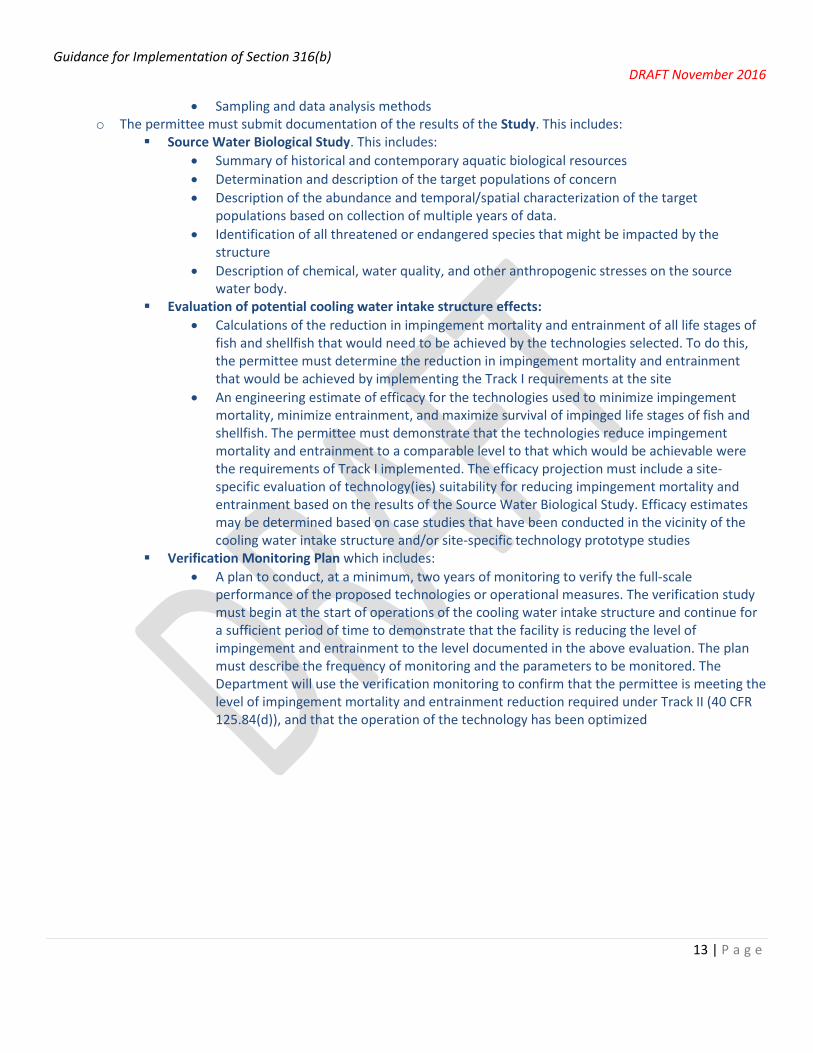
• Sampling and data analysis methods o The permittee must submit documentation of the results of the Study. This includes:
Source Water Biological Study. This includes: • Summary of historical and contemporary aquatic biological resources • Determination and description of the target populations of concern • Description of the abundance and temporal/spatial characterization of the target
populations based on collection of multiple years of data. • Identification of all threatened or endangered species that might be impacted by the
structure • Description of chemical, water quality, and other anthropogenic stresses on the source
water body. Evaluation of potential cooling water intake structure effects:
• Calculations of the reduction in impingement mortality and entrainment of all life stages of fish and shellfish that would need to be achieved by the technologies selected. To do this, the permittee must determine the reduction in impingement mortality and entrainment that would be achieved by implementing the Track I requirements at the site
• An engineering estimate of efficacy for the technologies used to minimize impingement mortality, minimize entrainment, and maximize survival of impinged life stages of fish and shellfish. The permittee must demonstrate that the technologies reduce impingement mortality and entrainment to a comparable level to that which would be achievable were the requirements of Track I implemented. The efficacy projection must include a site-specific evaluation of technology(ies) suitability for reducing impingement mortality and entrainment based on the results of the Source Water Biological Study. Efficacy estimates may be determined based on case studies that have been conducted in the vicinity of the cooling water intake structure and/or site-specific technology prototype studies
Verification Monitoring Plan which includes: • A plan to conduct, at a minimum, two years of monitoring to verify the full-scale
performance of the proposed technologies or operational measures. The verification study must begin at the start of operations of the cooling water intake structure and continue for a sufficient period of time to demonstrate that the facility is reducing the level of impingement and entrainment to the level documented in the above evaluation. The plan must describe the frequency of monitoring and the parameters to be monitored. The Department will use the verification monitoring to confirm that the permittee is meeting the level of impingement mortality and entrainment reduction required under Track II (40 CFR 125.84(d)), and that the operation of the technology has been optimized

Guidance for Implementation of Section 316(b) DRAFT November 2016
14 | P a g e
Figure 3. Application Materials Required For New Facilities (in addition to 40 CFR 122.21 (r) (2-4): Source Water Physical Data, Cooling Water Intake Structure Data, and Source Water Baseline Biological Characterization Data)
New Facilities40 CFR 125.86
Track I Track II
Intake Flow ≥ 10 MGD
10 MGD ≥ Intake Flow ≥ 2 MGD
Submit:• Flow Reduction Information• Velocity Information• Source Waterbody Flow Information • Design and Construction Technology
Plan• Demonstration that 125.84(b)(4) and
(b)(5) have been met
Submit:• Flow Reduction Information• Velocity Information• Source Waterbody Flow Information • Design and Construction Technology
Plan• Demonstration that 125.84(c)(3)
and (c)(4) have been met
Submit:• Source Waterbody Flow Information• Comprehensive Demonstration
Study

Guidance for Implementation of Section 316(b) DRAFT November 2016
15 | P a g e
4. Implementation of USEPA’s 2014 Existing Facilities Rule
On October 14, 2014, EPA’s final rule to establish requirements under section 316(b) for all existing facilities became effective. (79 FR 48300, August 15, 2014) (Hereafter referred to as the “EPA rule” or “2014 rule”.) This EPA rule established national requirements for the location, design, construction, and capacity of cooling water intake structures, to be applied to existing facilities that withdraw > 2 MGD and use at least 25% of that water exclusively for cooling purposes, by setting requirements that reflect BTA for minimizing adverse environmental impact. The rule requires that these BTA standards be implemented through NPDES permits.
4.1 Timeline for Submittal of Application Materials for Existing Facilities
Application Deadlines: EPA estimates that, for some facilities, it may take as long as 39 months to plan (6 months), collect (24 months), and compile (9 months) the data and studies required to be submitted with the permit application (79 FR 48359). With this in mind, the Department has divided permittees into three categories based upon their permit expiration dates. See Figures 4 and 5 at the end of this section.
Category I: Permits expired prior to October 14, 2014 that have not yet been issued Category II: Permits expiring after October 14, 2014 and prior to July 14, 2018 Category III: Permits expiring after July 14, 2018
Category I: Permits expired prior to October 14, 2014 that have not yet been issued
According to the EPA rule (40 CFR 125.95(b)(6)), an interim BTA must be determined using staff’s best professional judgment for Category I permittees for the coming permit term, unless the Department determines that the permittee has already completed sufficient studies to make a final determination using the standards set forth in the 2014 rule. Guidance related to making best professional judgment-based decisions is provided starting on page 64.
If sufficient studies have been completed, the Department may proceed with determining BTA in accordance with the new EPA rule. If not, Category I permittees will be required to submit all application materials by their next permit application date and a final BTA determination based on the 2014 rule will be made at the next reissuance.
Category II: Permits expiring after October 14, 2014 and prior to July 14, 2018
According to the EPA rule )40 CFR 125.95(a)(2)), permittees who fall within Category II may request an alternate schedule for completion of the required studies. In order to file this request, permittees must send a letter to the Department, addressed to the permit drafter. If an alternate schedule request letter is not sent or the requested alternate schedule is not approved by the Department, the permittee will have to submit all required materials with the first permit application due after October 14, 2014. Alternate schedule requests should include the following information:
1. A list of studies that have already been completed (see application requirements starting on page 19).

Guidance for Implementation of Section 316(b) DRAFT November 2016
16 | P a g e
2. A proposed schedule for completion of any incomplete studies and/or preparation of application materials. The schedule should not extend past July 14, 2018, in most cases. If the permittee would like to request a longer timeline, the letter will need to include reasons for doing so.
3. A justification for the extension request.
4. A signature from the permittee’s authorized representative.
The DNR requested that alternate schedule requests should have been received by the permit drafter by October 14, 2015 or six months before the expiration of the current permit, whichever occurred first, in order to allow time for completion of studies in the event that the alternate schedule is not granted. If a Category II permittee has already filed his/her application with the Department and did not submit all the required application materials nor an alternate schedule request, he/she should contact the Department’s permit drafter immediately. If, due to extenuating circumstances, it is not possible for a Category II permittee to request an alternate schedule by the above dates, the permittee should contact the permit drafter.
The Department will need to make interim BTA determinations for any permittees that receive alternate schedules, using best professional judgment. Guidance related to making best professional judgment-based decisions is provided starting on page 64. After all application materials have been submitted, a final BTA determination based on the 2014 rule will be made at the next permit reissuance.
Category III: Permits expiring after July 14, 2018
According to the EPA rule (40 CFR 125.95(a)(1)), permittees that fall into Category III are required to submit all studies no later than their next permit application deadline, typically six months before their permit expiration date. However, it is recommended that permittees submit study information as soon as it is available, so that the permittee and Department staff can ensure that application submittals will be adequate and complete.

Guidance for Implementation of Section 316(b) DRAFT November 2016
Category I - (Permit applied for before 10/14/14)
Category II – (Permits applied for on/after 10/14/14, or permits expiring on/before 7/14/18)
Category III – (Permits expiring after 7/14/18)
Planning Data Collection Compilation
Planning Compilation Data Collection
Year 5
Figure 4. Timelines for Facilities > 2 MGD & < 125 MGD
Year -.5
Year 0 (Permit Expiration)
10/14/14
Year 4.5 Year 0
Permit is reissued with BPJ BTA Determination (see page 64)
Submit 122.21 (r) materials with permit application
Permittee Applies for Alternate Schedule (by 10/14/15 or date agreed upon with
permit drafter)
If approved, create a schedule at least as stringent as Category I Schedule
If rejected or unreceived, use Category III Schedule
Federal 316(b) Rule Effective Date
Permit is reissued with BTA Determinations (based on 40 CFR 125.90-98)
Submit 122.21 (r) materials with permit application
Permit reissued with BTA Determinations
(based on 40 CFR 125.90-98)
Year -1.25 Year -2.25 Year -2.75
Year 3.75 Year 2.25 Year 2.75
Suggested: Share Study Plan with DNR
Suggested: Share Study Plan with DNR
Alternate Schedule Requests must include: 1. List of 122.21 (r) studies already complete
2. Proposed Schedule for completion of remaining studies (preferably not extending
past 7/14/2018) 3. Justification of need for extension

Guidance for Implementation of Section 316(b) DRAFT November 2016
Category I - (Permit applied for before 10/14/14)
Category II – (Permits applied for on/after 10/14/14, or permits expiring on/before 7/14/18)
Category III – (Permits expiring after 7/14/18)
Compilation Data Collection Planning
Planning Compilation Data Collection
Year 5
Figure 5. Timelines for Facilities > 125 MGD
Year -.5
Year 0 (Permit Expiration)
10/14/14
Year 4.5 Year 0
Permit is reissued with BPJ BTA Determination (see page 64)
Submit 122.21 (r) materials with permit application
Federal 316(b) Rule Effective Date
Permit is reissued with BTA Determinations (based on 40 CFR 125.90-98)
Submit 122.21 (r) materials with permit application
Permit reissued with BTA Determinations
(based on 40 CFR 125.90-98)
Year -1.25 Year -3.25 Year -3.75
Year 3.75 Year 1.25 Year 1.75
Suggested: Share Study Plan with DNR
Suggested: Share Study Plan with DNR
Permittee Applies for Alternate Schedule (by 10/14/15 or date agreed upon with
permit drafter)
If approved, create a schedule at least as stringent as Category I Schedule
If rejected or unreceived, use Category III Schedule
Alternate Schedule Requests must include: 1. List of 122.21 (r) studies already complete
2. Proposed Schedule for completion of remaining studies (preferably not extending
past 7/14/2018) 3. Justification of need for extension

Guidance for Implementation of Section 316(b) DRAFT November 2016
19 | P a g e
4.2 Application Materials Required For Existing Facilities
A description of each of the permit application requirements from the 2014 EPA rule is given below. All permit application requirements are due no later than 180 days before the current permit expires.
After the first permit reissuance that includes BTA determinations made in accordance with 40 CFR 125.94 (c) and (d), the permittee may request that the Department waive the requirement to submit any of the materials below (see 40 CFR 125.95(c)), if information submitted in a previous reissuance application is still relevant. The Department may approve the request if source water, intake structure, cooling water system, and operating conditions at the facility remain substantially unchanged since the previous application. Any part of the request could be accepted or rejected, based on this assessment. The request for reduced permit application requirements would have to be submitted to the Department before required data collection periods would need to begin (e.g., 2 ½ years before permit expiration), so this data can still be collected if the request is denied.
Historical studies may be considered relevant if the study’s dominant species, biomass, and abundance estimates are similar to those of current studies at the same or nearby sites.
See Figure 6 for a flowchart depicting which application materials required to be submitted for a facility of any given flow rate. As a clarification, even facilities that withdraw less than 2 MGD (Design Intake Flow) must submit the materials listed in 40 CFR 122.21 (r) (2-8). Please note, however, that (r) (4) and (7) only require submittal of previously conducted studies. Completion of new studies is optional for these materials, but efforts should be made to attain any previously conducted studies from nearby industrial facilities subject to 316(b), dams (FERC entrainment studies), and the Department. Also note that facilities withdrawing less than 2 MGD (DIF) do not need to submit (r) (6) because they do not need to comply with the impingement mortality standard.
• § 122.21(r)(2) Source Water Physical Data
(Note: this requirement is the same as was in the 2004 Phase II rule.)
The permittee is required to submit data to evaluate the waterbody affected by the cooling water intake structure. The information required includes a narrative description of all source water bodies used by the facility, identification of hydrological and geomorphological features, and location maps. This information may be used by staff to evaluate the appropriateness of proposed design or technologies. The three required pieces are described below in greater detail.
� Narrative Description of Source Water Bodies: The permittee shall include scaled drawings showing the physical configuration of each surface water body used by the facility, areal dimensions, depths, and temperature regimes. A narrative description of each water body shall summarize the information above to support the waterbody classification and the location and design of the intake structure. This section may also include any other relevant information that supports the design and location of the intake structure.
� Hydrological and Geomorphological Features: This section shall include the identification of all hydrological and geomorphological features within each source water body. The permittee may also include a description of the area of influence of each intake structure. The methods and results of any physical study to determine the area of influence should be included in this section.
� Locational Maps: Include a map showing the location of each intake structure and each source waterbody location.

Guidance for Implementation of Section 316(b) DRAFT November 2016
20 | P a g e
Thermal regimes will be used to assess any potential changes to the thermal plume that might result from potential upgrades. Area of influence delineations should be submitted if barrier nets or aquatic filter barriers may be proposed to exclude organisms from the area of influence. • § 122.21(r)(3) Cooling Water Intake Structure Data
(Note: this requirement is the same as was in the 2004 Phase II rule.)
The permittee is required to submit a narrative description of the configuration of each cooling water intake structure. This description shall include the following information:
� Location in the waterbody and water column � Latitude and longitude coordinates of each intake in degrees, minutes, and seconds � Description of the operation of each intake
o Design intake flow o Daily hours of operation o Number of operating days per year o Seasonal operational changes
� Water balance diagram that includes, with associated average and maximum flow rates: o All sources of water to the facility o All recirculating flows o All discharges
� Engineering drawings of the cooling water intake structure.
This data may be used to characterize the intake structure and evaluate the potential for impingement and entrainment of aquatic organisms. Information on the design of the intake and its location in the water column allows for speculation of which species and life stages might be subject to impingement and entrainment, but all species must be evaluated. A diagram of the facility’s water balance can be used to identify the proportion of intake water used for cooling, make-up, and process water, as well as any cooling water supplied by alternate sources, such as reuse of another facility’s effluent. The water balance diagram also provides a picture of the total flow in and out of the facility, and can be used to evaluate potential for reuse of gray water or wastewater.
• § 122.21(r)(4) Source Water Baseline Biological Characterization Data
(Note: this requirement is similar to that required by Phase I and Phase II rules but the 2014 Rule added requirements)
Existing facilities are required to characterize the biological community (fish and shellfish) in the hydraulic zone of influence of each cooling water intake structure and to characterize the operation of each intake. Supporting information must include existing data (e.g., from literature or nearby facilities, dams, or Department or USGS monitoring efforts), if available. Permittees may contact the Department’s fisheries management biologists to inquire about existing fisheries data. Contact information for fisheries management biologists is available here: http://dnr.wi.gov/topic/Fishing/people/fisheriesbiologists.html. Additionally, the permittee may supplement any existing data with newly conducted field studies if they choose to do so. The study area should include the hydraulic zone of influence of the cooling water intake structure, at a minimum. If the permittee wishes to use existing data from

Guidance for Implementation of Section 316(b) DRAFT November 2016
21 | P a g e
a nearby facility, dam, or the Department, they must evaluate the applicability of the data to their area of influence. The submittal must include:
� Identification of data that are not available and efforts made to identify all sources of data � A list of fish and shellfish species (or relevant taxa) for all life stages found in or near the hydraulic zone of
influence. All species should be evaluated, including the forage base and those species most important in terms of significance to commercial and recreational fisheries. For each species, the permittee should identify:
o The relative abundance of each species in the area of influence of the intake structure o Period of peak abundance o The primary period of reproduction o Larval Recruitment
(Note: information on reproduction periods of fish is available in the technical support document for Wisconsin’s thermal rule, available upon request)
� Identification of the species and life stages that would be most susceptible to impingement and entrainment � A description of any protective measures and stabilization activities that have been implemented � A description on how the protective measures and activities affected the baseline water condition � Data representative of the seasonal and daily activities (e.g., feeding and water column migration) of biological
organisms in the vicinity of the intake structure � Identification of all federally- and state-listed threatened and endangered species and/or designated critical
habitat that are or may be present in the area of influence according to § 125.95(f). State listed species can be found on the Department’s Natural Heritage Inventory (NHI) portal (http://dnr.wi.gov/topic/nhi/). Federally-listed species can be found on the USFWS website (https://www.fws.gov/midwest/endangered/lists/wisc-spp.html) or through the GIS-based Information for Planning and Conservation tool (https://ecos.fws.gov/ipac/). At the time of publication, there are no federally-listed fish present in Wisconsin, although federally-listed mussels are present in several rivers.
� Documentation of any public participation or coordination with Federal or State agencies undertaken
If the permittee wishes to supplement the information with field collected data, supporting documentation for the Source Water Baseline Biological Characterization Data should include:
� A description of all methods and quality assurance procedures for sampling (the Department recommends a study plan is shared before sampling begins)
� Data analysis including a description of the study area � Taxonomic identification to the lowest taxon possible of sampled and evaluated biological assemblages
(including all life stages of fish and shellfish) � Sampling and data analysis methods. The sampling and data analysis methods used must be appropriate for a
quantitative survey and based on consideration of methods used in other biological studies performed in the same source waterbody.
If the permittee wishes to make a demonstration that a fish present in the vicinity of the intake should be deemed a “fragile species” and thereby not counted in impingement mortality counts, the permittee should make this demonstration under this submittal. Such a submittal will need to entail independent or peer reviewed scientific study that indicates that the species will have an impingement survival rate of less than 30% on an optimized modified traveling screen. Such a demonstration will be reviewed by the Department’s fisheries management biologists. Alewives, rainbow smelt, and gizzard shad are considered fragile species on a statewide basis by default; no study is

Guidance for Implementation of Section 316(b) DRAFT November 2016
22 | P a g e
required to discount these species from impingement mortality rate calculations. For more information on fragile species, see pg. 48.
• § 122.21(r)(5) Cooling Water System Data
(Note: this requirement is similar to that required by the Phase II rule, but the 2014 Rule added requirements)
The permittee must provide a narrative description of the operation of the cooling water system and its relationship to cooling water intake structures (including the use of helper towers). The following information is required for each cooling water intake structure in use:
� The proportion of the design intake flow that is used in the system, including a distribution of water used for contact cooling, non-contact cooling, and process uses
� A distribution of water reuse (to include cooling water reused as process water, process water reused for cooling, and the use of gray water for cooling);
� A description of reductions in total withdrawals including intake flow reductions already achieved through minimized process water withdrawals
� A description of any cooling water that is used in a manufacturing process either before or after it is used for cooling, including other recycled process water flows;
� The proportion of the source waterbody withdrawn on a monthly basis � The number of days of the year the cooling water system is in operation � Seasonal changes in the operation of the system, if applicable � Engineering design and calculations prepared by a qualified professional and supporting data to support the
descriptions provided above � A description of existing impingement and entrainment technologies or operational measures � A summary of the performance of the technologies or operational measures including:
o reductions due to intake location o reductions in total water withdrawals and usage o efficiencies in energy production that result in the use of less cooling water (e.g., combined cycle and
cogeneration)
The information in this submittal may be used to: -evaluate applicability of federal regulations (quantify percent used for cooling)
-demonstrate the extent to which flow reductions have already been achieved at the facility level. This is especially relevant for permittees choosing to comply with the Impingement Mortality BTA standard by using a system of technologies, management practices, and operational measures that consists of use of flow reduction measures or water reuse for cooling. It also holds relevance for facilities indicating no additional controls are necessary for entrainment BTA due to recent flow reductions.
-further characterize or estimate entrainment impacts or reductions. -evaluate water reuse as a potential entrainment BTA.
-inform the potential for seasonal deployment of technologies (e.g., barrier nets) to reduce impingement rates during peak months of the year.
-support an 8% capacity utilization rate demonstration.

Guidance for Implementation of Section 316(b) DRAFT November 2016
23 | P a g e
• § 122.21(r)(6) Chosen Method of Compliance with Impingement Mortality Standard
The permittee must identify its chosen approach to meet the impingement mortality standard. The permittee can identify one compliance method for the entire facility or, alternatively, separate methods for each intake structure at the facility. The compliance options located in §125.94 (c) are given below:
BTA Standards for Impingement Mortality Option Description Type
1 Closed-cycle Recirculating System Standard 2 0.5 fps through-screed design velocity Standard 3 0.5 fps through-screen actual velocity Standard 4 Existing Offshore Velocity Cap Standard 5 Modified Traveling Screens Standard 6 System of Technologies Standard 7 24% Impingement Mortality Standard Standard 8 Additional Measures for Shellfish Additional 9 Additional Measures for other Species Additional
10 Reuse of other water for cooling Alternate 11 De Minimis Alternate 12 <8% Capacity Utilization Rate Alternate
Options 1, 2 and 4 are pre-approved technologies that require no demonstration or only a minimal demonstration that the flow reduction and/or control measures are functioning as envisioned. Options 3, 5, 6, and 7 require more detailed information to be submitted before the Department can specify that option as the requirement to control impingement mortality. Facilities must comply with options 8 and 9 if the Department requires such additional measures. Options 10, 11, and 12 are alternate compliance options which require additional submittals. Additional information regarding each compliance option can be found beginning on page 37.
Facilities choosing Option 5 to achieve the impingement mortality standard through the operation of a modified traveling screen must submit an impingement technology performance optimization study according to § 122.21(r) (6) (i). Common optimization factors include screen rotation speed, screen rotation frequency, spray wash pressure, spray nozzle orientation/spacing, transport water velocity, and transport water flow rate. The site-specific study must demonstrate that the modified traveling screen has been optimized to minimize impingement mortality. The study must include:
� A complete description of the modified traveling screens and associated equipment, including o Type of mesh (e.g. woven or drilled, material, etc.) o Mesh slot size o Pressure sprays o Mechanism for fish return
� A minimum of two years of biological data collection measuring the reduction in impingement mortality achieved by the modified traveling screen
� Sampling at least monthly during that two year period

Guidance for Implementation of Section 316(b) DRAFT November 2016
24 | P a g e
� Biological data collection representative of the impingement and impingement mortality at the intakes subject to this provision:
� Documentation of the methods used, including counting of moribund organisms, latent mortality, holding times, counting of entrapment, and taxonomic identification
� Demonstration that previously collected data is still relevant and representative of facility and source water conditions if it is greater than 10 years old
� The percent impingement mortality reflecting optimized operation of the modified traveling screen and supporting calculations
� A summary of the study results and recommended optimized operating procedures
The Department can establish more frequent collection, specific sampling methods, or additional protocols to be used, when warranted. If the permittee intends to return fish and shellfish to a different waterbody than the source waterbody that is used to withdraw cooling water, this should be identified as part of the impingement technology performance optimization study (§ 122.21(r) (6) (i)). Department staff should consult with a Fisheries Biologist to determine whether such a return location is appropriate.
Special care should be taken to maximize the reliability of the study results. Firstly, it is critically important to minimize the effect of “nuisance variables” on the study results. These include weather variations, variation in species, and other random effects. The use of hatchery fish of a single species and size could potentially eliminate variation in survival due to variation in species impinged, if approved by the DNR Fisheries Management. While the rule allows longer holding periods, studies have shown that there is little difference in latent mortality of adult and juvenile fish after 24 hours in holding. Sample sizes of 200 fish impinged per sample date are suggested.1 The permittee should discuss nuisance variables and controls with the permit drafter before commencing the study in order to agree upon a reasonable degree of rigor and sampling frequency. In some cases, especially where the screen is optimally designed and impingement impacts are expected to be low, information obtained from a literature review of optimization studies at other similar facilities may be reason for less frequent samples of intense rigor. For example, sampling must be conducted at least monthly in all cases, but fish from hatcheries may need not be used each month in cases where optimal conditions can be predicted with a greater level of certainty.
Facilities choosing Option 6 to achieve the impingement mortality standard through the operation of a system of technologies, must submit an impingement technology performance optimization study under § 122.21(r) (6) (ii). The “system” may consist of one or more technologies already in place, or may be combined with newly installed technologies. The system of technologies may also include operational measures or best management practices such as flow reductions, seasonal operation, unit closure, credit for intake location, and behavioral deterrent systems. The site-specific impingement technology performance optimization study must include:
1 Garrett, William E. Jr. and Justin B. Mitchell, “Biological Optimization of Traveling Water Screens at Plant Barry, AL,” Alabama Power Company Presentation, EPRI 316(b) Conference, Charlotte, November 10, 2015.

Guidance for Implementation of Section 316(b) DRAFT November 2016
25 | P a g e
� Documentation that the operation of the system of technologies has been optimized to minimize impingement mortality. This should include identification of parameters that can be varied and optimized and an identification of optimal settings.
� Identification of an impingement mortality rate that represents a “optimized” operation of the system � A minimum of 2 years of biological data measuring the reduction in impingement mortality achieved by the
system � A description of any sampling or data collection approach used in measuring the rate of impingement,
impingement mortality, or flow reductions. � Documentation on how each system element contributes to the overall system performance
It is possible for a facility to reduce its rate of impingement, but have the same number of impinged fish die, thereby increasing the percent impingement mortality calculated by the facility. EPA stated in the preamble to its rule that it does not intend for such facilities to be penalized for significant reductions in impingement rates obtained through existing technologies and practices in place. Therefore, where the traditional impingement mortality calculation is not applicable, the optimization study for systems of technologies may evaluate impingement mortality rate as (79 FR 48365):
Number experiencing impingement mortality in a given month Number expected to be impinged at a facility of the same AIF with once through cooling
and an unmodified travelling screen on the shoreline of the source waterbody
The denominator may be estimated based on rates of impingement prior to implementation of the system of technologies, operational measures, or management practices. Changes in flow rates, impingement rates, and population levels or density of fish and shellfish in the source water may also be taken into account.
Fragile species (alewives, gizzard shad, and rainbow smelt) do not need to be counted when calculating impingement mortality.
Flow reduction may be used to meet or partially meet impingement mortality BTA. If this is the case, two years of intake flow data must be submitted with the optimization study. This, plus the data collected under the Source Water Baseline Biological Characterization study, can be used to document how flow reduction results in a reduced rate of impingement and whether such reductions are seasonal or intermittent (79 FR 48365). In other words, a 40% reduction in flow does not directly translate to a 40% reduction in impingement mortality; rather, burst swimming speeds of present species, density of fish and shellfish, and temporal variability in biodensity and flow rates all should be considered.
Finally, the optimization study requires the calculation of impingement mortality for each component of the system of technologies. In addition, the study must identify and justify the percent impingement mortality that reflects a state of “optimized” operation of the total system of technologies, operational measures, and best management practices.
If the site-specific impingement study demonstrates that the modified traveling screen (as defined in § 125.92) or system of technologies have been optimized to minimize impingement mortality, the Department may determine that the technology is BTA for impingement mortality at the site. The Department is then required to include permit conditions to ensure the technology will perform as demonstrated. For a modified traveling screen, this may include requirements for spray pressure, rotation speed, frequency of rotation, flow in the fish return trough, etc.

Guidance for Implementation of Section 316(b) DRAFT November 2016
26 | P a g e
Note that EPA states in the preamble to the 2014 rule that its intent is for these studies to function to optimize performance, which is not the same as requiring a study merely demonstrating a specific numeric level of performance for impingement mortality has been or can be achieved (79 FR 48365). EPA expects that the majority of modified traveling screens will perform at a level better than the 24% impingement mortality standard. In fact, EPA has documented several modified traveling screens that perform at a rate of impingement mortality lower than 10 percent (79 FR 48365).
• § 122.21(r)(7) Entrainment Performance Studies
The permittee must submit a description of any previously conducted biological survival studies at the facility and a summary of any conclusions or results. Submittals should include any site-specific studies addressing efficacy of entrainment reduction technologies, through-facility entrainment survival (distinguished for eggs and larvae), and entrainment analyses. Studies from other locations may be submitted provided a justification as to why the data are relevant and representative of conditions at the facility. Because of changes in the waterbody over time, studies older than 10 years must include an explanation of why the data are still relevant and representative of conditions at the facility. If the studies are no longer relevant, the Department may reject the data (79 FR 48366).
EPA’s rule does not require permittees to conduct new studies to fulfill this requirement. This requirement is intended to obtain results for relevant studies that have already been conducted to comply with past iterations of the rule.
The Department should use all available information when establishing technology-based requirements for entrainment.
• § 122.21(r)(8) Operational Status
The permittee must submit a description of the operational status of each unit for which a cooling water intake structure provides water for cooling. These descriptions must contain information on:
� Age and status of each unit � Capacity utilization for the previous five years (including any unusual or extended outages that significantly
affect the facility’s reporting of flow, impingement, or other data) � Any major upgrades completed in the past 15 years(e.g., boiler or condenser replacement, changes to fuel type,
a new production line) � Completed, approved or scheduled uprates and Nuclear Regulatory Commission relicensing status for nuclear
facilities � Plans or schedules for decommissioning or replacement of units � Current and future production schedules for manufacturing facilities
The above information will be used primarily to determine the necessity for upgrades to comply with the BTA for entrainment and also for timing of compliance schedules. If a facility makes a case that an upcoming planned closure means that any upgrades to minimize entrainment are unwarranted, a signed certification from the authorized representative should accompany this submittal. The certification should state that the plant will close by a set date. This information could also support a claim that capacity utilization is < 8% averaged over a 24-month period, supporting a determination that less stringent impingement controls are warranted. In such a case, the through screen intake velocity during shutdown periods should be provided if water will be withdrawn during shutdown. Energy reliability is also a factor that the Department may consider when establishing entrainment controls (see § 125.98 (f) (3)).

Guidance for Implementation of Section 316(b) DRAFT November 2016
27 | P a g e
• § 122.21(r)(9) Entrainment Characterization Study
As noted above, EPA’s rule only requires the information in § 122.21 (r) (9) to (13) from facilities with an AIF > 125 MGD. The Department can reduce or waive some or all of this information for closed-cycle recirculating systems and/or for those with an AIF < 125 MGD. However, the Department intends to require that facilities with an AIF < 125 MGD do submit one year of entrainment data, in most cases. See the next page for details.
Facilities with AIF > 125 MGD must develop a study that includes a minimum of two years of entrainment data collection. EPA’s rule suggests that the permittee extend the data collection methods and frequency used to develop the source water characterization required by earlier 316(b) rules at § 122.21(r) (4), to develop the Entrainment Characterization Study. The study must include:
� Complete documentation of the data collection period and frequency of entrainment characterization � Identification of the organisms sampled to the lowest taxon possible1 � Data collection representative of entrainment at each intake and the study � Documentation on how the location of the intake in the waterbody and the water column are accounted for. � Intake flows associated with the data collection. � Data analysis/extrapolation to determine total entrainment and entrainment mortality2 � Documentation of the methods used for identifying latent mortality � Documentation of all methods and qa/qc procedures used for sampling and data analysis
1Discussions with permittees and consultants suggest that cost for identification of organisms is on the order of $300-400/1L sample bottle. This price may fluctuate with demand and availability of labs. 2Extrapolation should not be a simple calculation of (number of individuals entrained/days of sampling)*365 days. Rather, it should take into account known spikes in abundance during certain times of the year. This could be accomplished by performing a polynomial regression (order TBD based on best fit) on the data points (x = date, y=number entrained per day) and integrating the regression. Any other methods used, assumptions made, or factors taken into account should be clearly explained. For example, if data from a nearby facility is used to bolster an entrainment characterization, it should be weighted by flow at facility A/flow at facility B.
Sampling must occur over a period of at least two years in order to sufficiently characterize annual and seasonal variations in entrainment, “including variations related to climate, weather, spawning, feeding, and water column migration” (79 FR 48366). Each sampling occurrence should be performed either continuously for 24 hours or as a composite sample spread over the course of 24 hours in order to capture diel variations as well.
Facilities may use historical data that are representative of current conditions at the site, provided additional documentation regarding the continued relevance of the data is included.
This submittal will help Department staff determine the site-specific entrainment BTA standard, as number and types of organisms entrained is a factor that must be considered under 40 CFR 125.98 (f) (2). It will establish a baseline entrainment rate for facilities with no entrainment minimization technologies, and it will help evaluate the efficacy of technologies already in place and other site-specific factors such as intake location (79 FR 48366).
Note for Facilities <125 MGD: While the EPA rule does not require facilities with AIF < 125 MGD to complete an entrainment characterization study, the Department is required to make a BTA determination with each permit reissuance. When completing a BTA determination, staff must consider the numbers and types of organisms entrained (see § 125.98 (f) (2)). In order to have sufficient information to consider the numbers and types of species entrained, it is recommended that these facilities

Guidance for Implementation of Section 316(b) DRAFT November 2016
28 | P a g e
complete, at a minimum, 6 months of monthly sampling during the primary period of reproduction, with biweekly sampling during the month or two months of peak abundance, as anticipated by the Department’s regional fisheries management biologists. Historical data or data from nearby facilities may be used in place of new data collection, if determined to be relevant at the facility under current conditions.
Guidelines for Entrainment Characterization Sampling: Time and Frequency: For facilities >125MGD AIF: Sampling period should cover two periods when eggs/larvae are expected to be present in the water column for facilities >125MGD AIF. Sampling should occur once every two weeks while eggs/larvae are present in the water column. The regional fisheries management biologist should determine the duration of this period (when fish eggs and larvae are expected to be present in the water column). The default period is April-October. The permittee may elect to sample more frequently during expected times of high entrainment in order to accurately represent their entrainment. For facilities <125MGD AIF: Sampling period should cover one period when eggs/larvae are expected to be present in the water column for facilities <125MGD AIF. Sampling should occur once per month throughout the period with biweekly sampling during the one or two months of peak abundance, as anticipated by the Department’s regional fisheries management biologists. Each intake sampling event should span a 24-hour period. Sampling may occur continuously during the 24-hour period, or the permittee may elect to perform a composite sample over the 24-hour period. If the latter approach is selected, this 24-hour period should be broken into sub-periods of equal frequency and duration (calculated to sample at least 100m3 of water) in order to capture diel variations in entrainment. Nets should be emptied promptly in order to prevent damage to organisms retained in the net. In situations where continuous, as opposed to composite, sampling is conducted, nets should be emptied into a sample bottle with preservative every few hours, at a minimum. If in-river sampling is conducted in order to establish an ecological context (recommended), river tows should sample, at a minimum, 100 m3 per sample, and each of these tows should be conducted during both day and night. Sampling Location: Sampling should occur at or near the intake structure and before the condenser and/or clarifier, rather than at the discharge, as damage of organisms within the plant can make species identification more difficult for samples collected at the discharge, and a loss of organisms may occur within the plant due to this damage. Additionally, the sampling net should be positioned in an area that is vertically well-mixed, or multiple nets should be used in order to capture entrainment at different depths in order to account for stratified biodensity. Sampling should not occur after a screen that is finer than 3/8” mesh, as this will exclude some entrainable organisms. If in-river sampling is conducted in order to establish an ecological context (recommended), it is suggested that tows are conducted at a minimum of three locations, all immediately upstream of the intake structure: one in the middle of the river transect, and one near each shoreline or the midpoints between the center of the river and the shorelines. Again, each of these tows should be conducted during both day and night. Equipment: A net with a mesh size less than or equal to 500 µm should be used (~300 µm preferred). A preservative should also be added to samples immediately following collection in order to minimize decomposition before identification. Species identification: Species should be identified to the lowest taxon possible. Even highly trained biologists may only be able to identify up to two-thirds of sampled individuals. If T&E species are identified, the Department should be notified immediately. If sample sizes are unmanageably large, they may be split into reasonably-sized subsamples for identification. A key for species identification of eggs, yolk sac larvae, and larvae has been developed by EPRI and is

Guidance for Implementation of Section 316(b) DRAFT November 2016
29 | P a g e
available to the public at the following link: http://www.larvalfishid.com/ . EPRI has indicated that it will maintain this page for at least 5 years (until at least 2021). Permitting: If T&E species are possibly present in the sampling area, permission for incidental take must be obtained from the USFWS and DNR. This can occur through one of three ways: 1) The sampling consultant has a Section 10(a)(1)(A) permit for research. 2) The facility has a Section 10(a)(1)(B) permit (called a Habitat Conservation Plan (HCP)). 3) The sampling consultant or facility gets an ITS (Incidental Take Statement). This process can take a significant amount of time, and missed permit deadlines due to not having the appropriate permit are unacceptable, as the facility should have applied for incidental take coverage in the 1970s if they withdraw water. Sampling methodology may factor into USFWS’s decision to issue permission for incidental take. The DNR’s policy on Incidental Take can be found here: http://dnr.wi.gov/topic/erreview/take.html .
• § 122.21(r)(10) Comprehensive Technical Feasibility and Cost Evaluation Study
Facilities with an AIF > 125 MGD must submit an engineering study of the technical feasibility and incremental costs of entrainment control options. The study must include:
� Evaluation of Technical feasibility for o Closed-cycle cooling, o Fine-mesh screens (< 2 mm), o Reuse of water or alternate sources of cooling water (from within the facility and nearby facilities) o Variable speed pumps o Wells or Ranney Collectors o Any other entrainment reduction technologies identified by the permittee or requested by the Department.
� This study must include a description of all technologies and operational measures considered (including alternative closed-cycle recirculating system designs such as natural draft cooling towers, hybrids, compact or multi-cell arrangements, or the conversion of helper towers to a fully recirculating system)
� A discussion of land availability, including land and adjacent acres available due to o Generating unit retirements o Production unit retirements o Other buildings and equipment retirements o Potential repurposing of areas devoted to ponds, coal piles, rail yards, transmission yards, and parking lots
� Discussion of available sources of process water, grey water, waste water, reclaimed water, or other waters of appropriate quantity and quality for use as some or all of the cooling water needs1
� Documentation of factors other than cost that make a technology impractical or infeasible for further evaluation 1Should examine reuse of effluent from both the facility and nearby facilities. Reuse of water that constitutes only partial reductions in intake water should be examined as well.
This study must include engineering cost estimates of all technologies evaluated above. Facility costs must be adjusted to estimate social costs and the permittee must discuss facility level compliance and social costs independently. The EPA rule requires that cost information be presented as both the permittee’s compliance costs and the social costs, and in net present value terms and the corresponding annual value.

Guidance for Implementation of Section 316(b) DRAFT November 2016
30 | P a g e
The rule defines social costs as “the costs estimated from the viewpoint of society, rather than individual stakeholders. Social cost represents the total burden imposed on the economy; it is the sum of all costs incurred associate with taking actions. These opportunity costs consist of the value lost to society of all the goods and services that will not be produced and consumed as a facility complies with permit requirements, and society reallocates resources away from other production activities and towards minimizing adverse environmental impacts” (40 CFR 125.92 (y)).
Social costs can include increases in electricity rates for homeowners (including those due to energy penalty), lost jobs/lost money into the economy, lost tax revenue from a power plant or manufacturing facility, etc. Please note that downtime resulting from required upgrades does not necessarily translate to a social cost, although it is a cost to the facility.
Social costs should be calculated as a net present value using the social discount rate rather than market interest rates. If the social discount rate is unknown or cannot be estimated, discount rates of both 3 and 7 percent should be used to calculate a range of net present values. Social costs should be calculated pre-tax and should include the Department’s administrative costs (estimate $30/hour of work and 25-50 hours for an interim BTA determination and 50-100 hours for the first “final” BTA determination, depending on complexity and level of involvement of fisheries and regional compliance staff).
EPA is in the process of developing a calculator for social costs. The Department will notify permittees when this becomes available.
The permittee should also provide facility level compliance costs. However, such costs must be provided separately from social costs. The facility level compliance cost evaluation must include:
� Engineering cost estimates of all technologies considered � Discussion or documentation of any outages, downtime, energy penalties, or other effects on revenue � Evaluation based on least-cost approaches to implementing each candidate technology while meeting all
regulatory and operational requirements of the facility � The facility’s administrative costs, including cost of permit application � Costs and explanation of any additional facility modifications necessary to support construction and operation of
the technologies considered above. o Capital costs o Operation costs
The cost evaluation should also address any non-water quality and other impacts identified in r(12) below. All assumptions regarding depreciation schedules, interest rates, discount rates, useful life of technology, and any other assumptions must be identified and explained.
Additional guidance on compliance cost and social cost can be found in Chapter 8 of EPA’s 2010 “Guidelines for Preparing Economic Analyses” (DCN 10-3258) at the following address: http://yosemite.epa.gov/ee/epa/eerm.nsf/vwAN/EE-0568-50.pdf/$file/EE-0568-50.pdf. The permittee must obtain peer review of their Comprehensive Technical Feasibility and Cost Evaluation Study per §122.21 (r) (13).
Guidance for Implementation of Section 316(b) DRAFT November 2016
31 | P a g e
• § 122.21(r)(11) Benefits Valuation Study
Facilities with an AIF > 125 MGD must submit an analysis of the benefits of the entrainment reduction technologies evaluated in § 122.21(r)(10). The study should include the following pieces:
� Incremental changes in the impingement mortality and entrainment of individual fish and shellfish for all exposed life stages,
� Description of any estimates of changes in stock and harvest levels of commercial, recreational, or forage species
� Description of any monetized values assigned to changes in the stock or harvest of commercial, recreational, or forage fish and shellfish species, and any other ecosystem or nonuse benefits
o A nonuse benefit is a value that an individual places on knowing that an entity or condition exists, even though the individual may not directly use it either now or in the future.
� Discussion of previous mitigation efforts completed prior to October 14, 2014 o How long have these practices been in place? o Ecosystem viability and fish abundance in the area of influence
� Discussion, quantification, and monetization of any other benefits expected to accrue to the environment and local communities. This may include improvements for mammals, birds, and other organisms and aquatic habitats.
� Discussion, quantification, and monetization of any benefits expected to result from any reductions in thermal discharges from entrainment technologies
o identify increased or decreased thermal discharges o evaluate the potential changes in facility capacity, operations, and reliability due to relaxed permitting
constraints related to thermal discharges o Willingness-to-pay (WTP) can be used to monetize benefits (WTP captures monetary benefits by
measuring what individuals are willing to forgo in order to enjoy a particular benefit) � Benefits that cannot be monetized should be quantified where feasible and discussed qualitatively where not. � Peer review of the benefits evaluation study per 122.21(r) (13)
EPA is in the process of developing a calculator for quantifying benefits. The Department will notify permittees when this becomes available.
Benefits should be monetized where possible, and quantified in in physical or biological units where monetization is not possible. As a last resort, benefits should be expressed qualitatively.
Data from the Entrainment Characterization Study in § 122.21(r)(9) may be used to inform the benefits valuation. Any methods used to monetize improvements to fisheries or to convert impingement and entrainment rates to age one equivalents should be explained in detail. All assumptions and inputs should be identified and justified.
Non-use benefits should be included in the analysis. The Department recognizes that non-use benefits are difficult to quantify because they cannot be informed by observed changes in behavior. However, EPA’s willingness-to-pay survey may be used as a basis for approximations (See chapter 11 of https://www.epa.gov/sites/production/files/2015-

Guidance for Implementation of Section 316(b) DRAFT November 2016
32 | P a g e
05/documents/cooling-water_phase-4_benefits_2014.pdf ). This revealed that inland households, on average, would pay an additional $0.50/year in 2011 dollars for a one percent improvement in the number of fish saved.2
The Department is required to consider cost-benefit information when making an entrainment BTA determination. However, if the benefits analysis is not of sufficient rigor, the Department may decide not to place a lower weight upon consideration of cost-benefit information when making this determination.
• § 122.21(r)(12) Non-Water Quality Environmental and Other Impacts Study
Facilities with an AIF > 125 MGD must submit a detailed discussion of the changes in non-water quality environmental and other factors attributed to candidate technologies, operational measures, or best management practices that are evaluated as part of the Comprehensive Technical Feasibility and Cost Evaluation Study. Both increase and decrease of impacts should be evaluated. The study should include:
� Estimates of increases or decreases in energy consumption � Estimates of air pollutant emissions and their health and environmental impacts � Estimates of changes in noise � Safety concerns (such as the potential for plumes, icing, and availability of emergency cooling water) � Grid reliability (including an estimate of changes to facility capacity, operations, and reliability due to cooling
water availability) � Consumptive water use (including effects of surface water evaporation of thermal discharges) � Facility reliability (e.g., production of steam and impacts to production based on unit heating or cooling). � Peer review of their Non-Water Quality Environmental and Other Impacts Assessment per §122.21 (r) (13).
• § 122.21(r)(13) Peer Review
Facilities with an AIF > 125 MGD must provide for peer review of the permit application studies required at § 122.21(r) (10), (11), and (12), as noted above. While separate peer review of the Entrainment Characterization Study at § 122.21(r)(9) is not required, entrainment data should be peer reviewed as part of the Comprehensive Technical Feasibility and Cost Evaluation Study, Benefits Valuation Study, and Non-Water Quality and Other Impacts Assessment. The permittee must select peer reviewers and notify the Department for approval prior to the peer review.
The Department may consult with Federal, State and Tribal fish and wildlife management agencies with responsibility for fish and wildlife potentially affected by the cooling water intake structure(s). Further, the Department may require the permittee to include additional peer reviewers of their studies, if staff feel this is appropriate. Peer reviewers must have appropriate qualifications (e.g., in the fields of biology, engineering) for the subject matter. An explanation for any significant reviewer comments not accepted must be included in the final study submission. Additional guidance on conducting peer review is available on EPA’s Peer Review Program website at http://www.epa.gov/osa/peer-review-handbook-4th-edition-2015. Extra emphasis should be placed upon the economics peer review, as the Department does not currently have review staff with expertise in that subject area.
Peer reviewers should collectively have expertise in, at a minimum, all of the following subject matters:
2 “Benefits Analysis for the Final Section 316(b) Existing Facilities Rule,” U.S. Environmental Protection Agency (May 2014): 11-28.

Guidance for Implementation of Section 316(b) DRAFT November 2016
33 | P a g e
-Environmental/Fisheries Economics Social Costs Nonuse Benefits Monetization -Fisheries Biology -Civil and Environmental Engineering Closed Cycle Cooling Operation and Environmental Impacts Fine Mesh Screens
Peer reviewers should provide input at multiple points in the process, including study design and planning as well as review of final documents.
The Department recognizes that there may exist conflicts of interest where peer reviewers are also consultants who hope to win future contracts with a permittee. In such cases, the reviewer may have a tendency to be lenient with his/her comments in order to protect the relationship between the peer reviewer and the permittee. If this is the case, the peer reviewer may work with the Department permit drafter to find a solution that satisfies both the need for public transparency as well as effective, unfiltered review. If such an agreement is not reached, all comments should be attributed to the peer reviewer who posed them. In all cases, the content of all comments should be publically available, and peer reviewers should not comment on topics outside of their areas of expertise.
• § 122.21(r)(14) New Units
Under this submittal, existing facilities with new units must submit the following:
� Chosen method of compliance for the new unit: o Flow reduction commensurate with closed-cycle recirculating system, or o Entrainment reduction equivalent to 90 percent or greater of the reductions achievable with CCRS.
� If the second of the above methods of compliance is selected, an entrainment characterization/(r)(9) for the new unit’s intake is also required.
The permittee should also submit supporting data on:
� Any compliance cost which is determined to be wholly out of proportion to the costs EPA considered in establishing the requirements
� Resulting adverse environmental impacts on local air quality due to compliance � Significant adverse impacts on local water resources other than impingement and entrainment � Significant adverse impacts on local energy markets.
The Department may require additional information or data collection if necessary to make a determination.
• Entrainment BTA Alternatives Analysis
The Department is required, under 40 CFR 125.94 (d) to determine the BTA for minimizing entrainment on a site-specific basis. This involves consideration of the factors listed at 40 CFR 125.98 (f) (2) and potential consideration of the factors at 40 CFR 125.98 (f) (3). However, some of the information that the Department is required to consider is not necessarily included in the required application materials for smaller facilities. In order to rectify this and to allow permittees the opportunity to express their preferences and/or practical concerns regarding feasibility of certain entrainment minimization technologies, the Department requests that all permittees subject to the federal 316(b)

Guidance for Implementation of Section 316(b) DRAFT November 2016
34 | P a g e
regulations that withdraw >2MGD DIF and < 125MGD AIF submit an alternatives analysis that proposes a BTA for entrainment. The analysis should, at least narratively, examine (1) closed-cycle recirculating systems, (2) fine mesh screens with a mesh size of 2mm or smaller, (3) variable speed pumps, (4) water reuse or alternate sources of cooling water, (5) wells or Ranney Collectors, and (6) any additional technologies identified by the applicant or the Department. For each technology, the analysis should address, at a minimum, the factors listed below:
1. Numbers and types of organisms entrained, including, specifically, the numbers and species (or lowest taxonomic classification possible) of threatened and endangered species and designated critical habitat (e.g., prey base); 2. Impact of changes in particulate emissions or other pollutants associated with entrainment technologies; 3. Land availability inasmuch as it relates to the feasibility of entrainment technology; 4. Remaining useful plant life; 5. Quantified and qualitative social benefits and costs of available entrainment technologies when such information on both benefits and costs is of sufficient rigor to make a decision. The analysis should propose one technology, measure, or combination of such as the BTA for entrainment. This will serve as a starting point for the Department’s BTA determination for entrainment. Absent the submittal of an alternatives analysis, the Department will need to be conservative in its analysis of the above factors. Section 4.4.2 of this document may be of assistance to permittees in preparing this analysis.

Guidance for Implementation of Section 316(b) DRAFT November 2016
35 | P a g e
Figure 6. Application Materials Required For Existing Facilities
Which application materials are required for my facility?
Is this a new facility?
Submit:• r(2) except r(2)(iv)• r(3)• r(4) except r(4)(ix),(x), (xi), (xii)• Items from 40 CFR 125.86 (see
Section 2)
New unit at existing facility?
Facility previously subject to 40 CFR
125
Submit of Update:• R(2), r(3), r(5), r(8), r(14)• Applicable provisions of
r(4), r(6), r(7)
YES
NO*
NO
NO
YES
YES
Capacity Increase: >2MGD DIFSubmit:• R(2), r(3), r(5), r(8), r(14)• Applicable provisions of r(4),
r(6), r(7)
> 125 MGD AIF?
Submit**:r(9), r(10), r(11), r(12), r(13)
YES
Greater than125 MGD AIF?
Submit:• r(2), r(3)• Applicable Provisions of r(4), r(5),
r(6), r(7), r(8)• 1 Season of entrainment data
(see pg. 30-31)• Entrainment BTA Alternatives
Analysis (see pg. 36)
NO
Submit:• R(2), r(3)• Applicable Provisions of r(4), r(5),
5(6), r(7), r(8)• Information from** r(9), r(10), r(11),
r(12), r(13)
YES
*All Facilities shall submit all information received as a result of communication with Fish and Wildlife Service.
**Director can waive application requirements if the facility intends to comply with BTA for entrainment by using closed cycle cooling.

Guidance for Implementation of Section 316(b) DRAFT November 2016
36 | P a g e
4.3 Application Review and BTA Determination Process
Date Task
Responsible Party
Permittee Permit Drafter
FM Biologist
Compliance Staff EPA USFWS
ASAP Identify required Application Materials and Deadlines
Collaboration
-2.75 yrs Create Study Plans X
-2.5 yrs Share Study Plans with DNR (Suggested) X
-2.5 yrs Review/Revise/Agree with Study Plans PD Review with Bio & Comp Staff Input
-2.25 yrs* Conduct Studies, Gather Application Materials
X
-6 months Application Materials Submit to DNR
Share w/ EPA & USFWS
Review for de minimis, Entrainment
Impacts
Review Review 60 day Review
-5 months Make Entrainment BTA Determination Agree/Disagree w/ IM BTA Determination
Make
Determination
Input Input Input
Draft Permit Draft
-2 months Review Draft Permit 2 Week
Fact Check
2 Week Review
2 Week Review
-1.5 month Public Notice Permit 30 day
comment period
Send to EPA,
USFWS 30 day comment
period
0 yrs (Permit Expiration)** Issue Permit X
*More time will likely be required for permittees that withdraw >125 MGD AIF. DNR suggests moving this date (and all dates preceding the “*”) back one year for such permittees. **Assumes permit does not become backlogged

Guidance for Implementation of Section 316(b) DRAFT November 2016
37 | P a g e
4.4 Making BTA Determinations for Facilities > 2 MGD & > 25% Used for Cooling
Once the permittee has submitted all of the information required in § 122.21(r), the Department is required to make BTA determinations for impingement and entrainment for the facility based on that information in the next permit reissuance. In cases where a permittee will have to make changes at their facility in order to meet impingement and/or entrainment standards, the Department can establish a compliance schedule in the reissued permit to allow time for this to be accomplished (See Appendix D). The rule also allows impingement and entrainment compliance to occur sequentially, where necessary.
Department staff are required to make a BTA evaluation at each permit reissuance and include language in the permit that states the outcome of that evaluation. The requirements in EPA’s 2014 rule for existing facilities must be implemented upon the first issuance or reissuance of permits after application materials have been submitted, and then subsequent reissuances must reconsider whether previous BTA determinations are still valid or if new information or conditions exist which suggest a different BTA determination is warranted.
Once all of the required permit application materials have been submitted, Department staff will review the materials and decide upon a course of action for impingement and entrainment. Staff must review the permit application materials and studies submitted under § 122.21(r) and determine which impingement and entrainment controls are appropriate. EPA’s rule provides several compliance options for meeting BTA for impingement mortality (40 CFR 125.94(c)). The next section below discusses compliance options, how they correspond with the permit application requirements, and associated monitoring and reporting requirements.
4.4.1 Impingement Mortality BTA – Determination and Compliance
The facility must indicate their choice of compliance option in its permit application under § 122.21(r)(6). The EPA rule requires that existing facilities comply with one of the following seven alternatives identified in the national BTA standard for impingement mortality at § 125.94(c). Options 1, 2 and 4 are pre-approved technologies requiring no demonstration or only a minimal demonstration that the flow reduction and control measures are functioning as EPA envisioned. Options 3, 5 and 6 require more detailed information to be submitted before the Department can specify it as the requirement to control impingement mortality. The rule requires the permittee to meet impingement mortality requirements as soon as practicable after issuance of a final permit establishing entrainment requirements under § 125.94(d).
1. Operate a closed-cycle recirculating system. Reference 40 CFR 125.94(c)(1).
In this option an existing facility must operate a closed-cycle recirculating system as defined at § 125.92(c). The rule requires the permittee to monitor at a daily frequency the following actual flow volumes that are representative of normal operating conditions: cooling water intake flow, cooling tower make-up, and blowdown. As an alternative to measuring flow volumes the daily cycles of concentration (COC) may be monitored. Maximizing the cycles of concentration reduces the amount of make-up water needed and allows the water to be recycled longer, provided

Guidance for Implementation of Section 316(b) DRAFT November 2016
38 | P a g e
total dissolved solids are managed and don’t increase excessively. The usual COC range for a cooling tower is 3 to 6. These data would be used to demonstrate that make-up and blowdown flows have been minimized and could be submitted on their eDMR. Permittees using closed-cycle cooling are not subject to biological compliance monitoring.
COC = make-up water flow rate ÷ blowdown flow rate
or
COC = blowdown water conductivity (or chloride concentration) ÷ make-up water conductivity (or chloride conc.)
Conductivity may be more accurate than flow because it eliminates potential inaccuracies of water loss due to drift of water mist or spills. In their rule, EPA references using the chloride concentration in the blowdown compared to the make-up water. Conductivity may be used to determine the COC according to the 2012 EPA publication “WaterSense at Work: Best Management Practices for Commercial and Institutional Facilities” (refer to section 6.3 on cooling towers). It is anticipated that power plants will prefer to measure flow reduction, while manufacturers will prefer to measure COC.
A properly operated closed cycle cooling system is defined as one that minimizes the amount of makeup water if it reduces the actual intake flow by 97.5% as compared to a once through cooling system, or is operated at a minimum of 3.0 COC. Exceptions to this guideline may be made in cases where concentration of a pollutant within a cooling tower causes concern for exceedance of water quality-based effluent limits (WQBELs).
The majority of cooling towers operate within the range of 3-6 COC at power plants and can often exceed 9 at manufacturing facilities (79 FR 48326).
2. Operate a cooling water intake structure that has a maximum through-screen design intake velocity of 0.5 feet per second (fps). Reference 40 CFR 125.94(c)(2).
Reducing the flow rate of cooling water through the screen (through-screen velocity) to < 0.5 fps reduces impingement of most fish because it allows them to escape the intake current; EPA found that 96% of studied fish could avoid such an intake velocity.3 This approach can be very effective in reducing impingement but usually has no effect on entrainment because eggs and larvae are generally relatively immobile. In order to prevent entrapment, the point for determining compliance should be at the outermost inlet or screening structure, such as a trash rack or the mouth of a channel leading into a forebay, at which a water of the state is withdrawn. This may not always be at a traveling water screen.
If this option is chosen, the facility must operate a cooling water intake structure that has a maximum design through-screen intake velocity of 0.5 fps or less. The facility must submit information with the application that demonstrates that the maximum design intake velocity as water passes through the structural components of a screen measured perpendicular to the screen mesh cannot exceed 0.5 fps. The maximum velocity must be achieved under all conditions, including during minimum ambient source water surface elevations (based on 7Q10 water
3 “Technical Development Document for the Final Section 316(b) Existing Facilities Rule,” U.S. Environmental Protection Agency (May 2014): 9-1.

Guidance for Implementation of Section 316(b) DRAFT November 2016
39 | P a g e
elevations) and during periods of maximum head loss across the screens or other devices during normal operation of the intake structure. EPA noted in their rule that a cylindrical wedgewire screen, in general, is designed for 0.5 fps and thereby should qualify for this option (79 FR 48373). As another example, a facility may have pumping and piping constrictions that physically limit the design intake velocity to less than 0.5 fps. The permit drafter may choose to establish permit conditions that address the physical limitations of the intake, such as requiring a pump be removed from service, or that only one of two (redundant) pumps may operate at any time. Facilities choosing this option do not need flow or impingement mortality monitoring requirements in their permits.
Maximum design intake velocity may be calculated as follows:
= (Pump Capacity Flow Rate) _ (Screen % Open Area) (Screen Wetted Area at 7Q10 Elevations)
(Note: In Lakes, use the lowest weekly average lake elevation in the last 10 years to calculated wetted area.)
3. Operate a cooling water intake structure that has a maximum through-screen actual intake velocity of 0.5 fps. Reference 40 CFR 125.94(c)(3).
The 2014 rule requires the permittee to submit information (e.g., measured or calculated values on eDMRs) that demonstrates that the maximum intake velocity as water passes through the screen, measured perpendicular to the screen mesh, never exceeds 0.5 fps.
This option is similar to the one above, except that the intake’s maximum design velocity can exceed 0.5 fps, as long as the intake is operated such that the actual, measured velocity does not. As an example, a facility may have originally been constructed with a maximum design intake of 1.0 fps, but now, because it has retired generating capacity but not pumps, may only withdraw cooling water such that the actual intake velocity never exceeds 0.5 fps. This would constitute compliance with the impingement mortality standard. The maximum velocity must be achieved under all conditions, including during minimum ambient source water surface elevations (during 7Q10 flow) and during periods of maximum head loss across the screens during normal operation of the intake structure.
If this option is chosen, monitoring of the flow at the screen face must be conducted continuously, with a daily max instantaneous flow rate reported. This BTA may be implemented through inclusion of a flow limit as follows:
Flow Limit = (0.5 fps) (Screen % Open Area) (Screen Wetted Area at 7Q10 Elevations)
(Note: In Lakes, use the lowest weekly average lake elevation in the last 10 years to calculated wetted area.)
Alternatively, the permittee may calculate real-time flow limits based on real-time water depth.
Under EPA’s rule, the Department can allow the permittee to exceed the low velocity compliance alternative for brief periods for the purpose of maintaining the cooling water intake system, such as backwashing the screen face. Facilities choosing this option do not have to conduct impingement mortality compliance monitoring.
4. Operate an offshore velocity cap as defined at § 125.92(v) that was installed before the effective date of the rule. Reference 40 CFR 125.94(c)(4).

Guidance for Implementation of Section 316(b) DRAFT November 2016
40 | P a g e
If this option is chosen, permittees must submit information that shows they operate an offshore velocity cap that meets the definition at § 125.92(v) and that was installed prior to the effective date of the rule (October 14, 2014). Facilities choosing to construct a velocity cap after the effective date of this rule would have to comply using compliance options § 125.94(c)(6) or (7). EPA’s definition of offshore velocity cap includes the requirement that it (1) be located at least 800 feet offshore, (2) be built before October 14, 2014, (3) has a trash rack or other screen, and (4) be designed to change the direction of water withdrawal from vertical to horizontal, thereby creating velocity patterns that can be sensed and trigger an avoidance response by fish and other organisms. Intake flow must be monitored at least daily, in order to confirm the intended velocity patterns are created. Facilities choosing this option do not have to do biological compliance monitoring.
5. Operate a modified traveling screen that the Department determines meets the definition at §125.92(s), and that the Department determines is the best technology available for impingement reduction. Reference 40 CFR 125.94(c)(5).
If this option is chosen, the EPA rule requires the permittee to submit a site-specific impingement technology performance optimization study ( 40 CFR 122.21(r)(6)(i)), including two years of biological sampling, demonstrating that the operation of the modified traveling screens has been optimized to minimize impingement mortality. After consideration of the information provided, DEPARTMENT staff must determine whether the technology is BTA for impingement and include appropriate permit conditions to ensure optimal performance of the screens.
The permittee must operate a modified traveling screen that meets the definition at § 125.92(s). That definition requires features that the screen provide for an appropriate level of fish protection, entailing the following:
• Collection buckets (or equivalent) to minimize turbulence to aquatic life. • Guard rails or barriers to prevent loss of fish from the collection system. • Screen panel materials such as smooth woven mesh, drilled mesh, molded mesh, or similar materials to protect
fish from descaling. • Continuous or near-continuous rotation of screens and operation of collection equipment to recover impinged
fish as soon as practical. • Low pressure wash or vacuum to remove collected organisms from the screens. • Fish handling and return with sufficient water flow to return fish directly to the source water in a manner that
does not promote predation or the re-impingement of the fish, or a large vertical drop.
EPA noted that it intended for this definition to allow for modified Ristroph screens - including Geiger screens, Beaudrey WIP screens, and Hydrolox screens; dual flow screens; and rotary screens (79 FR 48329).
Modified traveling screens with a fish return and handling system is the technology basis for the impingement mortality standard. Therefore, biological monitoring of a properly designed, built, and operated modified traveling screen would be expected to consistently meet the impingement mortality performance standard. Rather than conducting continual biological monitoring to demonstrate compliance, the EPA rule allows facilities to optimize the operation of their technologies for their site-specific conditions and identify the conditions that distinguish proper operation at their facility. The optimized operation of the technology is to be demonstrated through the biological data collection and studies required in the permit application at § 122.21(r)(4) and (6)(i), including an impingement technology performance optimization study.

Guidance for Implementation of Section 316(b) DRAFT November 2016
41 | P a g e
The biological data collection and analysis in the impingement technology performance optimization study should identify the operating conditions that result in optimized performance, such as fish sluicing spray pressures, rotation speed and frequency of the screens, angle of the fish sluicing sprays, fish return trough water flows, and fish return trough location. The permit drafter would then establish these operating conditions as permit requirements, along with an equipment inspection condition to assure proper functioning of the technology. Facilities choosing this option do not have to do biological compliance monitoring during the term of the permit. However, the EPA rule requires repeat studies, including two years of monthly impingement mortality monitoring, at permit reissuance, unless approval is granted by Department to reduce these submittal requirements.
6. Operate a system of technologies that may consist of a combination of technologies, management practices and operational measures that the Department determines is the best technology available for impingement reduction. Reference 40 CFR 125.94(c)(6).
If this option is chosen, the EPA rule requires the permittee to submit a site-specific impingement study (see 40 CFR 122.21(r)(6)(ii)), including two years of biological data collection, demonstrating that the operation of the system of technologies, operational measures and best management practices have been optimized to minimize impingement mortality.
To qualify for this option, the permittee must demonstrate a system of technologies is in place (or will be installed) that meets the impingement mortality standard. This option allows a facility the flexibility to choose the technologies, management practices, and operational measures it will use to demonstrate compliance, including but not limited to flow reductions, intake location, behavioral deterrents, unit closures, seasonal operations, and newly installed velocity caps. Like the option of modified traveling screens, the optimized operation of the system of technologies is demonstrated through the biological data collection and studies required in the permit application at § 122.21(r)(4) and (6)(ii). However, the analysis and studies for combining the performance of varied technologies may be more involved.
If the system of technologies includes credit for reductions in the rate of impingement by the system, the impingement technology performance optimization study required at § 122.21(r)(6)(ii) will have to provide an estimate of those reductions including relevant supporting documentation. The estimated reductions in rate of impingement must be based on a comparison of the facility’s system to a once-through cooling system with a traveling screen whose point of withdrawal from the surface water source is located at the shoreline of the source waterbody. Note: EPA stated that facilities may use information already collected as part of their Phase II calculation baseline, where appropriate.
Rather than conducting continual biological monitoring throughout the permit term to demonstrate compliance, the EPA rule allows facilities to optimize the operation of their technologies for their site-specific conditions and identify the conditions that distinguish proper operation at their facility. The optimized operation of the technology is to be demonstrated through the biological data collection and studies required in the permit application at § 122.21(r)(4) and (6)(ii), including an impingement technology performance optimization study. The study must include two years of biological data collection demonstrating the rate of impingement resulting from the system. For this demonstration, data collection must be conducted at least monthly.

Guidance for Implementation of Section 316(b) DRAFT November 2016
42 | P a g e
If the system of technologies includes flow reduction to reduce impingement, the impingement technology performance optimization study must include two years of intake flows, measured daily, as part of the demonstration, and must describe the extent to which flow reductions are seasonal or intermittent. The EPA rule clarifies that credit for flow reductions must result from actual reductions in flow. Therefore AIF is used as a point of comparison, not DIF.
Seasonal deployment of barrier nets may be an effective component of a system of technologies as well. With a year of impingement data, a facility can deploy a barrier net during the peak month(s) of impingement and effectively eliminate the vast majority of impingement mortality. Placement of barrier nets should be informed by a delineation of the area of influence and may be used to deflect fish around the nets. Barrier nets should be used in locations with high background velocity if doing so could promote the entanglement of fish in the nets.
If the Department determines that the system of technologies, management practices, and operational measures is BTA for impingement reduction at the site, staff will establish specific operating conditions as permit requirements, along with appropriate equipment inspection conditions to assure proper functioning of each technology. For example, a system with acoustical deterrents might have permit conditions related to frequency of tones, volume, location, and frequency of operation of the acoustical deterrents. Monitoring requirements for intake flow and velocity should be established where such measures are an important part of the system of technologies, such as the case of variable speed drives. For example, a system that includes seasonal flow reductions would likely have permit conditions for flow monitoring. Facilities choosing this option do not have to do additional biological compliance monitoring (see § 125.96(c)) above and beyond that required in the impingement mortality technology optimization study.
See section 4.1 on the 40 CFR 122.21 (r) (6) submittal for more information.
7. Achieve the specified impingement mortality performance standard. Reference 40 CFR 125.94(c)(7).
If this option is chosen, the EPA rule requires the permittee to achieve a standard of <24% mortality (including latent mortality) of all life stages of fish and shellfish impinged over a 12-month period. Biological monitoring is required at a minimum frequency of monthly. Mortality is assessed for all non-fragile species that can be collected or retained in a sieve with a maximum opening of 0.56 inches and kept for a holding period of 18 to 96 hours. The 12-month average of impingement mortality equals total impingement mortality divided by total impingement for the previous 12 months.
In their rule, EPA notes that once the performance of the technology is demonstrated by the permittee, the frequency of biological monitoring can be reduced (79 FR 48324). For instance, a permittee could collect sufficient data to demonstrate that its “systems of technologies” addresses impingement mortality as good as, or better than, a modified traveling screen with a fish handling and return system. Then, after a sufficient demonstration period, the permittee could qualify for option 6.
In this option, facilities are required to monitor to demonstrate compliance with the impingement mortality performance standard at § 125.94(c)(7) by demonstrating a 12-month average mortality of 24 percent or less. The facility is required to monitor at least monthly, unless the Department decides that a greater frequency is warranted. For each monitoring event, the permittee determines the number of non-fragile organisms that are

Guidance for Implementation of Section 316(b) DRAFT November 2016
43 | P a g e
collected or retained on a sieve with a maximum opening of 0.56 inches, and the number that die after impingement. This latent mortality is determined by holding organisms for 18 to 96 hours. A 24 hour holding time is recommended.
Under the definition of “all life stages of fish and shellfish” at § 125.92(b), permittees may exclude nuisance species from the totals for impingement (see pg. 45 for a list of nuisance species). Also, as defined at § 125.92(q), “latent mortality” means the delayed mortality of organisms that were initially alive upon being impinged but that do not survive the delayed effects of impingement during an established holding period. The manner in which latent mortality will be counted must be identified in the Entrainment Characterization Study at § 122.21(r)(9), and must also be counted in the impingement mortality performance standard at § 125.94(c)(7). Fish that are included in any carryover from a traveling screen, removed from a screen as part of debris removal, or entrapped by the cooling water intake system must be counted as victims of impingement mortality.
The 12-month average of impingement mortality is calculated as the sum of total impingement mortality over 12 months divided by the sum of the total impingement over the same 12 months. Although permittees will be conducting biological monitoring at least monthly and reporting this data on their eDMRs, they are not required to meet a monthly impingement mortality performance standard. If the facility’s calculated annual average percentage impingement mortality is less than the 12-month average performance standard, it will be deemed to be in compliance with the 12-month average performance standard. This should be assessed as a rolling average.
In the 2014 rule, EPA allowed for reduced monitoring after a time. The rule states that monthly monitoring is appropriate for at least the first full permit term, but in subsequent permit terms the permittee may request a reduction in monitoring requirements under § 125.95(c), assuming the facility can demonstrate that its operational and biological conditions have remained the same. As new technologies are successfully demonstrated, facilities could request less frequent monitoring in subsequent permits, or be able to incorporate such technologies in a future permit application choosing § 125.94(c)(6), the system of technologies option.
Other Provisions There are other options available that the Department may consider, according to the EPA rule: (a) a determination that the impingement mortality rate is de minimis, such that no additional impingement controls are necessary, and (b) a less restrictive BTA standard may be accepted if the capacity utilization rate of the generating units is very low at < 8% of capacity and if pumps are shut down during periods of no generation/production. In addition, further additional measures may be required to protect (c) shellfish and fragile species, and (d) critical species and habitat.
a) De minimis Option
A determination may be made by the Department, based on a review of data submitted with the application, that the rate of impingement at the cooling water intake structure is so low that no additional controls are warranted (see de minimis provisions contained at § 125.94(c)(11)). Examples given in the preamble to the EPA rule suggest that low flow facilities may in particular be candidates for such consideration, if they withdraw a small proportion of the mean annual flow of a river (79 FR 48309).
De minimis determinations may be based upon age-one equivalent impingement rates or raw numbers of organisms impinged. If age-one equivalents are used, the methodology should be clearly spelled out with all input values

Guidance for Implementation of Section 316(b) DRAFT November 2016
44 | P a g e
identified and justified. De minimis determinations should not be based on the percentage of fish population impinged nor on the effect on the fish population as a whole. Actual biological monitoring data is very useful to support a de minimis demonstration, and no de minimis determination should be made without it on hand. It is unlikely that a de minimis determination would apply to a cooling water intake without any technology present other than a trash rack or a technology that nearly all facilities employ.
The Department may take into consideration other factors when considering a de minimis determination, including whether the surface water is subject to a TMDL, water use impairment, and if there would be significant detrimental effects to threatened or endangered species or critical habitat.
b) <8% of Capacity Utilization Rate (CUR)
EPA’s rule allows flexibility in determining appropriate site-specific impingement controls that may be less stringent than those found at § 125.94(c)(1) to (7) for existing units at existing facilities operating with a capacity utilization (rate of use) of less than 8 percent averaged over a 24-month block contiguous period (measured in the 24 months before permit reissuance). This provision can be found at § 125.94(c)(12). EPA notes that these provisions for impingement mortality would not apply to entrainment BTA, which is established on a site-specific basis.
Low CUR facilities are generally peaking power plants that operate at full capacity only for portions of days during a few months or less, reducing their risk for causing adverse impacts. However, some sites continue to withdraw water even when no power is being generated. If the period of cooling water intake operation (before, during, and after power generation) overlaps with times when spawning is occurring, those facilities could have significant impacts from impingement and entrainment. Therefore, simply being a low CUR unit in terms of power generation does not imply an absence of adverse environmental impacts, and low CUR should be examined more closely on an individual unit basis. See the clarified definition of CUR in Section 1 of this guidance.
When determining the impingement mortality requirements associated with a low CUR unit, staff should consider any seasonal factors for affected species that might justify seasonal limits on the unit’s operation. Also, when considering the presence and potential effects to threatened and endangered species, staff should consider whether the life stages present at the location are at risk of being impinged or entrained at the cooling water intake. Finally, the significance of the unit’s operation to the overall reliability of electric power in the area should be factored into the final decision.
c) Additional Measures
The EPA rule also provides that the Department may establish additional measures, where needed, to protect shellfish and fragile species under § 125.94(c)(8) and (9). An example of shellfish protection measure is the seasonal deployment of barrier nets. If it is determined that technologies are insufficient to protect fragile species, additional protection might be effective (e.g., an acoustical deterrent system). (See page 46 for list of fragile species.)
Where federally- or state-listed threatened and endangered species are present in the vicinity of the intake(s), the Department’s NHI staff should be consulted, and the permit drafter and NHI staff will identify whether any additional measures are needed and, if so, which technology is most practical and effective in protecting T&E species. The permittee is welcome to provide input in this process as well, with regard to feasibility.

Guidance for Implementation of Section 316(b) DRAFT November 2016
45 | P a g e
d) Protection of Critical Species and Designated Critical Habitat
Special control measures and monitoring/reporting requirements to protect threatened and endangered species and designated critical habitat under § 125.94(g) may also be necessary where needed. The local fisheries biologist familiar with the source water should be consulted regarding the presence of any critical species or critical habitat in the water intake’s area of influence, and the permit drafter must conduct an endangered resources review using the NHI Portal. Contact Jason Knutson for assistance in completing this. The USFWS also reviews for any federally listed threatened and endangered species as part of their application review.
The presence of threatened and endangered species must be taken into consideration during the BTA determination to help assure their protection. If threaten or endangered species are identified as being present, applicable NHI staff should be contacted for input (contact: Melissa Tumbleson). Additionally, any biological monitoring studies should specifically be aware they could be found and deserve additional consideration for protection. In addition, some fish may be considered critical species because they serve as a host to the larval stage of some mussels, called glochidia, which attach to the gills of some fish. That fish then would be a critical species, as it is important in the mussel’s life cycle in its provision of a means to disperse the population of mussels.
Impingement Monitoring Sampling events should span 24 hours and may be subdivided into smaller periods that capture diel differences in impingement. At the start of a 24 hour period, the screens should be cleaned of all fish and debris.
The best method for collection of organisms off of the screens can vary from site-to-site depending on the type of screen and magnitude of the ambient lake current or rivers velocity. For travelling screens, samples can be collected using a fine mesh within the fish/debris return trough, if one exists. The organisms can be sorted out from the debris manually. For passive screens, collection methodology can be more difficult, as impinged organisms can be swept off of the screens by water currents. This could include frequent raking of trash racks and/or use of a net immediately upstream of the trash rack that is used to capture and retain organisms that will be impinged. Alternatively, a net could be overlaid on the screen itself, and a small net could be placed just downstream of the screen to capture any organisms swept off the screen. The permittee should collaborate with the permit drafter and Department biologist to agree upon a sampling methodology. Screens should not be backwashed during sampling.
If impingement mortality is to be examined, organisms should be removed from the screen using the removal procedure typical at the facility (e.g. spray wash on a traveling screen) and immediately transferred to a holding tank, where they will be held for 18-96 hours in order to measure latent mortality. The department recommends that a period of 24 hours is sufficient.
Keep in mind that the federal rule defines “impingement” to include those species retained by a 3/8” square mesh, while those passing through a 3/8” square mesh are defined as “entrained.”
Wisconsin Nuisance Species The identification of nuisance species during impingement monitoring may affect the determination of whether the number of fish impinged is significant. When considering impingement and entrainment impacts, nuisance species may be excluded from the number count of fish impinged or entrained. This is discussed in the preamble to the federal rule under item 7, Impingement Mortality Performance Standard (79 FR 48376). Nuisance species include most non-

Guidance for Implementation of Section 316(b) DRAFT November 2016
46 | P a g e
indigenous invasive species, which are often stressors on the environment and adversely affect native species. Alewife, white perch, and rainbow smelt are not included for outlying waters (e.g. Great Lakes). The list of nuisance species can be found in section 1 of this guidance under the additional definition of “nuisance species.” This list was identified by the Department’s Fisheries Management program and is applicable within the definition of “all stages of fish and shellfish” under 40 CFR 125.92(b). There may be other invasive species of fish or invertebrates that are not listed in section 1 that may qualify as a nuisance, at the discretion of the Department’s regional fisheries management biologist.
Wisconsin Fragile Species
The identification of fragile species during impingement monitoring may affect the determination of whether the number of fish impinged is significant. When considering impingement impacts, fragile species may be excluded from the number count of fish impinged. The one exception to this is in making a case for de minimis, where fragile species are counted and considered as impingement impacts. For evaluating the impingement BTA options of modified traveling screens, systems of technologies, and impingement performance standards, the impingement reduction is for minimizing mortality of “all non-fragile species”, in accordance with 40 CFR 125.94(c)(5), (6), and (7). In other words, the fragile species may be excluded from the count. However, if appropriate, additional measures may be required to protect fragile species in accordance with 40 CFR 125.94(c)(9). Possible measures for protecting fragile species include barrier nets or an acoustic deterrent system. The list of fragile species below is from 40 CFR 125.92(m), but including only those that appear in Wisconsin:
o Alewife (Alosa pseudoharengus) o Gizzard shad (Dorosoma cepedianum) o Rainbow smelt (Osmerus mordax)
No species can be added to those already identified by EPA without further intensive study. Fragile species are least likely to survive any form of impingement regardless of the water intake technology utilized. For the purposes of the BTA evaluation they are defined as those with an impingement survival rate of less than 30%.

Guidance for Implementation of Section 316(b) DRAFT November 2016
47 | P a g e
4.4.2 Entrainment BTA – Determination and Compliance In making a BTA determination for entrainment, the permit drafter needs to examine all available alternatives in the fact sheet. The fact sheet needs to justify why each available alternative is/is not the best technology available for reduction of entrainment. Technologies to be examined include:
• Closed Cycle Cooling (Dry Towers, Wet Towers, or Ponds) • Water Reuse (in-plant recycling, use of greywater from other nearby dischargers) • Variable Frequency Drives/Variable Speed Pumps • Aquatic Filter Barriers • Intake Relocation • Fine Mesh Screens with a Safe Removal/Return System • High Capacity Wells • Unit Retirements (if any are planned within the next permit term)
If none of the technologies’ social costs are justified by their social benefits or if none are expected to mitigate entrainment, the Department may determine that no additional controls need to be installed/enacted.
Some facilities utilize multiple intakes. The permittee may choose to apply for a facility-wide entrainment BTA determination or an intake-by-intake BTA determination. However, the BTA determination for a new unit’s intake structure must be separate from the rest of the facility’s existing intakes.
Determination of which available technology is the BTA depends upon site-specific considerations. In making a determination, federal rules dictate that the fact sheet shall address the following criteria:
The fact sheet MUST address the following criteria for each alternative examined:
1. Numbers and types of organisms entrained, including -Numbers and species of T&E Species and Designated Critical Habitat -Identified to the lowest taxon possible
2. Impact of changes in particulate emissions or other pollutants associated with entrainment technologies
3. Land availability inasmuch as it relates to the feasibility of entrainment technology
4. Remaining useful plant life
5. Quantified and qualitative social benefits and costs of available entrainment technologies when such information on both benefits and costs is of sufficient rigor to make a decision
The fact sheet MAY address the following criteria for relevant alternatives examined:
6. Entrainment impacts on the waterbody (suggest always consulting the regional fisheries management biologist to see whether impacts to populations are expected to be significant)
7. Thermal discharge impacts (consideration suggested when closed cycle cooling or VFDs are being considered as likely BTA

Guidance for Implementation of Section 316(b) DRAFT November 2016
48 | P a g e
candidates)
8. Credit for reductions in flow associated with the retirement of units occurring within ten years preceding October 14, 2014.
(consideration suggested if units have been retired within the ten years preceding 10/14/14) 9. Impacts on the reliability of energy delivery within the immediate area
(consideration suggested if raised as an issue by the power plant) 10. Impacts on water consumption
(consideration suggested if cooling towers, water reuse, or high capacity wells are being considered as likely BTA candidates)
11. Availability of process water, graywater, wastewater, reclaimed water, or other waters of appropriate quantity and quality for reuse as cooling water.
(always consider as an alternative) Generally, the guiding principle of entrainment BTA determinations should be to reduce the amount of organisms entrained to the maximum extent practicable. This reduction should not discount fragile species, and extra care should be given in situations where T&E species exist. In such cases, the permit drafter should consult with NHI staff.
General considerations that may be of use in the fact sheet justification are provided below. This information is general in nature and should be used secondarily to any information presented by the permittee in the application materials (or to verify or fill in gaps). Cooling Towers: 1. Numbers and types of organisms entrained: Optimized cooling towers in freshwater areas can reduce entrainment by 97.5%.4 2. Particulate Emissions/Other Pollutants: Concerns include 1) concentration of pollutants in cooling water (the permit drafter should examine whether limits may be exceeded), 2) water vapor plume and road icing (for wet towers), and 3) increased air pollution associated with the energy penalty.
-The energy penalty: The energy penalty is the increase in energy required to power a closed cycle recirculating system, expressed as a percent of total energy generated. One study suggests that annual energy penalties from cooling towers are 0.8-1.5% for wet towers, 4.3-5.2% for dry towers with a 20° approach, and 7.9-8.8% for dry towers with a 40° approach (Approach is the difference in water entering and exiting the cooling tower).5
4 Environmental Protection Agency, “National Pollutant Discharge Elimination System—Final Regulations To Establish Requirements for Cooling Water Intake Structures at Existing Facilities and Amend Requirements at Phase I Facilities; Final Rule,” Federal Register 79, no. 158 (August, 5 2014): 48333. 5 “Energy Penalty Analysis of Possible Cooling Water Intake Structure Requirements on Existing Coal-Fired Power Plants,” U.S, Department of Energy, Office of Fossil Energy (2002): 3.

Guidance for Implementation of Section 316(b) DRAFT November 2016
49 | P a g e
Another study suggests that maximum energy penalties in Madison, WI’s climate could be expected to be 0.24% for wet cooling towers and 12.2% for dry cooling.6 Incremental increases in air emissions are proportional to the energy penalty; wet towers can be expected to increase air emissions by less than 1%, while dry towers could increase air emissions by 4-8%.7
Check with the DNR Air Management Program to find out whether or not the location of the given plant is in nonattainment of the NAAQS (National Ambient Air Quality Standards) for any air pollutants typically emitted from power plants (NOX, SO2, PM, CO2, Hg, etc.). If it is a nonattainment area, additional consideration should be given before requiring installation of a cooling tower. Additional consideration may also be warranted in densely populated areas (greater human impacts) and Class I federal areas. Rainbow Lake is currently the only Class I area in Wisconsin in 2016 (See http://www3.epa.gov/visibility/maps.html for complete listing). EPA expects that 25% of new cooling towers will need to install plume abatement technology.8 3. Land Availability: Cooling towers are not feasible if no land is available on or near the facility, including both land owned and land available for purchase. EPA predicts that average mechanical draft cooling towers will require up to 1.5 acres of land.9 Other studies indicate that the footprint of a typical dry cooling tower can range 175-300 sq ft/MW.4,5 Wet cooling towers require less space. In the case of one 250MW plant, a wet cooling tower’s expected footprint was 325’ x 85’ x 55’ high (110.5 sq ft/MW).10 For comparison purposes, the footprint of a coal-fired power plant with once-through cooling is typically 200 sq ft/MW.4
If a very large amount of land is available, construction of a cooling pond may be an option. 4. Remaining Useful Plant Life: Installation of cooling towers should not be required if the facility is in the process of decommissioning and will be completely out of service within 10 years. If this is the case, a letter from the authorized representative that affirms this should be submitted to the Department. 5. Social Costs and Benefits: EPA estimates that wet cooling towers will cost $263/gpm of water (for installations of average difficulty) and incur $2.52/gpm per year in O&M costs. Addition of plume abatement technology is predicted to increase capital cost by $120/gpm and O&M costs by $1.00/gpm per year11 Another study predicts that wet cooling tower for a 250 MW power plant in Madison, WI can be expected to cost $25.4 million capital + $0.94 million/yr O&M. A dry cooling tower for a 250 MW power plant in Madison, WI can be expected to cost $60.7 million capital + $1.83 million/yr O&M.12
6 Baker, Jim, Tom Feely, Glenn Comisac, Jack Burns, and Wayne Micheletti, “Wet Versus Dry Cooling Towers,” Seminar Transcript (Cooling Technology Institute Educational Seminar, February 28, 2001): 28, http://www.cti.org/downloads/CTI-2001-EducationalSeminar.pdf?_sm_au_=iMVStsM0n50tV88H. 7 “Energy Penalty Analysis,” 45. 8 “Technical Development Document for the Final Section 316(b) Existing Facilities Rule,” 8-24. 9 “Technical Development Document for the Final Section 316(b) Existing Facilities Rule,” 10-8. 10 Baker, Jim, Tom Feely, Glenn Comisac, Jack Burns, and Wayne Micheletti, “Wet Versus Dry Cooling Towers,” (Seminar Transcript, Cooling Technology Institute Educational Seminar, February 28, 2001): 26, http://www.cti.org/downloads/CTI-2001-EducationalSeminar.pdf?_sm_au_=iMVStsM0n50tV88H. 11 “Technical Development Document for the Final Section 316(b) Existing Facilities Rule,” U.S. Environmental Protection Agency (May 2014): 8-25 12 Baker et al., “Wet Versus Dry Cooling Towers,” 26-28.

Guidance for Implementation of Section 316(b) DRAFT November 2016
50 | P a g e
Note: These O&M costs do not include the energy penalty. Replacement power in-house could typically by $25/MW-hr (self-charge). Replacement power purchased could be $250-500 MW/hr.6
6. Impacts to Waterbody: The permit drafter should discuss with the fisheries management biologist the benefits/impacts to the ecosystem. Effects from changes to the flow pattern of the source/receiving waterbody, concentration of pollutants (see 2), and water consumption (see 10) may be examined as well. 7. Thermal Discharge: Cooling towers lead to lower rates of BTU loading to the receiving water. They also reduce the discharge flow, which reduces mixing. For this reason, new 316(a)/AEL demonstrations and/or mixing zone studies will need to be completed if the permittee previously had alternate thermal limits or additional mixing and hopes to retain this. 9 Energy Reliability: EPA estimates that downtime for construction of a cooling tower would be 4 weeks for non-nuclear plants and 24 weeks for nuclear plants that have not conducted an extended capacity uprate (0 for nuclear plants who have done so). Manufacturing facilities are expected to have 0-4 weeks of downtime.13 10: Water Consumption: Dry cooling towers are designed to not consume water. Wet cooling towers use evaporative cooling to cool water and are open to the air, so they consume water through evaporation and drift. Drift is water that is carried out of the cooling tower by air flow through the tower. For every 12.6°F of approach, wet towers evaporate approximately 1% of the water that would be withdrawn for once-through cooling and lose to drift 0.002-0.2% of the water that would be withdrawn for once-through cooling.14 For example, if a system withdraws 100MGD for once-through cooling, installing a wet tower with a 30°F approach would lose about 2.4 MGD to evaporation and drift. However, once-through cooling causes evaporation of water as well, as the heated effluent plume evaporates more quickly than ambient temperature water. EPA estimates that water lost through a once-through cooling system is roughly 60% of the amount of water consumed by a wet cooling tower.15 Water Reuse: Description: Instead of sourcing cooling water from a surface waterbody, process water from within the facility or nearby facilities or greywater from POTWs can be reused as cooling water before discharge. 1. Numbers and Types of Organisms Entrained: Entrainment will be reduced in proportion with the reduction achieved in intake flow. 2. Particulate Emissions/Other Pollution: Typically, no increase in particulate emissions or other pollution is expected to occur from water reuse. 3. Land Availability: Piping may need to be reconfigured, but significant land will typically not be required. If water needs to be treated before reuse for cooling, treatment infrastructure may require land. 4. Remaining Useful Plant Life: Depending upon the magnitude of the changes necessary for water reuse, this may be an option even for facilities that plan to decommission or close in the near future. If a facility is decommissioning/closing within 10 years and believes that water reuse is too costly, the authorized representative should submit to the Department a letter confirming the decommissioning/closing schedule for the facility.
13 “Technical Development Document for the Final Section 316(b) Existing Facilities Rule,” 8 – 34-36. 14 ASHRAE Handbook and Product Directory – Equipment, Ch. 21, American Society of Heating, Refrigerating and Air Conditioning Engineers, Inc., (Atlanta: 1979) 15 “Technical Development Document for the Final Section 316(b) Existing Facilities Rule,” 10-10.

Guidance for Implementation of Section 316(b) DRAFT November 2016
51 | P a g e
5. Social Costs and Benefits: Costs and benefits will vary depending on which water reuse opportunities are available. Changes in pumping costs may produce costs or savings. If necessary, pipe reconfiguration and water treatment for reuse may also be costs. 6. Impacts to Waterbody: The permit drafter should discuss with the fisheries management biologist the benefits/impacts to the ecosystem. If reduced intake flow alters the source waterbody’s flow or bathymetry, this may be examined as well. 7. Thermal Discharge: Not expected to vary significantly, although this may depend on the amount and temperature of water available for reuse. Also, less discharge flow may affect the mixing at the outfall. Depending on the scale of the reduced mixing, new 316(a)/AEL demonstrations and/or mixing zone studies will need to be completed if the permittee previously had alternate thermal limits or additional mixing and hopes to retain this. 10. Water Consumption: While water reuse reduces the amount of water withdrawn, it will not reduce water consumption in most cases. 11. Waters available for Reuse: This is the alternative being examined. Waters available for reuse can include greywater from nearby POTWs, process water from in-plant or nearby industries, metal cleaning water, etc. Variable Frequency Drives/Variable Speed Pumps: Description: Many facilities use single speed pumps that either pump 0 MGD or their capacity rate. Variable frequency drives can pump at any rate between 0 MGD and their capacity. They also employ a soft-start mechanism, where water is pumped slowly at first and increases gradually until it reaches the desired rate. 1. Numbers and Types of Organisms Entrained: Proper use of variable frequency drives (VFDs) can reduce entrainment mortality by decreasing the volume of water withdrawn (and thereby decreasing the number of organisms entrained). However, using less cooling water increases in-plant and discharge temperatures, lowering the survival rate of entrained organisms. A sweet spot exists where less water is withdrawn for cooling, but still enough to keep in-plant and discharge temperatures below the lethal level for ichthyoplankton. See the graph in Figure 7 below16:
16 Figure compliments of Young, John and William Dey, “Variable-Speed Pumps: When, Why, & How,” ASA Analysis & Communication Inc. (Presentation, EPRI 316(b) Conference, Charlotte: November 10, 2015).

Guidance for Implementation of Section 316(b) DRAFT November 2016
52 | P a g e
Figure 7. Finding the “Sweet Spot” With Variable Frequency Drives
Plants whose production/generation varies significantly during a given day (peaking/load-following plants) will have the greatest entrainment benefits from VFDs. Continuously operated manufacturing processes, nuclear facilities, and baseload generating facilities will obtain limited reductions in entrainment. All plants, however, will find entrainment benefits from VFDs during winter, when lower source water temperatures and ambient temperatures reduce the amount of water needed to cool equipment. On average, EPA predicts that VFDs will reduce entrainment by 20%.17 2. Particulate Emissions/Other Pollution: None (but see 7). 3. Land Availability: Not typically an issue. 4. Remaining Useful Plant Life: The pumps can pay for themselves within a few years (see 5), making them an option even for facilities that will be decommissioning in 5 or more years. 5. Social Costs and Benefits: VFDs involve an initial capital cost but can pay for themselves over their lifetime because they only pump the water needed, thereby saving energy costs. Older facilities may have pumps near the end of their life. These may be replaced with VFDs at little/no additional capital cost and would offer cheaper operational costs. Also, VFDs can increase the life of other equipment because they have a built-in soft start. EPA estimates that VFDs typically cost $15 per gpm of capacity, with a minimum cost of $150,000.18 Another rule of thumb for estimating capital cost of VFDs is $200-500 per HP installed. Energy savings during operation are typically 25-85% (use 50% for rough estimates, but actual savings depend on the facility).19
17 “Technical Development Document for the Final Section 316(b) Existing Facilities Rule,” 9-4. 18 “Technical Development Document for the Final Section 316(b) Existing Facilities Rule,” 8-15.

Guidance for Implementation of Section 316(b) DRAFT November 2016
53 | P a g e
For example, a typical (non-VFD) 300 HP motor operating 5000 hours annually costs $62,000 in electricity at $0.05/kWh. Assume 50% energy savings at $31,000/year. A new VFD would cost 300 HP x $250/HP = $75,000. So, the VFD would pay for itself in just 2.4 years.20 VFDs can also prevent subcooling in the winter months. Subcooling is when steam condensate is cooled too much and needs to be reheated to boiling temperature in the boilers, causing inefficiency.21 6. Impacts to Waterbody: The permit drafter should discuss with the fisheries management biologist the benefits/impacts to the ecosystem. If reduced intake flow alters the source waterbody’s flow or bathymetry, this may be examined as well. 7. Thermal Discharge: VFDs increase discharge temperature because BTU loading remains constant while flow is decreased. It also may reduce the amount of mixing at the outfall. For this reason, new 316(a)/AEL demonstrations and/or mixing zone studies may need to be completed if the permittee previously had alternate thermal limits or additional mixing and hopes to retain this. Aquatic Filter Barriers: Definition: An aquatic filter barrier (AFB) is a semipermeable curtain that spans from the waterbody floor to surface and typically surrounds an intake structure in a semi-circular arc. It is permeable to water but retains ichthyoplankton, effectively reducing entrainment and impingement. Typical AFBs are a fabric with a pore size of 0.15mm, but some AFBs also have small perforations (0.5-2.0mm) in order to allow flow.22 Most AFB systems have a two-layer fabric and employ an air burst system between fabric layers that cleans off any impinged organisms with one to three cleaning cycles (125 psi for 10 seconds). Headloss from AFB systems varies depending on debris blockage but is typically around 0-0.2 feet (0.1 ft headloss at 75% blockage, 0.2 ft headloss at 90% blockage).23 AFBs typically operate with a flow-through velocity of 0.007-0.01fps (3-5gpm/sq ft), although those with pores can operate under higher flow-through velocities.24
1. Numbers and Types of Organisms Entrained: AFBs can be deployed seasonally during the primary period of reproduction, allowing them to be removed during winter to prevent ice damage. The reduction of entrainment by AFBs is dependent upon the size of the perforations in the AFB and the width of eggs and larvae present in the waterbody. AFBs with no perforations effectively exclude all entrainable organisms. A study suggests that AFBs with 0.5mm perforations typically exclude on the order of 90-100% of eggs and larvae (under a flow-through velocity of 0.2 fps), unless species with smaller egg and larval stages, such as the rainbow smelt, striped bass, etc. are present. Entrainment is generally higher for AFBs with larger perforation sizes or higher flow-through velocities.25
19 Carter, Mike, “Variable-Frequency Drives,” Presentation, 18. 20 Carter, Mike, “Variable-Frequency Drives,” Presentation, 18. 21 “Technical Development Document for the Final Section 316(b) Existing Facilities Rule,” 6-14. 22 “Technical Development Document for the Final Section 316(b) Phase II Existing Facilities Rule,” U.S. Environmental Protection Agency (February 12, 2004): 1-97. 23 Laboratory Evaluations of an Aquatic Filter Barrier (AFB) for Protecting Early Life Stages of Fish, EPRI, Palo Alto, CA: 2002. 1005534. 24 “Technical Development Document for the Final Section 316(b) Phase II Existing Facilities Rule,” 1-97 25 Laboratory Evaluations of an Aquatic Filter Barrier (AFB) for Protecting Early Life Stages of Fish, EPRI, Palo Alto, CA: 2002. 1005534.

Guidance for Implementation of Section 316(b) DRAFT November 2016
54 | P a g e
Short-term retention of eggs or larvae on an AFB does not appear to significantly affect mortality rates. Tears in the AFB may increase entrainment, so regular monitoring during AFB deployment is essential. 2. Particulate Emissions/Other Pollution: No expected effect. 3. Land Availability: AFBs function best when located along the axis of a river because the ambient current of the river effectively carries away backwashed organisms. Backwashing of faces of the AFB that are positioned perpendicular to the river’s flow is not especially effective. This is because these areas are surrounded by either stagnant water or eddies, allowing the backwashed material to be re-impinged. This can affect the design flow-through velocity and required size of the AFB.26 AFBs can impact the navigability of waterways, as they extend out into the waterbody. Large AFBs may be infeasible for this reason. Chapter 30 permits will need to be acquired from the DNR before installation of AFBs (§30.12, Wis. Stats.) . 4. Remaining Useful Plant Life: Depending on the AFB size needed, this may be an option even for facilities that plan to decommission or close in the near future. If a facility is decommissioning/closing within 10 years and believes that an AFB is too costly, the authorized representative should submit to the Department a letter confirming the decommissioning/closing schedule for the facility. 5. Social Costs and Benefits: For a non-perforated AFB, held in place by a floating boom and anchor points, operating with a flow-through velocity of 0.007-0.01 fps, and employing an air burst system, EPA projects the following costs (in 2002 dollars)27:
6. Impacts to Waterbody: AFBs isolate and restrict the function of a portion of the local habitat/ecosystem. However, they also reduce entrainment and impingement, providing a benefit to the local ecosystem. This is a tradeoff that must be evaluated by the regional fisheries management biologist. One option is to use an AFB with perforations to decrease the required surface area of the AFB, while allowing some additional amount of entrainment.28 Intake Relocation: 1. Numbers and Types of Organisms Entrained: In order to gain the greatest potential for reduction in entrainment, the intake should be several hundred feet offshore. Intakes on shorelines typically have a potential for greater
26 Laboratory Evaluations of an Aquatic Filter Barrier (AFB) for Protecting Early Life Stages of Fish, EPRI, Palo Alto, CA: 2002. 1005534. 27 “Technical Development Document for the Final Section 316(b) Phase II Existing Facilities Rule,”1-97 28 “Technical Development Document for the Final Section 316(b) Phase II Existing Facilities Rule,”1-97

Guidance for Implementation of Section 316(b) DRAFT November 2016
55 | P a g e
environmental impact than offshore intakes because shallow waters are typically biologically productive waters, containing a high density of early life stage organisms (i.e. nursery areas).29 Additionally, the habitat quality/substrate type should be taken into account when relocating an outfall. Generally, sandy substrate will be associated with lower density of entrainable organisms than rocky habitat will be. Where appropriate, the Department should compare entrainment data from nearby facilities to evaluate potential for entrainment minimization associated with intake relocation. This may be done by dividing each facility’s annual entrainment by its annual flow rate, thereby determining biodensity at each intake. Cumulative effects of co-located intakes should also be considered, both when proposing outfall relocation as entrainment BTA and when evaluating entrainment impacts existing adjacent outfalls. See Appendix A for a map of facilities. Clusters of facilities include:
Fox River – Green Bay: WPSC Pulliam, Green Bay Packaging, Proctor & Gamble, Georgia Pacific Day St, Georgia Pacific Broadway Fox River – Appleton: Cellutissue Neenah, Neenah Paper Neenah, SCA Tissue, Appleton Papers CL, Expera Thilmany Wisconsin River – Marathon County: Domtar Rothschild, WPSC Weston, Expera Mosinee Wisconsin River – Wood County : NewPage/Water Quality Center, Erco Worldwide, Domtar Nekoosa
2. Particulate Emissions/Other Pollution: None expected, other than possible runoff or suspension of sediments associated with construction. 3. Land Availability: A Chapter 30 permit will be required for installation of a new intake within a navigable water (§ 30.12, Wis. Stats.). Also, relocation of an intake to a new shoreline area may not be possible if the permittee does not own the shoreline land. 4. Remaining Useful Plant Life: Because intake relocation can involve high capital costs, this is typically not an option for facilities that plan to decommission or close in the near future. If a facility is decommissioning/closing within 10 years and believes that an AFB is too costly, the authorized representative should submit to the Department a letter confirming the decommissioning/closing schedule for the facility. 5. Social Costs and Benefits: Offshore relocation costs for T-screens can be estimated using the tables below:30
29 “National Pollutant Discharge Elimination System…,” 48336. 30 “Technical Development Document for the Final Section 316(b) Phase II Existing Facilities Rule,”1-12

Guidance for Implementation of Section 316(b) DRAFT November 2016
56 | P a g e
6. Impacts to Waterbody The permit drafter should discuss with the fisheries management biologist the benefits/impacts to the ecosystem. If intake relocation alters the source waterbody’s flow, bathymetry, or navigability, this may be examined as well. As mentioned above, cumulative impacts of co-located intakes should be considered. 8. Past Reduction in Flow In situations where relocation of the intake is not expected to achieve sufficient entrainment reductions alone, it may be deemed BTA when combined with past reductions in flow. 9. Energy Reliability Frazile ice management and screen backwashing are critical to the successful operation of an offshore intake, in order to prevent derating or shutdowns. Authorization of onshore emergency intakes for infrequent use can mitigate this. Fine Mesh Screens with Safe Removal/Return: Definition: A fine mesh screen is a screen with a mesh size of 2.0mm or less. A safe removal and return system is a means of removing organisms retained on a screen and returning them to the water while minimizing mortality.

Guidance for Implementation of Section 316(b) DRAFT November 2016
57 | P a g e
1. Numbers and Types of Organisms Entrained: Note that fine mesh screens alone do not reduce entrainment, since even small organisms (those than fit through a 3/8” mesh) that are impinged on fine mesh are still defined as “entrained.” Safe removal of such organisms is required in order to reduce entrainment. Monitoring of latent mortality may be warranted. In order for any entrainment reductions to be seen, a screen with a mesh size of <2.0 mm should be used, as nearly 100% of eggs are still pass through a 2.0mm mesh screen.31 Survival of organisms removed from fine mesh screens is still relatively low, so this typically may be a practical option only when combined with other entrainment reduction options, or as a last resort for entrainment reduction. One study showed that mortality of eggs retained on fine mesh and subsequently removed ranged from 20-30%. Mortality of larvae retained on fine mesh and subsequently removed was typically greater than 80%.32 Wedgewire screens are recommended only in waters with a sweep velocity greater than or equal to 3 feet per second. This, combined with a conical nose on the upstream end of the screen, triggers an avoidance response in many species.33 Wedgewire screens in stagnant water, such as Lake Michigan, should not be recommended as BTA unless they offer some safe removal mechanism that eliminates risk for re-impingement against the screens. 2. Particulate Emissions/Other Pollution: None expected, other than potential resuspension of sediments during construction. 3. Land Availability: In situations where screens are retrofitted with fine mesh, the size of the screen face may need to be increased to maintain current flow rates. EPA estimated that 17% of existing intake screens in the U.S. could not be enlarged to accommodate a 2mm screen, and 55% could not be enlarged to accommodate a 0.5mm screen.34 In order to equip fine mesh screens and maintain a through-screen velocity of 0.5 fps, as many as 68% of facilities would need to expand their intake screen area by more than five times.35 4. Remaining Useful Plant Life: 5. Social Costs and Benefits: Fine mesh needs to be coupled with a safe handling and return mechanism in order to reduce entrainment mortality. Some facilities may already have one of the two and will only need to install one, while others may need to install both. Costs are provided below:
31 “Technical Development Document for the Final Section 316(b) Existing Facilities Rule,” 6-47 32 “Technical Development Document for the Final Section 316(b) Existing Facilities Rule,” 6-47 33 Coutant, Charles C., “Hydraulic Patterns and Fish Responses Make In-River, Cylindrical Intake Screens Fish Friendly,” Energy Northwest, EPRI 316(b) Conference, Charlotte, November 10, 2015. 34 “National Pollutant Discharge Elimination System…,” 48335. 35 “Technical Development Document for the Final Section 316(b) Existing Facilities Rule,” 6-46
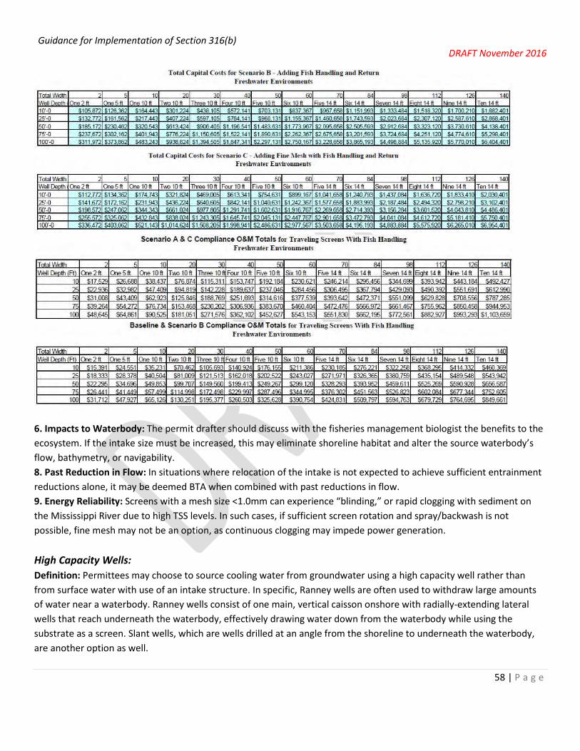
Guidance for Implementation of Section 316(b) DRAFT November 2016
58 | P a g e
6. Impacts to Waterbody: The permit drafter should discuss with the fisheries management biologist the benefits to the ecosystem. If the intake size must be increased, this may eliminate shoreline habitat and alter the source waterbody’s flow, bathymetry, or navigability. 8. Past Reduction in Flow: In situations where relocation of the intake is not expected to achieve sufficient entrainment reductions alone, it may be deemed BTA when combined with past reductions in flow. 9. Energy Reliability: Screens with a mesh size <1.0mm can experience “blinding,” or rapid clogging with sediment on the Mississippi River due to high TSS levels. In such cases, if sufficient screen rotation and spray/backwash is not possible, fine mesh may not be an option, as continuous clogging may impede power generation. High Capacity Wells: Definition: Permittees may choose to source cooling water from groundwater using a high capacity well rather than from surface water with use of an intake structure. In specific, Ranney wells are often used to withdraw large amounts of water near a waterbody. Ranney wells consist of one main, vertical caisson onshore with radially-extending lateral wells that reach underneath the waterbody, effectively drawing water down from the waterbody while using the substrate as a screen. Slant wells, which are wells drilled at an angle from the shoreline to underneath the waterbody, are another option as well.

Guidance for Implementation of Section 316(b) DRAFT November 2016
59 | P a g e
1. Numbers and Types of Organisms Entrained: Elimination of the surface water intake would eliminate entrainment, and the 316(b) regulations would no longer apply to the facility. 2. Particulate Emissions/Other Pollution: None expected. 3. Land Availability: Minimal land required. 4. Remaining Useful Plant Life: 5. Social Costs and Benefits: Vary depending on well capacity. Filtration of water through the substrate may reduce the level of water treatment required, thereby saving money. 6. Impacts to Waterbody: Discuss the ecosystem benefits of entrainment elimination with regional fisheries management biologist. Other benefits may result from retirement of the intake structure, involving changes to flow patterns and bathymetry. In stratified waterbodies, concerns may exist regarding accelerated turnover/mixing of the thermal layers. 7. Thermal Discharge: Groundwater may be cooler than surface water, lowering the temperature of the cooling water effluent. 10. Water Consumption: If a facility retires their surface water intake in order to install high capacity wells onsite, the wells will typically be near the original source/receiving waterbody. Because groundwater will be withdrawn near the waterbody and will be returned to the waterbody, surface water elevations should not be significantly affected. Wells withdrawing more than 70 gpm will need to obtain approval from the Water Use Section of the DNR (http://dnr.wi.gov/topic/wells/highcapacity.html). Additionally, if the well will be located in the Great Lakes Basin, a Water Use Permit will be required (http://dnr.wi.gov/topic/WaterUse/permits.html). A general permit is available for withdrawals less than 1 MGD. Unit Retirement: 1. Numbers and Types of Organisms Entrained: Unit retirement reduces the amount of water required for cooling and thereby reduces entrainment proportionally. i.e. if a unit retirement reduces water withdrawn by 25% on an AIF basis, entrainment will also be reduced by 25%. If a unit retires but still withdraws water, credit for entrainment reduction may not be given. 2. Particulate Emissions/Other Pollution: Particulate emissions and wastewater pollution will be reduced. 3. Land Availability: Not typically a concern. 4. Remaining Useful Plant Life: Unit retirement should not be proposed as BTA if the plant has remaining life, unless the permittee suggests it. 5. Social Costs and Benefits: Unit retirement should not be proposed as BTA unless the permittee suggests it. 6. Impacts to Waterbody: Discuss the ecosystem benefits of entrainment reduction with regional fisheries management biologist. Other benefits or impacts may result from the intake flow reduction, involving changes to flow patterns and bathymetry. 7. Thermal Discharge: A unit’s thermal discharge is typically eliminated after unit retirement. 8. Past Reduction in Flow: Entrainment reduction through unit retirement may be recognized for any unit retired after October 14, 2004. 9. Energy Reliability: Power generation will be reduced as a result of unit retirement. 10. Water Consumption: Water consumed through forced evaporation will be decreased.

Guidance for Implementation of Section 316(b) DRAFT November 2016
60 | P a g e
No Additional Controls Necessary: This should only be considered when all other BTA options are unavailable and entrainment levels are very low. If more than 5% of the waterbody’s mean annual flow is withdrawn for cooling on an AIF basis, some controls will typically be warranted. Entrainment survival studies that demonstrate high survival rates may also be used to justify a determination that no additional controls are necessary. Entrainment survival may be fairly high if moderate temperatures are maintained in-plant. If no entrainment survival study is submitted, 100% entrainment mortality should be assumed.

Guidance for Implementation of Section 316(b) DRAFT November 2016
61 | P a g e
4.5 Making BTA Determinations for New Units at Existing Facilities
Under the EPA rule, a new unit at an existing facility, where the facility withdraws or will withdraw more than 2 MGD when the new unit begins operating, will have impingement mortality and entrainment requirements similar to the requirements for a new facility under the Phase I rule. Under the rule, a new unit (as defined at § 125.92(u)) is required to have a flow limited to that which is commensurate with a closed-cycle recirculating system as it would be applied to the new unit. The final rule also includes an alternative approach (similar to Track II in Phase I), in which a facility could comply with the new unit standards by demonstrating that the technologies and operational measures employed will reduce the level of adverse environmental impact from any cooling water intake structure used to supply cooling water to the new unit to a comparable level to that achievable by implementing a closed-cycle recirculating system as defined at § 125.92(c)(1).
EPA has defined “new unit” to mean a stand-alone unit at an existing facility, the construction of which commences after the effective date of EPA’s final rule (October 14, 2014); consists of only a stand-alone unit constructed at an existing facility; and that does not otherwise meet the definition of a new facility at § 125.83. A stand-alone unit is a new, separate unit that is constructed at an existing facility. A new unit may have its own dedicated cooling water intake structure, or may use an existing or modified cooling water intake structure. A unit that is constructed at a standalone location at an existing facility would be considered a new unit, regardless of any plans to retire any other unit at the facility.
Electric Generators:
The EPA rule defines a new unit at an existing facility as a newly built, standalone unit that is constructed at an existing facility and that does not meet the definition of a new facility. An existing unit that is repowered or undergoes significant modifications (such as where the turbine and condenser are replaced) is not considered a new unit.
Manufacturers:
At manufacturing facilities that generate electricity onsite, the above definition of new units at existing electric generating facilities generally applies. However, some manufacturers employ different industrial processes than an electric generator and therefore have different industrial equipment (including cooling systems) and may have opportunities to re-use cooling water that a power plant does not. Therefore, these situations should be examined on a case by case basis.
Examples of New Units at Manufacturers:
• A unit that is constructed at a stand-alone location at an existing facility (either adjacent to existing units or on newly acquired or developed property) regardless of any plans to retire any other unit at the facility in the future.)
• A unit that is constructed adjacent to an existing unit for the same industrial activity (such as expanding the production output by building a second unit as a stand-alone unit next to the existing unit).
Once the permittee has submitted all of the information required in § 122.21(r), the Department is required to make BTA determinations for impingement and entrainment for that facility based on that information in the next permit

Guidance for Implementation of Section 316(b) DRAFT November 2016
62 | P a g e
reissuance. In cases where a permittee will have to make changes at their facility in order to meet impingement and/or entrainment standards, Department can establish a compliance schedule in the reissued permit to allow time for this to be accomplished. The rule also allows entrainment and impingement compliance to occur sequentially, where necessary.
The EPA rule establishes a BTA standard, for both impingement mortality and entrainment, for new units at existing facilities. Under this standard, new units at existing facilities are subject to requirements similar to the section 316(b) requirements for new facilities subject to the previously promulgated Phase I rule. However, the new unit requirements apply only to the volume of cooling water used by the new unit, or to the cooling water intake structures used by the new unit. The new unit requirements do not apply to the rest of the existing facility. Any alternative must achieve a level of performance as close as practicable to the requirements of § 125.94(e)(1) or (2).
Also, the new unit entrainment standards do not apply to certain water withdrawals including:
1. Cooling water used by manufacturing facilities for contact cooling purposes. 2. Portions of those water withdrawals for auxiliary cooling uses totaling less than 2 MGD. 3. Any volume of cooling water withdrawals used exclusively for makeup water at existing closed-cycle
recirculating systems. 4. Any quantity of emergency back-up water flows. Furthermore, as is the case for existing units, obtaining cooling
water from a public water system, using reclaimed water from wastewater treatment plants, or desalination plants, or using recycled process wastewater effluent as cooling water does not constitute use of a cooling water intake structure.
One of two compliance alternatives must be applied to meet national BTA standards for impingement mortality and entrainment for new units at existing facilities (40 CFR 125.94(e)). An intake structure that supplies cooling water exclusively for operation of a closed cycle recirculating system (a wet or dry cooling tower) that meets the definition at § 125.92(c)(1) automatically meets this new unit standard. Otherwise, the permittee must demonstrate that it has installed, operates, and maintains technology or other control measures that reduce the level of adverse environmental impact to a level comparable to that which would be achieved through flow reductions commensurate with the use of a closed-cycle recirculating system. Under this alternative, the permittee must be able to demonstrate that entrainment mortality reductions are equivalent to > 90% of the reduction that could be achieved through compliance with the first alternative mentioned above.
One option that reduces entrainment is flow reduction, where the permittee installs a technology or operates in a manner to reduce or eliminate the amount of water being withdrawn. Reduced volumes of cooling water produce a corresponding reduction in entrainment. Some flow reduction technologies referenced in the EPA rule include variable frequency drives and variable speed pumps, seasonal operation or seasonal flow reductions, unit retirements, use of alternate cooling water sources, water reuse, and closed-cycle cooling systems. Other technologies that may be used to further reduce impingement and entrainment would be similar to those listed in this guidance for existing facilities (see pgs. 37).
The EPA rule allows the Department to establish alternative requirements if compliance with the new unit standards would result in costs wholly out of proportion to the costs EPA considered in establishing the requirements or would result in significant adverse impacts on local air quality, local water resources other than impingement or entrainment,

Guidance for Implementation of Section 316(b) DRAFT November 2016
63 | P a g e
threatened and endangered species, or local energy markets. However, any alternative must achieve a level of performance as close as practicable to the requirements of § 125.94(e)(1) or (2).
To see costs EPA considered, see the Economic Analysis for the rule: https://www.epa.gov/sites/production/files/2015-05/documents/cooling-water_phase-4_economics_2014.pdf .
Monitoring Requirements for New Units
Monitoring is required to demonstrate compliance with the requirements of § 125.94(e), as follows:
1. The Department may establish monitoring requirements for impingement, impingement mortality, and entrainment of the fish and shellfish species identified in the Source Water Baseline Biological Characterization data required by 40 CFR 122.21(r)(4). Monitoring methods used must be consistent with those used for the Source Water Baseline Biological Characterization at 40 CFR 122.21(r)(4).
2. If the facility is subject to the requirements of § 125.94(e)(1) or (2), the frequency of flow monitoring and
velocity monitoring must be daily and must be representative of normal operating conditions. Flow monitoring must include measuring cooling water withdrawals, make-up water, and blowdown volume. The Department may require additional monitoring necessary to demonstrate compliance with § 125.94(e).
3. If the facility is subject to the requirements of § 125.94(e)(2), monitoring must be done to demonstrate
achievement of reductions commensurate with a closed cycle recirculating system. Entrainable organisms must be monitored at a proximity to the intake that is representative of the entrainable organisms in the absence of the intake structure. Latent entrainment mortality must also be monitored in front of the intake structure. Mortality after passing the cooling water intake structure must be counted as 100 percent mortality unless the permittee can demonstrate that the mortality for each species is < 100%. Monitoring must be representative of the cooling water intake when the structure is in operation. In addition, sufficient samples must be collected to allow for calculation of annual average entrainment levels of all life stages of fish and shellfish.
Specific monitoring protocols and frequency of monitoring will be determined by the Department. These monitoring frequencies must be followed for at least two years after the initial permit issuance. After that time, the Department may approve a request for less frequent monitoring in the remaining years of the permit term and in subsequent permit reissuances. The monitoring must measure the total count of entrainable organisms or density of organisms, unless the Department approves of a different metric for such measurements. In addition, the actual intake flow (AIF) must be measured for each intake at the same time as the samples of entrainable organisms are collected. The Department may require additional monitoring necessary to demonstrate compliance with § 125.94(e).
4. The Department may require additional monitoring for impingement or entrainment at the cooling water intake
structure used by a new unit including, but not limited to, the following: (i) The Department may require additional monitoring if there are changes in operating conditions at
the facility or in the source waterbody that warrant a re-examination of the operational conditions identified at 40 CFR 122.21(r).
(ii) The Department may require additional monitoring for species not subject to the BTA requirements for impingement mortality at § 125.95(c). Such monitoring requirements will be determined by the Department on a site specific basis.

Guidance for Implementation of Section 316(b) DRAFT November 2016
64 | P a g e
5. Visual or remote inspections. The permittee must either conduct visual inspections or employ remote
monitoring devices during the period the cooling water intake structure is in operation. These inspections must be done at least weekly to ensure that any technologies operated to comply with § 125.94 are maintained and operated to function as designed including those installed to protect Federally-listed threatened or endangered species or designated critical habitat. Alternate procedures may be establish if this requirement is not feasible (e.g., an offshore intake, velocity cap, or during periods of inclement weather).
6. Request for reduced monitoring. For facilities that are subject to § 125.94(c)(7) and where the facility’s cooling
water intake structure does not directly or indirectly affect Federally listed threatened and endangered species, or designated critical habitat, the owner or operator of the facility may request to have monitoring reduced after the first full permit term of monitoring.
7. Additional monitoring related to Federally-listed threatened and endangered species and designated critical
habitat at existing facilities. Additional monitoring may be required when Federally listed threatened or endangered species or designated critical habitat is impacted.
4.6 Making BTA Determinations Using Best Professional Judgment
EPA’s 2014 rule establishes requirements under section 316(b) for all existing facilities that withdraw > 2 MGD from waters of the U.S. and that use > 25% of their intake water for cooling. For existing facilities that fall below either of these thresholds, the Department is required to make best technology available (BTA) determinations using best professional judgment, according to 40 CFR 125.90(b):
Cooling water intake structures not subject to requirements under §§ 125.94 through 125.99 or subparts I or N of this part must meet requirements under section 316(b) of the CWA established by the Director on a case-by-case, best professional judgment (BPJ) basis.
Facilities that fall into category 1, as described on page 15, may also need an interim BTA determination to be made using best professional judgment, while they are collecting the information necessary to comply with application requirements in the new 2014 federal rule. According to the USEPA NPDES Permit Writers’ Manual (EPA-833-B-96-003, 12/96), BPJ-based limits are technology-based limits derived on a case-by-case basis for non-municipal (industrial) facilities. BPJ limits are established whenever effluent limit guidelines are not available for the pollutant in question. BPJ is defined as “the highest quality technical opinion developed by a regulator after consideration of all reasonably available and pertinent information”. The authority for BPJ is contained in Section 402(a)(1) of the Clean Water Act (CWA), which authorizes the regulator to issue a permit containing “such conditions as the Administrator determines are necessary to carry out the provisions of this Act.” This is further discussed at s. 40 CFR 125.3(c)(2).
Regulations at s. 40 CFR 125.3 state that permits developed on a case-by case basis under s. 402(a)(1) of the CWA must consider (i) The appropriate technology for the category of point sources of which the applicant is a member, based upon available information; and (ii) Any unique factors relating to the applicant. The USEPA NPDES Permit Writers’ Manual provides factors that should be considered when developing BPJ conditions, including: 1) the total cost of application of technology in relation to effluent reduction benefits, 2) the age of equipment and facilities, 3) the process

Guidance for Implementation of Section 316(b) DRAFT November 2016
65 | P a g e
employed, 4) engineering aspects of the application of various types of control techniques, 5) process changes, and 6) non-water quality environmental impacts. Staff should consider each of these factors when establishing BPJ-based conditions in permits.
Because it is broad in scope, BPJ allows considerable flexibility in establishing permit conditions. However, lack of specificity also places a burden on staff to show that their BPJ decision is reasonable and based on a thorough review of available information. Therefore, it is important to provide thorough documentation of the basis for the BPJ decision.
The following list provides some general guidelines that staff may use when making a BTA determination using their BPJ, on a case-by-case basis. Staff should be able to determine, in most cases, that BTA is present at an existing facility (whether issued an individual or general permit) if it meets the following criteria:
1. The facility is a point source that uses water from one or more surface water intake structures. This includes structures operated by an independent supplier that provides cooling water to the permittee by any sort of contract or other arrangement;
2. The water intake structure(s) withdraws from waters of the state; 3. The facility-wide design intake flow (DIF) for all water intake structures is < 2 MGD (all intake water, cooling and
non-cooling, is included in the determination of whether this DIF threshold is met) 1 OR < 25% of the total water withdrawn is used exclusively for cooling purposes (water from a public water system, treated effluents, process water, gray water, wastewater, reclaimed water, or water used in a manufacturing process before or after it is used for cooling is not considered cooling water for the purposes of this determination) 1;
4. Each water intake structure has a maximum design intake velocity of 0.5 feet per second (fps) 1 OR a maximum actual intake velocity of 0.5 fps, demonstrated via measured or calculated values which show the maximum intake velocity as water passes through the entrance to the intake system, measured perpendicular to the opening, does not exceed 0.5 fps.2
5. AND ONE OR MORE OF THE FOLLOWING: a. The total water withdrawn (actual intake flow) is < 5% of the mean annual flow of the river on which the
facility is located (if on a river or stream) OR the total quantity of the water withdrawn is restricted to a level necessary to maintain the natural thermal stratification or turnover patterns (where present) except in cases where the disruption is beneficial (if on a lake or reservoir) 2, 3, 4
b. The facility operates at < 8% capacity utilization rate (see definition in Section 1) or at full capacity only for portions of days during a few months or less on an annual basis.2 If located in a spawning area, the period of water intake operation must not correspond with times when spawning is occurring (depending on species present, usually between April – October).
c. The facility operates a closed-cycle recirculating system that only requires make-up water (with > 3 cycles of concentration on at least a daily basis). Cycles of concentration (COC) can be measured as the ratio of chloride levels in the recirculated water or blowdown relative to the chloride levels in the source water, or makeup water; or the make-up water volume divided by the blowdown volume (provided there aren’t other water loses); or the blowdown water conductivity divided by the make-up water conductivity.
1 Design intake flow < 2 MGD, < 25% used for cooling, and design intake velocity would need to be demonstrated based on existing data at the time of application. No additional monitoring or demonstration of flow rates, percent used for cooling, or intake velocity would be necessary during the permit term, as long as no significant changes were made that would change these values.

Guidance for Implementation of Section 316(b) DRAFT November 2016
66 | P a g e
2 Actual intake velocity, intake volume (for determining % mean annual flow of the river), days of intake use, and cycles of concentration would need to be demonstrated based on existing data at the time of application, but should also be verified (through calculation estimates or monitoring) during the permit term.
3 Special attention should be paid to situations where there is the potential for cumulative impacts due to multiple intakes in the same area.
4 EPA has indicated that 30% of facilities on freshwater streams or rivers have actual intake flows greater than 5% the mean annual flow of their source waters (79 FR 48402).
The Department believes that existing facilities which fit into the criteria above pose low to no risk for causing an adverse environmental impact and therefore, in the absence of other site-specific factors which cause concern, a determination can be made that BTA is present at these locations. There may be other scenarios (technologies, operations, locations) that meet the BTA standard in some cases; staff should use their judgment to determine when these circumstances exist.
Permit language should be included which reflects the BTA determination that has been made. Permit language should also be included that requires the permittee to report actual intake flow velocity, intake volume, days of intake use, cycles of concentration, or other applicable criteria that should be verified on a regular basis.
Staff should include a detailed description of existing intakes and cooling water systems in individual permit fact sheets to document the current situation. The fact sheet should contain discussion of the BTA determination, specifically why the intake and installed technologies represent BTA. Also, individual permits should include language which specifies (at a minimum) that the permittee will continue to operate the intake as approved and notify the Department prior to making any changes. General permits should contain language which allows coverage only for those facilities that can demonstrate that BTA is present (as defined using the criteria listed above) or will be achieved during the term of the permit. If staff decide that the existing intake does not represent BTA, they will need to include a reasonable compliance schedule to allow time for making the necessary changes to meet BTA.
A detailed evaluation of proposed technologies should be done before a new intake is installed to make sure that the best available technologies are implemented. Department staff should perform a thorough evaluation of all proposed new intakes.
Because smaller facilities (< 2 MGD) are believed to have less potential to cause adverse environmental impact, these BTA determinations can typically be exempt from review by DNR fisheries, USFWS, and USEPA. If permit staff have questions or concerns in specific situations, fisheries biologists and/or water quality biologists may be consulted to confirm that problems are not present. An NHI Portal check should still be completed to confirm whether or not T&E species are present.
Existing facilities with intake volumes < 2 MGD or < 25% used exclusively for cooling only need to submit information specified in 40 CFR 122.21(r) 2, 3, 5, and 8, with their permit application (or request for coverage, if a general permit). See application requirements for existing facilities on pg. 21.

Guidance for Implementation of Section 316(b) DRAFT November 2016
67 | P a g e
5. General FAQ Multiple Intakes
1. Are BTA determinations made for all intakes as a whole or each intake individually? The permittee may choose whether they wish to have the regulations applied on an intake-by-intake basis or on a whole-facility basis.
2. If a facility has multiple intakes, and one of them is not used for any sort of cooling process, does a BTA determination need to be made for that non-cooling intake? The federal regulations only apply to cooling water intake structures, so no BTA needs to be made using the federal regulations. However, our state statute applies to all intake structures, so a BPJ BTA determination should be made.
Entrainment Sampling Location 3. Where should entrainment sampling occur? The preferred location is immediately after the intake structure
screen. However, the biodensity of the intake may be stratified, so sampling at multiple depths may be necessary. If safety concerns make sampling at the intake impossible, sampling could be moved to another location before the condenser. Sampling after the condenser (i.e. at the discharge) should be avoided if possible in order to eliminate potential for loss or damage of entrained organisms.
Velocity Point of Compliance
4. Where should the 0.5 fps through-screen velocity standard be applied? This should be applied at the point at which water is withdrawn from a water of the state, even if there is no screen at this point. The reason for this is to prevent entrapment (fish may be unable to escape a forebay if the forebay inlet velocity is >0.5 fps).
Application Materials for Facilities < 2 MGD DIF
5. A permittee withdraws < 2 MGD DIF. What application materials does the permittee need to submit? Permittees that withdraw < 2 MGD DIF need to submit the materials specified in 40 CFR 122.21 (r) (2-5, 7, and 8), as 40 CFR 122.21(r) requires all existing facilities to submit (r)(2-3) and the applicable provisions of (4-8). There is no need to submit (r)(6), as the Impingement Mortality BTA does not need to be selected from the seven compliance options. Additionally, permittees with small withdrawal rates should note that (r)(4) and (7) only require the submittal of previously conducted studies; new studies need not be conducted unless special circumstances warrant them.
Monitoring and Reporting Conditions for Permittees with Alternate Schedules
6. A permittee is granted an alternate schedule and will be receiving an interim BTA determination. Should the monitoring and reporting conditions of 40 CFR 125.96-97 (weekly inspections, annual certification statement, etc.) be included in the permit? Yes, an interim BTA determination delays the use of 40 CFR 125.94(c) and (d) for use in determining the BTA. It does not delay implementation of the entire rule.
Calculations of AIF and % Used for Cooling Purposes
7. When does the period of calculation for 25% used for cooling and 125 MGD AIF begin? AIF and Percent Used for Cooling Purposes should be reported for a period of three years preceding the permit application before 10/14/2019. After this date, AIF and Percent Used for Cooling Purposes should be reported for a period of five years preceding the permit application.

Guidance for Implementation of Section 316(b) DRAFT November 2016
68 | P a g e
8. What if I am under the 125 MGD AIF threshold now, but this changes shortly before the permit application is due? Facilities that expect to be near the 125 MGD AIF threshold may want to assume they will be over the threshold and compile all necessary information. If they are over the threshold at the time of application, the Department will expect that all necessary application materials be submitted.
De minimis
9. Are fragile species considered for de minimis? Yes, while they are not counted in the Impingement Technology Performance Optimization Study, fragile species are counted and considered when evaluating whether or not an intake structure qualifies for the de minimis provision.
10. What is a rough number of “fish impinged per year” that qualifies for de minimis? A de minimis determination is a site-specific determination, so such a number may vary from waterbody-to-waterbody. At this point, the Department does not have sufficient data available to release a definitive threshold number for each waterbody in the state.
11. What else is considered in evaluating a de minimis request? Conversions of impingement rates into number of Age One-Equivalent organisms and seasonal fluctuations in impingement rates may be considered. Additionally, facilities that employ only trash racks as an exclusion technology will typically not qualify for de minimis.
Fish Return Design
12. Will fish returns be regulated outfalls in WPDES Permits? No, so long as they are not comingled with wastewater used for any industrial purposes.
Peer Review Confidentiality
13. Can the identity of peer reviewers be confidential? No, in order to verify the qualifications of the peer reviewer, identities should be publically available and resumes/CVs should be submitted to the Department.
14. Must all comments within the peer review be attributed to an identified peer reviewer? The Department recognizes that there may exist a tendency to be lenient in order to protect a relationship between the peer reviewer and the permittee. If this is the case, the peer reviewer may work with the Department to find a solution that satisfies both the need for public transparency as well as effective, unfiltered review. If such an agreement is not reached, all comments should be attributed to the peer reviewer who posed them. In all cases, the content of all comments should be publically available, and peer reviewers should not comment on topics outside of their areas of expertise.

Guidance for Implementation of Section 316(b) DRAFT November 2016
69 | P a g e
6. References
Baker, Jim, Tom Feely, Glenn Comisac, Jack Burns, and Wayne Micheletti. “Wet Versus Dry Cooling Towers.” Seminar Transcript, Cooling Technology Institute Educational Seminar, February 28, 2001. http://www.cti.org/downloads/CTI-2001-EducationalSeminar.pdf?_sm_au_=iMVStsM0n50tV88H.\
“Benefits Analysis for the Final Section 316(b) Existing Facilities Rule.” U.S. Environmental Protection Agency. (May 2014).
Carter, Mike. “Variable-Frequency Drives.” Presentation. http://www.alliantenergy.com/wcm/groups/wcm_internet/@int/@ae/documents/application/mdaw/mtez/~edisp/113410.pdf.
Coutant, Charles C., “Hydraulic Patterns and Fish Responses Make In-River, Cylindrical Intake Screens Fish Friendly,” Energy Northwest, EPRI 316(b) Conference, Charlotte, November 10, 2015.
“Energy Penalty Analysis of Possible Cooling Water Intake Structure Requirements on Existing Coal-Fired Power Plants.” U.S, Department of Energy, Office of Fossil Energy (2002).
Environmental Protection Agency. “National Pollutant Discharge Elimination System—Final Regulations To Establish Requirements for Cooling Water Intake Structures at Existing Facilities and Amend Requirements at Phase I Facilities; Final Rule.” Federal Register 79, no. 158 (August, 5 2014).
Garrett Jr., William E. and Justin B. Mitchell, “Biological Optimization of Traveling Water Screens at Plant Barry, AL,” Alabama Power Company Presentation, EPRI 316(b) Conference, Charlotte, November 10, 2015.
Laboratory Evaluations of an Aquatic Filter Barrier (AFB) for Protecting Early Life Stages of Fish, EPRI, Palo Alto, CA: 2002. 1005534.
“Technical Development Document for the Final Section 316(b) Existing Facilities Rule.” U.S. Environmental Protection Agency. (May 2014).
“Technical Development Document for the Final Section 316(b) Phase II Existing Facilities Rule.” U.S. Environmental Protection Agency. (February 12, 2004).
Young, John and William Dey, “Variable-Speed Pumps: When, Why, & How,” ASA Analysis & Communication Inc. Presentation, EPRI 316(b) Conference, Charlotte, November 10, 2015.

Guidance for Implementation of Section 316(b) DRAFT November 2016
70 | P a g e
Appendix A: Map of Facilities Current as of September 2016. Does not include general permittees. Key: Purple = Power Plant Red = Pulp and Paper Mills Green = Other Large Dot = >125 MGD AIF Small Dot = <125 MGD AIF

Guidance for Implementation of Section 316(b) DRAFT November 2016
71 | P a g e
Appendix B: Template Permit Language for BTA Determinations (>2MGD DIF and >25% of intake water used for cooling)
In the “Influent” section of SWAMP enter Sampling Point 701 (or 901 if the 701 is already used for influent monitoring) to create a location for all the requirements related to the cooling water intake. To change the permit’s section title from “Influent” to “Cooling Water Intake Requirements”, SWAMP will have to be unlocked so that it can be edited.
There are no monitoring requirements associated with Sampling Point 701, but the permit drafter will need to create an empty table in order to generate the section. If the permit will contain monitoring requirements for the intake water for the collection of background data that should be included under Sampling Point 601 (receiving water) in the surface water section.
For examples of permits that have been issued with cooling water intake requirements, refer to the We Energies Port Washington Generating Station (WI-0000922-08-0) for intake improvements that have already been installed, and Domtar Paper Company Rothschild (WI-0026042-08-0) where an interim BTA determination was made. The Manitowoc Public Utilities Permit (WI-0027189-07-0) contains an example of a final BTA determination (<125 MGD AIF).
The cooling water intake description for the fact sheet may be similar to the outline of what is included in the permit but should include greater detail and further explanations that are not appropriate for the permit. The permit will state what the Department’s BTA determination is without going into the details of how that decision was reached. The fact sheet must provide the rationale for the BTA determination with a description of how the impingement and entrainment performance standards are complied with. A supplemental attachment to the fact sheet may be necessary if the BTA discussion becomes too lengthy or if details from biological studies need to be provided as part of the documentation.
WPDES Permit Template for Section 1 - “Cooling Water Intake Requirements”
1 Cooling Water Intake Requirements
1.1 Sampling Point(s)
Sampling Point Designation
Sampling Point Number
Sampling Point Location, Waste Type/Sample Contents and Treatment Description (as applicable)
701 [ENTER NAME OF WATERBODY WHERE WATER IS WITHDRAWN] cooling water intake structure. Monitor intake flow on days of operation.
70X EMERGENCY cooling water intake structure requirements. Monitor intake flow on days of operation.

Guidance for Implementation of Section 316(b) DRAFT November 2016
72 | P a g e
1.2 BTA Determinations and Monitoring Requirements 1.2.1 Sampling Point 701 - [ENTER Name of Intake #1]
Monitoring Requirements and Limitations
Parameter Limit Type Limit and Units
Sample Frequency
Sample Type
Notes
Flow Rate MGD Daily Continuous
Intake Water used for Cooling
% Flow Daily Continuous
1.2.1.1 Authority to Operate (Cooling Water Intake Description)
The permittee shall at all times properly operate and maintain all water intake facilities. The permittee shall give advance notice to the Department of any planned changes in the location, design, operation, or capacity of the intake structure. The permittee is authorized to use the [ENTER name of water intake if it has one] cooling water intake system which consists of the following:
[Note to Permit Drafter: Provide a general description of the water intake system using a bulleted list as shown below. In the fact sheet more details can be provided that describe the major components. Below is example language (but there may be more details here than necessary if the fact sheet documents this as well).]
• Location: [ENTER location of intake]. • General Description: [ENTER a general description of water intake technology, whether it’s planned or installed]. • Major Components: [ENTER major components of the intake such as cylindrical wedge-wire screens, trash rack,
vertical traveling screens, backwash system, and fish return system]. • Maximum Design Intake Flow (DIF): [ENTER maximum DIF in MGD (passed on pump capacity)]. • Design Intake Flow-Through Velocity: [ENTER Design Intake Flow-Through Velocity in feet/second (Velocity = DIF
/ [screen face area * percent open area]). If the 0.5 feet/second flow rate is the technology utilized for impingement mortality, the location where compliance is determined should be the point at which water is withdrawn from a water of the state].
1.2.1.2 BTA Determination
[Note to Permit Drafter: Describe the conclusion of the BTA determination in the permit. State whether the cooling water intake is (1) approved as BTA, (2) is conditionally approved, or (3) is not BTA. The paragraph below is an example of an approved BTA prior to the October 14, 2014 effective date of the 316(b) federal regulations. The details on how the decision was reached should be explained in the fact sheet.]
The Department believes that the [ENTER water intake technology] cooling water intake, as described above in subsection 1.2, represents BTA for minimizing adverse environmental impact in accordance with the requirements in section 283.31(6), Wis. Stats. and section 316(b) of the Clean Water Act.
[Include the following paragraph for interim BTA determinations:]

Guidance for Implementation of Section 316(b) DRAFT November 2016
73 | P a g e
Note: This is an interim BTA determination based on the Department’s February 2, 2009 guidance for evaluating cooling water intake structures using best professional judgment. Because the [ENTER Facility Name] permit expired before the October 14, 2014 effective date of the new federal regulations for existing facilities, those requirements are not applicable until the next permit reissuance. Nevertheless, for informational purposes this permit includes references to the new federal regulations in 40 CFR Parts 122 and 125, and some of the requirements are included at the Department’s discretion to begin implementation of the new rule in this permit.
1.2.1.3 Intake-specific Conditions
[Include any intake-specific conditions necessary for implementation of the BTA. For example, include optimal screen rotation speed and frequency, spray nozzle pressure, and return trough flow rate as requirements for modified traveling screens. For barrier nets, include the months during which the nets should be deployed. For closed cycle cooling, include any necessary restrictions on the minimum number of cycles of concentration. For 0.5 fps maximum actual intake velocity, include a limit in the table in 1.2.1 with a flow limit derived from the 0.5 fps maximum velocity, screen open area, and wetted screen area at 7Q10 flow heights. Etc.]
Note: Repeat Section 1.2.1 for each intake at the facility. Once all intakes have been covered, continue on to the Emergency Intake Section.
1.2.X Sampling Point 702 - EMERGENCY INTAKE
Monitoring Requirements and Limitations
Parameter Limit Type Limit and Units
Sample Frequency
Sample Type
Notes
Flow Rate MGD Daily Continuous
Intake Water used for Cooling
% Flow Daily Continuous
1.2.X.1 Authority to Operate and Use Limitations
The emergency cooling water intake structure described below is authorized for use but has use restrictions as listed below. Monitoring and reporting are required.
[ENTER a detailed description of the emergency water intake, where it’s located, intake technologies used if any, size, design intake flow, and flow through velocity ______.]
[ENTER appropriate requirements for the emergency intake. Restrictions on when it may be used should be included _____.]
1.2.X.2 BTA Determination

Guidance for Implementation of Section 316(b) DRAFT November 2016
74 | P a g e
The emergency cooling water intake is included as a component of the water intake system technologies, and is also considered to be BTA. Because of its limited use on an emergency basis its environmental impact is minimized. (Note: this determination fits most cases. Change to “not BTA” if you have concerns about the emergency intake)
1.2.X.3 Monitoring and Reporting
The permittee shall notify the Department within 5 days after any use of the emergency cooling water intake system. The date and the duration during which the intake is open shall be monitored and reported. The permittee shall provide notification to the DNR field contact.
1.3 Intake Structure Standard Requirements
The following requirements and provisions apply to all water intake structures identified as sampling points in Section 1.1.
1.3.1 Future BTA Determinations for Cooling Water Intake Structure(s)
BTA determinations for entrainment mortality and impingement mortality at cooling water intake structures will be made in each permit reissuance, in accordance with 40 CFR §125.90-98. In subsequent permit reissuance applications, the permittee shall provide all the information required in 40 CFR §122.21(r).
[Note to Permit Drafter: Include the next paragraph if the facility’s cumulative design intake flow is (DIF) is >2 MGD and the actual intake flow (AIF) is <125 MGD. Note: If an alternatives analysis is on hand from a previous reissuance and is still relevant, there is no need to include this paragraph]:
Also include an alternatives analysis report for compliance with the entrainment BTA requirements with the permit application. This alternatives analysis for entrainment BTA shall examine the options for compliance with the entrainment BTA requirement and propose a candidate entrainment BTA to the Department for consideration during its next BTA determination. The analysis must, at least narratively, address and consider the factors listed in 40 CFR §125.98 (f) (2) and may consider the factors listed in 40 CFR § 125.98 (f) (3). The analysis must evaluate, at a minimum, closed-cycle recirculating systems, fine mesh screens with a mesh size of 2mm or smaller, variable speed pumps, water reuse or alternate sources of cooling water, and any additional technology identified by the Department at a later date.
Exemptions from some permit application requirements are possible in accordance with 40 CFR §125.95(c) and §125.98(g), where information already submitted is sufficient. If an exemption is desired, a request for reduced application material requirements must be submitted at least 2 years and 6 months prior to permit expiration. Past submittals and previously conducted studies may satisfy some or all of the application material requirements.
Note: The Department is in the process of promulgating ch. NR 111, Wis. Adm. Code, on cooling water intake structures. The objective of ch. NR 111 is to incorporate federal requirements for cooling water intake structures into the state’s administrative code. If ch. NR 111 is promulgated prior to the expiration of this permit, the permittee may be subject to ch. NR 111 application requirements for the next permit reissuance.
1.3.2 Entrainment Monitoring
[Note to Permit Drafter: This section is only necessary for facilities that have design intake flows (DIF) > 2 MGD and actual intake flows (AIF) <125 MGD and that do not have relevant, historical entrainment data on hand. Also include a schedule for entrainment monitoring in the compliance schedules section, if this section is included.

Guidance for Implementation of Section 316(b) DRAFT November 2016
75 | P a g e
For facilities with AIF>125 MGD, two years of entrainment characterization is already required under 40 CFR 122.21(r)(9), and this is already specified in “Future BTA” (above). For such facilities, there is no need for further entrainment characterization unless special circumstances warrant it. For facilities with DIF <2 MGD, there is no need to include this section unless special circumstances warrant entrainment monitoring.]
Monthly (once per month) entrainment monitoring is required during the last year of the permit ([ENTER last year of permit: ____]) for the months of [ENTER months of spawning, primary reproduction, and peak abundance (i.e the months when eggs and larvae are present in the vicinity of the intake, as identified by the regional fisheries biologist. A default period of April-September should be used in the absence of information from the regional biologist)] (Note: Biweekly sampling may be warranted and is suggested for one or two months during the expected peak abundance month(s)).
This entails quantification and identification of all life stages of entrained fish and shellfish, including eggs, to the lowest taxon possible. The entrainment sampling point may not be at or immediately preceding the discharge.
1.3.3 Impingement Mortality Monitoring
[Note to Permit Drafter: Enter impingement monitoring as needed. A minimum of one year of impingement mortality monitoring (minimum of monthly) should be required unless the permittee has relevant historical data on hand or intends to comply with the IM BTA through use of closed cycle cooling, 0.5 fps, or an offshore velocity cap. This is because some baseline impingement mortality data is needed in order to make a de minimis determination or establish a baseline against which the impingement technology performance optimization study results can be compared. This section is required for facilities operating modified traveling screens or a system of technologies or complying with the 24% performance standard as IM BTA.] [Any impingement monitoring required should be included in the “Schedule” section of the permit.]
Impingement mortality monitoring is required on a [CHOOSE ONE: monthly or biweekly or weekly or daily] basis during the last year of the permit, [ENTER last year of permit: ____]. This entails quantification and identification of all life stages of fish and shellfish, to the lowest taxon possible, that are impinged against the [CHOOSE the point of withdrawal from a water of the state: trash rack or bar screen or (ENTER other impinging structure _______)].
1.3.4 Visual or Remote Inspections
The permittee shall conduct a weekly visual inspection or employ a remote monitoring device during periods when the cooling water intake is in operation. The inspection frequency shall be weekly to ensure the intakes are maintained and operated to function as designed.
1.3.5 Reporting Requirements for Cooling Water Intake
The permittee shall adhere to the reporting requirements listed below:
[Note to Permit Drafter: Include the following subsection on Discharge Monitoring Reports if the permittee is required to conduct compliance monitoring for impingement and entrainment. If compliance monitoring is waived then no reporting applies.]

Guidance for Implementation of Section 316(b) DRAFT November 2016
76 | P a g e
1.3.5.1 Discharge Monitoring Reports (DMRs)
Report the results of the compliance monitoring for entrainment and impingement mortality on the monthly DMR in the General Remarks section.
1.3.5.2 Annual Certification Statement and Report
Submit an annual certification statement signed by the authorized representative with information on the following, no later than January 31st for the previous year:
• Certification that water intake structure technologies are being maintained and operated as set forth in this permit, or a justification to allow a modification of the practices. Include a summary of the required Visual or Remote Inspections.
• If there are substantial modifications to the operation of any unit that impacts the cooling water withdrawals or operation of the water intake structure, provide a summary of those changes.
• If the information contained in the previous year’s annual certification is still applicable, the certification may simply state as such.
[Note to Permit Drafter: Include the following bullet if applicable.]
• Compliance monitoring results for impingement mortality and entrainment mortality.
1.3.6 Intake Screen Discharges and Removed Substances
Floating debris and accumulated trash collected on the cooling water intake trash rack shall be removed and disposed of in a manner to prevent any pollutant from the material from entering the waters of the State pursuant to s. NR 205.07 (3) (a), Wis. Adm. Code. However, the permittee may discharge backwash from the traveling water screens if present and discharge to [ENTER designated outfall where discharge occurs _____]. These backwashes may contain fine materials that originated from the intake water source such as sand, silt, small vegetation or aquatic life.
1.3.7 Endangered Species Act
Nothing in this permit authorizes take for the purpose of a facility’s compliance with the Endangered Species Act. Refer to 40 CFR §125.98 (b) (1) and (2).

Guidance for Implementation of Section 316(b) DRAFT November 2016
77 | P a g e
WPDES Fact Sheet Template for Section 1 - “Cooling Water Intake Requirements” For Interim/Best Professional Judgment BTA Determinations
1 Cooling Water Intake Requirements
1.1 Sampling Point(s) Sampling Point Designation
Sampling Point Number
Sampling Point Location, Waste Type/Sample Contents and Treatment Description (as applicable)
701 [ENTER NAME OF WATERBODY WHERE WATER IS WITHDRAWN] cooling water intake structure requirements. Monitor intake flow on days of operation.
70X EMERGENCY cooling water intake structure requirements. Monitor intake flow on days of operation.
1.2 BTA Determinations and Monitoring Requirements 1.2.1 Sampling Point 701 - [ENTER Name of Intake #1]
Monitoring Requirements and Limitations
Parameter Limit Type Limit and Units
Sample Frequency
Sample Type
Notes
Flow Rate MGD Daily Continuous
Intake Water used for Cooling
% Flow Daily Continuous
1.2.1.1 Authority to Operate (Cooling Water Intake Description)
The permittee shall at all times properly operate and maintain all water intake facilities. The permittee shall give advance notice to the Department of any planned changes in the location, design, operation, or capacity of the intake structure. The permittee is authorized to use the water intake system which consists of the following:
• Location: [ENTER location of intake]. • Source Waterbody Information: [For rivers/streams, ENTER Q7,10 Flow and Mean Annual Harmonic Flow Rate.
For lakes, ENTER the volume of the lake and any information on stratification/turnover (turnover dates, depth of thermocline, etc.). Include the depth of water in front of the intake at Q7,10 flows/low water levels]
Guidance for Implementation of Section 316(b) DRAFT November 2016
78 | P a g e
• General Description: [ENTER a general description of water intake technology (proposed or installed), including screen dimensions, screen open area, etc.].
• Major Components: [ENTER major components of the intake such as cylindrical wedge-wire screens, trash rack, vertical traveling screens, closed cycle cooling, backwash system, fish return system].
• Maximum Design Intake Flow (DIF): The maximum design intake flow (DIF) is [ENTER DIF, based on pump capacity] MGD (___ cfs), which is equivalent to [ENTER =100*DIF/Q7,10] % of the Q7,10. This is based upon the intake’s pump capacity, not counting redundant or emergency pumps.
• Maximum Design Intake Velocity:The through-screen design intake velocity at the point of withdrawal is [ENTER =Q/(A*P); Q = DIF, A = inlet width*depth of water at Q7,10 or low water mark in lakes, P = the proportion of the screen that is open area (as a decimal). Show the calculation] feet/second (___ cfs /[__ ft screen width * __ ft water depth (at 7Q10) * ___ open area proportion]).
• Actual Intake Flow: The actual intake velocity is [ENTER average daily intake flow over the last three years, including days of zero flow. For permits issued after 2019, use 5 years of data] MGD (___ cfs), which is equivalent to [ENTER 100*AIF/Q7,10] % of the Q7,10.
• Actual Intake Velocity: The through-screen actual intake velocity at the trash rack is [ENTER =Q/(A*P); Q = AIF, A = inlet width*depth of water at Q7,10 or low water mark in lakes, P = the proportion of the screen that is open area (as a decimal). Show the calculation] feet/second (___ cfs/[___ ft screen width * __ ft water depth (at 7Q10) * ___ open area proportion]). These figures are based on the annual average withdrawal rate during ____ - _____.
• Percent Used for Cooling: [ENTER the percent of water withdrawn that is used for cooling purposes. Do not count water that is both used for cooling and is recycled for another use.]
• Nearby Intakes: Provide the name, location, and AIF of nearby intakes (all within a 5 mile radius on the same waterbody, or the nearest intake outside that range).
• Emergency Intake Structure: [ENTER “There is no emergency intake at the facility” or provide details on the intake structure and how often it is used.]
1.2.1.2 BTA Determination
[For permits expired before 10/14/14, include the following paragraph:]
The permittee submitted its application for permit reissuance before the October 14, 2014 effective date of the Final Regulations on Cooling Water Intake Structures (40 CFR 125.90-98 and 122.21 (r)). As a result and pursuant to 40 CFR 125.98(b)(6), the Best Technology Available (BTA) determination for this permit issuance is made using the Department’s best professional judgment (BPJ) rather than the final federal regulations.
[For permits expiring after 10/14/14 that were granted an alternate schedule, include the following paragraph:]
The Department granted the permittee an alternate schedule for submission of the materials required in 40 CFR 122.21(r). As a result and pursuant to 40 CFR 125.98(b)(5), the Best Technology Available (BTA) determination for this permit issuance is made using the Department’s best professional judgment (BPJ) rather than the final federal regulations.
[Include for all BPJ BTA determinations:]
Best professional judgment BTA determinations are made using the Department’s 2009 Guidance for Evaluating Intake Structures Using Best Professional Judgment. For existing intake structures, the guidance advises that intakes deemed BTA should fulfill at least two of the following six criteria:
• The intake design flow velocity is < 0.5 fps. (The point of withdrawal is [ENTER point at which water is withdrawn from a water of the state (typically the trash rack)]. The intake design velocity at this point is [ENTER design intake velocity] fps).

Guidance for Implementation of Section 316(b) DRAFT November 2016
79 | P a g e
• The facility’s intake structure includes a wedgewire screen. (The facility [ENTER “does” or “does not”]t utilize a wedgewire screen).
• The intake’s design flow is <5% of the Q7,10 of the source water. (The facility’s design flow is [ENTER =100 * DIF/Q7,10] % of the Q7,10).
• The facility uses a closed-cycle cooling system for ≥95% of their cooling needs or has reduced intake flow ≥95% compared to once-through cooling. (The facility [CHOOSE “does” or “does not”] use a closed-cycle cooling system, [ENTER “and/but it has (not)”] demonstrated a 95% reduction in flow.)
• The facility has data that shows impingement mortality (and entrainment, if applicable) has been/will be reduced 80-95% (60-90% for entrainment) compared to a once-through cooling system with 3/8” traveling screens. ([ENTER whether or not the facility has done so. If so, provide a justification below in “Review of Past Data”]).
• There is biological data demonstrating that: 1) the source waterbody does not include threatened or endangered species in the vicinity of the intake, and 2) there are no known aquatic life and water quality problems partly or solely due to the presence or operation of the intake structure. ([ENTER whether or not such biological data exists. If it does, summarize the data and provide a quote from the regional DNR biologist’s assessment below in “Review of Past Data.”]).
The facility meets [ENTER how many criteria are met] of the above criteria. The Department therefore believes that the Thilmany Mill’s intake structure [If two or more criteria are met, ENTER “does.” If one or zero criteria are met, ENTER “does not”] represent BTA for minimizing adverse environmental impact in accordance with the requirements in section 283.31 (6), Wis. Stats. and section 316 (b) of the Clean Water Act.
Review of Past Data [If biological data is available to support any of the criteria is section 1.3, summarize it here and include the regional DNR biologist’s review of the data.]
1.2.X Emergency Intake BTA (Best Technology Available) Determination
Monitoring Requirements and Limitations
Parameter Limit Type Limit and Units
Sample Frequency
Sample Type
Notes
Flow Rate MGD Daily Continuous
Intake Water Used for Cooling
% Flow Daily Continuous
1.2.X.1 Emergency Cooling Water Intake
The emergency cooling water intake is included as a component of the water intake system technologies, and is also considered to be BTA. Because of its limited use on an emergency basis its environmental impact is minimized.
1.2.X.2 Monitoring and Requirements
[Provide a justification of any restrictions or monitoring placed upon use of the emergency intake]

Guidance for Implementation of Section 316(b) DRAFT November 2016
80 | P a g e
1.3 Intake Structure Standard Requirements
1.3.1 Future BTA
Again, note that the determination in section 1.3 is an interim BTA determination made using the Department’s BPJ. BTA determinations made in future permit reissuances will be made in accordance with the requirements of the federal regulations in 40 CFR 125.90-98, based upon the materials submitted by the permittee through 40 CFR 122.21 (r).
[Note to Permit Drafter:
For facilities with actual intake flows (AIF) > 2 MGD and <125 MGD, include the following paragraph:]
In addition, the Department is requiring the submittal of an Alternatives Analysis Report for compliance with the entrainment BTA requirements. This additional submittal is required because, in making an entrainment BTA determination in future permit issuances, the Department must consider the factors listed in 40 CFR 125.98 (f) (2) and may consider the criteria considered in 40 CFR 125.98 (f) (3). Even after receiving the application materials required in 40 CFR 122.21 (r), the Department does not expect to have sufficient information necessary to make an entrainment determination. Therefore, the Department requires the permittee to complete an Alternatives Analysis Report, in which the permittee 1) addresses narratively, at the least, the criteria in 40 CFR 125.98 (f) (2), 2) may address the criteria in 40 CFR 125.98 (f) (3), and 3) propose a technology, management practice, operational measure, or some combination thereof as a candidate for the Department’s entrainment BTA determination. The analysis must evaluate, at a minimum, closed-cycle recirculating systems, fine mesh screens with a mesh size of 2mm or smaller, variable speed pumps, water reuse or alternate sources of cooling water, and any additional technology identified by the Department at a later date.
Also note that the state is in the process of promulgating ch. NR 111, Wis. Adm. Code, on cooling water intake structures. The objective of ch. NR 111 is to incorporate federal requirements for cooling water intake structures into the state’s administrative code. If ch. NR 111 is promulgated prior to the expiration of this permit, the permittee may be subject to ch. NR 111 application requirements for the next permit reissuance.
1.3.2 Entrainment Characterization
[Note to Permit Drafter:
For facilities with actual intake flows (AIF) > 2 MGD and <125 MGD that do not have historical, relevant entrainment data on hand, include the monthly entrainment monitoring requirements and a schedule in the Schedules section.
Monthly entrainment characterization is required because, in making an entrainment BTA determination in future permit issuances, the Department must consider “numbers and types of organisms entrained,” pursuant to 40 CFR 125.98 (f) (2) (i). In order to consider this, the Department must have some entrainment characterization data. The Department selected monthly data collection spanning one primary period of reproduction in order to minimize the burden on the permittee while capturing the seasonal variations in entrainment. The period of April to September was identified by the Department as the period of primary reproduction. A minimal number of eggs and larvae are expected to be present in the water column outside of this time period.
Entrainment characterization entails quantification and identification of all life stages of entrained fish and shellfish, including eggs, to the lowest taxon possible. The Department suggests sampling at the traveling water screens.
1.3.3 Impingement Monitoring

Guidance for Implementation of Section 316(b) DRAFT November 2016
81 | P a g e
[If impingement monitoring is required, include a justification for it. e.g. the permittee plans to apply for de minimis or comply using a modified traveling screen, system of technologies, or the impingement mortality performance standard, so data is required.]
1.3.4 Visual or Remote Inspections
The permittee is required to conduct visual or remote inspections of the intake structure at least weekly during periods of operation, pursuant to 40 CFR 125.96 (e).
1.3.5 Reporting Requirements
The permittee is required to submit an annual certification statement and report, pursuant to 40 CFR 125.97 (c).
1.3.6 Intake Screen Discharges and Removed Substances
Floating debris and accumulated trash collected on the cooling water intake trash rack shall be removed and disposed of in a manner to prevent any pollutant from the material from entering the waters of the State pursuant to s. NR 205.07 (3) (a), Wis. Adm. Code.
1.3.7 Endangered Species Act
40 CFR §125.98 (b) (1) requires the inclusion of this provision in all permits subject to 316(b) requirements. Contact the state Natural Heritage Inventory (NHI) staff with inquiries regarding incidental take of state-listed threatened and endangered species and the US Fish and Wildlife Service with inquiries regarding incidental take of federally-listed threatened and endangered species.

Guidance for Implementation of Section 316(b) DRAFT November 2016
82 | P a g e
WPDES Fact Sheet Template for Section 1 - “Cooling Water Intake Requirements” For Final BTA Determinations made under 40 CFR 125.90-98
1 Cooling Water Intake Requirements
1.1 Sampling Point(s) Sampling Point Designation
Sampling Point Number
Sampling Point Location, Waste Type/Sample Contents and Treatment Description (as applicable)
701 [ENTER NAME OF WATERBODY WHERE WATER IS WITHDRAWN] cooling water intake structure requirements. Monitor intake flow on days of operation.
70X EMERGENCY cooling water intake structure requirements. Monitor intake flow on days of operation.
1.2 BTA Determinations and Monitoring Requirements 1.2.1 Sampling Point 701 - [ENTER Name of Intake #1]
Monitoring Requirements and Limitations
Parameter Limit Type Limit and Units
Sample Frequency
Sample Type
Notes
Flow Rate MGD Daily Continuous
Intake Water used for Cooling
% Flow Daily Continuous
1.2.1.1 Cooling Water Intake Description
[Enter Name of Intake] consists of the following:
• Location: [ENTER location of intake]. • Source Waterbody Information: [For rivers/streams, ENTER Q7,10 Flow and Mean Annual Harmonic Flow Rate.
For lakes, ENTER the volume of the lake and any information on stratification/turnover (turnover dates, depth of thermocline, etc.). Include the depth of water in front of the intake at Q7,10 flows/low water levels]
• General Description: [ENTER a general description of water intake technology (proposed or installed), including screen dimensions, screen open area, etc.].

Guidance for Implementation of Section 316(b) DRAFT November 2016
83 | P a g e
• Major Components: [ENTER major components of the intake such as cylindrical wedge-wire screens, trash rack, vertical traveling screens, closed cycle cooling, backwash system, fish return system].
• Maximum Design Intake Flow (DIF): The maximum design intake flow (DIF) is [ENTER DIF, based on pump capacity] MGD (___ cfs), which is equivalent to [ENTER =100*DIF/Q7,10] % of the Q7,10. This is based upon the intake’s pump capacity, not counting redundant or emergency pumps.
• Maximum Design Intake Velocity:The through-screen design intake velocity at the point of withdrawal is [ENTER =Q/(A*P); Q = DIF, A = inlet width*depth of water at Q7,10 or low water mark in lakes, P = the proportion of the screen that is open area (as a decimal). Show the calculation] feet/second (___ cfs /[__ ft screen width * __ ft water depth (at 7Q10) * ___ open area proportion]).
• Actual Intake Flow: The actual intake velocity is [ENTER average daily intake flow over the last three years, including days of zero flow. For permits issued after 2019, use 5 years of data] MGD (___ cfs), which is equivalent to [ENTER 100*AIF/Q7,10] % of the Q7,10.
• Actual Intake Velocity: The through-screen actual intake velocity at the trash rack is [ENTER =Q/(A*P); Q = AIF, A = inlet width*depth of water at Q7,10 or low water mark in lakes, P = the proportion of the screen that is open area (as a decimal). Show the calculation] feet/second (___ cfs/[___ ft screen width * __ ft water depth (at 7Q10) * ___ open area proportion]). These figures are based on the annual average withdrawal rate during ____ - _____.
• Percent Used for Cooling: [ENTER the percent of water withdrawn that is used for cooling purposes. Do not count water that is both used for cooling and is recycled for another use.]
• Nearby Intakes: [Provide the name, location, and AIF of nearby intakes (all within a 5 mile radius on the same waterbody, or the nearest intake outside that range).]
• Emergency Intake Structure: [ENTER “There is no emergency intake at the facility” or provide details on the intake structure and how often it is used.]
1.2.1.2 BTA Determination
1.2.1.2.1 Impingement Mortality BTA Determination
[Choose the method of compliance with the IM BTA standard below. Delete others:]
[CCRS:] The permittee has selected to comply with the impingement mortality standard in 40 CFR 125.94 (c) (1) by implementing a closed cycle recirculating system. This intake structure feeds into a cooling system that meets the definition of a closed-cycle recirculating system in 40 CFR 125.92 (c), as demonstrated by the following: [Identify whether the system is a wet, dry, or hybrid cooling tower or a cooling pond. If the system is a cooling pond, ensure the definition in 40 CFR 125.92 (c) (1 or 2) is satisfied.] [Discuss minimization of cooling tower makeup flows. Power plants typically operate at 3-6 cycles of concentration while manufacturers operate at 9+ COC].
[0.5 feet per second through-screen design velocity:] The permittee has selected to comply with the impingement mortality standard in 40 CFR 125.94 (c) (2) by implementing a through-screen design velocity of 0.5 feet per second. This was assessed at the point at which water is withdrawn from a surface water of the state using the following equation:
Design Velocity = [Pump Capacity Flow Rate] _ [Screen % Open Area] [Screen Wetted Area at 7Q10 Elevations]
A pump capacity of ____, a screen % open area of _____, and a screen wetted area of ______ (depth at 7Q10 = _____, screen width = _____), yields a through screen design velocity of _______. (Pump capacity should be the DIF; it should not include redundant, back-up, or emergency pumps)
[0.5 feet per second through-screen actual velocity:] The permittee has selected to comply with the impingement mortality standard in 40 CFR 125.94 (c) (3) by implementing a through-screen actual velocity of 0.5 feet per second. This

Guidance for Implementation of Section 316(b) DRAFT November 2016
84 | P a g e
will be assessed at the point at which water is withdrawn from a surface water of the state, using real-time flow monitoring data. The 0.5 fps limitation has been converted to a flow limitation using the following equation:
Design Velocity = [Actual Instantaneous Flow Rate] _ [Screen % Open Area] [Screen Wetted Area at 7Q10 Elevations]
Instantaneous Flow Limit = 0.5 feet/second * [Screen % Open Area] * [Screen Wetted Area at 7Q10]
The permit includes a continuous flow rate monitoring and a _____ MGD daily maximum limitation of the instantaneous flow rate.
[Note: The above can be adjusted if the permittee intends to use real-time water elevations. In such a case, the permit should require reporting of the daily maximum instantaneous intake flow rate, water depth, and screen wetted area).]
[Existing offshore velocity cap:] The permittee has selected to comply with the impingement mortality standard in 40 CFR 125.94 (c) (4) by utilizing the existing offshore velocity cap. The intake meets the definition of an existing offshore velocity cap, as demonstrated by the following: (1) the velocity cap is ____feet offshore (>800 ft), (2) the intake was constructed on _________ (before October 14, 2014), (3) the intake creates a horizontal velocity pattern, and (4) the intake uses bar screens to exclude large aquatic organisms.
[Modified Traveling Screen:] The permittee has selected to comply with the impingement mortality standard in 40 CFR 125.94 (c) (5) by utilizing a modified traveling screen. [Give an overview of the specific modified traveling screen technology to be used]. This technology meets the definition of a modified traveling screen at 40 CFR 125.92 (s), as demonstrated by the following: (1) the screen includes collection buckets that reduce turbulence to aquatic life, (2) a guard rail or barrier prevents loss of fish from the collection system, (3) screen panels are made of [pick one: smooth woven mesh, drilled mesh, molded mesh, or similar materials] that protect fish from scaling or other abrasive injury, (4) the screens will be continuously or near-continuously rotated, (5) a low pressure wash or vacuum will be used to remove fish prior to a high pressure spray to remove debris from the screens, (6) a fish handling and return system with adequate flow is present and will not promote predation or re-impingement of fish and does not include a large vertical drop.
A two-year impingement mortality performance optimization study is required in association with this technology. See 40 CFR 122.21 (r) (6) for details and communicate with the DNR permit drafter and compliance engineer regarding a study plan.
The following permit conditions have been included to ensure that the technology performs as intended [elaborate on conditions.. samples provided below:]:
• Continuous rotation
• Set flow rate in fish return trough
• Max pressure on fish removal spray system
[System of technologies, management practices, and/or operational measures:] The permittee has selected to comply with the impingement mortality standard in 40 CFR 125.94 (c) (6) by implementing a system of technologies, management practices, and/or operational measures. [Describe the proposed system and how each component has been translated into an expected reduction in impingement mortality. The expected reduction should achieve a rate of at most 24% impingement mortality. See the section on systems of technologies in section 4.4.1 of the guidance for more details.]
A two-year impingement mortality performance optimization study is required in association with this technology. See 40 CFR 122.21 (r) (6) for details and communicate with the DNR permit drafter and compliance engineer regarding a study plan.
[Impingement mortality standard of 24%:] The permittee has chosen to comply with the impingement mortality standard of 24% for all non-fragile and non-nuisance species. This will be demonstrated by monthly monitoring of impingement mortality, including latent mortality measured after at least 18 hours. Compliance with the standard will be

Guidance for Implementation of Section 316(b) DRAFT November 2016
85 | P a g e
based on comparison of the 24% limit to a 12-month rolling average of impingement mortality data. See 40 CFR 125.94 (c) (7) for more details.
[Capacity Utilization Rate <8%:] The facility has demonstrated, based on power generation data over the last 24 months, that it operates at a capacity utilization rate of _____. Because this is less than 8% and because the facility does not operate its pumps (or operates them at a very low rate – e.g. <0.25fps through screen velocity) during periods of shutdown or standby, the Department has determined that the facility is exempt from the impingement mortality standard in 40 CFR 125.94 (c). See 40 CFR 125.94 (c) (12) for more details.
[De minimis:] The Department has reviewed impingement data from the facility and determined that the impingement rate is de minimis. Therefore, the facility is exempt from the impingement mortality standard in 40 CFR 125.94 (c). See 40 CFR 125.94 (c) (11) for more details. [See pages 45-46 and 71 of the guidance for more on de minimis. Explain how the number of fish impinged relates to other facilities and why it is low enough that no additional controls are warranted. If impingement rates spike during a certain time of the year, seasonal deployment of barrier nets may be warranted].
1.2.1.2.1 Entrainment BTA Determination
__________ has been identified by the Department as the best technology available for minimizing entrainment at this intake structure. The following technologies were evaluated: (1) closed-cycle recirculating systems, (2) fine mesh screens with a mesh size of 2mm or smaller with a safe return mechanism, (3) variable speed pumps, (4) water reuse or alternate sources of cooling water, and (5) wells or Ranney Collectors [adapt the list in any way necessary. These are simply recommended technologies for examination]. Each technology was evaluated using the criteria listed in 40 CFR 125.98 (f) (2) and, where relevant, the criteria listed in 40 CFR 125.98 (f) (3). See the tables below for analyses:
[Fill in the below tables with evaluations of each technology using the criteria provided and, where relevant, the criteria in 40 CFR 125.98 (f) (3): entrainment impacts on the waterbody, thermal discharge impacts, credit for reductions in flow associated with the retirement of unites occurring within the ten years preceding 10/14/14, impacts on the reliability of energy delivery within the immediate area, impacts on water consumption, and availability of water for reuse as cooling water. If factors are weighted, do include the weighting factor, narratively or quantitatively.]
Closed-cycle Recirculating System
Numbers and types of organisms entrained, including T&E species and designated critical habitat
Impact of changes in particulate emissions or other pollutants
Land availability
Remaining useful plant life
Quantified and qualitative social benefits
[Any other factors in 40 CFR 125.98 (f) (3) that are considered. Add more rows as

Guidance for Implementation of Section 316(b) DRAFT November 2016
86 | P a g e
necessary.]
Variable Speed Pumps
Numbers and types of organisms entrained
Particulate emissions or other pollutants
Land availability
Remaining useful plant life
Quantified and qualitative social benefits
[Any other factors in 40 CFR 125.98 (f) (3) that are considered. Add more rows as necessary.]
Water Reuse or Alternate Sources of Water
Numbers and types of organisms entrained
Particulate emissions or other pollutants
Land availability
Remaining useful plant life
Quantified and qualitative social benefits
[Any other factors in 40 CFR 125.98 (f) (3) that are considered. Add more rows as necessary.]
Wells or Ranney Collectors
Numbers and types of organisms entrained

Guidance for Implementation of Section 316(b) DRAFT November 2016
87 | P a g e
Particulate emissions or other pollutants
Land availability
Remaining useful plant life
Quantified and qualitative social benefits
[Any other factors in 40 CFR 125.98 (f) (3) that are considered. Add more rows as necessary.]
Review of Past Data [If biological data is available to support any of the criteria is section 1.3, summarize it here and include the regional DNR biologist’s review of the data.]
1.2.X Emergency Intake BTA (Best Technology Available) Determination
Monitoring Requirements and Limitations
Parameter Limit Type Limit and Units
Sample Frequency
Sample Type
Notes
Flow Rate MGD Daily Continuous
Intake Water Used for Cooling
% Flow Daily Continuous
1.2.X.1 Emergency Cooling Water Intake
The emergency cooling water intake is included as a component of the water intake system technologies, and is also considered to be BTA. Because of its limited use on an emergency basis its environmental impact is minimized. [Calculate the percent of time the emergency cooling water intake is operated. If <8% CUR, use this as a justification for impingement mortality BTA. The low usage rate should also be used to make a determination that entrainment impacts are minimized, and the intake represents the BTA for entrainment reduction.]
1.2.X.2 Monitoring and Requirements
[Provide a justification of any restrictions or monitoring placed upon use of the emergency intake]
1.3 Intake Structure Standard Requirements

Guidance for Implementation of Section 316(b) DRAFT November 2016
88 | P a g e
1.3.1 Future BTA
This is a final BTA determinations made in accordance with the requirements of the federal regulations in 40 CFR 125.90-98, based upon the materials submitted by the permittee through 40 CFR 122.21 (r). Future BTA determinations will be made under the same regulations, but the permittee may request that some application materials be waived under 40 CFR 125.95 (c) and 40 CFR 125.98 (g).
[Note to Permit Drafter:
For facilities with actual intake flows (AIF) > 2 MGD and <125 MGD, include the following paragraph. Note: If an alternatives analysis is on hand from a previous reissuance and is still relevant, there is no need to include this paragraph:]
In addition, the Department is requiring the submittal of an Alternatives Analysis Report for compliance with the entrainment BTA requirements. This additional submittal is required because, in making an entrainment BTA determination in future permit issuances, the Department must consider the factors listed in 40 CFR 125.98 (f) (2) and may consider the criteria considered in 40 CFR 125.98 (f) (3). Even after receiving the application materials required in 40 CFR 122.21 (r), the Department does not expect to have sufficient information necessary to make an entrainment determination. Therefore, the Department requires the permittee to complete an Alternatives Analysis Report, in which the permittee 1) addresses narratively, at the least, the criteria in 40 CFR 125.98 (f) (2), 2) may address the criteria in 40 CFR 125.98 (f) (3), and 3) propose a technology, management practice, operational measure, or some combination thereof as a candidate for the Department’s entrainment BTA determination. The analysis must evaluate, at a minimum, closed-cycle recirculating systems, fine mesh screens with a mesh size of 2mm or smaller, variable speed pumps, water reuse or alternate sources of cooling water, and any additional technology identified by the Department at a later date.
Also note that the state is in the process of promulgating ch. NR 111, Wis. Adm. Code, on cooling water intake structures. The objective of ch. NR 111 is to incorporate federal requirements for cooling water intake structures into the state’s administrative code. If ch. NR 111 is promulgated prior to the expiration of this permit, the permittee may be subject to ch. NR 111 application requirements for the next permit reissuance.
1.3.2 Entrainment Characterization
[Note to Permit Drafter:
For facilities with actual intake flows (AIF) > 2 MGD and <125 MGD that do not have historical, relevant entrainment data on hand, include the monthly entrainment monitoring requirements below and a schedule in the Schedules section. Facilities with flow >125 MGD AIF or <2 MGD will not typically need this section in the fact sheet:
Monthly entrainment characterization is required because, in making an entrainment BTA determination in future permit issuances, the Department must consider “numbers and types of organisms entrained,” pursuant to 40 CFR 125.98 (f) (2) (i). In order to consider this, the Department must have some entrainment characterization data. The Department selected monthly data collection spanning one primary period of reproduction in order to minimize the burden on the permittee while capturing the seasonal variations in entrainment. The period of April to September was identified by the Department as the period of primary reproduction. A minimal number of eggs and larvae are expected to be present in the water column outside of this time period.
Entrainment characterization entails quantification and identification of all life stages of entrained fish and shellfish, including eggs, to the lowest taxon possible. The Department suggests sampling at the traveling water screens.

Guidance for Implementation of Section 316(b) DRAFT November 2016
89 | P a g e
1.3.3 Impingement Monitoring
[If impingement monitoring is required, include a justification for it. e.g. the permittee plans to apply for de minimis or comply using a modified traveling screen, system of technologies, or the impingement mortality performance standard, so data is required to establish a baseline impingement mortality rate.]
1.3.4 Visual or Remote Inspections
The permittee is required to conduct visual or remote inspections of the intake structure at least weekly during periods of operation, pursuant to 40 CFR 125.96 (e).
1.3.5 Reporting Requirements
The permittee is required to submit an annual certification statement and report, pursuant to 40 CFR 125.97 (c).
1.3.6 Intake Screen Discharges and Removed Substances
Floating debris and accumulated trash collected on the cooling water intake trash rack shall be removed and disposed of in a manner to prevent any pollutant from the material from entering the waters of the State pursuant to s. NR 205.07 (3) (a), Wis. Adm. Code.
1.3.7 Endangered Species Act
40 CFR §125.98 (b) (1) requires the inclusion of this provision in all permits subject to 316(b) requirements. Contact the state Natural Heritage Inventory (NHI) staff with inquiries regarding incidental take of state-listed threatened and endangered species and the US Fish and Wildlife Service with inquiries regarding incidental take of federally-listed threatened and endangered species.

Guidance for Implementation of Section 316(b) DRAFT November 2016
90 | P a g e
Appendix C: Compliance Schedule Template for Installation of BTA(s) Once BTA determinations have been made in accordance with 40 CFR 125.94 (c) and (d) (not interim BTA determinations), the permit should include a compliance schedule for installation of the BTA(s) for reducing impingement mortality and entrainment. A sample schedule is provided below, although dates may vary depending on the scale of the project and the start of construction season. If possible, try to avoid requiring construction to commence in winter. If the installation will be intensive and requires more than one year, a progress report on the construction should be required at the midpoint of construction. Time between compliance milestones should not exceed 1 year.
Required Action Due Date Plans and Specifications: The permittee shall submit to the Department plans and specifications for the installation(s) of BTA(s) for impingement mortality and entrainment reduction, as specified in the site-specific determination of BTA(s) for impingement mortality and entrainment reduction in section 1 of the permit. While no formal approval is required before commencement of construction under 281.41, Wis. Stats., the Department will review the plans and specifications to ensure consistency with the site-specific BTA determination.
12 months
Commence Construction of BTA: The permittee shall initiate construction or installation of the BTA(s) for impingement mortality and entrainment reduction, as specified in the site-specific determination of BTA(s) for impingement mortality and entrainment reduction in section 1 of the permit.
18 months
Impingement Technology Performance Optimization Study Plan (NOT ALWAYS NECESSARY*): If the permittee has chosen to comply with the Impingement Mortality Standard specified in 40 CFR 125.94 (c) (5 or 6) (modified traveling screens or system of technologies), the permittee shall submit a study plan for the Impingement Technology Performance Optimization Study.
27 months
Entrainment Reduction Verification Sampling (NOT ALWAYS NECESSARY**): The permittee shall submit a plan for entrainment characterization sampling for one period of primary reproduction, larval recruitment, and peak abundance, as identified by the Department, in order to verify reduction in entrainment.
27 months
Complete Construction of BTA: The permittee shall complete construction or installation(s) of the BTA(s) for impingement mortality and entrainment reduction, as specified in the site-specific determination of BTA for impingement mortality and entrainment reduction in section 1 of the permit.
30 months
Commence Entrainment Reduction Verification Sampling (**) and/or Impingement Technology Performance Optimization Study Plan (*) (NOT ALWAYS NECESSARY): The permittee shall commence the study(ies) in accordance with the approved study plans.
30 months
Entrainment Reduction Verification Sampling (NOT ALWAYS NECESSARY**): The permittee shall complete entrainment characterization sampling for one period of primary reproduction, larval recruitment, and peak abundance, as identified by the Department, in order to verify reduction in entrainment.
48 months
Impingement Technology Performance Optimization Study Plan (NOT ALWAYS NECESSARY*): If the 54 months

Guidance for Implementation of Section 316(b) DRAFT November 2016
91 | P a g e
permittee has chosen to comply with the Impingement Mortality Standard specified in 40 CFR 125.94 (c) (5 or 6) (modified traveling screens or system of technologies), the permittee shall submit a study plan for the Impingement Technology Performance Optimization Study. *The Impingement Technology Performance Optimization Study (ITPOS) (see 40 CFR 122.21 (r) (6)) must be conducted if the permittee selects to comply with the Impingement Mortality BTA Standard by using a modified traveling screen or a system of technologies. If this is not the case, there is no need to require the ITPOS. **The entrainment reduction verification sampling may be warranted in instances such as outfall relocation, where the actual reduction in entrainment is difficult to predict. For fine mesh screens with safe handling and return, latent mortality of entrainable organisms should be measured as well. Situations that do not warrant entrainment reduction verification sampling are those where flow reduction is used, such as unit retirement, water reuse, variable speed pumps, or cooling towers. Instead, flow data will suffice to represent entrainment reduction.