Embed Size (px)
Citation preview
FP/FR1200/2000 Series
Analogue Addressable Fire Panels, Repeaters and Emulators
Reference Guide
Revision 8-0 / April 2005 For panel firmware v8.0 and higher


Aritech is a GE-Interlogix brand.
www.aritech.com
COPYRIGHT
© 2003 GE Interlogix B.V.. All rights reserved. GE Interlogix B.V. grants the right to reprint this manual for internal use only. GE Interlogix B.V. reserves the right to change information without notice.
TRADEMARK ACKNOWLEDGEMENT
ARCNET is a registered trademark of Datapoint Corporation
SAFETY
To ensure safe operation and to keep the product safe, the information, cautions and warnings in this manual must be heeded. Failure to comply with the precautions or with specific warnings elsewhere in this manual violates the safety standard of design, manufacture and intended use of this product. The manufacturer assumes no liability for the customer’s failure to comply with these requirements.

Reference Guide 3
CONTENTS
1 Introduction............................................................................................................................................ 7
2 Panel Definition ..................................................................................................................................... 8 2.1 Description .................................................................................................................................... 8 2.2 Special features ............................................................................................................................ 8 2.3 User friendliness ........................................................................................................................... 8 2.4 Powerful maintenance features .................................................................................................... 8 2.5 Networking .................................................................................................................................... 9 2.6 General features ........................................................................................................................... 9 2.7 Standard I/O facilities .................................................................................................................... 9 2.8 Mechanical data .......................................................................................................................... 10
3 Panel Operation................................................................................................................................... 11 3.1 LED indications and controls....................................................................................................... 11 3.2 General indicators ....................................................................................................................... 12 3.3 Controls ....................................................................................................................................... 14 3.4 Sounders..................................................................................................................................... 14 3.5 Fire brigade ................................................................................................................................. 15 3.6 Other ........................................................................................................................................... 15 3.7 Zone indicators............................................................................................................................ 16 3.8 LCD and keypad ......................................................................................................................... 17 3.9 Software features of the FP1200 ................................................................................................ 18
4 LCD Screen Operation ........................................................................................................................ 19 4.1 Start-up screens.......................................................................................................................... 19 4.2 Alarm line .................................................................................................................................... 20 4.3 Valid entries line.......................................................................................................................... 21 4.4 Status line.................................................................................................................................... 22 4.5 System status menu.................................................................................................................... 22
5 Programming Menus........................................................................................................................... 23 5.1 Access to main menu.................................................................................................................. 23
5.1.1 Main menu ................................................................................................................... 24 5.1.2 System menu............................................................................................................... 26 5.1.3 Configuration menu ..................................................................................................... 27 5.1.4 Hardware configuration 1............................................................................................. 28 5.1.5 Version......................................................................................................................... 30 5.1.6 Site Version ................................................................................................................. 31 5.1.7 Hardware configuration 2............................................................................................. 32 5.1.8 Board information ........................................................................................................ 33 5.1.9 Memory allocation 1..................................................................................................... 34 5.1.10 Memory allocation 2..................................................................................................... 35 5.1.11 Panel ID ....................................................................................................................... 36 5.1.12 Global Repeater ID ...................................................................................................... 37 5.1.13 Local Repeater ID........................................................................................................ 38 5.1.14 Communication menu.................................................................................................. 39 5.1.15 Port Setup.................................................................................................................... 40 5.1.16 Network menu.............................................................................................................. 43 5.1.17 Panels .......................................................................................................................... 44 5.1.18 Local repeaters ............................................................................................................ 45 5.1.19 Global repeaters .......................................................................................................... 46 5.1.20 Modem menu............................................................................................................... 47 5.1.21 Modem alarm report 1 ................................................................................................. 48 5.1.22 Modem alarm report 2 ................................................................................................. 49 5.1.23 Modem maintenance ................................................................................................... 50 5.1.24 Modem setup 1 ............................................................................................................ 51 5.1.25 Modem setup 2 ............................................................................................................ 52 5.1.26 Modem setup 3 ............................................................................................................ 53
4 Reference Guide
5.1.27 Pager Configuration..................................................................................................... 54 5.1.28 Pager Configuration 2.................................................................................................. 55 5.1.29 LON Devices................................................................................................................ 56 5.1.30 LON Devices Setup 1 .................................................................................................. 57 5.1.31 LON Devices Setup 2 .................................................................................................. 59 5.1.32 LON Devices Setup 3 .................................................................................................. 60 5.1.33 LON Devices Setup 4 .................................................................................................. 61 5.1.34 Step-by-step LON device installation walkthrough...................................................... 63 5.1.35 System Setup (FP2000 only)....................................................................................... 64 5.1.36 System Setup (FP1200 only)....................................................................................... 65 5.1.37 System Setup 2 (FP1200 only).................................................................................... 66 5.1.38 System Setup 3 ........................................................................................................... 68 5.1.39 System information ...................................................................................................... 69 5.1.40 System information 2 ................................................................................................... 69 5.1.41 Access menu ............................................................................................................... 70 5.1.42 Access codes............................................................................................................... 71 5.1.43 Field access (FP2000 only) ......................................................................................... 72 5.1.44 Clear site data 1........................................................................................................... 73 5.1.45 Clear site data 2........................................................................................................... 75 5.1.46 Set default.................................................................................................................... 76 5.1.47 Set times menu............................................................................................................ 79 5.1.48 Set date and time......................................................................................................... 80 5.1.49 Output delays............................................................................................................... 81 5.1.50 Fire brigade delay off times ......................................................................................... 82 5.1.51 Sounder delay off times ............................................................................................... 83 5.1.52 Zone off times (FP2000 Only) ..................................................................................... 84 5.1.53 Zone on times (FP2000 Only) ..................................................................................... 85 5.1.54 Day mode times (FP2000 Only) .................................................................................. 86 5.1.55 Night mode times (FP2000 Only) ................................................................................ 87 5.1.56 Restart menu ............................................................................................................... 88 5.1.57 Device menu................................................................................................................ 89 5.1.58 General setup and view (all types) .............................................................................. 90 5.1.59 Smoke and Heat detectors .......................................................................................... 94 5.1.60 Manual Call Point......................................................................................................... 96 5.1.61 Manual Call Point 2...................................................................................................... 97 5.1.62 Sounder ....................................................................................................................... 99 5.1.63 Indicating circuit controller ......................................................................................... 101 5.1.64 Monitor units .............................................................................................................. 103 5.1.65 Input/Output units ...................................................................................................... 105 5.1.66 Input/Output units 2 ................................................................................................... 106 5.1.67 Gas unit I/O (GCU1) .................................................................................................. 108 5.1.68 Input/Output units (ASP1).......................................................................................... 110 5.1.69 Input/Output units (ASP2).......................................................................................... 111 5.1.70 Zone menu................................................................................................................. 112 5.1.71 Area menu ................................................................................................................. 115 5.1.72 Zone graphics (FP2000 only) .................................................................................... 117 5.1.73 Zone graphic screen .................................................................................................. 118 5.1.74 Graphic device statistics ............................................................................................ 119 5.1.75 Device graphics (FP2000 only) ................................................................................. 120 5.1.76 Device graphic screen ............................................................................................... 122 5.1.77 Graphic device setup ................................................................................................. 123 5.1.78 Zone range ................................................................................................................ 124
5.2 Input/Output .............................................................................................................................. 125 5.2.1 Common facilities – all input types ............................................................................ 127 5.2.2 Input definition – type General................................................................................... 130 5.2.3 Input definition – type Zone ....................................................................................... 132 5.2.4 Input definition – type Area........................................................................................ 133 5.2.5 Input definition – type Adjacent Area......................................................................... 134 5.2.6 Input definition – type Internal ................................................................................... 135 5.2.7 Input definition – type Time........................................................................................ 136 5.2.8 Input definition – type Device Input ........................................................................... 138 5.2.9 Input definition – type Device .................................................................................... 139 5.2.10 Input definition – type Network .................................................................................. 140
Reference Guide 5
5.2.11 Input definition – type Action ..................................................................................... 141 5.2.12 Input definition – type Date........................................................................................ 142 5.2.13 Input definition – type LON Input ............................................................................... 143 5.2.14 Input definition – type Supervised LON Input ............................................................ 144 5.2.15 Common facilities – all output types .......................................................................... 145 5.2.16 Output definition – type General................................................................................ 148 5.2.17 Output definition – type Zone .................................................................................... 149 5.2.18 Output definition – type Area ..................................................................................... 150 5.2.19 Output definition – type Internal................................................................................. 151 5.2.20 Output definition – type Device Output...................................................................... 152 5.2.21 Output definition – type Supervised Internal.............................................................. 153 5.2.22 Output definition – type Supervised Device Output................................................... 154 5.2.23 Output definition – type Network ............................................................................... 155 5.2.24 Output definition – type Event ................................................................................... 156 5.2.25 Output definition – type Action................................................................................... 157 5.2.26 Output definition – type LON Output ......................................................................... 158 5.2.27 Output definition – type Supervised LON Output ...................................................... 159 5.2.28 Output definition – link to equipment ......................................................................... 160 5.2.29 Logic .......................................................................................................................... 162 5.2.30 Timers ........................................................................................................................ 166 5.2.31 Markers...................................................................................................................... 167 5.2.32 LON Device Mode ..................................................................................................... 168 5.2.33 LON Devices – Mode I/O........................................................................................... 169 5.2.34 LON Devices – Mode Zone 1 .................................................................................... 170 5.2.35 LON Devices – Mode Zone 2 .................................................................................... 171 5.2.36 LON Devices – Mode Area........................................................................................ 172 5.2.37 LON Devices – Mode Device .................................................................................... 173
5.3 Event menu ............................................................................................................................... 174 5.3.1 Display events ........................................................................................................... 175 5.3.2 Clear event menu ...................................................................................................... 177 5.3.3 Clear all events menu................................................................................................ 178
5.4 Maintenance menu.................................................................................................................... 179 5.4.1 Maintenance report menu.......................................................................................... 180 5.4.2 Device values ............................................................................................................ 181 5.4.3 Device values [LCD] .................................................................................................. 182 5.4.4 Maintenance device................................................................................................... 183 5.4.5 Clear device statistics ................................................................................................ 184 5.4.6 Hardware test ............................................................................................................ 185 5.4.7 Maintenance times menu........................................................................................... 186 5.4.8 Options menu ............................................................................................................ 187 5.4.9 Language menu......................................................................................................... 188 5.4.10 Operation menu ......................................................................................................... 189 5.4.11 Device protocol .......................................................................................................... 190 5.4.12 Battery On/Off selection (FP1200 Only) .................................................................... 191 5.4.13 Fault Mask (FP1200 Only)......................................................................................... 191 5.4.14 Loop test 1 ................................................................................................................. 192 5.4.15 Loop test 2 ................................................................................................................. 192 5.4.16 Loop test 1 – parameter screen 1.............................................................................. 194 5.4.17 Loop test 2 – parameter screen 2.............................................................................. 195 5.4.18 Loop test 3 – parameter screen 1.............................................................................. 196 5.4.19 Fast Compensation.................................................................................................... 197 5.4.20 Main menu ................................................................................................................. 198
5.5 Test menu ................................................................................................................................. 199 5.5.1 Zone test menu.......................................................................................................... 200 5.5.2 Zone test .................................................................................................................... 201 5.5.3 Full test report............................................................................................................ 202 5.5.4 Test report [LCD] ....................................................................................................... 203 5.5.5 Clear test results........................................................................................................ 204 5.5.6 Exception test report.................................................................................................. 205 5.5.7 Exception test report [LCD]........................................................................................ 206 5.5.8 Test devices............................................................................................................... 207 5.5.9 Output test ................................................................................................................. 208 5.5.10 Lamp test ................................................................................................................... 209
6 Reference Guide
5.5.11 Alarm count................................................................................................................ 210 5.5.12 User log...................................................................................................................... 211
5.6 Disable menu ............................................................................................................................ 212 5.6.1 Zone disable .............................................................................................................. 213 5.6.2 Device disable menu ................................................................................................. 214 5.6.3 Alarm device disable.................................................................................................. 215 5.6.4 Manual device disable ............................................................................................... 216 5.6.5 Area disable............................................................................................................... 217 5.6.6 Disabled report menu ................................................................................................ 218 5.6.7 Disabled zones report................................................................................................ 219 5.6.8 Disabled device report ............................................................................................... 220 5.6.9 Disabled areas report ................................................................................................ 221 5.6.10 Output disable............................................................................................................ 222
6 Appendix A......................................................................................................................................... 223 6.1 FP1200/2000 panel menus....................................................................................................... 223 6.2 Description ................................................................................................................................ 223
Reference Guide 7
1 INTRODUCTION The purpose of this manual is to provide assistance during the installation and commissioning of the FP/FR1200/2000 Series fire panels.
This manual is intended as a guide only and is not to be used to replace any local building and/or wiring codes.
Other manuals available are:
FP/FR1200/2000 Installation and Commissioning Manual Series 950 Installation Guide 2000 Series Sensors Installation Guide FP2000 Series Network Configuration Guide FP/FR1200/2000 End User Instruction Manual
8 Reference Guide
2 PANEL DEFINITION
2.1 Description
The FP1200/2000 series of analogue addressable fire panels revolutionises fire detection using state of the art electronic technology.
Designed to meet the European Standard EN54 Parts 2 and 4, and tested to the requirements of IEC801 Part 1-4, the FP1200/2000 series provides one of the most versatile and flexible systems available.
Special emphasis is placed on the design of the FP1200/2000 in terms of aesthetics and ergonomics, as well as technical features.
2.2 Special features
• False alarm checking on smoke and heat detectors.
• Fast scan algorithms for manual call points and pre-alarm.
• Memory allocation of the system is configurable to suit individual applications.
• Powerful I/O programming including Boolean functions.
• Service/commission mode switch.
• Day/night zone operation.
• Zone on/off operation (for security applications).
• Selectable alarm level per device as well as automatic contamination adjustment.
• Event buffer to store up to 1999 events.
• Extensive error checking.
• Coincidence mode for zones and areas.
2.3 User friendliness
The system is designed for ease of installation, operation and maintenance. A fully implemented EN54 display and control lexan panel is provided. The display is an 8-line x 40-character (backlit on FP2000) LCD display. Up to 2-lines of 40-character text is provided for field devices and 1-line of 40 characters of text for zones, areas and I/O.
2.4 Powerful maintenance features
Extensive facilities are provided to help with the general use and maintenance of the system.
• Separate ID codes to access maintenance menus.
• One-man-walk test for up to four zones simultaneously.
• Statistics per device:
− Maximum and minimum value with date and time − Average value − Number of alarms − Communication quality
Reference Guide 9
• Graphics screen for zones and individual sensors
− Actual value − Average value − Test values − Maximum and minimum values − Contamination levels − Communication quality
• Self-test and sensor test
• Soak test per device
• Reporting to printer or modem
• Print screen facility
2.5 Networking
The FP2000 offers, as an option, unsurpassed networking capabilities with Arcnet using RS485 for rugged, reliable and peerless operation. Devices can be added and removed from the network, which allows for easy expansion of a system.
• RS485 nodes are available from the network for connection to building management systems
• Remote maintenance
• Inter-panel I/O
• Remote upload/download capability
2.6 General features
The system is modular and offers:
• Front end processor with separate host computer for high level functions
• 2, 4, 6 or 8 loops (Class A)
• 4 or 8 loops (Class B)
• 16/64, 32/128 48/192 or 64/255 zones indicating fire and fault
Each two-wire loop is capable of addressing up to 128 addressable devices. System configuration is easily achievable using menus, the RS232 ports, or by means of an optional network. A default configuration is provided for instant programming.
2.7 Standard I/O facilities
• Rugged loop driver optimised for
− EMC/EMI regulations − Operation in worst-case conditions of high capacitance and resistance that
makes it ideal for retrofit market. • 4x Programmable inputs and 4x Supervised inputs
• 4x Programmable relays
• Monitored alarm bell, fire brigade, fire protection and fault routing
• Dual RS232 ports assigned to text, graphics, external printer or modem.
• LON bus loop to drive up to 32 LON devices.
10 Reference Guide
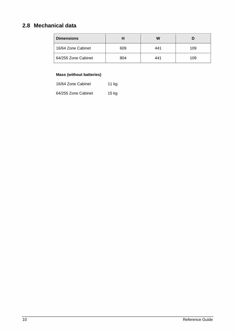
2.8 Mechanical data
Dimensions H W D
16/64 Zone Cabinet 609 441 109
64/255 Zone Cabinet 804 441 109
Mass (without batteries)
16/64 Zone Cabinet 11 kg
64/255 Zone Cabinet 15 kg
Reference Guide 11
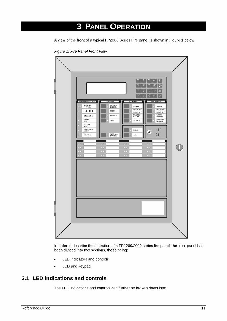
3 PANEL OPERATION A view of the front of a typical FP2000 Series Fire panel is shown in Figure 1 below.
Figure 1: Fire Panel Front View
In order to describe the operation of a FP1200/2000 series fire panel, the front panel has been divided into two sections, these being:
• LED indicators and controls
• LCD and keypad
3.1 LED indications and controls
The LED Indications and controls can further be broken down into:
12 Reference Guide
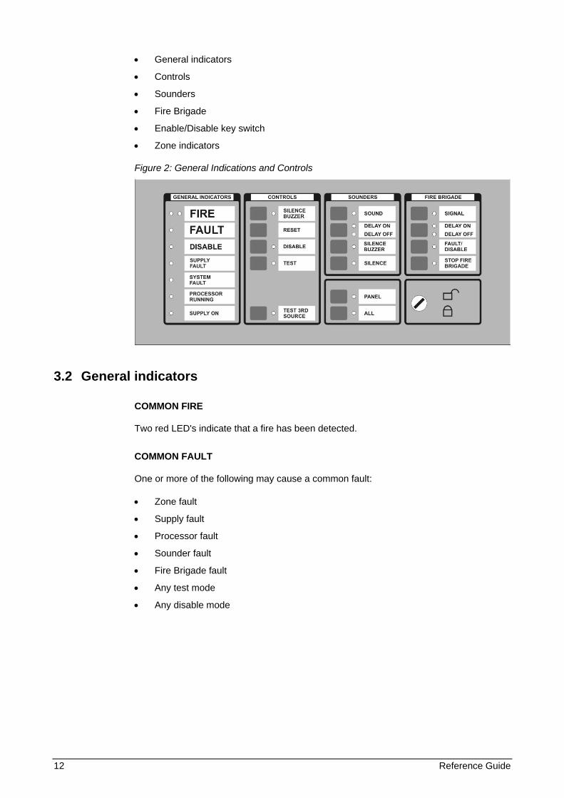
• General indicators
• Controls
• Sounders
• Fire Brigade
• Enable/Disable key switch
• Zone indicators
Figure 2: General Indications and Controls
3.2 General indicators
COMMON FIRE
Two red LED's indicate that a fire has been detected.
COMMON FAULT
One or more of the following may cause a common fault:
• Zone fault
• Supply fault
• Processor fault
• Sounder fault
• Fire Brigade fault
• Any test mode
• Any disable mode
Reference Guide 13
COMMON DISABLE
A yellow LED indicates that one or more of the following have been disabled:
• Devices on the loop
• Zone
• Sounders
• Fire Brigade
SUPPLY FAULT
A yellow LED will illuminate for:
• Mains failure
• Battery disconnect or not charging
SYSTEM FAULT
A yellow LED indicates that a system fault has occurred. A system failure can be one or more of the following:
• Tamper switch
• Service switch
• Logic error
• Memory lock
• No checksums calculated
• Hardware test fault
• Fireman’s panel down
• Repeater down
• Panel down
• Global repeater down
• Input fault
• Output fault
• Configuration fault
• Checksum fault
• Protected memory overwritten
• Time date wrong
• Access fault
• FEP fault
• Watchdog time-out
PROCESSOR RUNNING
A flashing green LED indicates normal operation.
SUPPLY ON
A green LED indicates that the system is receiving 24V power.
14 Reference Guide
3.3 Controls
SILENCE BUZZER (Key switch Enabled or Disabled)
The internal panel buzzer is activated for any new condition. The buzzer is ON continuously for a fire alarm condition, intermittent for a fault warning and slow intermittent for a condition warning.
Pressing the Silence Buzzer key silences the buzzer. The yellow silence buzzer LED will illuminate to indicate that the buzzer has been silenced.
RESET (Key switch Enabled)
This pushbutton will reset the fire panel.
DISABLE (Key switch Enabled)
This pushbutton calls up the Disable Menu (see Page 212). The yellow LED will indicate if anything is disabled.
TEST (Key switch Enabled)
This pushbutton calls up the Test Menu (see Page 199). The yellow LED under General Indicators will illuminate if the panel is put into a test mode.
3.4 Sounders
SOUND
The functionality depends on the operation mode selected by bits 5 and 6 of the DIP switch on the HOST Power Supply board on the FP2000 (see the FP1200/2000 Installation and Commissioning Manual) or the mode of operation selected in the System Setup screen for the FP1200. (Refer to page 65.)
A red LED indicates that the sounders have been activated.
DELAY ON/OFF
The programmed Sounder Delay (see Output Delays, Page 81) may be toggled ON or OFF. Two LEDs indicate the state.
FAULT/DISABLE (Key switch Enabled)
The Sounder Fault/Disable pushbutton allows the sounders to be disabled. The associated LED indicates that the sounders have been disabled (LED on) or that a sounder fault is present (LED blinking).
A sounder fault can be:
• Sounder circuit open circuit
• Sounder circuit short circuit
Reference Guide 15
SILENCE (Key switch Enabled)
A yellow LED indicates that the sounders have been silenced.
3.5 Fire brigade
SIGNAL (Key switch Enabled)
A red LED will indicate that the signal has been activated.
DELAY ON/OFF
The programmed Fire Brigade Signal Delay (see Output Delays, Page 81) may be toggled ON or OFF. Two LEDs indicate the state.
FAULT/DISABLE (Key switch Enabled)
The fire brigade output may be disabled using this pushbutton. When the signal is disabled, then the disable LED is illuminated.
The Fire Brigade circuit is supervised. The Fire Brigade fault LED will flash when a fault is detected in the circuit.
STOP FIRE BRIGADE (Key switch Enabled)
A yellow LED will indicate that the Fire Brigade signal has been deactivated.
ENABLE/DISABLE KEY SWITCH
An Enable/Disable key switch is provided to either allow or prevent operation of the fire panel controls. The Silence Buzzer, Test and Delay OFF keys will operate with the key switch in any position.
Level 1 for Disable and level 2 for Enable must not be confused with access levels 1 and 2. There is no relation between the Enable/Disable key switch and the allocated access levels.
3.6 Other
PANEL
This button is used by global and local repeaters for panel emulation. Emulation mode is activated with a global repeater by pressing the ‘Panel‘ key, then entering the number of
the panel to be emulated, and Enter ( ).
To stop emulation, the Panel key is pressed and then "0" and Enter ( ).
When a global repeater is emulating a panel, it is not necessary to stop emulation before emulating another panel. The global repeater will automatically stop the emulation before trying to emulate another panel.
With a local repeater, pressing the Panel key will start emulation of the panel. If the panel is already emulated, pressing the Panel key will stop emulation.
16 Reference Guide
The yellow LED indicates whether a panel is emulated or not.
ALL
This is used by a Global Repeater to send a command to all the panels this global repeater is communicating with. The yellow LED indicates that the key was pressed, meaning that the following command button to be pressed is sent to all the relevant panels.
THIRD SOURCE TEST
This key tests the third source battery when the panel is powered. Pressing the key will sound the buzzer.
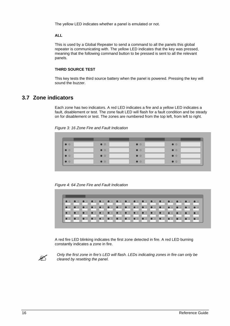
3.7 Zone indicators
Each zone has two indicators. A red LED indicates a fire and a yellow LED indicates a fault, disablement or test. The zone fault LED will flash for a fault condition and be steady on for disablement or test. The zones are numbered from the top left, from left to right.
Figure 3: 16 Zone Fire and Fault Indication
Figure 4: 64 Zone Fire and Fault Indication
A red fire LED blinking indicates the first zone detected in fire. A red LED burning constantly indicates a zone in fire.
Only the first zone in fire’s LED will flash. LEDs indicating zones in fire can only be cleared by resetting the panel.
Reference Guide 17
3.8 LCD and keypad
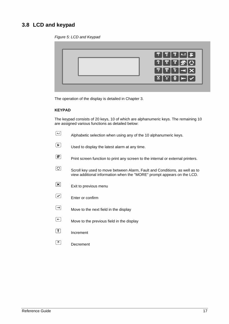
Figure 5: LCD and Keypad
The operation of the display is detailed in Chapter 3.
KEYPAD
The keypad consists of 20 keys, 10 of which are alphanumeric keys. The remaining 10 are assigned various functions as detailed below:
Alphabetic selection when using any of the 10 alphanumeric keys.
Used to display the latest alarm at any time.
Print screen function to print any screen to the internal or external printers.
Scroll key used to move between Alarm, Fault and Conditions, as well as to view additional information when the "MORE" prompt appears on the LCD.
Exit to previous menu
Enter or confirm
Move to the next field in the display
Move to the previous field in the display
Increment
Decrement
18 Reference Guide
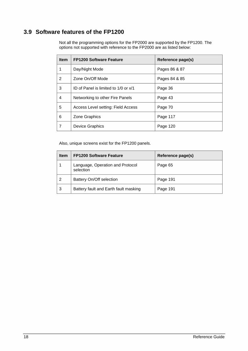
3.9 Software features of the FP1200
Not all the programming options for the FP2000 are supported by the FP1200. The options not supported with reference to the FP2000 are as listed below:
Item FP1200 Software Feature Reference page(s)
1 Day/Night Mode Pages 86 & 87
2 Zone On/Off Mode Pages 84 & 85
3 ID of Panel is limited to 1/0 or x/1 Page 36
4 Networking to other Fire Panels Page 43
5 Access Level setting: Field Access Page 70
6 Zone Graphics Page 117
7 Device Graphics Page 120
Also, unique screens exist for the FP1200 panels.
Item FP1200 Software Feature Reference page(s)
1 Language, Operation and Protocol selection
Page 65
2 Battery On/Off selection Page 191
3 Battery fault and Earth fault masking Page 191
Reference Guide 19
4 LCD SCREEN OPERATION
4.1 Start-up screens
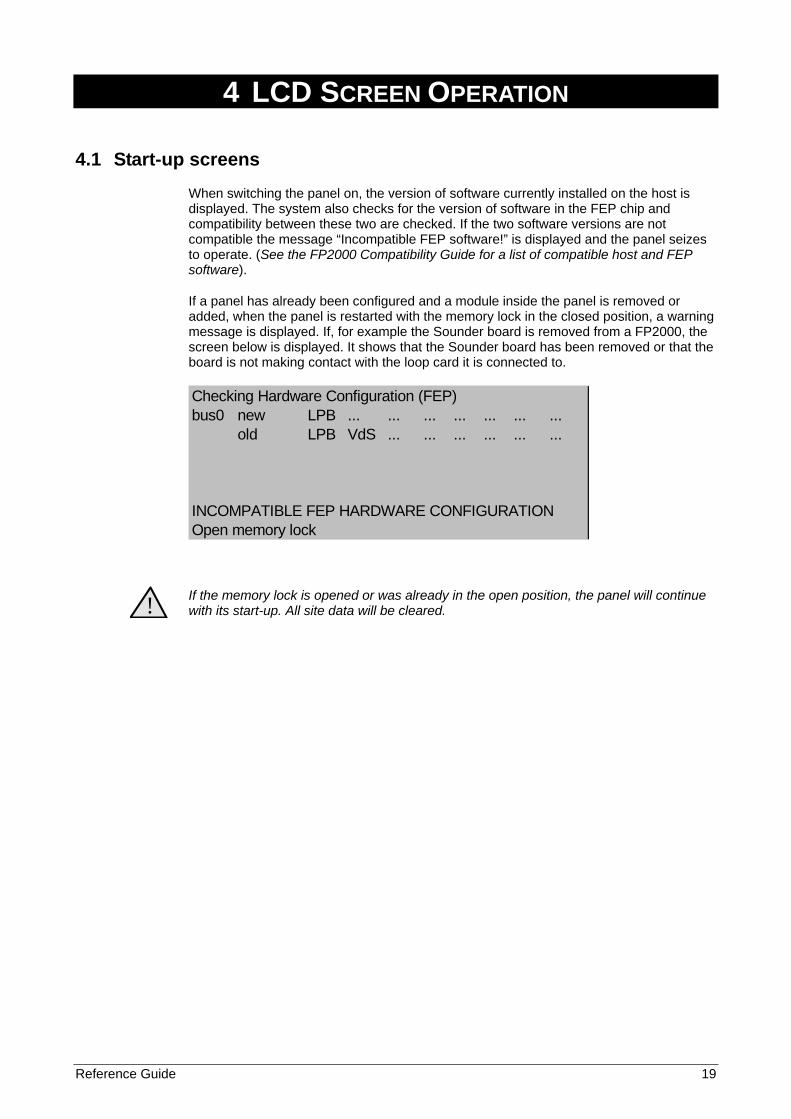
When switching the panel on, the version of software currently installed on the host is displayed. The system also checks for the version of software in the FEP chip and compatibility between these two are checked. If the two software versions are not compatible the message “Incompatible FEP software!” is displayed and the panel seizes to operate. (See the FP2000 Compatibility Guide for a list of compatible host and FEP software).
If a panel has already been configured and a module inside the panel is removed or added, when the panel is restarted with the memory lock in the closed position, a warning message is displayed. If, for example the Sounder board is removed from a FP2000, the screen below is displayed. It shows that the Sounder board has been removed or that the board is not making contact with the loop card it is connected to.
Checking Hardware Configuration (FEP)bus0 new LPB ... ... ... ... ... ... ...
old LPB VdS ... ... ... ... ... ...
INCOMPATIBLE FEP HARDWARE CONFIGURATIONOpen memory lock
!
If the memory lock is opened or was already in the open position, the panel will continue with its start-up. All site data will be cleared.
20 Reference Guide
4.2 Alarm line
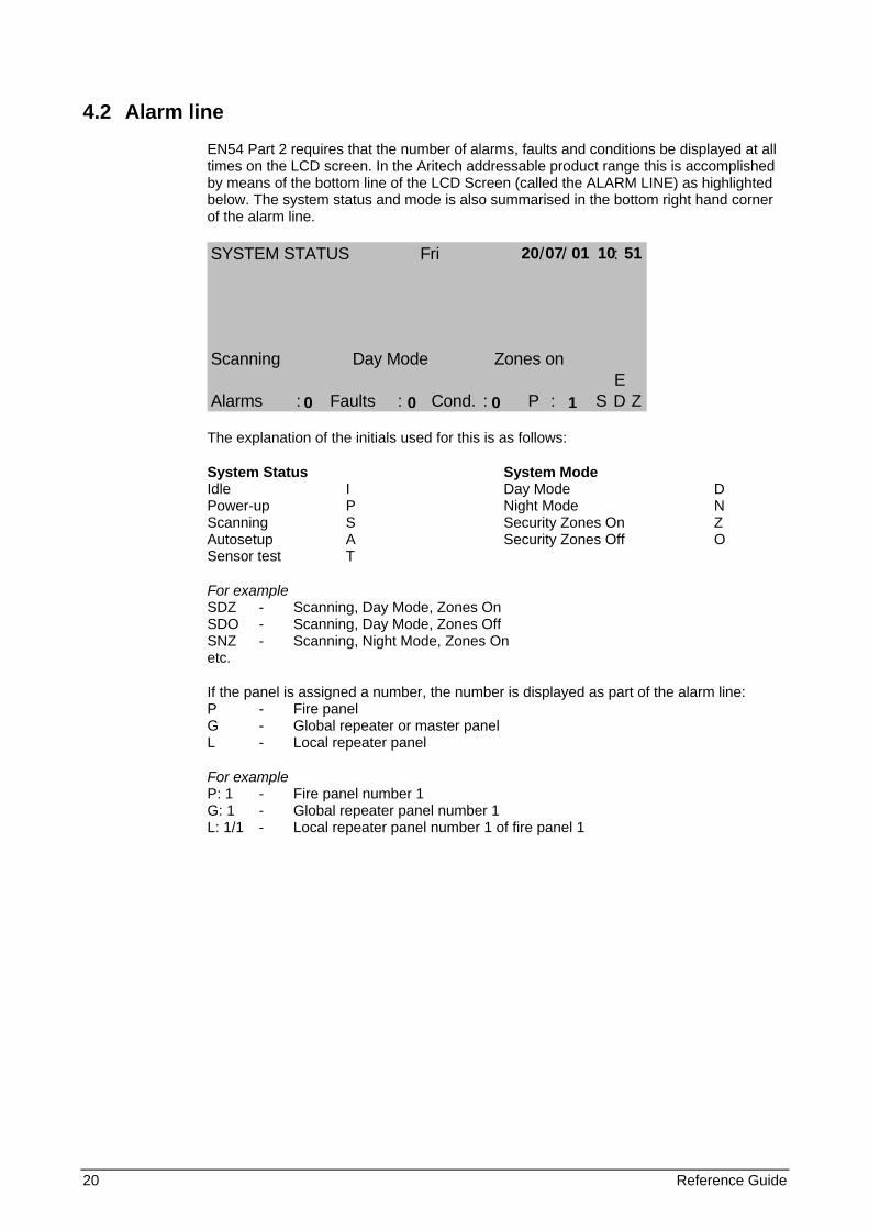
EN54 Part 2 requires that the number of alarms, faults and conditions be displayed at all times on the LCD screen. In the Aritech addressable product range this is accomplished by means of the bottom line of the LCD Screen (called the ALARM LINE) as highlighted below. The system status and mode is also summarised in the bottom right hand corner of the alarm line.
SYSTEM STATUS Fri / / :
Scanning Day Mode Zones onE
Alarms : Faults : Cond. : P : S D Z
The explanation of the initials used for this is as follows:
System Status System Mode Idle I Day Mode D Power-up P Night Mode N Scanning S Security Zones On Z Autosetup A Security Zones Off O Sensor test T
For example SDZ - Scanning, Day Mode, Zones On SDO - Scanning, Day Mode, Zones Off SNZ - Scanning, Night Mode, Zones On etc.
If the panel is assigned a number, the number is displayed as part of the alarm line: P - Fire panel G - Global repeater or master panel L - Local repeater panel
For example P: 1 - Fire panel number 1 G: 1 - Global repeater panel number 1 L: 1/1 - Local repeater panel number 1 of fire panel 1
20 07 01 10 51
0 0 0 1
Reference Guide 21
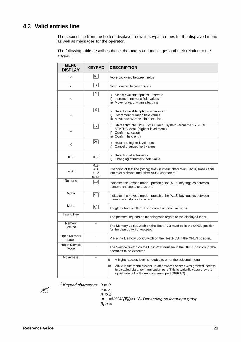
4.3 Valid entries line
The second line from the bottom displays the valid keypad entries for the displayed menu, as well as messages for the operator.
The following table describes these characters and messages and their relation to the keypad:
MENU DISPLAY KEYPAD DESCRIPTION
< Move backward between fields
> Move forward between fields
∧ I) Select available options – forward
ii) Increment numeric field values iii) Move forward within a text line
∨ I) Select available options – backward
ii) Decrement numeric field values iii) Move backward within a text line
E i) Start entry into FP1200/2000 menu system - from the SYSTEM
STATUS Menu (highest level menu) ii) Confirm selection iii) Confirm field entry
X I) Return to higher level menu ii) Cancel changed field values
0..9 0..9 I) Selection of sub-menus ii) Changing of numeric field value
A..z
0..9 a..z A...Z
other1
Changing of test line (string) text - numeric characters 0 to 9, small capital letters of alphabet and other ASCII characters1.
Numeric Indicates the keypad mode - pressing the [A...Z] key toggles between
numeric and alpha characters.
Alpha Indicates the keypad mode - pressing the [A...Z] key toggles between
numeric and alpha characters.
More Toggle between different screens of a particular menu.
Invalid Key - The pressed key has no meaning with regard to the displayed menu.
Memory Locked
- The Memory Lock Switch on the Host PCB must be in the OPEN position for the change to be accepted.
Open Memory Lock
- Place the Memory Lock Switch on the Host PCB in the OPEN position.
Not in Service Mode
- The Service Switch on the Host PCB must be in the OPEN position for the operation to be executed.
No Access - I) A higher access level is needed to enter the selected menu
II) While in the menu system, in other words access was granted, access is disabled via a communication port. This is typically caused by the up-/download software via a serial port (SER1/2).
1 Keypad characters: 0 to 9 a to z A to Z .=*,~#$%^&`{}[]()<>:"/ - Depending on language group Space
22 Reference Guide
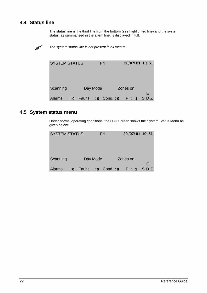
4.4 Status line
The status line is the third line from the bottom (see highlighted line) and the system status, as summarised in the alarm line, is displayed in full.
The system status line is not present in all menus:
SYSTEM STATUS Fri / / :
Scanning Day Mode Zones onE
Alarms : Faults : Cond. : P : S D Z
4.5 System status menu
Under normal operating conditions, the LCD Screen shows the System Status Menu as given below:
SYSTEM STATUS Fri / / :
Scanning Day Mode Zones onE
Alarms : Faults : Cond. : P : S D Z
20 07 01 10 51
0 0 0 1
20 07 01 10 51
0 0 0 1
Reference Guide 23
5 PROGRAMMING MENUS
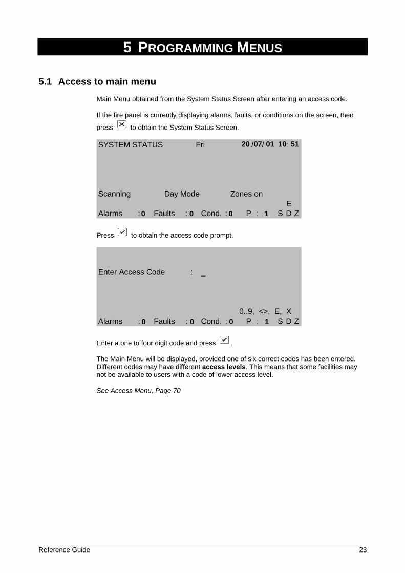
5.1 Access to main menu
Main Menu obtained from the System Status Screen after entering an access code.
If the fire panel is currently displaying alarms, faults, or conditions on the screen, then
press to obtain the System Status Screen.
SYSTEM STATUS Fri / / :
Scanning Day Mode Zones onE
Alarms : Faults : Cond. : P : S D Z
Press to obtain the access code prompt.
Enter Access Code : _
0..9, <>, E, XAlarms : Faults : Cond. : P : S D Z
Enter a one to four digit code and press .
The Main Menu will be displayed, provided one of six correct codes has been entered. Different codes may have different access levels. This means that some facilities may not be available to users with a code of lower access level.
See Access Menu, Page 70
20 07 01 10 51
0 0 0 1
0 0 0 1
24 Reference Guide
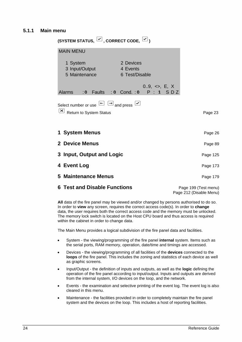
5.1.1 Main menu
(SYSTEM STATUS, , CORRECT CODE, )
MAIN MENU
1 System 2 Devices3 Input/Output 4 Events5 Maintenance 6 Test/Disable
0..9, <>, E, XAlarms : Faults : Cond. : P : S D Z
Select number or use and press
Return to System Status Page 23
1 System Menus Page 26
2 Device Menus Page 89
3 Input, Output and Logic Page 125
4 Event Log Page 173
5 Maintenance Menus Page 179
6 Test and Disable Functions Page 199 (Test menu) Page 212 (Disable Menu)
All data of the fire panel may be viewed and/or changed by persons authorised to do so. In order to view any screen, requires the correct access code(s). In order to change data, the user requires both the correct access code and the memory must be unlocked. The memory lock switch is located on the Host CPU board and thus access is required within the cabinet in order to change data.
The Main Menu provides a logical subdivision of the fire panel data and facilities.
• System - the viewing/programming of the fire panel internal system. Items such as the serial ports, RAM memory, operation, date/time and timings are accessed.
• Devices - the viewing/programming of all facilities of the devices connected to the loops of the fire panel. This includes the zoning and statistics of each device as well as graphic screens.
• Input/Output - the definition of inputs and outputs, as well as the logic defining the operation of the fire panel according to input/output. Inputs and outputs are derived from the internal system, I/O devices on the loop, and the network.
• Events - the examination and selective printing of the event log. The event log is also cleared in this menu.
• Maintenance - the facilities provided in order to completely maintain the fire panel system and the devices on the loop. This includes a host of reporting facilities.
0 0 0 1

Reference Guide 25
• Test/Disable - Zones and individual devices can be selectively tested and disabled. Test features include one-man test of zones and soak test of individual devices. The Test and Disable Menus are not directly available from the Main Menu, but are accessed by using the Test and Disable keys on the front panel. These menus do not require any access code, but do require that the enable/disable key switch be enabled. Selecting Test/Disable from the Main Menu causes a prompt to operate the desired key switch.
26 Reference Guide
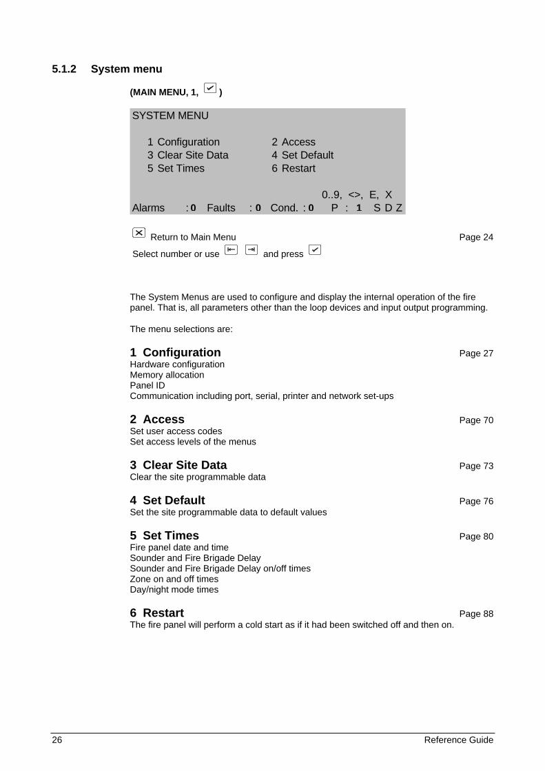
5.1.2 System menu
(MAIN MENU, 1, )
SYSTEM MENU
1 Configuration 2 Access3 Clear Site Data 4 Set Default5 Set Times 6 Restart
0..9, <>, E, XAlarms : Faults : Cond. : P : S D Z
Return to Main Menu Page 24
Select number or use and press
The System Menus are used to configure and display the internal operation of the fire panel. That is, all parameters other than the loop devices and input output programming.
The menu selections are:
1 Configuration Page 27 Hardware configuration Memory allocation Panel ID Communication including port, serial, printer and network set-ups
2 Access Page 70 Set user access codes Set access levels of the menus
3 Clear Site Data Page 73 Clear the site programmable data
4 Set Default Page 76 Set the site programmable data to default values
5 Set Times Page 80 Fire panel date and time Sounder and Fire Brigade Delay Sounder and Fire Brigade Delay on/off times Zone on and off times Day/night mode times
6 Restart Page 88 The fire panel will perform a cold start as if it had been switched off and then on.
0 0 0 1
Reference Guide 27
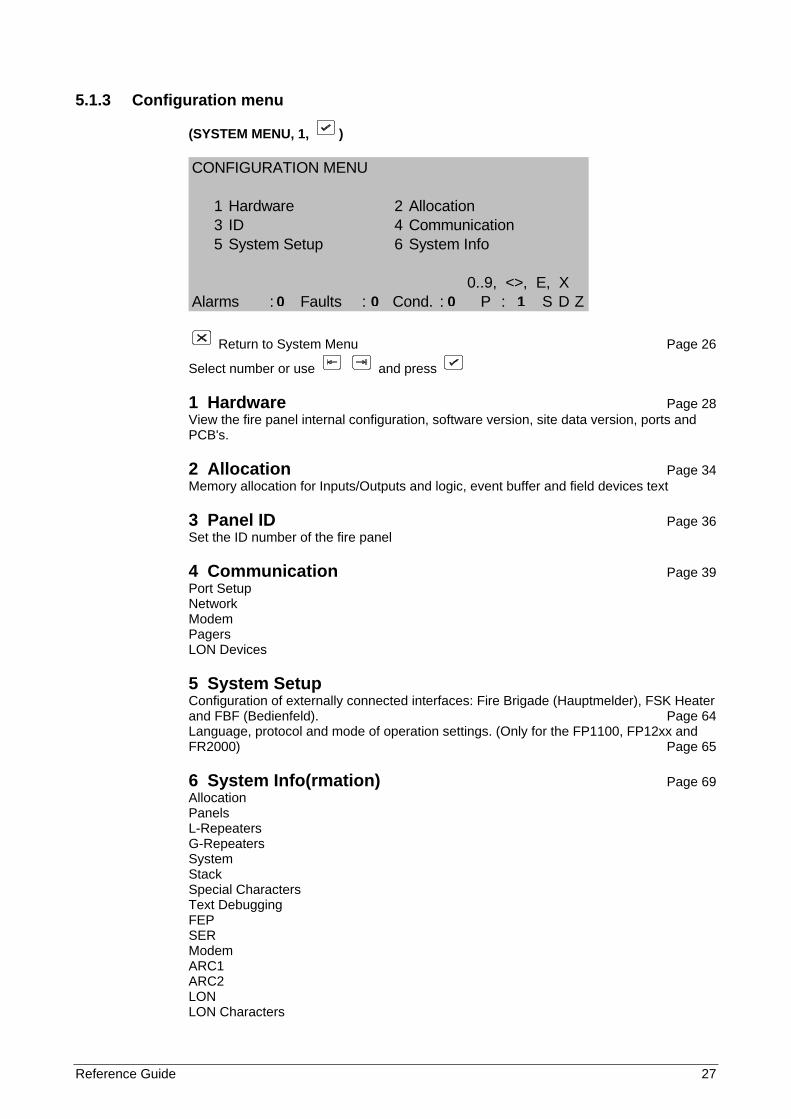
5.1.3 Configuration menu
(SYSTEM MENU, 1, )
CONFIGURATION MENU
1 Hardware 2 Allocation3 ID 4 Communication5 System Setup 6 System Info
0..9, <>, E, XAlarms : Faults : Cond. : P : S D Z
Return to System Menu Page 26
Select number or use and press
1 Hardware Page 28 View the fire panel internal configuration, software version, site data version, ports and PCB's.
2 Allocation Page 34 Memory allocation for Inputs/Outputs and logic, event buffer and field devices text
3 Panel ID Page 36 Set the ID number of the fire panel
4 Communication Page 39 Port Setup Network Modem Pagers LON Devices
5 System Setup Configuration of externally connected interfaces: Fire Brigade (Hauptmelder), FSK Heater and FBF (Bedienfeld). Page 64 Language, protocol and mode of operation settings. (Only for the FP1100, FP12xx and FR2000) Page 65
6 System Info(rmation) Page 69 Allocation Panels L-Repeaters G-Repeaters System Stack Special Characters Text Debugging FEP SER Modem ARC1 ARC2 LON LON Characters
0 0 0 1
28 Reference Guide
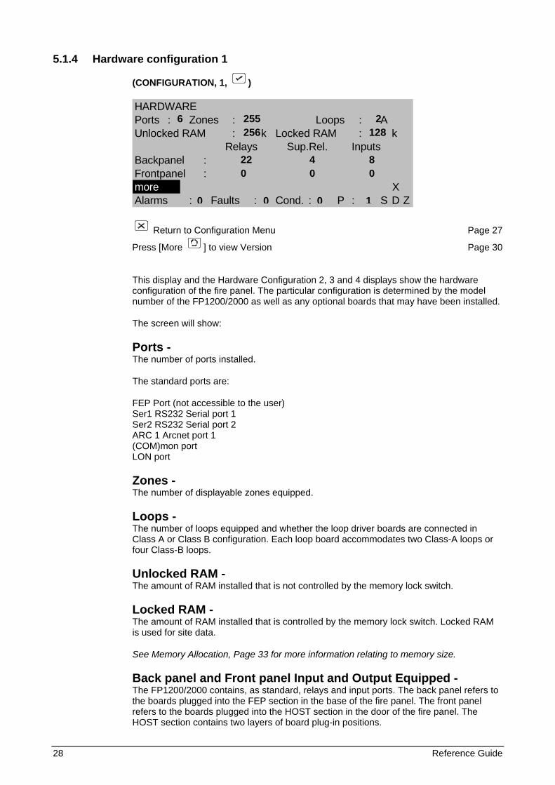
5.1.4 Hardware configuration 1
(CONFIGURATION, 1, )
HARDWAREPorts : Zones : Loops : AUnlocked RAM : k Locked RAM : k
Relays Sup.Rel. InputsBackpanel :Frontpanel :more XAlarms : Faults : Cond. : P : S D Z
Return to Configuration Menu Page 27
Press [More ] to view Version Page 30
This display and the Hardware Configuration 2, 3 and 4 displays show the hardware configuration of the fire panel. The particular configuration is determined by the model number of the FP1200/2000 as well as any optional boards that may have been installed.
The screen will show:
Ports - The number of ports installed.
The standard ports are:
FEP Port (not accessible to the user) Ser1 RS232 Serial port 1 Ser2 RS232 Serial port 2 ARC 1 Arcnet port 1 (COM)mon port LON port
Zones - The number of displayable zones equipped.
Loops - The number of loops equipped and whether the loop driver boards are connected in Class A or Class B configuration. Each loop board accommodates two Class-A loops or four Class-B loops.
Unlocked RAM - The amount of RAM installed that is not controlled by the memory lock switch.
Locked RAM - The amount of RAM installed that is controlled by the memory lock switch. Locked RAM is used for site data.
See Memory Allocation, Page 33 for more information relating to memory size.
Back panel and Front panel Input and Output Equipped - The FP1200/2000 contains, as standard, relays and input ports. The back panel refers to the boards plugged into the FEP section in the base of the fire panel. The front panel refers to the boards plugged into the HOST section in the door of the fire panel. The HOST section contains two layers of board plug-in positions.
6 255 2 256 128 22 4 8 0 0 0
0 0 0 1

Reference Guide 29
The standard equipped I/O is:
• Four Inputs IN1 - IN4 located on the FEP board. These inputs are freely programmable by the user.
• Sounder board:
- Four supervised relays (OUT1 - OUT4) - Four non-supervised relays (OUT5 - OUT8)
The supervised relays have dedicated functions:
OUT1 - Sounder OUT2 - Fire Brigade OUT3 - Fire Protection OUT4 - Fault Routing
- Four supervised, general programmable inputs (IN5 - IN8)
All non-supervised relays are programmable by means of the I/O programming menus.
Any additional optional I/O that is equipped within the FP1200/2000 will be shown on this screen.
See I/O Menus, Page 125 for the programming of Inputs and Outputs.
30 Reference Guide
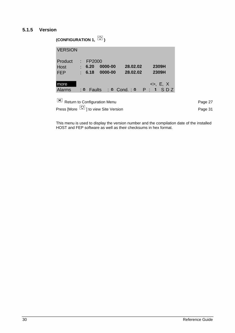
5.1.5 Version
(CONFIGURATION 1, )
VERSION
Product : FP2000Host :FEP :
more <>, E, XAlarms : Faults : Cond. : P : S D Z
Return to Configuration Menu Page 27
Press [More ] to view Site Version Page 31
This menu is used to display the version number and the compilation date of the installed HOST and FEP software as well as their checksums in hex format.
6.20 0000-00 28.02.02 2309H 6.18 0000-00 28.02.02 2309H
0 0 0 1
Reference Guide 31
5.1.6 Site Version
(CONFIGURATION 1, , )
SITE VERSION
Vers. Date Time CheckSite :Block :
more 0..9, ^v, <>, E, XAlarms : Faults : Cond. : P : S D Z
Return to Configuration Menu Page 27
Press [More ] to view Hardware Configuration 2 Page 32
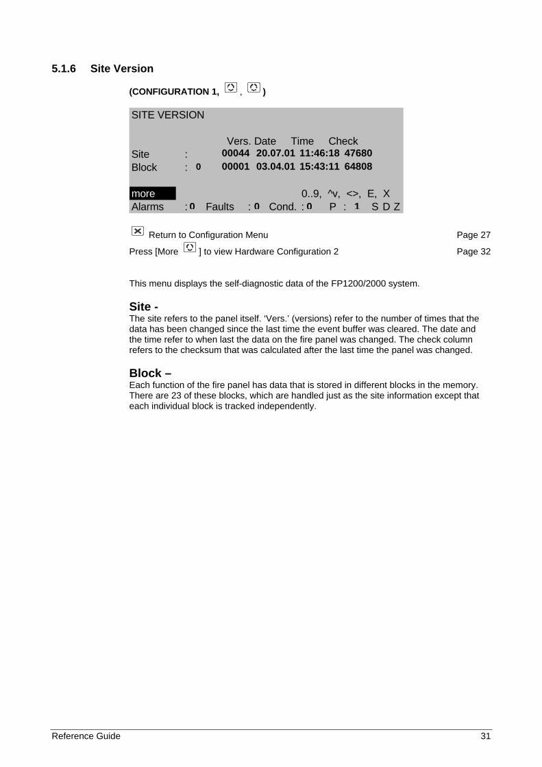
This menu displays the self-diagnostic data of the FP1200/2000 system.
Site - The site refers to the panel itself. ‘Vers.’ (versions) refer to the number of times that the data has been changed since the last time the event buffer was cleared. The date and the time refer to when last the data on the fire panel was changed. The check column refers to the checksum that was calculated after the last time the panel was changed.
Block – Each function of the fire panel has data that is stored in different blocks in the memory. There are 23 of these blocks, which are handled just as the site information except that each individual block is tracked independently.
00044 20.07.01 11:46:18 47680 0 00001 03.04.01 15:43:11 64808
0 0 0 1
32 Reference Guide
5.1.7 Hardware configuration 2
(CONFIGURATION 1, , , )
HARDWARE CONFIGURATION
Host : DEN ZON ZON ZON ZON LED: PSH ARC CH2 … … … …
FEP : LPA LPA LPA REL VdS FSKADD : FEP HST KBD LCD PSF … …more <>, E, XAlarms : Faults : Cond. : P : S D Z
Return to Configuration Menu Page 27
Select the PC Board code using the cursor
View additional details of the selected PC Board
Press [More ] to view Hardware Configuration 1 Page 28
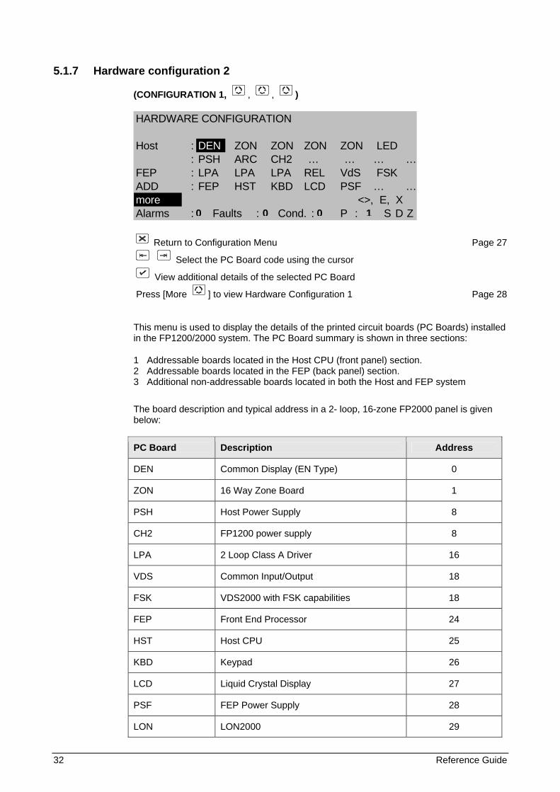
This menu is used to display the details of the printed circuit boards (PC Boards) installed in the FP1200/2000 system. The PC Board summary is shown in three sections:
1 Addressable boards located in the Host CPU (front panel) section. 2 Addressable boards located in the FEP (back panel) section. 3 Additional non-addressable boards located in both the Host and FEP system
The board description and typical address in a 2- loop, 16-zone FP2000 panel is given below:
PC Board Description Address
DEN Common Display (EN Type) 0
ZON 16 Way Zone Board 1
PSH Host Power Supply 8
CH2 FP1200 power supply 8
LPA 2 Loop Class A Driver 16
VDS Common Input/Output 18
FSK VDS2000 with FSK capabilities 18
FEP Front End Processor 24
HST Host CPU 25
KBD Keypad 26
LCD Liquid Crystal Display 27
PSF FEP Power Supply 28
LON LON2000 29
0 0 0 1
Reference Guide 33
5.1.8 Board information
(HARDWARE CONFIGURATION 2, or, , )
BOARD INFORMATION
Addr. : Sup1 : passive Inp5 : shortID : Sup2 : active Inp6 : openType : VdS Sup3 : open Inp7 : active
Sup4 : short Inp8 : passiveX
Alarms : Faults : Cond. : P : S D Z
Return to Hardware Configuration 2 Page 32
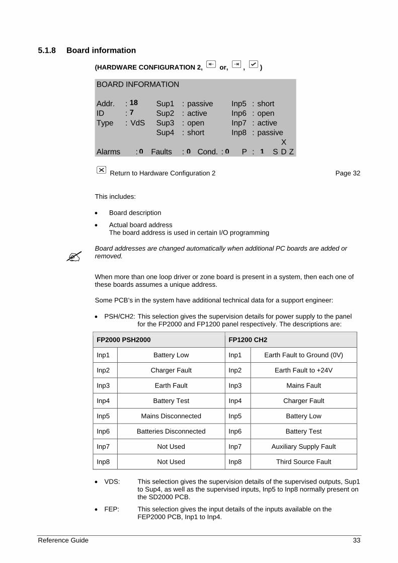
This includes:
• Board description
• Actual board address The board address is used in certain I/O programming
Board addresses are changed automatically when additional PC boards are added or removed.
When more than one loop driver or zone board is present in a system, then each one of these boards assumes a unique address.
Some PCB’s in the system have additional technical data for a support engineer:
• PSH/CH2: This selection gives the supervision details for power supply to the panel for the FP2000 and FP1200 panel respectively. The descriptions are:
FP2000 PSH2000 FP1200 CH2
Inp1 Battery Low Inp1 Earth Fault to Ground (0V)
Inp2 Charger Fault Inp2 Earth Fault to +24V
Inp3 Earth Fault Inp3 Mains Fault
Inp4 Battery Test Inp4 Charger Fault
Inp5 Mains Disconnected Inp5 Battery Low
Inp6 Batteries Disconnected Inp6 Battery Test
Inp7 Not Used Inp7 Auxiliary Supply Fault
Inp8 Not Used Inp8 Third Source Fault
• VDS: This selection gives the supervision details of the supervised outputs, Sup1
to Sup4, as well as the supervised inputs, Inp5 to Inp8 normally present on the SD2000 PCB.
• FEP: This selection gives the input details of the inputs available on the FEP2000 PCB, Inp1 to Inp4.
18 7
0 0 0 1
34 Reference Guide
5.1.9 Memory allocation 1
(CONFIGURATION, 2, )
MEMORY ALLOCATION Free unlocked :Free locked :
Logic : Input Text :Inputs : Output Text :Outputs : Zone Text :Events : Area Text :more 0..9, ^v, <>, E, XAlarms : Faults : Cond. : P : S D Z
Return to Configuration Menu Page 27
Select item to be changed
or 0..9 change data in item (Unlock memory!)
Confirm change
Press [More ] to view Memory Allocation 2 Page 35
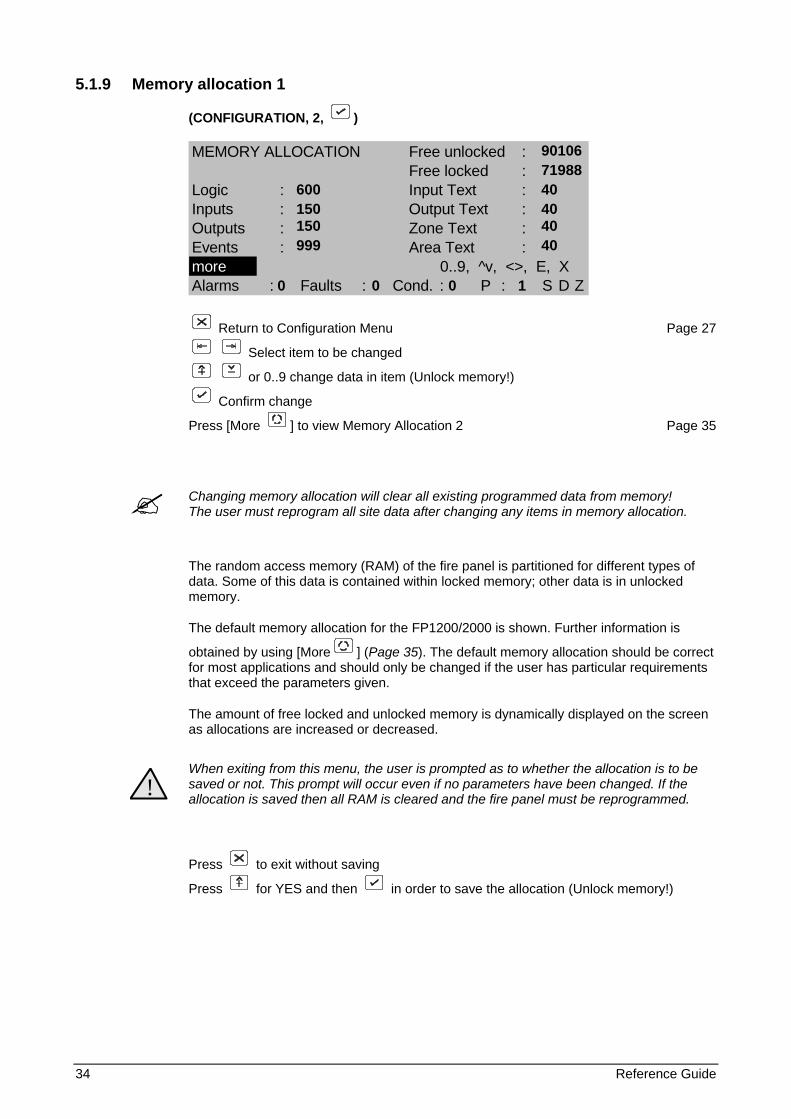
Changing memory allocation will clear all existing programmed data from memory! The user must reprogram all site data after changing any items in memory allocation.
The random access memory (RAM) of the fire panel is partitioned for different types of data. Some of this data is contained within locked memory; other data is in unlocked memory.
The default memory allocation for the FP1200/2000 is shown. Further information is
obtained by using [More ] (Page 35). The default memory allocation should be correct for most applications and should only be changed if the user has particular requirements that exceed the parameters given.
The amount of free locked and unlocked memory is dynamically displayed on the screen as allocations are increased or decreased.
!
When exiting from this menu, the user is prompted as to whether the allocation is to be saved or not. This prompt will occur even if no parameters have been changed. If the allocation is saved then all RAM is cleared and the fire panel must be reprogrammed.
Press to exit without saving
Press for YES and then in order to save the allocation (Unlock memory!)
90106 71988 600 40 150 40 150 40 999 40 0 0 0 1
Reference Guide 35
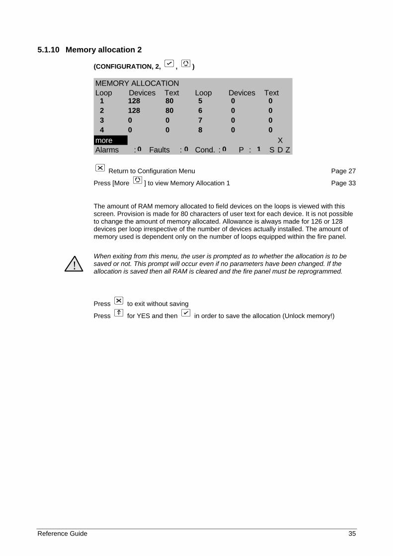
5.1.10 Memory allocation 2
(CONFIGURATION, 2, , )
MEMORY ALLOCATIONLoop Devices Text Loop Devices Text
more XAlarms : Faults : Cond. : P : S D Z
Return to Configuration Menu Page 27
Press [More ] to view Memory Allocation 1 Page 33
The amount of RAM memory allocated to field devices on the loops is viewed with this screen. Provision is made for 80 characters of user text for each device. It is not possible to change the amount of memory allocated. Allowance is always made for 126 or 128 devices per loop irrespective of the number of devices actually installed. The amount of memory used is dependent only on the number of loops equipped within the fire panel.
!
When exiting from this menu, the user is prompted as to whether the allocation is to be saved or not. This prompt will occur even if no parameters have been changed. If the allocation is saved then all RAM is cleared and the fire panel must be reprogrammed.
Press to exit without saving
Press for YES and then in order to save the allocation (Unlock memory!)
1 128 80 5 0 0 2 128 80 6 0 0 3 0 0 7 0 0 4 0 0 8 0 0
0 0 0 1
36 Reference Guide
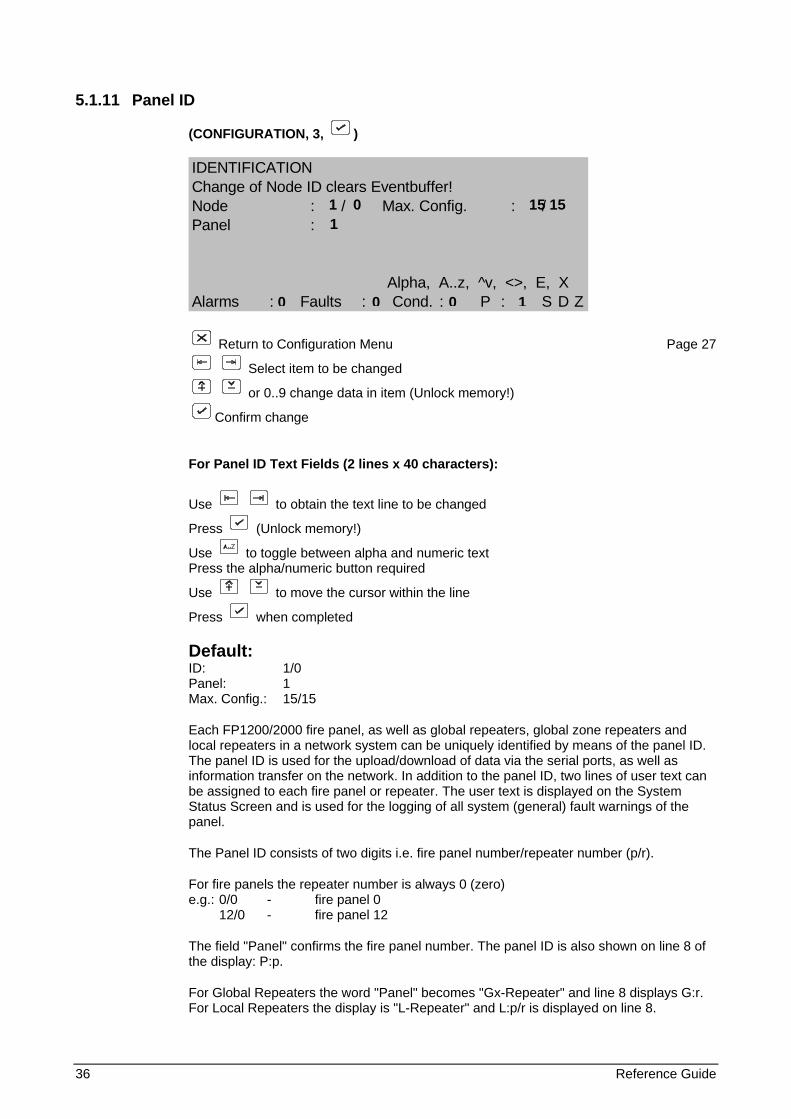
5.1.11 Panel ID
(CONFIGURATION, 3, )
IDENTIFICATIONChange of Node ID clears Eventbuffer!Node : / Max. Config. : /Panel :
Alpha, A..z, ^v, <>, E, XAlarms : Faults : Cond. : P : S D Z
Return to Configuration Menu Page 27
Select item to be changed
or 0..9 change data in item (Unlock memory!)
Confirm change
For Panel ID Text Fields (2 lines x 40 characters):
Use to obtain the text line to be changed
Press (Unlock memory!)
Use to toggle between alpha and numeric text Press the alpha/numeric button required
Use to move the cursor within the line
Press when completed
Default: ID: 1/0 Panel: 1 Max. Config.: 15/15
Each FP1200/2000 fire panel, as well as global repeaters, global zone repeaters and local repeaters in a network system can be uniquely identified by means of the panel ID. The panel ID is used for the upload/download of data via the serial ports, as well as information transfer on the network. In addition to the panel ID, two lines of user text can be assigned to each fire panel or repeater. The user text is displayed on the System Status Screen and is used for the logging of all system (general) fault warnings of the panel.
The Panel ID consists of two digits i.e. fire panel number/repeater number (p/r).
For fire panels the repeater number is always 0 (zero) e.g.: 0/0 - fire panel 0 12/0 - fire panel 12
The field "Panel" confirms the fire panel number. The panel ID is also shown on line 8 of the display: P:p.
For Global Repeaters the word "Panel" becomes "Gx-Repeater" and line 8 displays G:r. For Local Repeaters the display is "L-Repeater" and L:p/r is displayed on line 8.
1 0 15 15 1
0 0 0 1
Reference Guide 37
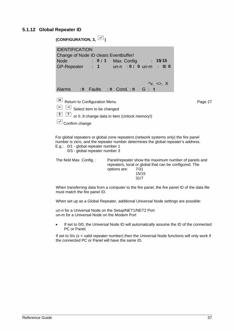
5.1.12 Global Repeater ID
(CONFIGURATION, 3, )
IDENTIFICATIONChange of Node ID clears Eventbuffer!Node : / Max. Config. : /GP-Repeater : un-n : / un-m : /
^v, <>, XAlarms : Faults : Cond. : G :
Return to Configuration Menu Page 27
Select item to be changed
or 0..9 change data in item (Unlock memory!)
Confirm change
For global repeaters or global zone repeaters (network systems only) the fire panel number is zero, and the repeater number determines the global repeater’s address. E.g.: 0/1 - global repeater number 1
0/3 - global repeater number 3
The field Max. Config. : Panel/repeater show the maximum number of panels and repeaters, local or global that can be configured. The options are: 7/31 15/15 31/7
When transferring data from a computer to the fire panel, the fire panel ID of the data file must match the fire panel ID.
When set up as a Global Repeater, additional Universal Node settings are possible:
un-n for a Universal Node on the Setup/NET1/NET2 Port un-m for a Universal Node on the Modem Port
• If set to 0/0, the Universal Node ID will automatically assume the ID of the connected PC or Panel.
If set to 0/x (x = valid repeater number) then the Universal Node functions will only work if the connected PC or Panel will have the same ID.
0 1 15 15 1 0 0 0 0
0 0 0 1
38 Reference Guide
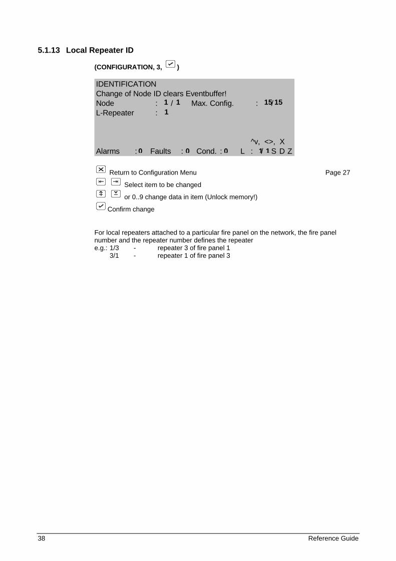
5.1.13 Local Repeater ID
(CONFIGURATION, 3, )
IDENTIFICATIONChange of Node ID clears Eventbuffer!Node : / Max. Config. : /L-Repeater :
^v, <>, XAlarms : Faults : Cond. : L : / S D Z
Return to Configuration Menu Page 27
Select item to be changed
or 0..9 change data in item (Unlock memory!)
Confirm change
For local repeaters attached to a particular fire panel on the network, the fire panel number and the repeater number defines the repeater e.g.: 1/3 - repeater 3 of fire panel 1 3/1 - repeater 1 of fire panel 3
1 1 15 15 1
0 0 0 1 1
Reference Guide 39
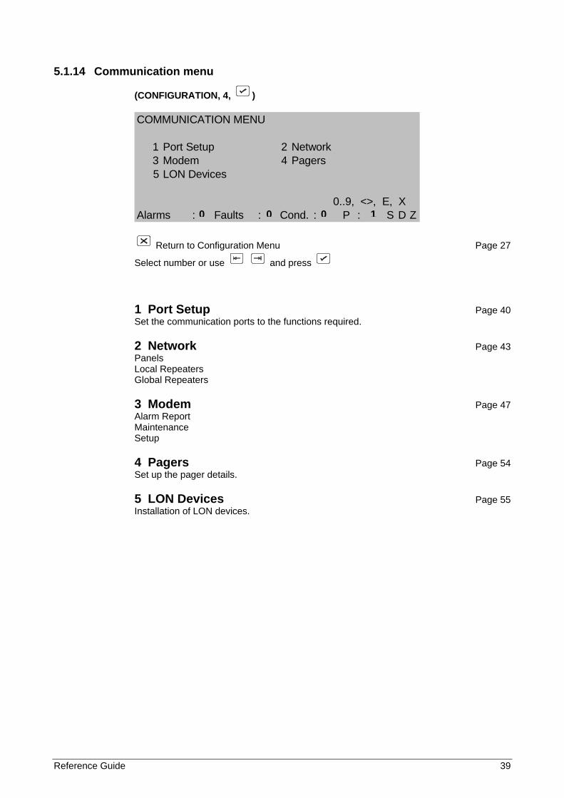
5.1.14 Communication menu
(CONFIGURATION, 4, )
COMMUNICATION MENU
1 Port Setup 2 Network3 Modem 4 Pagers5 LON Devices
0..9, <>, E, XAlarms : Faults : Cond. : P : S D Z
Return to Configuration Menu Page 27
Select number or use and press
1 Port Setup Page 40 Set the communication ports to the functions required.
2 Network Page 43 Panels Local Repeaters Global Repeaters
3 Modem Page 47 Alarm Report Maintenance Setup
4 Pagers Page 54 Set up the pager details.
5 LON Devices Page 55 Installation of LON devices.
0 0 0 1
40 Reference Guide
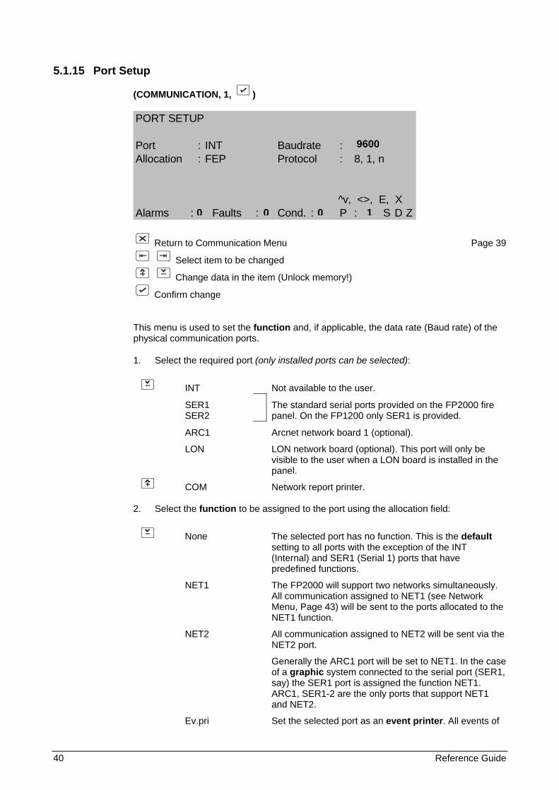
5.1.15 Port Setup
(COMMUNICATION, 1, )
PORT SETUP
Port : INT Baudrate :Allocation : FEP Protocol : 8, 1, n
^v, <>, E, XAlarms : Faults : Cond. : P : S D Z
Return to Communication Menu Page 39
Select item to be changed
Change data in the item (Unlock memory!)
Confirm change
This menu is used to set the function and, if applicable, the data rate (Baud rate) of the physical communication ports.
1. Select the required port (only installed ports can be selected):
INT Not available to the user.
SER1 SER2
The standard serial ports provided on the FP2000 fire panel. On the FP1200 only SER1 is provided.
ARC1 Arcnet network board 1 (optional). LON LON network board (optional). This port will only be
visible to the user when a LON board is installed in the panel.
COM Network report printer.
2. Select the function to be assigned to the port using the allocation field:
None The selected port has no function. This is the default setting to all ports with the exception of the INT (Internal) and SER1 (Serial 1) ports that have predefined functions.
NET1 The FP2000 will support two networks simultaneously. All communication assigned to NET1 (see Network Menu, Page 43) will be sent to the ports allocated to the NET1 function.
NET2 All communication assigned to NET2 will be sent via the NET2 port.
Generally the ARC1 port will be set to NET1. In the case of a graphic system connected to the serial port (SER1, say) the SER1 port is assigned the function NET1. ARC1, SER1-2 are the only ports that support NET1 and NET2.
Ev.pri Set the selected port as an event printer. All events of
9600
0 0 0 1
Reference Guide 41
the fire panel are sent to the port when they occur. Any information that is manually sent to Ev.Pri by the user will also be printed. The fire panel will give a fault if the device connected to the event printer port is not connected or not ready (e.g. paper out).
Rp.Pri Set the selected port as a report printer. The report printer port is used to manually sent report to a device such as a printer or laptop computer. It is primarily used for selected printing of the event buffer, test reports and such. No fault is given if a report printer is off line or not plugged in. Thus, a report printer can be removed at any time. Reports are held in a buffer when the device connected to the port is not on-line. The type of printer (e.g. internal) can be defined.
When the COM port is enabled, only the Rp.Pri can be selected. When selected the node to which the report must be send must be added. This node can be any other panel on the network. E.g. when a node ID of 16/1 is given, the report from the current panel is printed on the internal printer of panel 16’s local repeater. The local repeater will still be able print its own report on the same internal printer.
VDU This function operates in the same manner as Rp.Pri above, except that the report is halted every 20 lines (one VDU screen). Pressing any character on the VDU device will allow the report to be continued for a further 20 lines. This function is particularly useful for viewing reports on the screen of a laptop computer. Only the serial ports support VDU.
EMU The port is set to emulation mode. Only the serial ports support EMU. This allows the fire panel to be operated remotely by means of a computer. The entire fire panel front panel keyboard and display is accessible via the serial port in this mode.
Pager This function assigns one of the serial ports as an interface to an ESPA unit.
Setup Allows remote upload and download of site via the serial port. This function is used to program site data into the fire panel. Upload/download software is required at the computer. Only the serial ports support Setup.
FEP The FEP function is used for the INT (Internal) port only. Modem This function assigns one of the serial ports as an
interface to a modem.
CMSI Allows communication to a French CMSI panel. Although both serial ports can be set up to communicate to a CMSI panel, a PE2485 CMSI interface card can only be connected to SER2. SER1 will need an external interface. When the CMSI function is selected the SDI addresses can be configured. Up to a maximum of 15 fire panels can be connected to a CMSI panel. Two different SDI addresses can be configured per fire panel so that one panel can be seen by the CMSI panel at two different SDI’s. If both SDI’s are set up for a 255-zone panel, SDI-A is assigned to zones 1-127 and SDI-B zones 128-254. Only the first 45 zones in fire per SDI will be displayed by the CMSI. The baud rate for the CMSI is fixed at 4800 baud.
42 Reference Guide
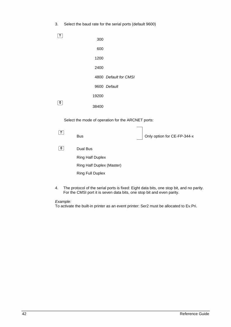
3. Select the baud rate for the serial ports (default 9600)
300
600
1200
2400
4800
Default for CMSI
9600
Default
19200
38400
Select the mode of operation for the ARCNET ports:
Bus
Only option for CE-FP-344-x
Dual Bus
Ring Half Duplex
Ring Half Duplex (Master)
Ring Full Duplex
4. The protocol of the serial ports is fixed: Eight data bits, one stop bit, and no parity. For the CMSI port it is seven data bits, one stop bit and even parity.
Example: To activate the built-in printer as an event printer: Ser2 must be allocated to Ev.Pri.
Reference Guide 43
5.1.16 Network menu
(COMMUNICATION, 2, )
NETWORK MENU
1 Panels 2 L-Repeaters3 G-Repeaters
0..9, <>, E, XAlarms : Faults : Cond. : P : S D Z
Return to Communication Menu Page 39
Select number or use and press
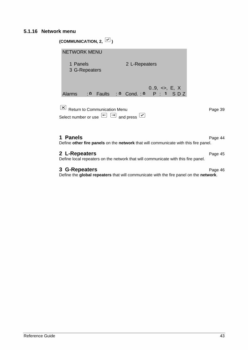
1 Panels Page 44 Define other fire panels on the network that will communicate with this fire panel.
2 L-Repeaters Page 45 Define local repeaters on the network that will communicate with this fire panel.
3 G-Repeaters Page 46 Define the global repeaters that will communicate with the fire panel on the network.
0 0 0 1
44 Reference Guide
5.1.17 Panels
(NETWORK, 1, )
PANELS
Panel No. :Status : disStart :End :
0..9, ^v, <>, E, XAlarms : Faults : Cond. : G : S D Z
Return to Network Menu Page 43
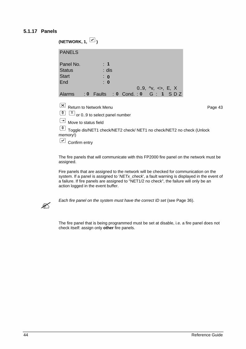
or 0..9 to select panel number
Move to status field
Toggle dis/NET1 check/NET2 check/ NET1 no check/NET2 no check (Unlock memory!)
Confirm entry
The fire panels that will communicate with this FP2000 fire panel on the network must be assigned.
Fire panels that are assigned to the network will be checked for communication on the system. If a panel is assigned to 'NETx_check', a fault warning is displayed in the event of a failure. If fire panels are assigned to "NET1/2 no check", the failure will only be an action logged in the event buffer.
Each fire panel on the system must have the correct ID set (see Page 36).
The fire panel that is being programmed must be set at disable, i.e. a fire panel does not check itself: assign only other fire panels.
1 0 0 0 0 0 1
Reference Guide 45
5.1.18 Local repeaters
(NETWORK, 2, )
LOCAL REPEATERS
L-Repeater No. :Status : NET1 check
0..9, ^v, <>, E, XAlarms : Faults : Cond. : P : S D Z
Return to Network Menu Page 43
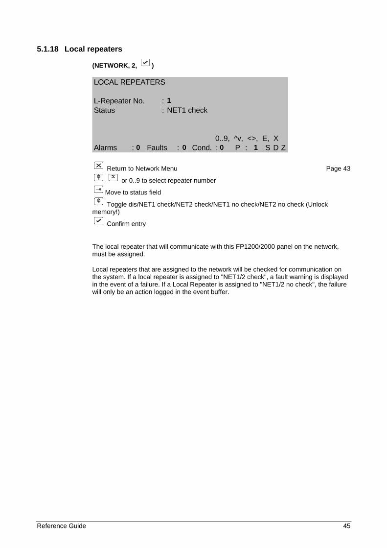
or 0..9 to select repeater number
Move to status field
Toggle dis/NET1 check/NET2 check/NET1 no check/NET2 no check (Unlock memory!)
Confirm entry
The local repeater that will communicate with this FP1200/2000 panel on the network, must be assigned.
Local repeaters that are assigned to the network will be checked for communication on the system. If a local repeater is assigned to "NET1/2 check", a fault warning is displayed in the event of a failure. If a Local Repeater is assigned to "NET1/2 no check", the failure will only be an action logged in the event buffer.
1 0 0 0 1
46 Reference Guide
5.1.19 Global repeaters
(NETWORK, 3, )
GLOBAL REPEATERS
G-Repeater No. :Status : NET1 no check
0..9, ^v, <>, E, XAlarms : Faults : Cond. : P : S D Z
Return to Network Menu Page 43
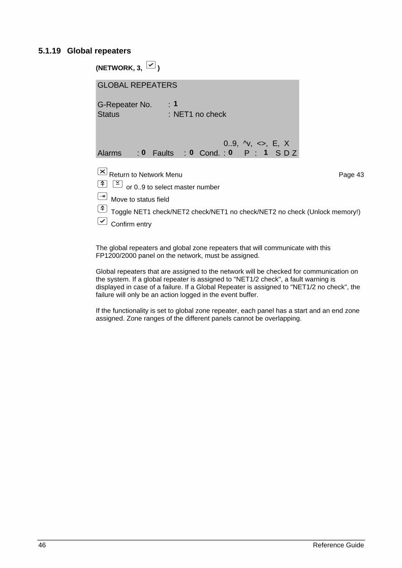
or 0..9 to select master number
Move to status field
Toggle NET1 check/NET2 check/NET1 no check/NET2 no check (Unlock memory!)
Confirm entry
The global repeaters and global zone repeaters that will communicate with this FP1200/2000 panel on the network, must be assigned.
Global repeaters that are assigned to the network will be checked for communication on the system. If a global repeater is assigned to "NET1/2 check", a fault warning is displayed in case of a failure. If a Global Repeater is assigned to "NET1/2 no check", the failure will only be an action logged in the event buffer.
If the functionality is set to global zone repeater, each panel has a start and an end zone assigned. Zone ranges of the different panels cannot be overlapping.
1 0 0 0 1
Reference Guide 47
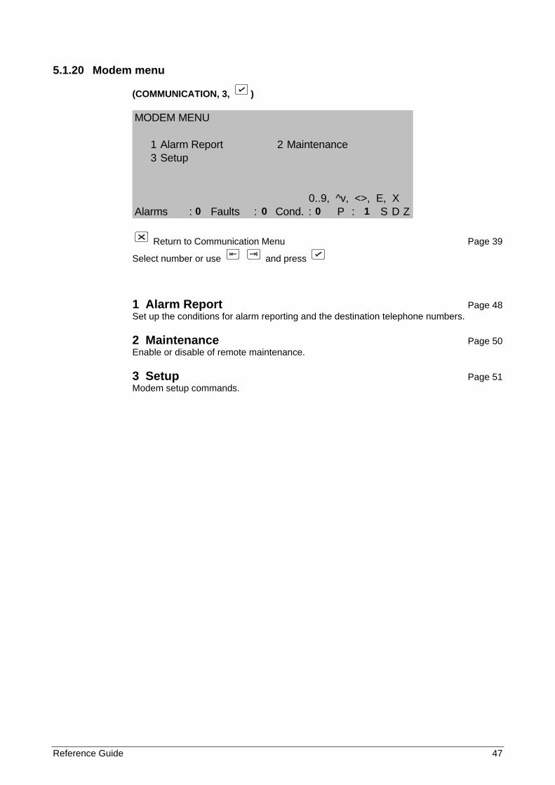
5.1.20 Modem menu
(COMMUNICATION, 3, )
MODEM MENU
1 Alarm Report 2 Maintenance3 Setup
0..9, ^v, <>, E, XAlarms : Faults : Cond. : P : S D Z
Return to Communication Menu Page 39
Select number or use and press
1 Alarm Report Page 48 Set up the conditions for alarm reporting and the destination telephone numbers.
2 Maintenance Page 50 Enable or disable of remote maintenance.
3 Setup Page 51 Modem setup commands.
0 0 0 1
48 Reference Guide
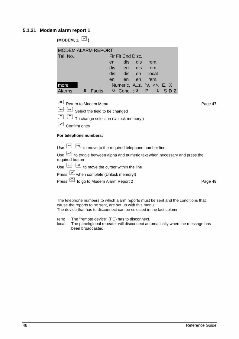
5.1.21 Modem alarm report 1
(MODEM, 1, )
MODEM ALARM REPORTTel. No. Fir Flt Cnd Disc.
en dis dis rem.dis en dis rem.dis dis en localen en en rem.
more Numeric, A..z, ^v, <>, E, XAlarms : Faults : Cond. : P : S D Z
Return to Modem Menu Page 47
Select the field to be changed
To change selection (Unlock memory!)
Confirm entry
For telephone numbers:
Use to move to the required telephone number line
Use to toggle between alpha and numeric text when necessary and press the required button
Use to move the cursor within the line
Press when complete (Unlock memory!)
Press to go to Modem Alarm Report 2 Page 49
The telephone numbers to which alarm reports must be sent and the conditions that cause the reports to be sent, are set up with this menu. The device that has to disconnect can be selected in the last column:
rem: The "remote device" (PC) has to disconnect. local: The panel/global repeater will disconnect automatically when the message has
been broadcasted.
0 0 0 1
Reference Guide 49
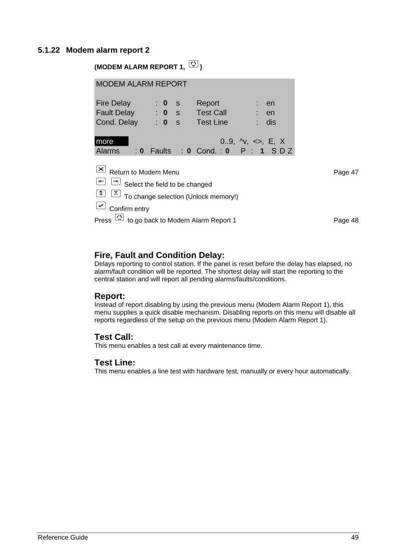
5.1.22 Modem alarm report 2
(MODEM ALARM REPORT 1, )
MODEM ALARM REPORT
Fire Delay : s Report : enFault Delay : s Test Call : enCond. Delay : s Test Line : dis
more 0..9, ^v, <>, E, XAlarms : Faults : Cond. : P : S D Z
Return to Modem Menu Page 47
Select the field to be changed
To change selection (Unlock memory!)
Confirm entry
Press to go back to Modem Alarm Report 1 Page 48
Fire, Fault and Condition Delay: Delays reporting to control station. If the panel is reset before the delay has elapsed, no alarm/fault condition will be reported. The shortest delay will start the reporting to the central station and will report all pending alarms/faults/conditions.
Report: Instead of report disabling by using the previous menu (Modem Alarm Report 1), this menu supplies a quick disable mechanism. Disabling reports on this menu will disable all reports regardless of the setup on the previous menu (Modem Alarm Report 1).
Test Call: This menu enables a test call at every maintenance time.
Test Line: This menu enables a line test with hardware test, manually or every hour automatically.
0 0 0 0 0 0 1
50 Reference Guide
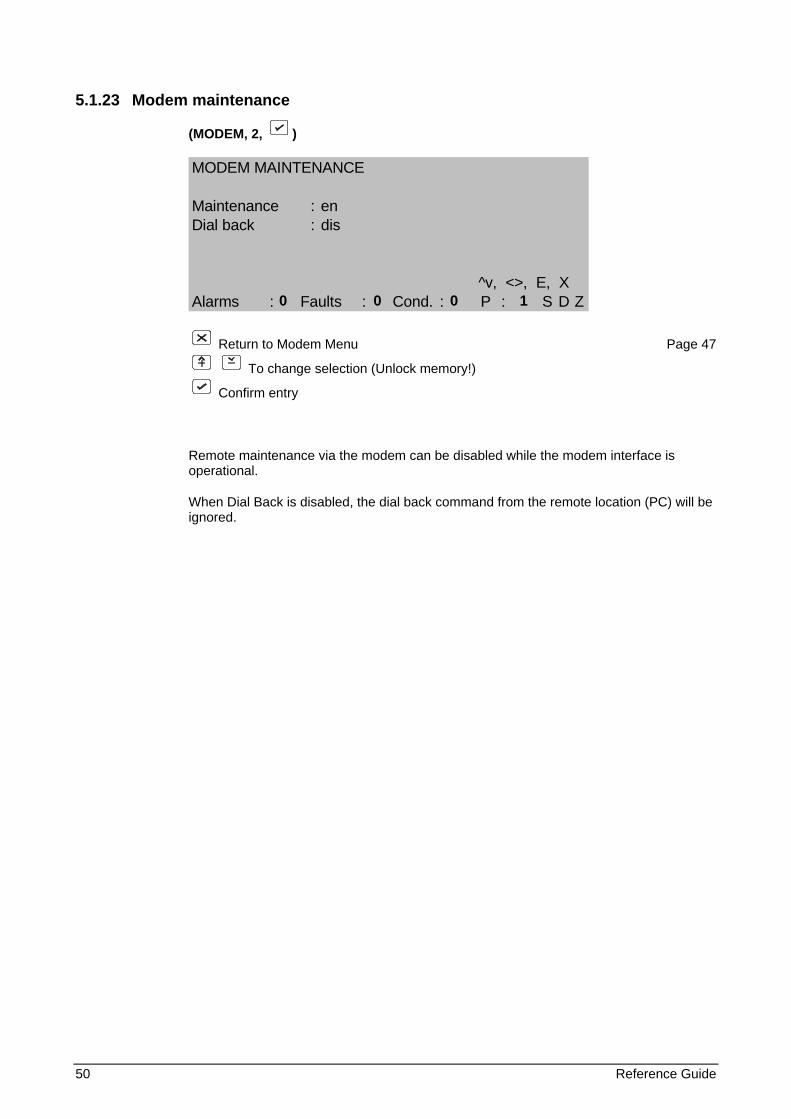
5.1.23 Modem maintenance
(MODEM, 2, )
MODEM MAINTENANCE
Maintenance : enDial back : dis
^v, <>, E, XAlarms : Faults : Cond. : P : S D Z
Return to Modem Menu Page 47
To change selection (Unlock memory!)
Confirm entry
Remote maintenance via the modem can be disabled while the modem interface is operational.
When Dial Back is disabled, the dial back command from the remote location (PC) will be ignored.
0 0 0 1
Reference Guide 51
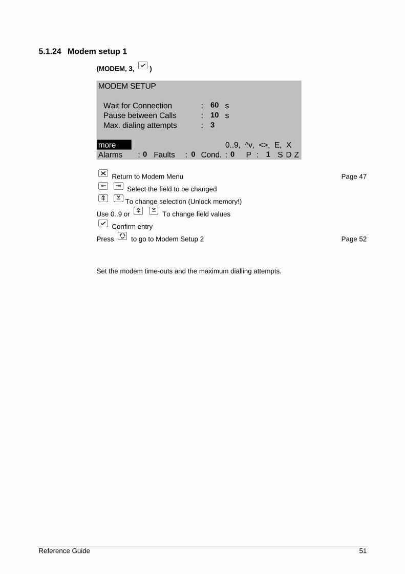
5.1.24 Modem setup 1
(MODEM, 3, )
MODEM SETUP
Wait for Connection : sPause between Calls : sMax. dialing attempts :
more 0..9, ^v, <>, E, XAlarms : Faults : Cond. : P : S D Z
Return to Modem Menu Page 47
Select the field to be changed
To change selection (Unlock memory!)
Use 0..9 or To change field values
Confirm entry
Press to go to Modem Setup 2 Page 52
Set the modem time-outs and the maximum dialling attempts.
60 10 3 0 0 0 1
52 Reference Guide
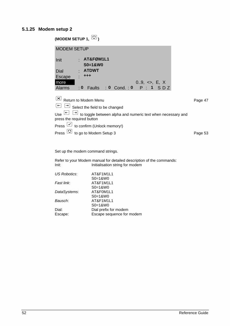
5.1.25 Modem setup 2
(MODEM SETUP 1, )
MODEM SETUP
Init :
Dial :Escape :more 0..9, <>, E, XAlarms : Faults : Cond. : P : S D Z
Return to Modem Menu Page 47
Select the field to be changed
Use to toggle between alpha and numeric text when necessary and press the required button
Press to confirm (Unlock memory!)
Press to go to Modem Setup 3 Page 53
Set up the modem command strings.
Refer to your Modem manual for detailed description of the commands: Init: Initialisation string for modem
US Robotics: AT&F1M1L1 S0=1&W0 Fast link: AT&F1M1L1 S0=1&W0 DataSystems: AT&F0M1L1 S0=1&W0 Bausch: AT&F1M1L1 S0=1&W0 Dial: Dial prefix for modem Escape: Escape sequence for modem
AT&FØM1L1 S0=1&W0 ATDWT +++ 0 0 0 1
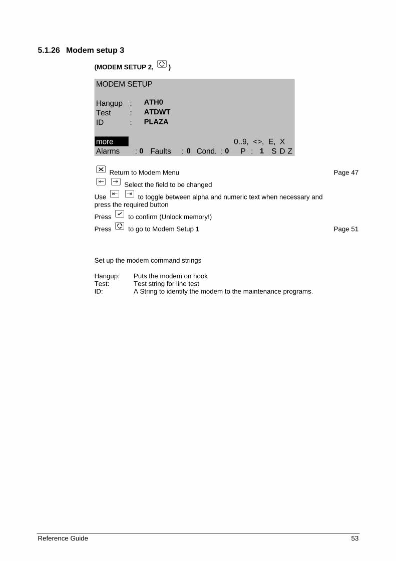
Reference Guide 53
5.1.26 Modem setup 3
(MODEM SETUP 2, )
MODEM SETUP
Hangup :Test :ID :
more 0..9, <>, E, XAlarms : Faults : Cond. : P : S D Z
Return to Modem Menu Page 47
Select the field to be changed
Use to toggle between alpha and numeric text when necessary and press the required button
Press to confirm (Unlock memory!)
Press to go to Modem Setup 1 Page 51
Set up the modem command strings
Hangup: Puts the modem on hook Test: Test string for line test ID: A String to identify the modem to the maintenance programs.
ATH0 ATDWT PLAZA 0 0 0 1
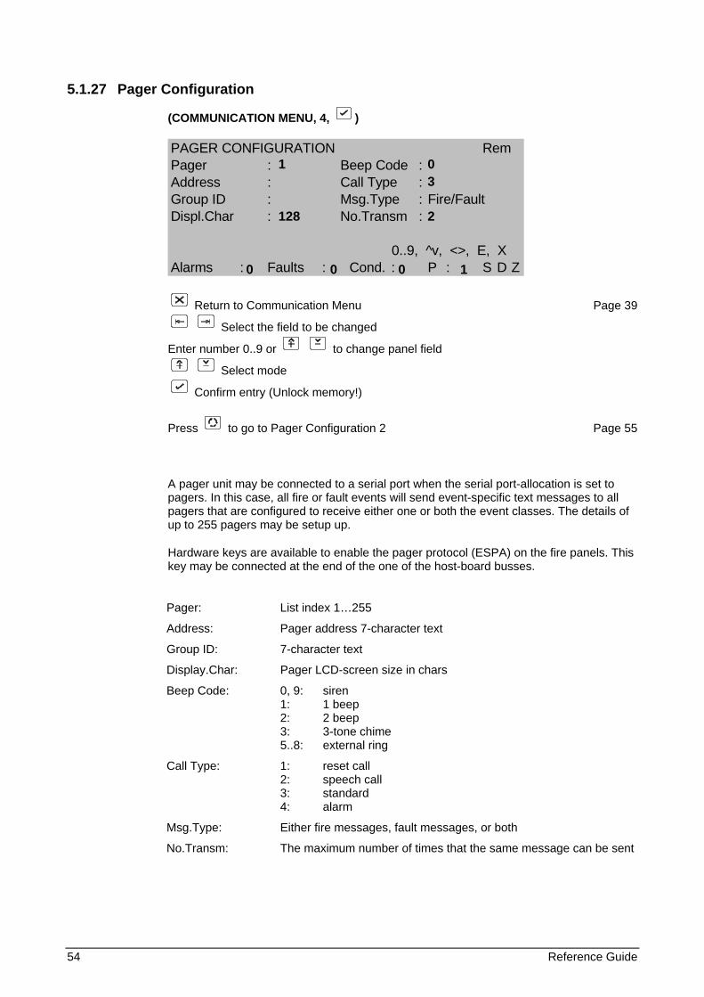
54 Reference Guide
5.1.27 Pager Configuration
(COMMUNICATION MENU, 4, )
PAGER CONFIGURATION RemPager : Beep Code :Address : Call Type :Group ID : Msg.Type : Fire/FaultDispl.Char : No.Transm :
0..9, ^v, <>, E, XAlarms : Faults : Cond. : P : S D Z
Return to Communication Menu Page 39
Select the field to be changed
Enter number 0..9 or to change panel field
Select mode
Confirm entry (Unlock memory!)
Press to go to Pager Configuration 2 Page 55
A pager unit may be connected to a serial port when the serial port-allocation is set to pagers. In this case, all fire or fault events will send event-specific text messages to all pagers that are configured to receive either one or both the event classes. The details of up to 255 pagers may be setup up.
Hardware keys are available to enable the pager protocol (ESPA) on the fire panels. This key may be connected at the end of the one of the host-board busses.
Pager: List index 1…255
Address: Pager address 7-character text
Group ID: 7-character text
Display.Char: Pager LCD-screen size in chars
Beep Code: 0, 9: siren 1: 1 beep 2: 2 beep 3: 3-tone chime 5..8: external ring
Call Type: 1: reset call 2: speech call 3: standard 4: alarm
Msg.Type: Either fire messages, fault messages, or both
No.Transm: The maximum number of times that the same message can be sent
1 0 3 128 2 0 0 0 1
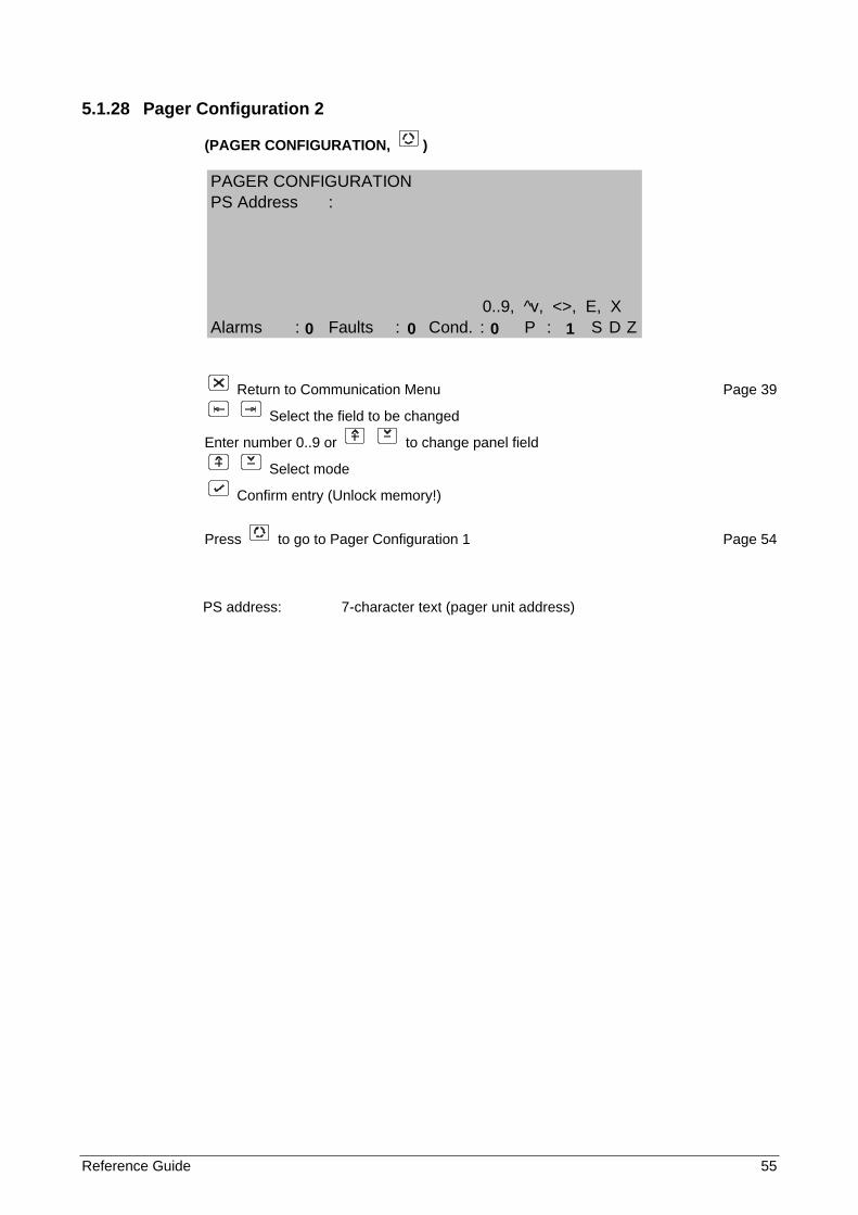
Reference Guide 55
5.1.28 Pager Configuration 2
(PAGER CONFIGURATION, )
Return to Communication Menu Page 39
Select the field to be changed
Enter number 0..9 or to change panel field
Select mode
Confirm entry (Unlock memory!)
Press to go to Pager Configuration 1 Page 54
PS address: 7-character text (pager unit address)
PAGER CONFIGURATIONPS Address :
0..9, ^v, <>, E, XAlarms : Faults : Cond. : P : S D Z
0 0 0 1
56 Reference Guide
5.1.29 LON Devices The LON device set-up screens consist of four screens. The first screen is the ‘LON Devices Set-up’ and displays the non-volatile memory. Any information stored in the non-volatile memory can only be cleared if the memory lock is unlocked. The sequence in which the data is displayed on this screen is the sequence used by the panel. The second screen is the ‘Service Pin List’ and is used to set-up the sequence in which the LON devices must be added to the non-volatile memory. The third screen is the ‘LON Node Map’ and displays all devices connected to the LON bus whether they belong to the own domain or a foreign domain. The fourth screen, ‘LON Fault Status’, is a debugging tool and shows the status of all inputs and/or outputs of a LON device installed on the device. Any FP700 module (from host version 7.xx) or FBP700 based product can be connected to a LON port of the FP1200/2000. Of these, 32 modules or devices can be uniquely identified by means of their Neuron ID.
For all LON device set-up screens the following abbreviations apply:
Type, FldType Type of device connected to that node e.g. FBP700. (Fld = Field)
ID, FldID Displays the node ID assigned to it
NID, FldNID Unique Neuron ID of the LON device. (If the service pin on a connected LON device is pressed the ‘NID’ field of that node will be highlighted)
Ver., FldVer. The version of software in the device
Mode The current mode of operation the device is configured as: Zone, Area, Device of i/o where applicable
ProdCode, FldProdCode Extra information regarding the type of device connected to the panel and is mainly an extra debugging tool.
H/W Rev., FldH/W Rev. Extra information regarding the type of device connected to the panel and is mainly an extra debugging tool.
OEM, FldOEM Extra information regarding the type of device connected to the panel and is mainly an extra debugging tool.
FldSeq The current position in the sequence of the selected device. The sequence is specified as a position out of the total number of LON devices selected. A number of 3/19 means that the current selected device is number 3 out of 19 devices.
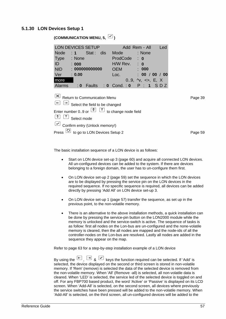
Reference Guide 57
5.1.30 LON Devices Setup 1
(COMMUNICATION MENU, 5, )
LON DEVICES SETUP Add Rem - All LedNode : Stat : dis Mode : NoneType : None ProdCode :ID : H/W Rev. :NID : OEM :Ver : Loc. : / /more 0..9, ^v, <>, E, XAlarms : Faults : Cond. : P : S D Z
Return to Communication Menu Page 39
Select the field to be changed
Enter number 0..9 or to change node field
Select mode
Confirm entry (Unlock memory!)
Press to go to LON Devices Setup 2 Page 59
The basic installation sequence of a LON device is as follows:
• Start on LON device set-up 3 (page 60) and acquire all connected LON devices. All un-configured devices can be added to the system. If there are devices belonging to a foreign domain, the user has to un-configure them first.
• On LON device set-up 2 (page 59) set the sequence in which the LON devices are to be displayed by pressing the service pin on the LON devices in the required sequence. If no specific sequence is required, all devices can be added directly by pressing ‘Add All’ on LON device set-up 3.
• On LON device set-up 1 (page 57) transfer the sequence, as set up in the previous point, to the non-volatile memory.
• There is an alternative to the above installation methods, a quick installation can be done by pressing the service-pin button on the LON2000 module while the memory is unlocked and the service-switch is active. The sequence of tasks is as follow: first all nodes on the Lon-bus are un-configured and the none-volatile memory is cleared, then the all nodes are mapped and the node-ids of all the controller-nodes on the Lon-bus are resolved. Lastly all nodes are added in the sequence they appear on the map.
Refer to page 63 for a step-by-step installation example of a LON device
By using the , & keys the function required can be selected. If ‘Add’ is selected, the device displayed on the second or third screen is stored in non-volatile memory. If 'Rem' (remove) is selected the data of the selected device is removed from the non-volatile memory. When 'All' (Remove -all) is selected, all non-volatile data is cleared. When ‘LED’ is selected, the service led of the selected device is toggled on and off. For any FBP700 based product, the word ‘Active’ or ‘Passive’ is displayed on its LCD screen. When ‘Add-All’ is selected, on the second screen, all devices where previously the service switches have been pressed will be added to the non-volatile memory. When ‘Add-All’ is selected, on the third screen, all un-configured devices will be added to the
1 0 000 0 000000000000 000 0.00 00 00 00 0 0 0 1
58 Reference Guide
non-volatile memory. If ‘Clr’ (Clear) is selected on the second screen, all nodes on the service pin list are cleared.
The status of any of the 32 nodes can be set to either ‘en’ (enable) or ‘dis’ (disable). If a node is set to disable and a module was assigned to that node previously; the panel will indicate a condition.
The following types of devices can be connected the LON port:
FC700: FP700 Front CPU card FCD700: FP700 Front CPU card with display SD700: FP700 Sounder card ZE708: FP700 Zone Indicating Module ZI708: FP700 Zone Input Module PS700: FP700 Power Supply SIB716: FP700 Supervised Input board OCB724: FP700 Open Collector board SOB708: FP700 Supervised Output board FM740: Fireman’s Panel FBP700: Repeater Panel (For older versions of the FBP700) FBP700-D: Dutch Repeater Panel FRP700-S: Scandinavian Repeater Panel FRL700: Local LCD Repeater FRD700: Fire Brigade Delay Panel RB700: FP700 Relay card NC771: Network Card If a FP700 module is configured on the LON port, the location (LOC) of the board can be saved here to make future reference easier.
LOC: 04/02/03
04 - Refers to the enclosure the module is located 02 - Refers to the bucket in the enclosure 03 - Refers to the slot in the bucket
Note: When the redundant bits on a NC771 module are reset and the module is connected to a redundant network the whole LON-network freezes until the one side of the network is opened. When the FP2000 panel un-configures a NC771 module it sets the redundant bits by default, but the module can be un-configured by another system and then the redundant bits may not be set.
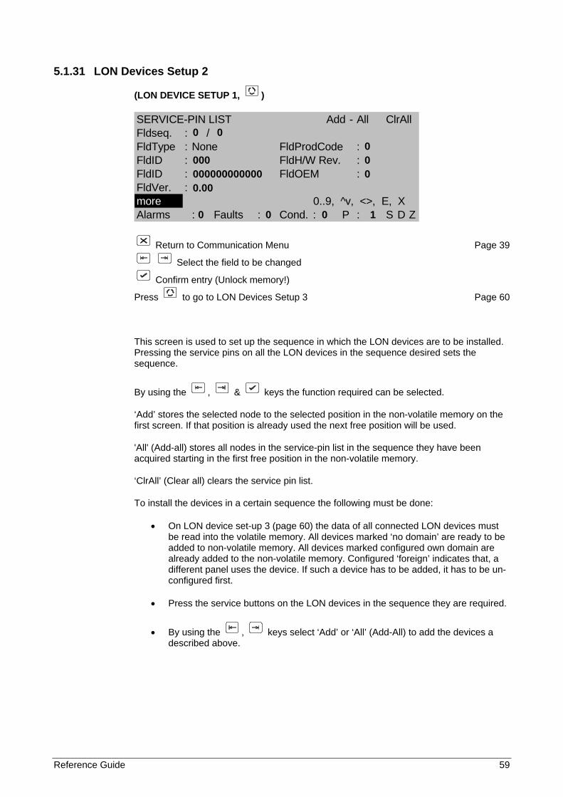
Reference Guide 59
5.1.31 LON Devices Setup 2
(LON DEVICE SETUP 1, )
SERVICE-PIN LIST Add - All ClrAllFldseq. : /FldType : None FldProdCode :FldID : FldH/W Rev. :FldID : FldOEM :FldVer. :more 0..9, ^v, <>, E, XAlarms : Faults : Cond. : P : S D Z
Return to Communication Menu Page 39
Select the field to be changed
Confirm entry (Unlock memory!)
Press to go to LON Devices Setup 3 Page 60
This screen is used to set up the sequence in which the LON devices are to be installed. Pressing the service pins on all the LON devices in the sequence desired sets the sequence.
By using the , & keys the function required can be selected.
‘Add’ stores the selected node to the selected position in the non-volatile memory on the first screen. If that position is already used the next free position will be used.
'All' (Add-all) stores all nodes in the service-pin list in the sequence they have been acquired starting in the first free position in the non-volatile memory.
‘ClrAll’ (Clear all) clears the service pin list.
To install the devices in a certain sequence the following must be done:
• On LON device set-up 3 (page 60) the data of all connected LON devices must be read into the volatile memory. All devices marked ‘no domain’ are ready to be added to non-volatile memory. All devices marked configured own domain are already added to the non-volatile memory. Configured ‘foreign’ indicates that, a different panel uses the device. If such a device has to be added, it has to be un-configured first.
• Press the service buttons on the LON devices in the sequence they are required.
• By using the , keys select ‘Add’ or ‘All’ (Add-All) to add the devices a described above.
0 0 0 000 0 000000000000 0 0.00 0 0 0 1
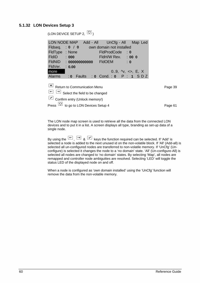
60 Reference Guide
5.1.32 LON Devices Setup 3
(LON DEVICE SETUP 2, )
LON NODE MAP Add - All UnCfg - All Map LedFldseq. : / own domain not installedFldType : None FldProdCode :FldID : FldH/W Rev. :FldNID : FldOEM :FldVer. :more 0..9, ^v, <>, E, XAlarms : Faults : Cond. : P : S D Z
Return to Communication Menu Page 39
Select the field to be changed
Confirm entry (Unlock memory!)
Press to go to LON Devices Setup 4 Page 61
The LON node map screen is used to retrieve all the data from the connected LON devices and to put it in a list. A screen displays all type, branding as set-up data of a single node.
By using the , & keys the function required can be selected. If ‘Add’ is selected a node is added to the next unused id on the non-volatile block. If 'All' (Add-all) is selected all un-configured nodes are transferred to non-volatile memory. If ‘UnCfg’ (Un-configure) is selected it changes the node to a ‘no domain’ state. ‘All’ (Un-configure-All) is selected all nodes are changed to ‘no domain’ states. By selecting ‘Map’, all nodes are remapped and controller node ambiguities are resolved. Selecting ‘LED’ will toggle the status LED of the displayed node on and off.
When a node is configured as ‘own domain installed’ using the ‘UnCfg’ function will remove the data from the non-volatile memory.
0 0 0 000 00 0 000000000000 0 0.00 0 0 0 1
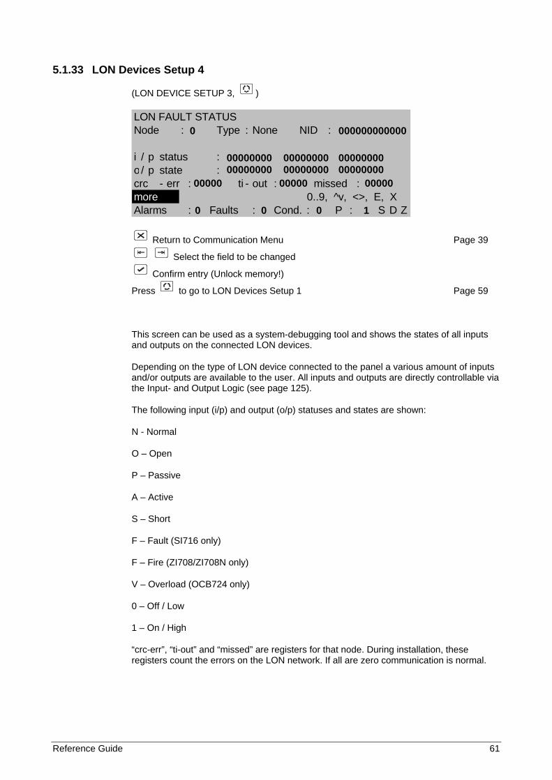
Reference Guide 61
5.1.33 LON Devices Setup 4
(LON DEVICE SETUP 3, )
LON FAULT STATUSNode : Type : None NID :
i / p status :o/ p state :crc - err : ti - out : missed :more 0..9, ^v, <>, E, XAlarms : Faults : Cond. : P : S D Z
Return to Communication Menu Page 39
Select the field to be changed
Confirm entry (Unlock memory!)
Press to go to LON Devices Setup 1 Page 59
This screen can be used as a system-debugging tool and shows the states of all inputs and outputs on the connected LON devices.
Depending on the type of LON device connected to the panel a various amount of inputs and/or outputs are available to the user. All inputs and outputs are directly controllable via the Input- and Output Logic (see page 125).
The following input (i/p) and output (o/p) statuses and states are shown:
N - Normal
O – Open
P – Passive
A – Active
S – Short
F – Fault (SI716 only)
F – Fire (ZI708/ZI708N only)
V – Overload (OCB724 only)
0 – Off / Low
1 – On / High
“crc-err”, “ti-out” and “missed” are registers for that node. During installation, these registers count the errors on the LON network. If all are zero communication is normal.
0 000000000000 00000000 00000000 00000000 00000000 00000000 00000000 00000 00000 00000 0 0 0 1
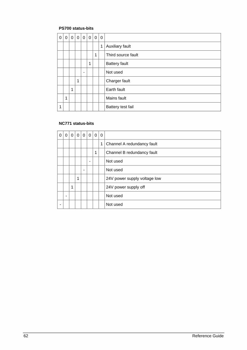
62 Reference Guide
PS700 status-bits
0 0 0 0 0 0 0 0
1 Auxiliary fault
1 Third source fault
1 Battery fault
- Not used
1 Charger fault
1 Earth fault
1 Mains fault
1 Battery test fail
NC771 status-bits
0 0 0 0 0 0 0 0
1 Channel A redundancy fault
1 Channel B redundancy fault
- Not used
- Not used
1 24V power supply voltage low
1 24V power supply off
- Not used
- Not used
Reference Guide 63
5.1.34 Step-by-step LON device installation walkthrough Any LON device or -module can be connected to a FP1200/2000 fire panel via a LON2000 module. Here is a step-by-step installation example for the FBP700:
1. Connect the FBP700 to the FP1200/2000 (24V to supply, communication to LON2000)
2. Enable the LON port (Enabled as a default if a LON2000 is detected)
Entry Code / 1-System / 1-Configuration / 4-Communication / 1-Port Setup
Toggle Port to LON
Toggle Allocation to LON
3. Install the FBP700
Entry Code / 1-System / 1-Configuration / 4-Communication / 5-LON Devices
Press “MORE” to go to the third screen of the LON Devices Setup
Select Add
4. Press the service switch on FBP700
Fldseq: 1/1
FldType: FBP700
FldId: 001
FldNID: 48-bit ID number unique to a node.
Ver: 1.09 (Depending on which version of firmware is in the module)
5. If the information appears as in ‘4’ above, press “MORE” to go to the second screen of the LON Devices Setup.
Select Add
Press Enter.
The information in (4) moves to the first screen of the LON devices set-up
Note: If the selected node on the first screen shows "type: none", then the FBP is installed there. If that node is already in use the FBP is installed in the next un-used node.
6. Reset the panel
7. The FBP700 is installed.
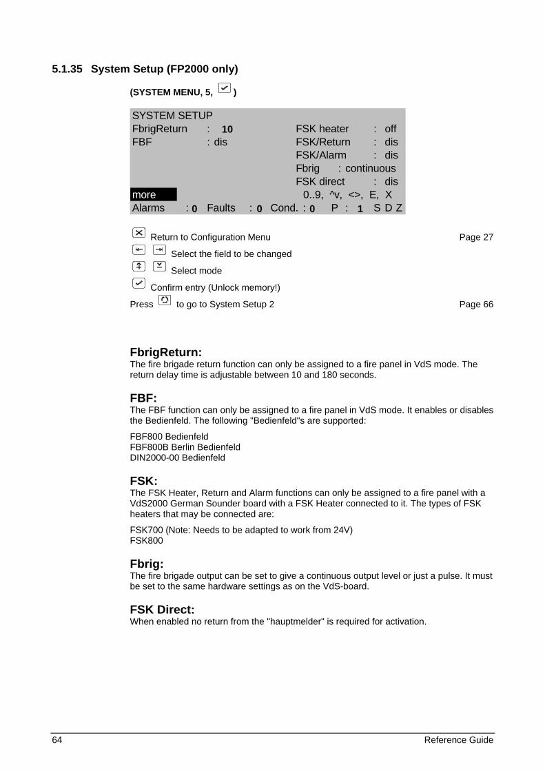
64 Reference Guide
5.1.35 System Setup (FP2000 only)
(SYSTEM MENU, 5, )
SYSTEM SETUPFbrigReturn : FSK heater : offFBF : dis FSK/Return : dis
FSK/Alarm : disFbrig : continuousFSK direct : dis
more 0..9, ^v, <>, E, XAlarms : Faults : Cond. : P : S D Z
Return to Configuration Menu Page 27
Select the field to be changed
Select mode
Confirm entry (Unlock memory!)
Press to go to System Setup 2 Page 66
FbrigReturn: The fire brigade return function can only be assigned to a fire panel in VdS mode. The return delay time is adjustable between 10 and 180 seconds.
FBF: The FBF function can only be assigned to a fire panel in VdS mode. It enables or disables the Bedienfeld. The following "Bedienfeld"s are supported:
FBF800 Bedienfeld FBF800B Berlin Bedienfeld DIN2000-00 Bedienfeld
FSK: The FSK Heater, Return and Alarm functions can only be assigned to a fire panel with a VdS2000 German Sounder board with a FSK Heater connected to it. The types of FSK heaters that may be connected are:
FSK700 (Note: Needs to be adapted to work from 24V) FSK800
Fbrig: The fire brigade output can be set to give a continuous output level or just a pulse. It must be set to the same hardware settings as on the VdS-board.
FSK Direct: When enabled no return from the "hauptmelder" is required for activation.
10 0 0 0 1
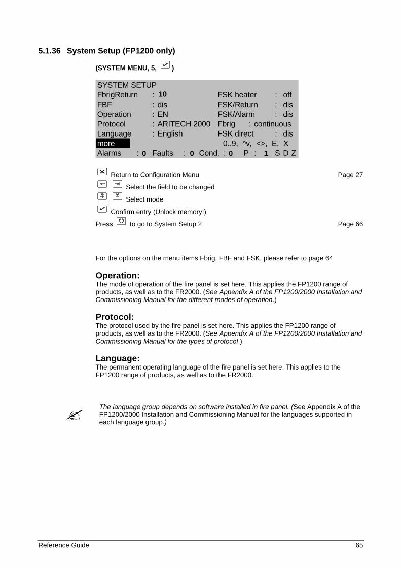
Reference Guide 65
5.1.36 System Setup (FP1200 only)
(SYSTEM MENU, 5, )
SYSTEM SETUPFbrigReturn : FSK heater : offFBF : dis FSK/Return : disOperation : EN FSK/Alarm : disProtocol : ARITECH 2000 Fbrig : continuousLanguage : English FSK direct : dismore 0..9, ^v, <>, E, XAlarms : Faults : Cond. : P : S D Z
Return to Configuration Menu Page 27
Select the field to be changed
Select mode
Confirm entry (Unlock memory!)
Press to go to System Setup 2 Page 66
For the options on the menu items Fbrig, FBF and FSK, please refer to page 64
Operation: The mode of operation of the fire panel is set here. This applies the FP1200 range of products, as well as to the FR2000. (See Appendix A of the FP1200/2000 Installation and Commissioning Manual for the different modes of operation.)
Protocol: The protocol used by the fire panel is set here. This applies the FP1200 range of products, as well as to the FR2000. (See Appendix A of the FP1200/2000 Installation and Commissioning Manual for the types of protocol.)
Language: The permanent operating language of the fire panel is set here. This applies to the FP1200 range of products, as well as to the FR2000.
The language group depends on software installed in fire panel. (See Appendix A of the FP1200/2000 Installation and Commissioning Manual for the languages supported in each language group.)
10 0 0 0 1
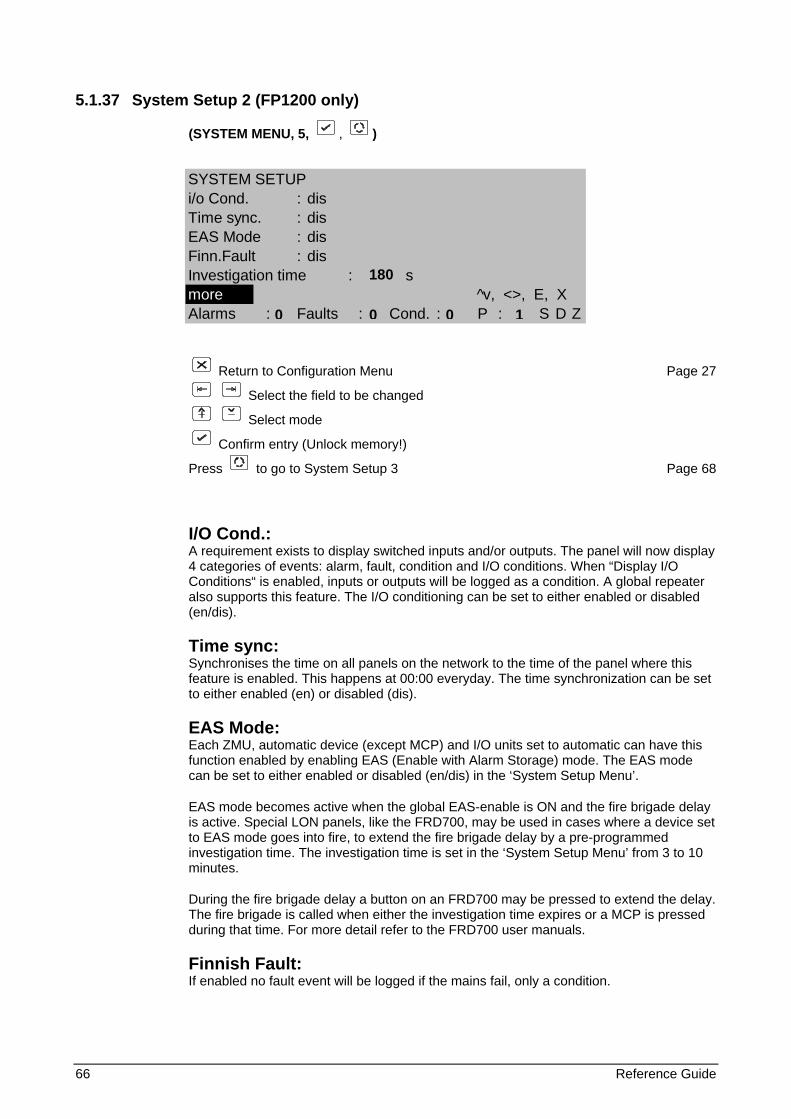
66 Reference Guide
5.1.37 System Setup 2 (FP1200 only)
(SYSTEM MENU, 5, , )
Return to Configuration Menu Page 27
Select the field to be changed
Select mode
Confirm entry (Unlock memory!)
Press to go to System Setup 3 Page 68
I/O Cond.: A requirement exists to display switched inputs and/or outputs. The panel will now display 4 categories of events: alarm, fault, condition and I/O conditions. When “Display I/O Conditions“ is enabled, inputs or outputs will be logged as a condition. A global repeater also supports this feature. The I/O conditioning can be set to either enabled or disabled (en/dis).
Time sync: Synchronises the time on all panels on the network to the time of the panel where this feature is enabled. This happens at 00:00 everyday. The time synchronization can be set to either enabled (en) or disabled (dis).
EAS Mode: Each ZMU, automatic device (except MCP) and I/O units set to automatic can have this function enabled by enabling EAS (Enable with Alarm Storage) mode. The EAS mode can be set to either enabled or disabled (en/dis) in the ‘System Setup Menu’.
EAS mode becomes active when the global EAS-enable is ON and the fire brigade delay is active. Special LON panels, like the FRD700, may be used in cases where a device set to EAS mode goes into fire, to extend the fire brigade delay by a pre-programmed investigation time. The investigation time is set in the ‘System Setup Menu’ from 3 to 10 minutes.
During the fire brigade delay a button on an FRD700 may be pressed to extend the delay. The fire brigade is called when either the investigation time expires or a MCP is pressed during that time. For more detail refer to the FRD700 user manuals.
Finnish Fault: If enabled no fault event will be logged if the mains fail, only a condition.
SYSTEM SETUPi/o Cond. : disTime sync. : disEAS Mode : disFinn.Fault : disInvestigation time : smore ^v, <>, E, XAlarms : Faults : Cond. : P : S D Z
180
0 0 0 1

Reference Guide 67
Investigation time (mode): The investigation time extends the Fire Brigade delay by a programmable time. It only works if the Fire Brigade delay is enabled and a value is set. The investigation time can be set to any value between 180 seconds and 600 seconds. This gives the user a predetermined time delay to investigate the alarm. When the time delay has expired all normal fire reporting is initiated.
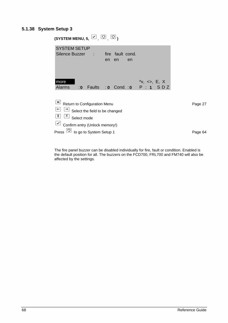
68 Reference Guide
5.1.38 System Setup 3
(SYSTEM MENU, 5, , , )
Return to Configuration Menu Page 27
Select the field to be changed
Select mode
Confirm entry (Unlock memory!)
Press to go to System Setup 1 Page 64
The fire panel buzzer can be disabled individually for fire, fault or condition. Enabled is the default position for all. The buzzers on the FCD700, FRL700 and FM740 will also be affected by the settings.
SYSTEM SETUPSilence Buzzer : fire fault cond.
en en en
more ^v, <>, E, XAlarms : Faults : Cond. : P : S D Z
0 0 0 1
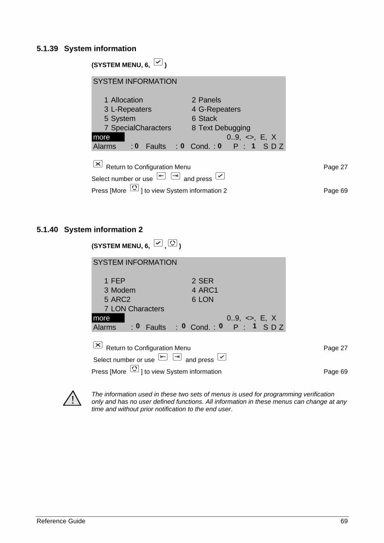
Reference Guide 69
5.1.39 System information
(SYSTEM MENU, 6, )
SYSTEM INFORMATION
1 Allocation 2 Panels3 L-Repeaters 4 G-Repeaters5 System 6 Stack7 SpecialCharacters 8 Text Debugging
more 0..9, <>, E, XAlarms : Faults : Cond. : P : S D Z
Return to Configuration Menu Page 27
Select number or use and press
Press [More ] to view System information 2 Page 69
5.1.40 System information 2
(SYSTEM MENU, 6, , )
SYSTEM INFORMATION
1 FEP 2 SER3 Modem 4 ARC15 ARC2 6 LON7 LON Characters
more 0..9, <>, E, XAlarms : Faults : Cond. : P : S D Z
Return to Configuration Menu Page 27
Select number or use and press
Press [More ] to view System information Page 69
! The information used in these two sets of menus is used for programming verification only and has no user defined functions. All information in these menus can change at any time and without prior notification to the end user.
0 0 0 1
0 0 0 1
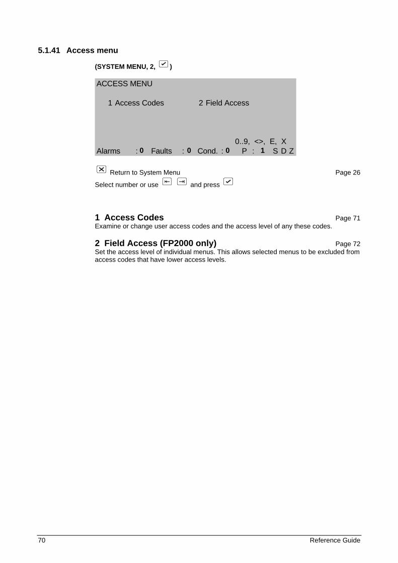
70 Reference Guide
5.1.41 Access menu
(SYSTEM MENU, 2, )
ACCESS MENU
1 Access Codes 2 Field Access
0..9, <>, E, XAlarms : Faults : Cond. : P : S D Z
Return to System Menu Page 26
Select number or use and press
1 Access Codes Page 71 Examine or change user access codes and the access level of any these codes.
2 Field Access (FP2000 only) Page 72 Set the access level of individual menus. This allows selected menus to be excluded from access codes that have lower access levels.
0 0 0 1
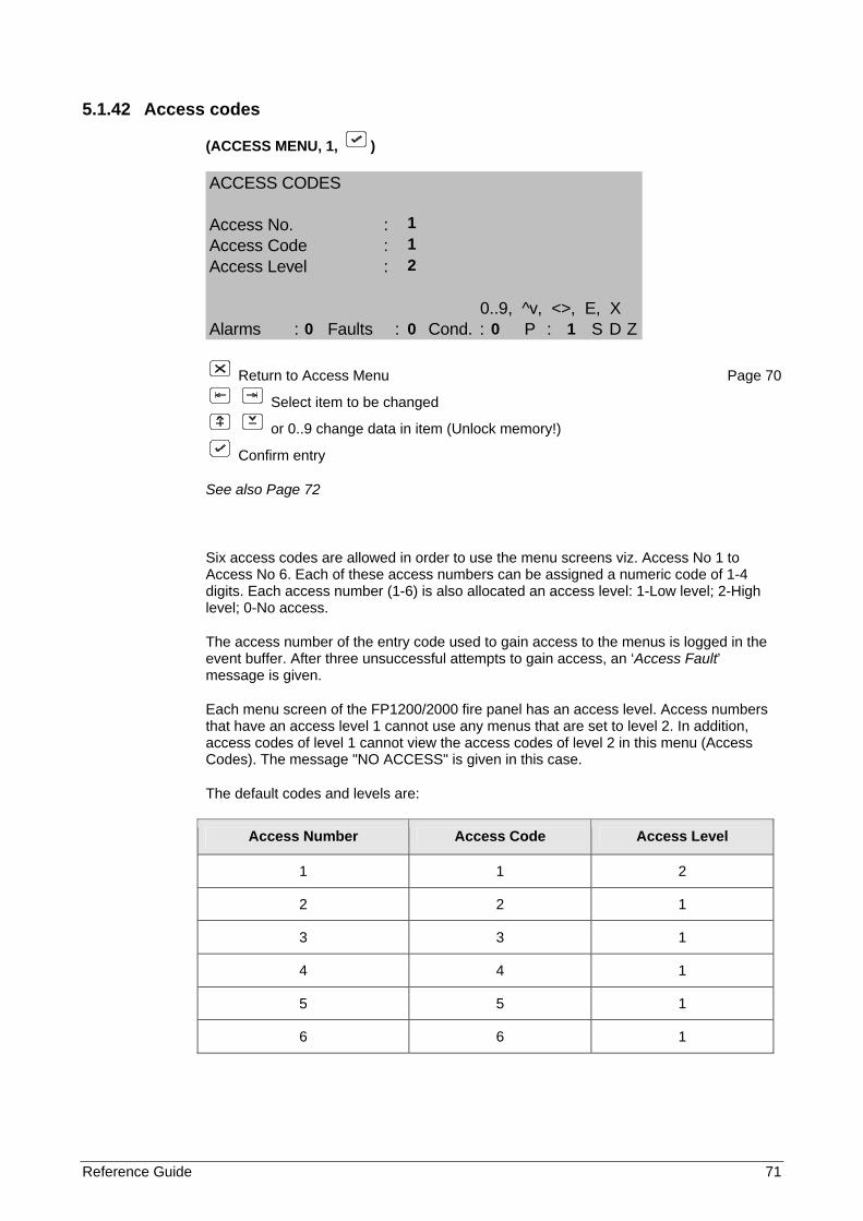
Reference Guide 71
5.1.42 Access codes
(ACCESS MENU, 1, )
ACCESS CODES
Access No. :Access Code :Access Level :
0..9, ^v, <>, E, XAlarms : Faults : Cond. : P : S D Z
Return to Access Menu Page 70
Select item to be changed
or 0..9 change data in item (Unlock memory!)
Confirm entry
See also Page 72
Six access codes are allowed in order to use the menu screens viz. Access No 1 to Access No 6. Each of these access numbers can be assigned a numeric code of 1-4 digits. Each access number (1-6) is also allocated an access level: 1-Low level; 2-High level; 0-No access.
The access number of the entry code used to gain access to the menus is logged in the event buffer. After three unsuccessful attempts to gain access, an ‘Access Fault’ message is given.
Each menu screen of the FP1200/2000 fire panel has an access level. Access numbers that have an access level 1 cannot use any menus that are set to level 2. In addition, access codes of level 1 cannot view the access codes of level 2 in this menu (Access Codes). The message "NO ACCESS" is given in this case.
The default codes and levels are:
Access Number Access Code Access Level
1 1 2
2 2 1
3 3 1
4 4 1
5 5 1
6 6 1
1 1 2 0 0 0 1
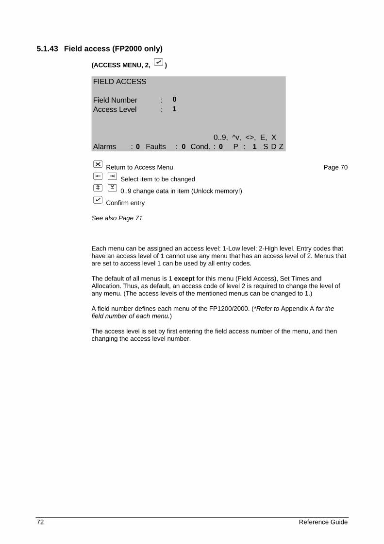
72 Reference Guide
5.1.43 Field access (FP2000 only)
(ACCESS MENU, 2, )
FIELD ACCESS
Field Number :Access Level :
0..9, ^v, <>, E, XAlarms : Faults : Cond. : P : S D Z
Return to Access Menu Page 70
Select item to be changed
0..9 change data in item (Unlock memory!)
Confirm entry
See also Page 71
Each menu can be assigned an access level: 1-Low level; 2-High level. Entry codes that have an access level of 1 cannot use any menu that has an access level of 2. Menus that are set to access level 1 can be used by all entry codes.
The default of all menus is 1 except for this menu (Field Access), Set Times and Allocation. Thus, as default, an access code of level 2 is required to change the level of any menu. (The access levels of the mentioned menus can be changed to 1.)
A field number defines each menu of the FP1200/2000. (*Refer to Appendix A for the field number of each menu.)
The access level is set by first entering the field access number of the menu, and then changing the access level number.
0 1 0 0 0 1
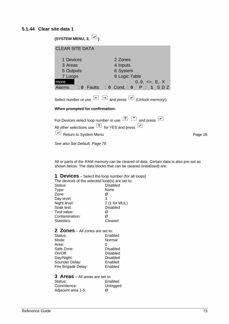
Reference Guide 73
5.1.44 Clear site data 1
(SYSTEM MENU, 3, )
CLEAR SITE DATA
1 Devices 2 Zones3 Areas 4 Inputs5 Outputs 6 System7 Loops 8 Logic Table
more 0..9, <>, E, XAlarms : Faults : Cond. : P : S D Z
Select number or use and press (Unlock memory!)
When prompted for confirmation:
For Devices select loop number or use and press
All other selections use for YES and press
Return to System Menu Page 26
See also Set Default, Page 76
All or parts of the RAM memory can be cleared of data. Certain data is also pre-set as shown below. The data blocks that can be cleared (initialised) are:
1 Devices – Select the loop number (for all loops) The devices of the selected loop(s) are set to: Status: Disabled Type: None Zone: Ø Day level: 3 Night level: 2 (1 for MUL) Soak test: Disabled Test value: Ø Contamination: Ø Statistics: Cleared
2 Zones – All zones are set to: Status: Enabled Mode: Normal Area: 0 Safe Zone: Disabled On/Off: Disabled Day/Night: Disabled Sounder Delay: Enabled Fire Brigade Delay: Enabled
3 Areas – All areas are set to: Status: Enabled Coincidence: Unlogged Adjacent area 1-5: Ø
0 0 0 1
74 Reference Guide
4 Inputs – All inputs are set to: Type: None
5 Outputs – All outputs are set to: Type: None
6 System Panel ID: 1/0 (for all Panels), 0/5 for the UN2011 Port: INT - set to FEP; Baud rate 9600 SER1 - set to Setup; Baud rate 9600 SER2 - set to None; Baud rate 9600 Other ports - function: None Network: Panels disabled Repeaters disabled Masters disabled Access codes: See Page 71 Field access: All menus have access level 1 except Field Access, Set Times and Allocation that have access level 2 Sounder/Fire Brigade Delay: 0 s All times: 00h00 Sounder off time, Zones on time and day mode time: Linked to none
7 Loops Loop data set to: Enabled
8 Logic table All logic instructions are cleared and an “END” is placed in line 1.
If any site data has been cleared, exiting the Site Data Screen will restart the panel.
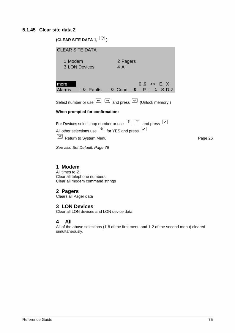
Reference Guide 75
5.1.45 Clear site data 2
(CLEAR SITE DATA 1, )
CLEAR SITE DATA
1 Modem 2 Pagers3 LON Devices 4 All
more 0..9, <>, E, XAlarms : Faults : Cond. : P : S D Z
Select number or use and press (Unlock memory!)
When prompted for confirmation:
For Devices select loop number or use and press
All other selections use for YES and press
Return to System Menu Page 26
See also Set Default, Page 76
1 Modem All times to Ø Clear all telephone numbers Clear all modem command strings
2 Pagers Clears all Pager data
3 LON Devices Clear all LON devices and LON device data
4 All All of the above selections (1-8 of the first menu and 1-2 of the second menu) cleared simultaneously.
0 0 0 1
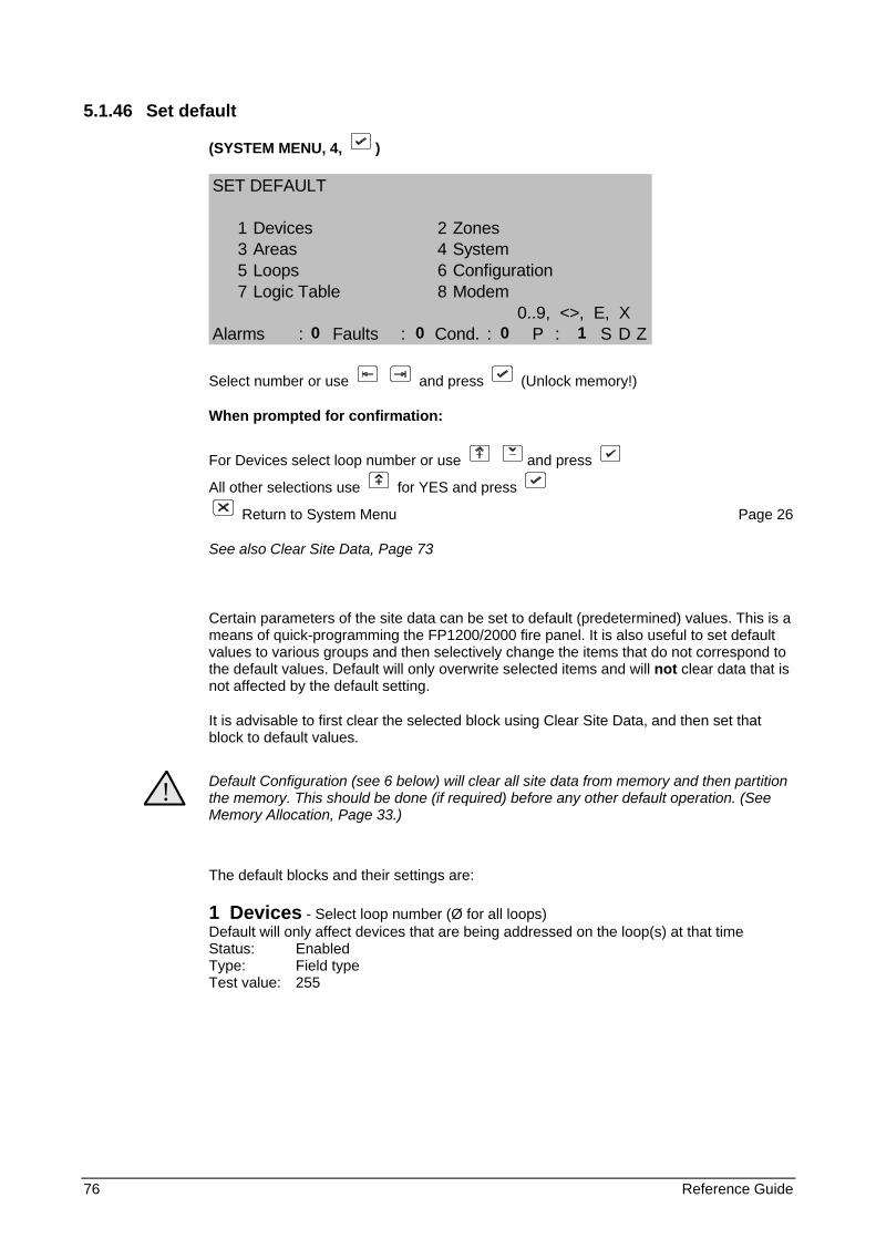
76 Reference Guide
5.1.46 Set default
(SYSTEM MENU, 4, )
SET DEFAULT
1 Devices 2 Zones3 Areas 4 System5 Loops 6 Configuration7 Logic Table 8 Modem
0..9, <>, E, XAlarms : Faults : Cond. : P : S D Z
Select number or use and press (Unlock memory!)
When prompted for confirmation:
For Devices select loop number or use and press
All other selections use for YES and press
Return to System Menu Page 26
See also Clear Site Data, Page 73
Certain parameters of the site data can be set to default (predetermined) values. This is a means of quick-programming the FP1200/2000 fire panel. It is also useful to set default values to various groups and then selectively change the items that do not correspond to the default values. Default will only overwrite selected items and will not clear data that is not affected by the default setting.
It is advisable to first clear the selected block using Clear Site Data, and then set that block to default values.
! Default Configuration (see 6 below) will clear all site data from memory and then partition the memory. This should be done (if required) before any other default operation. (See Memory Allocation, Page 33.)
The default blocks and their settings are:
1 Devices - Select loop number (Ø for all loops) Default will only affect devices that are being addressed on the loop(s) at that time Status: Enabled Type: Field type Test value: 255
0 0 0 1
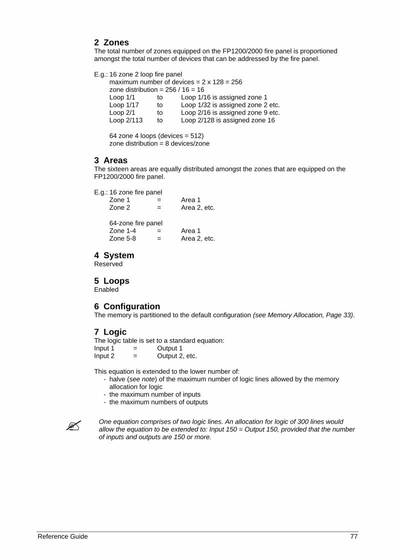
Reference Guide 77
2 Zones The total number of zones equipped on the FP1200/2000 fire panel is proportioned amongst the total number of devices that can be addressed by the fire panel.
E.g.: 16 zone 2 loop fire panel maximum number of devices = 2 x 128 = 256 zone distribution = 256 / 16 = 16 Loop 1/1 to Loop 1/16 is assigned zone 1 Loop 1/17 to Loop 1/32 is assigned zone 2 etc. Loop 2/1 to Loop 2/16 is assigned zone 9 etc. Loop 2/113 to Loop 2/128 is assigned zone 16
64 zone 4 loops (devices = 512) zone distribution = 8 devices/zone
3 Areas The sixteen areas are equally distributed amongst the zones that are equipped on the FP1200/2000 fire panel.
E.g.: 16 zone fire panel Zone 1 = Area 1 Zone 2 = Area 2, etc.
64-zone fire panel Zone 1-4 = Area 1 Zone 5-8 = Area 2, etc.
4 System Reserved
5 Loops Enabled
6 Configuration The memory is partitioned to the default configuration (see Memory Allocation, Page 33).
7 Logic The logic table is set to a standard equation: Input 1 = Output 1 Input 2 = Output 2, etc.
This equation is extended to the lower number of: - halve (see note) of the maximum number of logic lines allowed by the memory allocation for logic - the maximum number of inputs - the maximum numbers of outputs
One equation comprises of two logic lines. An allocation for logic of 300 lines would allow the equation to be extended to: Input 150 = Output 150, provided that the number of inputs and outputs are 150 or more.
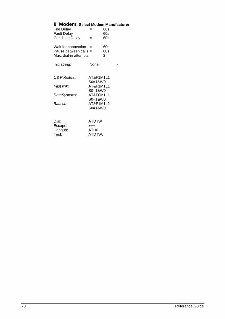
78 Reference Guide
8 Modem: Select Modem Manufacturer Fire Delay = 60s Fault Delay = 60s Condition Delay = 60s
Wait for connection = 60s Pause between calls = 60s Max. dial-in attempts = 3
Init. string: None: - - US Robotics: AT&F1M1L1 S0=1&W0 Fast link: AT&F1M1L1 S0=1&W0 DataSystems: AT&F0M1L1 S0=1&W0 Bausch: AT&F1M1L1 S0=1&W0
Dial: ATDTW Escape: +++ Hangup: ATH0 Test: ATDTW,
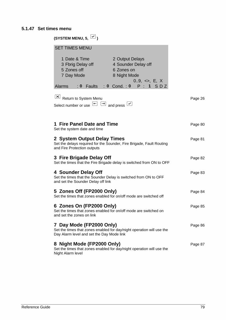
Reference Guide 79
5.1.47 Set times menu
(SYSTEM MENU, 5, )
SET TIMES MENU
1 Date & Time 2 Output Delays3 Fbrig Delay off 4 Sounder Delay off5 Zones off 6 Zones on7 Day Mode 8 Night Mode
0..9, <>, E, XAlarms : Faults : Cond. : P : S D Z
Return to System Menu Page 26
Select number or use and press
1 Fire Panel Date and Time Page 80 Set the system date and time
2 System Output Delay Times Page 81 Set the delays required for the Sounder, Fire Brigade, Fault Routing and Fire Protection outputs
3 Fire Brigade Delay Off Page 82 Set the times that the Fire Brigade delay is switched from ON to OFF
4 Sounder Delay Off Page 83 Set the times that the Sounder Delay is switched from ON to OFF and set the Sounder Delay off link
5 Zones Off (FP2000 Only) Page 84 Set the times that zones enabled for on/off mode are switched off
6 Zones On (FP2000 Only) Page 85 Set the times that zones enabled for on/off mode are switched on and set the zones on link
7 Day Mode (FP2000 Only) Page 86 Set the times that zones enabled for day/night operation will use the Day Alarm level and set the Day Mode link
8 Night Mode (FP2000 Only) Page 87 Set the times that zones enabled for day/night operation will use the Night Alarm level
0 0 0 1
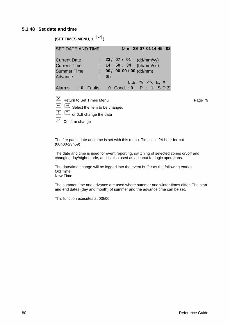
80 Reference Guide
5.1.48 Set date and time
(SET TIMES MENU, 1, )
SET DATE AND TIME Mon / / : :
Current Date : / / (dd/mm/yy)Current Time : : : (hh/mm/ss)Summer Time : / / (dd/mm)Advance : h
0..9, ^v, <>, E, XAlarms : Faults : Cond. : P : S D Z
Return to Set Times Menu Page 79
Select the item to be changed
or 0..9 change the data
Confirm change
The fire panel date and time is set with this menu. Time is in 24-hour format (00h00-23h59)
The date and time is used for event reporting, switching of selected zones on/off and changing day/night mode, and is also used as an input for logic operations.
The date/time change will be logged into the event buffer as the following entries: Old Time New Time
The summer time and advance are used where summer and winter times differ. The start and end dates (day and month) of summer and the advance time can be set.
This function executes at 03h00.
23 07 01 14 45 02 23 07 01 14 50 34 00 00 00 00 0 0 0 0 1
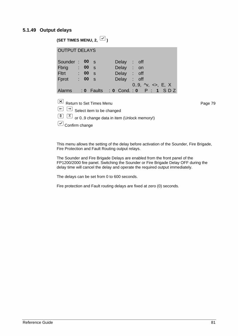
Reference Guide 81
5.1.49 Output delays
(SET TIMES MENU, 2, )
OUTPUT DELAYS
Sounder : s Delay : offFbrig : s Delay : onFltrt : s Delay : offFprot : s Delay : off
0..9, ^v, <>, E, XAlarms : Faults : Cond. : P : S D Z
Return to Set Times Menu Page 79
Select item to be changed
or 0..9 change data in item (Unlock memory!)
Confirm change
This menu allows the setting of the delay before activation of the Sounder, Fire Brigade, Fire Protection and Fault Routing output relays.
The Sounder and Fire Brigade Delays are enabled from the front panel of the FP1200/2000 fire panel. Switching the Sounder or Fire Brigade Delay OFF during the delay time will cancel the delay and operate the required output immediately.
The delays can be set from 0 to 600 seconds.
Fire protection and Fault routing delays are fixed at zero (0) seconds.
00 00 00 00 0 0 0 1
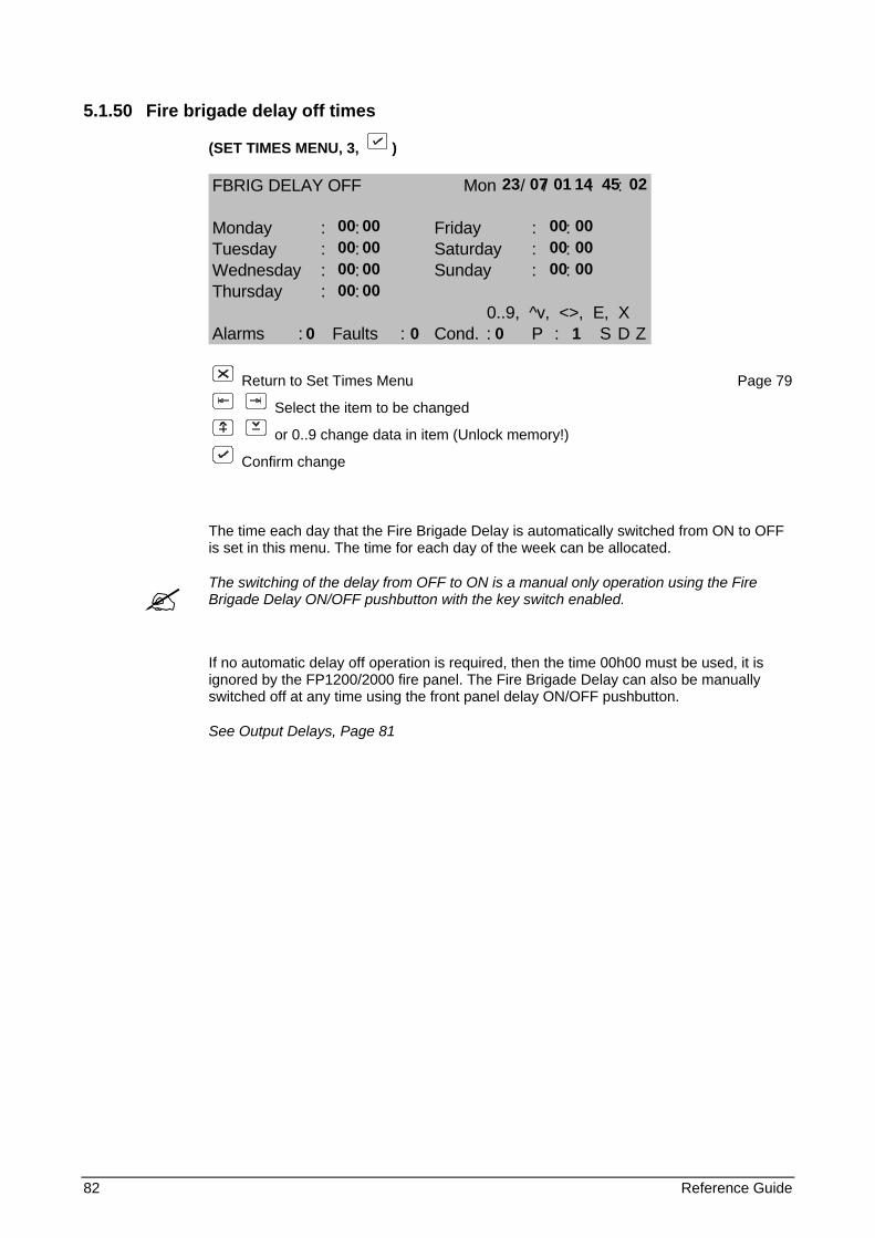
82 Reference Guide
5.1.50 Fire brigade delay off times
(SET TIMES MENU, 3, )
FBRIG DELAY OFF Mon / / : :
Monday : : Friday : :Tuesday : : Saturday : :Wednesday : : Sunday : :Thursday : :
0..9, ^v, <>, E, XAlarms : Faults : Cond. : P : S D Z
Return to Set Times Menu Page 79
Select the item to be changed
or 0..9 change data in item (Unlock memory!)
Confirm change
The time each day that the Fire Brigade Delay is automatically switched from ON to OFF is set in this menu. The time for each day of the week can be allocated.
The switching of the delay from OFF to ON is a manual only operation using the Fire Brigade Delay ON/OFF pushbutton with the key switch enabled.
If no automatic delay off operation is required, then the time 00h00 must be used, it is ignored by the FP1200/2000 fire panel. The Fire Brigade Delay can also be manually switched off at any time using the front panel delay ON/OFF pushbutton.
See Output Delays, Page 81
23 07 01 14 45 02 00 00 00 00 00 00 00 00 00 00 00 00 00 00 0 0 0 1
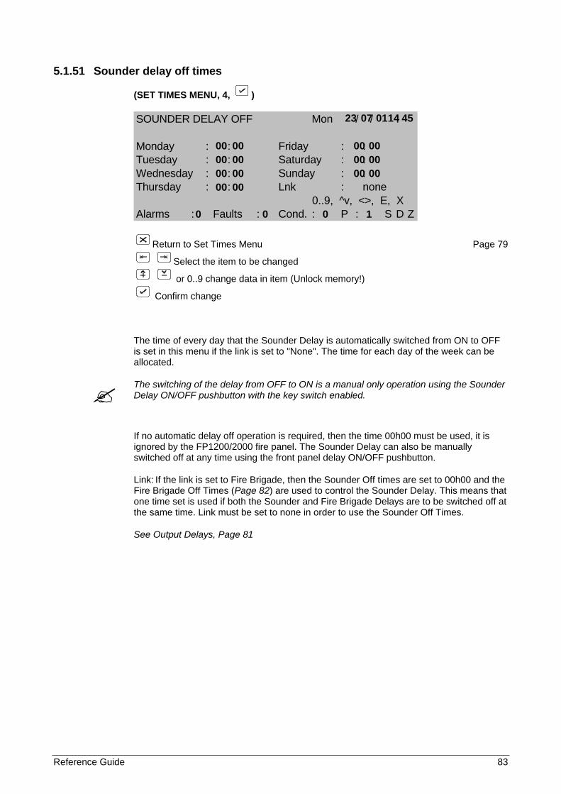
Reference Guide 83
5.1.51 Sounder delay off times
(SET TIMES MENU, 4, )
SOUNDER DELAY OFF Mon / / :
Monday : : Friday : :Tuesday : : Saturday : :Wednesday : : Sunday : :Thursday : : Lnk : none
0..9, ^v, <>, E, XAlarms : Faults : Cond. : P : S D Z
Return to Set Times Menu Page 79
Select the item to be changed
or 0..9 change data in item (Unlock memory!)
Confirm change
The time of every day that the Sounder Delay is automatically switched from ON to OFF is set in this menu if the link is set to "None". The time for each day of the week can be allocated.
The switching of the delay from OFF to ON is a manual only operation using the Sounder Delay ON/OFF pushbutton with the key switch enabled.
If no automatic delay off operation is required, then the time 00h00 must be used, it is ignored by the FP1200/2000 fire panel. The Sounder Delay can also be manually switched off at any time using the front panel delay ON/OFF pushbutton.
Link: If the link is set to Fire Brigade, then the Sounder Off times are set to 00h00 and the Fire Brigade Off Times (Page 82) are used to control the Sounder Delay. This means that one time set is used if both the Sounder and Fire Brigade Delays are to be switched off at the same time. Link must be set to none in order to use the Sounder Off Times.
See Output Delays, Page 81
23 07 01 14 45 00 00 00 00 00 00 00 00 00 00 00 00 00 00 0 0 0 1
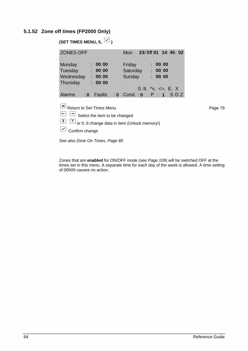
84 Reference Guide
5.1.52 Zone off times (FP2000 Only)
(SET TIMES MENU, 5, )
ZONES OFF Mon / / : :
Monday : : Friday : :Tuesday : : Saturday : :Wednesday : : Sunday : :Thursday : :
0..9, ^v, <>, E, XAlarms : Faults : Cond. : P : S D Z
Return to Set Times Menu Page 79
Select the item to be changed
or 0..9 change data in item (Unlock memory!)
Confirm change
See also Zone On Times, Page 85
Zones that are enabled for ON/OFF mode (see Page 109) will be switched OFF at the times set in this menu. A separate time for each day of the week is allowed. A time setting of 00h00 causes no action.
23 07 01 14 45 02 00 00 00 00 00 00 00 00 00 00 00 00 00 00 0 0 0 1
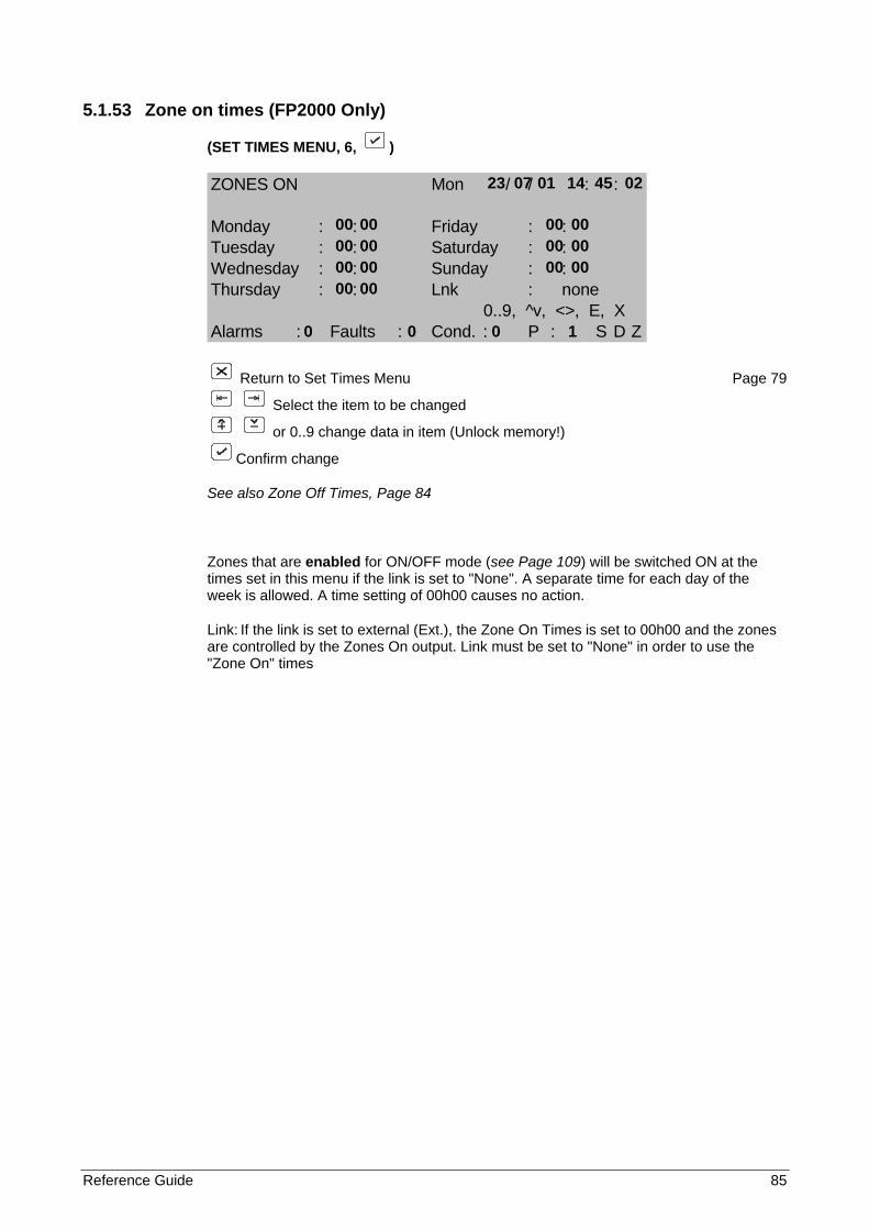
Reference Guide 85
5.1.53 Zone on times (FP2000 Only)
(SET TIMES MENU, 6, )
ZONES ON Mon / / : :
Monday : : Friday : :Tuesday : : Saturday : :Wednesday : : Sunday : :Thursday : : Lnk : none
0..9, ^v, <>, E, XAlarms : Faults : Cond. : P : S D Z
Return to Set Times Menu Page 79
Select the item to be changed
or 0..9 change data in item (Unlock memory!)
Confirm change
See also Zone Off Times, Page 84
Zones that are enabled for ON/OFF mode (see Page 109) will be switched ON at the times set in this menu if the link is set to "None". A separate time for each day of the week is allowed. A time setting of 00h00 causes no action.
Link: If the link is set to external (Ext.), the Zone On Times is set to 00h00 and the zones are controlled by the Zones On output. Link must be set to "None" in order to use the "Zone On" times
23 07 01 14 45 02 00 00 00 00 00 00 00 00 00 00 00 00 00 00 0 0 0 1
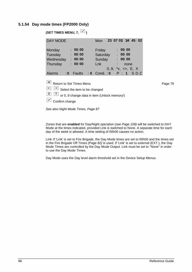
86 Reference Guide
5.1.54 Day mode times (FP2000 Only)
(SET TIMES MENU, 7, )
DAY MODE Mon / / :
Monday : : Friday : :Tuesday : : Saturday : :Wednesday : : Sunday : :Thursday : : Lnk : none
0..9, ^v, <>, E, XAlarms : Faults : Cond. : P : S D Z
Return to Set Times Menu Page 79
Select the item to be changed
or 0..9 change data in item (Unlock memory!)
Confirm change
See also Night Mode Times, Page 87
Zones that are enabled for Day/Night operation (see Page 109) will be switched to DAY Mode at the times indicated, provided Link is switched to None. A separate time for each day of the week is allowed. A time setting of 00h00 causes no action.
Link: If 'Link' is set to Fire Brigade, the Day Mode times are set to 00h00 and the times set in the Fire Brigade Off Times (Page 82) is used. If 'Link' is set to external (EXT.), the Day Mode Times are controlled by the Day Mode Output. Link must be set to "None" in order to use the Day Mode Times.
Day Mode uses the Day level alarm threshold set in the Device Setup Menus.
23 07 01 14 45 02 00 00 00 00 00 00 00 00 00 00 00 00 00 00 0 0 0 1
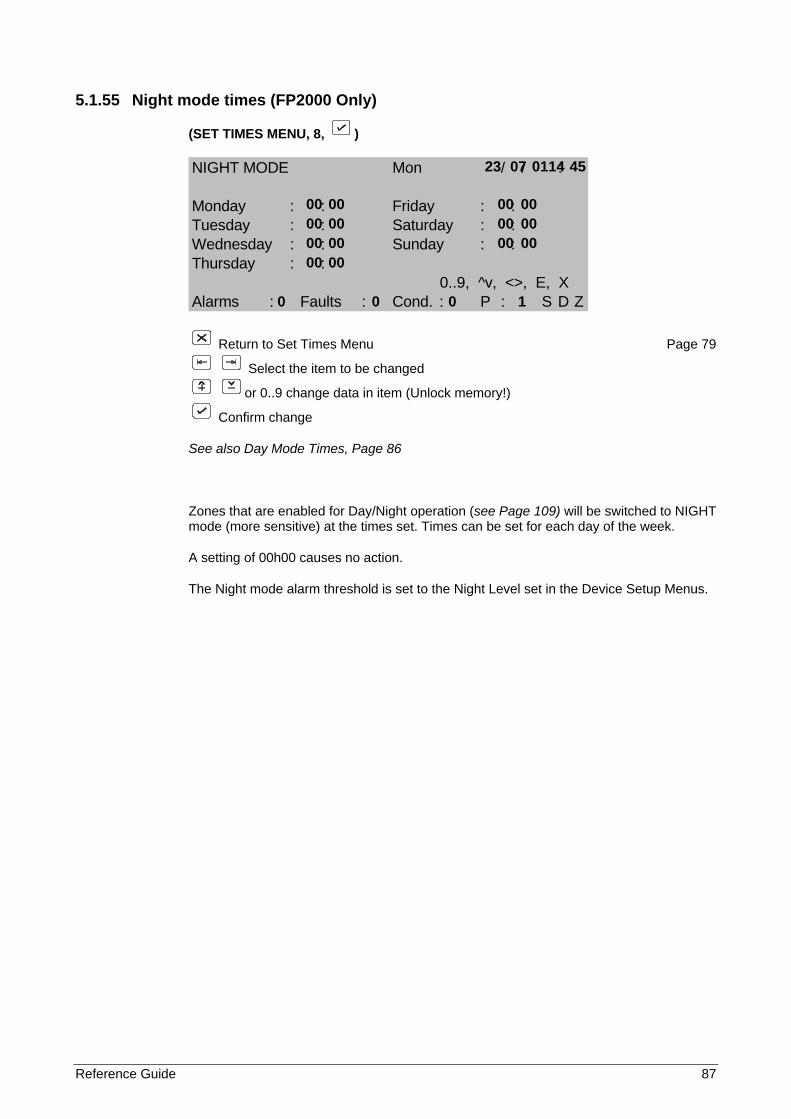
Reference Guide 87
5.1.55 Night mode times (FP2000 Only)
(SET TIMES MENU, 8, )
NIGHT MODE Mon / / :
Monday : : Friday : :Tuesday : : Saturday : :Wednesday : : Sunday : :Thursday : :
0..9, ^v, <>, E, XAlarms : Faults : Cond. : P : S D Z
Return to Set Times Menu Page 79
Select the item to be changed
or 0..9 change data in item (Unlock memory!)
Confirm change
See also Day Mode Times, Page 86
Zones that are enabled for Day/Night operation (see Page 109) will be switched to NIGHT mode (more sensitive) at the times set. Times can be set for each day of the week.
A setting of 00h00 causes no action.
The Night mode alarm threshold is set to the Night Level set in the Device Setup Menus.
23 07 01 14 45 00 00 00 00 00 00 00 00 00 00 00 00 00 00 0 0 0 1
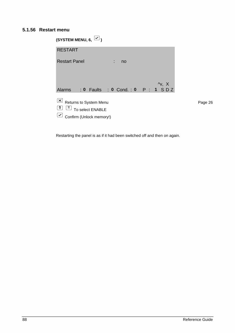
88 Reference Guide
5.1.56 Restart menu
(SYSTEM MENU, 6, )
RESTART
Restart Panel : no
^v, XAlarms : Faults : Cond. : P : S D Z
Returns to System Menu Page 26
To select ENABLE
Confirm (Unlock memory!)
Restarting the panel is as if it had been switched off and then on again.
0 0 0 1
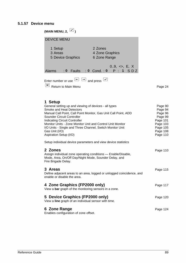
Reference Guide 89
5.1.57 Device menu
(MAIN MENU, 2, )
DEVICE MENU
1 Setup 2 Zones3 Areas 4 Zone Graphics5 Device Graphics 6 Zone Range
0..9, <>, E, XAlarms : Faults : Cond. : P : S D Z
Enter number or use and press
Return to Main Menu Page 24
1 Setup General setting up and viewing of devices - all types Page 90 Smoke and Heat Detectors Page 94 Manual Call Point, Call Point Monitor, Gas Unit Call Point, ADD Page 96 Sounder Circuit Controller Page 99 Indicating Circuit Controller Page 101 Monitor Units - Zone Monitor Unit and Control Unit Monitor Page 103 I/O Units - Single and Three Channel, Switch Monitor Unit Page 105 Gas Unit (I/O) Page 108 Aspiration Setup (I/O) Page 110
Setup individual device parameters and view device statistics
2 Zones Page 110 Assign individual zone operating conditions — Enable/Disable, Mode, Area, On/Off Day/Night Mode, Sounder Delay, and Fire Brigade Delay.
3 Areas Page 115 Define adjacent areas to an area, logged or unlogged coincidence, and enable or disable the area.
4 Zone Graphics (FP2000 only) Page 117 View a bar graph of the monitoring sensors in a zone.
5 Device Graphics (FP2000 only) Page 120 View a line graph of an individual sensor with time.
6 Zone Range Page 124 Enables configuration of zone offset.
0 0 0 1
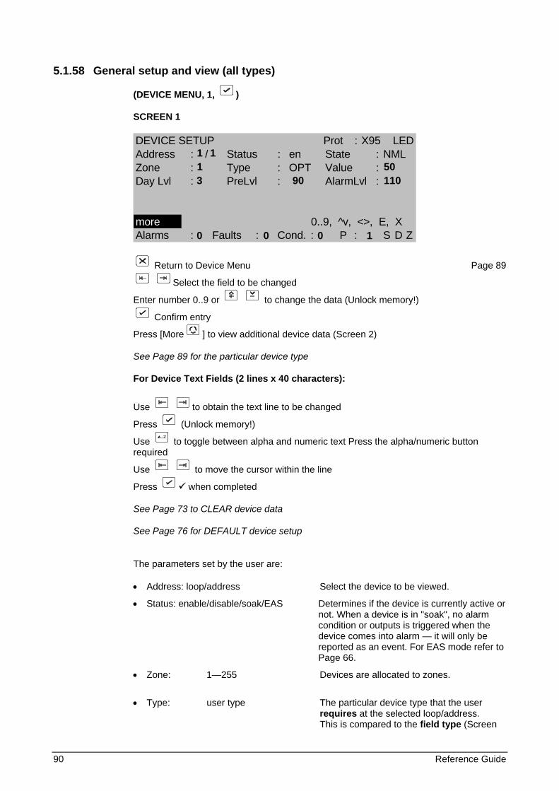
90 Reference Guide
5.1.58 General setup and view (all types)
(DEVICE MENU, 1, )
SCREEN 1
DEVICE SETUP Prot : X95 LEDAddress : / Status : en State : NMLZone : Type : OPT Value :Day Lvl : PreLvl : AlarmLvl :
more 0..9, ^v, <>, E, XAlarms : Faults : Cond. : P : S D Z
Return to Device Menu Page 89
Select the field to be changed
Enter number 0..9 or to change the data (Unlock memory!)
Confirm entry
Press [More ] to view additional device data (Screen 2)
See Page 89 for the particular device type
For Device Text Fields (2 lines x 40 characters):
Use to obtain the text line to be changed
Press (Unlock memory!)
Use to toggle between alpha and numeric text Press the alpha/numeric button required
Use to move the cursor within the line
Press when completed
See Page 73 to CLEAR device data
See Page 76 for DEFAULT device setup
The parameters set by the user are:
• Address: loop/address Select the device to be viewed.
• Status: enable/disable/soak/EAS Determines if the device is currently active or not. When a device is in "soak", no alarm condition or outputs is triggered when the device comes into alarm — it will only be reported as an event. For EAS mode refer to Page 66.
• Zone: 1—255 Devices are allocated to zones.
• Type: user type The particular device type that the user requires at the selected loop/address. This is compared to the field type (Screen
1 1 1 50
3 90 110 0 0 0 1
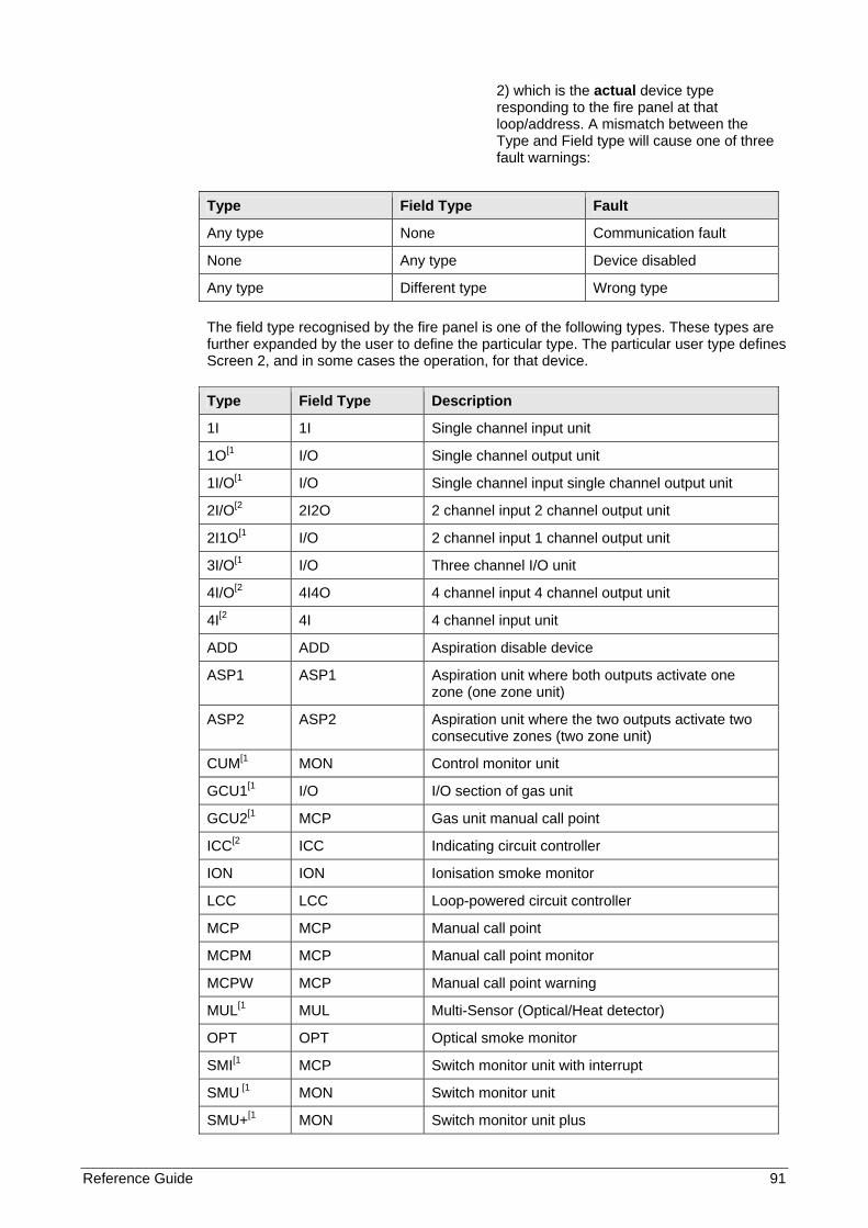
Reference Guide 91
2) which is the actual device type responding to the fire panel at that loop/address. A mismatch between the Type and Field type will cause one of three fault warnings:
Type Field Type Fault
Any type None Communication fault
None Any type Device disabled
Any type Different type Wrong type The field type recognised by the fire panel is one of the following types. These types are further expanded by the user to define the particular type. The particular user type defines Screen 2, and in some cases the operation, for that device.
Type Field Type Description
1I 1I Single channel input unit
1O[1 I/O Single channel output unit
1I/O[1 I/O Single channel input single channel output unit
2I/O[2 2I2O 2 channel input 2 channel output unit
2I1O[1 I/O 2 channel input 1 channel output unit
3I/O[1 I/O Three channel I/O unit
4I/O[2 4I4O 4 channel input 4 channel output unit
4I[2 4I 4 channel input unit
ADD ADD Aspiration disable device
ASP1 ASP1 Aspiration unit where both outputs activate one zone (one zone unit)
ASP2 ASP2 Aspiration unit where the two outputs activate two consecutive zones (two zone unit)
CUM[1 MON Control monitor unit
GCU1[1 I/O I/O section of gas unit
GCU2[1 MCP Gas unit manual call point
ICC[2 ICC Indicating circuit controller
ION ION Ionisation smoke monitor
LCC LCC Loop-powered circuit controller
MCP MCP Manual call point
MCPM MCP Manual call point monitor
MCPW MCP Manual call point warning
MUL[1 MUL Multi-Sensor (Optical/Heat detector)
OPT OPT Optical smoke monitor
SMI[1 MCP Switch monitor unit with interrupt
SMU [1 MON Switch monitor unit
SMU+[1 MON Switch monitor unit plus
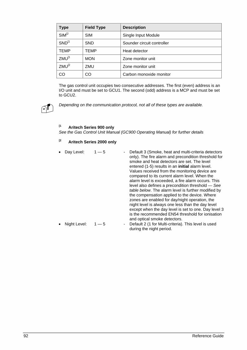
92 Reference Guide
Type Field Type Description
SIM[2 SIM Single Input Module
SND[1 SND Sounder circuit controller
TEMP TEMP Heat detector
ZMU[1 MON Zone monitor unit
ZMU[2 ZMU Zone monitor unit
CO CO Carbon monoxide monitor The gas control unit occupies two consecutive addresses. The first (even) address is an I/O unit and must be set to GCU1. The second (odd) address is a MCP and must be set to GCU2.
Depending on the communication protocol, not all of these types are available.
[1 Aritech Series 900 only See the Gas Control Unit Manual (GC900 Operating Manual) for further details
[2 Aritech Series 2000 only
• Day Level: 1 — 5 - Default 3 (Smoke, heat and multi-criteria detectors only). The fire alarm and precondition threshold for smoke and heat detectors are set. The level entered (1-5) results in an initial alarm level. Values received from the monitoring device are compared to its current alarm level. When the alarm level is exceeded, a fire alarm occurs. This level also defines a precondition threshold — See table below. The alarm level is further modified by the compensation applied to the device. Where zones are enabled for day/night operation, the night level is always one less than the day level except when the day level is set to one. Day level 3 is the recommended EN54 threshold for ionisation and optical smoke detectors.
• Night Level: 1 — 5 - Default 2 (1 for Multi-criteria). This level is used during the night period.
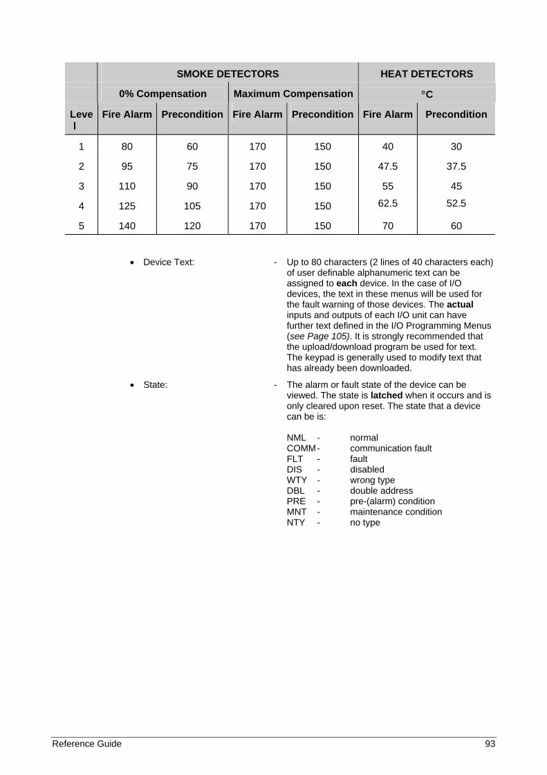
Reference Guide 93
SMOKE DETECTORS
HEAT DETECTORS
0% Compensation
Maximum Compensation
°C
Level
Fire Alarm
Precondition
Fire Alarm
Precondition
Fire Alarm
Precondition
1
80
60
170
150
40
30
2
95
75
170
150
47.5
37.5
3
110
90
170
150
55
45
4
125
105
170
150 62.5 52.5
5
140
120
170
150
70
60
• Device Text: - Up to 80 characters (2 lines of 40 characters each) of user definable alphanumeric text can be assigned to each device. In the case of I/O devices, the text in these menus will be used for the fault warning of those devices. The actual inputs and outputs of each I/O unit can have further text defined in the I/O Programming Menus (see Page 105). It is strongly recommended that the upload/download program be used for text. The keypad is generally used to modify text that has already been downloaded.
• State: - The alarm or fault state of the device can be viewed. The state is latched when it occurs and is only cleared upon reset. The state that a device can be is: NML - normal COMM - communication fault FLT - fault DIS - disabled WTY - wrong type DBL - double address PRE - pre-(alarm) condition MNT - maintenance condition NTY - no type
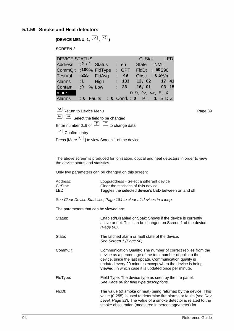
94 Reference Guide
5.1.59 Smoke and Heat detectors
(DEVICE MENU, 1, , )
SCREEN 2
DEVICE STATUS ClrStat LEDAddress : / Status : en State : NMLCommQlt : % FldType : OPT FldDt : S90TestVal : FldAvg : Obsc. : %/mAlarms : High : / :Contam. : % Low : / :more 0..9, ^v, <>, E, XAlarms : Faults : Cond. : P : S D Z
Return to Device Menu Page 89
Select the field to be changed
Enter number 0..9 or to change data
Confirm entry
Press [More ] to view Screen 1 of the device
The above screen is produced for ionisation, optical and heat detectors in order to view the device status and statistics.
Only two parameters can be changed on this screen:
Address: Loop/address - Select a different device ClrStat: Clear the statistics of this device. LED: Toggles the selected device’s LED between on and off
See Clear Device Statistics, Page 184 to clear all devices in a loop.
The parameters that can be viewed are:
Status: Enabled/Disabled or Soak: Shows if the device is currently active or not. This can be changed on Screen 1 of the device (Page 90).
State: The latched alarm or fault state of the device. See Screen 1 (Page 90)
CommQlt: Communication Quality: The number of correct replies from the device as a percentage of the total number of polls to the device, since the last update. Communication quality is updated every 20 minutes except when the device is being viewed, in which case it is updated once per minute.
FldType: Field Type: The device type as seen by the fire panel. See Page 90 for field type descriptions.
FldDt: The value (of smoke or heat) being returned by the device. This value (0-255) is used to determine fire alarms or faults (see Day Level, Page 92). The value of a smoke detector is related to the smoke obscuration (measured in percentage/meter) for
2 1 100 50 255 49 0.5 1 133 12 02 17 41 0 23 16 01 03 15
0 0 0 1
Reference Guide 95
ionisation and optical detectors, and °C for heat detectors. The protocol being used to communicate to this device is also displayed. They are:
ARI - Aritech Series 2000 DSC - Aritech Series 990 S90 - Aritech Series 900 X95 - Aritech Series 930/950/970
TestVal: The value returned during Device Self-Test. A value that is less than the alarm threshold will result in a maintenance condition.
FldAvg: The average value of the device measured over a 20-minute period.
Obsc: Percentage Obscuration (Smoke Detectors): An estimate of the smoke obscuration expressed as %/meter. This is calculated from the value returned by the device and is given for information purposes only. The fire panel uses the value for alarm and fault determination.
Temp: Temperature °C (Heat Detectors): An estimate of the heat in °C. This is calculated from the value returned by the device and is given for information purposes only. The fire panel uses the value for alarm and fault determination.
Alarms: The number of fire alarms produced by the device since the last 'Clear Statistics' operation.
High: The highest value achieved by the device and the date (dd/mm) and time (hh:mm) that this occurred.
Low: The lowest value achieved by the device and the date (dd/mm) and time (hh:mm) that this occurred.
Contam: Contamination: The amount of contamination is calculated from the long-term drift of the detector, and indicates the cleanliness of the detector. The long-term drift is generally caused by contamination, but is also affected by day/night effects especially where a zone is occupied during the day and empty at night. See Day Level, Page 92.
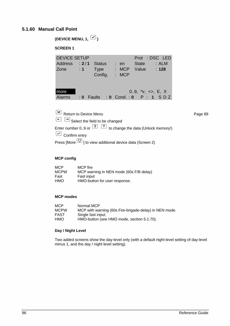
96 Reference Guide
5.1.60 Manual Call Point
(DEVICE MENU, 1, )
SCREEN 1
Return to Device Menu Page 89
Select the field to be changed
Enter number 0..9 or to change the data (Unlock memory!)
Confirm entry
Press [More ] to view additional device data (Screen 2)
MCP config
MCP MCP fire MCPW MCP warning in NEN mode (60s F/B delay) Fast Fast input HMO HMO-button for user response.
MCP modes
MCP Normal MCP MCPW MCP with warning (60s Fire-brigade-delay) in NEN mode. FAST Single fast input. HMO HMO-button (see HMO mode, section 5.1.70).
Day / Night Level
Two added screens show the day-level only (with a default night-level setting of day-level minus 1, and the day / night level setting).
DEVICE SETUP Prot : DSC LEDAddress : / Status : en State : ALMZone : Type : MCP Value :
Config. : MCP
more 0..9, ^v, <>, E, XAlarms : Faults : Cond. : P : S D Z
2 1 1 128
0 0 0 1
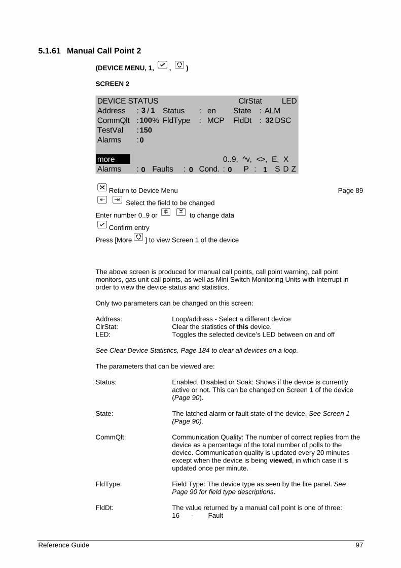
Reference Guide 97
5.1.61 Manual Call Point 2
(DEVICE MENU, 1, , )
SCREEN 2
DEVICE STATUS ClrStat LEDAddress : / Status : en State : ALMCommQlt : % FldType : MCP FldDt : DSCTestVal :Alarms :
more 0..9, ^v, <>, E, XAlarms : Faults : Cond. : P : S D Z
Return to Device Menu Page 89
Select the field to be changed
Enter number 0..9 or to change data
Confirm entry
Press [More ] to view Screen 1 of the device
The above screen is produced for manual call points, call point warning, call point monitors, gas unit call points, as well as Mini Switch Monitoring Units with Interrupt in order to view the device status and statistics.
Only two parameters can be changed on this screen:
Address: Loop/address - Select a different device ClrStat: Clear the statistics of this device. LED: Toggles the selected device’s LED between on and off
See Clear Device Statistics, Page 184 to clear all devices on a loop.
The parameters that can be viewed are:
Status: Enabled, Disabled or Soak: Shows if the device is currently active or not. This can be changed on Screen 1 of the device (Page 90).
State: The latched alarm or fault state of the device. See Screen 1 (Page 90).
CommQlt: Communication Quality: The number of correct replies from the device as a percentage of the total number of polls to the device. Communication quality is updated every 20 minutes except when the device is being viewed, in which case it is updated once per minute.
FldType: Field Type: The device type as seen by the fire panel. See Page 90 for field type descriptions.
FldDt: The value returned by a manual call point is one of three: 16 - Fault
3 1 100 32 150 0
0 0 0 1
98 Reference Guide
32 - Normal 128 - Fire Alarm
The protocol being used to communicate to this device is also displayed. They are: ARI - Aritech Series 2000
S90 - Aritech Series 900 X95 - Aritech Series 930/950/970
DSC - Aritech Series 990
TestVal: The value returned during Device Self-Test. A value that is less than the alarm threshold will result in a maintenance condition.
Alarms: The number of fire alarms produced by the device since the last 'Clear Statistics' operation.
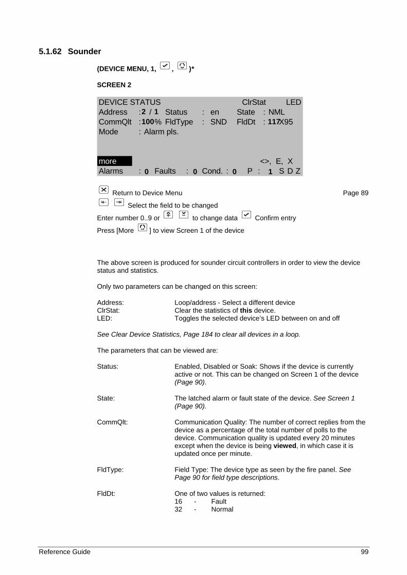
Reference Guide 99
5.1.62 Sounder
(DEVICE MENU, 1, , )*
SCREEN 2
DEVICE STATUS ClrStat LEDAddress : / Status : en State : NMLCommQlt : % FldType : SND FldDt : X95Mode : Alarm pls.
more <>, E, XAlarms : Faults : Cond. : P : S D Z
Return to Device Menu Page 89
Select the field to be changed
Enter number 0..9 or to change data Confirm entry
Press [More ] to view Screen 1 of the device
The above screen is produced for sounder circuit controllers in order to view the device status and statistics.
Only two parameters can be changed on this screen:
Address: Loop/address - Select a different device ClrStat: Clear the statistics of this device. LED: Toggles the selected device’s LED between on and off
See Clear Device Statistics, Page 184 to clear all devices in a loop.
The parameters that can be viewed are:
Status: Enabled, Disabled or Soak: Shows if the device is currently active or not. This can be changed on Screen 1 of the device (Page 90).
State: The latched alarm or fault state of the device. See Screen 1 (Page 90).
CommQlt: Communication Quality: The number of correct replies from the device as a percentage of the total number of polls to the device. Communication quality is updated every 20 minutes except when the device is being viewed, in which case it is updated once per minute.
FldType: Field Type: The device type as seen by the fire panel. See Page 90 for field type descriptions.
FldDt: One of two values is returned: 16 - Fault 32 - Normal
2 1 100 117
0 0 0 1

100 Reference Guide
The protocol being used to communicate to this device is also displayed. They are: S90 - Aritech Series 900
X95 - Aritech Series 950
Mode: The current state of the sounder. The sounder can be in one of three states: off - sounder off Warning Pls. - sounder operating intermittently Alarm Pls. - sounder operating intermittently Alarm cont. - the sounder is continuously operating
Depending on the communication protocol, this device is not always available.

Reference Guide 101
5.1.63 Indicating circuit controller
(DEVICE MENU, 1, , )*
SCREEN 2
DEVICE STATUS ClrStat LEDAddress : / Status : en State : NMLCommQlt : % FldType : ICC FldDt : ARIMode : Alarm pls.
more 0..9, ^v, <>, E, XAlarms : Faults : Cond. : P : S D Z
Return to Device Menu Page 89
Select the field to be changed
Enter number 0..9 or to change data Confirm entry
Press [More ] to view Screen 1 of the device
The above screen is produced for sounder circuit controllers in order to view the device status and statistics.
Only two parameters can be changed on this screen:
Address: Loop/address - Select a different device ClrStat: Clear the statistics of this device. LED: Toggles the selected device’s LED
See Clear Device Statistics, Page 184 to clear all devices in a loop.
The parameters that can be viewed are:
Status: Enabled, Disabled or Soak: Shows if the device is currently active or not. This can be changed on Screen 1 of the device (Page 90).
State: The latched alarm or fault state of the device. See Screen 1 (Page 90).
CommQlt: Communication Quality: The number of correct replies from the device as a percentage of the total number of polls to the device. Communication quality is updated every 20 minutes except when the device is being viewed, in which case it is updated once per minute.
FldType: Field Type: The device type as seen by the fire panel. See Page 90 for field type descriptions.
FldDt: The following values may be returned: 0 - Normal working 1 - Power up fault 2 - Supervised line open 3 - Supervised line short
2 1 100 0
0 0 0 1

102 Reference Guide
4-16 - Circuitry fault
The protocol being used to communicate to this device is also displayed. ARI - Aritech Series 2000
Mode: The current state of the sounder. The sounder can be in one of three states: off - ICC off Warning Pls. - ICC operating intermittently Alarm Pls. - ICC operating intermittently Alarm cont. - the ICC is continuously operating
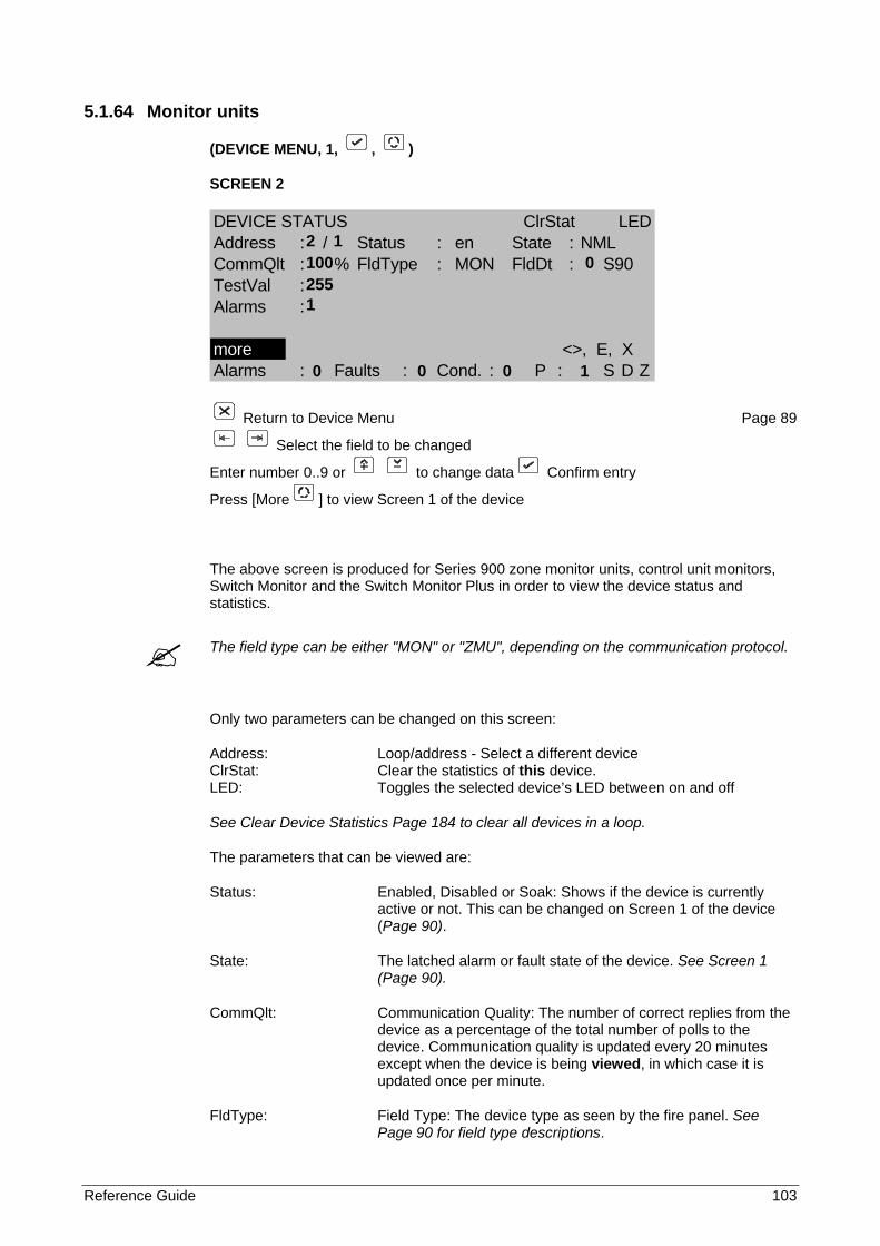
Reference Guide 103
5.1.64 Monitor units
(DEVICE MENU, 1, , )
SCREEN 2
DEVICE STATUS ClrStat LEDAddress : / Status : en State : NMLCommQlt : % FldType : MON FldDt : S90TestVal :Alarms :
more <>, E, XAlarms : Faults : Cond. : P : S D Z
Return to Device Menu Page 89
Select the field to be changed
Enter number 0..9 or to change data Confirm entry
Press [More ] to view Screen 1 of the device
The above screen is produced for Series 900 zone monitor units, control unit monitors, Switch Monitor and the Switch Monitor Plus in order to view the device status and statistics.
The field type can be either "MON" or "ZMU", depending on the communication protocol.
Only two parameters can be changed on this screen:
Address: Loop/address - Select a different device ClrStat: Clear the statistics of this device. LED: Toggles the selected device’s LED between on and off
See Clear Device Statistics Page 184 to clear all devices in a loop.
The parameters that can be viewed are:
Status: Enabled, Disabled or Soak: Shows if the device is currently active or not. This can be changed on Screen 1 of the device (Page 90).
State: The latched alarm or fault state of the device. See Screen 1 (Page 90).
CommQlt: Communication Quality: The number of correct replies from the device as a percentage of the total number of polls to the device. Communication quality is updated every 20 minutes except when the device is being viewed, in which case it is updated once per minute.
FldType: Field Type: The device type as seen by the fire panel. See Page 90 for field type descriptions.
2 1 100 0 255 1
0 0 0 1
104 Reference Guide
FldDt: The value returned by a manual call point is one of three: 16 - Fault 32 - Normal 128 - Fire Alarm
The protocol being used to communicate to this device is also displayed. They are: S90 - Aritech Series 900
X95 - Aritech Series 950
TestVal: The value returned during Device Self-Test. A value that is less than the alarm threshold will result in a maintenance condition.
Alarms: The number of fire alarms produced by the device since the last 'Clear Statistics' operation.
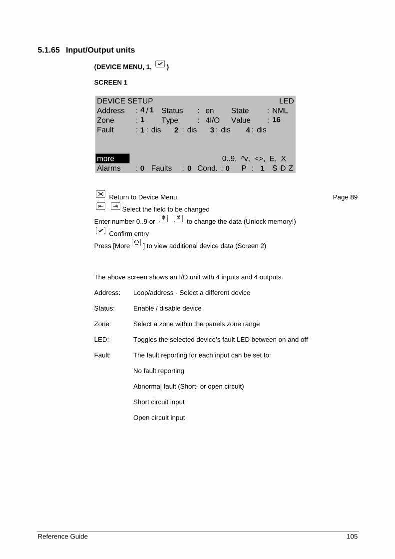
Reference Guide 105
5.1.65 Input/Output units
(DEVICE MENU, 1, )
SCREEN 1
Return to Device Menu Page 89
Select the field to be changed
Enter number 0..9 or to change the data (Unlock memory!)
Confirm entry
Press [More ] to view additional device data (Screen 2)
The above screen shows an I/O unit with 4 inputs and 4 outputs.
Address: Loop/address - Select a different device
Status: Enable / disable device
Zone: Select a zone within the panels zone range
LED: Toggles the selected device’s fault LED between on and off
Fault: The fault reporting for each input can be set to:
No fault reporting
Abnormal fault (Short- or open circuit)
Short circuit input
Open circuit input
DEVICE SETUP LEDAddress : / Status : en State : NMLZone : Type : 4I/O Value :Fault : : dis : dis : dis : dis
more 0..9, ^v, <>, E, XAlarms : Faults : Cond. : P : S D Z
4 1 1 16
1 2 3 4 0 0 0 1
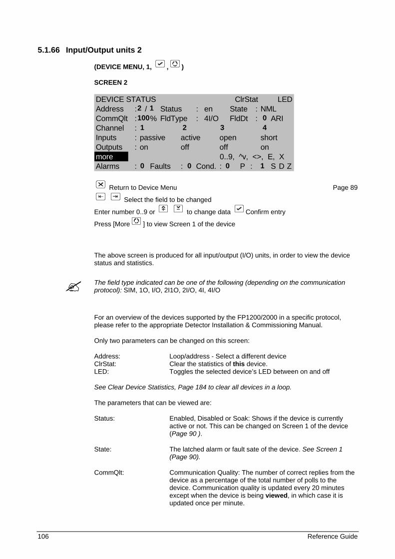
106 Reference Guide
5.1.66 Input/Output units 2
(DEVICE MENU, 1, , )
SCREEN 2
DEVICE STATUS ClrStat LEDAddress : / Status : en State : NMLCommQlt : % FldType : 4I/O FldDt : ARIChannel :Inputs : passive active open shortOutputs : on off off onmore 0..9, ^v, <>, E, XAlarms : Faults : Cond. : P : S D Z
Return to Device Menu Page 89
Select the field to be changed
Enter number 0..9 or to change data Confirm entry
Press [More ] to view Screen 1 of the device
The above screen is produced for all input/output (I/O) units, in order to view the device status and statistics.
The field type indicated can be one of the following (depending on the communication protocol): SIM, 1O, I/O, 2I1O, 2I/O, 4I, 4I/O
For an overview of the devices supported by the FP1200/2000 in a specific protocol, please refer to the appropriate Detector Installation & Commissioning Manual.
Only two parameters can be changed on this screen:
Address: Loop/address - Select a different device ClrStat: Clear the statistics of this device. LED: Toggles the selected device’s LED between on and off
See Clear Device Statistics, Page 184 to clear all devices in a loop.
The parameters that can be viewed are:
Status: Enabled, Disabled or Soak: Shows if the device is currently active or not. This can be changed on Screen 1 of the device (Page 90 ).
State: The latched alarm or fault sate of the device. See Screen 1 (Page 90).
CommQlt: Communication Quality: The number of correct replies from the device as a percentage of the total number of polls to the device. Communication quality is updated every 20 minutes except when the device is being viewed, in which case it is updated once per minute.
2 1 100 0 1 2 3 4
0 0 0 1
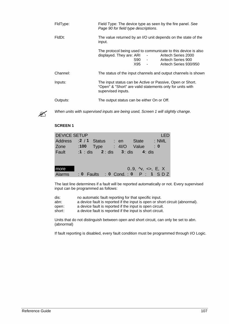
Reference Guide 107
FldType: Field Type: The device type as seen by the fire panel. See Page 90 for field type descriptions.
FldDt: The value returned by an I/O unit depends on the state of the input.
The protocol being used to communicate to this device is also displayed. They are: ARI - Aritech Series 2000
S90 - Aritech Series 900 X95 - Aritech Series 930/950
Channel: The status of the input channels and output channels is shown
Inputs: The input status can be Active or Passive, Open or Short. “Open" & "Short" are valid statements only for units with supervised inputs.
Outputs: The output status can be either On or Off.
When units with supervised inputs are being used, Screen 1 will slightly change.
SCREEN 1
DEVICE SETUP LEDAddress : / Status : en State : NMLZone : Type : 4I/O Value :Fault : : dis : dis : dis : dis
more 0..9, ^v, <>, E, XAlarms : Faults : Cond. : P : S D Z
The last line determines if a fault will be reported automatically or not. Every supervised input can be programmed as follows:
dis: no automatic fault reporting for that specific input. abn: a device fault is reported if the input is open or short circuit (abnormal). open : a device fault is reported if the input is open circuit. short : a device fault is reported if the input is short circuit.
Units that do not distinguish between open and short circuit, can only be set to abn. (abnormal)
If fault reporting is disabled, every fault condition must be programmed through I/O Logic.
2 1 100 0 1 2 3 4
0 0 0 1
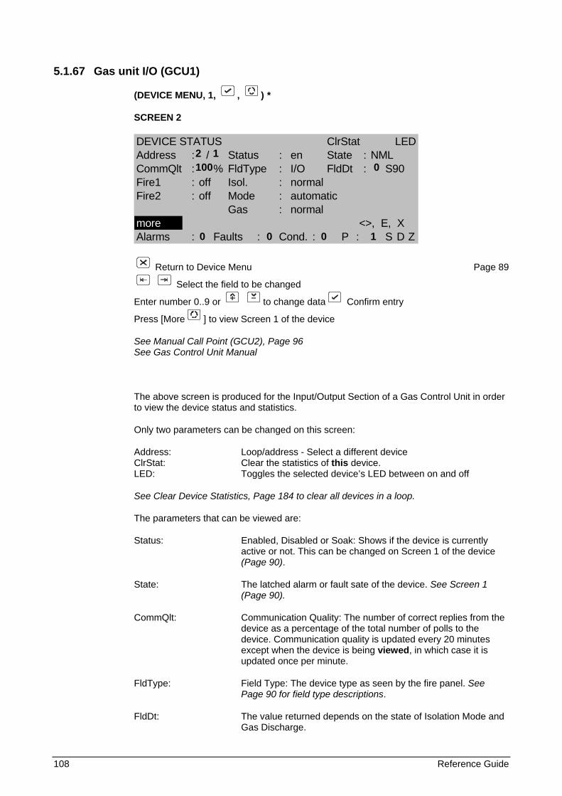
108 Reference Guide
5.1.67 Gas unit I/O (GCU1)
(DEVICE MENU, 1, , ) *
SCREEN 2
DEVICE STATUS ClrStat LEDAddress : / Status : en State : NMLCommQlt : % FldType : I/O FldDt : S90Fire1 : off Isol. : normalFire2 : off Mode : automatic
Gas : normalmore <>, E, XAlarms : Faults : Cond. : P : S D Z
Return to Device Menu Page 89
Select the field to be changed
Enter number 0..9 or to change data Confirm entry
Press [More ] to view Screen 1 of the device
See Manual Call Point (GCU2), Page 96 See Gas Control Unit Manual
The above screen is produced for the Input/Output Section of a Gas Control Unit in order to view the device status and statistics.
Only two parameters can be changed on this screen:
Address: Loop/address - Select a different device ClrStat: Clear the statistics of this device. LED: Toggles the selected device’s LED between on and off
See Clear Device Statistics, Page 184 to clear all devices in a loop.
The parameters that can be viewed are:
Status: Enabled, Disabled or Soak: Shows if the device is currently active or not. This can be changed on Screen 1 of the device (Page 90).
State: The latched alarm or fault sate of the device. See Screen 1 (Page 90).
CommQlt: Communication Quality: The number of correct replies from the device as a percentage of the total number of polls to the device. Communication quality is updated every 20 minutes except when the device is being viewed, in which case it is updated once per minute.
FldType: Field Type: The device type as seen by the fire panel. See Page 90 for field type descriptions.
FldDt: The value returned depends on the state of Isolation Mode and Gas Discharge.
2 1 100 0
0 0 0 1

Reference Guide 109
The protocol being used to communicate to this device is also displayed. This is: S90 - Aritech Series 900
The screen will also show the status of the gas control unit.
Fire 1, Fire 2 - Fire zones allocated to the unit by means of I/O programming OFF or ON
Isol - Isolated key normal or isolated
Mode - Automatic or manual
Gas - Normal or discharged
Depending on the communication protocol, this device is not always available.
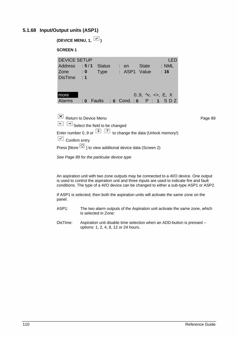
110 Reference Guide
5.1.68 Input/Output units (ASP1)
(DEVICE MENU, 1, )
SCREEN 1
Return to Device Menu Page 89
Select the field to be changed
Enter number 0..9 or to change the data (Unlock memory!)
Confirm entry
Press [More ] to view additional device data (Screen 2)
See Page 89 for the particular device type
An aspiration unit with two zone outputs may be connected to a 4I/O device. One output is used to control the aspiration unit and three inputs are used to indicate fire and fault conditions. The type of a 4I/O device can be changed to either a sub-type ASP1 or ASP2.
If ASP1 is selected, then both the aspiration units will activate the same zone on the panel. ASP1: The two alarm outputs of the Aspiration unit activate the same zone, which
is selected in Zone:
DisTime: Aspiration unit disable time selection when an ADD-button is pressed – options: 1, 2, 4, 8, 12 or 24 hours.
DEVICE SETUP LEDAddress : / Status : en State : NMLZone : Type : ASP1 Value :DisTime :
more 0..9, ^v, <>, E, XAlarms : Faults : Cond. : P : S D Z
5 1 0 16
1 0 0 0 1
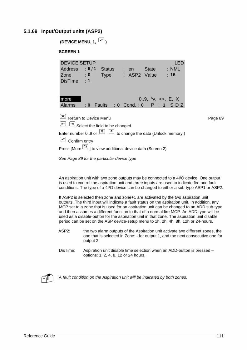
Reference Guide 111
5.1.69 Input/Output units (ASP2)
(DEVICE MENU, 1, )
SCREEN 1
Return to Device Menu Page 89
Select the field to be changed
Enter number 0..9 or to change the data (Unlock memory!)
Confirm entry
Press [More ] to view additional device data (Screen 2)
See Page 89 for the particular device type
An aspiration unit with two zone outputs may be connected to a 4I/O device. One output is used to control the aspiration unit and three inputs are used to indicate fire and fault conditions. The type of a 4I/O device can be changed to either a sub-type ASP1 or ASP2.
If ASP2 is selected then zone and zone+1 are activated by the two aspiration unit outputs. The third input will indicate a fault status on the aspiration unit. In addition, any MCP set to a zone that is used for an aspiration unit can be changed to an ADD sub-type and then assumes a different function to that of a normal fire MCP. An ADD type will be used as a disable-button for the aspiration unit in that zone. The aspiration unit disable period can be set on the ASP device-setup menu to 1h, 2h, 4h, 8h, 12h or 24-hours.
ASP2: the two alarm outputs of the Aspiration unit activate two different zones, the one that is selected in Zone: - for output 1, and the next consecutive one for output 2.
DisTime: Aspiration unit disable time selection when an ADD-button is pressed – options: 1, 2, 4, 8, 12 or 24 hours.
A fault condition on the Aspiration unit will be indicated by both zones.
DEVICE SETUP LEDAddress : / Status : en State : NMLZone : Type : ASP2 Value :DisTime :
more 0..9, ^v, <>, E, XAlarms : Faults : Cond. : P : S D Z
6 1 0 16
1 0 0 0 1
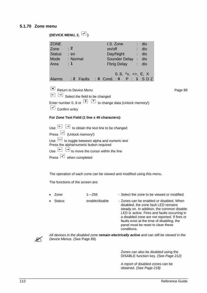
112 Reference Guide
5.1.70 Zone menu
(DEVICE MENU, 2, )
ZONE I.S. Zone : disZone : on/off : disStatus : en Day/Night : disMode : Normal Sounder Delay : disArea : Fbrig Delay : dis
0..9, ^v, <>, E, XAlarms : Faults : Cond. : P : S D Z
Return to Device Menu Page 89
Select the field to be changed
Enter number 0..9 or to change data (Unlock memory!)
Confirm entry
For Zone Text Field (1 line x 40 characters):
Use to obtain the text line to be changed
Press (Unlock memory!)
Use to toggle between alpha and numeric text Press the alpha/numeric button required
Use to move the cursor within the line
Press when completed
The operation of each zone can be viewed and modified using this menu.
The functions of the screen are:
• Zone: 1—255 - Select the zone to be viewed or modified.
• Status: enable/disable - Zones can be enabled or disabled. When disabled, the zone fault LED remains steady on. In addition, the common disable LED is active. Fires and faults occurring in a disabled zone are not reported. If fires or faults exist at the time of disabling, the panel must be reset to clear these conditions.
All devices in the disabled zone remain electrically active and can still be viewed in the Device Menus. (See Page 89).
Zones can also be disabled using the DISABLE function key. (See Page 212) A report of disabled zones can be obtained. (See Page 218)
2
1
2 0 0 1
Reference Guide 113
• Mode: - Determines the operation of a fire zone
: normal – a single device in alarm causes a fire in the zone
: confirmed – an alarm is raised only if the fire is present for more than 60s. The same applies for coincidence.
: two devices – When the first fire is detected, the panel goes into pre-alarm. A fire alarm is raised only when the second fire alarm is detected. The same applies for coincidence.
: HMO – Sets the zone to HMO functionality (See description below)
− In normal mode, a coincidence condition is logged in the event buffer when two or more fire monitoring devices of the zone are in alarm. A coincidence condition can also be used as an input for I/O logic switching. When viewing the display alarm screen, the abbreviation "COI" is displayed next to the status of devices contributing to the coincidence condition of the zone. When viewing this zone menu, the word ‘COINCIDENCE blinks if the zone currently has a coincidence condition.
• Area: 1—99 - The selected zone can be assigned to any
one of 99 areas. An area (being a group of zones) can be used for I/O switching and evacuation control. (See Page 115).
• On/Off: disable/enable - Zones that have on/off enabled are switched on and off each day according to the times set in the Set Times Menu (see Page 79). This feature is intended for security type applications (Door and I/O monitoring) and not for fire zones. Any fire monitoring device or sounder output unit that exists in a zone that is switched off in this manner, will cause a zone disablement.
• Day/Night: disable/enable - Zones that are enabled for day/night operation will switch between Day Mode and Night Mode according to the times set in the Set Times Menu (see Page 79). The devices in these zones operate at one level more sensitive during Night Mode than the level set for Day Mode. (See Page 86).
• Text: 40 chars - Each zone can have 40 characters of user text assigned. This text is used in the reporting of zone faults and conditions.
• Sounder Delay: enable/disable - Enables/disables the Sounder Delay (see Output Delays Menu and Front Panel Keys) for each individual zone. This selection must be Enabled and the front panel Sounder Delay key ON for the delay to be enabled.
• Fire Brigade Delay: enable/disable - Enables/disables the Fire Brigade Delay (see Output Delays Menu and Front Panel Keys) for each individual zone.
114 Reference Guide
This selection must be Enabled and the front panel Fire Brigade Delay key ON for the delay to be enabled.
• I.S. Zone*: enable/disable - Enables/disables an intrinsically safe zone. (The number of device LED's for this zone is limited to 2).
• Coincidence: - Indicates that two or more devices have triggered a fire alarm.
255 Zones are provided for control purposes. Depending on the configuration, 16/64 (only configuration option available for FP1200), 32/128, 48/192 or 64/255 zones can be displayed on the FP2000 front panel. It might happen that devices are allocated to zones outside the "visible" range of the fire panel, and no zone LED will illuminate when these devices go into alarm! Therefore, these zones should not be used for fire sensors, unless remote zone indicators are used.
*Depending on the communications protocol, this option is not always available.
HMO Mode:
When a block of flats has one fire panel, zones may be set to normal or HMO. Each zone that has the mode set to HMO, covers one flat only. When the zone-mode is set to HMO, all the optical-detectors, loop-sounders and an MCP that are assigned to that HMO-zone will work as follows:
A HMO zone can be in one of the following states: idle, pre-warning, vent and fire. The fire state is the normal panel fire event. A MCP in a HMO-zone can either be set up as an MCP (normal functionality) or as an HMO-button (see section 96) Setting the sub type to ”HMO” defines that the MCP has a different role.
When a sensor goes into alarm, the zone state changes to pre-alarm for 1 minute and the zone-sounders will be set to two-tone. If the HMO-button is not activated during that period, the zone will go into fire. If, on the other hand, the HMO-button is pressed before the time has elapsed, the zone changes into the vent state, which lasts for 2 minutes, and the detectors are disabled during that period. After the time has elapsed, the cycle counter is incremented, the zone state changes to idle again and the detectors are enabled again. The described cycle can be repeated three times for the same zone after which the zone state changes from idle directly into fire. If less then four cycles occur in a 20-minute period, everything in that zone is reset automatically.
The LED on a HMO-button indicates the pre-warning state. The HMO-button has no function during the other states. Repeated activation also has no further effect.
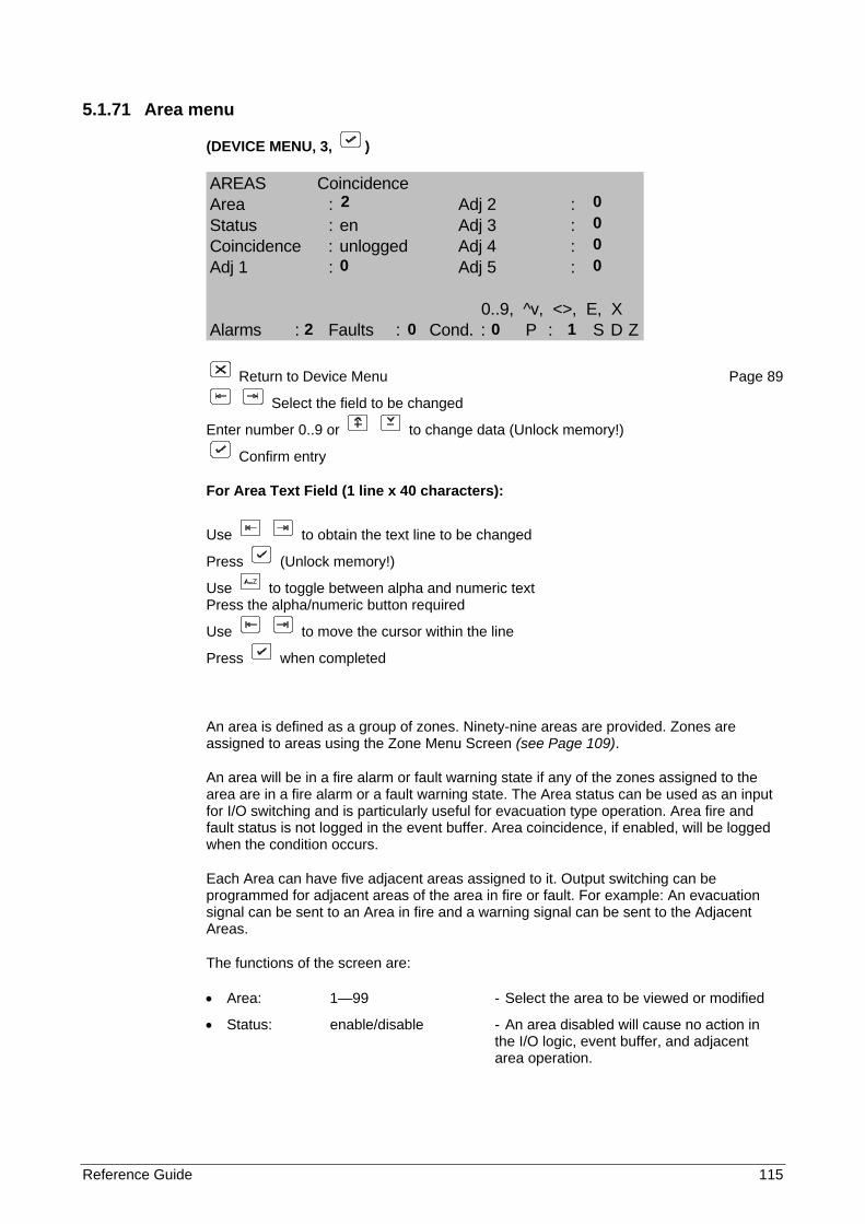
Reference Guide 115
5.1.71 Area menu
(DEVICE MENU, 3, )
AREAS CoincidenceArea : Adj 2 :Status : en Adj 3 :Coincidence : unlogged Adj 4 :Adj 1 : Adj 5 :
0..9, ^v, <>, E, XAlarms : Faults : Cond. : P : S D Z
Return to Device Menu Page 89
Select the field to be changed
Enter number 0..9 or to change data (Unlock memory!)
Confirm entry
For Area Text Field (1 line x 40 characters):
Use to obtain the text line to be changed
Press (Unlock memory!)
Use to toggle between alpha and numeric text Press the alpha/numeric button required
Use to move the cursor within the line
Press when completed
An area is defined as a group of zones. Ninety-nine areas are provided. Zones are assigned to areas using the Zone Menu Screen (see Page 109).
An area will be in a fire alarm or fault warning state if any of the zones assigned to the area are in a fire alarm or a fault warning state. The Area status can be used as an input for I/O switching and is particularly useful for evacuation type operation. Area fire and fault status is not logged in the event buffer. Area coincidence, if enabled, will be logged when the condition occurs.
Each Area can have five adjacent areas assigned to it. Output switching can be programmed for adjacent areas of the area in fire or fault. For example: An evacuation signal can be sent to an Area in fire and a warning signal can be sent to the Adjacent Areas.
The functions of the screen are:
• Area: 1—99 - Select the area to be viewed or modified
• Status: enable/disable - An area disabled will cause no action in the I/O logic, event buffer, and adjacent area operation.
2 0 0 0
0 0
2 0 0 1

116 Reference Guide
• Coincidence: logged/unlogged - Area coincidence occurs if two or more zones assigned to the area have a fire alarm. The area coincidence can be used as an input for I/O switching. When viewing this menu, the word COINCIDENCE will flash if the area is in a coincidence state. When logged, the coincidence is reported in the event buffer.
• Adj1 - Adj5: 0—99 - Up to five other areas can be defined as being adjacent to the area.
• Text: 40 Chars - Each area can have 40 characters of user text assigned. This text is used with any reports or logs generated.
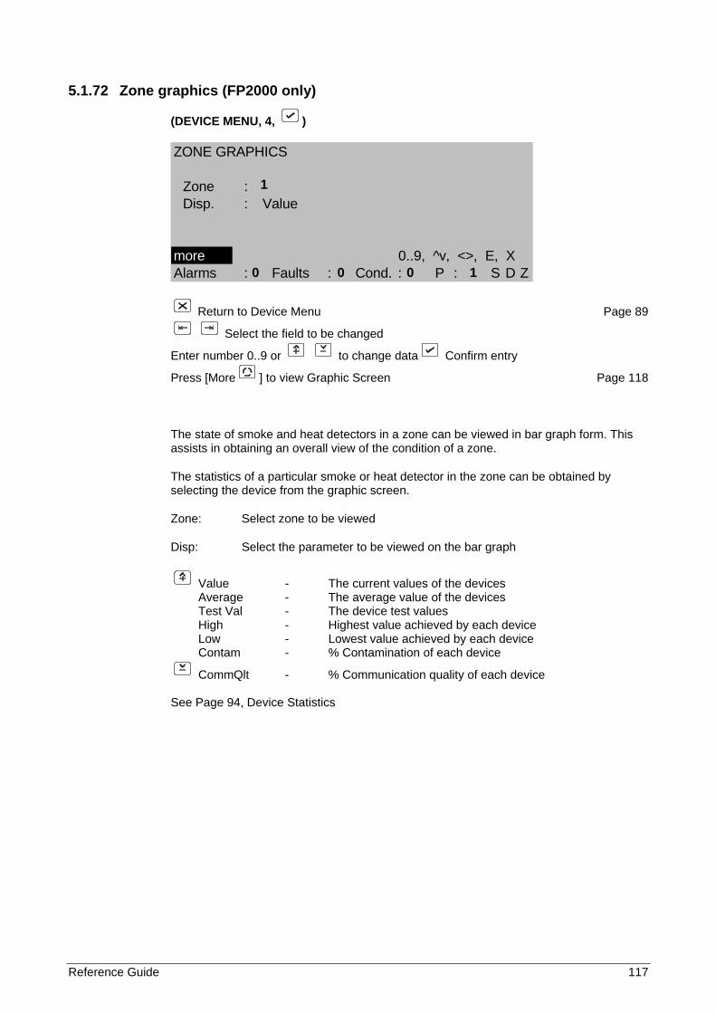
Reference Guide 117
5.1.72 Zone graphics (FP2000 only)
(DEVICE MENU, 4, )
ZONE GRAPHICS
Zone :Disp. : Value
more 0..9, ^v, <>, E, XAlarms : Faults : Cond. : P : S D Z
Return to Device Menu Page 89
Select the field to be changed
Enter number 0..9 or to change data Confirm entry
Press [More ] to view Graphic Screen Page 118
The state of smoke and heat detectors in a zone can be viewed in bar graph form. This assists in obtaining an overall view of the condition of a zone.
The statistics of a particular smoke or heat detector in the zone can be obtained by selecting the device from the graphic screen.
Zone: Select zone to be viewed
Disp: Select the parameter to be viewed on the bar graph
Value - The current values of the devices Average - The average value of the devices Test Val - The device test values High - Highest value achieved by each device Low - Lowest value achieved by each device Contam - % Contamination of each device
CommQlt - % Communication quality of each device
See Page 94, Device Statistics
1
0 0 0 1
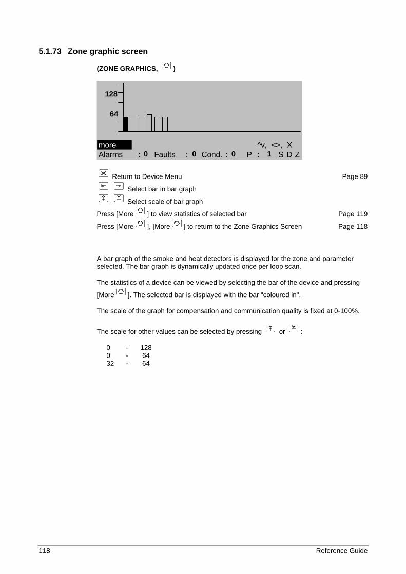
118 Reference Guide
5.1.73 Zone graphic screen
(ZONE GRAPHICS, )
more ^v, <>, XAlarms : Faults : Cond. : P : S D Z
Return to Device Menu Page 89
Select bar in bar graph
Select scale of bar graph
Press [More ] to view statistics of selected bar Page 119
Press [More ], [More ] to return to the Zone Graphics Screen Page 118
A bar graph of the smoke and heat detectors is displayed for the zone and parameter selected. The bar graph is dynamically updated once per loop scan.
The statistics of a device can be viewed by selecting the bar of the device and pressing
[More ]. The selected bar is displayed with the bar "coloured in".
The scale of the graph for compensation and communication quality is fixed at 0-100%.
The scale for other values can be selected by pressing or :
0 - 128 0 - 64 32 - 64
128
64
0 0 0 1
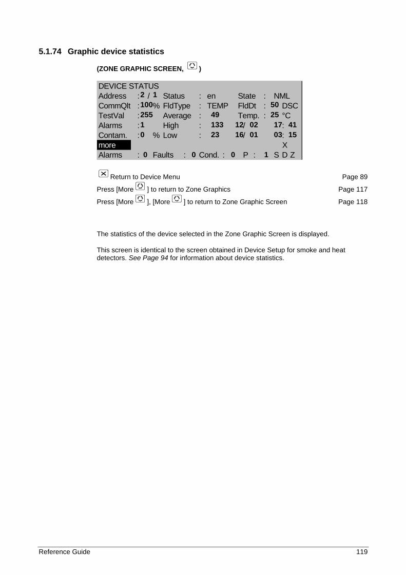
Reference Guide 119
5.1.74 Graphic device statistics
(ZONE GRAPHIC SCREEN, )
DEVICE STATUSAddress : / Status : en State : NMLCommQlt : % FldType : TEMP FldDt : DSCTestVal : Average : Temp. : °CAlarms : High : / :Contam. : % Low : / :more XAlarms : Faults : Cond. : P : S D Z
Return to Device Menu Page 89
Press [More ] to return to Zone Graphics Page 117
Press [More ], [More ] to return to Zone Graphic Screen Page 118
The statistics of the device selected in the Zone Graphic Screen is displayed.
This screen is identical to the screen obtained in Device Setup for smoke and heat detectors. See Page 94 for information about device statistics.
2 1 100 50 255 49 25 1 133 12 02 17 41 0 23 16 01 03 15
0 0 0 1
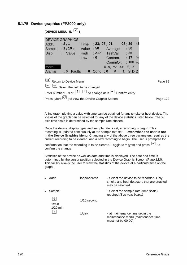
120 Reference Guide
5.1.75 Device graphics (FP2000 only)
(DEVICE MENU, 5, )
DEVICE GRAPHICSAddr. : / Time : / / : :Sample : / s Value : Average :Disp. : Value High : TestVal :
Low : Contam. : %CommQlt : %
more 0..9, ^v, <>, E, XAlarms : Faults : Cond. : P : S D Z
Return to Device Menu Page 89
Select the field to be changed
Enter number 0..9 or to change data Confirm entry
Press [More ] to view the Device Graphic Screen Page 122
A line graph plotting a value with time can be obtained for any smoke or heat device. The Y-axis of the graph can be selected for any of the device statistics listed below. The X-axis time scale is determined by the sample rate chosen.
Once the device, display type, and sample rate is set, a recording is begun. This recording is updated continuously at the sample rate set — even when the user is not in the Device Graphics Menu. Changing any of the above three parameters requires the current recording to be cleared, and a new recording to begin. The user is prompted for
confirmation that the recording is to be cleared. Toggle to Y (yes) and press to confirm the change.
Statistics of the device as well as date and time is displayed. The date and time is determined by the cursor position selected in the Device Graphic Screen (Page 122). This facility allows the user to view the statistics of the device at a particular time on the graph.
• Addr: loop/address - Select the device to be recorded. Only
smoke and heat detectors that are enabled may be selected.
• Sample: - Select the sample rate (time scale) required (See note below)
1/10 second 1/min 1/20 min
1/day - at maintenance time set in the maintenance menu (maintenance time must not be 00:00)
2 1 23 07 01 08 39 45 1 10 50 50 217 25 0 17 100
0 0 0 1
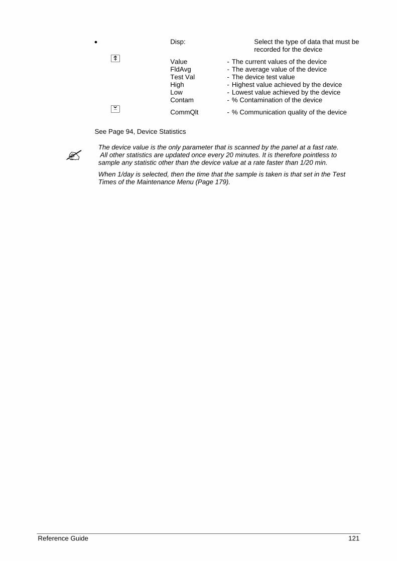
Reference Guide 121
• Disp: Select the type of data that must be recorded for the device
Value - The current values of the device FldAvg - The average value of the device Test Val - The device test value High - Highest value achieved by the device Low - Lowest value achieved by the device Contam - % Contamination of the device
CommQlt - % Communication quality of the device
See Page 94, Device Statistics
The device value is the only parameter that is scanned by the panel at a fast rate. All other statistics are updated once every 20 minutes. It is therefore pointless to sample any statistic other than the device value at a rate faster than 1/20 min.
When 1/day is selected, then the time that the sample is taken is that set in the Test Times of the Maintenance Menu (Page 179).
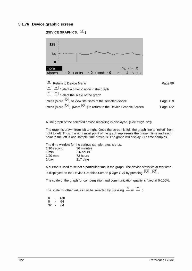
122 Reference Guide
5.1.76 Device graphic screen
(DEVICE GRAPHICS, )
more ^v, <>, XAlarms : Faults : Cond. : P : S D Z
Return to Device Menu Page 89
Select a time position in the graph
Select the scale of the graph
Press [More ] to view statistics of the selected device Page 119
Press [More ], [More ] to return to the Device Graphic Screen Page 122
A line graph of the selected device recording is displayed. (See Page 120).
The graph is drawn from left to right. Once the screen is full, the graph line is "rolled" from right to left. Thus, the right most point of the graph represents the present time and each point to the left is one sample time previous. The graph will display 217 time samples.
The time window for the various sample rates is thus: 1/10 second: 36 minutes 1/min: 3.6 hours 1/20 min: 72 hours 1/day: 217 days
A cursor is used to select a particular time in the graph. The device statistics at that time
is displayed on the Device Graphics Screen (Page 122) by pressing , .
The scale of the graph for compensation and communication quality is fixed at 0-100%.
The scale for other values can be selected by pressing or :
0 - 128 0 - 64 32 - 64
128
64 0
0 0 0 1
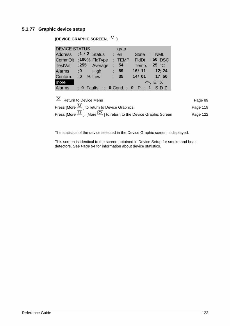
Reference Guide 123
5.1.77 Graphic device setup
(DEVICE GRAPHIC SCREEN, )
DEVICE STATUS grapAddress : / Status : en State : NMLCommQlt : % FldType : TEMP FldDt : DSCTestVal : Average : Temp. : °CAlarms : High : / :Contam. : % Low : / :more <>, E, XAlarms : Faults : Cond. : P : S D Z
Return to Device Menu Page 89
Press [More ] to return to Device Graphics Page 119
Press [More ], [More ] to return to the Device Graphic Screen Page 122
The statistics of the device selected in the Device Graphic screen is displayed.
This screen is identical to the screen obtained in Device Setup for smoke and heat detectors. See Page 94 for information about device statistics.
1 2 100 50 255 54 25 0 89 16 11 12 24 0 35 14 01 17 50
0 0 0 1
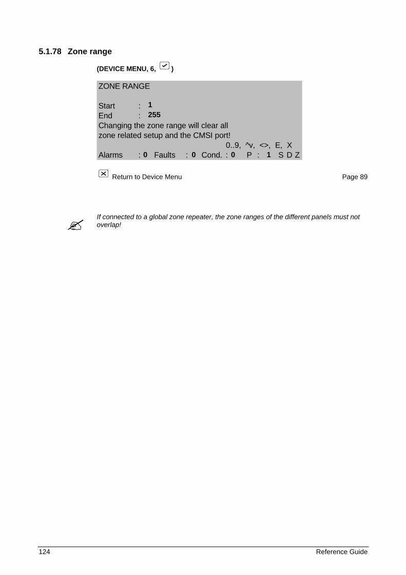
124 Reference Guide
5.1.78 Zone range
(DEVICE MENU, 6, )
ZONE RANGE
Start :End :Changing the zone range will clear allzone related setup and the CMSI port!
0..9, ^v, <>, E, XAlarms : Faults : Cond. : P : S D Z
Return to Device Menu Page 89
If connected to a global zone repeater, the zone ranges of the different panels must not overlap!
1 255
0 0 0 1
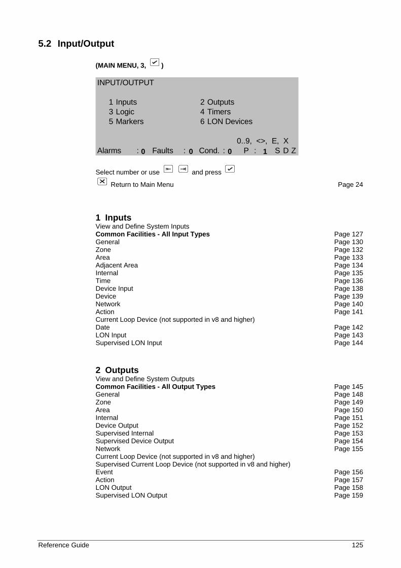
Reference Guide 125
5.2 Input/Output
(MAIN MENU, 3, )
INPUT/OUTPUT
1 Inputs 2 Outputs3 Logic 4 Timers5 Markers 6 LON Devices
0..9, <>, E, XAlarms : Faults : Cond. : P : S D Z
Select number or use and press
Return to Main Menu Page 24
1 Inputs View and Define System Inputs Common Facilities - All Input Types Page 127 General Page 130 Zone Page 132 Area Page 133 Adjacent Area Page 134 Internal Page 135 Time Page 136 Device Input Page 138 Device Page 139 Network Page 140 Action Page 141 Current Loop Device (not supported in v8 and higher) Date Page 142 LON Input Page 143 Supervised LON Input Page 144
2 Outputs View and Define System Outputs Common Facilities - All Output Types Page 145 General Page 148 Zone Page 149 Area Page 150 Internal Page 151 Device Output Page 152 Supervised Internal Page 153 Supervised Device Output Page 154 Network Page 155 Current Loop Device (not supported in v8 and higher) Supervised Current Loop Device (not supported in v8 and higher) Event Page 156 Action Page 157 LON Output Page 158 Supervised LON Output Page 159
0 0 0 1
126 Reference Guide
3 Logic View and define the logic programming that determines the switching of outputs according inputs and expressions. Page 162
4 Timers Monitoring of Timer status. Page 166
5 Markers Monitoring of Marker status. Page 167
6 LON Devices View and define the LON devices inputs and outputs. Page 168
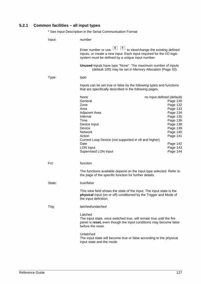
Reference Guide 127
5.2.1 Common facilities – all input types * See Input Description in the Serial Communication Format
Input: number
Enter number or use to view/change the existing defined inputs, or create a new input. Each input required for the I/O logic system must be defined by a unique input number.
Unused inputs have type "None". The maximum number of inputs (default 100) may be set in Memory Allocation (Page 33).
Type: type
Inputs can be set true or false by the following types and functions that are specifically described in the following pages.
None no input defined (default) General Page 130 Zone Page 132 Area Page 133 Adjacent Area Page 134 Internal Page 135 Time Page 136 Device Input Page 138 Device Page 139 Network Page 140 Action Page 141 Current Loop Device (not supported in v8 and higher) Date Page 142 LON Input Page 143 Supervised LON Input Page 144
Fct: function
The functions available depend on the input type selected. Refer to the page of the specific function for further details.
State: true/false
This view field shows the state of the input. The input state is the physical input (on or off) conditioned by the Trigger and Mode of the input definition.
Trig: latched/unlatched
Latched The input state, once switched true, will remain true until the fire panel is reset, even though the input conditions may become false before the reset.
Unlatched The input state will become true or false according to the physical input state and the mode.
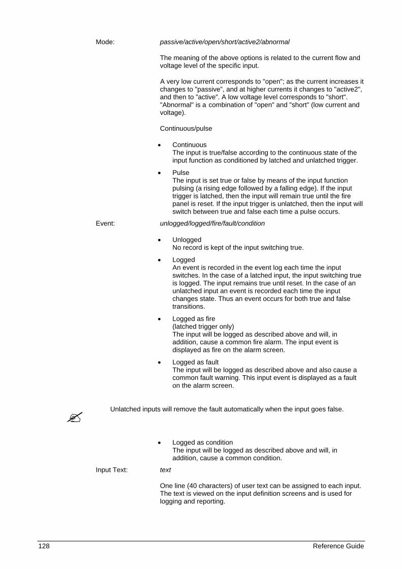
128 Reference Guide
Mode: passive/active/open/short/active2/abnormal
The meaning of the above options is related to the current flow and voltage level of the specific input.
A very low current corresponds to "open"; as the current increases it changes to "passive”, and at higher currents it changes to "active2", and then to ”active”. A low voltage level corresponds to "short". "Abnormal" is a combination of "open" and "short" (low current and voltage).
Continuous/pulse
• Continuous The input is true/false according to the continuous state of the input function as conditioned by latched and unlatched trigger.
• Pulse The input is set true or false by means of the input function pulsing (a rising edge followed by a falling edge). If the input trigger is latched, then the input will remain true until the fire panel is reset. If the input trigger is unlatched, then the input will switch between true and false each time a pulse occurs.
Event: unlogged/logged/fire/fault/condition
• Unlogged No record is kept of the input switching true.
• Logged An event is recorded in the event log each time the input switches. In the case of a latched input, the input switching true is logged. The input remains true until reset. In the case of an unlatched input an event is recorded each time the input changes state. Thus an event occurs for both true and false transitions.
• Logged as fire (latched trigger only) The input will be logged as described above and will, in addition, cause a common fire alarm. The input event is displayed as fire on the alarm screen.
• Logged as fault The input will be logged as described above and also cause a common fault warning. This input event is displayed as a fault on the alarm screen.
Unlatched inputs will remove the fault automatically when the input goes false.
• Logged as condition The input will be logged as described above and will, in addition, cause a common condition.
Input Text: text
One line (40 characters) of user text can be assigned to each input. The text is viewed on the input definition screens and is used for logging and reporting.
Reference Guide 129
Input text is only allowed for inputs that are able to use the ‘logged’ facility.
The procedure for entering text is as follows:
Use or to obtain the text line
Toggle for alpha or numeric characters
0..9 For alpha characters press key repeatedly until desired upper or lower case character or key is obtained.
Advance cursor to next position
Mover cursor back one position
Confirm end of text input
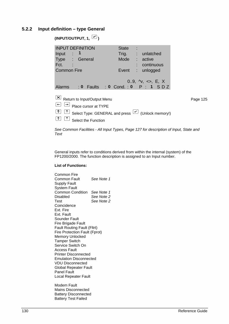
130 Reference Guide
5.2.2 Input definition – type General
(INPUT/OUTPUT, 1, )
INPUT DEFINITION State :Input : Trig. : unlatchedType : General Mode : activeFct. : : continuousCommon Fire Event : unlogged
0..9, ^v, <>, E, XAlarms : Faults : Cond. : P : S D Z
Return to Input/Output Menu Page 125
Place cursor at TYPE
Select Type: GENERAL and press (Unlock memory!)
Select the Function
See Common Facilities - All Input Types, Page 127 for description of Input, State and Text
General inputs refer to conditions derived from within the internal (system) of the FP1200/2000. The function description is assigned to an Input number.
List of Functions:
Common Fire Common Fault See Note 1 Supply Fault System Fault Common Condition See Note 1 Disabled See Note 2 Test See Note 2 Coincidence Ext. Fire Ext. Fault Sounder Fault Fire Brigade Fault Fault Routing Fault (Fltrt) Fire Protection Fault (Fprot) Memory Unlocked Tamper Switch Service Switch On Access Fault Printer Disconnected Emulation Disconnected VDU Disconnected Global Repeater Fault Panel Fault Local Repeater Fault Modem Fault Mains Disconnected Battery Disconnected Battery Test Failed
1
0 0 0 1
Reference Guide 131
Low Battery Charger Fault Earth Fault External Supply Fault Hardware Fault Sounder Disabled Fire Brigade Disabled Fault Routing Disabled Fire Protection Disabled Soak Test Zone Test Sounder Test Fire Brigade Test Fault Routing Test Fire Protection Test Maintenance BFS Disabled Pre Warning LON Device Fault
1 Common Fault/Condition is active (ON) if any Fault/Condition exists. If the originating Fault(s)/Condition(s) is/are latched, the Common Fault/Condition will be latched, if it is unlatched and is cleared before reset, the Common Fault/Condition will be cleared.
2 Common Test and Disable are manual operations and remain active until manually cleared. They are not cleared by reset.
Trigger Latched: Latched/Unlatched
Mode: Passive/Active Always continuous
Event: Always unlogged
Text: Not applicable
*See Input Description in the Serial Communication Format
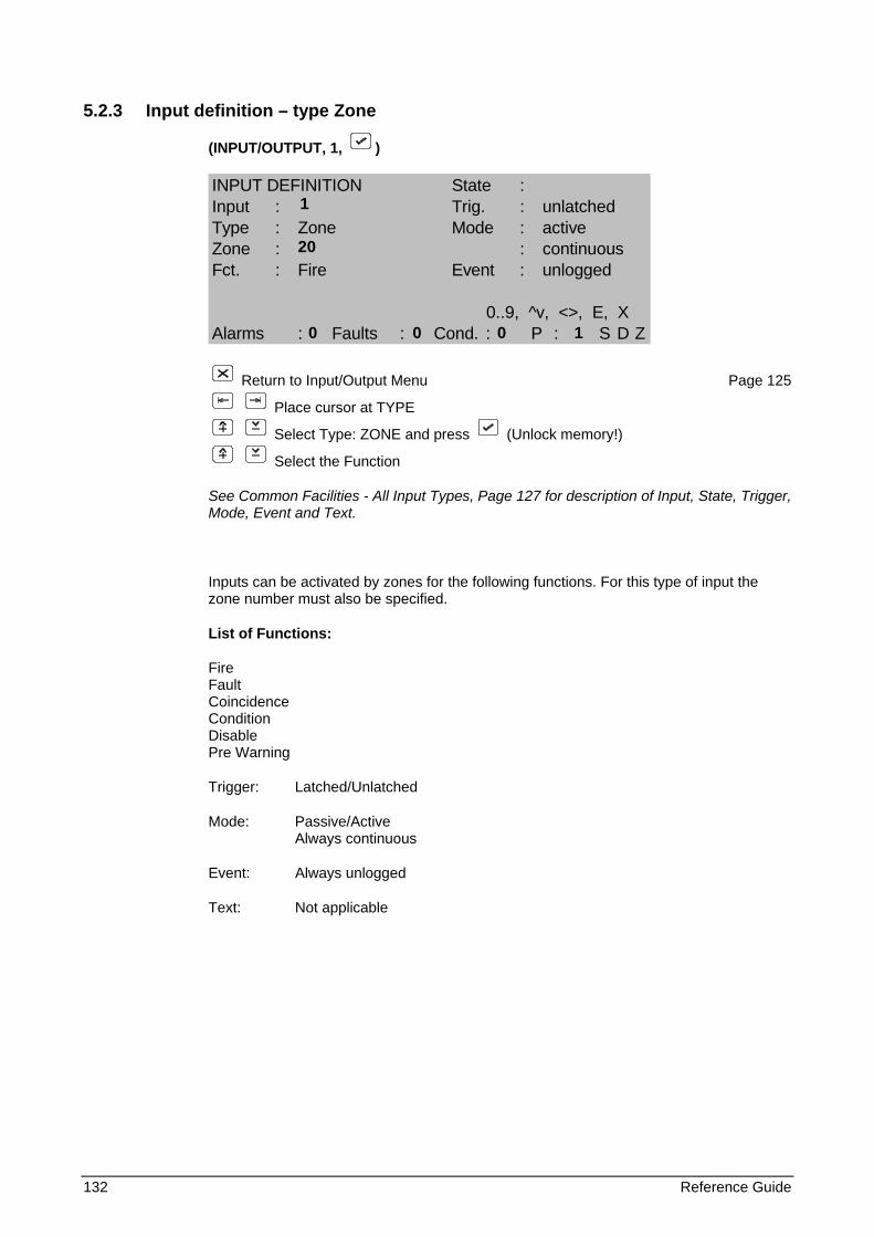
132 Reference Guide
5.2.3 Input definition – type Zone
(INPUT/OUTPUT, 1, )
INPUT DEFINITION State :Input : Trig. : unlatchedType : Zone Mode : activeZone : : continuousFct. : Fire Event : unlogged
0..9, ^v, <>, E, XAlarms : Faults : Cond. : P : S D Z
Return to Input/Output Menu Page 125
Place cursor at TYPE
Select Type: ZONE and press (Unlock memory!)
Select the Function
See Common Facilities - All Input Types, Page 127 for description of Input, State, Trigger, Mode, Event and Text.
Inputs can be activated by zones for the following functions. For this type of input the zone number must also be specified.
List of Functions:
Fire Fault Coincidence Condition Disable Pre Warning
Trigger: Latched/Unlatched
Mode: Passive/Active Always continuous
Event: Always unlogged
Text: Not applicable
1
20
0 0 0 1
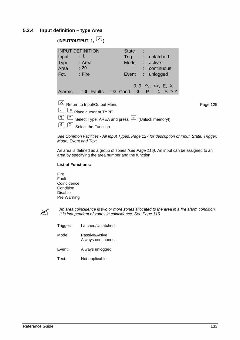
Reference Guide 133
5.2.4 Input definition – type Area
(INPUT/OUTPUT, 1, )
INPUT DEFINITION State :Input : Trig. : unlatchedType : Area Mode : activeArea : : continuousFct. : Fire Event : unlogged
0..9, ^v, <>, E, XAlarms : Faults : Cond. : P : S D Z
Return to Input/Output Menu Page 125
Place cursor at TYPE
Select Type: AREA and press (Unlock memory!)
Select the Function
See Common Facilities - All Input Types, Page 127 for description of Input, State, Trigger, Mode, Event and Text
An area is defined as a group of zones (see Page 115). An input can be assigned to an area by specifying the area number and the function.
List of Functions:
Fire Fault Coincidence Condition Disable Pre Warning
An area coincidence is two or more zones allocated to the area in a fire alarm condition. It is independent of zones in coincidence. See Page 115
Trigger: Latched/Unlatched
Mode: Passive/Active Always continuous
Event: Always unlogged
Text: Not applicable
1
20
0 0 0 1
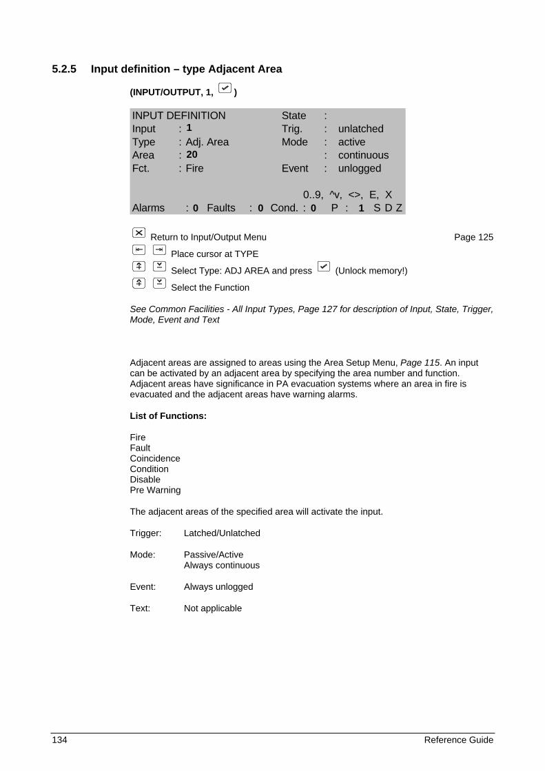
134 Reference Guide
5.2.5 Input definition – type Adjacent Area
(INPUT/OUTPUT, 1, )
INPUT DEFINITION State :Input : Trig. : unlatchedType : Adj. Area Mode : activeArea : : continuousFct. : Fire Event : unlogged
0..9, ^v, <>, E, XAlarms : Faults : Cond. : P : S D Z
Return to Input/Output Menu Page 125
Place cursor at TYPE
Select Type: ADJ AREA and press (Unlock memory!)
Select the Function
See Common Facilities - All Input Types, Page 127 for description of Input, State, Trigger, Mode, Event and Text
Adjacent areas are assigned to areas using the Area Setup Menu, Page 115. An input can be activated by an adjacent area by specifying the area number and function. Adjacent areas have significance in PA evacuation systems where an area in fire is evacuated and the adjacent areas have warning alarms.
List of Functions:
Fire Fault Coincidence Condition Disable Pre Warning
The adjacent areas of the specified area will activate the input.
Trigger: Latched/Unlatched
Mode: Passive/Active Always continuous
Event: Always unlogged
Text: Not applicable
1 20
0 0 0 1
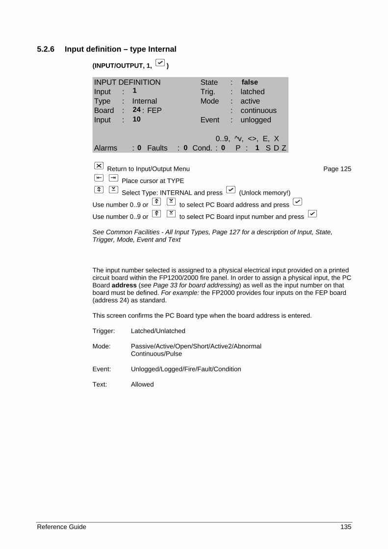
Reference Guide 135
5.2.6 Input definition – type Internal
(INPUT/OUTPUT, 1, )
INPUT DEFINITION State :Input : Trig. : latchedType : Internal Mode : activeBoard : : FEP : continuousInput : Event : unlogged
0..9, ^v, <>, E, XAlarms : Faults : Cond. : P : S D Z
Return to Input/Output Menu Page 125
Place cursor at TYPE
Select Type: INTERNAL and press (Unlock memory!)
Use number 0..9 or to select PC Board address and press
Use number 0..9 or to select PC Board input number and press
See Common Facilities - All Input Types, Page 127 for a description of Input, State, Trigger, Mode, Event and Text
The input number selected is assigned to a physical electrical input provided on a printed circuit board within the FP1200/2000 fire panel. In order to assign a physical input, the PC Board address (see Page 33 for board addressing) as well as the input number on that board must be defined. For example: the FP2000 provides four inputs on the FEP board (address 24) as standard.
This screen confirms the PC Board type when the board address is entered.
Trigger: Latched/Unlatched
Mode: Passive/Active/Open/Short/Active2/Abnormal Continuous/Pulse
Event: Unlogged/Logged/Fire/Fault/Condition
Text: Allowed
false 1
24 10
0 0 0 1
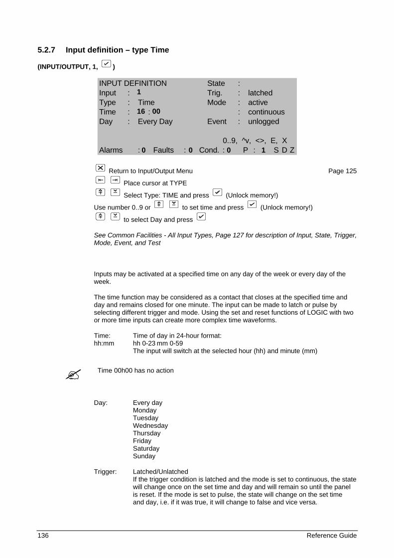
136 Reference Guide
5.2.7 Input definition – type Time
(INPUT/OUTPUT, 1, )
INPUT DEFINITION State :Input : Trig. : latchedType : Time Mode : activeTime : : : continuousDay : Every Day Event : unlogged
0..9, ^v, <>, E, XAlarms : Faults : Cond. : P : S D Z
Return to Input/Output Menu Page 125
Place cursor at TYPE
Select Type: TIME and press (Unlock memory!)
Use number 0..9 or to set time and press (Unlock memory!)
to select Day and press
See Common Facilities - All Input Types, Page 127 for description of Input, State, Trigger, Mode, Event, and Test
Inputs may be activated at a specified time on any day of the week or every day of the week.
The time function may be considered as a contact that closes at the specified time and day and remains closed for one minute. The input can be made to latch or pulse by selecting different trigger and mode. Using the set and reset functions of LOGIC with two or more time inputs can create more complex time waveforms.
Time: Time of day in 24-hour format: hh:mm hh 0-23 mm 0-59 The input will switch at the selected hour (hh) and minute (mm)
Time 00h00 has no action
Day: Every day Monday Tuesday Wednesday Thursday Friday Saturday Sunday
Trigger: Latched/Unlatched If the trigger condition is latched and the mode is set to continuous, the state will change once on the set time and day and will remain so until the panel is reset. If the mode is set to pulse, the state will change on the set time and day, i.e. if it was true, it will change to false and vice versa.
1
16 00
0 0 0 1
Reference Guide 137
If the trigger condition is unlatched, the state will change for one minute on the set day and time.
Mode: Passive/Active Continuous/Pulse
Event: Unlogged/Logged/Fire/Fault/Condition
Text: Allowed
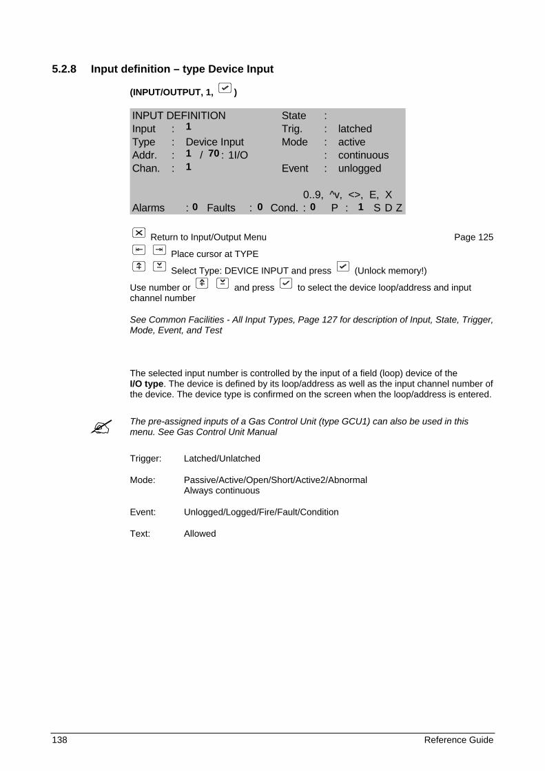
138 Reference Guide
5.2.8 Input definition – type Device Input
(INPUT/OUTPUT, 1, )
INPUT DEFINITION State :Input : Trig. : latchedType : Device Input Mode : activeAddr. : / : 1I/O : continuousChan. : Event : unlogged
0..9, ^v, <>, E, XAlarms : Faults : Cond. : P : S D Z
Return to Input/Output Menu Page 125
Place cursor at TYPE
Select Type: DEVICE INPUT and press (Unlock memory!)
Use number or and press to select the device loop/address and input channel number
See Common Facilities - All Input Types, Page 127 for description of Input, State, Trigger, Mode, Event, and Test
The selected input number is controlled by the input of a field (loop) device of the I/O type. The device is defined by its loop/address as well as the input channel number of the device. The device type is confirmed on the screen when the loop/address is entered.
The pre-assigned inputs of a Gas Control Unit (type GCU1) can also be used in this menu. See Gas Control Unit Manual
Trigger: Latched/Unlatched
Mode: Passive/Active/Open/Short/Active2/Abnormal Always continuous
Event: Unlogged/Logged/Fire/Fault/Condition
Text: Allowed
1
1 70 1
0 0 0 1
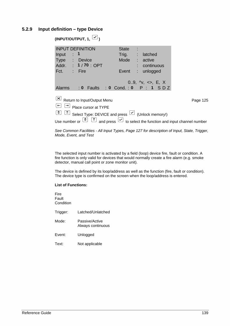
Reference Guide 139
5.2.9 Input definition – type Device
(INPUT/OUTPUT, 1, )
INPUT DEFINITION State :Input : Trig. : latchedType : Device Mode : activeAddr. : / : OPT : continuousFct. : Fire Event : unlogged
0..9, ^v, <>, E, XAlarms : Faults : Cond. : P : S D Z
Return to Input/Output Menu Page 125
Place cursor at TYPE
Select Type: DEVICE and press (Unlock memory!)
Use number or and press to select the function and input channel number
See Common Facilities - All Input Types, Page 127 for description of Input, State, Trigger, Mode, Event, and Test
The selected input number is activated by a field (loop) device fire, fault or condition. A fire function is only valid for devices that would normally create a fire alarm (e.g. smoke detector, manual call point or zone monitor unit).
The device is defined by its loop/address as well as the function (fire, fault or condition). The device type is confirmed on the screen when the loop/address is entered.
List of Functions:
Fire Fault Condition
Trigger: Latched/Unlatched
Mode: Passive/Active Always continuous
Event: Unlogged
Text: Not applicable
1 1 70
0 0 0 1
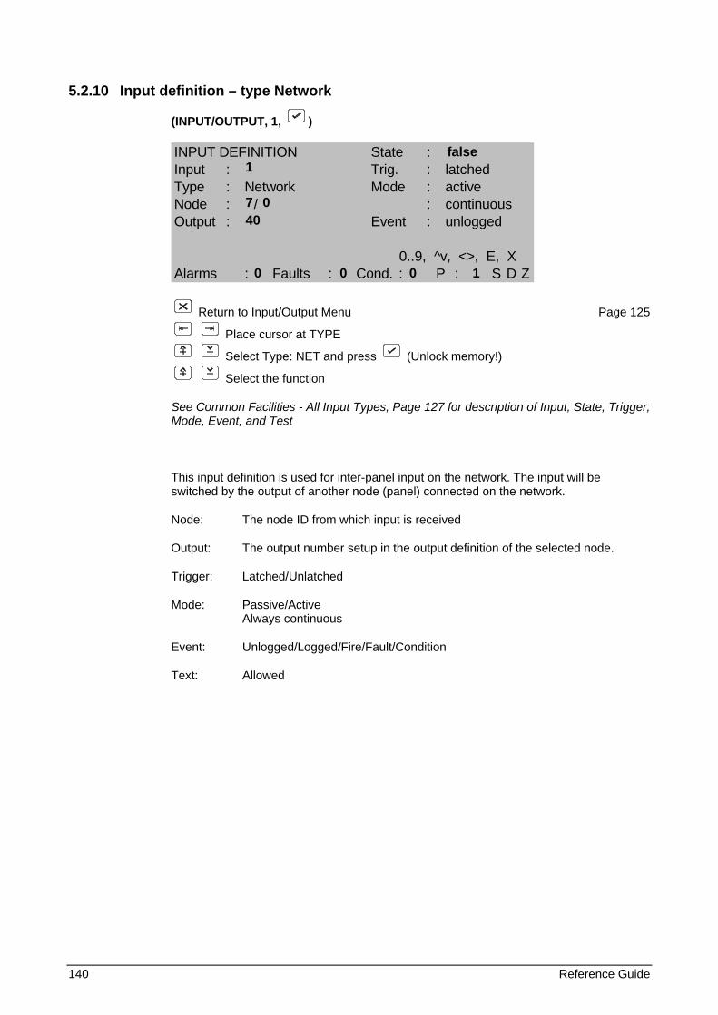
140 Reference Guide
5.2.10 Input definition – type Network
(INPUT/OUTPUT, 1, )
INPUT DEFINITION State :Input : Trig. : latchedType : Network Mode : activeNode : / : continuousOutput : Event : unlogged
0..9, ^v, <>, E, XAlarms : Faults : Cond. : P : S D Z
Return to Input/Output Menu Page 125
Place cursor at TYPE
Select Type: NET and press (Unlock memory!)
Select the function
See Common Facilities - All Input Types, Page 127 for description of Input, State, Trigger, Mode, Event, and Test
This input definition is used for inter-panel input on the network. The input will be switched by the output of another node (panel) connected on the network.
Node: The node ID from which input is received
Output: The output number setup in the output definition of the selected node.
Trigger: Latched/Unlatched
Mode: Passive/Active Always continuous
Event: Unlogged/Logged/Fire/Fault/Condition
Text: Allowed
false 1
7 0 40
0 0 0 1
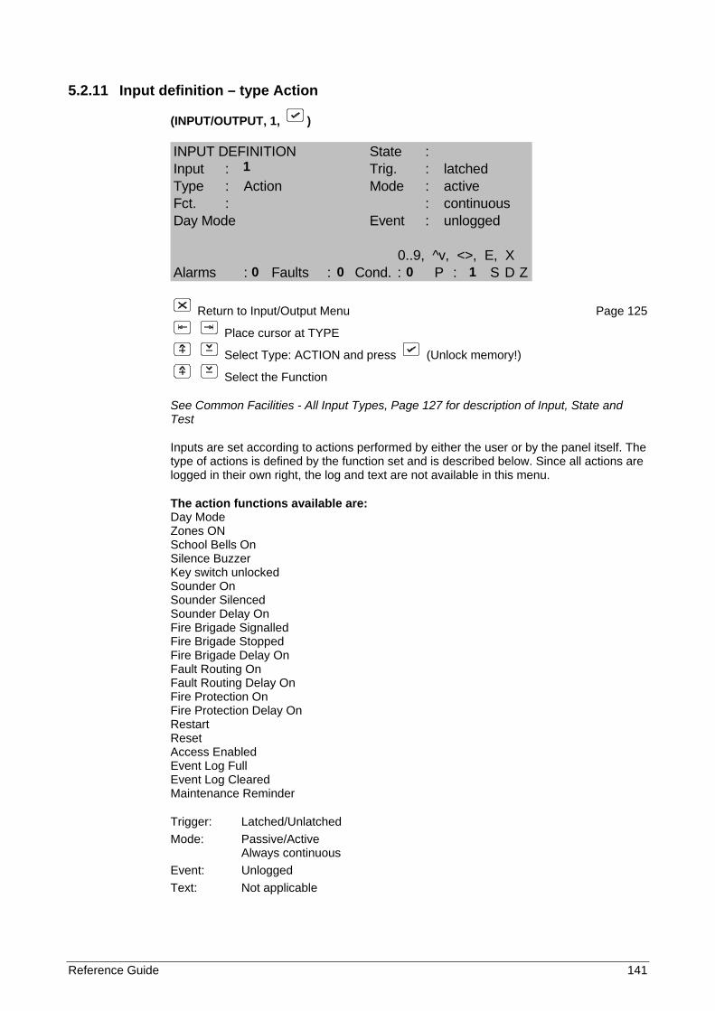
Reference Guide 141
5.2.11 Input definition – type Action
(INPUT/OUTPUT, 1, )
INPUT DEFINITION State :Input : Trig. : latchedType : Action Mode : activeFct. : : continuousDay Mode Event : unlogged
0..9, ^v, <>, E, XAlarms : Faults : Cond. : P : S D Z
Return to Input/Output Menu Page 125
Place cursor at TYPE
Select Type: ACTION and press (Unlock memory!)
Select the Function
See Common Facilities - All Input Types, Page 127 for description of Input, State and Test
Inputs are set according to actions performed by either the user or by the panel itself. The type of actions is defined by the function set and is described below. Since all actions are logged in their own right, the log and text are not available in this menu.
The action functions available are: Day Mode Zones ON School Bells On Silence Buzzer Key switch unlocked Sounder On Sounder Silenced Sounder Delay On Fire Brigade Signalled Fire Brigade Stopped Fire Brigade Delay On Fault Routing On Fault Routing Delay On Fire Protection On Fire Protection Delay On Restart Reset Access Enabled Event Log Full Event Log Cleared Maintenance Reminder
Trigger: Latched/Unlatched Mode: Passive/Active Always continuous Event: Unlogged Text: Not applicable
1
0 0 0 1
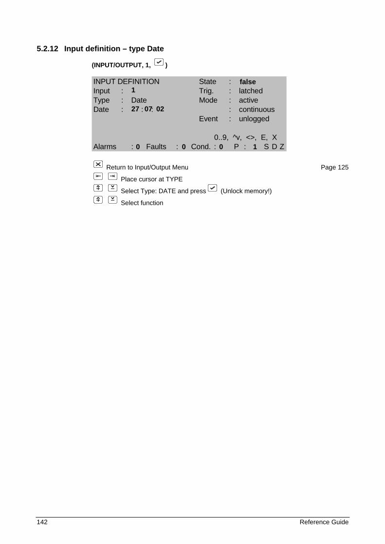
142 Reference Guide
5.2.12 Input definition – type Date
(INPUT/OUTPUT, 1, )
INPUT DEFINITION State :Input : Trig. : latchedType : Date Mode : activeDate : : : : continuous
Event : unlogged
0..9, ^v, <>, E, XAlarms : Faults : Cond. : P : S D Z
Return to Input/Output Menu Page 125
Place cursor at TYPE
Select Type: DATE and press (Unlock memory!)
Select function
false 1
27 07 02
0 0 0 1
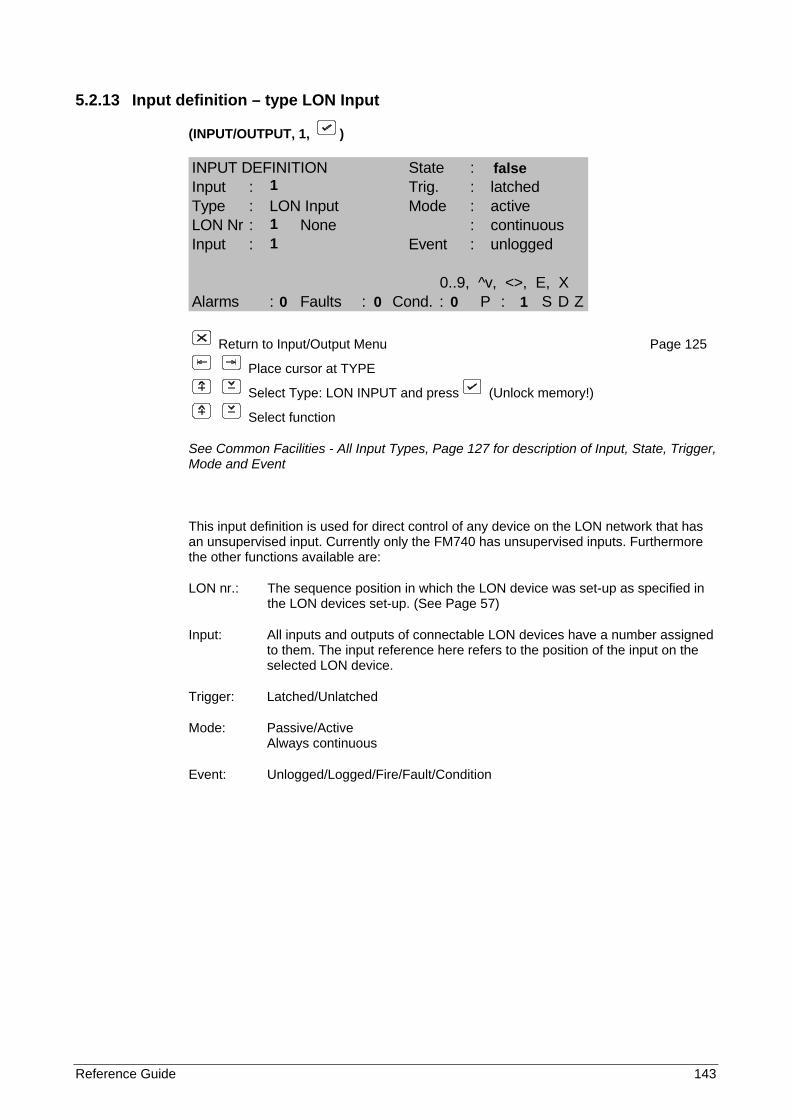
Reference Guide 143
5.2.13 Input definition – type LON Input
(INPUT/OUTPUT, 1, )
INPUT DEFINITION State :Input : Trig. : latchedType : LON Input Mode : activeLON Nr : None : continuousInput : Event : unlogged
0..9, ^v, <>, E, XAlarms : Faults : Cond. : P : S D Z
Return to Input/Output Menu Page 125
Place cursor at TYPE
Select Type: LON INPUT and press (Unlock memory!)
Select function
See Common Facilities - All Input Types, Page 127 for description of Input, State, Trigger, Mode and Event
This input definition is used for direct control of any device on the LON network that has an unsupervised input. Currently only the FM740 has unsupervised inputs. Furthermore the other functions available are:
LON nr.: The sequence position in which the LON device was set-up as specified in the LON devices set-up. (See Page 57)
Input: All inputs and outputs of connectable LON devices have a number assigned to them. The input reference here refers to the position of the input on the selected LON device.
Trigger: Latched/Unlatched
Mode: Passive/Active Always continuous
Event: Unlogged/Logged/Fire/Fault/Condition
false 1
1
1
0 0 0 1
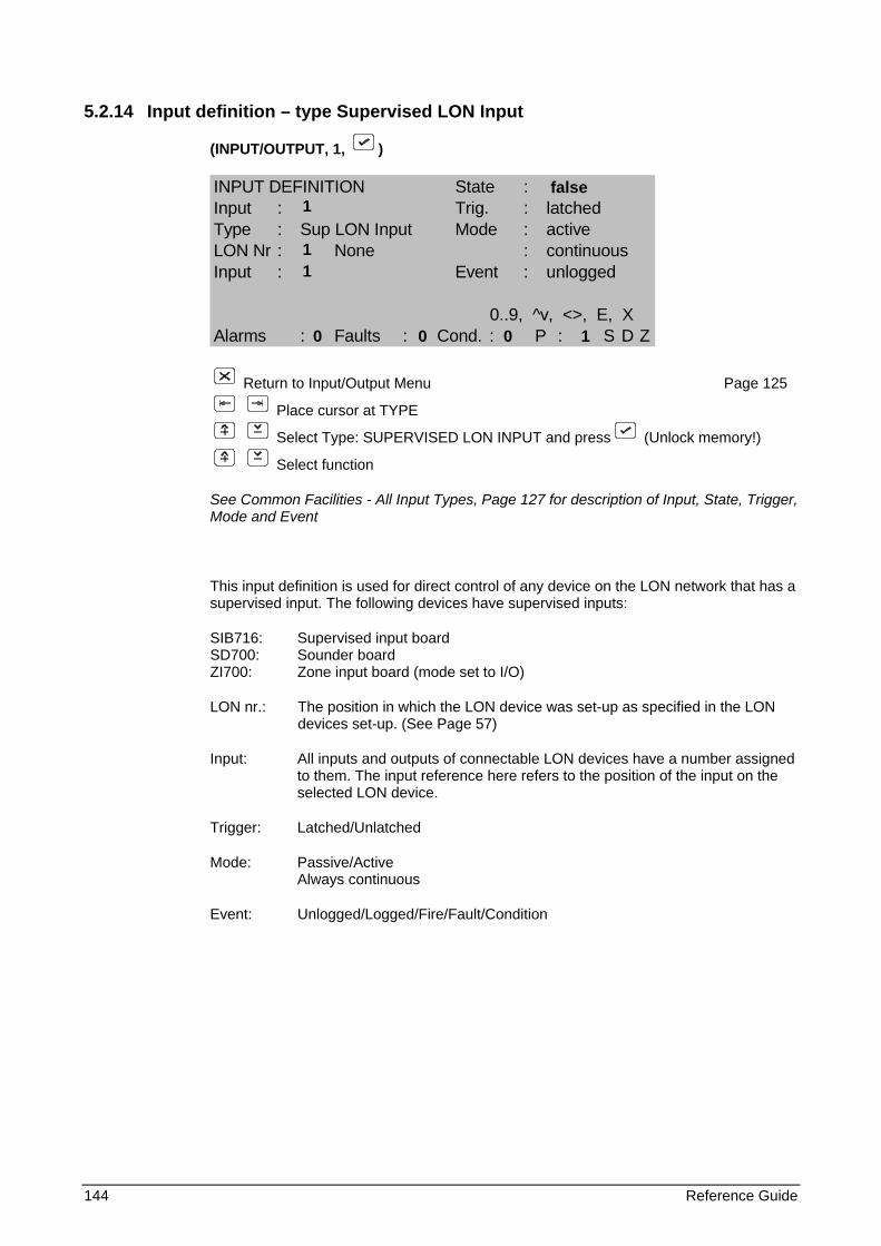
144 Reference Guide
5.2.14 Input definition – type Supervised LON Input
(INPUT/OUTPUT, 1, )
INPUT DEFINITION State :Input : Trig. : latchedType : Sup LON Input Mode : activeLON Nr : None : continuousInput : Event : unlogged
0..9, ^v, <>, E, XAlarms : Faults : Cond. : P : S D Z
Return to Input/Output Menu Page 125
Place cursor at TYPE
Select Type: SUPERVISED LON INPUT and press (Unlock memory!)
Select function
See Common Facilities - All Input Types, Page 127 for description of Input, State, Trigger, Mode and Event
This input definition is used for direct control of any device on the LON network that has a supervised input. The following devices have supervised inputs:
SIB716: Supervised input board SD700: Sounder board ZI700: Zone input board (mode set to I/O)
LON nr.: The position in which the LON device was set-up as specified in the LON devices set-up. (See Page 57)
Input: All inputs and outputs of connectable LON devices have a number assigned to them. The input reference here refers to the position of the input on the selected LON device.
Trigger: Latched/Unlatched
Mode: Passive/Active Always continuous
Event: Unlogged/Logged/Fire/Fault/Condition
false 1
1
1
0 0 0 1
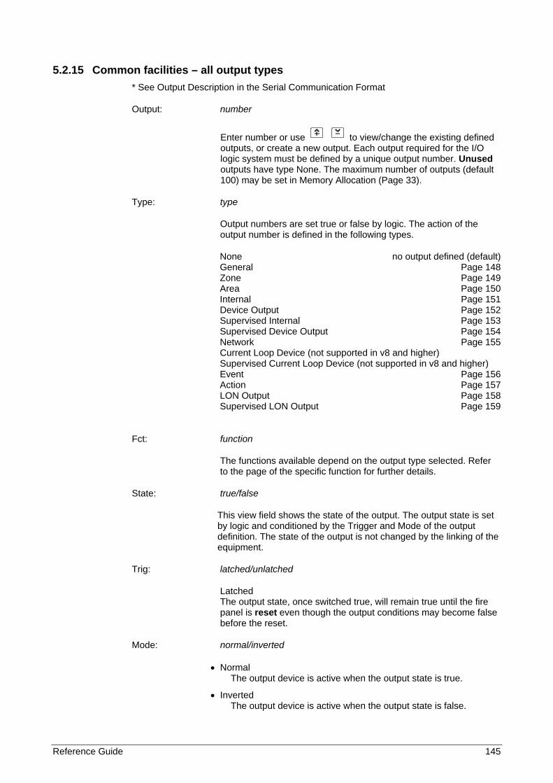
Reference Guide 145
5.2.15 Common facilities – all output types * See Output Description in the Serial Communication Format
Output: number
Enter number or use to view/change the existing defined outputs, or create a new output. Each output required for the I/O logic system must be defined by a unique output number. Unused outputs have type None. The maximum number of outputs (default 100) may be set in Memory Allocation (Page 33).
Type: type
Output numbers are set true or false by logic. The action of the output number is defined in the following types.
None no output defined (default) General Page 148 Zone Page 149 Area Page 150 Internal Page 151 Device Output Page 152 Supervised Internal Page 153 Supervised Device Output Page 154 Network Page 155 Current Loop Device (not supported in v8 and higher) Supervised Current Loop Device (not supported in v8 and higher) Event Page 156 Action Page 157 LON Output Page 158 Supervised LON Output Page 159
Fct: function
The functions available depend on the output type selected. Refer to the page of the specific function for further details.
State: true/false
This view field shows the state of the output. The output state is set by logic and conditioned by the Trigger and Mode of the output definition. The state of the output is not changed by the linking of the equipment.
Trig: latched/unlatched
Latched The output state, once switched true, will remain true until the fire panel is reset even though the output conditions may become false before the reset.
Mode: normal/inverted
• Normal The output device is active when the output state is true.
• Inverted The output device is active when the output state is false.
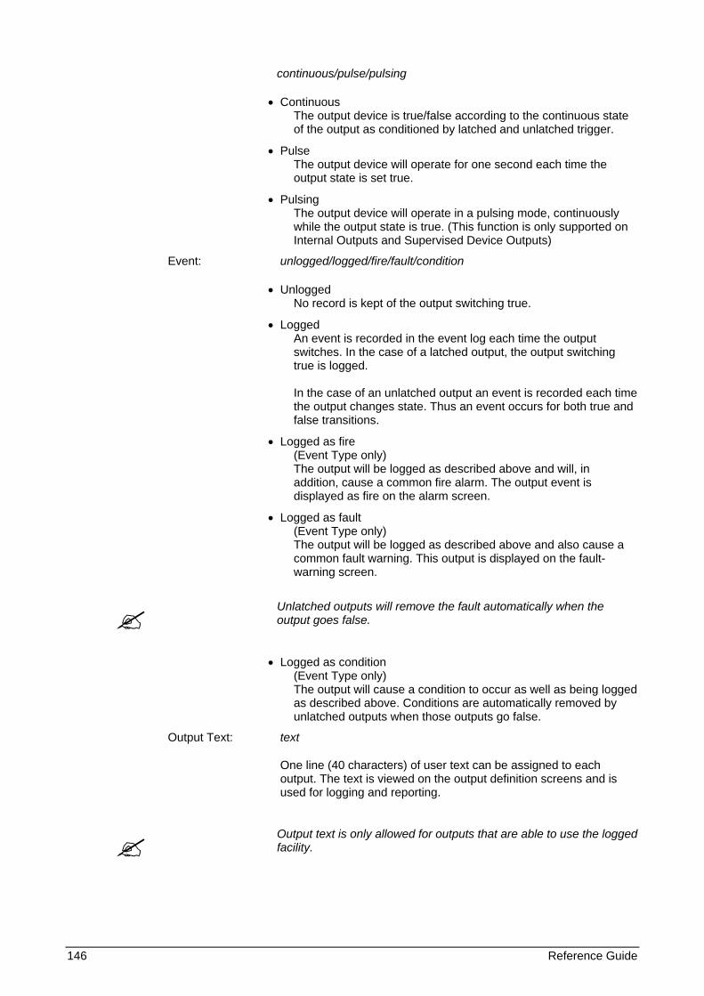
146 Reference Guide
continuous/pulse/pulsing
• Continuous The output device is true/false according to the continuous state of the output as conditioned by latched and unlatched trigger.
• Pulse The output device will operate for one second each time the output state is set true.
• Pulsing The output device will operate in a pulsing mode, continuously while the output state is true. (This function is only supported on Internal Outputs and Supervised Device Outputs)
Event: unlogged/logged/fire/fault/condition
• Unlogged No record is kept of the output switching true.
• Logged An event is recorded in the event log each time the output switches. In the case of a latched output, the output switching true is logged. In the case of an unlatched output an event is recorded each time the output changes state. Thus an event occurs for both true and false transitions.
• Logged as fire (Event Type only) The output will be logged as described above and will, in addition, cause a common fire alarm. The output event is displayed as fire on the alarm screen.
• Logged as fault (Event Type only) The output will be logged as described above and also cause a common fault warning. This output is displayed on the fault-warning screen.
Unlatched outputs will remove the fault automatically when the output goes false.
• Logged as condition
(Event Type only) The output will cause a condition to occur as well as being logged as described above. Conditions are automatically removed by unlatched outputs when those outputs go false.
Output Text: text
One line (40 characters) of user text can be assigned to each output. The text is viewed on the output definition screens and is used for logging and reporting.
Output text is only allowed for outputs that are able to use the logged facility.

Reference Guide 147
The procedure for entering text is as follows:
Use or to obtain the text line
Toggle for alpha or numeric characters
0..9 For alpha characters press key repeatedly until desired upper or lower case character or key is obtained.
Advance cursor to next position
Mover cursor back one position
Confirm end of text input
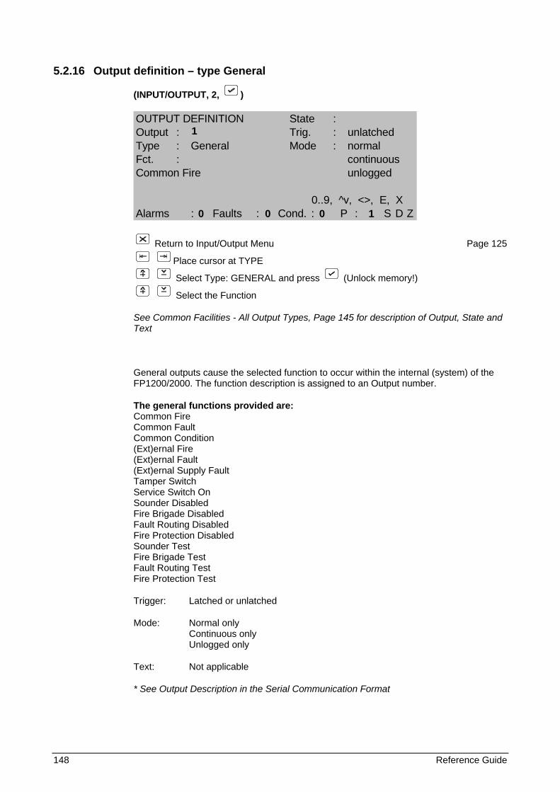
148 Reference Guide
5.2.16 Output definition – type General
(INPUT/OUTPUT, 2, )
OUTPUT DEFINITION State :Output : Trig. : unlatchedType : General Mode : normalFct. : continuousCommon Fire unlogged
0..9, ^v, <>, E, XAlarms : Faults : Cond. : P : S D Z
Return to Input/Output Menu Page 125
Place cursor at TYPE
Select Type: GENERAL and press (Unlock memory!)
Select the Function
See Common Facilities - All Output Types, Page 145 for description of Output, State and Text
General outputs cause the selected function to occur within the internal (system) of the FP1200/2000. The function description is assigned to an Output number.
The general functions provided are: Common Fire Common Fault Common Condition (Ext)ernal Fire (Ext)ernal Fault (Ext)ernal Supply Fault Tamper Switch Service Switch On Sounder Disabled Fire Brigade Disabled Fault Routing Disabled Fire Protection Disabled Sounder Test Fire Brigade Test Fault Routing Test Fire Protection Test
Trigger: Latched or unlatched
Mode: Normal only Continuous only Unlogged only
Text: Not applicable
* See Output Description in the Serial Communication Format
1
0 0 0 1
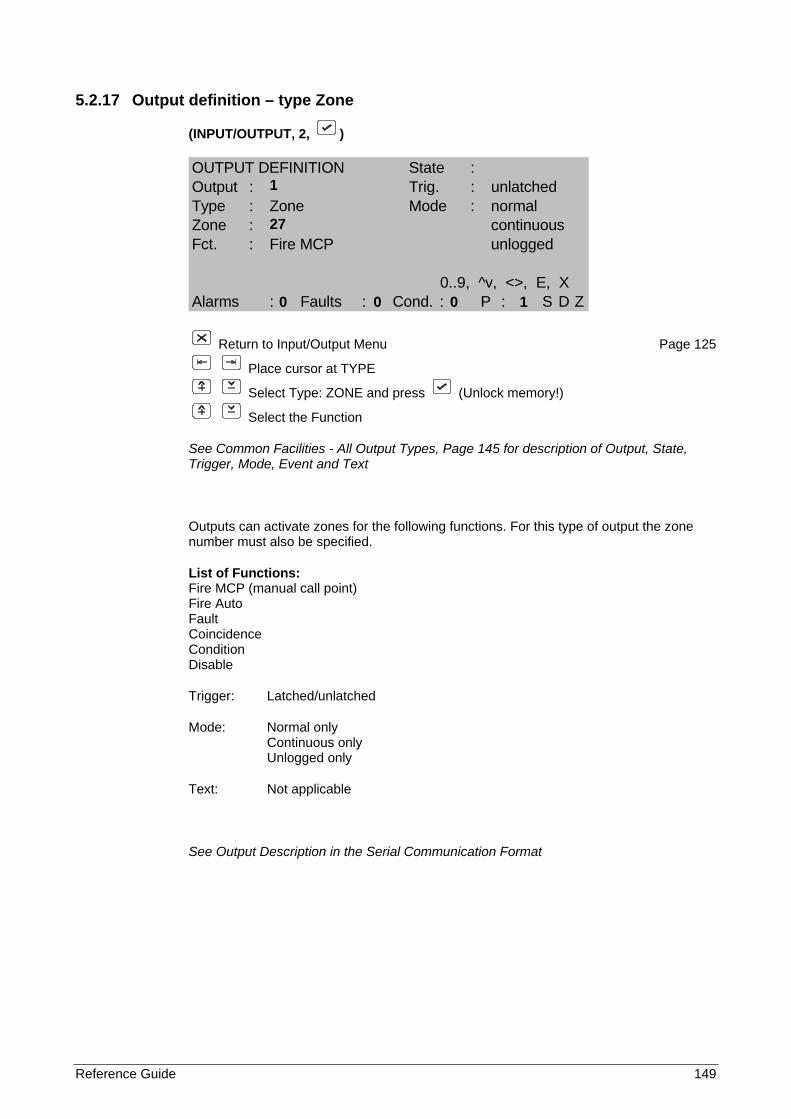
Reference Guide 149
5.2.17 Output definition – type Zone
(INPUT/OUTPUT, 2, )
OUTPUT DEFINITION State :Output : Trig. : unlatchedType : Zone Mode : normalZone : continuousFct. : Fire MCP unlogged
0..9, ^v, <>, E, XAlarms : Faults : Cond. : P : S D Z
Return to Input/Output Menu Page 125
Place cursor at TYPE
Select Type: ZONE and press (Unlock memory!)
Select the Function
See Common Facilities - All Output Types, Page 145 for description of Output, State, Trigger, Mode, Event and Text
Outputs can activate zones for the following functions. For this type of output the zone number must also be specified.
List of Functions: Fire MCP (manual call point) Fire Auto Fault Coincidence Condition Disable
Trigger: Latched/unlatched
Mode: Normal only Continuous only Unlogged only
Text: Not applicable
See Output Description in the Serial Communication Format
1
27
0 0 0 1
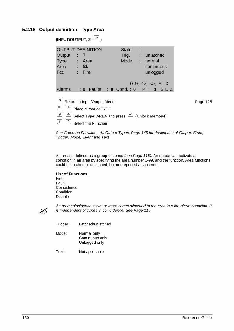
150 Reference Guide
5.2.18 Output definition – type Area
(INPUT/OUTPUT, 2, )
OUTPUT DEFINITION State :Output : Trig. : unlatchedType : Area Mode : normalArea : continuousFct. : Fire unlogged
0..9, ^v, <>, E, XAlarms : Faults : Cond. : P : S D Z
Return to Input/Output Menu Page 125
Place cursor at TYPE
Select Type: AREA and press (Unlock memory!)
Select the Function
See Common Facilities - All Output Types, Page 145 for description of Output, State, Trigger, Mode, Event and Text
An area is defined as a group of zones (see Page 115). An output can activate a condition in an area by specifying the area number 1-99, and the function. Area functions could be latched or unlatched, but not reported as an event.
List of Functions: Fire Fault Coincidence Condition Disable
An area coincidence is two or more zones allocated to the area in a fire alarm condition. It is independent of zones in coincidence. See Page 115
Trigger: Latched/unlatched
Mode: Normal only Continuous only Unlogged only
Text: Not applicable
1 51
0 0 0 1
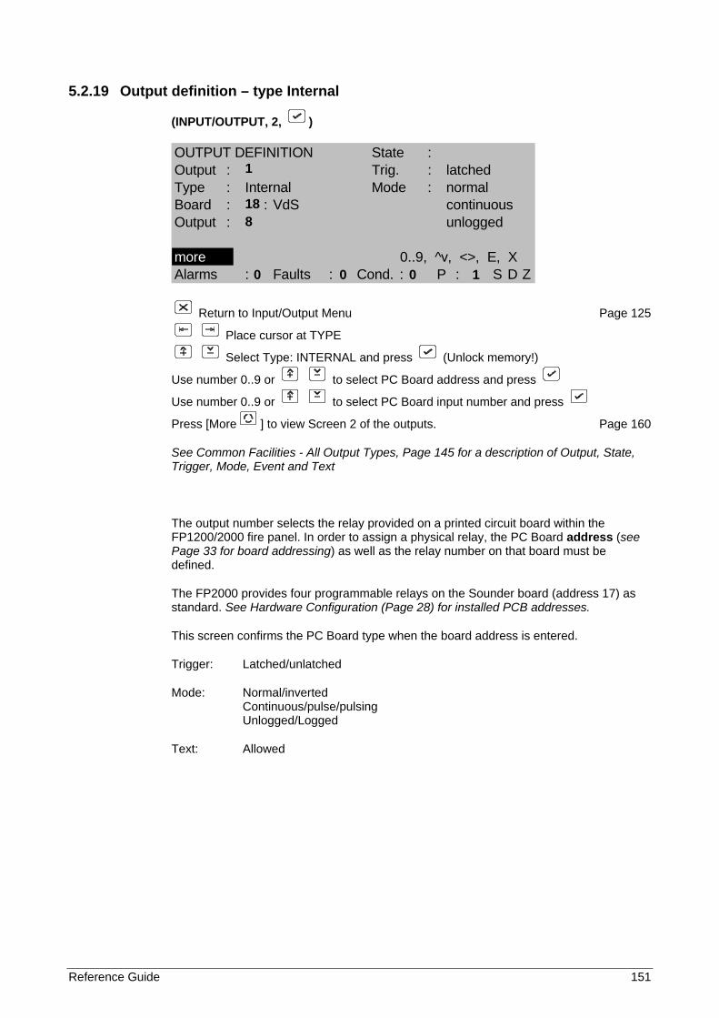
Reference Guide 151
5.2.19 Output definition – type Internal
(INPUT/OUTPUT, 2, )
OUTPUT DEFINITION State :Output : Trig. : latchedType : Internal Mode : normalBoard : : VdS continuousOutput : unlogged
more 0..9, ^v, <>, E, XAlarms : Faults : Cond. : P : S D Z
Return to Input/Output Menu Page 125
Place cursor at TYPE
Select Type: INTERNAL and press (Unlock memory!)
Use number 0..9 or to select PC Board address and press
Use number 0..9 or to select PC Board input number and press
Press [More ] to view Screen 2 of the outputs. Page 160
See Common Facilities - All Output Types, Page 145 for a description of Output, State, Trigger, Mode, Event and Text
The output number selects the relay provided on a printed circuit board within the FP1200/2000 fire panel. In order to assign a physical relay, the PC Board address (see Page 33 for board addressing) as well as the relay number on that board must be defined.
The FP2000 provides four programmable relays on the Sounder board (address 17) as standard. See Hardware Configuration (Page 28) for installed PCB addresses.
This screen confirms the PC Board type when the board address is entered.
Trigger: Latched/unlatched
Mode: Normal/inverted Continuous/pulse/pulsing Unlogged/Logged
Text: Allowed
1
18 8
0 0 0 1
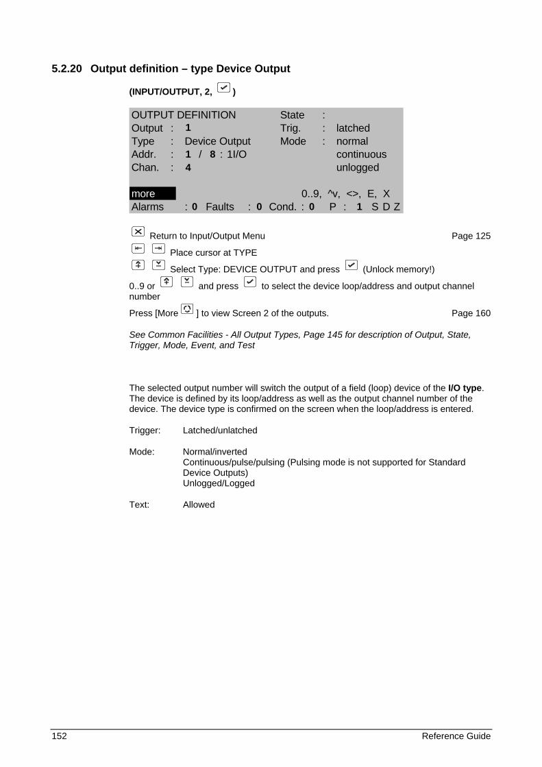
152 Reference Guide
5.2.20 Output definition – type Device Output
(INPUT/OUTPUT, 2, )
OUTPUT DEFINITION State :Output : Trig. : latchedType : Device Output Mode : normalAddr. : / : 1I/O continuousChan. : unlogged
more 0..9, ^v, <>, E, XAlarms : Faults : Cond. : P : S D Z
Return to Input/Output Menu Page 125
Place cursor at TYPE
Select Type: DEVICE OUTPUT and press (Unlock memory!)
0..9 or and press to select the device loop/address and output channel number
Press [More ] to view Screen 2 of the outputs. Page 160
See Common Facilities - All Output Types, Page 145 for description of Output, State, Trigger, Mode, Event, and Test
The selected output number will switch the output of a field (loop) device of the I/O type. The device is defined by its loop/address as well as the output channel number of the device. The device type is confirmed on the screen when the loop/address is entered.
Trigger: Latched/unlatched
Mode: Normal/inverted Continuous/pulse/pulsing (Pulsing mode is not supported for Standard Device Outputs) Unlogged/Logged
Text: Allowed
1
1 8 4
0 0 0 1
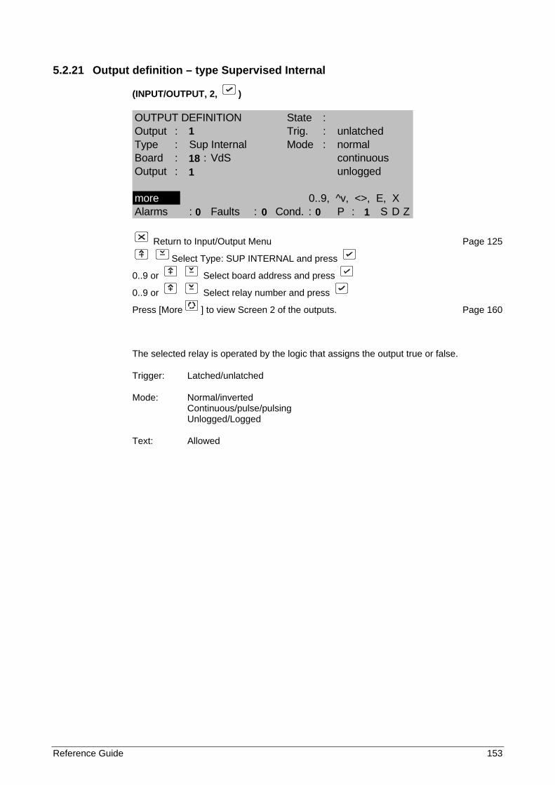
Reference Guide 153
5.2.21 Output definition – type Supervised Internal
(INPUT/OUTPUT, 2, )
OUTPUT DEFINITION State :Output : Trig. : unlatchedType : Sup Internal Mode : normalBoard : : VdS continuousOutput : unlogged
more 0..9, ^v, <>, E, XAlarms : Faults : Cond. : P : S D Z
Return to Input/Output Menu Page 125
Select Type: SUP INTERNAL and press
0..9 or Select board address and press
0..9 or Select relay number and press
Press [More ] to view Screen 2 of the outputs. Page 160
The selected relay is operated by the logic that assigns the output true or false.
Trigger: Latched/unlatched
Mode: Normal/inverted Continuous/pulse/pulsing Unlogged/Logged
Text: Allowed
1
18 1
0 0 0 1
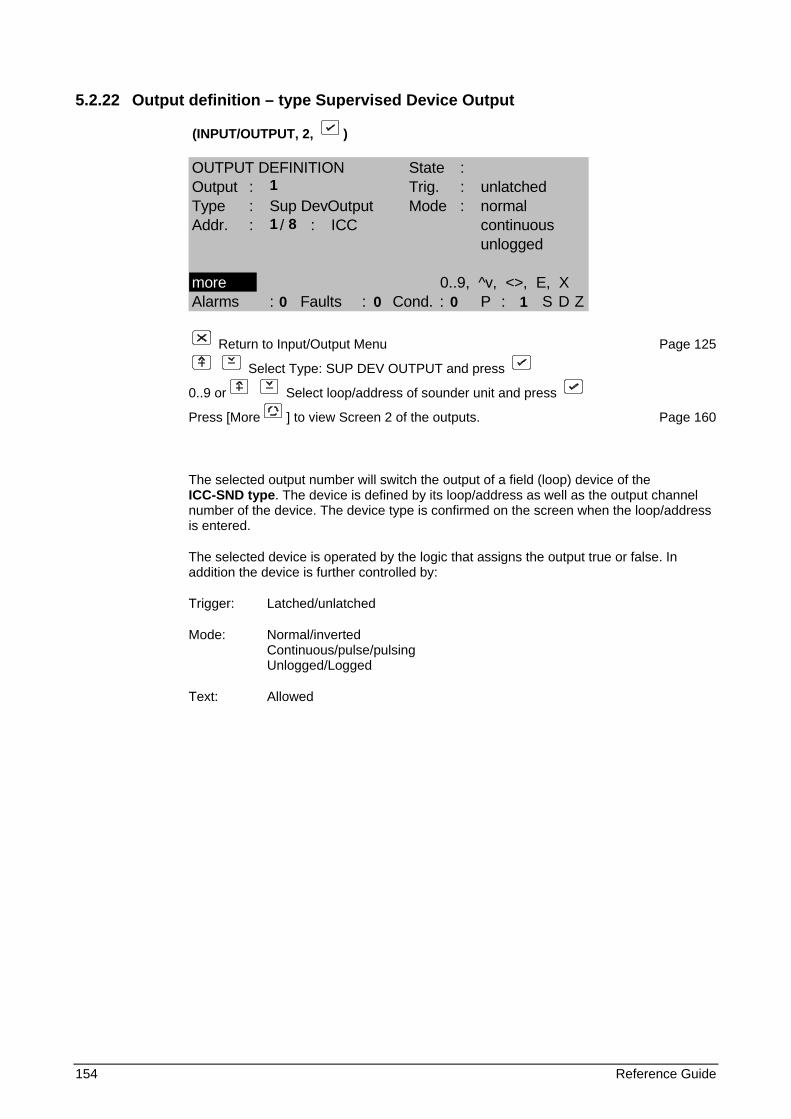
154 Reference Guide
5.2.22 Output definition – type Supervised Device Output
(INPUT/OUTPUT, 2, )
OUTPUT DEFINITION State :Output : Trig. : unlatchedType : Sup DevOutput Mode : normalAddr. : / : ICC continuous
unlogged
more 0..9, ^v, <>, E, XAlarms : Faults : Cond. : P : S D Z
Return to Input/Output Menu Page 125
Select Type: SUP DEV OUTPUT and press
0..9 or Select loop/address of sounder unit and press
Press [More ] to view Screen 2 of the outputs. Page 160
The selected output number will switch the output of a field (loop) device of the ICC-SND type. The device is defined by its loop/address as well as the output channel number of the device. The device type is confirmed on the screen when the loop/address is entered.
The selected device is operated by the logic that assigns the output true or false. In addition the device is further controlled by:
Trigger: Latched/unlatched
Mode: Normal/inverted Continuous/pulse/pulsing Unlogged/Logged
Text: Allowed
1
1 8
0 0 0 1
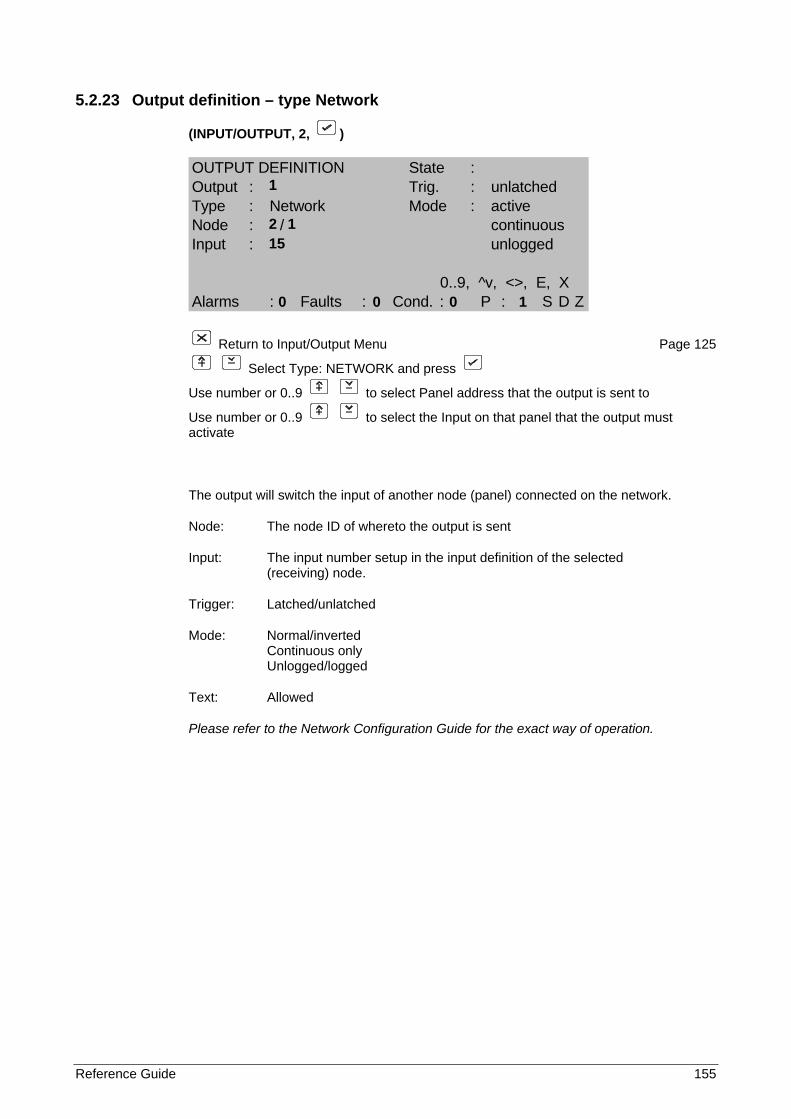
Reference Guide 155
5.2.23 Output definition – type Network
(INPUT/OUTPUT, 2, )
OUTPUT DEFINITION State :Output : Trig. : unlatchedType : Network Mode : activeNode : / continuousInput : unlogged
0..9, ^v, <>, E, XAlarms : Faults : Cond. : P : S D Z
Return to Input/Output Menu Page 125
Select Type: NETWORK and press
Use number or 0..9 to select Panel address that the output is sent to
Use number or 0..9 to select the Input on that panel that the output must activate
The output will switch the input of another node (panel) connected on the network.
Node: The node ID of whereto the output is sent
Input: The input number setup in the input definition of the selected (receiving) node.
Trigger: Latched/unlatched
Mode: Normal/inverted Continuous only Unlogged/logged
Text: Allowed
Please refer to the Network Configuration Guide for the exact way of operation.
1
2 1 15
0 0 0 1
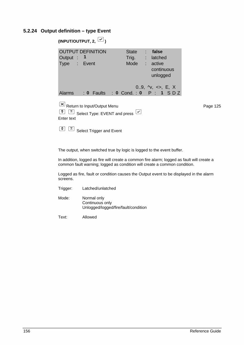
156 Reference Guide
5.2.24 Output definition – type Event
(INPUT/OUTPUT, 2, )
OUTPUT DEFINITION State :Output : Trig. : latchedType : Event Mode : active
continuousunlogged
0..9, ^v, <>, E, XAlarms : Faults : Cond. : P : S D Z
Return to Input/Output Menu Page 125
Select Type: EVENT and press Enter text
Select Trigger and Event
The output, when switched true by logic is logged to the event buffer.
In addition, logged as fire will create a common fire alarm; logged as fault will create a common fault warning; logged as condition will create a common condition.
Logged as fire, fault or condition causes the Output event to be displayed in the alarm screens.
Trigger: Latched/unlatched
Mode: Normal only Continuous only Unlogged/logged/fire/fault/condition
Text: Allowed
false 1
0 0 0 1
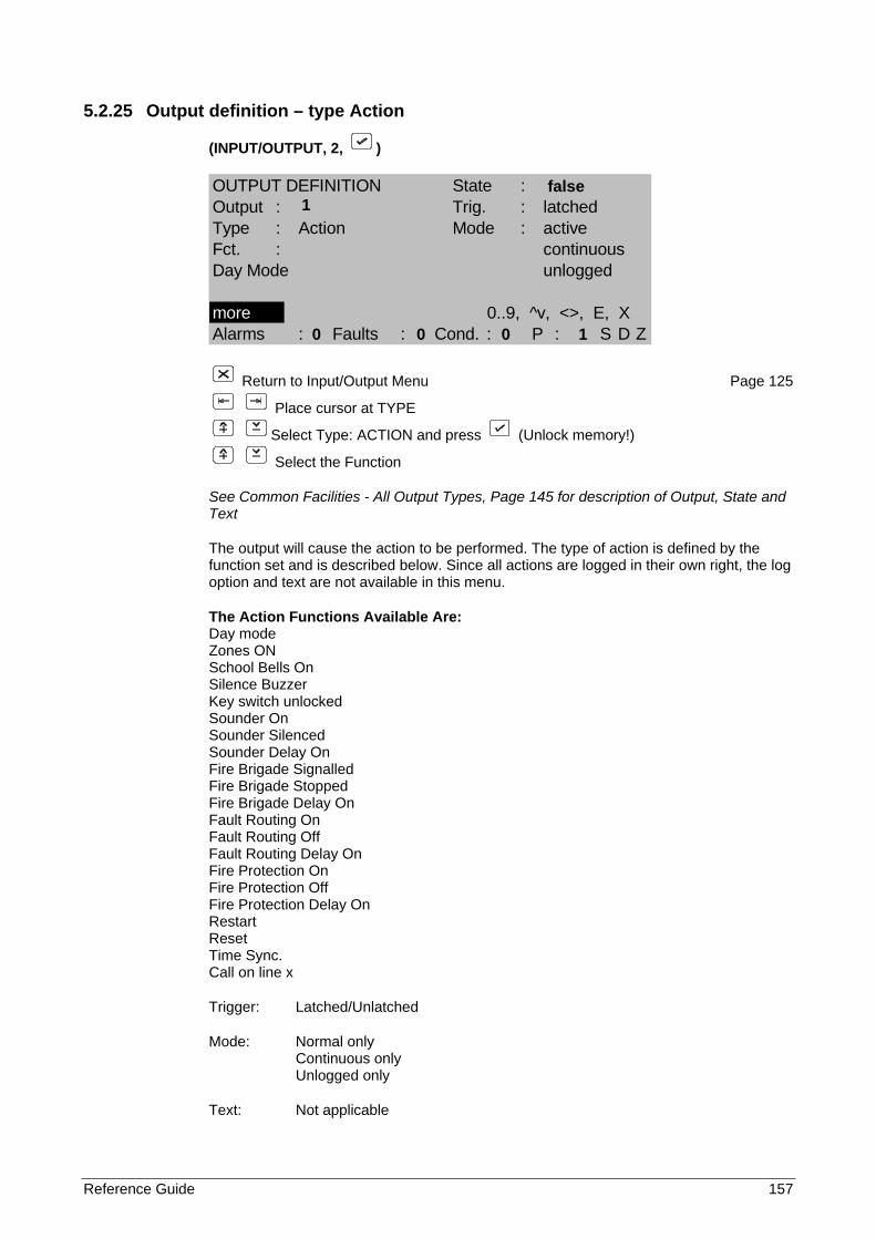
Reference Guide 157
5.2.25 Output definition – type Action
(INPUT/OUTPUT, 2, )
OUTPUT DEFINITION State :Output : Trig. : latchedType : Action Mode : activeFct. : continuousDay Mode unlogged
more 0..9, ^v, <>, E, XAlarms : Faults : Cond. : P : S D Z
Return to Input/Output Menu Page 125
Place cursor at TYPE
Select Type: ACTION and press (Unlock memory!)
Select the Function
See Common Facilities - All Output Types, Page 145 for description of Output, State and Text
The output will cause the action to be performed. The type of action is defined by the function set and is described below. Since all actions are logged in their own right, the log option and text are not available in this menu.
The Action Functions Available Are: Day mode Zones ON School Bells On Silence Buzzer Key switch unlocked Sounder On Sounder Silenced Sounder Delay On Fire Brigade Signalled Fire Brigade Stopped Fire Brigade Delay On Fault Routing On Fault Routing Off Fault Routing Delay On Fire Protection On Fire Protection Off Fire Protection Delay On Restart Reset Time Sync. Call on line x
Trigger: Latched/Unlatched
Mode: Normal only Continuous only Unlogged only
Text: Not applicable
false 1
0 0 0 1
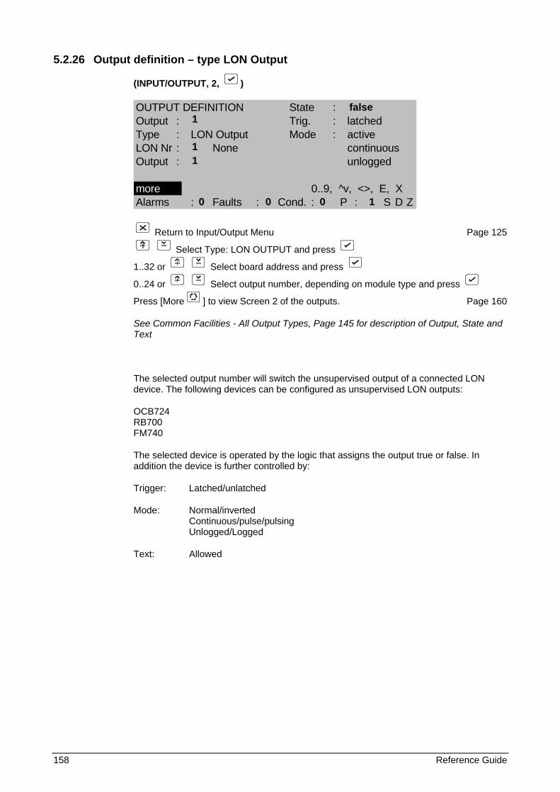
158 Reference Guide
5.2.26 Output definition – type LON Output
(INPUT/OUTPUT, 2, )
OUTPUT DEFINITION State :Output : Trig. : latchedType : LON Output Mode : activeLON Nr : None continuousOutput : unlogged
more 0..9, ^v, <>, E, XAlarms : Faults : Cond. : P : S D Z
Return to Input/Output Menu Page 125
Select Type: LON OUTPUT and press
1..32 or Select board address and press
0..24 or Select output number, depending on module type and press
Press [More ] to view Screen 2 of the outputs. Page 160
See Common Facilities - All Output Types, Page 145 for description of Output, State and Text
The selected output number will switch the unsupervised output of a connected LON device. The following devices can be configured as unsupervised LON outputs:
OCB724 RB700 FM740
The selected device is operated by the logic that assigns the output true or false. In addition the device is further controlled by:
Trigger: Latched/unlatched
Mode: Normal/inverted Continuous/pulse/pulsing Unlogged/Logged
Text: Allowed
false 1
1 1
0 0 0 1
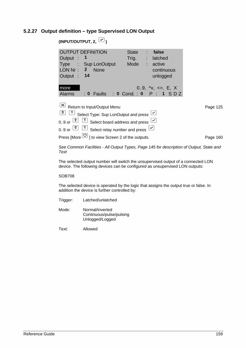
Reference Guide 159
5.2.27 Output definition – type Supervised LON Output
(INPUT/OUTPUT, 2, )
OUTPUT DEFINITION State :Output : Trig. : latchedType : Sup LonOutput Mode : activeLON Nr : None continuousOutput : unlogged
more 0..9, ^v, <>, E, XAlarms : Faults : Cond. : P : S D Z
Return to Input/Output Menu Page 125
Select Type: Sup LonOutput and press
0..9 or Select board address and press
0..9 or Select relay number and press
Press [More ] to view Screen 2 of the outputs. Page 160
See Common Facilities - All Output Types, Page 145 for description of Output, State and Text
The selected output number will switch the unsupervised output of a connected LON device. The following devices can be configured as unsupervised LON outputs:
SOB708 The selected device is operated by the logic that assigns the output true or false. In addition the device is further controlled by:
Trigger: Latched/unlatched
Mode: Normal/inverted Continuous/pulse/pulsing Unlogged/Logged
Text: Allowed
false 1
2 14
0 0 0 1
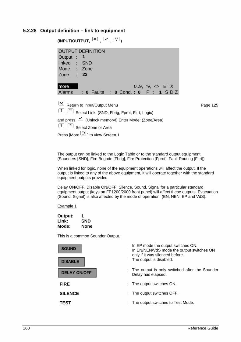
160 Reference Guide
5.2.28 Output definition – link to equipment
(INPUT/OUTPUT, , , )
OUTPUT DEFINITIONOutput :linked : SNDMode : ZoneZone :
more 0..9, ^v, <>, E, XAlarms : Faults : Cond. : P : S D Z
Return to Input/Output Menu Page 125
Select Link: (SND, Fbrig, Fprot, Fltrt, Logic)
and press (Unlock memory!) Enter Mode: (Zone/Area)
Select Zone or Area
Press [More ] to view Screen 1
The output can be linked to the Logic Table or to the standard output equipment (Sounders [SND], Fire Brigade [Fbrig], Fire Protection [Fprot], Fault Routing [Fltrt])
When linked for logic, none of the equipment operations will affect the output. If the output is linked to any of the above equipment, it will operate together with the standard equipment outputs provided.
Delay ON/OFF, Disable ON/OFF, Silence, Sound, Signal for a particular standard equipment output (keys on FP1200/2000 front panel) will affect these outputs. Evacuation (Sound, Signal) is also affected by the mode of operation! (EN, NEN, EP and VdS).
Example 1
Output: 1 Link: SND Mode: None
This is a common Sounder Output.
: In EP mode the output switches ON. In EN/NEN/VdS mode the output switches ON only if it was silenced before.
: The output is disabled.
: The output is only switched after the Sounder Delay has elapsed.
FIRE : The output switches ON.
SILENCE : The output switches OFF.
TEST : The output switches to Test Mode.
SOUND
DISABLE
DELAY ON/OFF
1 23
0 0 0 1
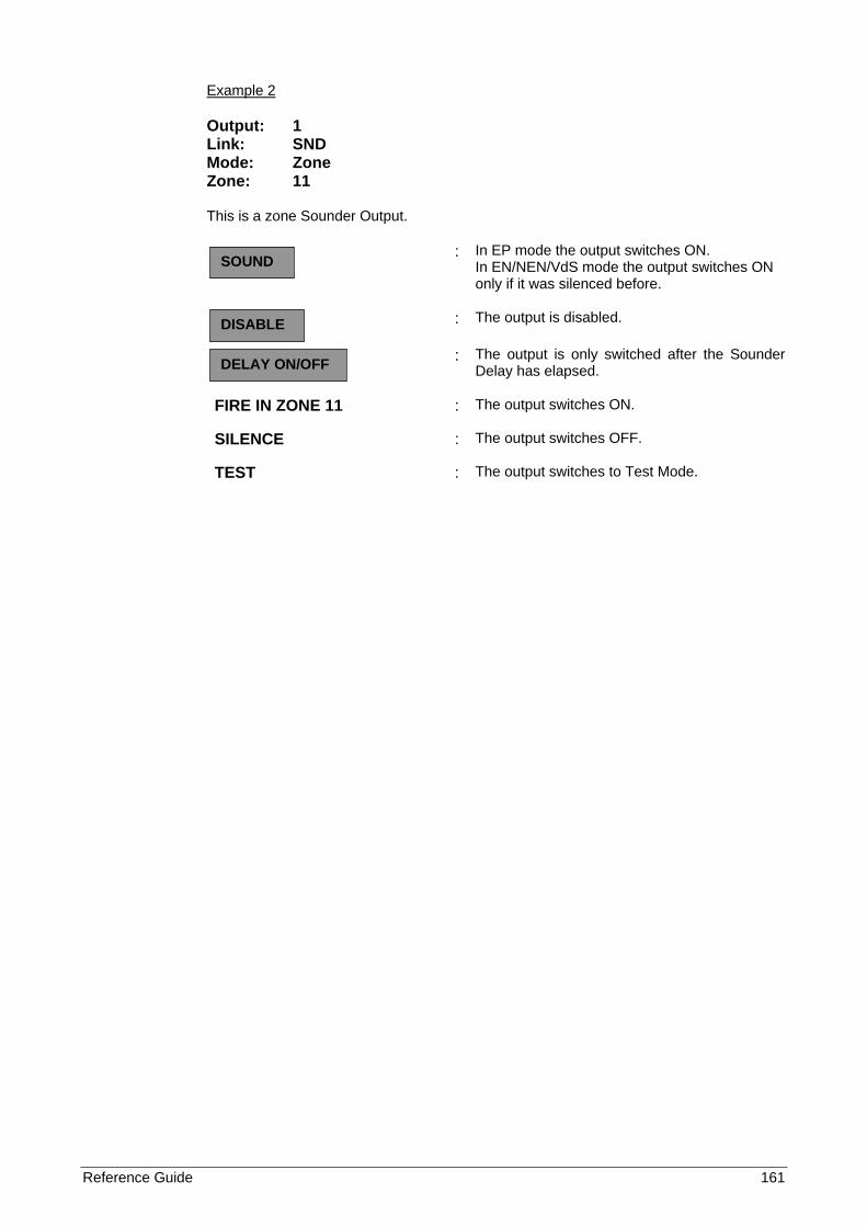
Reference Guide 161
Example 2
Output: 1 Link: SND Mode: Zone Zone: 11
This is a zone Sounder Output.
: In EP mode the output switches ON. In EN/NEN/VdS mode the output switches ON only if it was silenced before.
: The output is disabled.
: The output is only switched after the Sounder Delay has elapsed.
FIRE IN ZONE 11 : The output switches ON.
SILENCE : The output switches OFF.
TEST : The output switches to Test Mode.
SOUND
DISABLE
DELAY ON/OFF
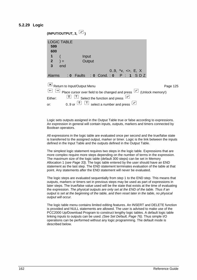
162 Reference Guide
5.2.29 Logic
(INPUT/OUTPUT, 3, )
LOGIC TABLE
( Input) = Outputend
0..9, ^v, <>, E, XAlarms : Faults : Cond. : P : S D Z
Return to Input/Output Menu Page 125
Place cursor over field to be changed and press (Unlock memory!)
Either: Select the function and press
or: 0..9 or select a number and press
Logic sets outputs assigned in the Output Table true or false according to expressions. An expression in general will contain inputs, outputs, markers and timers connected by Boolean operators.
All expressions in the logic table are evaluated once per second and the true/false state is transferred to the assigned output, marker or timer. Logic is the link between the inputs defined in the Input Table and the outputs defined in the Output Table.
The simplest logic statement requires two steps in the logic table. Expressions that are more complex require more steps depending on the number of terms in the expression. The maximum size of the logic table (default 300 steps) can be set in Memory Allocation 1 (see Page 33). The logic table entered by the user should have an END statement as the last step. The END statement terminates evaluation of the table at that point. Any statements after the END statement will never be evaluated.
The logic steps are evaluated sequentially from step 1 to the END step. This means that outputs, markers or timers set in previous steps may be used as part of expressions in later steps. The true/false value used will be the state that exists at the time of evaluating the expression. The physical outputs are only set at the END of the table. Thus if an output is set at the beginning of the table, and then reset later in the table, no physical output will occur.
The logic table menu contains limited editing features. An INSERT and DELETE function is provided and NULL statements are allowed. The user is advised to make use of the PCC2000 Up/Download Program to construct lengthy logic tables. A default logic table linking inputs to outputs can be used. (See Set Default, Page 76). Thus simple I/O operations can be performed without any logic programming. The default mode is described below.
599 600 1 2 3 0 0 0 1
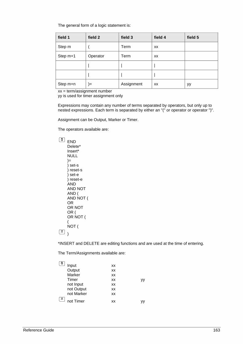
Reference Guide 163
The general form of a logic statement is:
field 1 field 2 field 3 field 4 field 5
Step m ( Term xx
Step m+1 Operator Term xx
| | |
| | |
Step m+n )= Assignment xx yy
xx = term/assignment number yy is used for timer assignment only
Expressions may contain any number of terms separated by operators, but only up to nested expressions. Each term is separated by either an "(" or operator or operator ")".
Assignment can be Output, Marker or Timer.
The operators available are:
END Delete* Insert* NULL )= ) set-s ) reset-s ) set-e ) reset-e AND AND NOT AND ( AND NOT ( OR OR NOT OR ( OR NOT ( ( NOT (
)
*INSERT and DELETE are editing functions and are used at the time of entering.
The Term/Assignments available are:
Input xx Output xx Marker xx Timer xx yy not Input xx not Output xx not Marker xx
not Timer xx yy
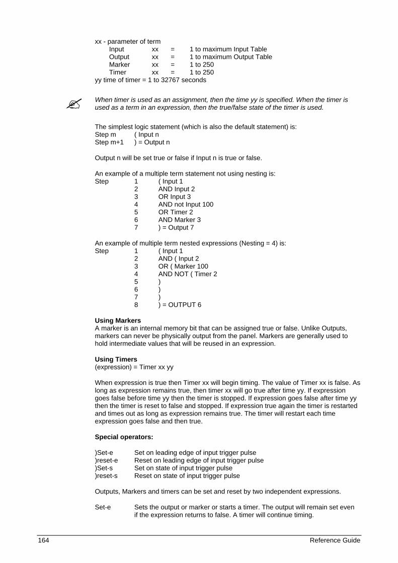
164 Reference Guide
xx - parameter of term Input xx = 1 to maximum Input Table Output xx = 1 to maximum Output Table Marker xx = 1 to 250 Timer xx = 1 to 250 yy time of timer = 1 to 32767 seconds
When timer is used as an assignment, then the time yy is specified. When the timer is used as a term in an expression, then the true/false state of the timer is used.
The simplest logic statement (which is also the default statement) is: Step m ( Input n Step m+1 ) = Output n
Output n will be set true or false if Input n is true or false.
An example of a multiple term statement not using nesting is: Step 1 ( Input 1 2 AND Input 2 3 OR Input 3 4 AND not Input 100 5 OR Timer 2 6 AND Marker 3 7 ) = Output 7
An example of multiple term nested expressions (Nesting = 4) is: Step 1 ( Input 1 2 AND ( Input 2 3 OR ( Marker 100 4 AND NOT ( Timer 2 5 ) 6 ) 7 ) 8 ) = OUTPUT 6
Using Markers A marker is an internal memory bit that can be assigned true or false. Unlike Outputs, markers can never be physically output from the panel. Markers are generally used to hold intermediate values that will be reused in an expression.
Using Timers (expression) = Timer xx yy
When expression is true then Timer xx will begin timing. The value of Timer xx is false. As long as expression remains true, then timer xx will go true after time yy. If expression goes false before time yy then the timer is stopped. If expression goes false after time yy then the timer is reset to false and stopped. If expression true again the timer is restarted and times out as long as expression remains true. The timer will restart each time expression goes false and then true.
Special operators:
)Set-e Set on leading edge of input trigger pulse )reset-e Reset on leading edge of input trigger pulse )Set-s Set on state of input trigger pulse )reset-s Reset on state of input trigger pulse
Outputs, Markers and timers can be set and reset by two independent expressions.
Set-e Sets the output or marker or starts a timer. The output will remain set even if the expression returns to false. A timer will continue timing.

Reference Guide 165
reset-e Resets the output or stops the timer. Set-s Sets the output or marker or starts a timer. The output will remain set even if the expression returns to false. A timer will continue timing.reset-s Resets the output or stops the timer.
Editing
INSERT - Selecting Insert and pressing in the operator field will insert a blank line above the current line. DELETE - Deletes the current line.
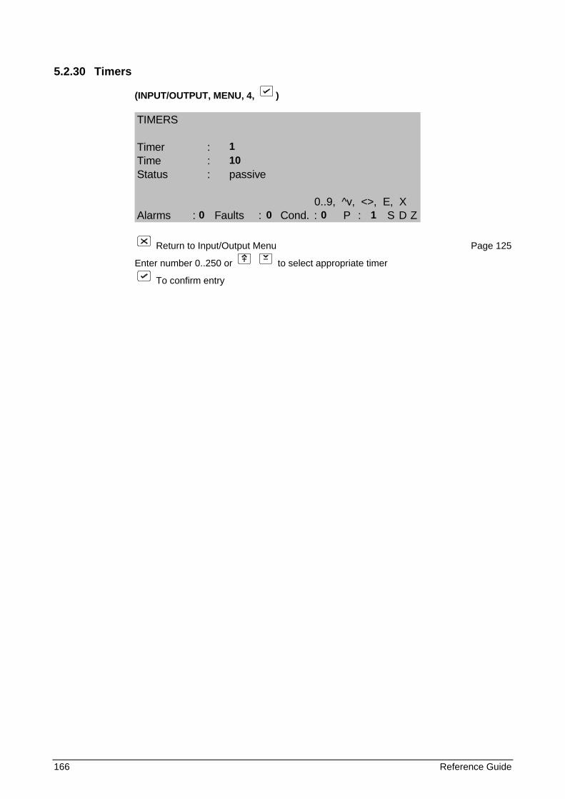
166 Reference Guide
5.2.30 Timers
(INPUT/OUTPUT, MENU, 4, )
TIMERS
Timer :Time :Status : passive
0..9, ^v, <>, E, XAlarms : Faults : Cond. : P : S D Z
Return to Input/Output Menu Page 125
Enter number 0..250 or to select appropriate timer
To confirm entry
1 10
0 0 0 1
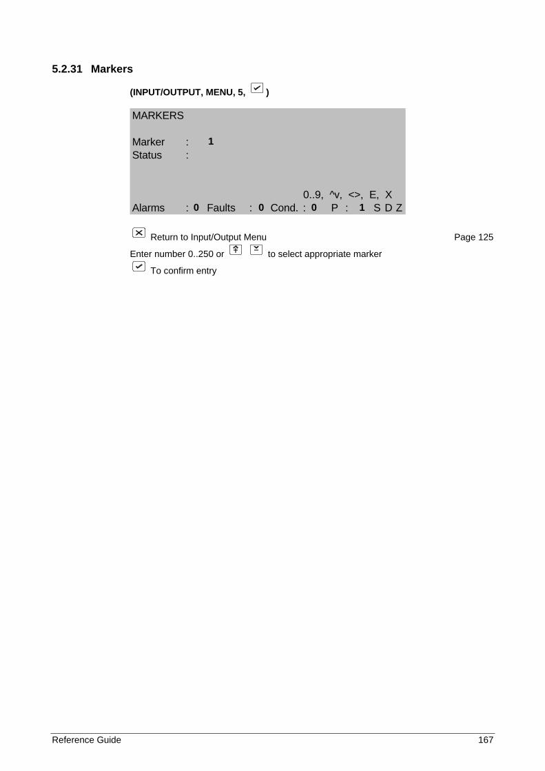
Reference Guide 167
5.2.31 Markers
(INPUT/OUTPUT, MENU, 5, )
MARKERS
Marker :Status :
0..9, ^v, <>, E, XAlarms : Faults : Cond. : P : S D Z
Return to Input/Output Menu Page 125
Enter number 0..250 or to select appropriate marker
To confirm entry
1
0 0 0 1
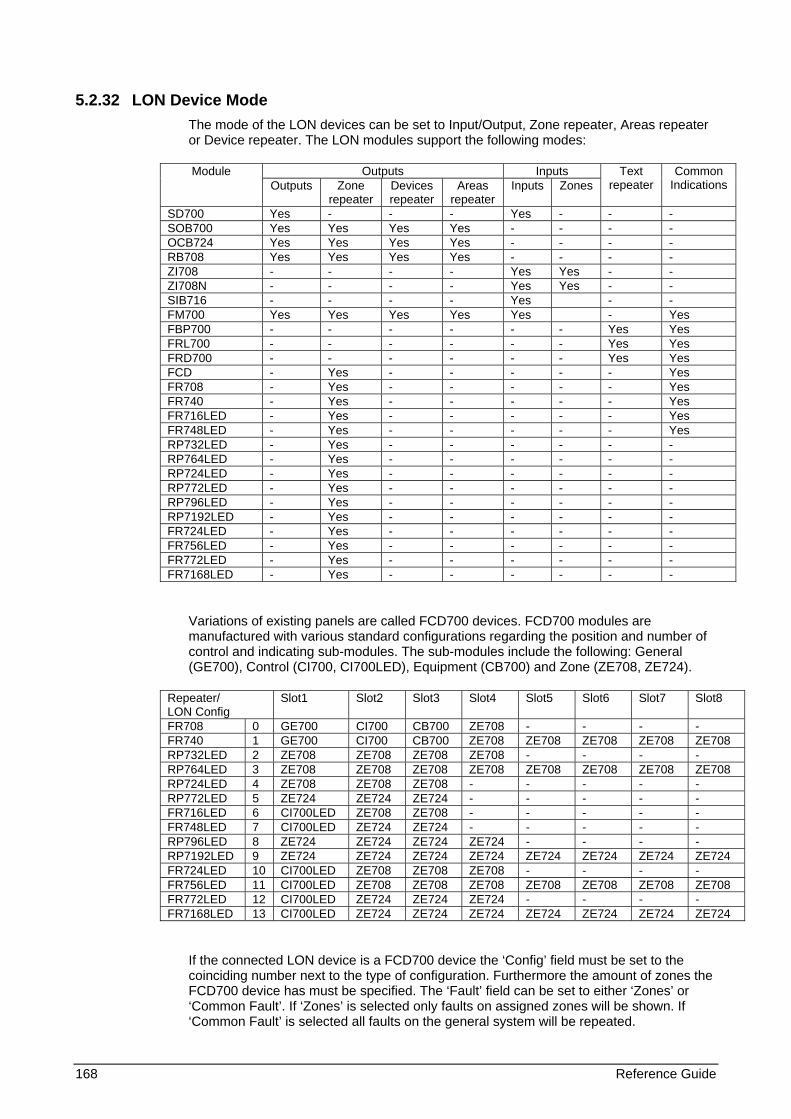
168 Reference Guide
5.2.32 LON Device Mode The mode of the LON devices can be set to Input/Output, Zone repeater, Areas repeater or Device repeater. The LON modules support the following modes:
Outputs Inputs Module Outputs Zone
repeater Devices repeater
Areas repeater
Inputs Zones Text
repeater Common
Indications
SD700 Yes - - - Yes - - - SOB700 Yes Yes Yes Yes - - - - OCB724 Yes Yes Yes Yes - - - - RB708 Yes Yes Yes Yes - - - - ZI708 - - - - Yes Yes - - ZI708N - - - - Yes Yes - - SIB716 - - - - Yes - - FM700 Yes Yes Yes Yes Yes - Yes FBP700 - - - - - - Yes Yes FRL700 - - - - - - Yes Yes FRD700 - - - - - - Yes Yes FCD - Yes - - - - - Yes FR708 - Yes - - - - - Yes FR740 - Yes - - - - - Yes FR716LED - Yes - - - - - Yes FR748LED - Yes - - - - - Yes RP732LED - Yes - - - - - - RP764LED - Yes - - - - - - RP724LED - Yes - - - - - - RP772LED - Yes - - - - - - RP796LED - Yes - - - - - - RP7192LED - Yes - - - - - - FR724LED - Yes - - - - - - FR756LED - Yes - - - - - - FR772LED - Yes - - - - - - FR7168LED - Yes - - - - - -
Variations of existing panels are called FCD700 devices. FCD700 modules are manufactured with various standard configurations regarding the position and number of control and indicating sub-modules. The sub-modules include the following: General (GE700), Control (CI700, CI700LED), Equipment (CB700) and Zone (ZE708, ZE724).
Repeater/ LON Config
Slot1 Slot2 Slot3 Slot4 Slot5 Slot6 Slot7 Slot8
FR708 0 GE700 CI700 CB700 ZE708 - - - - FR740 1 GE700 CI700 CB700 ZE708 ZE708 ZE708 ZE708 ZE708 RP732LED 2 ZE708 ZE708 ZE708 ZE708 - - - - RP764LED 3 ZE708 ZE708 ZE708 ZE708 ZE708 ZE708 ZE708 ZE708 RP724LED 4 ZE708 ZE708 ZE708 - - - - - RP772LED 5 ZE724 ZE724 ZE724 - - - - - FR716LED 6 CI700LED ZE708 ZE708 - - - - - FR748LED 7 CI700LED ZE724 ZE724 - - - - - RP796LED 8 ZE724 ZE724 ZE724 ZE724 - - - - RP7192LED 9 ZE724 ZE724 ZE724 ZE724 ZE724 ZE724 ZE724 ZE724 FR724LED 10 CI700LED ZE708 ZE708 ZE708 - - - - FR756LED 11 CI700LED ZE708 ZE708 ZE708 ZE708 ZE708 ZE708 ZE708 FR772LED 12 CI700LED ZE724 ZE724 ZE724 - - - - FR7168LED 13 CI700LED ZE724 ZE724 ZE724 ZE724 ZE724 ZE724 ZE724
If the connected LON device is a FCD700 device the ‘Config’ field must be set to the coinciding number next to the type of configuration. Furthermore the amount of zones the FCD700 device has must be specified. The ‘Fault’ field can be set to either ‘Zones’ or ‘Common Fault’. If ‘Zones’ is selected only faults on assigned zones will be shown. If ‘Common Fault’ is selected all faults on the general system will be repeated.
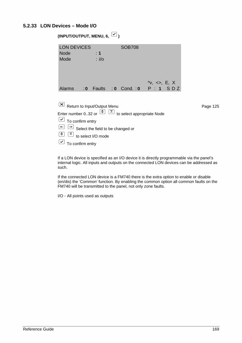
Reference Guide 169
5.2.33 LON Devices – Mode I/O
(INPUT/OUTPUT, MENU, 6, )
Return to Input/Output Menu Page 125
Enter number 0..32 or to select appropriate Node
To confirm entry
Select the field to be changed or
to select I/O mode
To confirm entry
If a LON device is specified as an I/O device it is directly programmable via the panel’s internal logic. All inputs and outputs on the connected LON devices can be addressed as such.
If the connected LON device is a FM740 there is the extra option to enable or disable (en/dis) the ‘Common’ function. By enabling the common option all common faults on the FM740 will be transmitted to the panel, not only zone faults.
I/O - All points used as outputs
LON DEVICES SOB708Node :Mode : i/o
^v, <>, E, XAlarms : Faults : Cond. : P : S D Z
1
0 0 0 1
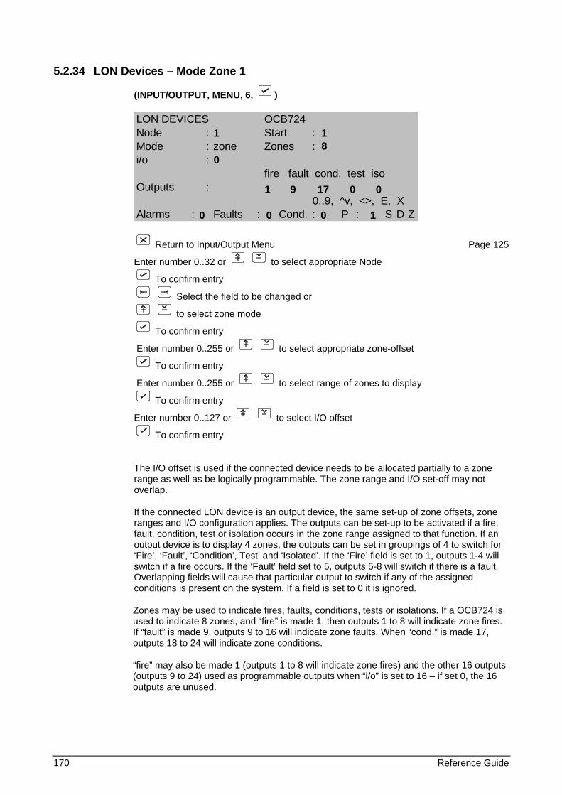
170 Reference Guide
5.2.34 LON Devices – Mode Zone 1
(INPUT/OUTPUT, MENU, 6, )
LON DEVICES OCB724Node : Start :Mode : zone Zones :i/o :
fire fault cond. test isoOutputs :
0..9, ^v, <>, E, XAlarms : Faults : Cond. : P : S D Z
Return to Input/Output Menu Page 125
Enter number 0..32 or to select appropriate Node
To confirm entry
Select the field to be changed or
to select zone mode
To confirm entry
Enter number 0..255 or to select appropriate zone-offset
To confirm entry
Enter number 0..255 or to select range of zones to display
To confirm entry
Enter number 0..127 or to select I/O offset
To confirm entry
The I/O offset is used if the connected device needs to be allocated partially to a zone range as well as be logically programmable. The zone range and I/O set-off may not overlap.
If the connected LON device is an output device, the same set-up of zone offsets, zone ranges and I/O configuration applies. The outputs can be set-up to be activated if a fire, fault, condition, test or isolation occurs in the zone range assigned to that function. If an output device is to display 4 zones, the outputs can be set in groupings of 4 to switch for ‘Fire’, ‘Fault’, ‘Condition’, Test’ and ‘Isolated’. If the ‘Fire’ field is set to 1, outputs 1-4 will switch if a fire occurs. If the ‘Fault’ field set to 5, outputs 5-8 will switch if there is a fault. Overlapping fields will cause that particular output to switch if any of the assigned conditions is present on the system. If a field is set to 0 it is ignored.
Zones may be used to indicate fires, faults, conditions, tests or isolations. If a OCB724 is used to indicate 8 zones, and “fire” is made 1, then outputs 1 to 8 will indicate zone fires. If “fault” is made 9, outputs 9 to 16 will indicate zone faults. When “cond.” is made 17, outputs 18 to 24 will indicate zone conditions.
“fire” may also be made 1 (outputs 1 to 8 will indicate zone fires) and the other 16 outputs (outputs 9 to 24) used as programmable outputs when “i/o” is set to 16 – if set 0, the 16 outputs are unused.
1 1 8 0
1 9 17 0 0
0 0 0 1
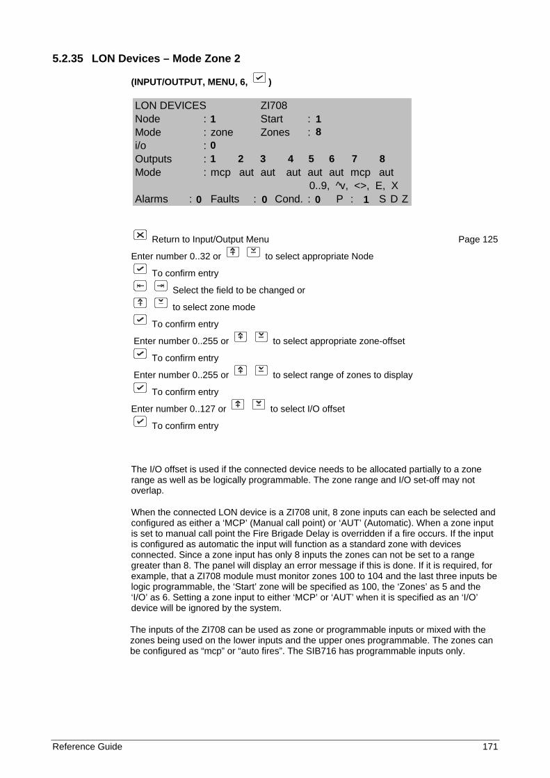
Reference Guide 171
5.2.35 LON Devices – Mode Zone 2
(INPUT/OUTPUT, MENU, 6, )
Return to Input/Output Menu Page 125
Enter number 0..32 or to select appropriate Node
To confirm entry
Select the field to be changed or
to select zone mode
To confirm entry
Enter number 0..255 or to select appropriate zone-offset
To confirm entry
Enter number 0..255 or to select range of zones to display
To confirm entry
Enter number 0..127 or to select I/O offset
To confirm entry
The I/O offset is used if the connected device needs to be allocated partially to a zone range as well as be logically programmable. The zone range and I/O set-off may not overlap.
When the connected LON device is a ZI708 unit, 8 zone inputs can each be selected and configured as either a ‘MCP’ (Manual call point) or ‘AUT’ (Automatic). When a zone input is set to manual call point the Fire Brigade Delay is overridden if a fire occurs. If the input is configured as automatic the input will function as a standard zone with devices connected. Since a zone input has only 8 inputs the zones can not be set to a range greater than 8. The panel will display an error message if this is done. If it is required, for example, that a ZI708 module must monitor zones 100 to 104 and the last three inputs be logic programmable, the ‘Start’ zone will be specified as 100, the ‘Zones’ as 5 and the ‘I/O’ as 6. Setting a zone input to either ‘MCP’ or ‘AUT’ when it is specified as an ‘I/O’ device will be ignored by the system.
The inputs of the ZI708 can be used as zone or programmable inputs or mixed with the zones being used on the lower inputs and the upper ones programmable. The zones can be configured as “mcp” or “auto fires”. The SIB716 has programmable inputs only.
LON DEVICES ZI708Node : Start :Mode : zone Zones :i/o :Outputs :Mode : mcp aut aut aut aut aut mcp aut
0..9, ^v, <>, E, XAlarms : Faults : Cond. : P : S D Z
1 1 8 0 1 2 3 4 5 6 7 8
0 0 0 1
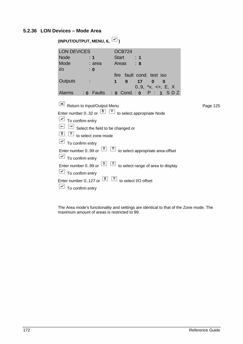
172 Reference Guide
5.2.36 LON Devices – Mode Area
(INPUT/OUTPUT, MENU, 6, )
LON DEVICES OCB724Node : Start :Mode : area Areas :i/o :
fire fault cond. test isoOutputs :
0..9, ^v, <>, E, XAlarms : Faults : Cond. : P : S D Z
Return to Input/Output Menu Page 125
Enter number 0..32 or to select appropriate Node
To confirm entry
Select the field to be changed or
to select zone mode
To confirm entry
Enter number 0..99 or to select appropriate area-offset
To confirm entry
Enter number 0..99 or to select range of area to display
To confirm entry
Enter number 0..127 or to select I/O offset
To confirm entry
The Area mode’s functionality and settings are identical to that of the Zone mode. The maximum amount of areas is restricted to 99.
1 1 8 0
1 9 17 0 0
0 0 0 1
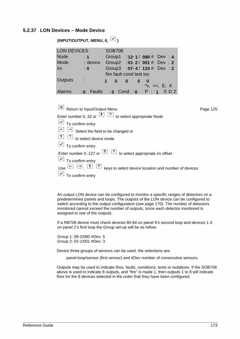
Reference Guide 173
5.2.37 LON Devices – Mode Device
(INPUT/OUTPUT, MENU, 6, )
Return to Input/Output Menu Page 125
Enter number 0..32 or to select appropriate Node
To confirm entry
Select the field to be changed or
to select device mode
To confirm entry
Enter number 0..127 or to select appropriate i/o offset
To confirm entry
Use , keys to select device location and number of devices
To confirm entry
An output LON device can be configured to monitor a specific ranges of detectors on a predetermined panels and loops. The outputs of the LON device can be configured to switch according to the output configuration (see page 170). The number of detectors monitored cannot exceed the number of outputs, since each detector monitored is assigned to one of the outputs.
If a RB708 device must check devices 80-84 on panel 9’s second loop and devices 1-3 on panel 2’s first loop the Group set-up will be as follow:
Group 1: 09-2/080 #Dev: 5 Group 2: 02-1/001 #Dev: 3
Device three groups of sensors can be used, the selections are:
panel-loop/sensor (first sensor) and #Dev number of consecutive sensors.
Outputs may be used to indicate fires, faults, conditions, tests or isolations. If the SOB708 above is used to indicate 8 outputs, and “fire” is made 1, then outputs 1 to 8 will indicate fires for the 8 devices selected in the order that they have been configured.
LON DEVICES SOB708Node : Group1 : - / # Dev :Mode : device Group2 : - / # Dev :i/o : Group3 : - / # Dev :
fire fault cond test isoOutputs :
^v, <>, E, XAlarms : Faults : Cond. : P : S D Z
1 12 1 090 4 01 2 001 2 0 07 4 110 2 1 0 0 0 0
0 0 0 1
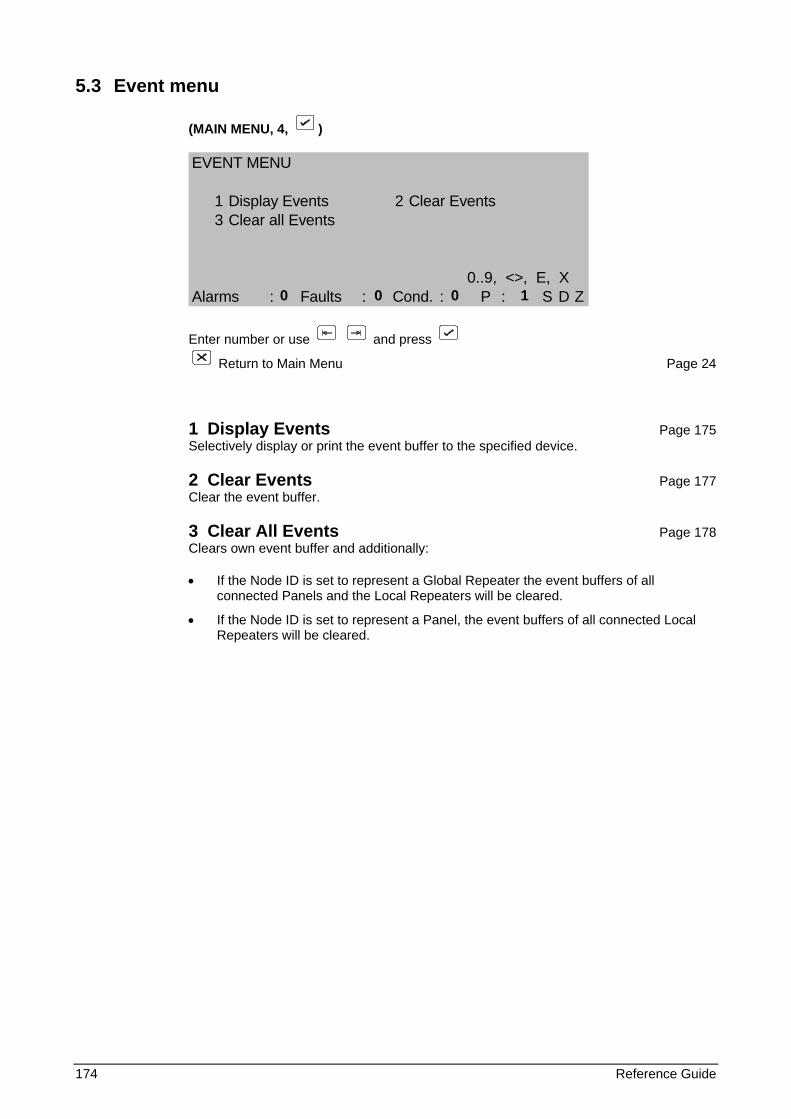
174 Reference Guide
5.3 Event menu
(MAIN MENU, 4, )
EVENT MENU
1 Display Events 2 Clear Events3 Clear all Events
0..9, <>, E, XAlarms : Faults : Cond. : P : S D Z
Enter number or use and press
Return to Main Menu Page 24
1 Display Events Page 175 Selectively display or print the event buffer to the specified device.
2 Clear Events Page 177 Clear the event buffer.
3 Clear All Events Page 178 Clears own event buffer and additionally:
• If the Node ID is set to represent a Global Repeater the event buffers of all connected Panels and the Local Repeaters will be cleared.
• If the Node ID is set to represent a Panel, the event buffers of all connected Local Repeaters will be cleared.
0 0 0 1
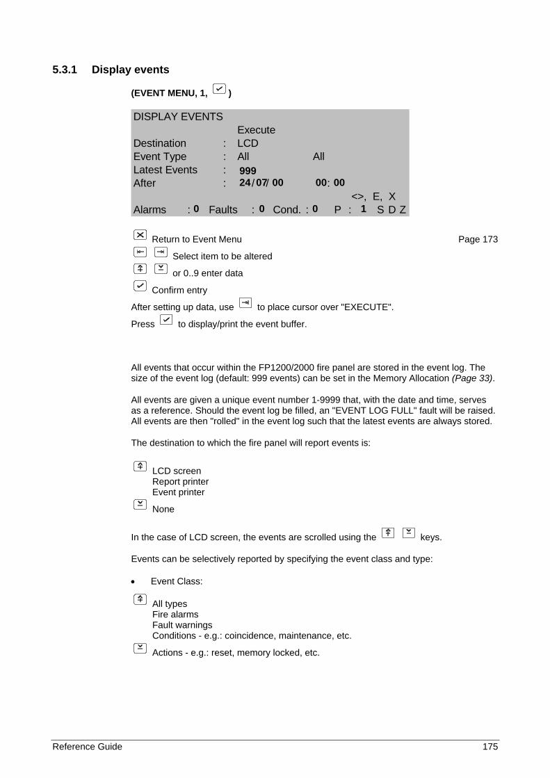
Reference Guide 175
5.3.1 Display events
(EVENT MENU, 1, )
DISPLAY EVENTSExecute
Destination : LCDEvent Type : All AllLatest Events :After : / / :
<>, E, XAlarms : Faults : Cond. : P : S D Z
Return to Event Menu Page 173
Select item to be altered
or 0..9 enter data
Confirm entry
After setting up data, use to place cursor over "EXECUTE".
Press to display/print the event buffer.
All events that occur within the FP1200/2000 fire panel are stored in the event log. The size of the event log (default: 999 events) can be set in the Memory Allocation (Page 33).
All events are given a unique event number 1-9999 that, with the date and time, serves as a reference. Should the event log be filled, an "EVENT LOG FULL" fault will be raised. All events are then "rolled" in the event log such that the latest events are always stored.
The destination to which the fire panel will report events is:
LCD screen Report printer Event printer
None
In the case of LCD screen, the events are scrolled using the keys.
Events can be selectively reported by specifying the event class and type:
• Event Class:
All types Fire alarms Fault warnings Conditions - e.g.: coincidence, maintenance, etc.
Actions - e.g.: reset, memory locked, etc.
999 24 07 00 00 00
0 0 0 1
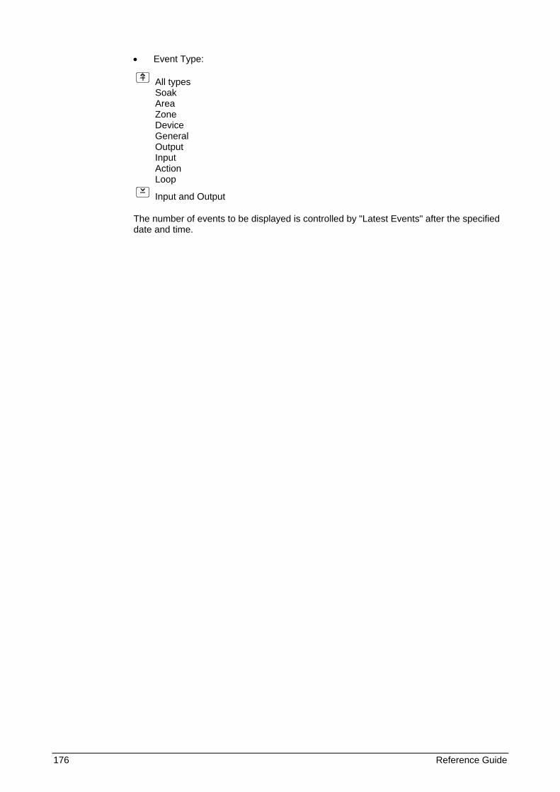
176 Reference Guide
• Event Type:
All types Soak Area Zone Device General Output Input Action Loop
Input and Output
The number of events to be displayed is controlled by "Latest Events" after the specified date and time.
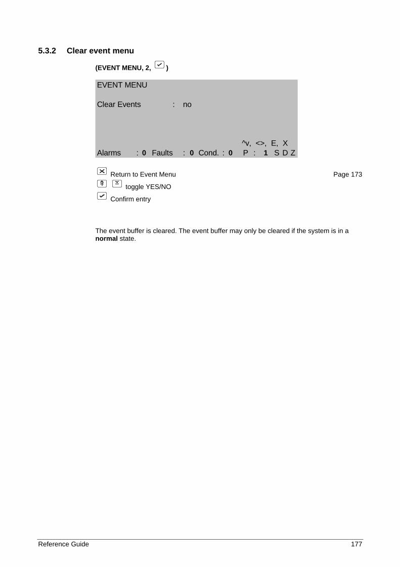
Reference Guide 177
5.3.2 Clear event menu
(EVENT MENU, 2, )
EVENT MENU
Clear Events : no
^v, <>, E, XAlarms : Faults : Cond. : P : S D Z
Return to Event Menu Page 173
toggle YES/NO
Confirm entry
The event buffer is cleared. The event buffer may only be cleared if the system is in a normal state.
0 0 0 1
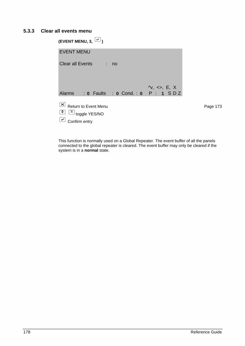
178 Reference Guide
5.3.3 Clear all events menu
(EVENT MENU, 3, )
EVENT MENU
Clear all Events : no
^v, <>, E, XAlarms : Faults : Cond. : P : S D Z
Return to Event Menu Page 173
toggle YES/NO
Confirm entry
This function is normally used on a Global Repeater. The event buffer of all the panels connected to the global repeater is cleared. The event buffer may only be cleared if the system is in a normal state.
0 0 0 1
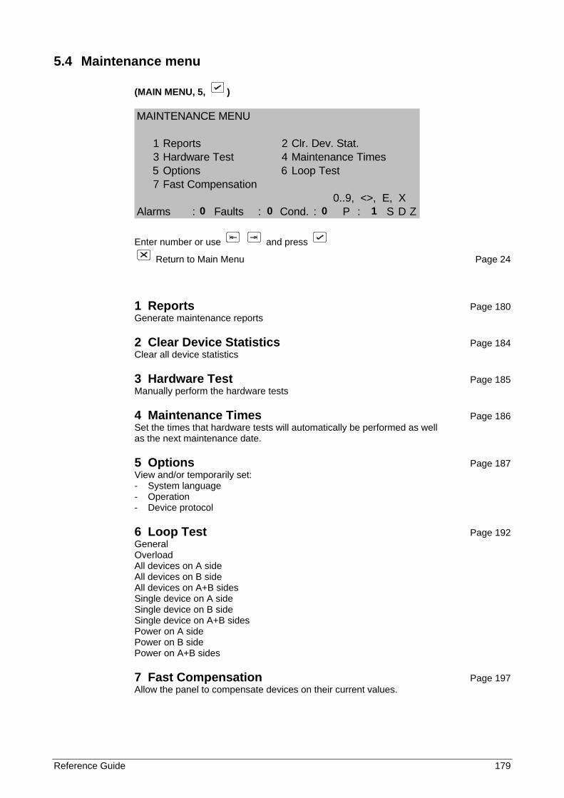
Reference Guide 179
5.4 Maintenance menu
(MAIN MENU, 5, )
MAINTENANCE MENU
1 Reports 2 Clr. Dev. Stat.3 Hardware Test 4 Maintenance Times5 Options 6 Loop Test7 Fast Compensation
0..9, <>, E, XAlarms : Faults : Cond. : P : S D Z
Enter number or use and press
Return to Main Menu Page 24
1 Reports Page 180 Generate maintenance reports
2 Clear Device Statistics Page 184 Clear all device statistics
3 Hardware Test Page 185 Manually perform the hardware tests
4 Maintenance Times Page 186 Set the times that hardware tests will automatically be performed as well as the next maintenance date.
5 Options Page 187 View and/or temporarily set: - System language - Operation - Device protocol
6 Loop Test Page 192 General Overload All devices on A side All devices on B side All devices on A+B sides Single device on A side Single device on B side Single device on A+B sides Power on A side Power on B side Power on A+B sides
7 Fast Compensation Page 197 Allow the panel to compensate devices on their current values.
0 0 0 1
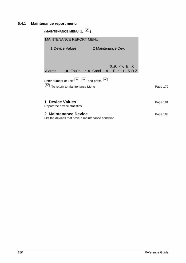
180 Reference Guide
5.4.1 Maintenance report menu
(MAINTENANCE MENU, 1, )
MAINTENANCE REPORT MENU
1 Device Values 2 Maintenance Dev.
0..9, <>, E, XAlarms : Faults : Cond. : P : S D Z
Enter number or use and press
To return to Maintenance Menu Page 179
1 Device Values Page 181 Report the device statistics
2 Maintenance Device Page 183 List the devices that have a maintenance condition
0 0 0 1
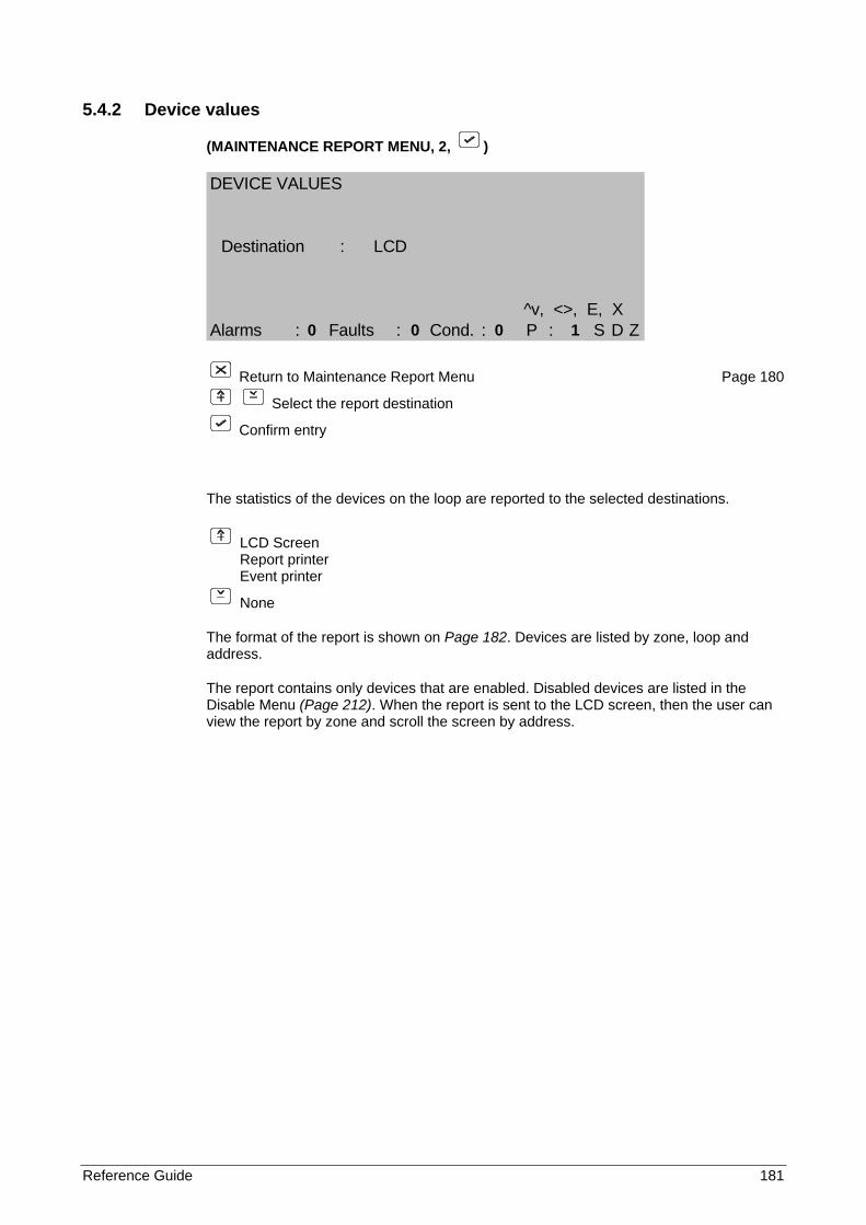
Reference Guide 181
5.4.2 Device values
(MAINTENANCE REPORT MENU, 2, )
DEVICE VALUES
Destination : LCD
^v, <>, E, XAlarms : Faults : Cond. : P : S D Z
Return to Maintenance Report Menu Page 180
Select the report destination
Confirm entry
The statistics of the devices on the loop are reported to the selected destinations.
LCD Screen Report printer Event printer
None
The format of the report is shown on Page 182. Devices are listed by zone, loop and address.
The report contains only devices that are enabled. Disabled devices are listed in the Disable Menu (Page 212). When the report is sent to the LCD screen, then the user can view the report by zone and scroll the screen by address.
0 0 0 1
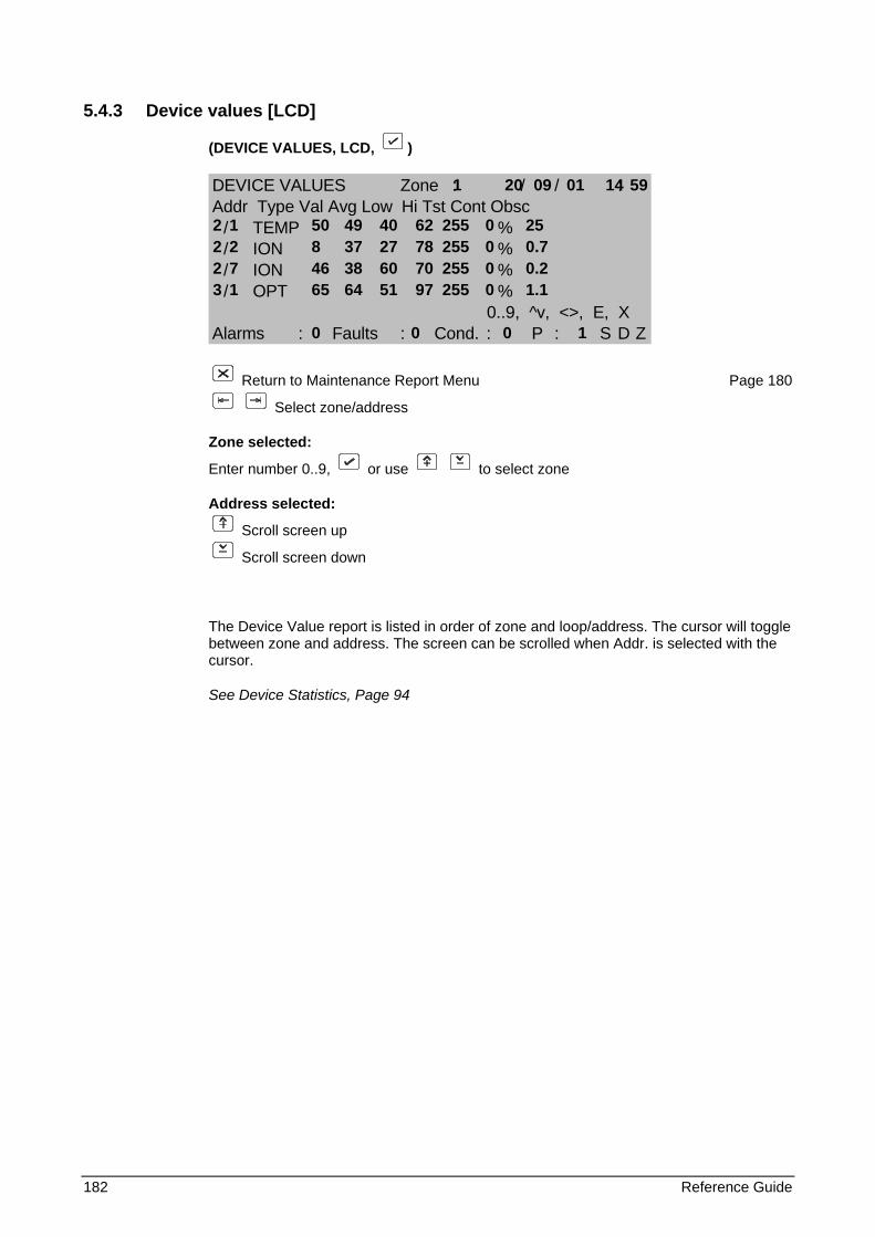
182 Reference Guide
5.4.3 Device values [LCD]
(DEVICE VALUES, LCD, )
DEVICE VALUES Zone : / / :Addr Type Val Avg Low Hi Tst Cont Obsc
/ TEMP %/ ION %/ ION %/ OPT %
0..9, ^v, <>, E, XAlarms : Faults : Cond. : P : S D Z
Return to Maintenance Report Menu Page 180
Select zone/address
Zone selected:
Enter number 0..9, or use to select zone
Address selected:
Scroll screen up
Scroll screen down
The Device Value report is listed in order of zone and loop/address. The cursor will toggle between zone and address. The screen can be scrolled when Addr. is selected with the cursor.
See Device Statistics, Page 94
1 20 09 01 14 59
2 1 50 49 40 62 255 0 25 2 2 8 37 27 78 255 0 0.7 2 7 46 38 60 70 255 0 0.2 3 1 65 64 51 97 255 0 1.1 0 0 0 1
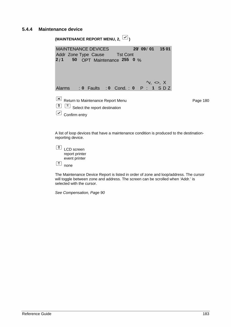
Reference Guide 183
5.4.4 Maintenance device
(MAINTENANCE REPORT MENU, 2, )
MAINTENANCE DEVICES / / :Addr Zone Type Cause Tst Cont
/ OPT Maintenance %
^v, <>, XAlarms : Faults : Cond. : P : S D Z
Return to Maintenance Report Menu Page 180
Select the report destination
Confirm entry
A list of loop devices that have a maintenance condition is produced to the destination-reporting device.
LCD screen report printer event printer
none
The Maintenance Device Report is listed in order of zone and loop/address. The cursor will toggle between zone and address. The screen can be scrolled when ‘Addr.’ is selected with the cursor.
See Compensation, Page 90
20 09 01 15 01
2 1 50 255 0 0 0 0 1
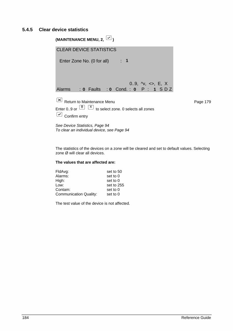
184 Reference Guide
5.4.5 Clear device statistics
(MAINTENANCE MENU, 2, )
CLEAR DEVICE STATISTICS
Enter Zone No. (0 for all) :
0..9, ^v, <>, E, XAlarms : Faults : Cond. : P : S D Z
Return to Maintenance Menu Page 179
Enter 0..9 or to select zone. 0 selects all zones
Confirm entry
See Device Statistics, Page 94 To clear an individual device, see Page 94
The statistics of the devices on a zone will be cleared and set to default values. Selecting zone Ø will clear all devices.
The values that are affected are:
FldAvg: set to 50 Alarms: set to 0 High: set to 0 Low: set to 255 Contam: set to 0 Communication Quality: set to 0
The test value of the device is not affected.
1 0 0 0 1
Reference Guide 185
5.4.6 Hardware test
(MAINTENANCE MENU, 3, )
The FP1200/2000 performs system tests once per hour. These tests check the memory integrity of the host CPU system including the locked site data memory, as well as the FEP memory system.
Invoking the hardware test from the maintenance menu causes a system test to be immediately performed.
Any failure during the automatic tests or manual test will be reported as a hardware fault identifying the problem area.
A checksum fault indicates that the memory block is corrupted or faulty. The block should be cleared using "Clear Site Data" (see Page 73) and the data reloaded. If the fault persists it is probable that the memory is faulty. Note carefully the faults reported by the panel and contact your supplier.
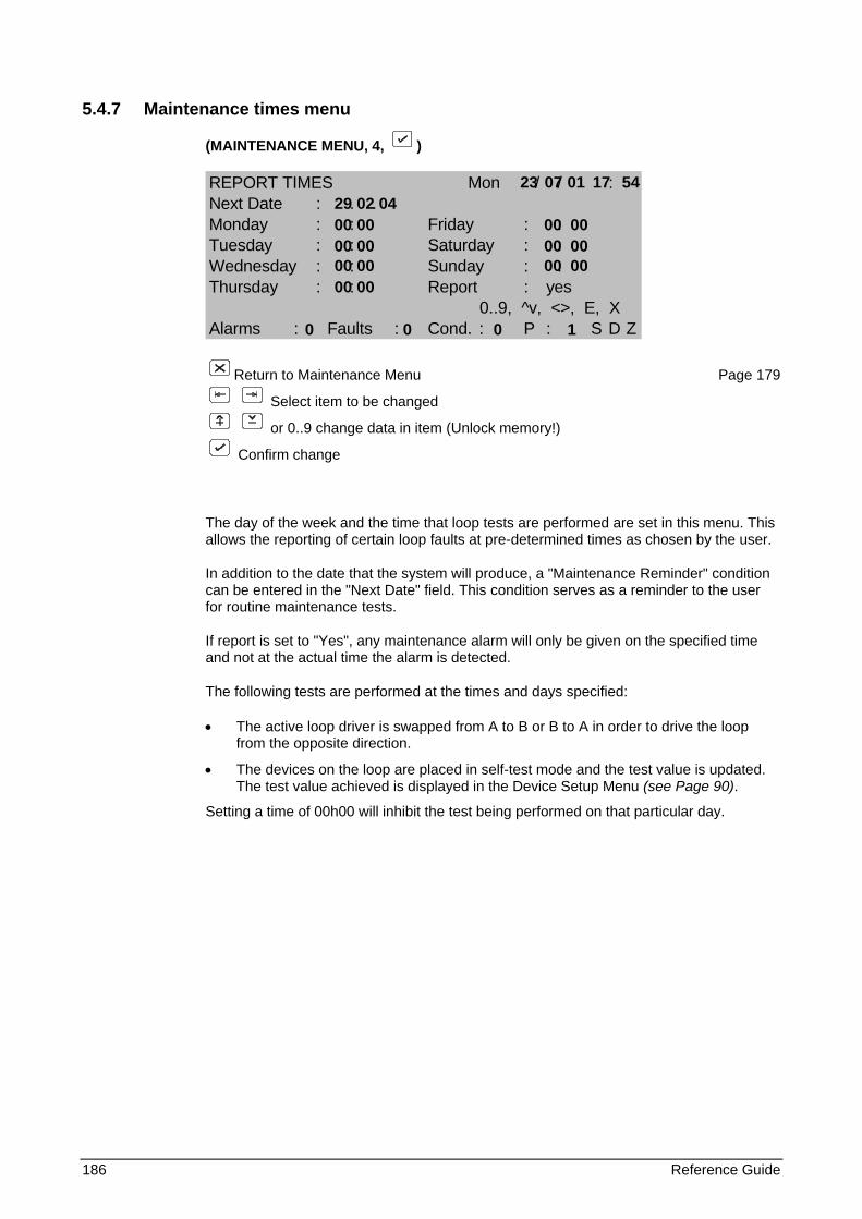
186 Reference Guide
5.4.7 Maintenance times menu
(MAINTENANCE MENU, 4, )
REPORT TIMES Mon / / :Next Date : . .Monday : : Friday : :Tuesday : : Saturday : :Wednesday : : Sunday : :Thursday : : Report : yes
0..9, ^v, <>, E, XAlarms : Faults : Cond. : P : S D Z
Return to Maintenance Menu Page 179
Select item to be changed
or 0..9 change data in item (Unlock memory!)
Confirm change
The day of the week and the time that loop tests are performed are set in this menu. This allows the reporting of certain loop faults at pre-determined times as chosen by the user.
In addition to the date that the system will produce, a "Maintenance Reminder" condition can be entered in the "Next Date" field. This condition serves as a reminder to the user for routine maintenance tests.
If report is set to "Yes", any maintenance alarm will only be given on the specified time and not at the actual time the alarm is detected.
The following tests are performed at the times and days specified:
• The active loop driver is swapped from A to B or B to A in order to drive the loop from the opposite direction.
• The devices on the loop are placed in self-test mode and the test value is updated. The test value achieved is displayed in the Device Setup Menu (see Page 90).
Setting a time of 00h00 will inhibit the test being performed on that particular day.
23 07 01 17 54 29 02 04 00 00 00 00 00 00 00 00 00 00 00 00 00 00
0 0 0 1
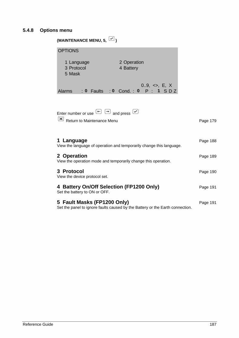
Reference Guide 187
5.4.8 Options menu
(MAINTENANCE MENU, 5, )
OPTIONS
1 Language 2 Operation3 Protocol 4 Battery5 Mask
0..9, <>, E, XAlarms : Faults : Cond. : P : S D Z
Enter number or use and press
Return to Maintenance Menu Page 179
1 Language Page 188 View the language of operation and temporarily change this language.
2 Operation Page 189 View the operation mode and temporarily change this operation.
3 Protocol Page 190 View the device protocol set.
4 Battery On/Off Selection (FP1200 Only) Page 191 Set the battery to ON or OFF.
5 Fault Masks (FP1200 Only) Page 191 Set the panel to ignore faults caused by the Battery or the Earth connection.
0 0 0 1
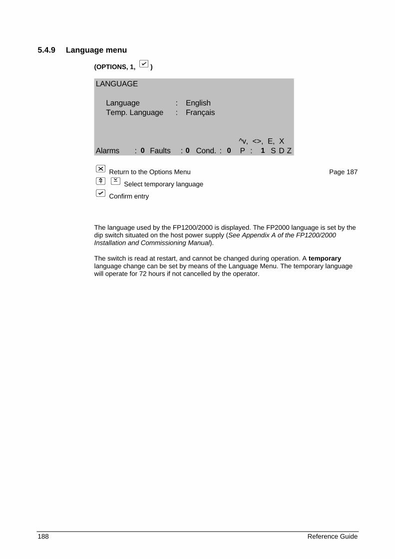
188 Reference Guide
5.4.9 Language menu
(OPTIONS, 1, )
LANGUAGE
Language : EnglishTemp. Language : Français
^v, <>, E, XAlarms : Faults : Cond. : P : S D Z
Return to the Options Menu Page 187
Select temporary language
Confirm entry
The language used by the FP1200/2000 is displayed. The FP2000 language is set by the dip switch situated on the host power supply (See Appendix A of the FP1200/2000 Installation and Commissioning Manual).
The switch is read at restart, and cannot be changed during operation. A temporary language change can be set by means of the Language Menu. The temporary language will operate for 72 hours if not cancelled by the operator.
0 0 0 1
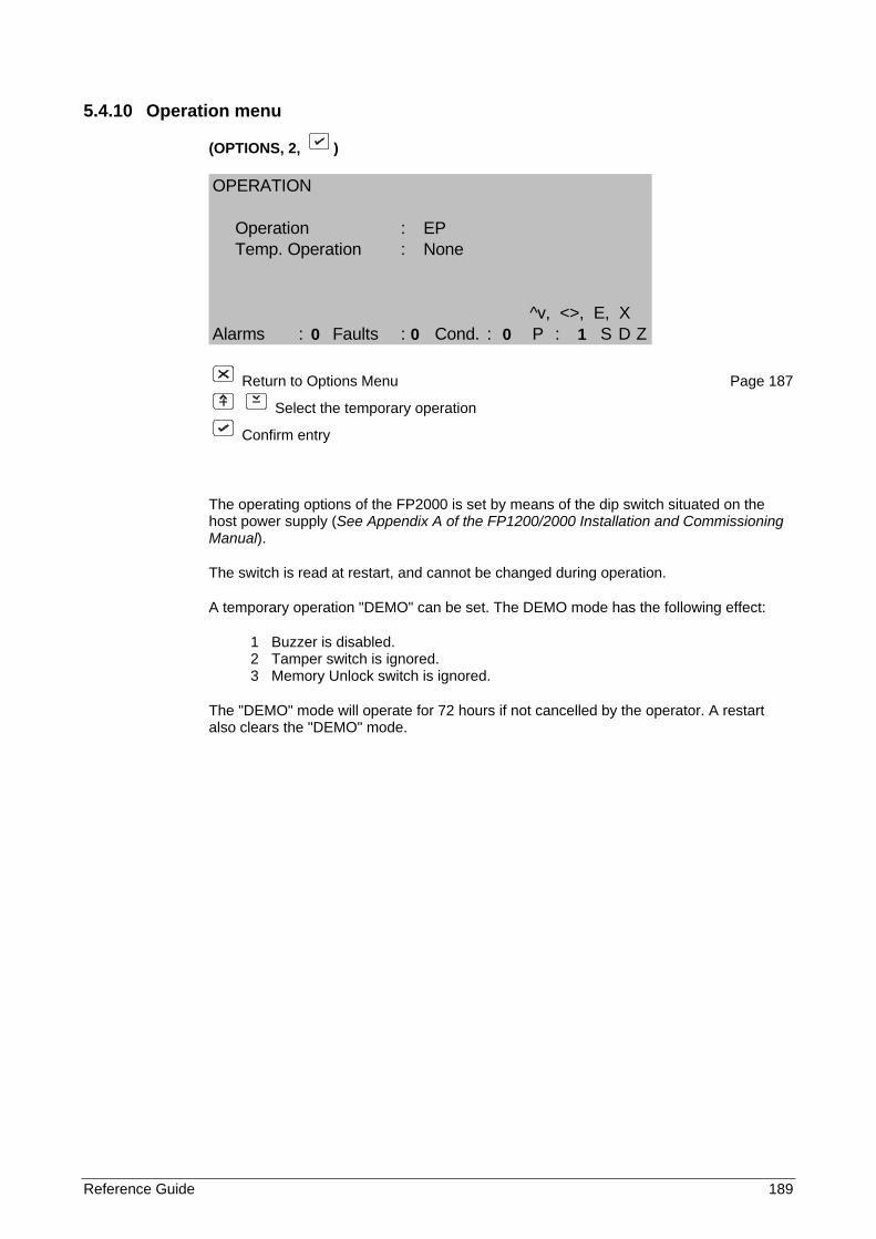
Reference Guide 189
5.4.10 Operation menu
(OPTIONS, 2, )
OPERATION
Operation : EPTemp. Operation : None
^v, <>, E, XAlarms : Faults : Cond. : P : S D Z
Return to Options Menu Page 187
Select the temporary operation
Confirm entry
The operating options of the FP2000 is set by means of the dip switch situated on the host power supply (See Appendix A of the FP1200/2000 Installation and Commissioning Manual).
The switch is read at restart, and cannot be changed during operation.
A temporary operation "DEMO" can be set. The DEMO mode has the following effect:
1 Buzzer is disabled. 2 Tamper switch is ignored. 3 Memory Unlock switch is ignored.
The "DEMO" mode will operate for 72 hours if not cancelled by the operator. A restart also clears the "DEMO" mode.
0 0 0 1
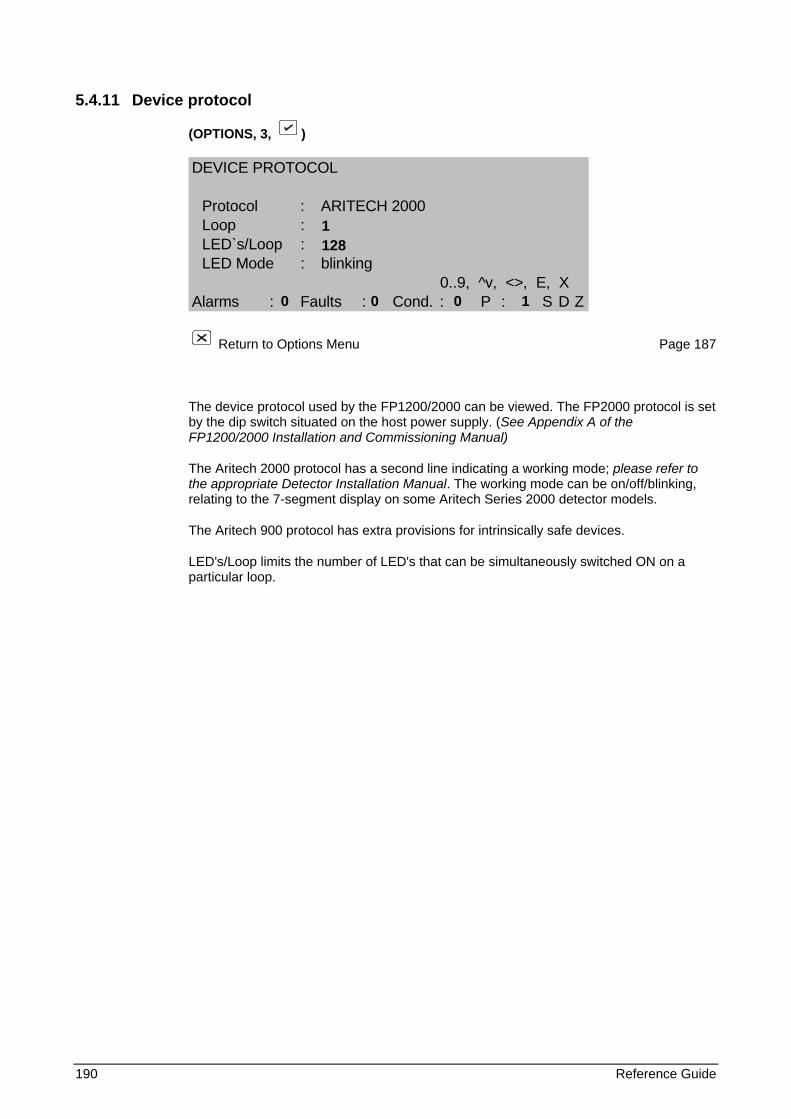
190 Reference Guide
5.4.11 Device protocol
(OPTIONS, 3, )
DEVICE PROTOCOL
Protocol : ARITECH 2000Loop :LED`s/Loop :LED Mode : blinking
0..9, ^v, <>, E, XAlarms : Faults : Cond. : P : S D Z
Return to Options Menu Page 187
The device protocol used by the FP1200/2000 can be viewed. The FP2000 protocol is set by the dip switch situated on the host power supply. (See Appendix A of the FP1200/2000 Installation and Commissioning Manual)
The Aritech 2000 protocol has a second line indicating a working mode; please refer to the appropriate Detector Installation Manual. The working mode can be on/off/blinking, relating to the 7-segment display on some Aritech Series 2000 detector models.
The Aritech 900 protocol has extra provisions for intrinsically safe devices.
LED's/Loop limits the number of LED's that can be simultaneously switched ON on a particular loop.
1 128
0 0 0 1
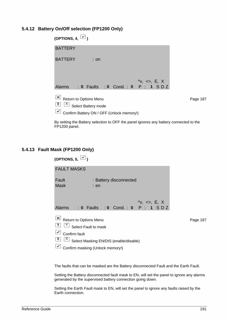
Reference Guide 191
5.4.12 Battery On/Off selection (FP1200 Only)
(OPTIONS, 4, )
BATTERY
BATTERY : on
^v, <>, E, XAlarms : Faults : Cond. : P : S D Z
Return to Options Menu Page 187
Select Battery mode
Confirm Battery ON / OFF (Unlock memory!)
By setting the Battery selection to OFF the panel ignores any battery connected to the FP1200 panel.
5.4.13 Fault Mask (FP1200 Only)
(OPTIONS, 5, )
FAULT MASKS
Fault : Battery disconnectedMask : en
^v, <>, E, XAlarms : Faults : Cond. : P : S D Z
Return to Options Menu Page 187
Select Fault to mask
Confirm fault
Select Masking EN/DIS (enable/disable)
Confirm masking (Unlock memory!)
The faults that can be masked are the Battery disconnected Fault and the Earth Fault.
Setting the Battery disconnected fault mask to EN, will set the panel to ignore any alarms generated by the supervised battery connection going down.
Setting the Earth Fault mask to EN, will set the panel to ignore any faults raised by the Earth connection.
0 0 0 1
0 0 0 1
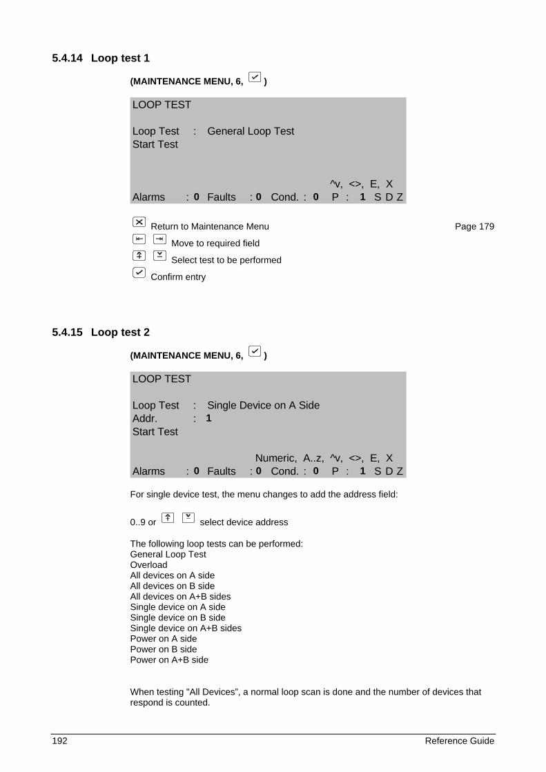
192 Reference Guide
5.4.14 Loop test 1
(MAINTENANCE MENU, 6, )
LOOP TEST
Loop Test : General Loop TestStart Test
^v, <>, E, XAlarms : Faults : Cond. : P : S D Z
Return to Maintenance Menu Page 179
Move to required field
Select test to be performed
Confirm entry
5.4.15 Loop test 2
(MAINTENANCE MENU, 6, )
LOOP TEST
Loop Test : Single Device on A SideAddr. :Start Test
Numeric, A..z, ^v, <>, E, XAlarms : Faults : Cond. : P : S D Z
For single device test, the menu changes to add the address field:
0..9 or select device address
The following loop tests can be performed: General Loop Test Overload All devices on A side All devices on B side All devices on A+B sides Single device on A side Single device on B side Single device on A+B sides Power on A side Power on B side Power on A+B side
When testing "All Devices”, a normal loop scan is done and the number of devices that respond is counted.
0 0 0 1
1 0 0 0 1

Reference Guide 193
The General Loop Test includes:
• All devices on A side
• All devices on B side
• All devices on A+B sides
• Overloads
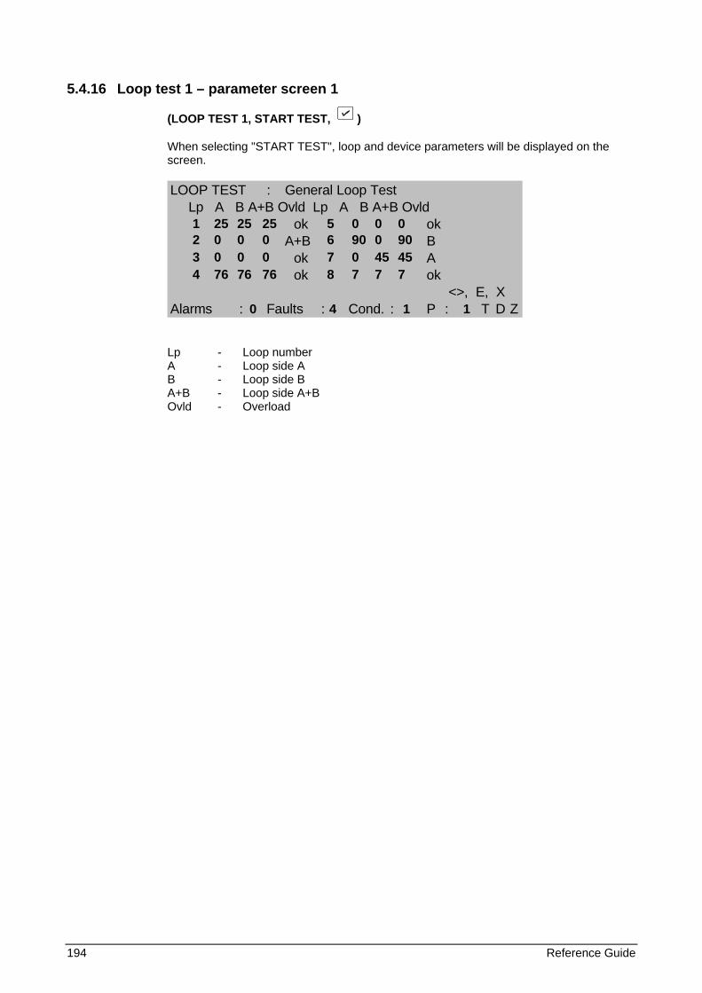
194 Reference Guide
5.4.16 Loop test 1 – parameter screen 1
(LOOP TEST 1, START TEST, )
When selecting "START TEST", loop and device parameters will be displayed on the screen.
LOOP TEST : General Loop TestLp A B A+B Ovld Lp A B A+B Ovld
ok okA+B B
ok Aok ok
<>, E, XAlarms : Faults : Cond. : P : T D Z
Lp - Loop number A - Loop side A B - Loop side B A+B - Loop side A+B Ovld - Overload
1 25 25 25 5 0 0 0 2 0 0 0 6 90 0 90 3 0 0 0 7 0 45 45 4 76 76 76 8 7 7 7
0 4 1 1
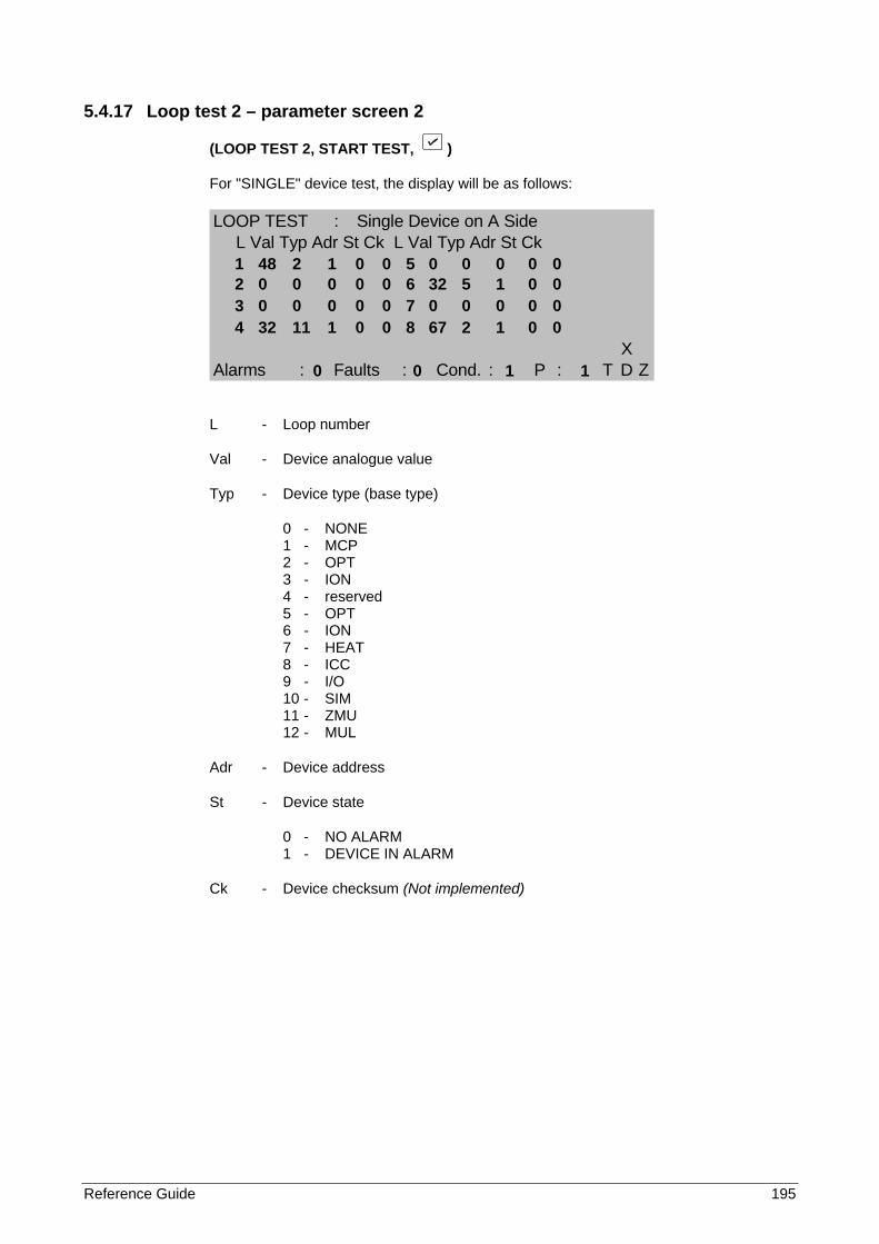
Reference Guide 195
5.4.17 Loop test 2 – parameter screen 2
(LOOP TEST 2, START TEST, )
For "SINGLE" device test, the display will be as follows:
LOOP TEST : Single Device on A SideL Val Typ Adr St Ck L Val Typ Adr St Ck
XAlarms : Faults : Cond. : P : T D Z
L - Loop number
Val - Device analogue value
Typ - Device type (base type)
0 - NONE 1 - MCP 2 - OPT 3 - ION 4 - reserved 5 - OPT 6 - ION 7 - HEAT 8 - ICC 9 - I/O 10 - SIM 11 - ZMU 12 - MUL
Adr - Device address
St - Device state
0 - NO ALARM 1 - DEVICE IN ALARM
Ck - Device checksum (Not implemented)
1 48 2 1 0 0 5 0 0 0 0 0 2 0 0 0 0 0 6 32 5 1 0 0 3 0 0 0 0 0 7 0 0 0 0 0 4 32 11 1 0 0 8 67 2 1 0 0
0 0 1 1
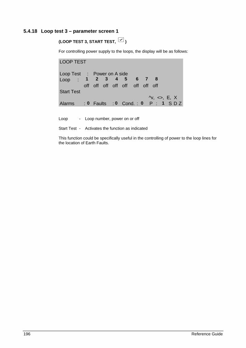
196 Reference Guide
5.4.18 Loop test 3 – parameter screen 1
(LOOP TEST 3, START TEST, )
For controlling power supply to the loops, the display will be as follows:
LOOP TEST
Loop Test : Power on A sideLoop :
off off off off off off off offStart Test
^v, <>, E, XAlarms : Faults : Cond. : P : S D Z
Loop - Loop number, power on or off
Start Test - Activates the function as indicated
This function could be specifically useful in the controlling of power to the loop lines for the location of Earth Faults.
1 2 3 4 5 6 7 8
0 0 0 1

Reference Guide 197
5.4.19 Fast Compensation
(MAINTENANCE MENU, 7, )
Returns Automatically to Maintenance Menu Page 179
This function will allow the panel to use a fast compensation algorithm to compensate quickly according to the current analogue values of the smoke detectors. It may be particularly useful in the event of clearing all device statistics when there may already be devices that are highly compensated. With no compensation applied, these devices may be very sensitive and prone to nuisance alarms.
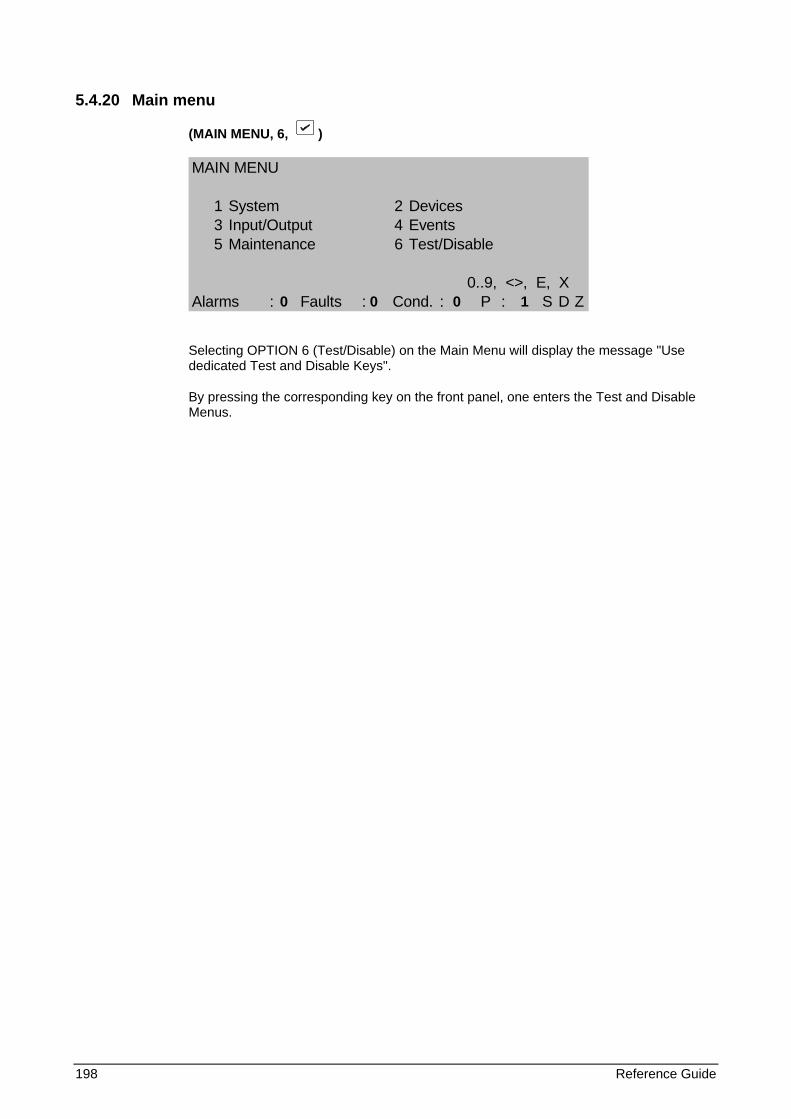
198 Reference Guide
5.4.20 Main menu
(MAIN MENU, 6, )
MAIN MENU
1 System 2 Devices3 Input/Output 4 Events5 Maintenance 6 Test/Disable
0..9, <>, E, XAlarms : Faults : Cond. : P : S D Z
Selecting OPTION 6 (Test/Disable) on the Main Menu will display the message "Use dedicated Test and Disable Keys".
By pressing the corresponding key on the front panel, one enters the Test and Disable Menus.
0 0 0 1
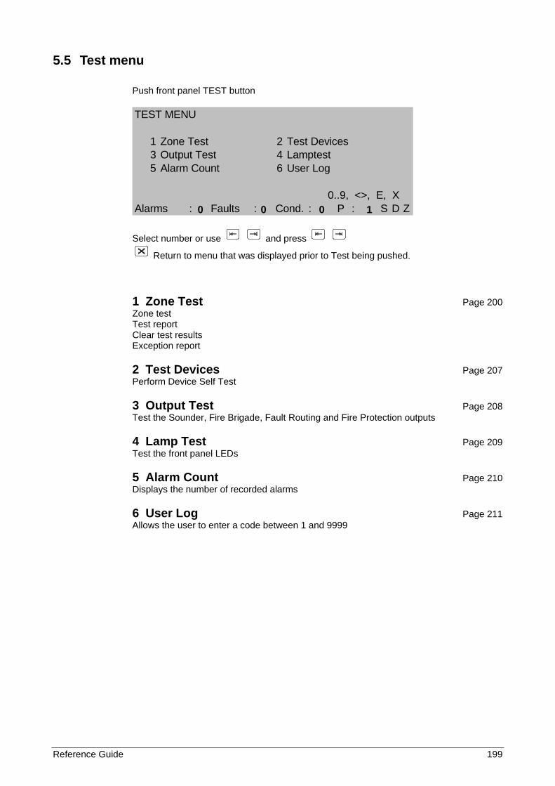
Reference Guide 199
5.5 Test menu
Push front panel TEST button
TEST MENU
1 Zone Test 2 Test Devices3 Output Test 4 Lamptest5 Alarm Count 6 User Log
0..9, <>, E, XAlarms : Faults : Cond. : P : S D Z
Select number or use and press
Return to menu that was displayed prior to Test being pushed.
1 Zone Test Page 200 Zone test Test report Clear test results Exception report
2 Test Devices Page 207 Perform Device Self Test
3 Output Test Page 208 Test the Sounder, Fire Brigade, Fault Routing and Fire Protection outputs
4 Lamp Test Page 209 Test the front panel LEDs
5 Alarm Count Page 210 Displays the number of recorded alarms
6 User Log Page 211 Allows the user to enter a code between 1 and 9999
0 0 0 1
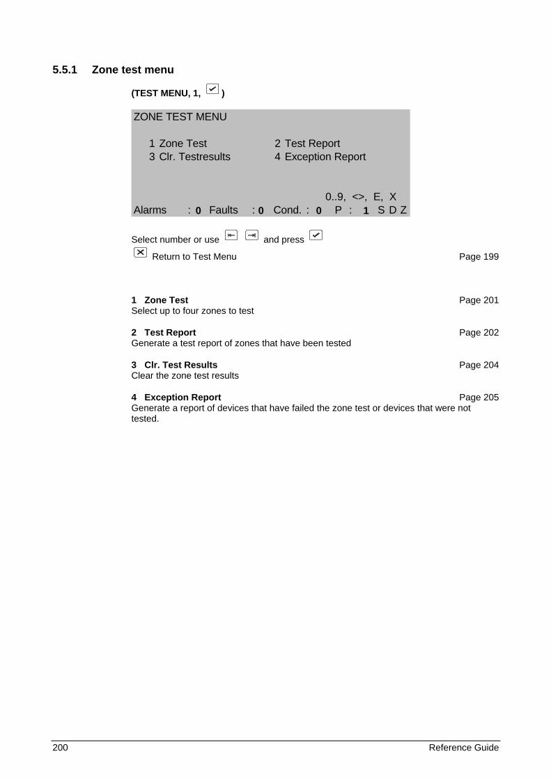
200 Reference Guide
5.5.1 Zone test menu
(TEST MENU, 1, )
ZONE TEST MENU
1 Zone Test 2 Test Report3 Clr. Testresults 4 Exception Report
0..9, <>, E, XAlarms : Faults : Cond. : P : S D Z
Select number or use and press
Return to Test Menu Page 199
1 Zone Test Page 201 Select up to four zones to test
2 Test Report Page 202 Generate a test report of zones that have been tested
3 Clr. Test Results Page 204 Clear the zone test results
4 Exception Report Page 205 Generate a report of devices that have failed the zone test or devices that were not tested.
0 0 0 1
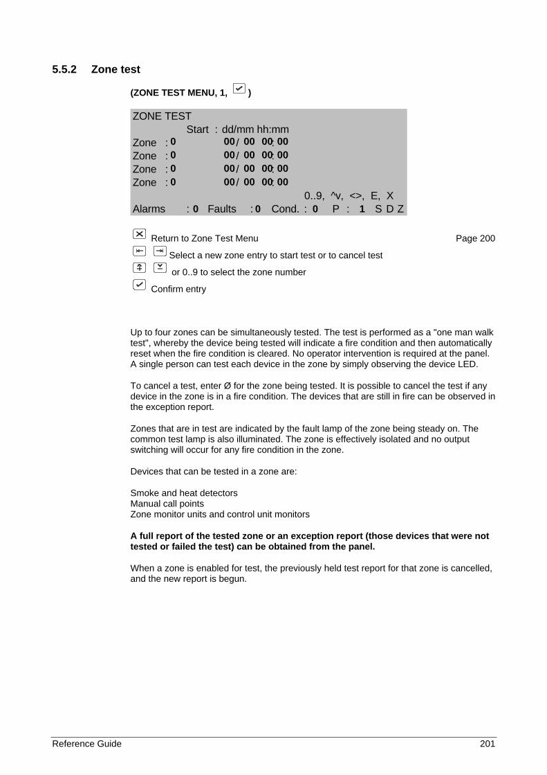
Reference Guide 201
5.5.2 Zone test
(ZONE TEST MENU, 1, )
ZONE TESTStart : dd/mm hh:mm
Zone : / :Zone : / :Zone : / :Zone : / :
0..9, ^v, <>, E, XAlarms : Faults : Cond. : P : S D Z
Return to Zone Test Menu Page 200
Select a new zone entry to start test or to cancel test
or 0..9 to select the zone number
Confirm entry
Up to four zones can be simultaneously tested. The test is performed as a "one man walk test", whereby the device being tested will indicate a fire condition and then automatically reset when the fire condition is cleared. No operator intervention is required at the panel. A single person can test each device in the zone by simply observing the device LED.
To cancel a test, enter Ø for the zone being tested. It is possible to cancel the test if any device in the zone is in a fire condition. The devices that are still in fire can be observed in the exception report.
Zones that are in test are indicated by the fault lamp of the zone being steady on. The common test lamp is also illuminated. The zone is effectively isolated and no output switching will occur for any fire condition in the zone.
Devices that can be tested in a zone are:
Smoke and heat detectors Manual call points Zone monitor units and control unit monitors
A full report of the tested zone or an exception report (those devices that were not tested or failed the test) can be obtained from the panel.
When a zone is enabled for test, the previously held test report for that zone is cancelled, and the new report is begun.
0 00 00 00 00 0 00 00 00 00 0 00 00 00 00 0 00 00 00 00 0 0 0 1
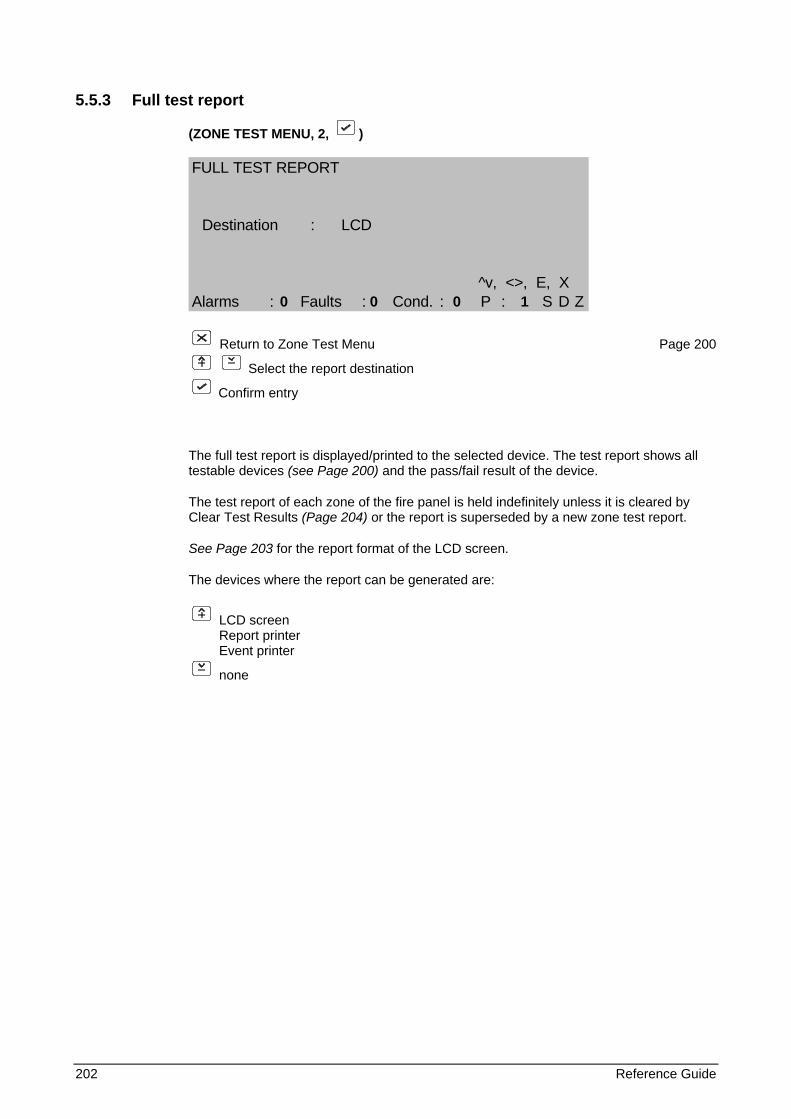
202 Reference Guide
5.5.3 Full test report
(ZONE TEST MENU, 2, )
FULL TEST REPORT
Destination : LCD
^v, <>, E, XAlarms : Faults : Cond. : P : S D Z
Return to Zone Test Menu Page 200
Select the report destination
Confirm entry
The full test report is displayed/printed to the selected device. The test report shows all testable devices (see Page 200) and the pass/fail result of the device.
The test report of each zone of the fire panel is held indefinitely unless it is cleared by Clear Test Results (Page 204) or the report is superseded by a new zone test report.
See Page 203 for the report format of the LCD screen.
The devices where the report can be generated are:
LCD screen Report printer Event printer
none
0 0 0 1
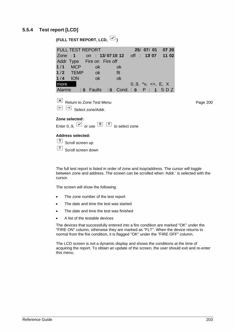
Reference Guide 203
5.5.4 Test report [LCD]
(FULL TEST REPORT, LCD, )
FULL TEST REPORT / / :Zone : on : / : off : / :Addr Type Fire on Fire off
/ MCP ok ok/ TEMP ok flt/ ION ok ok
more 0..9, ^v, <>, E, XAlarms : Faults : Cond. : P : S D Z
Return to Zone Test Menu Page 200
Select zone/Addr.
Zone selected:
Enter 0..9, or use to select zone
Address selected:
Scroll screen up
Scroll screen down
The full test report is listed in order of zone and loop/address. The cursor will toggle between zone and address. The screen can be scrolled when ‘Addr.’ is selected with the cursor.
The screen will show the following:
• The zone number of the test report
• The date and time the test was started
• The date and time the test was finished
• A list of the testable devices
The devices that successfully entered into a fire condition are marked "OK" under the "FIRE ON" column, otherwise they are marked as "FLT". When the device returns to normal from the fire condition, it is flagged "OK" under the "FIRE OFF" column.
The LCD screen is not a dynamic display and shows the conditions at the time of acquiring the report. To obtain an update of the screen, the user should exit and re-enter this menu.
25 07 01 07 20 1 13 07 10 12 13 07 11 02 1 1 1 2 1 4 0 0 0 1
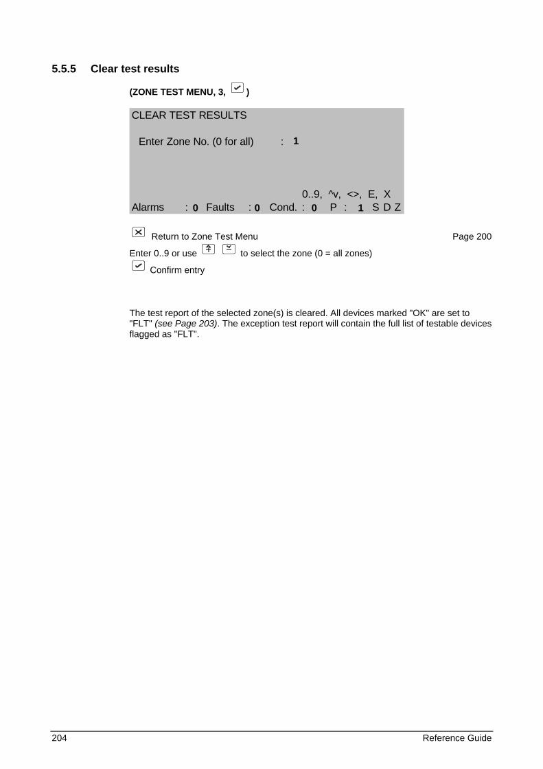
204 Reference Guide
5.5.5 Clear test results
(ZONE TEST MENU, 3, )
CLEAR TEST RESULTS
Enter Zone No. (0 for all) :
0..9, ^v, <>, E, XAlarms : Faults : Cond. : P : S D Z
Return to Zone Test Menu Page 200
Enter 0..9 or use to select the zone (0 = all zones)
Confirm entry
The test report of the selected zone(s) is cleared. All devices marked "OK" are set to "FLT" (see Page 203). The exception test report will contain the full list of testable devices flagged as "FLT".
1 0 0 0 1
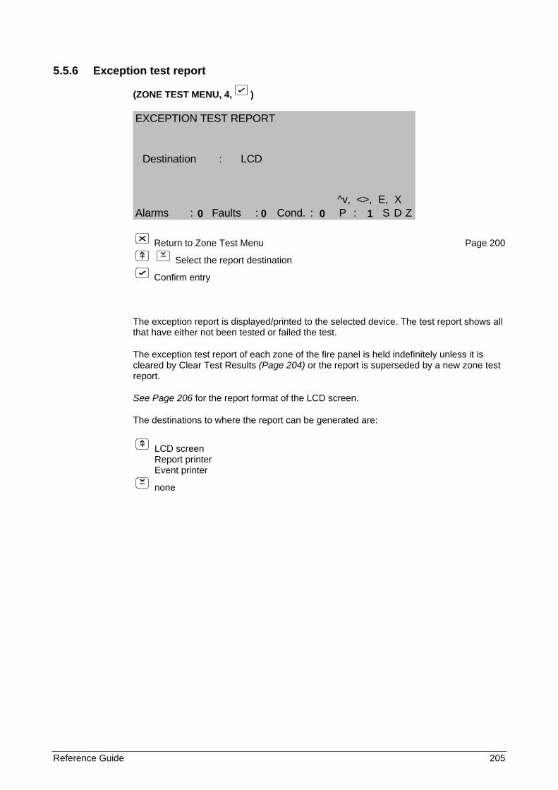
Reference Guide 205
5.5.6 Exception test report
(ZONE TEST MENU, 4, )
EXCEPTION TEST REPORT
Destination : LCD
^v, <>, E, XAlarms : Faults : Cond. : P : S D Z
Return to Zone Test Menu Page 200
Select the report destination
Confirm entry
The exception report is displayed/printed to the selected device. The test report shows all that have either not been tested or failed the test.
The exception test report of each zone of the fire panel is held indefinitely unless it is cleared by Clear Test Results (Page 204) or the report is superseded by a new zone test report.
See Page 206 for the report format of the LCD screen.
The destinations to where the report can be generated are:
LCD screen Report printer Event printer
none
0 0 0 1
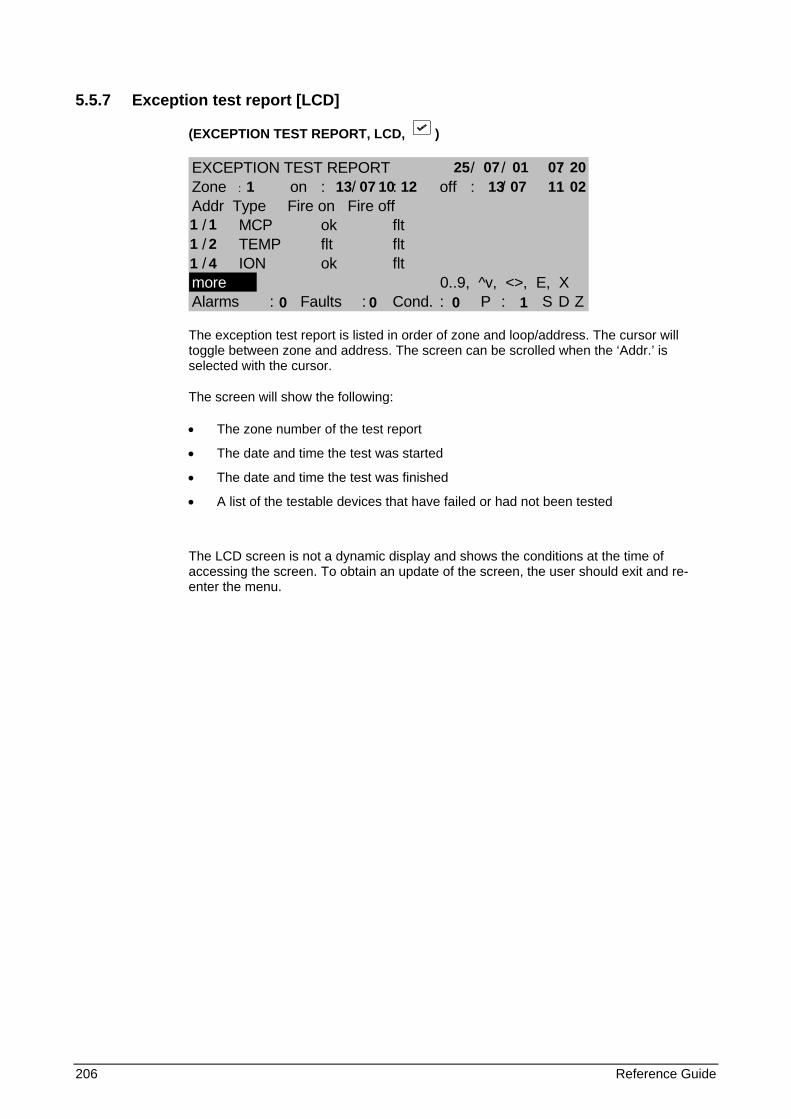
206 Reference Guide
5.5.7 Exception test report [LCD]
(EXCEPTION TEST REPORT, LCD, )
EXCEPTION TEST REPORT / / :Zone : on : / : off : / :Addr Type Fire on Fire off
/ MCP ok flt/ TEMP flt flt/ ION ok flt
more 0..9, ^v, <>, E, XAlarms : Faults : Cond. : P : S D Z
The exception test report is listed in order of zone and loop/address. The cursor will toggle between zone and address. The screen can be scrolled when the ‘Addr.’ is selected with the cursor.
The screen will show the following:
• The zone number of the test report
• The date and time the test was started
• The date and time the test was finished
• A list of the testable devices that have failed or had not been tested
The LCD screen is not a dynamic display and shows the conditions at the time of accessing the screen. To obtain an update of the screen, the user should exit and re-enter the menu.
25 07 01 07 20 1 13 07 10 12 13 07 11 02 1 1 1 2 1 4 0 0 0 1
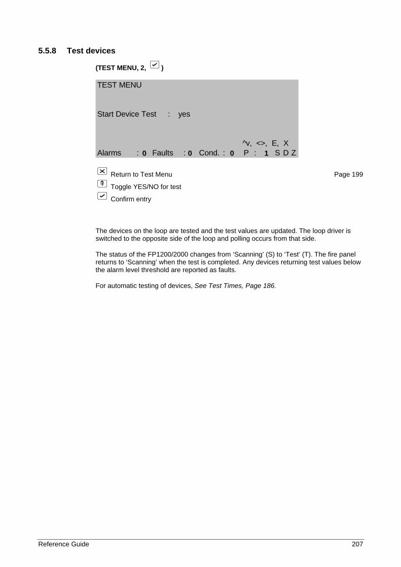
Reference Guide 207
5.5.8 Test devices
(TEST MENU, 2, )
TEST MENU
Start Device Test : yes
^v, <>, E, XAlarms : Faults : Cond. : P : S D Z
Return to Test Menu Page 199
Toggle YES/NO for test
Confirm entry
The devices on the loop are tested and the test values are updated. The loop driver is switched to the opposite side of the loop and polling occurs from that side.
The status of the FP1200/2000 changes from ‘Scanning’ (S) to ‘Test’ (T). The fire panel returns to ‘Scanning’ when the test is completed. Any devices returning test values below the alarm level threshold are reported as faults.
For automatic testing of devices, See Test Times, Page 186.
0 0 0 1
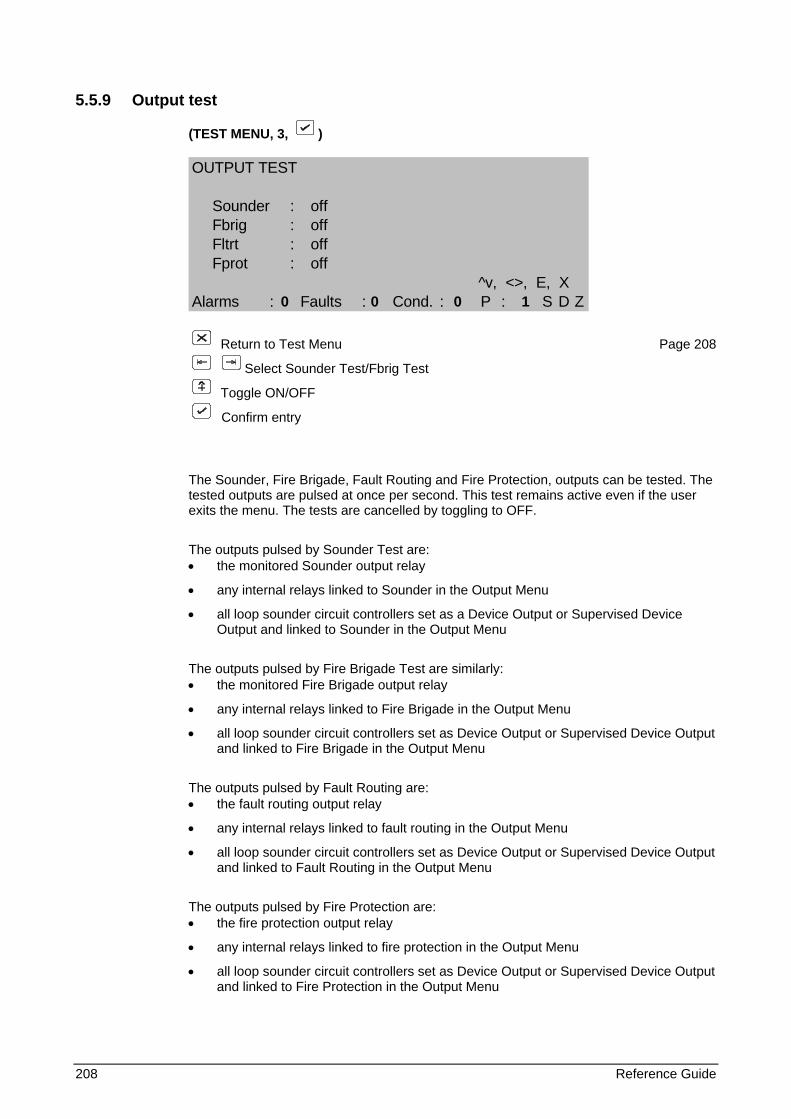
208 Reference Guide
5.5.9 Output test
(TEST MENU, 3, )
OUTPUT TEST
Sounder : offFbrig : offFltrt : offFprot : off
^v, <>, E, XAlarms : Faults : Cond. : P : S D Z
Return to Test Menu Page 208
Select Sounder Test/Fbrig Test
Toggle ON/OFF
Confirm entry
The Sounder, Fire Brigade, Fault Routing and Fire Protection, outputs can be tested. The tested outputs are pulsed at once per second. This test remains active even if the user exits the menu. The tests are cancelled by toggling to OFF.
The outputs pulsed by Sounder Test are: • the monitored Sounder output relay
• any internal relays linked to Sounder in the Output Menu
• all loop sounder circuit controllers set as a Device Output or Supervised Device Output and linked to Sounder in the Output Menu
The outputs pulsed by Fire Brigade Test are similarly: • the monitored Fire Brigade output relay
• any internal relays linked to Fire Brigade in the Output Menu
• all loop sounder circuit controllers set as Device Output or Supervised Device Output and linked to Fire Brigade in the Output Menu
The outputs pulsed by Fault Routing are: • the fault routing output relay
• any internal relays linked to fault routing in the Output Menu
• all loop sounder circuit controllers set as Device Output or Supervised Device Output and linked to Fault Routing in the Output Menu
The outputs pulsed by Fire Protection are: • the fire protection output relay
• any internal relays linked to fire protection in the Output Menu
• all loop sounder circuit controllers set as Device Output or Supervised Device Output and linked to Fire Protection in the Output Menu
0 0 0 1

Reference Guide 209
5.5.10 Lamp test
TEST MENU, 4, )
The LED lamps of the front panel are illuminated. The lamps are illuminated in blocks where each block is tested for one second.
Each time the button is pushed, the test is repeated.
The "Test 3rd Source" LED will not go on during Lamp Test, it has to be tested separately by means of pushing the appropriate button.
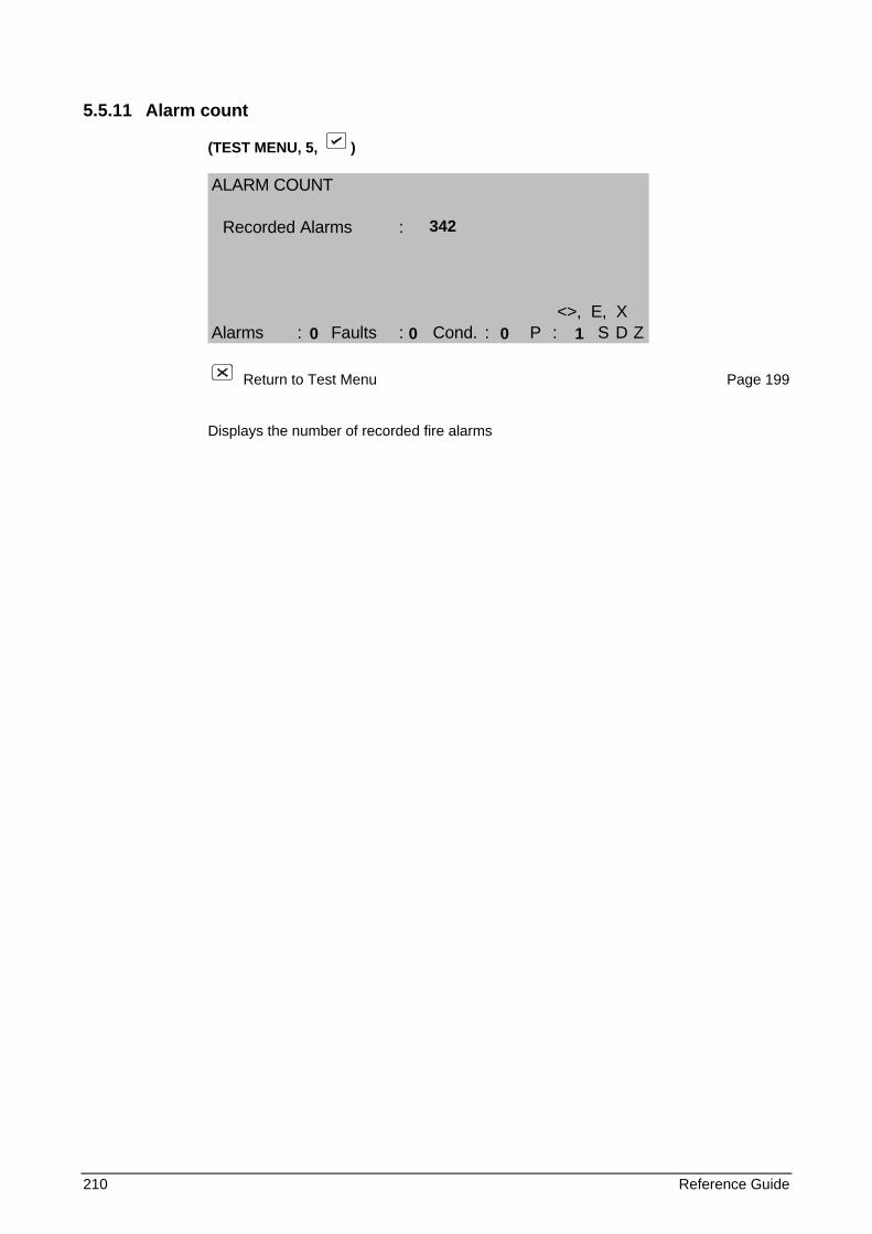
210 Reference Guide
5.5.11 Alarm count
(TEST MENU, 5, )
ALARM COUNT
Recorded Alarms :
<>, E, XAlarms : Faults : Cond. : P : S D Z
Return to Test Menu Page 199
Displays the number of recorded fire alarms
342 0 0 0 1
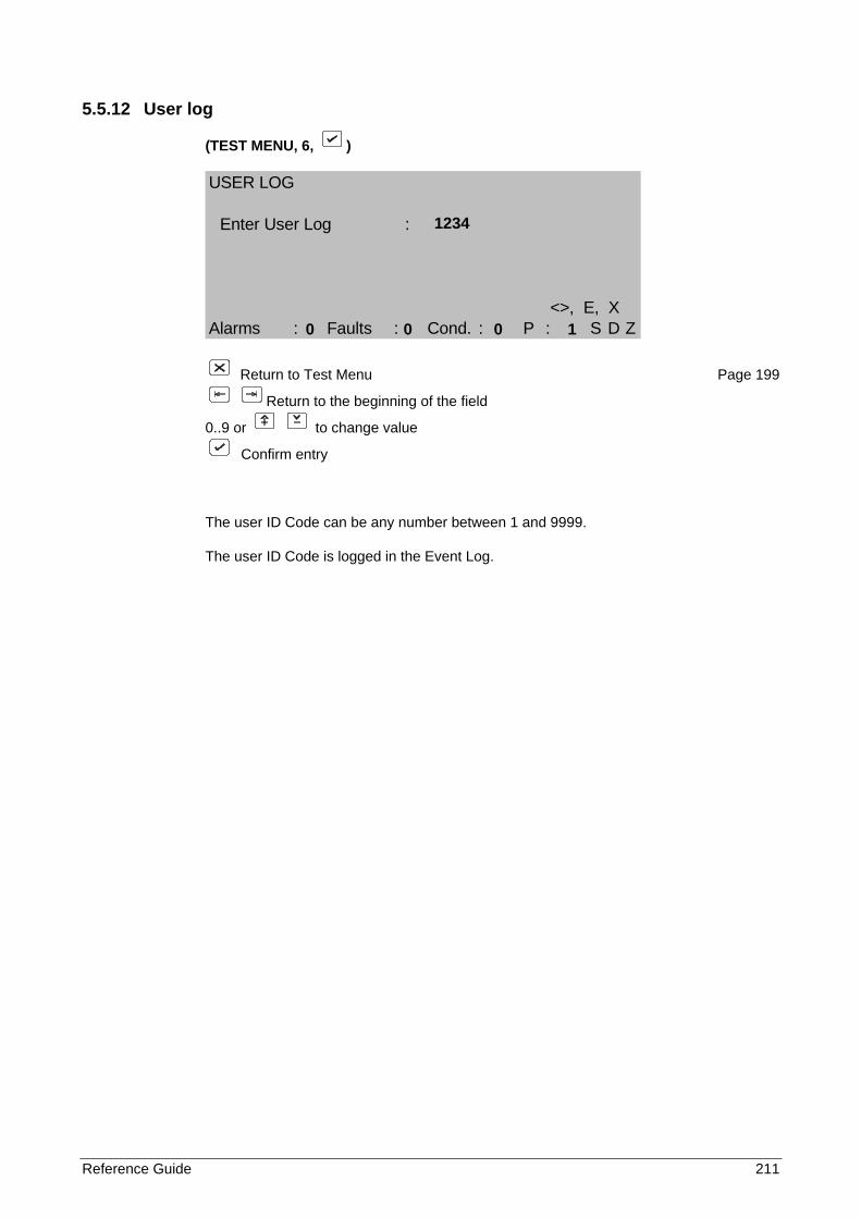
Reference Guide 211
5.5.12 User log
(TEST MENU, 6, )
USER LOG
Enter User Log :
<>, E, XAlarms : Faults : Cond. : P : S D Z
Return to Test Menu Page 199
Return to the beginning of the field
0..9 or to change value
Confirm entry
The user ID Code can be any number between 1 and 9999.
The user ID Code is logged in the Event Log.
1234 0 0 0 1
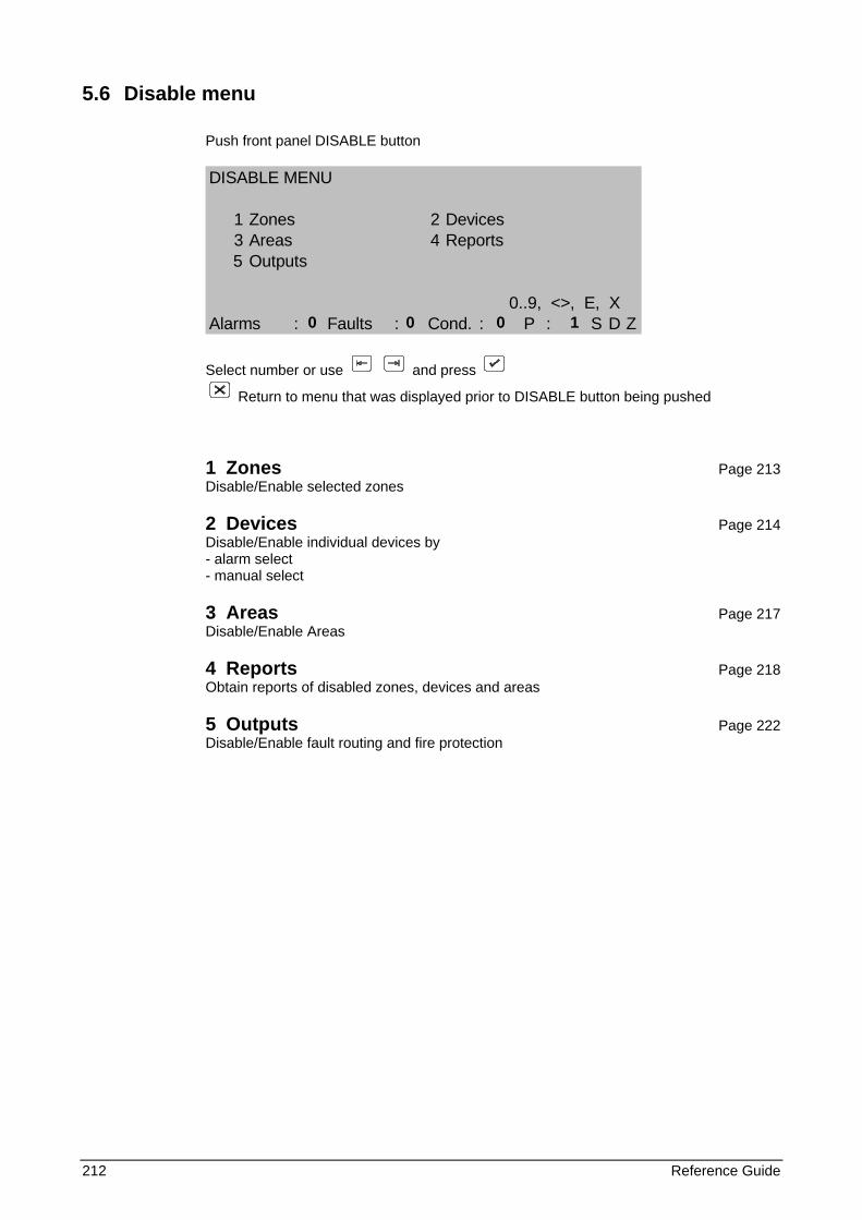
212 Reference Guide
5.6 Disable menu
Push front panel DISABLE button
DISABLE MENU
1 Zones 2 Devices3 Areas 4 Reports5 Outputs
0..9, <>, E, XAlarms : Faults : Cond. : P : S D Z
Select number or use and press
Return to menu that was displayed prior to DISABLE button being pushed
1 Zones Page 213 Disable/Enable selected zones
2 Devices Page 214 Disable/Enable individual devices by - alarm select - manual select
3 Areas Page 217 Disable/Enable Areas
4 Reports Page 218 Obtain reports of disabled zones, devices and areas
5 Outputs Page 222 Disable/Enable fault routing and fire protection
0 0 0 1
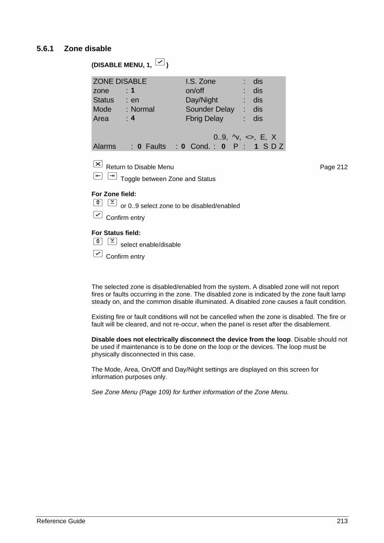
Reference Guide 213
5.6.1 Zone disable
(DISABLE MENU, 1, )
ZONE DISABLE I.S. Zone : diszone : on/off : disStatus : en Day/Night : disMode : Normal Sounder Delay : disArea : Fbrig Delay : dis
0..9, ^v, <>, E, XAlarms : Faults : Cond. : P : S D Z
Return to Disable Menu Page 212
Toggle between Zone and Status
For Zone field:
or 0..9 select zone to be disabled/enabled
Confirm entry
For Status field:
select enable/disable
Confirm entry
The selected zone is disabled/enabled from the system. A disabled zone will not report fires or faults occurring in the zone. The disabled zone is indicated by the zone fault lamp steady on, and the common disable illuminated. A disabled zone causes a fault condition.
Existing fire or fault conditions will not be cancelled when the zone is disabled. The fire or fault will be cleared, and not re-occur, when the panel is reset after the disablement.
Disable does not electrically disconnect the device from the loop. Disable should not be used if maintenance is to be done on the loop or the devices. The loop must be physically disconnected in this case.
The Mode, Area, On/Off and Day/Night settings are displayed on this screen for information purposes only.
See Zone Menu (Page 109) for further information of the Zone Menu.
1 4 0 0 0 1
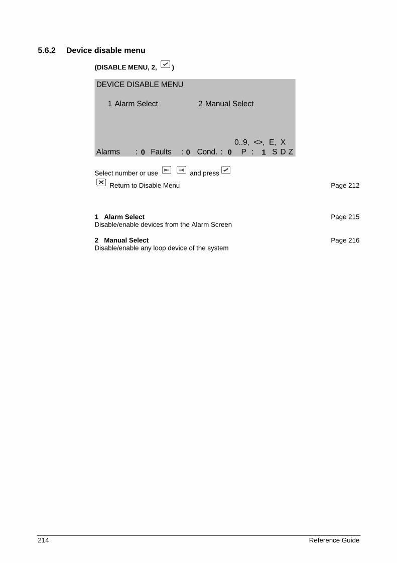
214 Reference Guide
5.6.2 Device disable menu
(DISABLE MENU, 2, )
DEVICE DISABLE MENU
1 Alarm Select 2 Manual Select
0..9, <>, E, XAlarms : Faults : Cond. : P : S D Z
Select number or use and press
Return to Disable Menu Page 212
1 Alarm Select Page 215 Disable/enable devices from the Alarm Screen
2 Manual Select Page 216 Disable/enable any loop device of the system
0 0 0 1
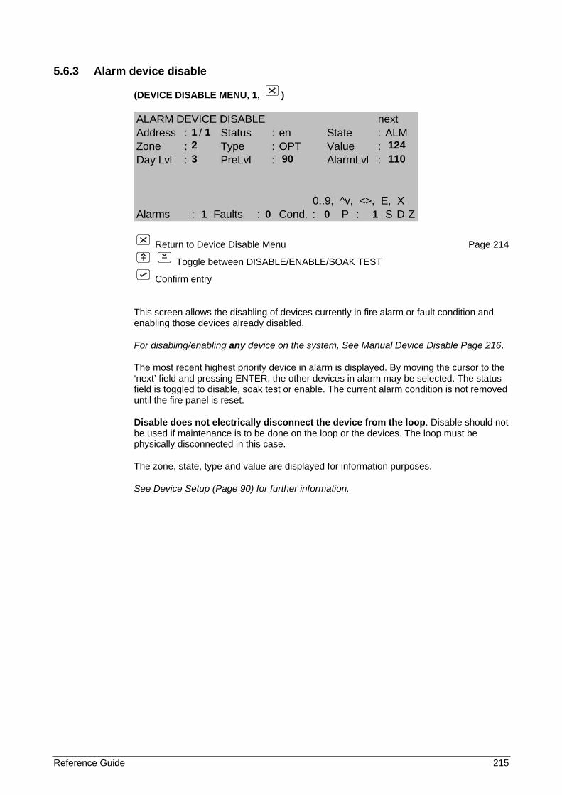
Reference Guide 215
5.6.3 Alarm device disable
(DEVICE DISABLE MENU, 1, )
ALARM DEVICE DISABLE nextAddress : / Status : en State : ALMZone : Type : OPT Value :Day Lvl : PreLvl : AlarmLvl :
0..9, ^v, <>, E, XAlarms : Faults : Cond. : P : S D Z
Return to Device Disable Menu Page 214
Toggle between DISABLE/ENABLE/SOAK TEST
Confirm entry
This screen allows the disabling of devices currently in fire alarm or fault condition and enabling those devices already disabled.
For disabling/enabling any device on the system, See Manual Device Disable Page 216.
The most recent highest priority device in alarm is displayed. By moving the cursor to the ‘next’ field and pressing ENTER, the other devices in alarm may be selected. The status field is toggled to disable, soak test or enable. The current alarm condition is not removed until the fire panel is reset.
Disable does not electrically disconnect the device from the loop. Disable should not be used if maintenance is to be done on the loop or the devices. The loop must be physically disconnected in this case.
The zone, state, type and value are displayed for information purposes.
See Device Setup (Page 90) for further information.
1 1 2 124 3 90 110 1 0 0 1
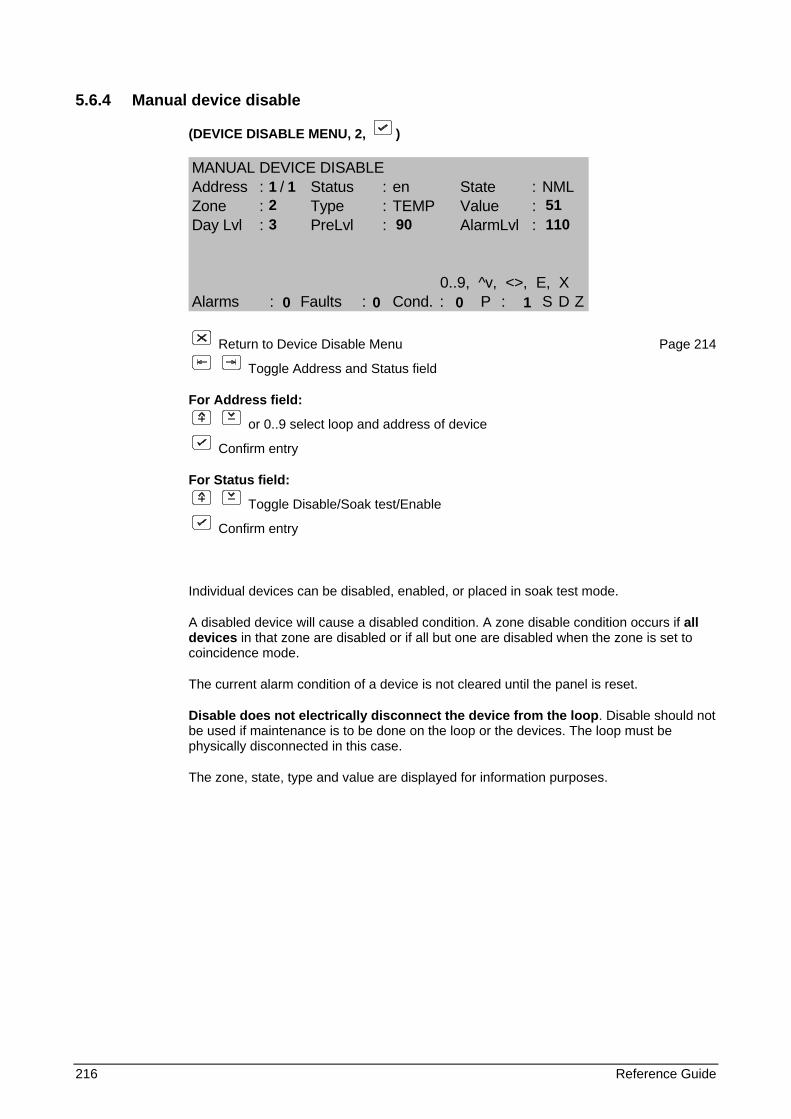
216 Reference Guide
5.6.4 Manual device disable
(DEVICE DISABLE MENU, 2, )
MANUAL DEVICE DISABLEAddress : / Status : en State : NMLZone : Type : TEMP Value :Day Lvl : PreLvl : AlarmLvl :
0..9, ^v, <>, E, XAlarms : Faults : Cond. : P : S D Z
Return to Device Disable Menu Page 214
Toggle Address and Status field
For Address field:
or 0..9 select loop and address of device
Confirm entry
For Status field:
Toggle Disable/Soak test/Enable
Confirm entry
Individual devices can be disabled, enabled, or placed in soak test mode.
A disabled device will cause a disabled condition. A zone disable condition occurs if all devices in that zone are disabled or if all but one are disabled when the zone is set to coincidence mode.
The current alarm condition of a device is not cleared until the panel is reset.
Disable does not electrically disconnect the device from the loop. Disable should not be used if maintenance is to be done on the loop or the devices. The loop must be physically disconnected in this case.
The zone, state, type and value are displayed for information purposes.
1 1 2 51 3 90 110 0 0 0 1
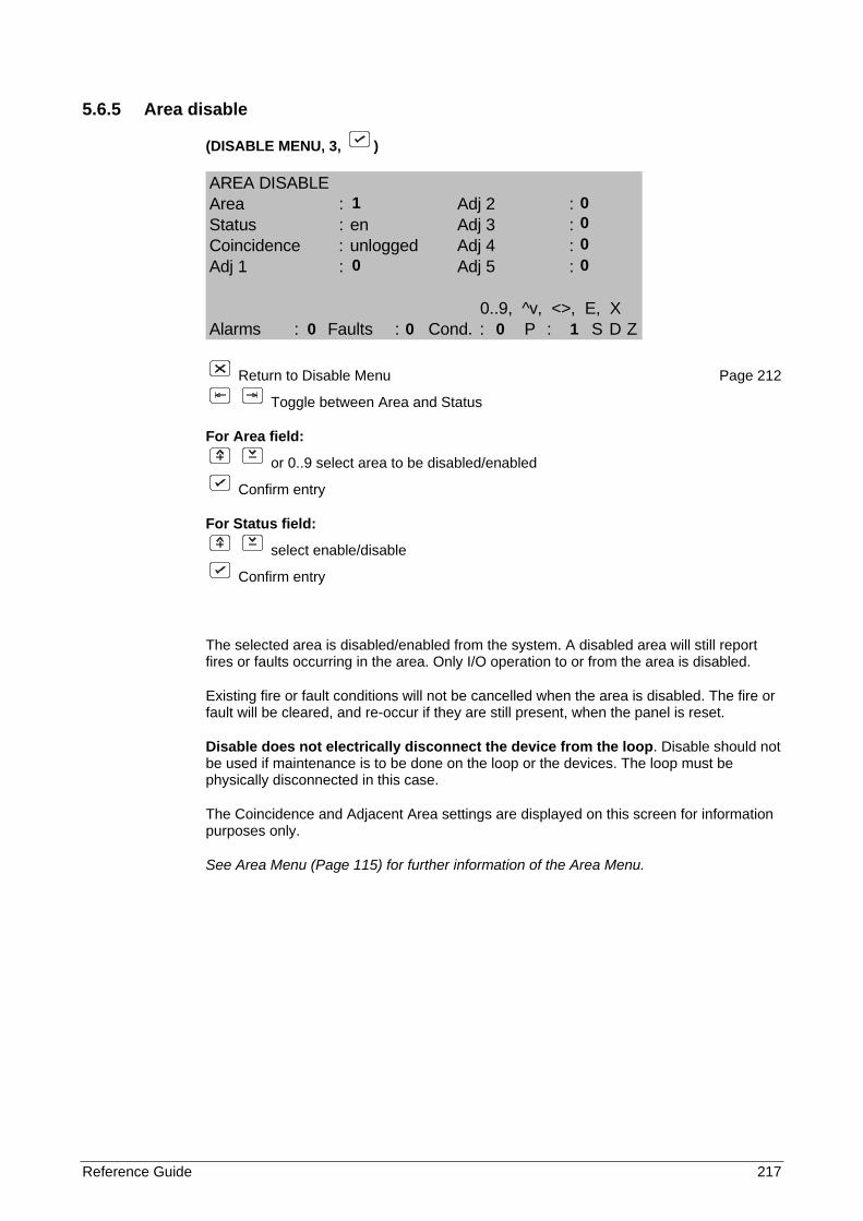
Reference Guide 217
5.6.5 Area disable
(DISABLE MENU, 3, )
AREA DISABLEArea : Adj 2 :Status : en Adj 3 :Coincidence : unlogged Adj 4 :Adj 1 : Adj 5 :
0..9, ^v, <>, E, XAlarms : Faults : Cond. : P : S D Z
Return to Disable Menu Page 212
Toggle between Area and Status
For Area field:
or 0..9 select area to be disabled/enabled
Confirm entry
For Status field:
select enable/disable
Confirm entry
The selected area is disabled/enabled from the system. A disabled area will still report fires or faults occurring in the area. Only I/O operation to or from the area is disabled.
Existing fire or fault conditions will not be cancelled when the area is disabled. The fire or fault will be cleared, and re-occur if they are still present, when the panel is reset.
Disable does not electrically disconnect the device from the loop. Disable should not be used if maintenance is to be done on the loop or the devices. The loop must be physically disconnected in this case.
The Coincidence and Adjacent Area settings are displayed on this screen for information purposes only.
See Area Menu (Page 115) for further information of the Area Menu.
1 0 0 0 0 0 0 0 0 1
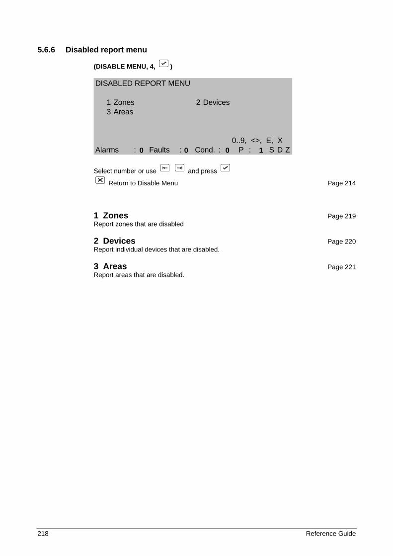
218 Reference Guide
5.6.6 Disabled report menu
(DISABLE MENU, 4, )
DISABLED REPORT MENU
1 Zones 2 Devices3 Areas
0..9, <>, E, XAlarms : Faults : Cond. : P : S D Z
Select number or use and press
Return to Disable Menu Page 214
1 Zones Page 219 Report zones that are disabled
2 Devices Page 220 Report individual devices that are disabled.
3 Areas Page 221 Report areas that are disabled.
0 0 0 1
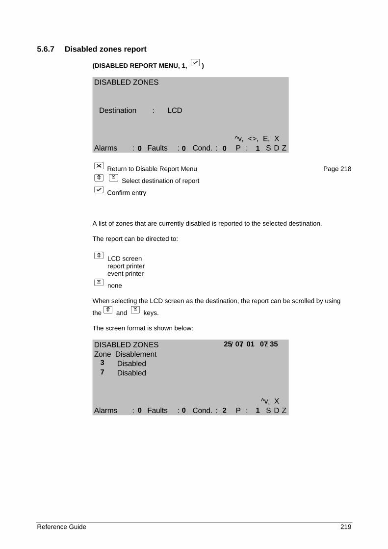
Reference Guide 219
5.6.7 Disabled zones report
(DISABLED REPORT MENU, 1, )
DISABLED ZONES
Destination : LCD
^v, <>, E, XAlarms : Faults : Cond. : P : S D Z
Return to Disable Report Menu Page 218
Select destination of report
Confirm entry
A list of zones that are currently disabled is reported to the selected destination.
The report can be directed to:
LCD screen report printer event printer
none
When selecting the LCD screen as the destination, the report can be scrolled by using
the and keys.
The screen format is shown below:
DISABLED ZONES / / :Zone Disablement
DisabledDisabled
^v, XAlarms : Faults : Cond. : P : S D Z
0 0 0 1
25 07 01 07 35
3 7
0 0 2 1
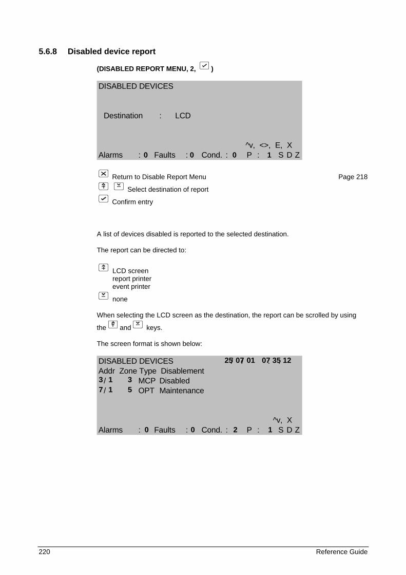
220 Reference Guide
5.6.8 Disabled device report
(DISABLED REPORT MENU, 2, )
DISABLED DEVICES
Destination : LCD
^v, <>, E, XAlarms : Faults : Cond. : P : S D Z
Return to Disable Report Menu Page 218
Select destination of report
Confirm entry
A list of devices disabled is reported to the selected destination.
The report can be directed to:
LCD screen report printer event printer
none
When selecting the LCD screen as the destination, the report can be scrolled by using
the and keys.
The screen format is shown below:
DISABLED DEVICES / / : :Addr Zone Type Disablement
/ MCP Disabled/ OPT Maintenance
^v, XAlarms : Faults : Cond. : P : S D Z
0 0 0 1
25 07 01 07 35 12 3 1 3 7 1 5 0 0 2 1
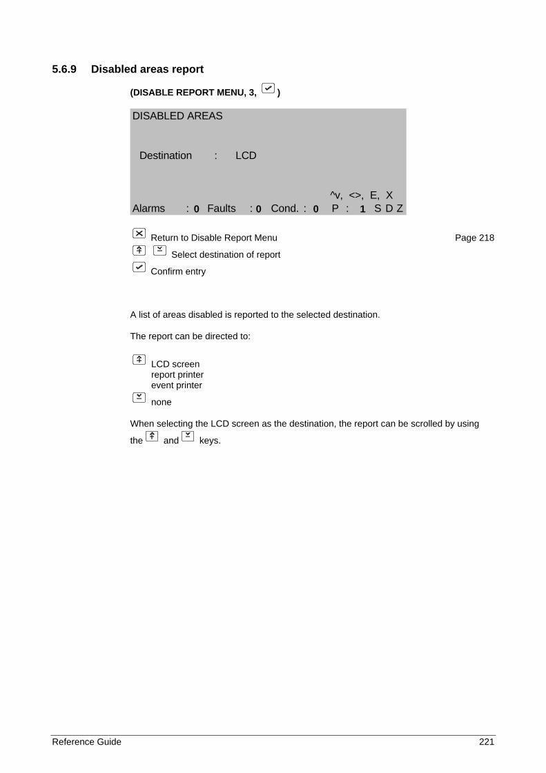
Reference Guide 221
5.6.9 Disabled areas report
(DISABLE REPORT MENU, 3, )
DISABLED AREAS
Destination : LCD
^v, <>, E, XAlarms : Faults : Cond. : P : S D Z
Return to Disable Report Menu Page 218
Select destination of report
Confirm entry
A list of areas disabled is reported to the selected destination.
The report can be directed to:
LCD screen report printer event printer
none
When selecting the LCD screen as the destination, the report can be scrolled by using
the and keys.
0 0 0 1
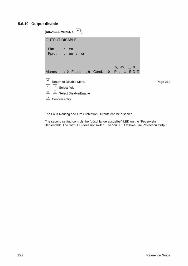
222 Reference Guide
5.6.10 Output disable
(DISABLE MENU, 5, )
OUTPUT DISABLE
Fltrt : enFprot : en / on
^v, <>, E, XAlarms : Faults : Cond. : P : S D Z
Return to Disable Menu Page 212
Select field
Select Disable/Enable
Confirm entry
The Fault Routing and Fire Protection Outputs can be disabled.
The second setting controls the “Löschlange ausgelöst” LED on the "Feuerwehr Bedienfeld". The “off” LED does not switch. The “on” LED follows Fire Protection Output.
0 0 0 1
Reference Guide 223
6 APPENDIX A
6.1 FP1200/2000 panel menus
The following table gives the field numbers (access field) of the FP1200/2000 Panel's menus. The table also shows what FP1200/2000 Panel configuration is required for a specific menu to exist.
6.2 Description
Field Number or Access Field:
This is a word value (two bytes) that is used to distinguish between the different menus. This is also the value that is used by FP1200/2000 Communication Format message number 16 to change or read the access level of a specific menu remotely.
The field numbers in the table is intended to show the menu hierarchy.
Existence Option:
The existence of the different menus for four FP2000 Panel configurations is shown. The configurations are:
• Absence of Field Loops
• Local Repeater
• Global Repeater
• Panel
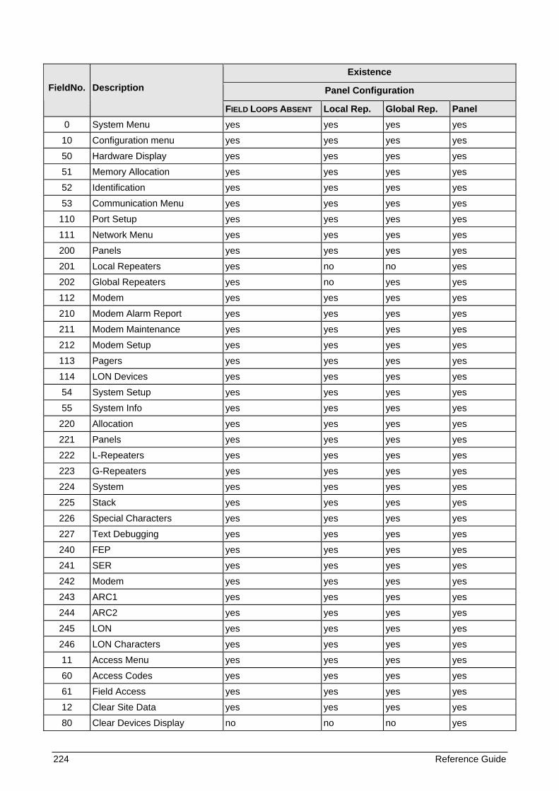
224 Reference Guide
Existence
Panel Configuration FieldNo. Description
FIELD LOOPS ABSENT Local Rep. Global Rep. Panel 0 System Menu yes yes yes yes
10 Configuration menu yes yes yes yes
50 Hardware Display yes yes yes yes
51 Memory Allocation yes yes yes yes
52 Identification yes yes yes yes
53 Communication Menu yes yes yes yes
110 Port Setup yes yes yes yes
111 Network Menu yes yes yes yes
200 Panels yes yes yes yes
201 Local Repeaters yes no no yes
202 Global Repeaters yes no yes yes
112 Modem yes yes yes yes
210 Modem Alarm Report yes yes yes yes
211 Modem Maintenance yes yes yes yes
212 Modem Setup yes yes yes yes
113 Pagers yes yes yes yes
114 LON Devices yes yes yes yes
54 System Setup yes yes yes yes
55 System Info yes yes yes yes
220 Allocation yes yes yes yes
221 Panels yes yes yes yes
222 L-Repeaters yes yes yes yes
223 G-Repeaters yes yes yes yes
224 System yes yes yes yes
225 Stack yes yes yes yes
226 Special Characters yes yes yes yes
227 Text Debugging yes yes yes yes
240 FEP yes yes yes yes
241 SER yes yes yes yes
242 Modem yes yes yes yes
243 ARC1 yes yes yes yes
244 ARC2 yes yes yes yes
245 LON yes yes yes yes
246 LON Characters yes yes yes yes
11 Access Menu yes yes yes yes
60 Access Codes yes yes yes yes
61 Field Access yes yes yes yes
12 Clear Site Data yes yes yes yes
80 Clear Devices Display no no no yes
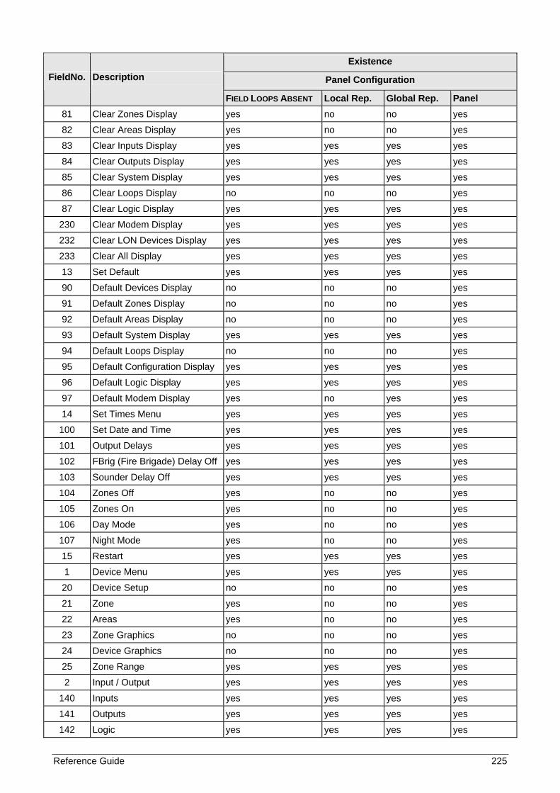
Reference Guide 225
Existence
Panel Configuration FieldNo. Description
FIELD LOOPS ABSENT Local Rep. Global Rep. Panel 81 Clear Zones Display yes no no yes
82 Clear Areas Display yes no no yes
83 Clear Inputs Display yes yes yes yes
84 Clear Outputs Display yes yes yes yes
85 Clear System Display yes yes yes yes
86 Clear Loops Display no no no yes
87 Clear Logic Display yes yes yes yes
230 Clear Modem Display yes yes yes yes
232 Clear LON Devices Display yes yes yes yes
233 Clear All Display yes yes yes yes
13 Set Default yes yes yes yes
90 Default Devices Display no no no yes
91 Default Zones Display no no no yes
92 Default Areas Display no no no yes
93 Default System Display yes yes yes yes
94 Default Loops Display no no no yes
95 Default Configuration Display yes yes yes yes
96 Default Logic Display yes yes yes yes
97 Default Modem Display yes no yes yes
14 Set Times Menu yes yes yes yes
100 Set Date and Time yes yes yes yes
101 Output Delays yes yes yes yes
102 FBrig (Fire Brigade) Delay Off yes yes yes yes
103 Sounder Delay Off yes yes yes yes
104 Zones Off yes no no yes
105 Zones On yes no no yes
106 Day Mode yes no no yes
107 Night Mode yes no no yes
15 Restart yes yes yes yes
1 Device Menu yes yes yes yes
20 Device Setup no no no yes
21 Zone yes no no yes
22 Areas yes no no yes
23 Zone Graphics no no no yes
24 Device Graphics no no no yes
25 Zone Range yes yes yes yes
2 Input / Output yes yes yes yes
140 Inputs yes yes yes yes
141 Outputs yes yes yes yes
142 Logic yes yes yes yes
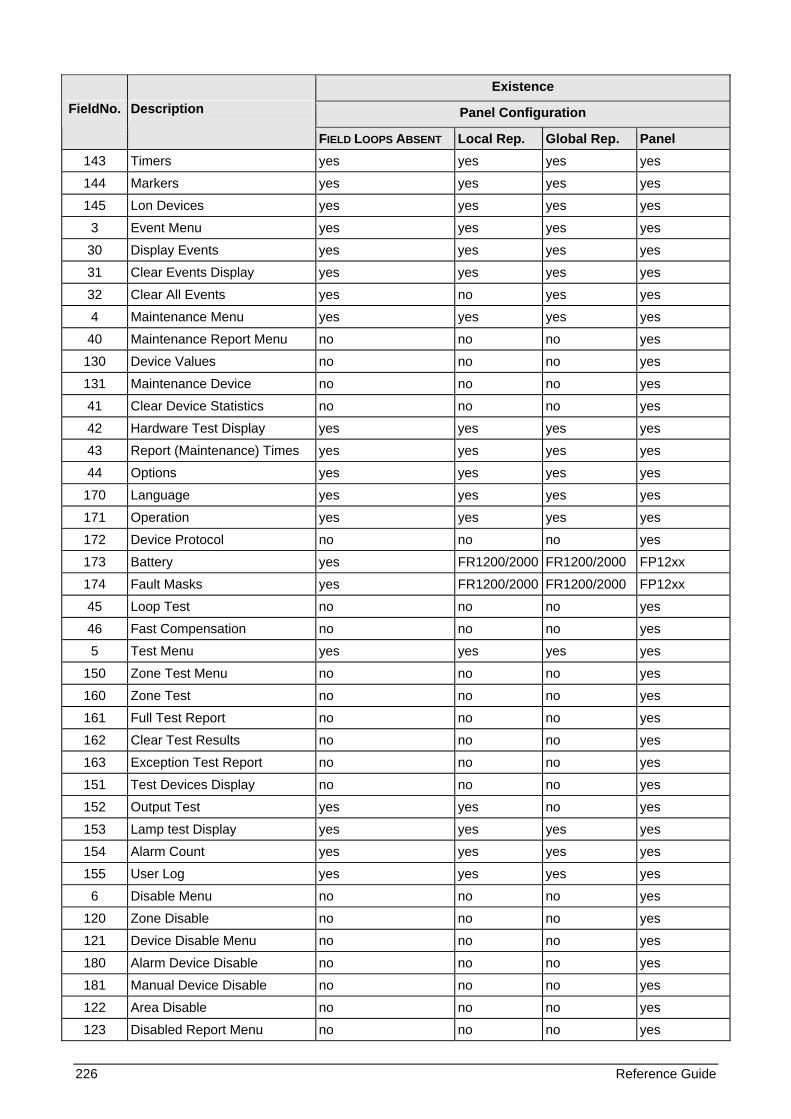
226 Reference Guide
Existence
Panel Configuration FieldNo. Description
FIELD LOOPS ABSENT Local Rep. Global Rep. Panel 143 Timers yes yes yes yes
144 Markers yes yes yes yes
145 Lon Devices yes yes yes yes
3 Event Menu yes yes yes yes
30 Display Events yes yes yes yes
31 Clear Events Display yes yes yes yes
32 Clear All Events yes no yes yes
4 Maintenance Menu yes yes yes yes
40 Maintenance Report Menu no no no yes
130 Device Values no no no yes
131 Maintenance Device no no no yes
41 Clear Device Statistics no no no yes
42 Hardware Test Display yes yes yes yes
43 Report (Maintenance) Times yes yes yes yes
44 Options yes yes yes yes
170 Language yes yes yes yes
171 Operation yes yes yes yes
172 Device Protocol no no no yes
173 Battery yes FR1200/2000 FR1200/2000 FP12xx
174 Fault Masks yes FR1200/2000 FR1200/2000 FP12xx
45 Loop Test no no no yes
46 Fast Compensation no no no yes
5 Test Menu yes yes yes yes
150 Zone Test Menu no no no yes
160 Zone Test no no no yes
161 Full Test Report no no no yes
162 Clear Test Results no no no yes
163 Exception Test Report no no no yes
151 Test Devices Display no no no yes
152 Output Test yes yes no yes
153 Lamp test Display yes yes yes yes
154 Alarm Count yes yes yes yes
155 User Log yes yes yes yes
6 Disable Menu no no no yes
120 Zone Disable no no no yes
121 Device Disable Menu no no no yes
180 Alarm Device Disable no no no yes
181 Manual Device Disable no no no yes
122 Area Disable no no no yes
123 Disabled Report Menu no no no yes

Reference Guide 227
Existence
Panel Configuration FieldNo. Description
FIELD LOOPS ABSENT Local Rep. Global Rep. Panel 190 Disabled Zones no no no yes
191 Disabled Devices no no no yes
192 Disabled Areas no no no yes
124 Output Disable yes yes yes yes

1052365
![FP1200 Spec Sheet (2) [Read-Only] - BuildSite.com · 2013. 8. 30. · Water absorption: ASTM 5-570](https://img.pdfslide.us/doc/110x75/613c93304c23507cb63578d0/fp1200-spec-sheet-2-read-only-2013-8-30-water-absorption-astm-5-570-.jpg)