Embed Size (px)
Citation preview
Responsible Committee Secretary: Mr Simon Merriman (BSI)Direct tel: 0208 996 7462E-mail: [email protected]
WARNING: THIS IS A DRAFT AND MUST NOT BE REGARDED OR USED AS A BRITISH STANDARD.THIS DRAFT IS NOT CURRENT BEYOND 11 August 2014
This draft is issued to allow comments from interested parties; all comments will be given consideration prior topublication. No acknowledgement will normally be sent. See overleaf for information on the submission ofcomments.
No copying is allowed, in any form, without prior written permission from BSI except as permitted under theCopyright, Designs and Patent Act 1988 or for circulation within a nominating organization for briefing purposes.Electronic circulation is limited to dissemination by e-mail within such an organization by committee members.
Further copies of this draft may be purchased from BSI Shop http://shop.bsigroup.comor from BSI Customer Services, Tel: +44(0) 20 8996 9001 or email [email protected], International and foreign standards are also available from BSI Customer Services.
Information on the co-operating organizations represented on the committees referenced above may be obtained fromhttp://standardsdevelopment.bsigroup.com
Latest date for receipt of comments: 11 August 2014 Project No. 2012/00171
Responsible committee: ISE/104 Concrete Reinforcing and Pre-Stressing Steels
Interested committees:
Date: 10 June 2014 Origin: International
DPC: 14 / 30258987 DC
Form 36Draft for Public Comment
BSI Group Headquarters
389 Chiswick High Road London W4 4AL
Tel: +44 (0)20 8996 9000Fax: +44 (0)20 8996 7400www.bsigroup.com
Title: Draft BS ISO 6935-2 Steel for the reinforcement of concrete
Part 2: Ribbed bars
Please notify the secretary if you are aware of any keywords that might assist in classifying or identifying thestandard or if the content of this standard
i) has any issues related to 3rd party IPR, patent or copyrightii) affects other national standard(s)iii) requires additional national guidance or information
IntroductionThis draft standard is based on international discussions in which the UK has taken an active part. Your commentson this draft are invited and will assist in the preparation of the consequent standard. Comments submitted will bereviewed by the relevant BSI committee before sending the consensus UK vote and comments to the internationalsecretariat, which will then decide appropriate action on the draft and the comments received.
If the international standard is approved, it is possible the text will be published as an identical British Standard.
UK VotePlease indicate whether you consider the UK should submit a negative (with reasons) or positive vote on this draft.
EXAMPLE ONLY
Microsoft and MS-DOS are registered trademarks, and Windows is a trademark of Microsoft Corporation.
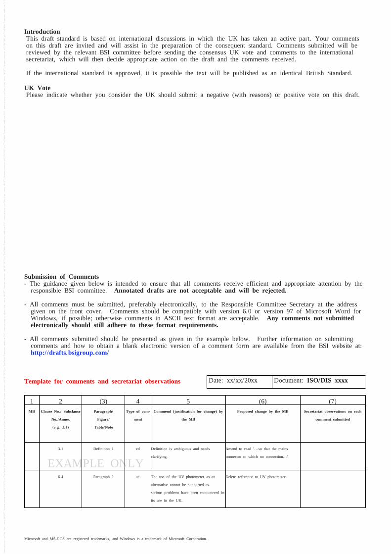
Submission of Comments- The guidance given below is intended to ensure that all comments receive efficient and appropriate attention by the
responsible BSI committee. Annotated drafts are not acceptable and will be rejected.
- All comments must be submitted, preferably electronically, to the Responsible Committee Secretary at the addressgiven on the front cover. Comments should be compatible with version 6.0 or version 97 of Microsoft Word forWindows, if possible; otherwise comments in ASCII text format are acceptable. Any comments not submittedelectronically should still adhere to these format requirements.
- All comments submitted should be presented as given in the example below. Further information on submittingcomments and how to obtain a blank electronic version of a comment form are available from the BSI website at:http://drafts.bsigroup.com/
Template for comments and secretariat observations Date: xx/xx/20xx Document: ISO/DIS xxxx
1 2 (3) 4 5 (6) (7)MB Clause No./ Subclause
No./Annex
(e.g. 3.1)
Paragraph/
Figure/
Table/Note
Type of com-
ment
Commend (justification for change) by
the MB
Proposed change by the MB Secretariat observations on each
comment submitted
3.1 Definition 1 ed Definition is ambiguous and needs
clarifying.
Amend to read '...so that the mains
connector to which no connection...'
6.4 Paragraph 2 te The use of the UV photometer as an
alternative cannot be supported as
serious problems have been encountered in
its use in the UK.
Delete reference to UV photometer.
© ISO 2014
Steel for the reinforcement of concrete —Part 2: Ribbed barsAciers pour l’armature du béton —Partie 2: Barres à verrous
Reference numberISO/DIS 6935-2:2014(E)
DRAFT INTERNATIONAL STANDARDISO/DIS 6935-2
THIS DOCUMENT IS A DRAFT CIRCULATED FOR COMMENT AND APPROVAL. IT IS THEREFORE SUBJECT TO CHANGE AND MAY NOT BE REFERRED TO AS AN INTERNATIONAL STANDARD UNTIL PUBLISHED AS SUCH.
IN ADDITION TO THEIR EVALUATION AS BEING ACCEPTABLE FOR INDUSTRIAL, TECHNOLOGICAL, COMMERCIAL AND USER PURPOSES, DRAFT INTERNATIONAL STANDARDS MAY ON OCCASION HAVE TO BE CONSIDERED IN THE LIGHT OF THEIR POTENTIAL TO BECOME STANDARDS TO WHICH REFERENCE MAY BE MADE IN NATIONAL REGULATIONS.
RECIPIENTS OF THIS DRAFT ARE INVITED TO SUBMIT, WITH THEIR COMMENTS, NOTIFICATION OF ANY RELEVANT PATENT RIGHTS OF WHICH THEY ARE AWARE AND TO PROVIDE SUPPORTING DOCUMENTATION.
ISO/TC 17/SC 16 Secretariat: SN
Voting begins on: Voting terminates on:2014-06-10 2014-09-10
ICS: 91.080.40;77.140.15
ISO/DIS 6935-2:2014(E)
ii © ISO 2014 – All rights reserved
Copyright notice
This ISO document is a Draft International Standard and is copyright-protected by ISO. Except as permitted under the applicable laws of the user’s country, neither this ISO draft nor any extract from it may be reproduced, stored in a retrieval system or transmitted in any form or by any means, electronic, photocopying, recording or otherwise, without prior written permission being secured.
Requests for permission to reproduce should be addressed to either ISO at the address below or ISO’s member body in the country of the requester.
ISO copyright officeCase postale 56 • CH-1211 Geneva 20Tel. + 41 22 749 01 11Fax + 41 22 749 09 47E-mail [email protected] www.iso.org
Reproduction may be subject to royalty payments or a licensing agreement.
Violators may be prosecuted.
ISO/DIS 6935-2
© ISO 2014 – All rights reserved iii
Contents Page
Foreword ............................................................................................................................................................ iv
1 Scope ...................................................................................................................................................... 1
2 Normative references ............................................................................................................................ 1
3 Symbols .................................................................................................................................................. 2
4 Terms and definitions ........................................................................................................................... 2
5 Dimensions, mass per unit length and permissible deviations ....................................................... 4
6 Requirements for ribs ........................................................................................................................... 5
7 Chemical composition .......................................................................................................................... 7
8 Mechanical properties ........................................................................................................................... 9 8.1 Tensile properties .................................................................................................................................. 9 8.2 Bending properties .............................................................................................................................. 11 8.3 Rebending properties after ageing .................................................................................................... 11 8.4 Fatigue properties ............................................................................................................................... 11
9 Testing .................................................................................................................................................. 11 9.1 Tensile test ........................................................................................................................................... 11 9.2 Bend test .............................................................................................................................................. 11 9.3 Rebend test .......................................................................................................................................... 12 9.4 Fatigue test .......................................................................................................................................... 12 9.5 Chemical composition ........................................................................................................................ 12
10 Designation .......................................................................................................................................... 12
11 Marking ................................................................................................................................................. 13 11.1 Marking on the bar .............................................................................................................................. 13 11.2 Marking of bundles .............................................................................................................................. 13
12 Evaluation of conformity .................................................................................................................... 13 12.1 General ................................................................................................................................................. 13 12.2 Certification scheme ........................................................................................................................... 13 12.3 Acceptance testing of a specific delivery ......................................................................................... 13 12.3.1 General ................................................................................................................................................. 13 12.3.2 Evaluation of characteristic values ................................................................................................... 14 12.3.3 Evaluation of specified minimum/maximum values ........................................................................ 15 12.3.4 Test report ............................................................................................................................................ 15
Annex A (informative) Four examples of marking systems for ribbed bars ............................................... 16 A.1 References ........................................................................................................................................... 16 A.2 Example No. 1: System according to EN 10080:2005 ...................................................................... 16 A.3 Example No. 2: System according to ASTM A615/A615M-13 and ASTM A706/A706M-13 ........... 17 A.4 Example No. 3: System according to JIS G 3112:2004 .................................................................... 18 A.5 Example No. 4: System according to GB 1499.2-2007 .................................................................... 19
Annex B (informative) Options for agreement between the manufacturer and purchaser ....................... 21
Bibliography ...................................................................................................................................................... 22
ISO/DIS 6935-2
iv © ISO 2014 – All rights reserved
Foreword
ISO (the International Organization for Standardization) is a worldwide federation of national standards bodies (ISO member bodies). The work of preparing International Standards is normally carried out through ISO technical committees. Each member body interested in a subject for which a technical committee has been established has the right to be represented on that committee. International organizations, governmental and non-governmental, in liaison with ISO, also take part in the work. ISO collaborates closely with the International Electrotechnical Commission (IEC) on all matters of electrotechnical standardization.
International Standards are drafted in accordance with the rules given in the ISO/IEC Directives, Part 2.
The main task of technical committees is to prepare International Standards. Draft International Standards adopted by the technical committees are circulated to the member bodies for voting. Publication as an International Standard requires approval by at least 75 % of the member bodies casting a vote.
Attention is drawn to the possibility that some of the elements of this document may be the subject of patent rights. ISO shall not be held responsible for identifying any or all such patent rights.
ISO 6935-2 was prepared by Technical Committee ISO/TC 17, Steel, Subcommittee SC 16, Steels for the reinforcement and prestressing of concrete.
This third edition cancels and replaces the second edition (ISO 6935-2:2007), which has been technically revised.
ISO 6935 consists of the following parts, under the general title Steel for the reinforcement of concrete:
Part 1: Plain bars
Part 2: Ribbed bars
Part 3: Welded fabric
DRAFT INTERNATIONAL STANDARD ISO/DIS 6935-2
© ISO 2014 – All rights reserved 1
Steel for the reinforcement of concrete — Part 2: Ribbed bars
1 Scope
This part of ISO 6935 specifies technical requirements for ribbed bars to be used as reinforcement in concrete.
The standard covers steel delivered in the form of bars, coils and de-coiled products. This part of ISO 6935 covers thirteen steel grades not intended for welding which are B300A-R, B300B-R, B300C R, B300D-R, B400A-R, B400B-R, B400C-R, B500A-R, B500B-R, B500C-R, B600 A-R, B600B-R and B600C-R, and eleven steel grades intended for welding which are B300DWR, B350DWR, B400AWR, B400BWR, B400CWR, B400DWR, B420DWR, B500AWR, B500BWR, B500CWR and B500DWR. The steel grades are designated with steel names allocated in accordance with ISO/TS 4949.
NOTE The first “B” stands for steel for reinforcing concrete. The next 3 digits represent the specified characteristic value of minimum upper yield strength. The fifth symbol stands for ductility class (4.5). The sixth symbol relates to welding; “-” means not intended for welding and “W” means intended for welding. The last “R” stands for ribbed bar.
This part of ISO 6935 covers products delivered in cut lengths or coils.
The production process is at the discretion of the manufacturer.
Ribbed bars produced from finished products, such as plates and railway rails, are excluded.
2 Normative references
The following referenced documents are indispensable for the application of this document. For dated references, only the edition cited applies. For undated references, the latest edition of the referenced document (including any amendments) applies.
ISO 404, Steel and steel products — General technical delivery requirements
ISO/TS 4949, Steel names based on letter symbols
ISO/TR 9769, Steel and iron — Review of available methods of analysis
ISO 10144, Certification scheme for steel bars and wires for the reinforcement of concrete structures
ISO 14284, Steel and iron — Sampling and preparation of samples for the determination of chemical composition
ISO 15630-1, Steel for the reinforcement and prestressing of concrete — Test methods — Part 1: Reinforcing bars, wire rod and wire
ISO/DIS 6935-2
2 © ISO 2014 – All rights reserved
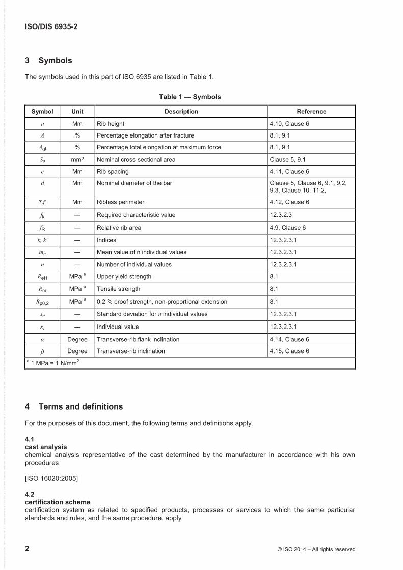
3 Symbols
The symbols used in this part of ISO 6935 are listed in Table 1.
Table 1 — Symbols
Symbol Unit Description Reference
a Mm Rib height 4.10, Clause 6
A % Percentage elongation after fracture 8.1, 9.1
Agt % Percentage total elongation at maximum force 8.1, 9.1
S0 mm2 Nominal cross-sectional area Clause 5, 9.1
c Mm Rib spacing 4.11, Clause 6
d Mm Nominal diameter of the bar Clause 5, Clause 6, 9.1, 9.2, 9.3, Clause 10, 11.2,
fi Mm Ribless perimeter 4.12, Clause 6
fk — Required characteristic value 12.3.2.3
fR — Relative rib area 4.9, Clause 6
k, k' — Indices 12.3.2.3.1
mn — Mean value of n individual values 12.3.2.3.1
n — Number of individual values 12.3.2.3.1
ReH MPa a Upper yield strength 8.1
Rm MPa a Tensile strength 8.1
Rp0,2 MPa a 0,2 % proof strength, non-proportional extension 8.1
sn — Standard deviation for n individual values 12.3.2.3.1
xi — Individual value 12.3.2.3.1
α Degree Transverse-rib flank inclination 4.14, Clause 6
Degree Transverse-rib inclination 4.15, Clause 6 a 1 MPa = 1 N/mm2
4 Terms and definitions
For the purposes of this document, the following terms and definitions apply.
4.1 cast analysis chemical analysis representative of the cast determined by the manufacturer in accordance with his own procedures
[ISO 16020:2005]
4.2 certification scheme certification system as related to specified products, processes or services to which the same particular standards and rules, and the same procedure, apply
ISO/DIS 6935-2
© ISO 2014 – All rights reserved 3
4.3 characteristic value value having a prescribed probability of not being attained in a hypothetical unlimited test series
[ISO 16020:2005]
NOTE 1 Equivalent to “fractile”, which is defined in ISO 3534-1.
NOTE 2 A nominal value is used as the characteristic value in some circumstances.
4.4 core part of the cross-section of the bar containing neither ribs nor indentations
NOTE Adapted from ISO 16020:2005.
4.5 ductility class classification of the ductility properties of reinforcing steels based on the value of the ratio of tensile strength to yield strength, as well as the elongation measured either as Agt or as A
NOTE See Table 6.
4.6 longitudinal rib uniform continuous rib parallel to the axis of the bar
NOTE Adapted from ISO 16020:2005.
4.7 nominal cross-sectional area cross-sectional area equivalent to the area of a circular plain bar of the nominal diameter
NOTE Adapted from ISO 16020:2005.
4.8 product analysis chemical analysis carried out on the product
[ISO 16020:2005]
4.9 relative rib area fR area of the projections of all transverse ribs within a defined length on a plane perpendicular to the longitudinal axis of the bar, divided by this length and the nominal circumference
NOTE Adapted from ISO 16020:2005.
4.10 rib height a distance from the highest point on the rib to the surface of the core, to be measured perpendicular to the axis of the bar
NOTE 1 See Figure 2.
NOTE 2 Adapted from ISO 16020:2005.
ISO/DIS 6935-2
4 © ISO 2014 – All rights reserved
4.11 rib spacing c distance between the centres of two consecutive transverse ribs measured parallel to the axis of the bar
NOTE 1 See Figure 1.
NOTE 2 Adapted from ISO 16020:2005.
4.12 ribless perimeter fi sum of the distances along the surface of the core between the end of the transverse ribs of adjacent rows measured as the projection on a plane perpendicular to the axis of the bar
NOTE Adapted from ISO 16020:2005.
4.13 transverse rib rib at an angle, either perpendicular or oblique, to the longitudinal axis of the bar
NOTE Adapted from ISO 16020:2005.
4.14 transverse-rib flank inclination angle between the flank of a transverse rib and the core surface of a bar measured perpendicular to the longitudinal axis of the transverse rib
NOTE 1 See Figure 2.
NOTE 2 Adapted from ISO 16020:2005.
4.15 transverse-rib inclination angle between the rib and the longitudinal axis of the bar
NOTE 1 See Figures 1, 3 and 4.
NOTE 2 Adapted from ISO 16020:2005.
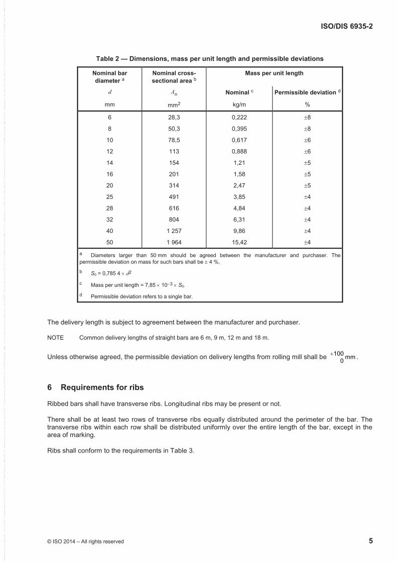
5 Dimensions, mass per unit length and permissible deviations
Dimensions, mass per unit length and permissible deviations are given in Table 2. By agreement between the manufacturer and purchaser, ribbed bars whose nominal diameters are other than those shown in Table 2 may be used.
ISO/DIS 6935-2
© ISO 2014 – All rights reserved 5
Table 2 — Dimensions, mass per unit length and permissible deviations
Nominal bar diameter a
Nominal cross-sectional area b
Mass per unit length
d An Nominal c Permissible deviation d
mm mm2 kg/m %
6
8
10
12
14
16
20
25
28
32
40
50
28,3
50,3
78,5
113
154
201
314
491
616
804
1 257
1 964
0,222
0,395
0,617
0,888
1,21
1,58
2,47
3,85
4,84
6,31
9,86
15,42
8
8
6
6
5
5
5
4
4
4
4
4
a Diameters larger than 50 mm should be agreed between the manufacturer and purchaser. The permissible deviation on mass for such bars shall be 4 %.
b S0 = 0,785 4 d2
c Mass per unit length = 7,85 103 S0.
d Permissible deviation refers to a single bar.
The delivery length is subject to agreement between the manufacturer and purchaser.
NOTE Common delivery lengths of straight bars are 6 m, 9 m, 12 m and 18 m.
Unless otherwise agreed, the permissible deviation on delivery lengths from rolling mill shall be 100 mm0 .
6 Requirements for ribs
Ribbed bars shall have transverse ribs. Longitudinal ribs may be present or not.
There shall be at least two rows of transverse ribs equally distributed around the perimeter of the bar. The transverse ribs within each row shall be distributed uniformly over the entire length of the bar, except in the area of marking.
Ribs shall conform to the requirements in Table 3.
ISO/DIS 6935-2
6 © ISO 2014 – All rights reserved
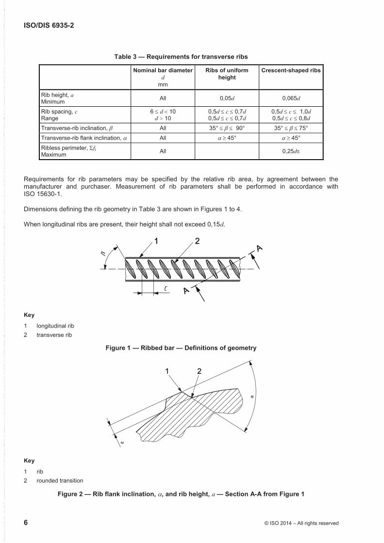
Table 3 — Requirements for transverse ribs
Nominal bar diameter d
mm
Ribs of uniform height
Crescent-shaped ribs
Rib height, a Minimum All 0,05d 0,065d
Rib spacing, c Range
6 d 10 d > 10
0,5d c 0,7d 0,5d c 0,7d
0,5d c 1,0d
0,5d c 0,8d
Transverse-rib inclination, All 35° 90° 35° 75°
Transverse-rib flank inclination, All 45° 45°
Ribless perimeter, fi Maximum All 0,25d
Requirements for rib parameters may be specified by the relative rib area, by agreement between the manufacturer and purchaser. Measurement of rib parameters shall be performed in accordance with ISO 15630-1.
Dimensions defining the rib geometry in Table 3 are shown in Figures 1 to 4.
When longitudinal ribs are present, their height shall not exceed 0,15d.
Key
1 longitudinal rib 2 transverse rib
Figure 1 — Ribbed bar — Definitions of geometry
Key
1 rib 2 rounded transition
Figure 2 — Rib flank inclination, , and rib height, a — Section A-A from Figure 1
ISO/DIS 6935-2
© ISO 2014 – All rights reserved 7
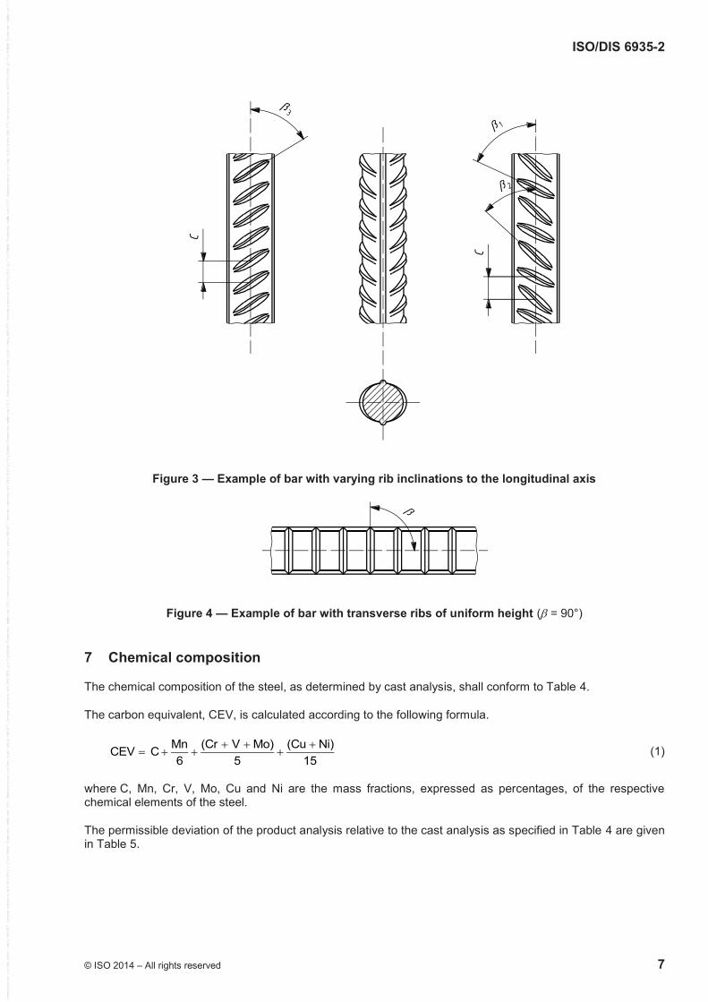
Figure 3 — Example of bar with varying rib inclinations to the longitudinal axis
Figure 4 — Example of bar with transverse ribs of uniform height ( = 90°)
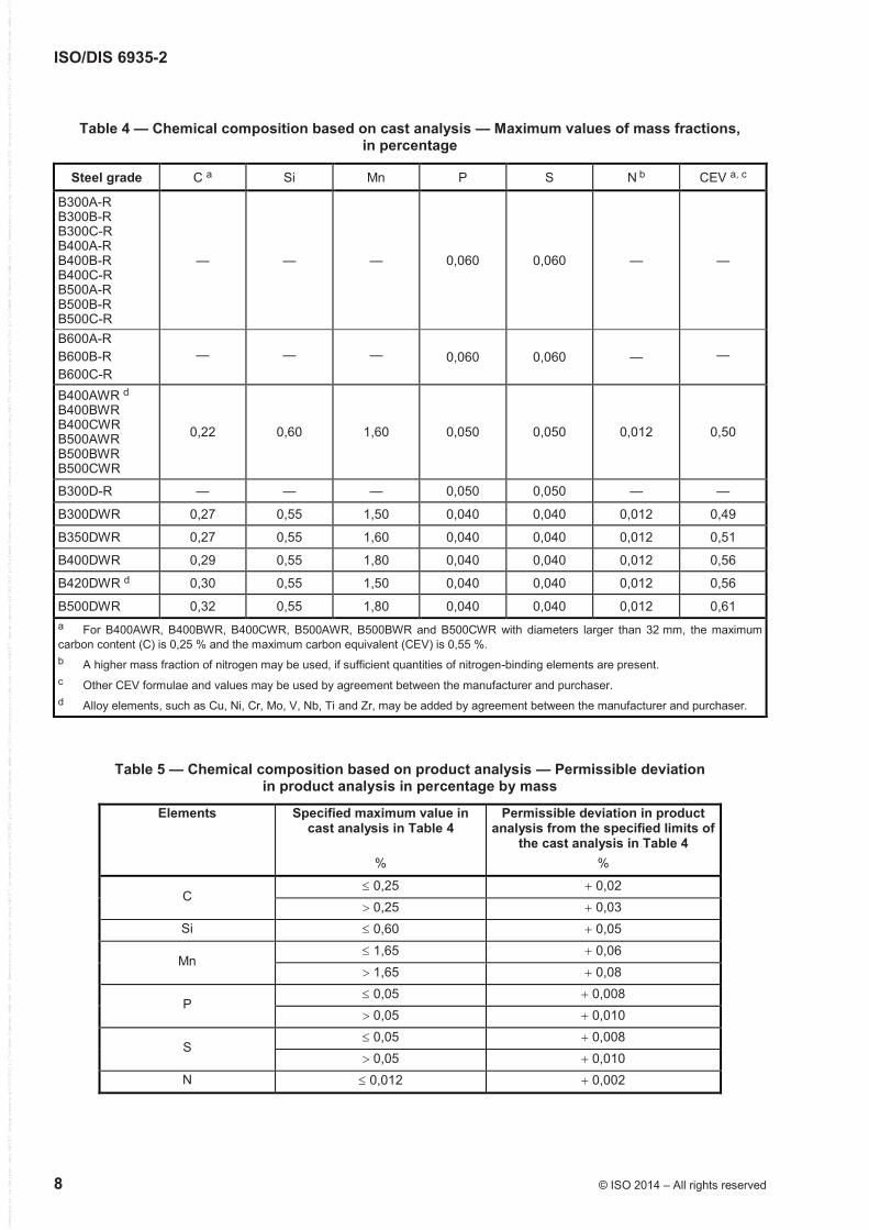
7 Chemical composition
The chemical composition of the steel, as determined by cast analysis, shall conform to Table 4.
The carbon equivalent, CEV, is calculated according to the following formula.
Mn (Cr V Mo) (Cu Ni)CEV C6 5 15
(1)
where C, Mn, Cr, V, Mo, Cu and Ni are the mass fractions, expressed as percentages, of the respective chemical elements of the steel.
The permissible deviation of the product analysis relative to the cast analysis as specified in Table 4 are given in Table 5.
ISO/DIS 6935-2
8 © ISO 2014 – All rights reserved
Table 4 — Chemical composition based on cast analysis — Maximum values of mass fractions, in percentage
Steel grade C a Si Mn P S N b CEV a, c
B300A-R B300B-R B300C-R B400A-R B400B-R B400C-R B500A-R B500B-R B500C-R
— — — 0,060 0,060 — —
B600A-R B600B-R B600C-R
— — — 0,060 0,060 — —
B400AWR d B400BWR B400CWR B500AWR B500BWR B500CWR
0,22 0,60 1,60 0,050 0,050 0,012 0,50
B300D-R — — — 0,050 0,050 — —
B300DWR 0,27 0,55 1,50 0,040 0,040 0,012 0,49
B350DWR 0,27 0,55 1,60 0,040 0,040 0,012 0,51
B400DWR 0,29 0,55 1,80 0,040 0,040 0,012 0,56
B420DWR d 0,30 0,55 1,50 0,040 0,040 0,012 0,56
B500DWR 0,32 0,55 1,80 0,040 0,040 0,012 0,61 a For B400AWR, B400BWR, B400CWR, B500AWR, B500BWR and B500CWR with diameters larger than 32 mm, the maximum carbon content (C) is 0,25 % and the maximum carbon equivalent (CEV) is 0,55 %. b A higher mass fraction of nitrogen may be used, if sufficient quantities of nitrogen-binding elements are present. c Other CEV formulae and values may be used by agreement between the manufacturer and purchaser. d Alloy elements, such as Cu, Ni, Cr, Mo, V, Nb, Ti and Zr, may be added by agreement between the manufacturer and purchaser.
Table 5 — Chemical composition based on product analysis — Permissible deviation in product analysis in percentage by mass
Elements Specified maximum value in cast analysis in Table 4
%
Permissible deviation in product analysis from the specified limits of
the cast analysis in Table 4 %
C 0,25 0,02 0,25 0,03
Si 0,60 0,05
Mn 1,65 0,06 1,65 0,08
P 0,05 0,008 0,05 0,010
S 0,05 0,008 0,05 0,010
N 0,012 0,002
ISO/DIS 6935-2
© ISO 2014 – All rights reserved 9
8 Mechanical properties
8.1 Tensile properties
The tensile test shall be performed in accordance with 9.1.
The material shall conform to the requirements for tensile properties specified in Table 6.
In the context of this part of ISO 6935, the characteristic value is (unless otherwise indicated) the lower or upper limit of the statistical tolerance interval at which there is a 90 % probability (1 = 0,90) that 95 % (p = 0,95) of the values are at or above this lower limit, or are at or below this upper limit, respectively. This definition refers to the long-term quality level of production.
ISO/DIS 6935-2
10 © ISO 2014 – All rights reserved
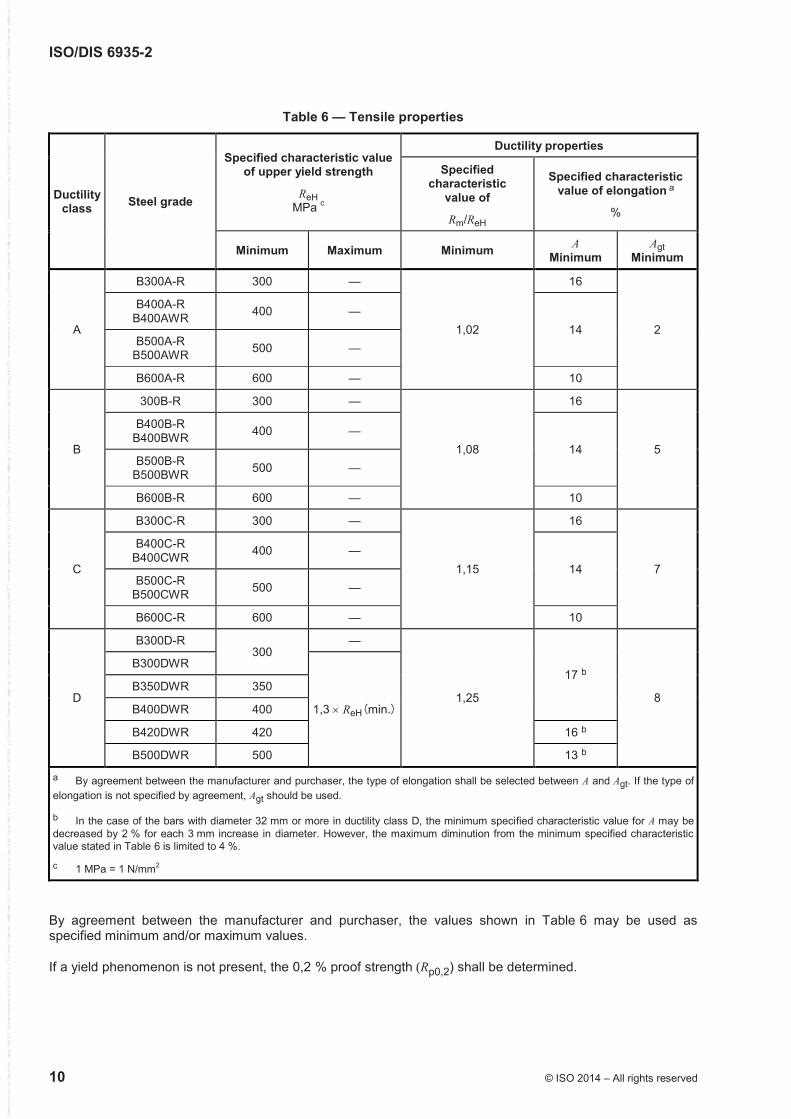
Table 6 — Tensile properties
Ductility class Steel grade
Specified characteristic value of upper yield strength
ReH MPa c
Ductility properties
Specified characteristic
value of
Rm/ReH
Specified characteristic value of elongation a
%
Minimum Maximum Minimum A Minimum
Agt Minimum
A
B300A-R 300 —
1,02
16
2
B400A-R B400AWR 400 —
14 B500A-R
B500AWR 500 —
B600A-R 600 — 10
B
300B-R 300 —
1,08
16
5
B400B-R B400BWR 400 —
14 B500B-R
B500BWR 500 —
B600B-R 600 — 10
C
B300C-R 300 —
1,15
16
7
B400C-R B400CWR 400 —
14 B500C-R
B500CWR 500 —
B600C-R 600 — 10
D
B300D-R 300
—
1,25
17 b
8
B300DWR
1,3 ReH(min.)
B350DWR 350
B400DWR 400
B420DWR 420 16 b
B500DWR 500 13 b
a By agreement between the manufacturer and purchaser, the type of elongation shall be selected between A and Agt. If the type of elongation is not specified by agreement, Agt should be used.
b In the case of the bars with diameter 32 mm or more in ductility class D, the minimum specified characteristic value for A may be decreased by 2 % for each 3 mm increase in diameter. However, the maximum diminution from the minimum specified characteristic value stated in Table 6 is limited to 4 %.
c 1 MPa = 1 N/mm2
By agreement between the manufacturer and purchaser, the values shown in Table 6 may be used as specified minimum and/or maximum values.
If a yield phenomenon is not present, the 0,2 % proof strength (Rp0,2) shall be determined.
ISO/DIS 6935-2
© ISO 2014 – All rights reserved 11
8.2 Bending properties
The bend test shall be performed in accordance with 9.2. After testing, the bars shall show neither rupture nor cracks visible to a person of normal or corrected vision.
8.3 Rebending properties after ageing
Regarding fifteen steel grades of B400A-R, B400B-R, B400C-R, B400AWR, B400BWR, B400CWR, B400DWR, B420DWR, B500A-R, B500B-R, B500C-R, B500AWR, B500BWR, B500CWR and B500DWR, if required by the purchaser, the rebend test shall be performed in accordance with 9.3.
NOTE The rebend test is used to verify the ageing properties of the bent bars.
After testing, the bars shall show neither rupture nor cracks visible to a person of normal or corrected vision.
8.4 Fatigue properties
If required by the purchaser, the manufacturer shall demonstrate the fatigue properties of the product based on axial-force-controlled fatigue testing in the fluctuating tension range in accordance with 9.4.
The specified number(s) of stress cycles, stress range(s) 2a and maximum stress(es) max shall be as agreed between the purchaser and manufacturer at the time of enquiry and order.
9 Testing
9.1 Tensile test
The tensile test shall be carried out in accordance with ISO 15630-1.
For the determination of percentage elongation after fracture, A, the original gauge length shall be 5 times the nominal diameter.
For the determination of percentage total elongation at maximum force, Agt, equidistant marks shall be made on the free length of the test piece. The distance between the marks shall be 20 mm, 10 mm or 5 mm, depending on the bar diameter.
For determination of tensile properties, the nominal cross-sectional area of the bar shall be used.
9.2 Bend test
The bend test shall be carried out in accordance with ISO 15630-1.
The test piece shall be bent to an angle between 160° and 180° over a mandrel of the diameter specified in Table 7.
ISO/DIS 6935-2
12 © ISO 2014 – All rights reserved
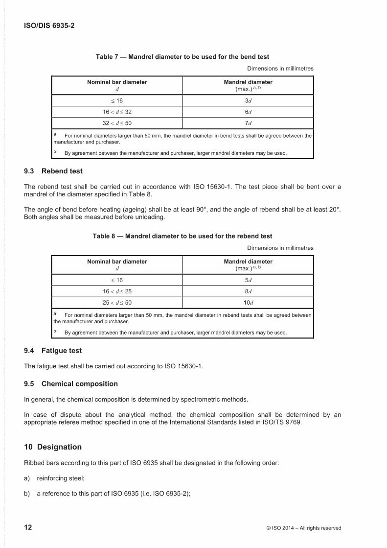
Table 7 — Mandrel diameter to be used for the bend test
Dimensions in millimetres
Nominal bar diameter d
Mandrel diameter (max.) a, b
16 3d
16 d 32 6d
32 d 50 7d
a For nominal diameters larger than 50 mm, the mandrel diameter in bend tests shall be agreed between the manufacturer and purchaser.
b By agreement between the manufacturer and purchaser, larger mandrel diameters may be used.
9.3 Rebend test
The rebend test shall be carried out in accordance with ISO 15630-1. The test piece shall be bent over a mandrel of the diameter specified in Table 8.
The angle of bend before heating (ageing) shall be at least 90°, and the angle of rebend shall be at least 20°. Both angles shall be measured before unloading.
Table 8 — Mandrel diameter to be used for the rebend test
Dimensions in millimetres
Nominal bar diameter d
Mandrel diameter (max.) a, b
16 5d
16 d 25 8d
25 d 50 10d
a For nominal diameters larger than 50 mm, the mandrel diameter in rebend tests shall be agreed between the manufacturer and purchaser.
b By agreement between the manufacturer and purchaser, larger mandrel diameters may be used.
9.4 Fatigue test
The fatigue test shall be carried out according to ISO 15630-1.
9.5 Chemical composition
In general, the chemical composition is determined by spectrometric methods.
In case of dispute about the analytical method, the chemical composition shall be determined by an appropriate referee method specified in one of the International Standards listed in ISO/TS 9769.
10 Designation
Ribbed bars according to this part of ISO 6935 shall be designated in the following order:
a) reinforcing steel;
b) a reference to this part of ISO 6935 (i.e. ISO 6935-2);
ISO/DIS 6935-2
© ISO 2014 – All rights reserved 13
c) the nominal diameter, in millimetres, according to Table 2;
d) the steel grade.
EXAMPLE Reinforcing steel ISO 6935-2 – 12 B500CWR
11 Marking
11.1 Marking on the bar
All bars should be identifiable by marks introduced during rolling which indicate
a) the steel grade,
b) the name of the manufacturer.
Some examples of multinational marking systems are shown in Annex A.
11.2 Marking of bundles
Each bundle of bars shall have a label stating the name of the manufacturer, a reference to this part of ISO 6935 (i.e. ISO 6935-2), the steel grade, the nominal diameter, the cast number or reference related to the test record and country of origin.
12 Evaluation of conformity
12.1 General
Certification and inspection of reinforcement shall be performed
a) in accordance with a certification scheme monitored by an external body, or
b) according to testing of a specific delivery.
12.2 Certification scheme
In the case of a certification scheme, evaluation of conformity shall be performed in accordance with ISO 10144.
12.3 Acceptance testing of a specific delivery
12.3.1 General
Provisions regarding the nature, extent and evaluation of acceptance testing on deliveries of reinforcing steel not subject to a certification scheme are given in 12.3.2 and 12.3.3.
Acceptance testing of a specific delivery shall be performed according to 12.3.2.
By agreement between the manufacturer and purchaser, 12.3.3 may be used.
ISO/DIS 6935-2
14 © ISO 2014 – All rights reserved
12.3.2 Evaluation of characteristic values
12.3.2.1 Organization
The tests shall be organized and carried out according to an agreement between the purchaser and manufacturer, taking into consideration the national rules of the receiving country.
12.3.2.2 Extent of sampling and testing
For the purpose of testing, the delivery shall be subdivided into test units with a maximum mass of 50 t, or a fraction thereof. Each test unit shall consist of products of the same steel grade and the same nominal diameter from the same cast. The manufacturer shall confirm in the test report that all samples in the test unit originate from the same cast. The chemical composition (cast analysis) shall be stated in this test report.
Test pieces shall be taken from each test unit as follows:
a) two test pieces from various bars for testing the chemical composition (product analysis);
b) a minimum of 15 test pieces (if appropriate, 60 test pieces, see 12.3.2.3.1) from various bars for testing all other properties specified in this part of ISO 6935.
12.3.2.3 Evaluation of the results
12.3.2.3.1 Inspection by variables
For properties which are specified as characteristic values, the following shall be determined:
a) all individual values, xi, of the 15 test pieces (n = 15);
b) the mean value, m15 (for n = 15);
c) the standard deviation, s15 (for n = 15).
The test unit corresponds to the requirements, if the condition stated below is fulfilled for all properties:
15 15 k2,33m s f W (2)
where
fk is the required characteristic value;
2,33 is the value for the acceptability index, k, for n = 15 for a failure rate of 5 % (p = 0,95) at a probability of 90 % (1 – = 0,90).
2
1515 14
ix ms
(3)
If the condition stated above is not fulfilled, the index
15 k
15
m fk
s
(4)
is determined from the test results available. Where k W 2, testing can be continued. In this case, 45 further test pieces shall be taken and tested from different bars in the test unit, so that a total of 60 test results are available (n = 60).
ISO/DIS 6935-2
© ISO 2014 – All rights reserved 15
The test unit shall be considered to comply with the requirements, if the condition stated below is fulfilled for all properties:
60 60 k1,93m s f (5)
where 1,93 is the value for the acceptability index, k, for n = 60 for a failure rate of 5 % (p = 0,95) at a probability of 90 % (1 – = 0,90).
12.3.2.3.2 Inspection by attributes
When testing properties are specified as maximum or minimum values, all results determined on the 15 test pieces shall comply with the requirements of this part of ISO 6935. In this case, the test unit shall be considered to comply with the requirements.
The tests may be continued when at most 2 results not conforming to the conditions occur. In this case, 45 additional test pieces from various bars in the test unit shall be tested, so that a total of 60 test results are available. The test unit complies with the requirements if not more than 2 of the 60 results do not conform to the conditions.
12.3.2.3.3 Chemical composition
Both test pieces shall comply with the requirements in this part of ISO 6935.
12.3.3 Evaluation of specified minimum/maximum values
Tests shall be carried out according to the following:
a) Bars of the same cast shall constitute one group. For every 50 t or fraction thereof, one tensile test and one bend/rebend test shall be carried out for each bar diameter;
b) Each individual test result shall meet the required values in Table 6, and the required bending/rebending properties in 8.2 and 8.3. One cast analysis shall be carried out for every cast to verify chemical composition (Clause 7). Samples shall be taken in accordance with ISO 14284;
c) If any test result does not meet the requirements, retests may be carried out, according to ISO 404;
d) The manufacturer shall submit a test report stating that the products of the delivery satisfy the chemical and mechanical properties defined in Clauses 7 and 8, and a confirmation that the other requirements of this part of ISO 6935 are fulfilled.
12.3.4 Test report
The test report shall contain the following information:
a) designation of the reinforcing steel in accordance with this part of ISO 6935;
b) marking on the reinforcing steel;
c) date of testing;
d) mass of the test unit;
e) test results.
ISO/DIS 6935-2
16 © ISO 2014 – All rights reserved
Annex A (informative)
Four examples of marking systems for ribbed bars
A.1 References
EN 10080:2005, Steel for the reinforcement of concrete — Weldable reinforcing steel — General
ASTM A615/A615M-13. Standard specification for deformed and plain carbon-steel bars for concrete reinforcement
ASTM A706/A706M-13. Standard specification for low-alloy steel deformed and plain bars for concrete reinforcement
JIS G 3112:2004, Steel bars for concrete reinforcement
GB 1499.2-2007, Hot rolled ribbed steel bars for the reinforcement of concrete
A.2 Example No. 1: System according to EN 10080:2005
A.2.1 Each reinforcing bar shall bear on one rib row a mark identifying the works. This mark shall be repeated at an interval of not more than 1,5 m.
A.2.2 The mark shall consist of the following:
a) a symbol denoting the beginning of the mark;
b) a numerical system identifying the manufacturer, consisting of a country-of-origin number and a works number.
A.2.3 The numerical system identifying the country of origin and the works shall use one of the following methods.
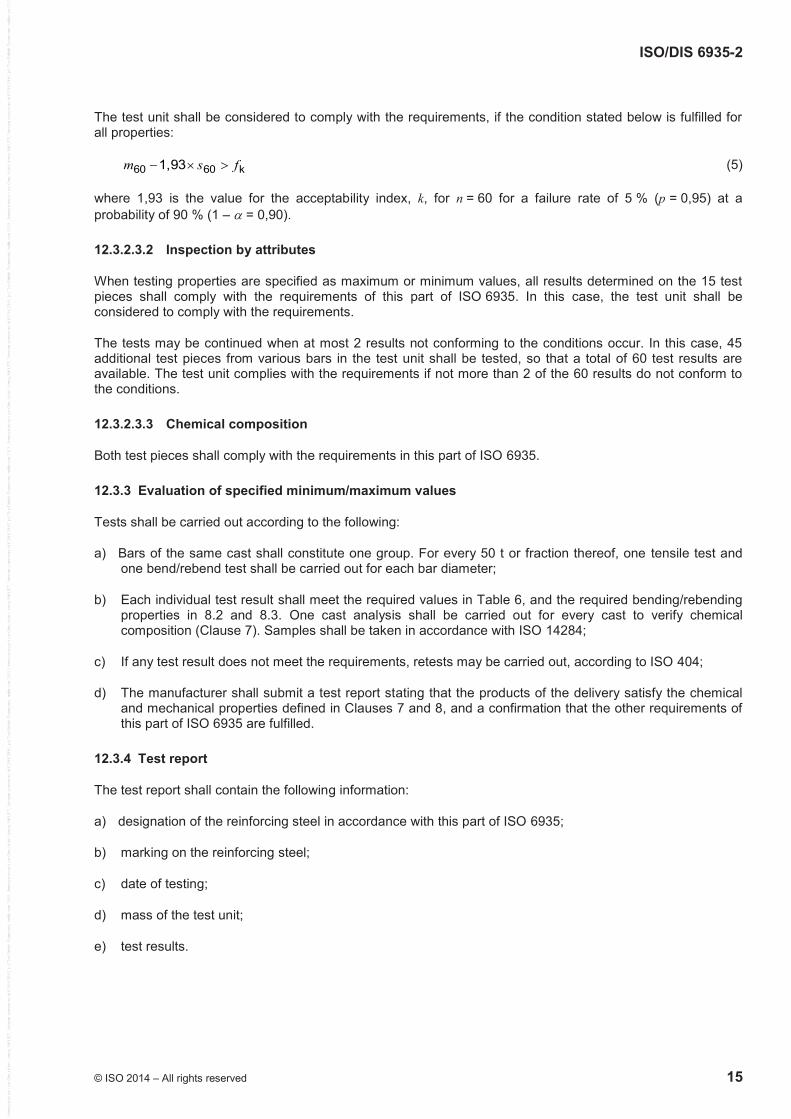
a) A number of normal ribs or indentations between widened ribs or indentations (for example, see Figure A.1).
b) A number of normal ribs or indentations between missing ribs or indentations.
c) Numbers on the surface of the bar.
d) Rolled or indented marks with a number of normal ribs or indentations in between them.
Start Country No 4 Works No 16
Figure A.1 — Example of manufacturer's identification mark (using widened ribs)
ISO/DIS 6935-2
© ISO 2014 – All rights reserved 17
A.2.4 The symbol indicating the start of the mark shall be one of the following:
a) where the marking method uses widened ribs or indentations, the symbol identifying the start of the mark shall consist of two consecutive widened ribs or indentations. (For example, see Figure A.1.);
b) where the marking method uses missing ribs or indentations, the symbol identifying the start of the mark shall consist of two consecutive missing ribs or indentations;
c) where numbers are rolled onto the surface of the bar, the symbol indicating the start of the mark shall be an X or O;
d) where marks are rolled or indented onto the surface, the start of the mark shall consist of two marks between one pair of normal ribs or indentations.
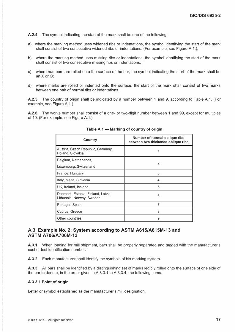
A.2.5 The country of origin shall be indicated by a number between 1 and 9, according to Table A.1. (For example, see Figure A.1.)
A.2.6 The works number shall consist of a one- or two-digit number between 1 and 99, except for multiples of 10. (For example, see Figure A.1.)
Table A.1 — Marking of country of origin
Country Number of normal oblique ribs between two thickened oblique ribs
Austria, Czech Republic, Germany, Poland, Slovakia 1
Belgium, Netherlands,
Luxemburg, Switzerland 2
France, Hungary 3
Italy, Malta, Slovenia 4
UK, Ireland, Iceland 5
Denmark, Estonia, Finland, Latvia, Lithuania, Norway, Sweden 6
Portugal, Spain 7
Cyprus, Greece 8
Other countries 9
A.3 Example No. 2: System according to ASTM A615/A615M-13 and ASTM A706/A706M-13
A.3.1 When loading for mill shipment, bars shall be properly separated and tagged with the manufacturer’s cast or test identification number.
A.3.2 Each manufacturer shall identify the symbols of his marking system.
A.3.3 All bars shall be identified by a distinguishing set of marks legibly rolled onto the surface of one side of the bar to denote, in the order given in A.3.3.1 to A.3.3.4, the following items.
A.3.3.1 Point of origin
Letter or symbol established as the manufacturer's mill designation.
ISO/DIS 6935-2
18 © ISO 2014 – All rights reserved
A.3.3.2 Size designation
Arabic number corresponding to bar designation number (nominal diameter)
A.3.3.3 Type of steel
Letter S, if the bar is produced according to specification ASTM A615/A615M, or letter W, if the bar is produced according to specification ASTM A706/A706M. For Grades 420 and 550, letters S and W indicating that the bar was produced to meet both ASTM A615/A615M and ASTM A706/A706M
A.3.3.4 Minimum yield designation
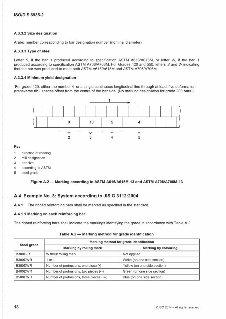
For grade 420, either the number 4 or a single continuous longitudinal line through at least five deformation (transverse rib) spaces offset from the centre of the bar side. (No marking designation for grade 280 bars.)
Key
1 direction of reading 2 mill designation 3 bar size 4 according to ASTM 5 steel grade
Figure A.2 — Marking according to ASTM A615/A615M-13 and ASTM A706/A706M-13
A.4 Example No. 3: System according to JIS G 3112:2004
A.4.1 The ribbed reinforcing bars shall be marked as specified in the standard.
A.4.1.1 Marking on each reinforcing bar
The ribbed reinforcing bars shall indicate the markings identifying the grade in accordance with Table A.2.
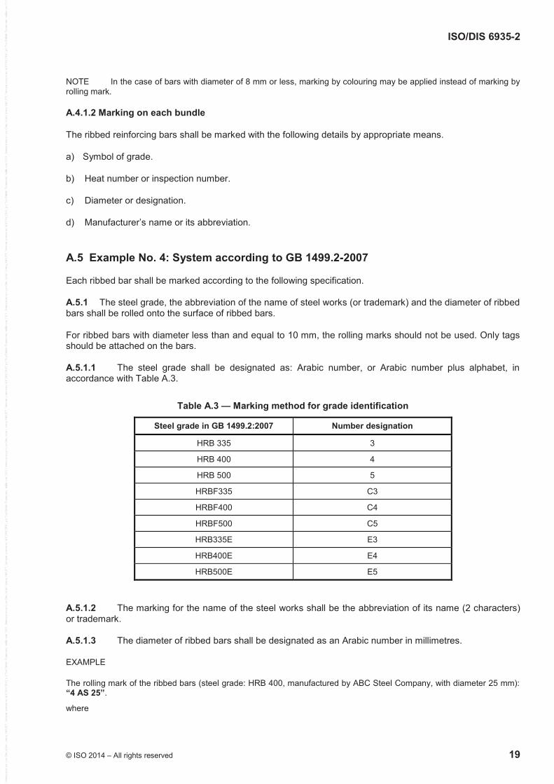
Table A.2 — Marking method for grade identification
Steel grade Marking method for grade identification
Marking by rolling mark Marking by colouring
B300D-R Without rolling mark Not applied
B300DWR 1 or White (on one side section)
B350DWR Number of protrusions, one piece (•) Yellow (on one side section)
B400DWR Number of protrusions, two pieces (••) Green (on one side section)
B500DWR Number of protrusions, three pieces (•••) Blue (on one side section)
ISO/DIS 6935-2
© ISO 2014 – All rights reserved 19
NOTE In the case of bars with diameter of 8 mm or less, marking by colouring may be applied instead of marking by rolling mark.
A.4.1.2 Marking on each bundle
The ribbed reinforcing bars shall be marked with the following details by appropriate means.
a) Symbol of grade.
b) Heat number or inspection number.
c) Diameter or designation.
d) Manufacturer’s name or its abbreviation.
A.5 Example No. 4: System according to GB 1499.2-2007
Each ribbed bar shall be marked according to the following specification.
A.5.1 The steel grade, the abbreviation of the name of steel works (or trademark) and the diameter of ribbed bars shall be rolled onto the surface of ribbed bars.
For ribbed bars with diameter less than and equal to 10 mm, the rolling marks should not be used. Only tags should be attached on the bars.
A.5.1.1 The steel grade shall be designated as: Arabic number, or Arabic number plus alphabet, in accordance with Table A.3.
Table A.3 — Marking method for grade identification
Steel grade in GB 1499.2:2007 Number designation
HRB 335 3
HRB 400 4
HRB 500 5
HRBF335 C3
HRBF400 C4
HRBF500 C5
HRB335E E3
HRB400E E4
HRB500E E5
A.5.1.2 The marking for the name of the steel works shall be the abbreviation of its name (2 characters) or trademark.
A.5.1.3 The diameter of ribbed bars shall be designated as an Arabic number in millimetres.
EXAMPLE
The rolling mark of the ribbed bars (steel grade: HRB 400, manufactured by ABC Steel Company, with diameter 25 mm): “4 AS 25”.
where
ISO/DIS 6935-2
20 © ISO 2014 – All rights reserved
“4” is the steel grade: HRB 400
“AS” is the steel works: ABC Steel Company
“25” is the diameter: 25 mm
ISO/DIS 6935-2
© ISO 2014 – All rights reserved 21
Annex B (informative)
Options for agreement between the manufacturer and purchaser
For convenience, the provisions for which this part of ISO 6935 indicates that additional or deviating requirements can be agreed between the manufacturer and purchaser are listed below. The list does not imply any restriction on agreements concerning other provisions.
a) Diameter 50 mm (Table 2 and Clause 9).
b) Delivery length (Clause 5).
c) Longitudinal ribs (Clause 6).
d) Specified minimum/maximum values (8.1 and 12.3.3).
e) Rebending properties (8.3).
f) Fatigue properties (8.4).
g) Organization of delivery testing (12.3.2.1).
ISO/DIS 6935-2
22 © ISO 2014 – All rights reserved
Bibliography
[1] ISO 3534-1, Statistics — Vocabulary and symbols — Part 1: General statistical terms and terms used in probability
[2] ISO 16020, Steel for the reinforcement and prestressing of concrete — Vocabulary
[3] ISO/IEC Guide 2, Standardization and related activities — General vocabulary