Embed Size (px)
Citation preview

DOCKET NO. 449 – Message Center Management and New Cingular Wireless PCS, LLC application for a Certificate of Environmental Compatibility and Public Need for the construction, maintenance, and operation of a telecommunications facility located at Redding Tax Assessor Map 23, Lot 72, Redding Ridge Fire Department, 186 Black Rock Turnpike, Redding, Connecticut.
} } }
Connecticut
Siting
Council
October 9, 2014
DRAFT Findings of Fact
Introduction
1. Message Center Management, Inc. (MCM) and New Cingular Wireless PCS, LLC (AT&T) collectively
referred to as the Applicant (Applicant), in accordance with provisions of Connecticut General Statutes (C.G.S.) § 16-50g, et seq, applied to the Connecticut Siting Council (Council) on May 19, 2014 for a Certificate of Environmental Compatibility and Public Need (Certificate) for the construction, maintenance, and operation of a 150-foot wireless telecommunications facility at 186 Black Road Turnpike, in Redding, Connecticut. The monopole would replace an existing 80-foot lattice tower at the Redding Ridge Fire District 1 (RRFD). (Applicant 1 pp. i, 1-4)
2. Sprint previously received Council approval on October 16, 2007 to replace the existing 80-foot lattice
tower with a 121-foot 6-inch (or approximately 120-foot) monopole in Docket No. 334. However, such replacement tower was never constructed, and Sprint’s Certificate expired. Thus, the RRFD’s lattice tower remains in use. (Applicant 1, p. 1 and Tab 10; Council Administrative Notice Item No. 334)
3. MCM is a Connecticut corporation with offices at 40 Woodland Street, Hartford, Connecticut. MCM
owns and/or operates numerous facilities in the State of Connecticut. MCM would be the Certificate Holder and would be responsible to construct, maintain and own the proposed tower facility. (Applicant 1, pp. 2-3)
4. AT&T is a Delaware limited liability company with an office at 500 Enterprise Drive, Rocky Hill,
Connecticut. The company’s member corporation is licensed by the Federal Communications Commission (FCC) to construct and operate a personal wireless services system. The company does not conduct any other business in the State of Connecticut other than the provision of wireless services under FCC rules and regulations. (AT&T 2, p. 3)
5. Cellco Partnership d/b/a Verizon Wireless is also a FCC-licensed provider of wireless services in
Connecticut. (Cellco 1) 6. The party in this proceeding is the Applicant. The intervenor in this proceeding is Cellco. (Transcript 1-
3:05 p.m. [Tr. 1], pp. 5) 7. The purpose of the proposed facility is to provide wireless services in the vicinity of Blackrock Turnpike
and to other local roads, schools, and homes in the surrounding Redding Ridge area. (Applicant 1, p. i)
8. AT&T and Cellco each have lease agreements with MCM to co-locate on the proposed tower. (Applicant 1, p. 1; Tr. 3, p. 193)
9. Pursuant to C.G.S. § 16-50l(b), public notice of the application was published in the Redding Pilot on
April 10 and April 17, 2014. (Applicant 1, p. 5 and Tab 7)
10. Pursuant to C.G.S. § 16-50l(b), notice of the application was provided to all abutting property owners by certified mail. Confirmation of delivery was received from all notices sent to abutting property owners. (Applicant 1, p. 5 and Tab 7; Applicant 2, response 3)

Docket No. 449
Findings of Fact
Page 2
11. Pursuant to C.G.S. § 16-50l(b), the Applicant provided notice to all federal, state and local officials and
agencies listed therein. (Applicant 1, p. 5 and Tab 8) 12. Pursuant to C.G.S. §16-50gg, upon receipt of the application, the Council sent a letter to Town of
Redding on May 19, 2014 as notification that the application was received and is being processed. (record)
13. Pursuant to C.G.S. §16-50m, the Council published legal notice of the date and time of the public hearing in the Redding Pilot on June 19, 2014. (record)
14. Pursuant to R.C.S.A. §16-50j-21, the Applicant installed a four-foot by six-foot sign at the entrance of
the subject property on June 10, 2014. The sign presented information regarding the project and the Council’s public hearing. (Applicant 5)
15. The Council and its staff conducted an inspection of the proposed site on July 29, 2014, beginning at 2:00 p.m. During the field inspection, the Applicant flew a red 4-foot diameter balloon at the proposed site to simulate the height of the proposed tower. Weather conditions were not ideal. Wind speeds were approximately seven to ten miles per hour. The balloon was tethered to reach a height of 150 feet above ground level (AGL), but it was getting pushed over to lower heights by the winds. One balloon was lost, but it was replaced. The balloons were aloft from 7:45 a.m. to 6:00 p.m. for the convenience of the public. (Council’s Hearing Notice dated June 16, 2014; Tr. 1, pp. 13-14)
16. Pursuant to C.G.S. § 16-50m, the Council, after giving due notice thereof, held a public hearing on July
29, 2014, beginning with the evidentiary portion of the hearing at 3:00 p.m. and continuing with the public comment session at 7:00 p.m. at the Redding Community Center, Community Room, 37 Lonetown Road, Redding, Connecticut. (Council's Hearing Notice dated June 16, 2014; Tr. 1, p. 1; Transcript 2 – 7:00 p.m. [Tr. 2], p. 116)
17. The Council held a continued public hearing on September 9, 2014, beginning at 1:02 p.m. at 10
Franklin Square, New Britain, Connecticut. (Council’s Hearing Continued Hearing Memo dated July 30, 2014; Transcript 3 – 1:02 p.m. [Tr. 3], p. 158)
State Agency Comment
18. Pursuant to C.G.S. § 16-50j (g), on June 16, 2014 and September 10, 2014, the following State agencies
were solicited by the Council to submit written comments regarding the proposed facility: Department of Energy and Environmental Protection (DEEP); Department of Public Health (DPH); Council on Environmental Quality (CEQ); Public Utilities Regulatory Authority (PURA); Office of Policy and Management (OPM); Department of Economic and Community Development (DECD); Department of Agriculture (DOAg); Department of Transportation (DOT); Connecticut Airport Authority (CAA); State Historic Preservation Office (SHPO); and Department of Emergency Services and Public Protection (DESPP). (Record)
19. The Council received responses from the DOT’s Bureau of Engineering and Highway Construction on June 26, 2014 and July 1, 2014, and from the DPH on June 27, 2014. (DOT Comments dated June 26, 2014 and July 1, 2014; DPH Comments dated June 27, 2014)
20. In its comments, DOT determined that construction work would only be performed on the subject property of RRFD. Thus, an encroachment permit would not be required. (DOT Comments dated July 1, 2014)

Docket No. 449
Findings of Fact
Page 3
21. In its comments, DPH noted that the project is located within Aquarion Water Compnay’s (AWC)
Hemlock Reservoir Watershed, an active source of public drinking water. Thus, the Drinking Water Section (DWS) of DPH offered the following recommendations to protect this source of drinking water:
a) Erosion and sedimentation controls should be in place and properly maintained as necessary; b) A responsible party should be identified for maintenance, inspection, repair, and replacement
and incorporation of new controls as may become necessary; c) Servicing of machinery should be completed outside of the public water supply watershed; d) Refueling of vehicles or machinery should take place on an impervious pad with secondary
containment designed to contain fuels; e) Fuel and other hazardous materials should not be stored within the public water supply
watershed; f) Any fuel or hazardous materials that must be kept within the public water supply watershed
during working hours should be stored on an impervious surface utilizing secondary containment;
g) A fuel spill remediation kit should be stored on-site so that any spills may be contained and cleaned quickly; and
h) AWC should be contacted prior to starting this project to review the scope of the project. i) AWC personnel should be allowed to periodically inspect this project to ensure that drinking
water quality is not adversely impacted. (DPH Comments dated June 27, 2014)
22. The following agencies did not respond with comment on the application: DEEP, CEQ, PURA, OPM,
DECD, DOAg, CAA, SHPO, and DESPP. (Record)
Municipal Consultation
23. MCM, working together with AT&T, pursued a lease with the RRFD. (Applicant 1, p. 28) 24. After approval of the lease, the Applicants forwarded a Technical Report to the Town of Redding on
December 31, 2013. (Applicant 1, p. 28) 25. The Town of Redding requested a public information meeting to review the Technical Report. This
meeting was publically noticed in the Redding Pilot and a copy of the notice was also sent to the abutting property owners. (Applicant 1, p. 28)
26. At the March 4, 2014 public information meeting, the Applicant’s representatives provided an overview
of AT&T’s needs in the area and details of the proposed facility to attending interested citizens and municipal officials. (Applicant 1, p. 28)
27. No further consultation or information was requested by the public or Redding. (Applicant 1, p. 28)
28. In its written comments, The Redding Planning Commission notes that with the RRFD antennas at 85
feet and with 20-foot spacing, the viability of a 110-foot tower should be considered. Specifically, the Redding Planning Commission requested that the Council:
a) Withhold permitting pending review of a coverage map for 110 feet and a careful assessment of the true coverage benefit gained by the excess height; and
b) Disallow any excess height request based on purely speculative future tenancy concepts beyond that required by the confirmed AT&T and Verizon tenancies and the justified needs of the public.
(Redding Planning Commission Comments dated June 12, 2014)

Docket No. 449
Findings of Fact
Page 4
29. Julia Pemberton, First Selectman for the Town of Redding (Town), made a limited appearance statement
at the July 29, 2014 hearing. First Selectman Pemberton noted that the Town recognizes a need for additional cell coverage in this portion of Redding to fill a void and enhance public safety. The Board of Selectman did not take a position on what the appropriate height of the tower should be. However, First Selectman Pemberton requested that the Council consider a 120-foot tower height versus the proposed tower height of 150 feet to protect the rural character of the community and not to “overbuild.” First Selectman Pemberton noted that the tower should be designed for the needs of today; it could be expanded in the future if necessary, but the Council should require the Applicant to do whatever is necessary to mitigate the visual impact on the community. (Tr. 2, pp. 153-155)
30. Ben Pardee, Fire Commissioner for RRFD, gave a limited appearance statement at the public hearing
and indicated the following:
a) The RRFD supports the proposed replacement 150-foot cell tower because it would provide for both a daily convenience of good service to the taxpayers and the best service for any homeowner, motorist, or outdoorsman who may need to summon emergency help by phone;
b) The RRFD’s 20,000-gallon underground water storage tank is old, and the RRFD is open to the
discussion of its replacement and relocation. The 2,000-gallon underground propane storage tank is seven years old and is properly installed and inspected. It could be relocated if necessary; and
c) The RRFD supports a permanent standby generator solution for the cell site and is willing to
consider any reasonable proposal regarding generators and fuel sharing. (Tr. 2, pp. 131-132)
31. MCM would provide space on the tower for the Town’s emergency communication services. To date,
the Town has only expressed an interest in re-locating the RRFD’s existing antennas from the existing tower to the new tower. (Tr. 1, pp. 15-16; Applicant 1, Tab 3 – Sheet SP-3)
Public Need for Service
32. In 1996, the United States Congress recognized a nationwide need for high quality wireless telecommunications services, including cellular telephone service. Through the Federal Telecommunications Act of 1996, Congress seeks to promote competition, encourage technical innovations, and foster lower prices for telecommunications services. (Council Administrative Notice Item No. 4 – Telecommunications Act of 1996)
33. In issuing cellular licenses, the Federal government has preempted the determination of public need for cellular service by the states, and has established design standards to ensure technical integrity and nationwide compatibility among all systems. AT&T and Cellco are licensed by the Federal Communications Commission (FCC) to provide personal wireless communication service to Fairfield County, Connecticut. (Council Administrative Notice Item No. 4 – Telecommunications Act of 1996; Applicant 1, p. 3; Applicant 2, response 19; Cellco 1, p. 1)
34. Section 253 of the Telecommunications Act of 1996 prohibits any state or local statute or regulation, or other state or local legal requirement from prohibiting or having the effect of prohibiting the ability of any entity to provide any interstate or intrastate telecommunications service. (Council Administrative Notice Item No.4 – Telecommunications Act of 1996)
Docket No. 449
Findings of Fact
Page 5
35. Section 332 of the Telecommunications Act of 1996 prohibits local and state entities from discriminating
among providers of functionally equivalent services and from prohibiting or having the effect of prohibiting the provision of personal wireless services. This section also requires state or local governments to act on applications within a reasonable period of time and to make any denial of an application in writing supported by substantial evidence in a written record. (Council Administrative Notice Item No. 4 – Telecommunications Act of 1996)
36. Section 332 of the Telecommunications Act of 1996 also prohibits any state or local entity from
regulating telecommunications towers on the basis of the environmental effects, which include effects on human health and wildlife, of radio frequency emissions to the extent that such towers and equipment comply with FCC’s regulations concerning such emissions.(Council Administrative Notice Item No. 4 – Telecommunications Act of 1996)
37. In February 2009, as part of the American Recovery and Reinvestment Act, Congress directed the FCC
to develop a National Broadband Plan to ensure every American has “access to broadband capability.” Congress also required that this plan include a detailed strategy for achieving affordability and maximizing use of broadband to advance “consumer welfare, civic participation, public safety and homeland security, community development, health care delivery, energy independence and efficiency, education, employee training, private sector investment, entrepreneurial activity, job creation and economic growth, and other national purposes.”(The National Broadband Plan - Council Administrative Notice Item No. 19)
38. Section 706 of the Telecommunications Act of 1996 requires each state commission with regulatory
jurisdiction over telecommunications services to encourage the deployment on a reasonable and timely basis of advanced telecommunications capability to all Americans, including elementary and secondary schools, by utilizing regulating methods that promote competition in the local telecommunications market and remove barriers to infrastructure investment. (Council Administrative Notice Item No. 4 – Telecommunications Act of 1996)
39. In December 2009, President Barack Obama recognized cell phone towers as critical infrastructure vital
to the United States. The Department of Homeland Security, in collaboration with other Federal stakeholders, State, local, and tribal governments, and private sector partners, has developed the National Infrastructure Protection Plan (NIPP) to establish a framework for securing our resources and maintaining their resilience from all hazards during an event or emergency. (Council Administrative Notice Item No. 11 – Barack Obama Presidential Proclamation 8460, Critical Infrastructure Protection)
40. In February 2012, Congress adopted the Middle Class Tax Relief and Job Creation Act to advance wireless broadband service for both public safety and commercial users. The Act established the First Responder Network Authority to oversee the construction and operation of a nationwide public safety wireless broadband network. Section 6409 of the Act contributes to the twin goals of commercial and public safety wireless broadband deployment through several measures that promote rapid deployment of the network facilities needed for the provision of broadband wireless services. (Council Administrative Notice Item No. 8 – Middle Class Tax Relief and Job Creation Act of 2012)
41. Pursuant to Section 6409(a) of the Middle Class Tax Relief and Job Creation Act of 2012, a state or local government may not deny and shall approve any request for collocation, removal or replacement of equipment on an existing wireless tower provided that this does not constitute a substantial change in the physical dimensions of the tower. The Federal Communications Commission defines a substantial change in the physical dimensions of a tower as follows:
a) The mounting of the proposed antenna on the tower would increase the existing height of the tower
by more than 10% or by the height of one additional antenna array with separation from the nearest

Docket No. 449
Findings of Fact
Page 6
existing antenna not to exceed twenty feet, whichever is greater, except that the mounting of the proposed antenna may exceed the size limits if necessary to avoid interference with existing antennas; or
b) The mounting of the proposed antenna would involve the installation of more than the standard number of new equipment cabinets for the technology involved, not to exceed four, or more than one new equipment shelter; or
c) The mounting of the proposed antenna would involve adding an appurtenance to the body of the tower that would protrude from the edge of the tower more than twenty feet, or more than the width of the tower structure at the level of the appurtenance, whichever is greater, except that the mounting of the proposed antenna may exceed the size limits if necessary to shelter the antenna from inclement weather or to connect the antenna to the tower via cable; or
d) The mounting of the proposed antenna would involve excavation outside the current tower site, defined as the current boundaries of the leased or owned property surrounding the tower and any access or utility easements currently related to the site.
(Council Administrative Notice Item No. 8 – Middle Class Tax Relief and Job Creation Act of 2012, Pub. L. No. 112-96, §6409 Wireless Facilities Deployment (2012), available at http://www.gpo.gov/fdsys/pkg/PLAW-112publ96/pdf/PLAW-112publ96.pdf and FEDERAL
COMMUNICATIONS COMMISSION, Public Notice – Wireless Telecommunications Bureau Offers Guidance on Interpretation of Section 6409(a) of the Middle Class Tax Relief and Job Creation Act of 2012, DA 12-2407, January 25, 2013)
42. Pursuant to the tower-sharing policy of the State of Connecticut under C.G.S. §16-50aa, if the Council
finds that a request for shared use of a facility by a municipality or other person, firm, corporation or public agency is technically, legally, environmentally and economically feasible, and the Council finds that the request for shared use of a facility meets public safety concerns, the Council shall issue an order approving such shared use to avoid the unnecessary proliferation of towers in the state. (Conn. Gen. Stat. §16-50aa)
Existing and Proposed Wireless Coverage – AT&T
43. AT&T’s proposed facility is primarily needed for coverage, but would also improve capacity in the area. (Tr. 1, pp. 82-83)
44. AT&T would provide service over 700 MHz, 850 MHz, and 1900 MHz frequency bands. 700 MHz and
850 MHz would be primarily for coverage, and 1900 MHz would provide extra capacity. All three bands would be used for voice and data. All three bands would be on air when the site enters service. (Applicant 2, responses 20, 21, and 22)
45. For 700 MHz, AT&T’s design signal strengths for in-building and in-vehicle coverage are -83 dBm and
-93 dBm, respectively. For 850 MHz, the design signal strengths for in-building and in-vehicle coverage are -74 and -82 dBm, respectively. For 1900 MHz, the design signal strengths for in-building and in-vehicle coverage are -86 dBm and -96 dBm, respectively. (Applicant 2, response 24)
46. For 700 MHz, AT&T’s existing signal strength in the area of the proposed facility ranges from -93 dBm to -120 dBm. For 1900 MHz, AT&T’s existing signal strength ranges from -96 dBm to -120 dBm. (Applicant 2, response 25)

Docket No. 449
Findings of Fact
Page 7
47. The table below indicates AT&T’s current coverage gaps along main routes.
Street Name Coverage Gap
at 700 MHz
Coverage Gap
at 850 MHz*
Coverage Gap
at 1900 MHz
Black Rock Turnpike 5.65 miles N/A 5.65 miles
Dodgingtown Road 0.82 miles N/A 0.82 miles
Pinetree Road 0.69 miles N/A 0.69 miles
Rock House Road 3.15 miles N/A 3.15 miles
Sport Hill Road 2.98 miles N/A 2.98 miles
Route 58 3.43 miles N/A 5.70 miles
Total 16.74 miles 11.14 miles 19.01 miles
*Only the total or sum of the 850 MHz main route coverage gaps was provided. (Applicant 2, response 30; Applicant 3, response 52 – Attachment 2)
48. The table below indicates AT&T’s current coverage gaps along secondary routes.
Street Name Coverage Gap
at 700 MHz
Coverage Gap
at 850 MHz
Coverage Gap
At 1900 MHz
Secondary Road Total
70.58 miles 54.77 miles 89.35 miles
(Applicant 2, response 30) 49. The tables below indicate the distances that AT&T would cover along main roads in the area of its
proposed facility at various heights.
Street Name 700 MHz Coverage at 150
feet
700 MHz Coverage at 140
feet
700 MHz Coverage at 130
feet
700 MHz Coverage at 120
feet
Black Rock Tpke. 0.23 miles 0.17 miles 0.1 miles 0.08 miles
Church Hill Road 0.35 miles 0.34 miles 0.36 miles 0.31 miles
Lonetown Road None None None None
Hattertown Road None None None None
Maple Road 0.01 miles None None None
Newtown Tpke. 0.41 miles 0.39 miles 0.1 miles 0.08 miles
Pinetree Road None None None None
Redding Road None None None None
Rock House Road 0.41 miles 0.41 miles 0.38 miles 0.32 miles
Sport Hill Road 0.65 miles 0.65 miles 0.57 miles 0.48 miles
Route 107 None None None None
Route 58 1.44 miles 1.37 miles 1.00 miles 0.85 miles
Stepney Road 0.05 miles 0.02 miles None None
Westport Road None None None None
Main Road Total
3.55 miles 3.35 miles 2.51 miles 2.12 miles

Docket No. 449
Findings of Fact
Page 8
Street Name 850 MHz Coverage at 150
feet
850 MHz Coverage at 140
feet
850 MHz Coverage at 130
feet
850 MHz Coverage at 120
feet
Black Rock Tpke. 1.11 miles 1.02 miles 0.73 miles 0.50 miles
Church Hill Road None None None 0.13 miles
Lonetown Road None None None None
Hattertown Rd. 0.70 miles 0.50 miles 0.15 miles 0.13 miles
Maple Road None None 0.03 miles 0.03 miles
Newtown Tpke. N/A 0.02 miles 0.29 miles 0.26 miles
Pinetree Road 0.30 miles 0.23 miles 0.30 miles 0.29 miles
Redding Road None None 0.12 miles 0.11 miles
Rock House Rd. 0.27 miles 0.20 miles 0.17 miles 0.17 miles
Sport Hill Road 0.47 miles 0.14 miles 0.50 miles 0.49 miles
Route 107 0.14 miles 0.14 miles 0.04 miles 0.02 miles
Route 58 0.90 miles 0.64 miles 0.33 miles 0.33 miles
Stepney Road 0.17 miles 0.04 miles 0.18 miles 0.17 miles
Westport Road 0.98 miles 0.19 miles 0.19 miles 0.20 miles
Main Road Total
5.04 miles 3.12 miles 3.03 miles 2.83 miles
Street Name 1900 MHz Coverage at 150
feet
1900 MHz Coverage at 140
feet
1900 MHz Coverage at 130
feet
1900 MHz Coverage at 120
feet
Black Rock Tpke. 0.23 miles 0.21 miles 0.06 miles 0.06 miles
Church Hill Rd. 0.32 miles 0.32 miles 0.34 miles 0.32 miles
Lonetown Road None None 0.03 miles 0.03 miles
Hattertown Road None None None None
Maple Road None None None None
Newtown Tpke. 0.31 miles 0.28 miles 0.04 miles 0.04 miles
Pinetree Road None None None None
Redding Road None None None None
Rock House Road None None 0.02 miles 0.02 miles
Sport Hill Road 0.47 miles 0.45 miles 0.48 miles 0.45 miles
Route 107 None None None None
Route 58 1.16 miles 1.16 miles 1.10 miles 1.04 miles
Stepney Road 0.12 miles 0.08 miles None None
Westport Road None None None None
Main Road Total
2.61 miles 2.50 miles 2.07 miles 1.96 miles
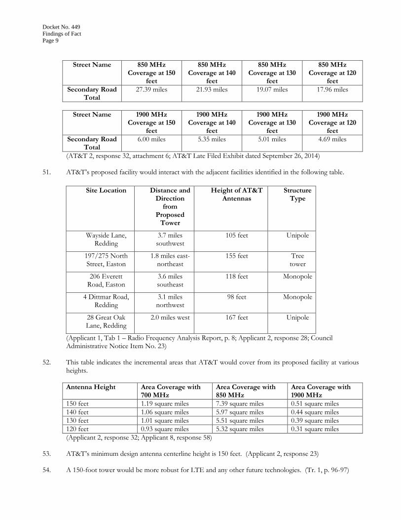
(Applicant 2, response 32, attachment 6; Applicant Late Filed Exhibit dated September 26, 2014) 50. The tables below indicate the distances that AT&T would cover along secondary roads in the area of its
proposed facility at various heights.
Street Name 700 MHz Coverage at 150
feet
700 MHz Coverage at 140
feet
700 MHz Coverage at 130
feet
700 MHz Coverage at 120
feet
Secondary Road Total
7.46 miles 6.94 miles 6.03 miles 5.72 miles
Docket No. 449
Findings of Fact
Page 9
Street Name 850 MHz Coverage at 150
feet
850 MHz Coverage at 140
feet
850 MHz Coverage at 130
feet
850 MHz Coverage at 120
feet
Secondary Road Total
27.39 miles 21.93 miles 19.07 miles 17.96 miles
Street Name 1900 MHz Coverage at 150
feet
1900 MHz Coverage at 140
feet
1900 MHz Coverage at 130
feet
1900 MHz Coverage at 120
feet
Secondary Road Total
6.00 miles 5.35 miles 5.01 miles 4.69 miles
(AT&T 2, response 32, attachment 6; AT&T Late Filed Exhibit dated September 26, 2014)
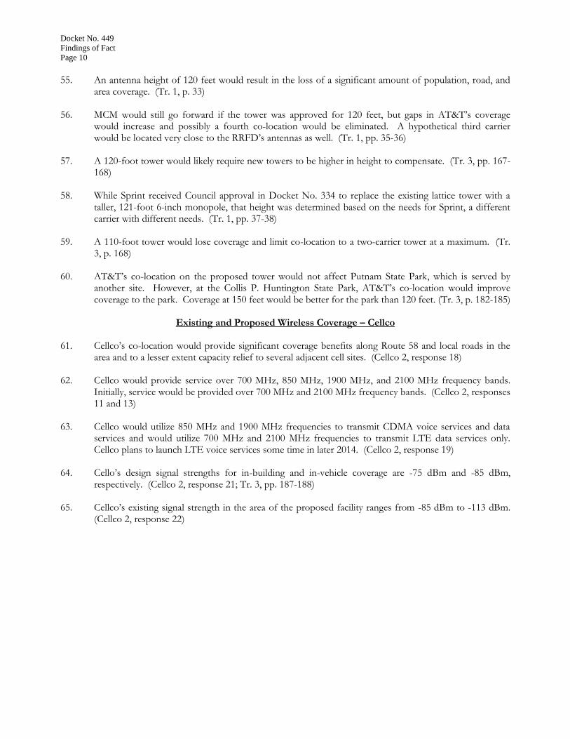
51. AT&T’s proposed facility would interact with the adjacent facilities identified in the following table.
Site Location Distance and Direction
from Proposed
Tower
Height of AT&T Antennas
Structure Type
Wayside Lane, Redding
3.7 miles southwest
105 feet Unipole
197/275 North Street, Easton
1.8 miles east-northeast
155 feet Tree tower
206 Everett Road, Easton
3.6 miles southeast
118 feet Monopole
4 Dittmar Road, Redding
3.1 miles northwest
98 feet Monopole
28 Great Oak Lane, Redding
2.0 miles west 167 feet Unipole
(Applicant 1, Tab 1 – Radio Frequency Analysis Report, p. 8; Applicant 2, response 28; Council Administrative Notice Item No. 23)
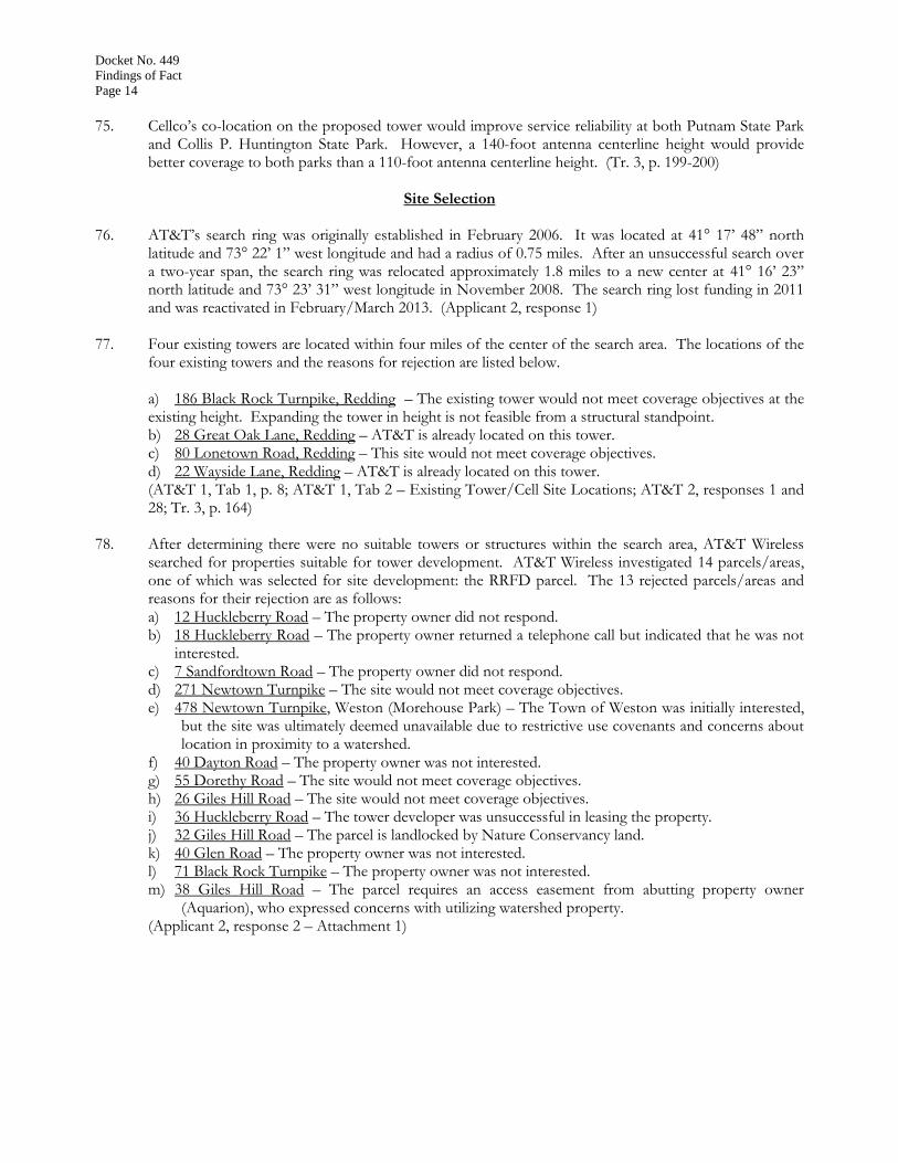
52. This table indicates the incremental areas that AT&T would cover from its proposed facility at various heights.
Antenna Height Area Coverage with 700 MHz
Area Coverage with 850 MHz
Area Coverage with 1900 MHz
150 feet 1.19 square miles 7.39 square miles 0.51 square miles
140 feet 1.06 square miles 5.97 square miles 0.44 square miles
130 feet 1.01 square miles 5.51 square miles 0.39 square miles
120 feet 0.93 square miles 5.32 square miles 0.31 square miles
(Applicant 2, response 32; Applicant 8, response 58)
53. AT&T’s minimum design antenna centerline height is 150 feet. (Applicant 2, response 23) 54. A 150-foot tower would be more robust for LTE and any other future technologies. (Tr. 1, p. 96-97)
Docket No. 449
Findings of Fact
Page 10
55. An antenna height of 120 feet would result in the loss of a significant amount of population, road, and
area coverage. (Tr. 1, p. 33) 56. MCM would still go forward if the tower was approved for 120 feet, but gaps in AT&T’s coverage
would increase and possibly a fourth co-location would be eliminated. A hypothetical third carrier would be located very close to the RRFD’s antennas as well. (Tr. 1, pp. 35-36)
57. A 120-foot tower would likely require new towers to be higher in height to compensate. (Tr. 3, pp. 167-
168) 58. While Sprint received Council approval in Docket No. 334 to replace the existing lattice tower with a
taller, 121-foot 6-inch monopole, that height was determined based on the needs for Sprint, a different carrier with different needs. (Tr. 1, pp. 37-38)
59. A 110-foot tower would lose coverage and limit co-location to a two-carrier tower at a maximum. (Tr.
3, p. 168) 60. AT&T’s co-location on the proposed tower would not affect Putnam State Park, which is served by
another site. However, at the Collis P. Huntington State Park, AT&T’s co-location would improve coverage to the park. Coverage at 150 feet would be better for the park than 120 feet. (Tr. 3, p. 182-185)
Existing and Proposed Wireless Coverage – Cellco
61. Cellco’s co-location would provide significant coverage benefits along Route 58 and local roads in the
area and to a lesser extent capacity relief to several adjacent cell sites. (Cellco 2, response 18) 62. Cellco would provide service over 700 MHz, 850 MHz, 1900 MHz, and 2100 MHz frequency bands.
Initially, service would be provided over 700 MHz and 2100 MHz frequency bands. (Cellco 2, responses 11 and 13)
63. Cellco would utilize 850 MHz and 1900 MHz frequencies to transmit CDMA voice services and data
services and would utilize 700 MHz and 2100 MHz frequencies to transmit LTE data services only. Cellco plans to launch LTE voice services some time in later 2014. (Cellco 2, response 19)
64. Cello’s design signal strengths for in-building and in-vehicle coverage are -75 dBm and -85 dBm,
respectively. (Cellco 2, response 21; Tr. 3, pp. 187-188)
65. Cellco’s existing signal strength in the area of the proposed facility ranges from -85 dBm to -113 dBm. (Cellco 2, response 22)

Docket No. 449
Findings of Fact
Page 11
66. The table below indicates Cellco’s current coverage gaps along main routes.
Street Name Coverage Gap
at 700 MHz
Coverage Gap
at 850 MHz
Coverage Gap
At 1900 MHz
Coverage Gap at
2100 MHz
Black Rock Turnpike (Route
58)
3.65 miles 3.65 miles 3.65 miles 3.65 miles
Cross Highway 2.25 miles 2.25 miles 2.25 miles 2.25 miles
Total 5.90 miles 5.90 miles 5.90 miles 5.90 miles
(Cellco 2, response 26)
67. The table below indicates Cellco’s current coverage gaps along secondary routes.
Street Name Coverage Gap
at 700 MHz
Coverage Gap
at 850 MHz
Coverage Gap
At 1900 MHz
Coverage Gap at
2100 MHz
Secondary Road Total
2.85 miles 3.14 miles 4.84 miles 5.02 miles
(Cellco 2, response 27) 68. The tables below indicate the distances that Cellco would cover along main roads in the area of its
proposed facility at various heights.
Street Name 700 MHz Coverage at 140
feet
700 MHz Coverage at 120
feet
700 MHz Coverage at 110
feet
Black Rock Tpke. 2.42 miles 2.21 miles 2.10 miles
Cross Highway 0.42 miles 0.42 miles 0.42 miles
Main Road Total
2.84 miles 2.52 miles 2.52 miles
Street Name 850 MHz Coverage at 140
feet
850 MHz Coverage at 120
feet
850 MHz Coverage at 110
feet
Black Rock Tpke. 2.20 miles 2.00 miles 1.92 miles
Cross Highway 0.35 miles 0.35 miles 0.35 miles
Main Road Total
2.55 miles 2.35 miles 2.27 miles

Docket No. 449
Findings of Fact
Page 12
Street Name 1900 MHz Coverage at 140
feet
1900 MHz Coverage at 120
feet
1900 MHz Coverage at 110
feet
Black Rock Tpke. 1.94 miles 1.77 miles 1.69 miles
Cross Highway 0.30 miles 0.30 miles 0.30 miles
Main Road Total
2.24 miles 2.07 miles 1.99 miles
Street Name 2100 MHz Coverage at 140
feet
2100 MHz Coverage at 120
feet
2100 MHz Coverage at 110
feet
Black Rock Tpke. 1.85 miles 1.69 miles 1.61 miles
Cross Highway 0.30 miles 0.30 miles 0.30 miles
Main Road Total
2.15 miles 1.99 miles 1.91 miles
(Cellco 2, response 28; Cellco 4, response 45) 69. The tables below indicate the distances that Cellco would cover along secondary roads in the area of its
proposed facility at various heights.
Street Name 700 MHz Coverage at 140
feet
700 MHz Coverage at 120
feet
700 MHz Coverage at 110
feet
Secondary Road Total
9.20 miles 6.90 miles 6.00 miles
Street Name 850 MHz Coverage at 140
feet
850 MHz Coverage at 120
feet
850 MHz Coverage at 110
feet
Secondary Road Total
6.95 miles 5.40 miles 4.50 miles
Street Name 1900 MHz Coverage at 140
feet
1900 MHz Coverage at 120
feet
1900 MHz Coverage at 110
feet
Secondary Road Total
5.40 miles 4.20 miles 3.50 miles
Street Name 2100 MHz Coverage at 140
feet
2100 MHz Coverage at 120
feet
2100 MHz Coverage at 110
feet
Secondary Road Total
5.05 miles 3.90 miles 3.30 miles
(Cellco 2, response 29; Cellco 4, response 46)

Docket No. 449
Findings of Fact
Page 13
70. Cellco’s proposed facility would interact with the adjacent facilities identified in the following table.
Site Location Distance and Direction from Proposed Tower
Height of Cellco Antennas
Structure Type
197/275 North Street, Easton
1.8 miles northeast
165 feet Tree tower
80 Lonetown Road, Redding
2.25 miles northwest
90 feet Lattice tower
100 Old Redding Road, Redding
5.0 miles southwest
172 feet Lattice tower
237 Godfrey Road, Weston
5.0 miles south-
southwest
165 feet Lattice tower
206 Everett Road, Easton
3.6 miles southeast
128 feet Monopole
(Cellco 2, response 17; Council Administrative Notice Item No. 23)
71. The table indicates the areas that Cellco would cover from its proposed facility at various heights.
Antenna Height Area Coverage with 700 MHz
Area Coverage with 850 MHz
Area Coverage with 1900 MHz
Area Coverage with 2100 MHz
140 feet 33.56 square miles 17.05 square miles 12.22 square miles 7.80 square miles
130 feet 32.24 square miles 16.25 square miles 11.76 square miles 7.50 square miles
120 feet 31.07 square miles 15.36 square miles 9.40 square miles 7.31 square miles
110 feet 29.59 square miles 14.35 square miles 9.02 square miles 7.01 square miles
(Cellco 2, response 30; Cellco 4, response 47; Tr. 3, pp. 188)
72. Cellco’s minimum design antenna height is 120 feet, but Cellco proposes to install its antennas at the highest available location under AT&T, which would be 140 feet. Notwithstanding, Cellco would accept any height on the tower because it is the only structure in the area. (Tr. 3, pp. 189-190, 194-195)
73. Neglecting coverage concerns and considering only interference issues, the lowest theoretical centerline
height on the tower that Cellco could locate its antennas and not interfere with the RRFD’s antennas would be 106 feet AGL. (Tr. 3, pp. 190-192)
74. If the tower is approved at 120 feet in height, Cellco would have to locate its antennas at the 110-foot
level of the tower. This would result in a reduced coverage footprint as compared to Cellco’s proposed antenna height of 140 feet. (Tr. 3, p. 190)
Docket No. 449
Findings of Fact
Page 14
75. Cellco’s co-location on the proposed tower would improve service reliability at both Putnam State Park
and Collis P. Huntington State Park. However, a 140-foot antenna centerline height would provide better coverage to both parks than a 110-foot antenna centerline height. (Tr. 3, p. 199-200)
Site Selection
76. AT&T’s search ring was originally established in February 2006. It was located at 41° 17’ 48” north
latitude and 73° 22’ 1” west longitude and had a radius of 0.75 miles. After an unsuccessful search over a two-year span, the search ring was relocated approximately 1.8 miles to a new center at 41° 16’ 23” north latitude and 73° 23’ 31” west longitude in November 2008. The search ring lost funding in 2011 and was reactivated in February/March 2013. (Applicant 2, response 1)
77. Four existing towers are located within four miles of the center of the search area. The locations of the four existing towers and the reasons for rejection are listed below.
a) 186 Black Rock Turnpike, Redding – The existing tower would not meet coverage objectives at the existing height. Expanding the tower in height is not feasible from a structural standpoint. b) 28 Great Oak Lane, Redding – AT&T is already located on this tower. c) 80 Lonetown Road, Redding – This site would not meet coverage objectives. d) 22 Wayside Lane, Redding – AT&T is already located on this tower. (AT&T 1, Tab 1, p. 8; AT&T 1, Tab 2 – Existing Tower/Cell Site Locations; AT&T 2, responses 1 and 28; Tr. 3, p. 164)
78. After determining there were no suitable towers or structures within the search area, AT&T Wireless searched for properties suitable for tower development. AT&T Wireless investigated 14 parcels/areas, one of which was selected for site development: the RRFD parcel. The 13 rejected parcels/areas and reasons for their rejection are as follows: a) 12 Huckleberry Road – The property owner did not respond. b) 18 Huckleberry Road – The property owner returned a telephone call but indicated that he was not
interested. c) 7 Sandfordtown Road – The property owner did not respond. d) 271 Newtown Turnpike – The site would not meet coverage objectives. e) 478 Newtown Turnpike, Weston (Morehouse Park) – The Town of Weston was initially interested,
but the site was ultimately deemed unavailable due to restrictive use covenants and concerns about location in proximity to a watershed.
f) 40 Dayton Road – The property owner was not interested. g) 55 Dorethy Road – The site would not meet coverage objectives. h) 26 Giles Hill Road – The site would not meet coverage objectives. i) 36 Huckleberry Road – The tower developer was unsuccessful in leasing the property. j) 32 Giles Hill Road – The parcel is landlocked by Nature Conservancy land. k) 40 Glen Road – The property owner was not interested. l) 71 Black Rock Turnpike – The property owner was not interested. m) 38 Giles Hill Road – The parcel requires an access easement from abutting property owner
(Aquarion), who expressed concerns with utilizing watershed property. (Applicant 2, response 2 – Attachment 1)

Docket No. 449
Findings of Fact
Page 15
79. Repeaters, microcell transmitters, distributed antenna systems, and other types of transmitting
technologies are not a practicable or feasible means to provide service within the service area for the proposed site. These technologies are better suited for specifically defined areas where new coverage is necessary, such as commercial buildings, shopping malls, and tunnels, or to address capacity. Closing the coverage gaps and providing reliable wireless services in Redding requires a tower site that can provide reliable service over a footprint that spans several thousand acres. (Applicant 1, p. 15;p Tr. 1, pp. 40-41)
Facility Description
80. The proposed site is located on a 0.62-acre parcel owned by RRFD and located at 186 Black Rock Turnpike (Route 58) in Redding. The parcel contains an existing active fire department building. The site location is depicted on Figure 1. (Applicant 1, Tab 3 – Sheet A-1)
81. The property is zoned residential, R-2. (Applicant 1, p. 23; Tr. 1, p. 22)
82. The proposed tower would be located behind the RRFD building in the eastern portion of the property at 41° 18’ 35.8” north latitude and 73° 20’ 51.4” west longitude at an elevation of 636 feet above mean sea level (amsl). (Applicant 1, Tab 3 – Sheets T-1 and A-1)
83. The existing facility (to be removed and replaced) is an approximately 80-foot self-supporting lattice tower owned by the fire department. The total height of the existing tower with the existing concrete piers and anchor bolts is 80-foot 5-inches AGL. (Applicant 1, Tab 3 – Sheet SP-3; Applicant 2, response 11)
84. The proposed replacement facility would consist of a 150-foot monopole. The tower would be four to
five feet wide at the base tapering to approximately 27 to 30 inches at the top. The tower would be designed to support a total of four levels of antennas with a 10-foot center-to-center vertical separation, including AT&T and Cellco. The tower would have a galvanized gray finish. (Applicant 1, Tab 3 – Sheet SP-3; Tr. 1, pp. 22-23)
85. The tower and foundation would not be designed to accommodate an expansion in height over the
proposed 150 feet. (Applicant 2, response 7) 86. The RRFD’s approximately 12-foot tall antennas would be re-located to the approximately 86-foot
centerline height of the proposed tower. The RRFD’s yagi antenna would be re-located to the approximately 45-foot level of the tower. (Tr. 3, p. 168; Applicant 1, Tab 3 – Sheet SP-3)
87. The proposed tower and foundation would be installed prior to relocating the RRFD’s existing antennas
to the new tower. The proposed tower would be located approximately 24 feet to the northeast of the existing tower location. Once the RRFD’s antennas are re-located, the existing 80-foot lattice tower can be decommissioned and removed. The existing tower foundations would be cut flush with the ground level and left in place. (Applicant 1, Tab 3 – Sheet SP-1; Tr. 1, pp. 24-25)
88. AT&T proposes to install 12 panel antennas, 21 remote radio heads (RRHs), and four surge suppressors
on a low-profile platform at the 150-foot level of the tower. The total height of the facility with AT&T’s eight-foot antennas would be 154 feet agl. Cellco proposes to install 12 panel antennas and six RRHs on a low-profile platform at the 140-foot agl level of the tower. (Applicant 1, p. 2; Applicant 1, Tab 3 – Sheet SP-3; Applicant 3, responses 50 and 51; Cellco 2, responses 3 and 4; Tr. 3, p. 187; Applicant 2, response 15)

Docket No. 449
Findings of Fact
Page 16
89. T-arms are an acceptable alternative antenna mount for AT&T and Cellco. (Applicant 2, response 14;
Cellco 2, response 6) 90. In order to flush-mount AT&T’s antennas, it would likely require three positions on the tower with
either increased height or reduced coverage. Moreover, with multiple levels of antennas and other equipment like remote radio heads, flush-mounting antennas is becoming impractical. (Applicant 2, response 14; Tr. 1, pp. 38-39; Tr. 3, p. 167)
91. Cellco could utilize flush-mounted antennas, but would prefer to utilize a height of no less than 140 feet
for its highest antennas. However, it would result in compromised coverage. (Tr. 3, p. 192-193) 92. A 47-foot by 48-foot equipment compound enclosed by an eight-foot high chain link fence would be
established at the base of the tower. The fence would not have barbed wire, but the fence fabric would have an anti-climb weave material. The size of the compound would be able to accommodate the equipment of four wireless carriers including AT&T and Cellco. (Applicant 1, Tab 3 – Sheet SP-3; Applicant 2, responses 8 and 9)
93. The lease area would include the 47-foot by 48-foot (i.e. 2,256 square foot) fenced compound plus a 12-
foot by 15-foot (i.e. 180 square foot) area with a utility board and related equipment that would not have a fence. (Applicant 1, Tab 3 – Sheet SP-3; Tr. 1, p. 32)
94. AT&T would install its equipment inside a 12-foot by 20-foot equipment shelter within the compound.
Cellco would install its equipment within a 12-foot by 20-foot equipment shelter within the compound. (Applicant 1, Tab 3 – Sheet SP-3)
95. AT&T would have two motion-activated flood lights on the outside of the equipment shelter. Cellco would have a small, motion-activated security light above its equipment shelter door. (Applicant 2, response 16)
96. There would be a total of four exterior wall-mounted air conditioning units (A/C units) at the site. Two
A/C units would be attached to the outside of AT&T’s equipment shelter, and two A/C units would be attached to the outside of Cellco’s equipment shelter. (Applicant 1, Tab 3 – Sheet SP-3)
97. No other carriers besides AT&T and Cellco have expressed an interest in co-locating on the tower at
this time. (Tr. 1, p. 15) 98. Development of the site would require 20 cubic yards of fill for the compound area and 55 cubic yards
of trench excavation. The trench excavation material would be re-used at the site. Approximately 80 cubic yards of crushed stone would be brought to the site to construct the compound. The trench excavation material would be reused at the site. (Applicant 1, Tab 3 – Site Impact Statement; Tr. 1, p. 87)
99. A proposed retaining wall would wrap around the east side and corners of the compound. It would be approximately 84 feet long and roughly 42 inches tall as measured at the southeast corner. (Tr. 1, p. 23; Applicant 1, Tab 3 – Sheet SP-3)
100. Access to the proposed site would be provided or something similar over an existing bituminous
parking/driveway area to the compound. (Applicant 1, p. 2) 101. Utilities would be installed underground to the site from an existing utility pole (to be replaced) located
in the southwest portion of the subject property. (Applicant 1, Tab 3 – Sheet SP-1)

Docket No. 449
Findings of Fact
Page 17
102. MCM could eliminate the pole replacement and connect to an existing pole on the opposite (i.e. west)
side of Black Rock Turnpike and trench the utility service (underground) across Black Rock Turnpike to the RRFD and then continue underground to the site. (Tr. 1, p. 70)
103. Development of the site is not expected to require blasting. (Applicant 2, response 47)
104. Pursuant to CGS § 16-50p(a)(3)(G), the nearest school is the Joel Barlow High School located approximately 0.8 miles to the southeast of the subject property at 100 Black Rock Turnpike. The nearest commercial day care center is the Montessori School of Redding, located at 25 Cross Highway approximately 1.7 miles to the northeast. The Christ Church Parish at 177 Cross Highway approximately 0.4 miles to the northeast maintains a pre-school program. No views of the proposed facility are expected from any of these locations. (Applicant 1, Tab 5 – Visibility Analysis, p. 8)
105. Properties immediately surrounding the subject site include single family residential homes, a church, and a cemetery. (Applicant 1, p. 26)
106. There are 16 residences within 1,000 feet of the proposed tower site. The nearest residence is across
Black Rock Turnpike and approximately 297 feet southwest of the tower site (Cowherd residence). (Applicant 1, Tab 3 – Sheet A-1; Applicant 1, Tab 3 – Site Impact Statement)
107. The site preparation phase of construction is expected to take approximately four weeks including the removal of the existing tower as well as excavation. Installation of the tower, compound, and utilities would take an additional two weeks. Installation of carrier antennas and equipment as needed would take approximately two additional weeks, resulting in a total of up to eight weeks of construction. After completion of construction, facility integration and system testing would take an additional approximately two weeks before the site would be operational. (Applicant 1, p. 29; Tr. 1, p. 39)
108. The estimated construction cost of the proposed facility is: Tower and Foundation $ 240,000. Utility Installation $ 39,000. Facility Installation $ 54,000. Subtotal: MCM’s Costs $ 333,000. Antennas and Equipment $ 250,000.
Subtotal: AT&T’s Costs $ 250,000. Antennas and Equipment $600,000. Subtotal: Cellco’s Costs $600,000.
Total Estimated Costs $ 1,183,000. (Applicant 1, pp. 28-29; Applicant 2, response 10; Cellco 2, response 12)
Docket No. 449
Findings of Fact
Page 18
Backup Power
109. In response to two significant storm events in 2011, Governor Malloy formed a Two Storm Panel
(Panel) that was charged with an objective review and evaluation of Connecticut’s approach to the prevention, planning and mitigation of impacts associated with emergencies and natural disasters that can reasonably be anticipated to impact the state. Two of the Panel’s findings are as follows: a) “Wireless telecommunications service providers were not prepared to serve residential and business
customers during a power outage. Certain companies had limited backup generator capacity;” and b) “The failure of a large portion of Connecticut’s telecommunications system during the two storms
is a life safety issue.” (Final Report of the Two Storm Panel, Council Administrative Notice Item No. 39)
110. The Panel made the following recommendations: a) “State regulatory bodies should review telecommunications services currently in place to verify that
the vendors have sufficient generator and backhaul capacity to meet the emergency needs of consumers and businesses:” and
b) The Connecticut Siting Council should require continuity of service plans for any cellular tower to be erected. In addition, where possible, the Siting Council should issue clear and uniform standards for issues including, but not limited to, generators, battery backups, backhaul capacity, response times for existing cellular towers.”
(Final Report of the Two Storm Panel, Council Administrative Notice Item No. 39)
111. In response to the findings and recommendations of the Panel, Public Act 12-148, An Act Enhancing Emergency Preparedness and Response, codified at C.G.S. §16-50ll, required the Council, in consultation and coordination with the Department of Energy and Environmental Protection, the Department of Emergency Services and Public Protection and the Public Utilities Regulatory Authority (PURA), to study the feasibility of requiring backup power for telecommunications towers and antennas as the reliability of such telecommunications service is considered to be in the public interest and necessary for the public health and safety. The study was completed on January 24, 2013. (Council Docket No. 432, Council Administrative Notice Item No. 24)
112. The Council’s study included consideration of the following matters: a) Federal, state and local jurisdictional issues of such backup power requirements, including, but not
limited to, siting issues; b) Similar laws or initiatives in other states; c) The technical and legal feasibility of such backup power requirements; d) The environmental issues concerning such backup power; and e) Any other issue concerning backup power that PURA deems relevant to such study. (Council Docket No. 432, Council Administrative Notice Item No. 24)
113. The Council reached the following conclusions in the study: a) “Sharing a backup source is feasible for CMRS providers, within certain limits. Going forward, the
Council will explore this option in applications for new tower facilities;” and b) “The Council will continue to urge reassessment and implementation of new technologies to
improve network operations overall, including improvements in backup power.” (Council Docket No. 432, Council Administrative Notice Item No. 24)
114. The RRFD’s propane-fueled generator is not large enough in capacity to provide service to the wireless carriers. (Applicant 2, response 35; Tr. 1, pp. 90-91)
115. The RRFD has an existing 2,000-gallon underground propane tank for its own generator use. The
propane tank could be used for a combined or shared generator. (Tr. 1, p. 75)

Docket No. 449
Findings of Fact
Page 19
116. Pursuant to an agreement between MCM and the fire department, there should not be diesel fuel stored
permanently at the site. Diesel is acceptable for a temporary portable generator, but any permanent generators must be fueled by propane. (Tr. 1, pp. 29-32)
117. Given the lease area and other infrastructure in the area, there does not appear to be space for multiple
generators, i.e. one for each carrier. Discussions are ongoing about upgrading the existing fire department generator or bringing in a second common generator for carrier use and sharing the existing fuel source. Based on discussions held thus far, the Applicant’s most current plan is to bring in a permanent, shared, propane-fueled generator for the carriers use only and connect it to the existing 2,000-gallon propane tank. MCM would not connect to the existing RRFD generator. (Tr. 3, p. 181; (Tr. 1, pp. 25-26, 29)
118. Cellco is amenable to using the shared propane-fueled generator. (Tr. 3, pp. 189, 202) 119. In addition to the shared generator, AT&T would also have a battery backup to avoid a “re-boot”
condition during the generator start-up delay period. The battery backup would provide about four to six hours of run time depending on the load to the system. (AT&T 2, responses 36 and 37; Tr. 1, p. 25)
120. In addition to the shared generator, Cellco would also have battery backup that could supply up to eight
hours of power depending on the load to the system. (Cellco 2, responses 32 and 33) 121. According to R.C.S.A. §22a-69-1.8, noise created as a result of, or relating to, an emergency, such as an
emergency backup generator, are exempt from the State Noise Control Regulations. (R.C.S.A. §22a-69-1.8)
Public Safety
122. The Wireless Communications and Public Safety Act of 1999 (911 Act) was enacted by Congress to
promote and enhance public safety by making 9-1-1 the universal emergency assistance number, by furthering deployment of wireless 9-1-1 capabilities, and by encouraging construction and operation of seamless ubiquitous and reliable networks for wireless services. (Council Administrative Notice Item No. 6 – Wireless Communications and Public Safety Act of 1999, as amended)
123. The proposed facility would be in compliance with the requirements of the 911 Act (Applicant 1, p. 13; Cellco 2, response 16)
124. The proposed facility would provide Enhanced 911 services. This allows carriers to help 911 public safety dispatchers identify wireless callers’ geographical locations within several hundred feet. (Applicant 1, p. 13; Cellco 2, response 16)
125. On May 15, 2014, AT&T and Cellco as well as other wireless carriers have voluntarily begun supporting
text-to-911 services nationwide in areas where municipal Public Safety Answering Points support text-to-911 technology. Text-to-911 will extend emergency services to those who are deaf, hard of hearing, have a speech disability, or are in situations where a voice call to 911 may be dangerous or impossible. Even with carrier upgrades to its telecommunications system, the ability to text to 911 is limited by the ability of the local 911 call center to accept a text message. The FCC does not have the authority to regulate 911 centers; therefore, it cannot require 911 centers to accept text messages. (Council Admin. Notice No. 20; Applicant 1, p. 10; Applicant 2, response 40; Cellco 2, response 36)

Docket No. 449
Findings of Fact
Page 20
126. Pursuant to the Warning, Alert and Response Network Act of 2006, the FCC has established a Personal
Localized Alerting Network (PLAN) that requires wireless communication providers to issue text message alerts from Federal bodies including the President of the United States. PLAN would allow the public to receive e-mails and text messages on mobile devices based on geographic location. The proposed facility would enable the public to receive e-mails and text messages from the CT Alert ENS system. (Applicant 1, p. 14)
127. The tower would be constructed in accordance with the Electronic Industries Association Standard
TIA/EIA-222-F and TIA/EIA-222-G “Structural Standards for Steel Antenna Towers and Antenna Support Structures” for Fairfield County. (Applicant 2, responses 4 and 5)
128. Other safety standards and/or codes which govern the equipment, machinery, or technology to be used or operated at the proposed facility include OSHA, ET Docket 93-62, and 47 CFR parts 1,2,15,42, and 97 as well as OET Bulletin 65, Edition 97-01. (Applicant 2, response 39)
129. The proposed equipment compound will be surrounded by an eight-foot high chain-link fence with a
locked gate. (Applicant 1, Tab 3 – Sheet SP-3; Applicant 2, response 17)
130. AT&T’s equipment shelter would be locked and remotely monitored for intrusion 24 hours per day. Cellco’s equipment shelter would also be locked and would have a silent intrusion alarm. (Applicant 2, response 17; Cellco 2, response 9)
131. The closest property line to the proposed tower is the Mayo property, approximately 21 feet to the east. Thus, the tower setback radius would extend onto the Mayo property by approximately 129 feet. The tower would be designed with a yield point at approximately 129 feet AGL to allow the top of the tower to fold onto itself and ensure that the tower setback radius remains within the boundaries of the subject property. The tower setback radius also extends 39 feet into Black Rock Turnpike, and 54 feet into The Ridge Cemetery Association Property. These are located to the west and south of the proposed tower, respectively. (Applicant 2, response 6; Applicant 1, Tab 3 – Sheet A-1)
Environmental Considerations
132. On July 14, 2014, the State Historic Preservation Office (SHPO) issued a draft determination that the
proposed project would have no adverse effect on contributing resources* eligible for listing in a potential National Register of Historic Places district with the following conditions:
a) The 150-foot monopole be reduced in height to 120 feet; b) The 120-foot monopole and associated equipment within a roughly 47-foot by 50-foot fenced
compound be designed and installed to be as nonvisible as possible; and c) If not in use for six consecutive months, the monopole and associated equipment shall be
removed by the telecommunications facility owner, and the removal shall occur within 90 days of the end of such six-month period.
*While there is potential for national recognition, there has not been any listing, inventory nor nomination for the National Register of Historic Places at this time. (Tr. 1, p. 65-66)
133. No negative impacts to Federal or State Endangered, Threatened, or Special Concern species are
expected to result from the proposed project. The facility is not located within the shaded area of the DEEP Natural Diversity Database map. (Applicant 2, response 42; Tr. 1, pp. 21 and 22)
134. No trees would be removed to develop the site. (Applicant 1, Tab 3 – Site Impact Statement)

Docket No. 449
Findings of Fact
Page 21
135. Wetland 1 is a hillside seep forested wetland system associated with an interior seasonal intermittent
watercourse that generally flows to south. Wetland 1 is located within a public water supply watershed (Hemlock Reservoir watershed), an active source of public drinking water controlled by the Aquarion Water Company. (Applicant 2, response 49 – Wetland Evaluation Report, pp. 1,2)
136. The eastern side of the proposed facility compound is located approximately 53 feet from the nearest
edge of Wetland 1. (Applicant 2, response 49 – Wetland Evaluation Report, p. 3)
137. MCM’s environmental consultant has provided a Wetland Protection Program (WPP) that would avoid degradation of the nearby wetland system or water quality that could affect the public water supply watershed during construction. The protective measures in the plan also satisfy the recommendations from the DWS of the DPH. See FOF #19. (Applicant 2, response 49; Tr. 1, p. 21)
138. The WPP consists of several components: use of appropriate erosion control measures to control and
contain erosion while avoiding/minimizing wildlife entanglement; periodic inspection and maintenance of isolation structures and erosion control measures; education of all contractors and sub-contractors prior to initiation of work on the site; protective measures; and reporting. (Applicant 2, response 49)
139. With the WPP as well as erosion and sedimentation controls designed, installed, and maintained in
accordance with the 2002 Connecticut Guidelines for Soil Erosion and Sediment Control, the proposed project would not result in a likely adverse impact to wetland resources. (Applicant 2, response 49)
140. The proposed tower at this site would not constitute an obstruction or hazard to air navigation and
would not require any obstruction marking or lighting. (Applicant 1, p. 22; Applicant 1, Tab 4) 141. The proposed facility is not located near an Important Bird Area (IBA), as designated by the National
Audubon Society. The closest IBA to the proposed tower site is the Devil’s Den Preserve in Weston and Redding, approximately 4.6 miles to the southwest. (Applicant 2, response 43)
142. The proposed facility would comply with the United States Fish and Wildlife Services guidelines for minimizing the potential for telecommunications tower to impact bird species. (Applicant 3, response 44)
143. The site is not located with a 100-year or 500-year flood zone. (Applicant 2, response 48) 144. In order for the site to comply with noise standards given the four A/C units, the following noise
mitigation measures are recommended by MCM’s noise consultant: a) On the chain link fence, along the eastern property line, attach eight-foot high vinyl slats; and b) Use engineering controls on the wall mounted equipment shelter air conditioners. (Applicant 2, response 46)
145. The Applicant would adopt the noise mitigation measures recommended in the noise analysis. (Tr. 1, p.
39; Applicant 2, response 46)

Docket No. 449
Findings of Fact
Page 22
146. The cumulative worst-case maximum power density from the radio frequency emissions from the
operation of AT&T’s proposed antennas, Cellco’s proposed antennas, and the Redding Fire Department’s relocated antennas is 47.6% of the standard for the General Public/Uncontrolled Maximum Permissible Exposure, as adopted by the FCC, at the base of the proposed tower. This calculation was based on methodology prescribed by the FCC Office of Engineering and Technology Bulletin No. 65E, Edition 97-01 (August 1997) that assumes all antennas would be pointed at the base of the tower and all channels would be operating simultaneously, which creates the highest possible power density levels. Under normal operation, the antennas would be oriented outward, directing radio frequency emissions away from the tower, thus resulting in significantly lower power density levels in areas around the tower. (Council Administrative Notice Item No. 2; Applicant 2, response 18; Cellco 2, response 13)
Visibility
147. The proposed 150-foot tower would be visible year-round from approximately 38 acres within a two-
mile radius of the site (refer to Figure 25). When the leaves are off the trees, the tower would be seasonally visible from approximately 264 acres within a two-mile radius of the site. (Applicant 1, Tab 5 – Viewshed Map)
148. Approximately five or six homes would have year-round views of the proposed (150-foot) tower. The tower would be seasonally visible from approximately eight to ten homes – all within a half-mile or less of the subject property. (Tr. 1, pp. 39-40)
149. At a tower height of 120 feet, the tower would be visible year-round from approximately 6 acres within a
two-mile radius of the site (refer to Figure 26). When the trees are off the trees, the tower would be seasonally visible from approximately 51 acres within a two-mile radius of the site. (Council Administrative Notice Item No. 25 – Docket No. 334 Viewshed Map; Tr. 3, pp. 164-165)
150. Visibility of the proposed tower from specific locations within a two-mile radius of the site is presented
in the table below:
Location Visible Approx. Portion of Tower Visible
Approx. Distance and Direction to Tower
Meeker Hill Road Yes 73 feet - above trees 0.32 miles NW
Redding Ridge Cemetery Yes 125 feet - unobstructed
0.10 miles N
Black Rock Turnpike Yes 91 feet - above trees 0.08 miles N
Silversmith Lane Yes 40 feet - through trees 0.16 miles E
Black Rock Turnpike No None 0.40 miles SE
Intersection of Black Rock Turnpike and Cross Highway
Yes 16 feet - above trees 0.34 miles SE
Sullivan Drive Yes 30 feet - through trees 0.31 miles E
Silversmith Lane at Black Rock Turnpike
Yes 144 feet - unobstructed
0.04 miles E
Adjacent to #9 Church Hill Road No None 0.34 miles S
Church Hill Road No None 0.34 miles SE
(Applicant 1, Tab 5 – Visibility Analysis, p. 7 and Viewshed Map) 151. The nearest hiking trail is the Aspetuck Valley Trail, approximately 0.8 miles east-southeast of the
proposed tower site. The proposed tower is not expected to be visible from any hiking trails. (Applicant 1, Tab 5 –Visibility Analysis, p. 4 and Viewshed Map)
Docket No. 449
Findings of Fact
Page 23
152. The nearest scenic road to the proposed tower site is Cross Highway. Cross Highway is located
approximately 0.33 miles to the northwest of the proposed site. The tower would be visible year-round from an approximately 0.13-mile long section at the eastern end of Cross Highway. See Figure 28: Photo-simulation No. 6. (Applicant 1, Tab 5 – Visibility Analysis – Viewshed Map)
153. A weathering steel finish was not considered. (Tr. 1, p. 81)
154. A two-tower solution is not a viable alternative given the constraints for space at the site, and it would be visually obtrusive. (Tr. 1, p. 60-61; Tr. 3, pp. 179-180)
155. The proposed tower (at 150 feet) is not overly visible outside of the immediate area. There is minimal difference between 120 and 150 feet in terms of overall visibility. (Tr. 3, p. 179)
156. A stealth tree tower design (monopine) would not be feasible given the larger foundation required for a
monopine and the limited space for such foundation. (Applicant 2, response 45)

Docket No. 449
Findings of Fact
Page 24
Figure 1 – Aerial Map of Proposed Site
(Applicant 1, Tab 3 – Site Aerial Map)
Docket No. 449
Findings of Fact
Page 25
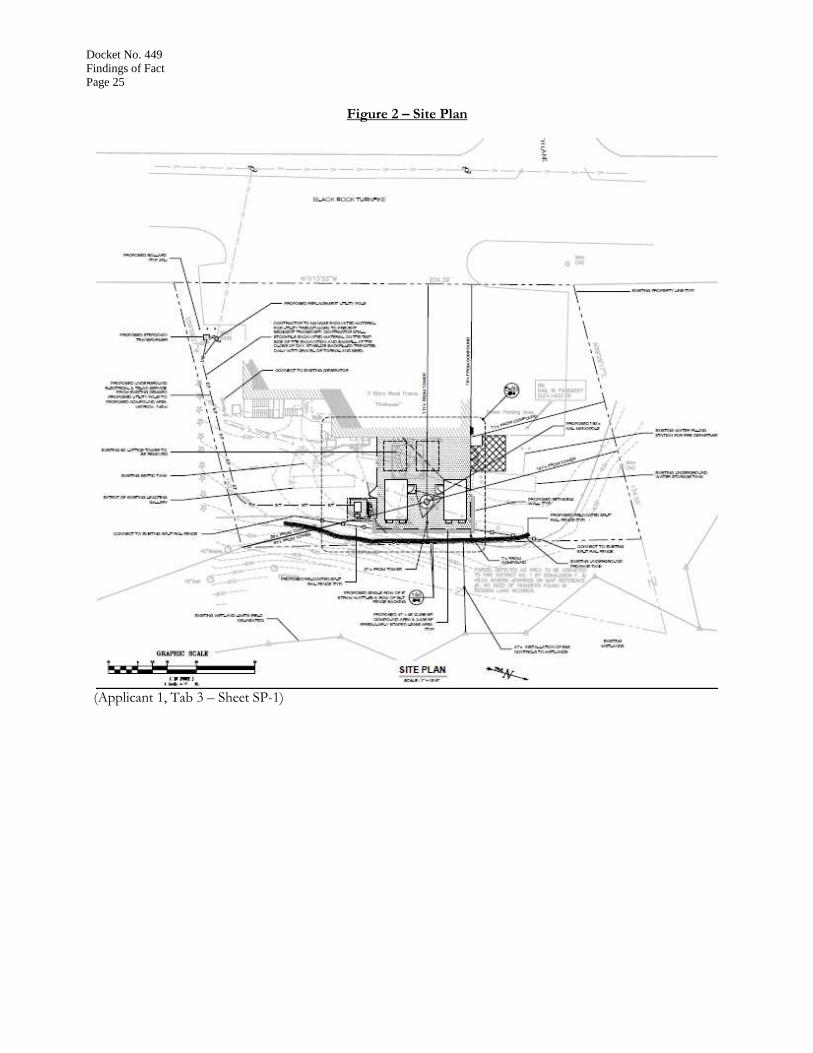
Figure 2 – Site Plan
(Applicant 1, Tab 3 – Sheet SP-1)
Docket No. 449
Findings of Fact
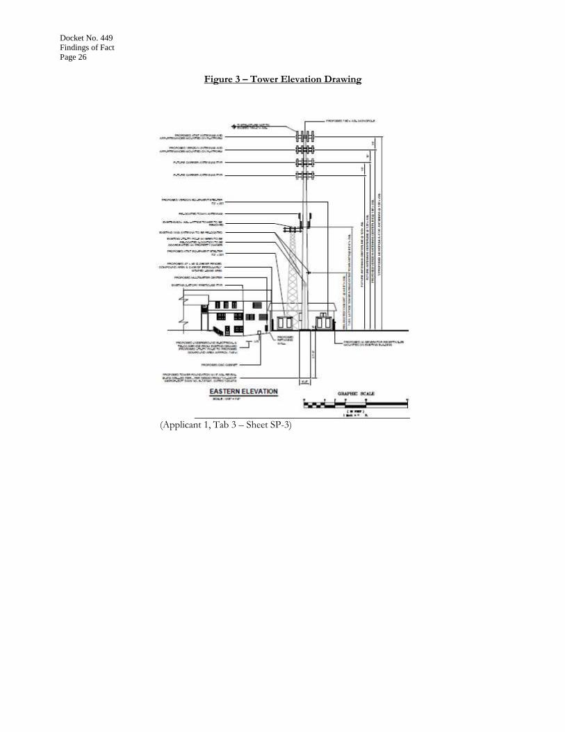
Page 26
Figure 3 – Tower Elevation Drawing
(Applicant 1, Tab 3 – Sheet SP-3)
Docket No. 449
Findings of Fact
Page 27
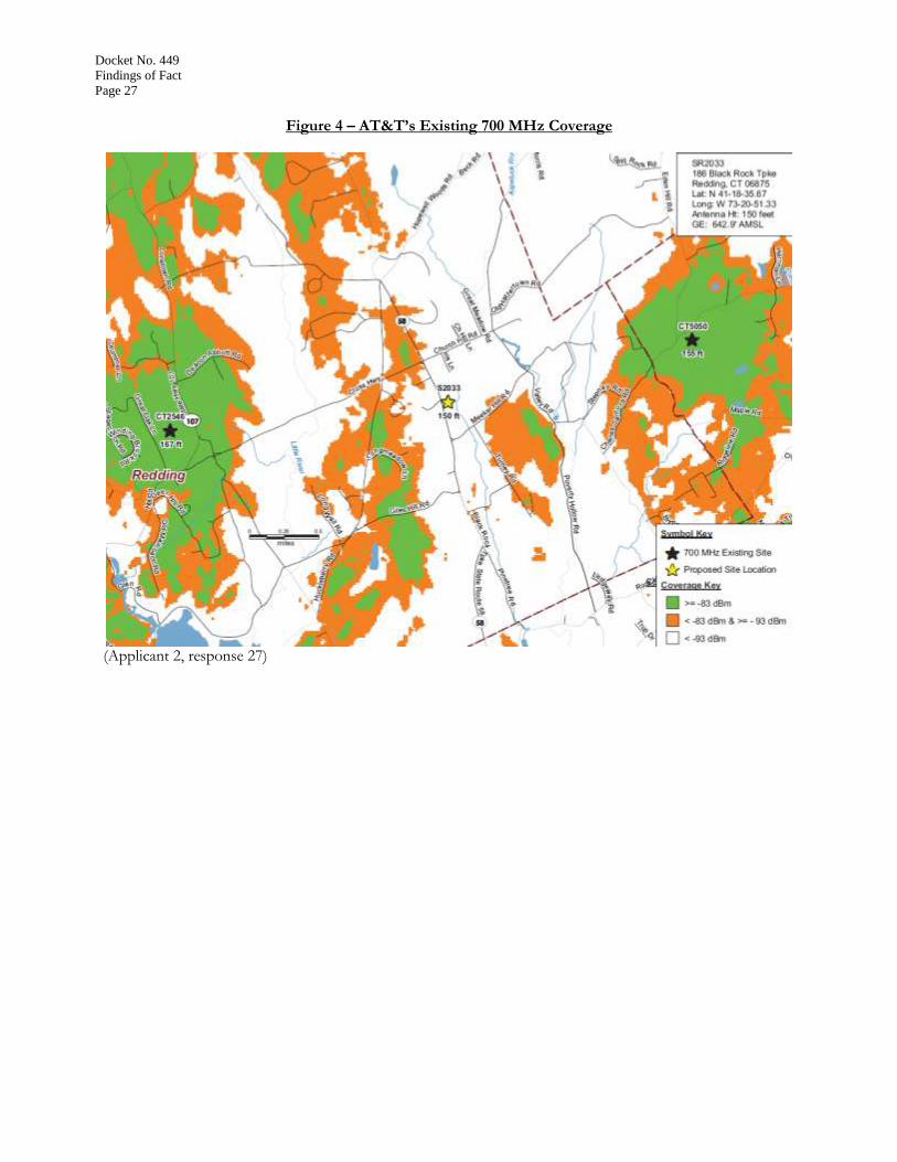
Figure 4 – AT&T’s Existing 700 MHz Coverage
(Applicant 2, response 27)

Docket No. 449
Findings of Fact
Page 28
Figure 5 – AT&T’s Existing and Proposed 700 MHz Coverage at Antenna Centerline Height of 150 feet
(Applicant 2, response 27)

Docket No. 449
Findings of Fact
Page 29
Figure 6 – AT&T’s Existing and Incremental 700 MHz Coverage at Antenna Centerline Height of 120
feet
(Applicant 8, response 56)

Docket No. 449
Findings of Fact
Page 30
Figure 7 – AT&T’s Existing 850 MHz Coverage
(Applicant 2, response 27)

Docket No. 449
Findings of Fact
Page 31
Figure 8 – AT&T’s Existing and Proposed 850 MHz Coverage at Antenna Centerline Height of 150 feet
(Applicant 1, Tab 1 – Radio Frequency Analysis Report, p. 10)

Docket No. 449
Findings of Fact
Page 32
Figure 9 – AT&T’s Existing and Incremental 850 MHz Coverage at Antenna Centerline Height of 120
feet
(Applicant 8, response 56)

Docket No. 449
Findings of Fact
Page 33
Figure 10 – AT&T’s Existing 1900 MHz Coverage
(Applicant 2, response 27)
Docket No. 449
Findings of Fact
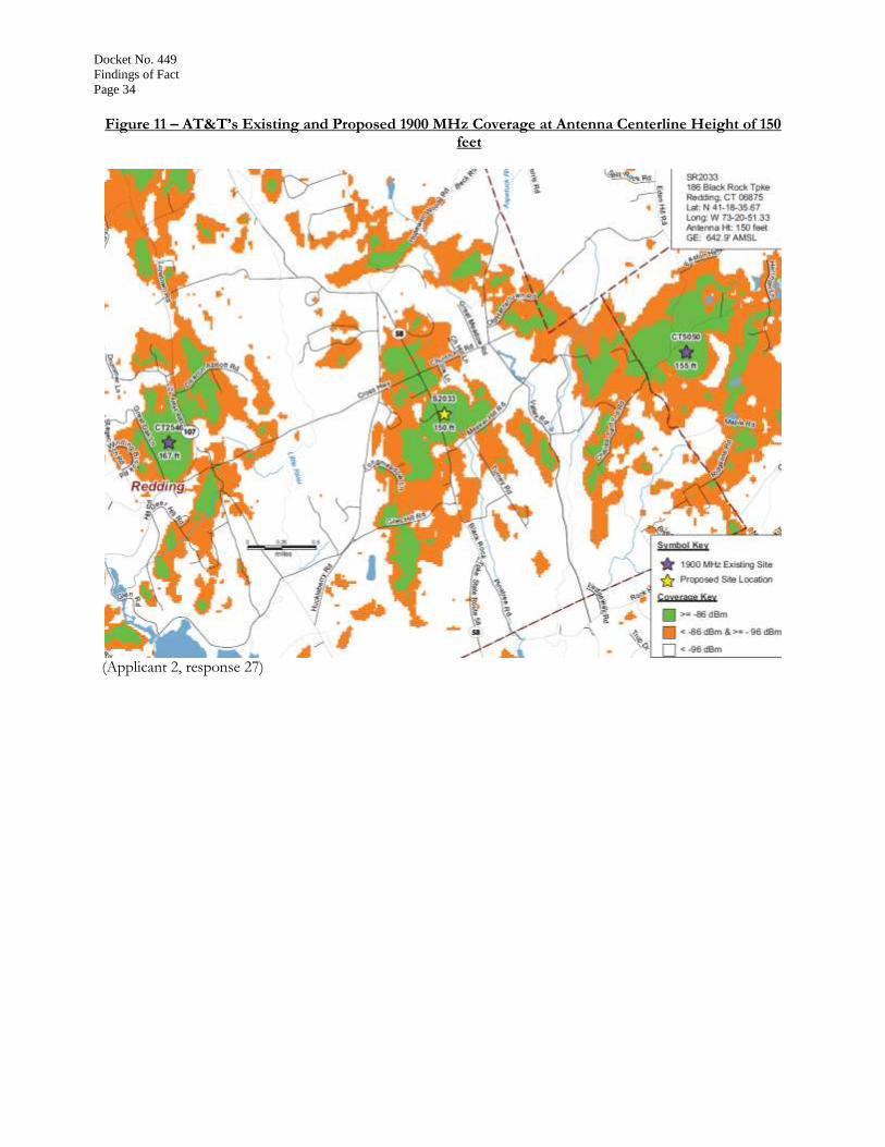
Page 34
Figure 11 – AT&T’s Existing and Proposed 1900 MHz Coverage at Antenna Centerline Height of 150
feet
(Applicant 2, response 27)

Docket No. 449
Findings of Fact
Page 35
Figure 12 – AT&T’s Existing and Incremental 1900 MHz at Antenna Centerline Height of 120 feet
(Applicant 8, response 56)

Docket No. 449
Findings of Fact
Page 36
Figure 13 – Cellco’s Existing 700 MHz Coverage
(Cellco 2, response 24)
Docket No. 449
Findings of Fact
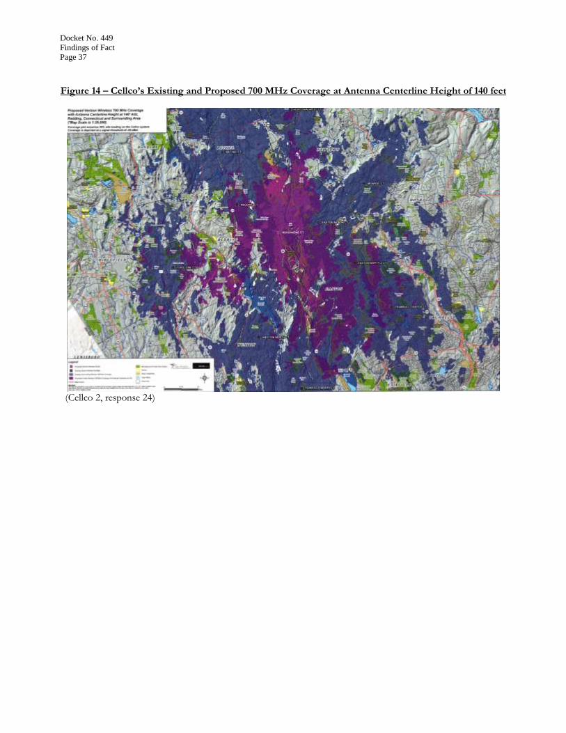
Page 37
Figure 14 – Cellco’s Existing and Proposed 700 MHz Coverage at Antenna Centerline Height of 140 feet
(Cellco 2, response 24)
Docket No. 449
Findings of Fact
Page 38
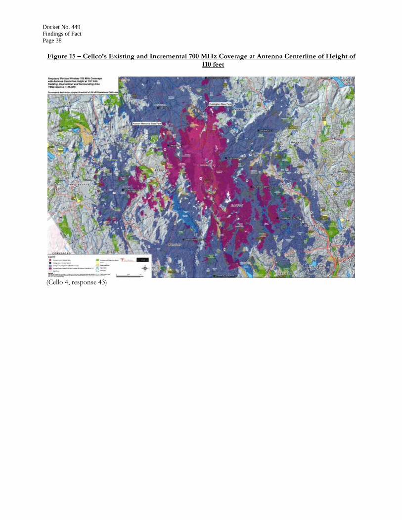
Figure 15 – Cellco’s Existing and Incremental 700 MHz Coverage at Antenna Centerline of Height of
110 feet
(Cello 4, response 43)

Docket No. 449
Findings of Fact
Page 39
Figure 16 – Cellco’s Existing 850 MHz Coverage
(Cellco 2, response 24)

Docket No. 449
Findings of Fact
Page 40
Figure 17 – Cellco’s Existing and Proposed 850 MHz Coverage at Antenna Centerline Height of 140 feet
(Cellco 2, response 24)

Docket No. 449
Findings of Fact
Page 41
Figure 18 – Cellco’s Existing and Incremental 850 MHz Coverage at Antenna Centerline of Height of
110 feet
(Cello 4, response 43)

Docket No. 449
Findings of Fact
Page 42
Figure 19 – Cellco’s Existing 1900 MHz Coverage
(Cellco 2, response 24)

Docket No. 449
Findings of Fact
Page 43
Figure 20 – Cellco’s Existing and Proposed 1900 MHz Coverage at Antenna Centerline Height of 140
feet
(Cellco 2, response 24)

Docket No. 449
Findings of Fact
Page 44
Figure 21 – Cellco’s Existing and Proposed 1900 MHz Coverage at Antenna Centerline of Height of 110
feet
(Cello 4, response 43)

Docket No. 449
Findings of Fact
Page 45
Figure 22 – Cellco’s Existing 2100 MHz Coverage
(Cellco 2, response 24)

Docket No. 449
Findings of Fact
Page 46
Figure 23 – Cellco’s Existing and Proposed 2100 MHz Coverage at Antenna Centerline Height of 140
feet
(Cellco 2, response 24)
Docket No. 449
Findings of Fact
Page 47
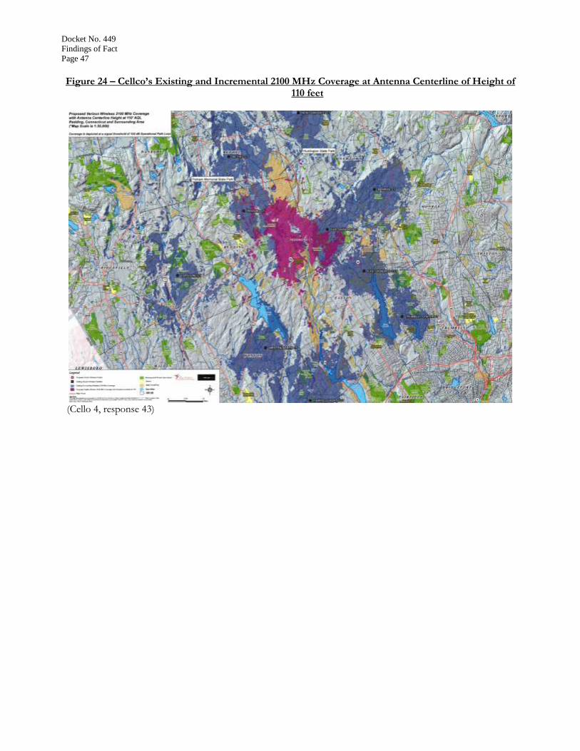
Figure 24 – Cellco’s Existing and Incremental 2100 MHz Coverage at Antenna Centerline of Height of
110 feet
(Cello 4, response 43)

Docket No. 449
Findings of Fact
Page 48
Figure 25 – Visibility Analysis at Proposed Tower Height of 150 feet
(Applicant 1, Tab 5 – Viewshed Map)
Figure 26 – Visibility Analysis at a Tower Height of 120 feet
(Council Administrative Notice Item No. 25 – Docket No. 334 Viewshed Map)

Docket No. 449
Findings of Fact
Page 49
Figure 27 – Photo-simulation
(Applicant 1, Tab 5 – Visibility Report, Photo-simulation No. 1)

Docket No. 449
Findings of Fact
Page 50
Figure 28 – Photo-simulation
(Applicant 1, Tab 5 – Visibility Report, Photo-simulation No. 6)

Docket No. 449
Findings of Fact
Page 51
Figure 29 – Photo-simulation
(Applicant 1, Tab 5 – Visibility Report, Photo-simulation No. 7)