Embed Size (px)
Citation preview
DRAFT
EUROPEAN pr ETS 300 392-4-2
TELECOMMUNICATION July 1999
STANDARD
Source: TETRA Reference: DE/TETRA-03001-04-2
ICS: 33.020
Key words: ISDN, radio, TETRA, V+D
Terrestrial Trunked Radio (TETRA);Voice plus Data (V+D)
Part 4: Gateway basic operation;Sub-part 2: Integrated Services Digital Network (ISDN) gateway
ETSI
European Telecommunications Standards Institute
ETSI Secretariat
Postal address: F-06921 Sophia Antipolis CEDEX - FRANCEOffice address: 650 Route des Lucioles - Sophia Antipolis - Valbonne - FRANCEInternet: [email protected] - http://www.etsi.org
Tel.: +33 4 92 94 42 00 - Fax: +33 4 93 65 47 16
Copyright Notification: No part may be reproduced except as authorized by written permission. The copyright and theforegoing restriction extend to reproduction in all media.
© European Telecommunications Standards Institute 1999. All rights reserved.

Page 2Draft prETS 300 392-4-2: July 1999
Whilst every care has been taken in the preparation and publication of this document, errors in content,typographical or otherwise, may occur. If you have comments concerning its accuracy, please write to"ETSI Standards Making Support Dept." at the address shown on the title page.
Page 3Draft prETS 300 392-4-2: July 1999
Contents
Foreword ..................................................................................................................................................... 11
1 Scope................................................................................................................................................ 13
2 Normative references ....................................................................................................................... 13
3 Definitions, symbols and abbreviations............................................................................................. 153.1 Definitions.......................................................................................................................... 153.2 Abbreviations..................................................................................................................... 16
4 ISDN gateway stage 1 specification.................................................................................................. 174.1 Description......................................................................................................................... 17
4.1.1 General description....................................................................................... 174.1.2 Qualifications on applicability to telecommunication services....................... 17
4.2 Procedures ........................................................................................................................ 174.2.1 Provision/withdrawal ..................................................................................... 174.2.2 Normal procedures ....................................................................................... 17
4.2.2.1 Activation/deactivation/registration/interrogation................. 174.2.2.2 Invocation and operation ..................................................... 17
4.2.2.2.1 Maintenance of the TETRA call............ 184.2.2.2.2 Termination of the TETRA call ............. 18
4.2.3 Exceptional procedures ................................................................................ 184.2.3.1 Activation/deactivation/registration/interrogation................. 184.2.3.2 Invocation and operation ..................................................... 18
4.3 Interaction with TETRA supplementary services............................................................... 184.3.1 Calling Line Identification Presentation (SS-CLIP)........................................ 19
4.3.1.1 Incoming call set-up at ISDN gateway ................................ 194.3.1.2 Outgoing call set-up at ISDN gateway................................. 194.3.1.3 Call maintenance phase...................................................... 19
4.3.2 Connected Line Identification Presentation (SS-COLP) ............................... 194.3.2.1 Incoming call set-up at ISDN gateway ................................ 194.3.2.2 Outgoing call set-up at ISDN gateway................................. 194.3.2.3 Call maintenance phase...................................................... 19
4.3.3 Calling Line Identification Restriction (SS-CLIR) .......................................... 194.3.3.1 Incoming call set-up at ISDN gateway ................................ 194.3.3.2 Outgoing call set-up at ISDN gateway................................. 204.3.3.3 Call maintenance phase...................................................... 20
4.3.4 Connected Line Identification Restriction(SS-COLR) ................................... 204.3.4.1 Incoming call set-up at ISDN gateway ................................ 204.3.4.2 Outgoing call set-up at ISDN gateway................................. 204.3.4.3 Call maintenance phase...................................................... 20
4.3.5 Call Report (SS-CR) ..................................................................................... 204.3.5.1 Incoming call set-up at ISDN gateway ................................ 204.3.5.2 Outgoing call set-up at ISDN gateway................................. 204.3.5.3 Call maintenance phase...................................................... 20
4.3.6 Talking Party Identification (SS-TPI)............................................................. 214.3.6.1 Incoming call set-up at ISDN gateway ................................ 214.3.6.2 Outgoing call set-up at ISDN gateway................................. 214.3.6.3 Call maintenance phase...................................................... 21
4.3.7 Call Forwarding Unconditional (SS-CFU) ..................................................... 214.3.7.1 Incoming call set-up at ISDN gateway ................................ 214.3.7.2 Outgoing call set-up at ISDN gateway................................. 21
4.3.7.2.1 ISDN subscriber number dialled:.......... 214.3.7.2.2 TETRA identity dialled: ......................... 21
4.3.7.3 Call maintenance phase...................................................... 214.3.8 Call Forwarding on Busy (SS-CFB) .............................................................. 21
4.3.8.1 Incoming call set-up at ISDN gateway ................................ 21
Page 4Draft prETS 300 392-4-2: July 1999
4.3.8.2 Outgoing call set-up at ISDN gateway.................................224.3.8.2.1 ISDN subscriber number dialled ...........224.3.8.2.2 TETRA identity dialled ..........................22
4.3.8.3 Call maintenance phase ......................................................224.3.9 Call Forwarding on No Reply (SS-CFNRy) ...................................................22
4.3.9.1 Incoming call set-up at ISDN gateway.................................224.3.9.1.1 Individual calls.......................................224.3.9.1.2 Group calls............................................22
4.3.9.2 Outgoing call set-up at ISDN gateway.................................224.3.9.2.1 ISDN subscriber number dialled ...........224.3.9.2.2 TETRA identity dialled ..........................22
4.3.9.3 Call maintenance phase ......................................................224.3.10 Call Forwarding on Not Reachable (SS-CFNRc) ..........................................23
4.3.10.1 Incoming call set-up at ISDN gateway.................................234.3.10.1.1 Individual calls.......................................234.3.10.1.2 Group calls............................................23
4.3.10.2 Outgoing call set-up at ISDN gateway.................................234.3.10.2.1 ISDN subscriber number dialled ...........234.3.10.2.2 TETRA identity dialled ..........................23
4.3.10.3 Call maintenance phase ......................................................234.3.11 List Search Call (SS-LSC).............................................................................23
4.3.11.1 Incoming call set-up at ISDN gateway.................................234.3.11.2 Outgoing call set-up at ISDN gateway.................................234.3.11.3 Call maintenance phase ......................................................23
4.3.12 Call Authorized by Dispatcher (SS-CAD) ......................................................244.3.12.1 Incoming call set-up at ISDN gateway.................................244.3.12.2 Outgoing call set-up at ISDN gateway.................................244.3.12.3 Call maintenance phase ......................................................24
4.3.13 Short Number Addressing (SS-SNA) ............................................................244.3.13.1 Incoming call set-up at ISDN gateway.................................244.3.13.2 Outgoing call set-up at ISDN gateway.................................244.3.13.3 Call maintenance phase ......................................................24
4.3.14 Area Selection (SS-AS) .................................................................................244.3.14.1 Incoming call set-up at ISDN gateway.................................244.3.14.2 Outgoing call set-up at ISDN gateway.................................254.3.14.3 Call maintenance phase ......................................................25
4.3.15 Access Priority (SS-AP).................................................................................254.3.15.1 Incoming call set-up at ISDN gateway.................................254.3.15.2 Outgoing call set-up at ISDN gateway.................................254.3.15.3 Call maintenance phase ......................................................25
4.3.16 Priority Call (SS-PC)......................................................................................254.3.16.1 Incoming call set-up at ISDN gateway.................................254.3.16.2 Outgoing call set-up at ISDN gateway.................................254.3.16.3 Call maintenance phase ......................................................26
4.3.17 Call Waiting (SS-CW)....................................................................................264.3.17.1 Incoming call set-up at ISDN gateway.................................264.3.17.2 Outgoing call set-up at ISDN gateway.................................264.3.17.3 Call maintenance phase ......................................................26
4.3.18 Call Hold (SS-HOLD) ....................................................................................264.3.18.1 Incoming call set-up at ISDN gateway.................................264.3.18.2 Outgoing call set-up at ISDN gateway.................................264.3.18.3 Call maintenance phase ......................................................26
4.3.19 Call Completion to Busy Subscriber (SS-CCBS) ..........................................264.3.19.1 Incoming call set-up at ISDN gateway.................................264.3.19.2 Outgoing call set-up at ISDN gateway.................................264.3.19.3 Call maintenance phase ......................................................27
4.3.20 Late Entry (SS-LE) ........................................................................................274.3.20.1 Incoming call set-up at ISDN gateway.................................274.3.20.2 Outgoing call set-up at ISDN gateway.................................274.3.20.3 Call maintenance phase ......................................................27
4.3.21 Transfer of Control (SS-TC) ..........................................................................274.3.21.1 Incoming call set-up at ISDN gateway.................................274.3.21.2 Outgoing call set-up at ISDN gateway.................................27
Page 5Draft prETS 300 392-4-2: July 1999
4.3.21.3 Call maintenance phase...................................................... 274.3.22 Pre-emptive Priority Call (SS-PPC)............................................................... 27
4.3.22.1 Incoming call set-up at ISDN gateway ................................ 274.3.22.2 Outgoing call set-up at ISDN gateway................................. 284.3.22.3 Call maintenance phase...................................................... 28
4.3.23 Include Call (SS-IC) ...................................................................................... 284.3.23.1 Incoming call set-up at ISDN gateway ................................ 284.3.23.2 Outgoing call set-up at ISDN gateway................................. 284.3.23.3 Call maintenance phase...................................................... 28
4.3.24 Advice of Charge (SS-AoC) .......................................................................... 284.3.24.1 Incoming call set-up at ISDN gateway ................................ 284.3.24.2 Outgoing call set-up at ISDN gateway................................. 284.3.24.3 Call maintenance phase...................................................... 28
4.3.25 Barring of Outgoing Calls (SS-BOC)............................................................. 284.3.25.1 Incoming call set-up at ISDN gateway ................................ 284.3.25.2 Outgoing call set-up at ISDN gateway................................. 294.3.25.3 Call maintenance phase...................................................... 29
4.3.26 Barring of Incoming Calls (SS-BIC) .............................................................. 294.3.26.1 Incoming call set-up at ISDN gateway ................................ 294.3.26.2 Outgoing call set-up at ISDN gateway................................. 294.3.26.3 Call maintenance phase...................................................... 29
4.3.27 Discreet Listening (SS-DL) ........................................................................... 294.3.27.1 Incoming call set-up at ISDN gateway ................................ 294.3.27.2 Outgoing call set-up at ISDN gateway................................. 294.3.27.3 Call maintenance phase...................................................... 29
4.3.28 Ambience Listening (SS-AL)......................................................................... 304.3.29 Dynamic Group Number Assignment (SS-DGNA) ....................................... 30
4.3.29.1 Incoming call set-up at ISDN gateway ................................ 304.3.29.2 Outgoing call set-up at ISDN gateway................................. 304.3.29.3 Call maintenance phase...................................................... 30
4.3.30 Call Completion on No Reply (SS-CCNR) .................................................... 304.3.30.1 Incoming call set-up at ISDN gateway ................................ 304.3.30.2 Outgoing call set-up at ISDN gateway................................. 304.3.30.3 Call maintenance phase...................................................... 30
4.3.31 Call Retention (SS-CRT)............................................................................... 304.3.31.1 Incoming call set-up at ISDN gateway ................................ 304.3.31.2 Outgoing call set-up at ISDN gateway................................. 314.3.31.3 Call maintenance phase...................................................... 31
4.4 Interactions with ISDN supplementary services ................................................................ 314.4.1 Three-Party (3PTY)....................................................................................... 31
4.4.1.1 Incoming call set-up at ISDN gateway ................................ 314.4.1.2 Outgoing call set-up at ISDN gateway................................. 314.4.1.3 Call maintenance phase...................................................... 31
4.4.2 Advice of Charge (SS-AoC) .......................................................................... 314.4.3 Call Completion to Busy Subscriber (CCBS) ................................................ 32
4.4.3.1 Incoming call set-up at ISDN gateway ................................ 324.4.3.2 Outgoing call set-up at ISDN gateway................................. 324.4.3.3 Call maintenance phase...................................................... 32
4.4.4 Call Completion on No Reply (CCNR) .......................................................... 324.4.4.1 Incoming call set-up at ISDN gateway ................................ 324.4.4.2 Outgoing call set-up at ISDN gateway................................. 324.4.4.3 Call maintenance phase...................................................... 32
4.4.5 Call Deflection (CD) ...................................................................................... 324.4.5.1 Incoming call set-up at ISDN gateway ................................ 324.4.5.2 Outgoing call set-up at ISDN gateway................................. 324.4.5.3 Call maintenance phase...................................................... 32
4.4.6 Call Forwarding Busy (CFB) ......................................................................... 334.4.6.1 Incoming call set-up at ISDN gateway ................................ 334.4.6.2 Outgoing call set-up at ISDN gateway................................. 334.4.6.3 Call maintenance phase...................................................... 33
4.4.7 Call Forwarding on No Reply (CFNR)........................................................... 334.4.7.1 Incoming call set-up at ISDN gateway ................................ 334.4.7.2 Outgoing call set-up at ISDN gateway................................. 33
Page 6Draft prETS 300 392-4-2: July 1999
4.4.7.3 Call maintenance phase ......................................................334.4.8 Call Forwarding Unconditional (CFU)............................................................33
4.4.8.1 Incoming call set-up at ISDN gateway.................................334.4.8.2 Outgoing call set-up at ISDN gateway.................................334.4.8.3 Call maintenance phase ......................................................34
4.4.9 Calling Line Identification Presentation (CLIP) ..............................................344.4.9.1 Incoming call set-up at ISDN gateway.................................344.4.9.2 Outgoing call set-up at ISDN gateway.................................344.4.9.3 Call maintenance phase ......................................................34
4.4.10 Calling Line Identification Restriction (CLIR).................................................344.4.10.1 Incoming call set-up at ISDN gateway.................................344.4.10.2 Outgoing call set-up at ISDN gateway.................................344.4.10.3 Call maintenance phase ......................................................35
4.4.11 Connected Line Identification Presentation (COLP)......................................354.4.11.1 Incoming call set-up at ISDN gateway.................................354.4.11.2 Outgoing call set-up at ISDN gateway.................................354.4.11.3 Call maintenance phase ......................................................35
4.4.12 Connected Line Identification Restriction (COLR).........................................354.4.12.1 Incoming call set-up at ISDN gateway.................................354.4.12.2 Outgoing call set-up at ISDN gateway.................................354.4.12.3 Call maintenance phase ......................................................36
4.4.13 Conference call, add on (CONF)...................................................................364.4.13.1 Incoming call set-up at ISDN gateway.................................364.4.13.2 Outgoing call set-up at ISDN gateway.................................364.4.13.3 Call maintenance phase ......................................................36
4.4.14 Closed User Group (CUG) ............................................................................364.4.15 Call Waiting (CW)..........................................................................................36
4.4.15.1 Incoming call set-up at ISDN gateway.................................364.4.15.2 Outgoing call set-up at ISDN gateway.................................364.4.15.3 Call maintenance phase ......................................................37
4.4.16 Direct Dial In (DDI) ........................................................................................374.4.16.1 Incoming call set-up at ISDN gateway.................................374.4.16.2 Outgoing call set-up at ISDN gateway.................................374.4.16.3 Call maintenance phase ......................................................37
4.4.17 Explicit Call Transfer (ECT)...........................................................................374.4.18 Freephone (FPH) ..........................................................................................37
4.4.18.1 Incoming call set-up at ISDN gateway.................................374.4.18.2 Outgoing call set-up at ISDN gateway.................................374.4.18.3 Call maintenance phase ......................................................37
4.4.19 Call Hold (HOLD) ..........................................................................................384.4.19.1 Incoming call set-up at ISDN gateway.................................384.4.19.2 Outgoing call set-up at ISDN gateway.................................384.4.19.3 Call maintenance phase ......................................................38
4.4.20 Malicious Call Identification (MCID) ..............................................................384.4.21 Multiple Subscriber Number (MSN)...............................................................38
4.4.21.1 Incoming call set-up at ISDN gateway.................................384.4.21.2 Outgoing call set-up at ISDN gateway.................................384.4.21.3 Call maintenance phase ......................................................38
4.4.22 Message Waiting Indication (MWI) ...............................................................384.4.23 Outgoing Call Barring (OCB).........................................................................39
4.4.23.1 Incoming call set-up at ISDN gateway.................................394.4.23.2 Outgoing call set-up at ISDN gateway.................................394.4.23.3 Call maintenance phase ......................................................39
4.4.24 Subaddressing (SUB)....................................................................................394.4.24.1 Incoming call set-up at ISDN gateway.................................394.4.24.2 Outgoing call set-up at ISDN gateway.................................394.4.24.3 Call maintenance phase ......................................................39
4.4.25 Terminal Portability (TP)................................................................................394.4.25.1 Incoming call set-up at ISDN gateway.................................394.4.25.2 Outgoing call set-up at ISDN gateway.................................394.4.25.3 Call maintenance phase ......................................................39
4.4.26 User-to-User signalling (UUS).......................................................................404.4.26.1 Incoming call set-up at ISDN gateway.................................40
Page 7Draft prETS 300 392-4-2: July 1999
4.4.26.2 Outgoing call set-up at ISDN gateway................................. 404.4.26.3 Call maintenance phase...................................................... 40
4.5 Interworking considerations............................................................................................... 404.6 ISDN gateway service description..................................................................................... 40
4.6.1 ISDN gateway service................................................................................... 404.6.1.1 ISDN gateway primitives exchanged through the
ISDNCC-SAP ...................................................................... 404.6.1.2 Service primitives at the ISDNCC-SAP............................... 414.6.1.3 Service primitive description................................................ 41
4.6.1.3.1 ISDNCC-ALERTING primitive .............. 424.6.1.3.2 ISDNCC-COMPLETE primitive ............ 424.6.1.3.3 ISDNCC-RELEASE primitive................ 424.6.1.3.4 ISDNCC-SETUP primitive .................... 424.6.1.3.5 ISDNCC-TX primitive ........................... 43
4.6.1.4 Parameter descriptions ....................................................... 444.6.1.5 Overall SDL ......................................................................... 454.6.1.6 Static description of ISDN gateway attributes ..................... 49
5 TETRA gateway stage 2 specification .............................................................................................. 505.1 Functional model ............................................................................................................... 50
5.1.1 Functional model description ........................................................................ 505.1.2 Description of functional entities ................................................................... 51
5.1.2.1 SwMI call control application functional entity, FE1............. 515.1.2.2 ISDN interface functional entity, FE2 .................................. 515.1.2.3 ISDN network, FE3.............................................................. 51
5.2 Information flow ................................................................................................................. 515.2.1 Information flow diagrams............................................................................. 51
5.2.1.1 Successful call set-up to an ISDN subscriber ..................... 525.2.1.2 Successful call set-up from an ISDN subscriber over the
ISDN gateway...................................................................... 545.2.1.3 Call set-up request from an ISDN subscriber queued......... 575.2.1.4 Unsuccessful call set-up to an ISDN subscriber ................. 585.2.1.5 Unsuccessful call set-up from an ISDN subscriber............. 595.2.1.6 Unsuccessful call set-up, B-channel not accepted.............. 625.2.1.7 Call maintenance procedures - Transmission control
towards an ISDN subscriber................................................ 635.2.1.8 Call maintenance procedures - Interrupt of transmitting
ISDN subscriber .................................................................. 645.2.1.9 Call maintenance procedures - Withdrawal of
transmission in the gateway SwMI ...................................... 645.2.1.10 Call disconnection procedures - Request to disconnect
from a TETRA user or TETRA SwMI .................................. 655.2.1.11 Call disconnection procedures - Request to disconnect
from the ISDN network........................................................ 665.3 Functional Entity Actions (FEAs) ....................................................................................... 66
5.3.1 Functional entity actions of FE2.................................................................... 66
6 ISDN gateway stage 3 specification.................................................................................................. 686.1 Protocol structure and protocol stack ................................................................................ 686.2 TETRA gateway coding requirements............................................................................... 68
6.2.1 Non end-to-end ISDN calls ........................................................................... 696.2.1.1 Alert tone ............................................................................. 696.2.1.2 Busy tone............................................................................. 696.2.1.3 Disconnect tone................................................................... 696.2.1.4 Invalid number tone............................................................. 69
6.2.2 Two stage dialling ......................................................................................... 696.2.2.1 Dialling Tone ....................................................................... 696.2.2.2 Dialling................................................................................. 696.2.2.3 Call set-up tones sent in-band............................................. 69
6.2.3 Call set-up queuing ....................................................................................... 706.2.3.1 TETRA queuing tone............................ 70
6.2.4 Transmission signalling................................................................................. 706.2.4.1 User-to-User Signalling ....................................................... 70
Page 8Draft prETS 300 392-4-2: July 1999
6.2.4.2 DTMF signalling...................................................................706.2.4.3 Guidance tones....................................................................70
6.2.4.3.1 TX-ceased tone ....................................706.2.4.3.2 TX-granted tone....................................706.2.4.3.3 TX-interrupt tone...................................70
6.2.5 DTMF signalling during ACTIVE state...........................................................716.2.5.1 From ISDN network .............................................................716.2.5.2 From TETRA network..........................................................71
6.3 TETRA gateway state definitions.......................................................................................716.4 TETRA gateway signalling procedures..............................................................................71
6.4.1 Call set-up procedures ..................................................................................716.4.1.1 Incoming calls ......................................................................71
6.4.1.1.1 Two stage dialling .................................726.4.1.1.2 Acknowledged group calls ....................726.4.1.1.3 Broadcast calls......................................726.4.1.1.4 Call priority ............................................72
6.4.1.2 Outgoing calls ......................................................................726.4.1.2.1 Two stage dialling .................................726.4.1.2.2 Acknowledged group calls ....................736.4.1.2.3 Broadcast calls......................................73
6.4.1.3 Colliding calls .......................................................................736.4.1.4 Unsuccessful call set-up......................................................73
6.4.2 Call maintenance procedures........................................................................736.4.2.1 Transmission request ..........................................................74
6.4.2.1.1 Voice activity detection..........................746.4.2.1.2 User-to-user signalling..........................746.4.2.1.3 DTMF signalling ....................................75
6.4.2.2 Transmission request response ..........................................756.4.2.2.1 Voice activity detection..........................756.4.2.2.2 User-to-user signalling..........................756.4.2.2.3 DTMF signalling ....................................75
6.4.2.3 End of transmission .............................................................766.4.2.3.1 Voice activity detection..........................766.4.2.3.2 User-to-user signalling..........................766.4.2.3.3 DTMF signalling ....................................76
6.4.2.4 Interruption of transmission .................................................766.4.2.4.1 Voice activity detection..........................766.4.2.4.2 User-to-user signalling..........................766.4.2.4.3 DTMF signalling ....................................76
6.4.3 Call disconnection procedures ......................................................................776.4.3.1 Disconnect initiated by TETRA user or TETRA SwMI.........776.4.3.2 Disconnection initiated by ISDN subscriber.........................776.4.3.3 Colliding disconnection ........................................................77
6.5 Protocol interaction between TETRA gateway and TETRA supplementary services........776.6 Protocol interaction between TETRA gateway and ISDN supplementary services ...........776.7 TETRA gateway parameter values (timers).......................................................................77
Annex A (normative): Specification and description Language (SDL) representation of procedures ...78
A.1 SDL representation of ISDN interface entity FE2..............................................................................78
Annex B (normative): TETRA group call set-up with external ISDN group members...........................85
B.1 User-to-user signalling service 3 .......................................................................................................85B.1.1 Functional Entity Actions (FEAs) .......................................................................................88
B.1.1.1 Functional entity actions of FE2 ....................................................................88
Annex C (informative): Static description of the TETRA ISDN gateway bearer service, usingattributes.............................................................................................................89
C.1 Information transfer attributes ...........................................................................................................89
C.2 Access attributes ...............................................................................................................................89

Page 9Draft prETS 300 392-4-2: July 1999
Annex D (informative): Mapping of TETRA disconnection causes to ISDN disconnection causes........ 90
D.1 Mapping of TETRA disconnect causes............................................................................................. 90
Annex E (informative): TETRA supplementary services ........................................................................ 93
E.1 TETRA supplementary services - SCCF .......................................................................................... 93
Annex F (informative): Bibliography........................................................................................................ 94
History ......................................................................................................................................................... 95

Page 10Draft prETS 300 392-4-2: July 1999
Blank page
Page 11Draft prETS 300 392-4-2: July 1999
Foreword
This European Telecommunication Standard (ETS) has been produced by the Terrestrial Trunked Radio(TETRA) Project of the European Telecommunications Standards Institute (ETSI), and is now submittedfor the Public Enquiry phase of the ETSI standards approval procedure.
This ETS consists of 14 parts as follows:
Part 1: "General network design";
Part 2: "Air Interface (AI)";
Part 3: "Interworking at the Inter-System Interface (ISI)";
Part 4: "Gateways basic operation";
Part 5: "Peripheral Equipment Interface (PEI)";
Part 6: "Line connected Station (LS)";
Part 7: "Security";
Part 9: "General requirements for supplementary services";
Part 10: "Supplementary services stage 1";
Part 11: "Supplementary services stage 2";
Part 12: "Supplementary services stage 3";
Part 13: "SDL model of the Air Interface (AI)";
Part 14: "Protocol Implementation Conformance Statement (PICS) proforma specification".
Proposed transposition dates
Date of latest announcement of this ETS (doa): 3 months after ETSI publication
Date of latest publication of new National Standardor endorsement of this ETS (dop/e): 6 months after doa
Date of withdrawal of any conflicting National Standard (dow): 6 months after doa

Page 12Draft prETS 300 392-4-2: July 1999
Blank page
Page 13Draft prETS 300 392-4-2: July 1999
1 Scope
This ETS defines the Terrestrial Trunked Radio (TETRA) system supporting Voice plus Data (V+D). Inaccordance with ITU-T Recommendations I.130 [28], the stage one, stage two and stage three of thethree level structure is used to specify the TETRA gateway to Public Integrated Services Digital Network(ISDN):
- Stage 1, is an overall service description, from the service subscriber’s and user’s standpoint;
- Stage 2, identifies the functional capabilities and information flows needed to support the servicesdescribed in stage 1, and
NOTE 1: The information flows in stage 2 have been drawn as Message Sequence Charts(MSCs).
- Stage 3, defines the signalling system protocols and switching functions needed to implement theservices described in stage 1.
Specifically this standard details the stage 1 aspects (overall service description) of the TETRA gatewayas seen from the TETRA Switching and Maintenance Infrastructure point of view at the T reference pointor coincident S and T reference points for the ISDN subscriber.
NOTE 2: This standard is applicable at the T and S references. It should however be noted, thatno standards exist for the S reference point.
It details the stage 2 aspects (functional partitioning) of the TETRA gateway which includes theidentification of the functional entities and the flows between them and finally it details the stage 3signalling protocols for the TETRA gateway services, i.e. the protocol at the relevant reference pointsbetween the functional entities defined in stage 2. The described network layer services and protocolsapply for the Switching and Management Infrastructure (SwMI), for the TETRA gateway and to the keypadprotocol for the ISDN subscriber using TETRA services.
A basic call is initiated at the TETRA gateway when, a SwMI detects an incoming call from an ISDNsubscriber to a TETRA user or an outgoing call is made from a TETRA user to an ISDN subscriber. TheTETRA gateway ensures that basic signalling required in the operation of the TETRA call and the ISDNcall is maintained across the gateway.
The TETRA gateway and the TETRA system are seen by the external network as if it were a subscriber(users side) of the external network. For incoming calls from ISDN three methods of addressing a TETRAuser are applicable, Subaddressing (SUB), Direct Dial In (DDI) and two stage dialing. Other means ofincoming calls using other than ISDN subscriber lines, between the TETRA system and the externalnetwork exchange are outside the scope of this ETS.
End to end encryption is outside the scope of this ETS.
This ETS describes the TETRA gateway function, which provides an ISDN interface to the SwMI. Primaryand basic rate is supported. However, multiple gateways on the same basic rate bus are not supported.
Circuit mode data calls are outside the scope of this ETS.
2 Normative references
This European Telecommunications Standard (ETS) incorporates by dated and undated reference,provisions from other publications. These normative references are cited at the appropriate places in thetext and the publications are listed hereafter. For dated references, subsequent amendments to orrevisions of any of these publications apply to this European Telecommunications Standard only whenincorporated in it by amendment or revision. For undated references the latest edition of the publicationreferred to apply.
[1] EN 300 058-1: "Integrated Services Digital Network (ISDN); Call Waiting (CW)supplementary service; Digital Subscriber Signalling System No. one (DSS1)protocol; Part 1: Protocol specification".
Page 14Draft prETS 300 392-4-2: July 1999
[2] EN 301 065-1: "Integrated Services Digital Network (ISDN); Completion of Callson No Reply (CCNR) supplementary service; Digital Subscriber SignallingSystem No. one (DSS1) protocol; Part 1: Protocol specification".
[3] EN 300 092-1: "Integrated Services Digital Network (ISDN); Calling LineIdentification Presentation (CLIP) supplementary service; Digital SubscriberSignalling System No. one (DSS1) protocol; Part 1: Protocol specification".
[4] EN 300 097-1: "Integrated Services Digital Network (ISDN); Connected LineIdentification Presentation (COLP) supplementary service; Digital SubscriberSignalling System No. one (DSS1) protocol; Part 1: Protocol specification".
[5] EN 300 141-1: "Integrated Services Digital Network (ISDN); Call hold (HOLD)supplementary service; Digital Subscriber Signalling System No. one (DSS1)protocol; Part 1: Protocol specification".
[6] EN 300 207-1: "Integrated Services Digital Network (ISDN); Diversionsupplementary services; Digital Subscriber Signalling System No. one (DSS1)protocol; Part 1: Protocol specification".
[7] EN 300 286-1: "Integrated Services Digital Network (ISDN); User-to-UserSignalling (UUS) supplementary service; Digital Subscriber Signalling SystemNo. one (DSS1) protocol; Part 1: Protocol specification".
[8] EN 300 359-1: "Integrated Services Digital Network (ISDN); Completion of Callsto Busy Subscriber (CCBS) supplementary service; Digital Subscriber SignallingSystem No. one (DSS1) protocol; Part 1: Protocol specification".
[9] EN 300 403-1: "Integrated Services Digital Network (ISDN); Digital SubscriberSignalling System No. one (DSS1) protocol; Signalling network layer for circuit-mode basic call control; Part 1: Protocol specification [ITU-T RecommendationQ.931 (1993), modified]".
[10] ETS 300 085: "Integrated Services Digital Network (ISDN); 3,1 kHz telephonyteleservice; Attachment requirements for handset terminals (CandidateNET 33)".
[11] ETS 300 392-1: "Terrestrial Trunked Radio (TETRA); Voice plus Data (V+D);Part 1: General network design".
[12] ETS 300 392-2: "Terrestrial Trunked Radio (TETRA); Voice plus Data (V+D);Part 2: Air Interface (AI)".
[13] ETS 300 392-3: "Terrestrial Trunked Radio (TETRA); Voice plus Data (V+D);Part 3: Interworking at the Inter-System Interface (ISI); Sub-part 1: Generaldesign".
[14] ETS 300 392-4-1: "Terrestrial Trunked Radio (TETRA); Voice plus Data (V+D);Part 4: Gateways basic operation; Sub-part 1: Public Switched TelephoneNetwork (PSTN)".
[15] ETS 300 392-9: "Terrestrial Trunked Radio (TETRA); Voice plus Data (V+D);Part 9: General requirements for supplementary services".
[16] ETS 300 392-12-3: "Terrestrial Trunked Radio (TETRA); Voice plus Data (V+D);Part 12: Supplementary services stage 3; Sub-part 3: Talking Party Identification(TPI)".
[17] ETS 300 392-12-4: "Terrestrial Trunked Radio (TETRA); Voice plus Data (V+D);Part 12: Supplementary services stage 3; Sub-part 4: Call Diversion (CD)".
[18] ETS 300 392-12-8: "Terrestrial Trunked Radio (TETRA); Voice plus Data (V+D);Part 12: Supplementary services stage 3; Sub-part 8: Area Selection (AS)".
Page 15Draft prETS 300 392-4-2: July 1999
[19] ETS 300 392-12-10: "Terrestrial Trunked Radio (TETRA); Voice plus Data(V+D); Part 12: Supplementary services stage 3; Sub-part 10: Priority Call (PC)".
[20] ETS 300 392-12-13: "Terrestrial Trunked Radio (TETRA); Voice plus Data(V+D); Part 12: Supplementary services stage 3; Sub-part 13: Call Completionto Busy Subscriber (CCBS)".
[21] ETS 300 392-12-16: "Terrestrial Trunked Radio (TETRA); Voice plus Data(V+D); Part 12: Supplementary services stage 3; Sub-part 16: Pre-emptivePriority Call (PPC)".
[22] ETS 300 392-12-23: "Terrestrial Trunked Radio (TETRA); Voice plus Data(V+D); Part 12: Supplementary services stage 3; Sub-part 23: Call Completionon No Reply (CCNR)".
[23] ETS 300 738: "Human Factors (HF); Minimum Man-Machine Interface (MMI) topublic network based supplementary services".
[24] ETR 300-5: "Terrestrial Trunked Radio (TETRA); Voice plus Data (V+D);Designers' guide; Part 5: Guidance on Numbering and addressing".
[25] I-ETS 300 245-1: "Integrated Services Digital Network (ISDN); Technicalcharacteristics of telephony terminals; Part 1: General".
[26] ITU-T Recommendation G.711 (1988): "Pulse code modulation (PCM) of voicefrequencies".
[27] ITU-T Recommendation I.112 (1993): "Vocabulary of terms for ISDNs".
[28] ITU-T Recommendation I.130 (1988): "Method for the characterization oftelecommunication services supported by an ISDN and network capabilities ofan ISDN".
[29] ITU-T Recommendation I.140 (1993): "Attribute technique for thecharacterization of telecommunication services supported by an ISDN andnetwork capabilities of an ISDN".
[30] ITU-T Recommendation I.210 (1993): "Principles of telecommunication servicessupported by an ISDN and the means to describe them".
[31] ITU-T Recommendation Z.100 (1993): "CCITT Specification and descriptionlanguage (SDL)".
3 Definitions, symbols and abbreviations
3.1 Definitions
For the purposes of this ETS the following definitions apply:
B-channel: 64 kbit/s channel accompanied by timing intended to carry a wide variety of user informationstreams, i.e. voice, image or data transmission. A B-channel does not carry signalling information forcircuit switching by the ISDN.
D-channel: channel primarily intended to carry signalling information for circuit switching by the ISDN, i.e.call establishment, call monitoring, call termination and enhanced telephone feature information. Out-ofband signalling.
DDI number: ISDN number or part of an ISDN number which is delivered to the TETRA gateway. It canbe the subscriber, national or international number or a partial number. The DDI number is defined to beat least that part of the ISDN number which is significant to the TETRA network.
Page 16Draft prETS 300 392-4-2: July 1999
en bloc receiving: procedure, used in call establishment of an incoming call, to enable the ISDN networkto send called party number digits to the TETRA network in a single message.
in-band signalling: main traffic bearer is used for signalling, data and telemetry information, i.e. B-channel. A signalling method in which signals are sent over the same transmission or circuit channel asthe user’s communication, in the same frequency band as that provided for the user.
incoming call: call from the ISDN to the TETRA network.
Integrated Services Digital Network (ISDN): see ITU-T Recommendation I.112 [27], definition 308.
originating SwMI: SwMI from where the call originates, i.e. where the initial call set-up is detected.
outgoing call: call from a TETRA network to the ISDN.
overlap receiving: procedure, used in call establishment of an incoming call, to enable the ISDN networkto send called party number digits to the TETRA network in successive messages, as and when they aremade available from the ISDN network.
participating SwMI: SwMI only participates in a group call without controlling it and will always be the endpoint of the call.
S reference: conceptual point at the conjunction of the TE1 (terminal equipment type 1) and NT2(network termination type 2) functional groups.
S/T reference: conceptual point at the conjunction of the TE1 and NT1 functional group when the NT2functional group is null.
T reference: conceptual point at the conjunction of the NT1 and NT2 functional groups.
3.2 Abbreviations
For the purposes of this ETS the following abbreviations apply:
3PTY Three-PartyCC Call Control (PISN functional entity)CD Call DeflectionCONF Conference call, add onCUG Closed User GroupCW Call WaitingDDI Direct Dial InDSS1 Digital Subscriber Signalling System Number 1ECT Explicit Call TransferFE Functional EntityFPH FreephoneGTSI Group TETRA Subscriber IdentityIA5 International Alphabet No.5ISDN Integrated Services Digital NetworkITSI Individual TETRA Subscriber IdentityMCID Malicious Call IdentificationMSN Multiple Subscriber NumberMWI Message Waiting IndicationOCB Outgoing Call BarringPINX Private Integrated Services Network ExchangePISN Private Integrated Services NetworkSDL Specification and Description LanguageSUB SubaddressingSwMI Switching and Management InfrastructureTP Terminal PortabilityUUS User-to-User signalling
Page 17Draft prETS 300 392-4-2: July 1999
4 ISDN gateway stage 1 specification
4.1 Description
4.1.1 General description
The ISDN gateway enables calls to be set-up from an ISDN subscriber to a TETRA user and a TETRAuser to an ISDN subscriber. Additionally, for the duration of the call, the ISDN gateway allows ISDNsignalling information to be passed from the external network to the TETRA Switching and ManagementInfrastructure (SwMI) in accordance with the TETRA Call Control (CC) procedures as defined inETS 300 392-2 [12] and TETRA signalling information to be passed from the TETRA SwMI to the externalnetwork in accordance with the ISDN DSS1 Call Control (CC) procedures as defined in EN 300 403-1 [9].
The principles defined in this ETS can be used for interfacing with other networks such as private digitalnetworks, e.g. Private Integrated Services Network Exchange (PINX).
4.1.2 Qualifications on applicability to telecommunication services
The ISDN gateway shall be applicable to clear mode point-to-point and point-to-multipoint circuit modeteleservices used for speech as defined in ETS 300 392-1 [11]. End to end encryption could be supportedbetween a TETRA user and the ISDN gateway, but all provisions are outside the scope of this ETS.
4.2 Procedures
4.2.1 Provision/withdrawal
The ISDN gateway service shall be provided by prior arrangement with the service provider or they maybe generally available.
This service may be withdrawn by the service provider at any time without a prior indication.
4.2.2 Normal procedures
4.2.2.1 Activation/deactivation/registration/interrogation
The ISDN gateway shall be permanently activated upon provision.
Registration and interrogation are not applicable.
4.2.2.2 Invocation and operation
The ISDN gateway shall be invoked either when a call request (incoming call) is received by the gatewayfrom the ISDN network or when a call request has been received to an ISDN subscriber (outgoing call) bythe SwMI.
NOTE: See ETR 300-5 [24] for TETRA dialling and addressing methods.
In the outgoing call case the ISDN gateway shall route the call to the ISDN network using the informationfound in the external subscriber number information elements. The ISDN gateway shall dial the externalnetwork number using appropriate signalling mechanisms defined for that network (see EN 300 403-1 [9]or relevant national requirements not covered by these standards).
In the incoming call case the ISDN gateway shall forward the called TETRA user identity to the SwMI CCentity for the call set-up completion. The called TETRA user shall be addressed either by the ISDN DirectDial In (DDI) supplementary service, by the ISDN Subaddressing (SUB) supplementary service or byusing two stage dialing mechanisms. DDI allows the external subscriber to directly dial a TETRA user orgroup of users, while subaddressing allows the called TETRA user or group of users to be identified by thesubaddress information element in the ISDN SETUP message. Two stage dialing shall be applicablewhen separate ISDN numbers are not required for each individual TETRA user or group and when theISDN supplementary service SUB is not supported by the calling ISDN subscriber.
Page 18Draft prETS 300 392-4-2: July 1999
The ISDN gateway shall remain operational for the duration of the call. The ISDN gateway shall send andreceive TETRA signalling messages as appropriate under direction from the SwMI.
4.2.2.2.1 Maintenance of the TETRA call
An ISDN gateway supporting semi-duplex calls may inform the ISDN subscriber about the state of the calland may either receive explicit request to transmit and cease of transmission from the external networkuser or a voice activity detection mechanism for requests to transmit may be used. The exactmechanisms for voice detection, and its algorithms and how the result is used for the request to transmitare outside the scope of this ETS.
4.2.2.2.2 Termination of the TETRA call
All disconnection request received from the ISDN network shall be forwarded to the controlling or otherend call control application for the call.
All disconnection request received from the controlling or other end call control application shall beforwarded to the ISDN network.
4.2.3 Exceptional procedures
4.2.3.1 Activation/deactivation/registration/interrogation
Not applicable.
4.2.3.2 Invocation and operation
The ISDN gateway may reject an incoming call request with an appropriate failure indication, e.g. for anyof the following reasons:
- no destination number provided;- B channel unacceptable, unavailable or invalid;- bearer capability not valid;- service or option not available;- the called user address is incorrect;- invalid call reference;- invalid message.
See also EN 300 403-1 [9].
The ISDN gateway may reject an outgoing call request with an appropriate failure indication for any of thefollowing reasons:
- no destination number provided;- bearer capability not valid;- service or option not available;- the called user address is incorrect.
In addition, normal ISDN rejection and all restrictions and exceptional procedures for TETRA basic callestablishment shall apply.
4.3 Interaction with TETRA supplementary services
Interactions with TETRA supplementary services for which TETRA Standards or TETRA draft standardswere available at the time of publication of this Standard are specified below. The following interactionsare defined for each TETRA supplementary service:
- incoming call set-up at ISDN gateway;- outgoing call set-up at ISDN gateway;- call maintenance phase.
Page 19Draft prETS 300 392-4-2: July 1999
This subclause defines how and when a TETRA supplementary service will interact with the ISDNgateway and ISDN network when this service has been invoked for a TETRA user.
4.3.1 Calling Line Identification Presentation (SS-CLIP)
4.3.1.1 Incoming call set-up at ISDN gateway
No interaction.
The calling party number is part of the basic call set-up signalling where available. Therefore, no furtherinformation is required from the ISDN network.
NOTE: Calling party subaddressing is not covered by this ETS.
4.3.1.2 Outgoing call set-up at ISDN gateway
Not applicable.
TETRA SS-CLIP is only invoked at a TETRA called user upon reception of an incoming set-up request.
4.3.1.3 Call maintenance phase
Not applicable.
TETRA SS-CLIP is only invoked during call set-up.
4.3.2 Connected Line Identification Presentation (SS-COLP)
4.3.2.1 Incoming call set-up at ISDN gateway
Not applicable.
TETRA SS-COLP is invoked at a TETRA calling user upon reception of a connect indication.
4.3.2.2 Outgoing call set-up at ISDN gateway
No interaction.
The connected party number is part of the basic call set-up signalling. Therefore, no further information isrequired from the ISDN network.
4.3.2.3 Call maintenance phase
Not applicable.
TETRA SS-COLP is only invoked during call set-up.
4.3.3 Calling Line Identification Restriction (SS-CLIR)
4.3.3.1 Incoming call set-up at ISDN gateway
Not applicable.
TETRA SS-CLIR is invoked at a TETRA calling user when calling line identification restriction isapplicable.
Page 20Draft prETS 300 392-4-2: July 1999
4.3.3.2 Outgoing call set-up at ISDN gateway
No interaction.
The presentation restriction indication is defined as part of the calling party number information elementsent during basic call set-up to an ISDN subscriber.
4.3.3.3 Call maintenance phase
When TETRA SS-CLIR has been invoked for a TETRA talking/sending party, its identity shall not beincluded in transmission messages sent to the ISDN subscriber.
4.3.4 Connected Line Identification Restriction(SS-COLR)
4.3.4.1 Incoming call set-up at ISDN gateway
No interaction.
The presentation restriction indication is defined as part of the connected number information elementsent during basic call set-up to an ISDN subscriber.
NOTE: See EN 300 097-1 [4] for the definition of the information element connected number.
4.3.4.2 Outgoing call set-up at ISDN gateway
Not applicable.
TETRA SS-COLR is invoked at a TETRA called user upon reception of a call set-up request.
4.3.4.3 Call maintenance phase
Not applicable.
4.3.5 Call Report (SS-CR)
4.3.5.1 Incoming call set-up at ISDN gateway
Not applicable.
TETRA SS-CR is only offered to a calling user.
4.3.5.2 Outgoing call set-up at ISDN gateway
Not applicable.
No similar supplementary service exist for ISDN DSS1. It is therefore not possible to send TETRA SS-CRinformation to the called ISDN subscriber.
4.3.5.3 Call maintenance phase
Not applicable.
TETRA SS-CR is only applicable during call set-up.
Page 21Draft prETS 300 392-4-2: July 1999
4.3.6 Talking Party Identification (SS-TPI)
4.3.6.1 Incoming call set-up at ISDN gateway
No Interaction.
The ISDN gateway may provide the ISDN subscriber mnemonic name to the call control application ifavailable as defined in ETS 300 392-12-3 [16].
4.3.6.2 Outgoing call set-up at ISDN gateway
Not applicable.
No similar supplementary service exist for ISDN DSS1. It is therefore not possible to send TETRAsubscriber mnemonic names to the called ISDN subscriber using standardized mechanisms.
4.3.6.3 Call maintenance phase
Not applicable.
No similar supplementary service exist for ISDN DSS1. It is therefore not possible to send TETRAsubscriber mnemonic names to an ISDN subscriber using standardized mechanisms.
4.3.7 Call Forwarding Unconditional (SS-CFU)
4.3.7.1 Incoming call set-up at ISDN gateway
If TETRA SS-CFU is invoked for a called user or group the calling ISDN subscriber shall be informed ofdiversion as described in EN 300 207-1 [6] clause 10.
4.3.7.2 Outgoing call set-up at ISDN gateway
4.3.7.2.1 ISDN subscriber number dialled:
Not applicable.
TETRA SS-CFU is only invoked when TETRA SS-CFU has been subscribed to, for a called TETRA user.
4.3.7.2.2 TETRA identity dialled:
No interaction.
The call may be forwarded to an ISDN subscriber upon invocation of TETRA SS-CFU for a called TETRAuser. The ISDN subscriber shall be informed that diversion has occurred in the facility information elementof the SETUP message. See EN 300 207-1 [6], subclause 10.4.1.
4.3.7.3 Call maintenance phase
Not applicable.
TETRA SS-CFU is only applicable during call set-up.
4.3.8 Call Forwarding on Busy (SS-CFB)
4.3.8.1 Incoming call set-up at ISDN gateway
If TETRA SS-CFB is invoked for a called user or group the calling ISDN subscriber shall be informed ofdiversion as described in EN 300 207-1 [6] clause 10.
Page 22Draft prETS 300 392-4-2: July 1999
4.3.8.2 Outgoing call set-up at ISDN gateway
4.3.8.2.1 ISDN subscriber number dialled
Not applicable.
TETRA SS-CFB is only invoked when TETRA SS-CFB has been subscribed to, for a called TETRA user.
4.3.8.2.2 TETRA identity dialled
No interaction.
The call may be forwarded to an ISDN subscriber upon invocation of TETRA SS-CFB for a called TETRAuser. The ISDN subscriber shall be informed that diversion has occurred in the facility information elementof the SETUP message. See EN 300 207-1 [6], subclause 10.4.1.
4.3.8.3 Call maintenance phase
Not applicable.
TETRA SS-CFB is only applicable during call set-up.
4.3.9 Call Forwarding on No Reply (SS-CFNRy)
4.3.9.1 Incoming call set-up at ISDN gateway
4.3.9.1.1 Individual calls
If TETRA SS-CFNRy is invoked for a called user, the calling ISDN subscriber shall be informed ofdiversion as described in EN 300 207-1 [6] clause 10.
4.3.9.1.2 Group calls
Not applicable.
SS-CFNRy does not apply for group calls.
4.3.9.2 Outgoing call set-up at ISDN gateway
4.3.9.2.1 ISDN subscriber number dialled
Not applicable.
TETRA SS-CFNRy is only invoked when TETRA SS-CFNRy has been subscribed to, for a called TETRAuser.
4.3.9.2.2 TETRA identity dialled
No interaction.
The call may be forwarded to an ISDN subscriber upon invocation of TETRA SS-CFNRy for a calledTETRA user. The ISDN subscriber shall be informed that diversion has occurred in the facility informationelement of the SETUP message. See EN 300 207-1 [6], subclause 10.4.1.
NOTE: SS-CFNRy is not applicable for group calls.
4.3.9.3 Call maintenance phase
Not applicable.
TETRA SS-CFNRy is only applicable during call set-up.
Page 23Draft prETS 300 392-4-2: July 1999
4.3.10 Call Forwarding on Not Reachable (SS-CFNRc)
4.3.10.1 Incoming call set-up at ISDN gateway
4.3.10.1.1 Individual calls
If TETRA SS-CFNRc is invoked for a called user, the calling ISDN subscriber shall be informed ofdiversion as described in EN 300 207-1 [6] clause 10.
4.3.10.1.2 Group calls
Not applicable.
SS-CFNRc does not apply for group calls.
4.3.10.2 Outgoing call set-up at ISDN gateway
4.3.10.2.1 ISDN subscriber number dialled
Not applicable.
TETRA SS-CFNRc is only invoked when TETRA SS-CFNRc has been subscribed to, for a called TETRAuser.
4.3.10.2.2 TETRA identity dialled
No interaction.
The call may be forwarded to an ISDN subscriber upon invocation of TETRA SS-CFNRc for a calledTETRA user. The ISDN subscriber shall be informed that diversion has occurred in the facility informationelement of the SETUP message. See EN 300 207-1 [6], subclause 10.4.1.
NOTE: SS-CFNRc is not applicable for group calls.
4.3.10.3 Call maintenance phase
Not applicable.
TETRA SS-CFNRc is only applicable during call set-up.
4.3.11 List Search Call (SS-LSC)
4.3.11.1 Incoming call set-up at ISDN gateway
No interaction.
NOTE 1: The connected user shall be indicated in the ISDN CONNECT message.
NOTE 2: See EN 300 097-1 [4] for the definition of the information element connected number.
4.3.11.2 Outgoing call set-up at ISDN gateway
No interaction.
External ISDN subscriber number may be included in the SS-LSC list of attendants.
4.3.11.3 Call maintenance phase
Not applicable.
TETRA SS-LSC is only applicable during call set-up.
Page 24Draft prETS 300 392-4-2: July 1999
4.3.12 Call Authorized by Dispatcher (SS-CAD)
4.3.12.1 Incoming call set-up at ISDN gateway
Not applicable.
An ISDN subscriber shall not be informed of CAD interaction when CAD has been invoked for a calledTETRA user or group. Normal ISDN call set-up shall apply in this case. ISDN call set-up is not covered bythis ETS.
If the call is diverted to a dispatcher the ISDN subscriber may be informed of the connected user in theISDN CONNECT message.
NOTE: See EN 300 097-1 [4] for the definition of the information element connected number.
4.3.12.2 Outgoing call set-up at ISDN gateway
No interaction.
An outgoing call may be intercepted or diverted due to TETRA SS-CAD invocation before the ISDNgateway invocation.
4.3.12.3 Call maintenance phase
Not applicable.
TETRA SS-CAD is only applicable during call set-up.
4.3.13 Short Number Addressing (SS-SNA)
4.3.13.1 Incoming call set-up at ISDN gateway
Not applicable.
This service shall not effect normal call set-up.
4.3.13.2 Outgoing call set-up at ISDN gateway
No interaction.
This service shall not effect normal call set-up as the SS-SNA is only applicable to the air interface.
4.3.13.3 Call maintenance phase
No interaction.
This service shall not effect call maintenance phase.
4.3.14 Area Selection (SS-AS)
4.3.14.1 Incoming call set-up at ISDN gateway
An ISDN subscriber may upon call set-up invoke TETRA SS-AS using one of the following invocationmethods:
- DTMF overdialling as described in the PSTN gateway standard ETS 300 392-4-1 [14] during callset-up;
- user-to-user signalling, encoding methods have been defined in the TETRA SS-AS standard,ETS 300 392-12-8 [18];
- permanent invocation of TETRA SS-AS within the SwMI, pre-defined area used;- the subaddressing supplementary service may also be used during call set-up, however no coding
method has been provided.
Page 25Draft prETS 300 392-4-2: July 1999
See TETRA SS-AS standard, ETS 300 392-12-8 [18] for further information.
4.3.14.2 Outgoing call set-up at ISDN gateway
Not applicable.
It shall not be possible for a TETRA user to select an area in the external network to where the call maybe set-up.
4.3.14.3 Call maintenance phase
Not applicable.
4.3.15 Access Priority (SS-AP)
4.3.15.1 Incoming call set-up at ISDN gateway
Not applicable.
This service is used to gain radio link access in times of congestion.
4.3.15.2 Outgoing call set-up at ISDN gateway
Not applicable.
This service is used to gain radio link access in times of congestion.
4.3.15.3 Call maintenance phase
Not applicable.
This service is used to gain radio link access in times of congestion.
4.3.16 Priority Call (SS-PC)
4.3.16.1 Incoming call set-up at ISDN gateway
An ISDN subscriber may upon call set-up invoke TETRA SS-PC using one of the following invocationmethods:
- DTMF overdialling as described in the PSTN gateway standard ETS 300 392-4-1 [14] during callset-up;
- user-to-user signalling, encoding methods have been defined in the TETRA SS-PC standard,ETS 300 392-12-10 [19];
- permanent invocation of TETRA SS-PC within the SwMI, pre-defined priority used;- the subaddressing supplementary service may also be used during call set-up, however no coding
method has been provided.
See TETRA SS-PC standard, ETS 300 392-12-10 [19] for further information.
4.3.16.2 Outgoing call set-up at ISDN gateway
Not applicable.
No similar supplementary service exist for ISDN DSS1. It is therefore not possible to request TETRApriority levels to an ISDN subscriber.
Page 26Draft prETS 300 392-4-2: July 1999
4.3.16.3 Call maintenance phase
Not applicable.
TETRA SS-PC is only applicable during call set-up.
4.3.17 Call Waiting (SS-CW)
4.3.17.1 Incoming call set-up at ISDN gateway
If call waiting is invoked for a called TETRA user, the ISDN network should be informed of call waiting inthe notification information element of the ISDN ALERTING message.
NOTE: See EN 300 058-1 [1] clause 10.
4.3.17.2 Outgoing call set-up at ISDN gateway
Not applicable.
TETRA SS-CW is only applicable for incoming calls.
4.3.17.3 Call maintenance phase
Not applicable.
TETRA SS-CW is only applicable during call set-up.
4.3.18 Call Hold (SS-HOLD)
4.3.18.1 Incoming call set-up at ISDN gateway
Not applicable.
TETRA SS-HOLD cannot be invoked during the call set-up phase.
4.3.18.2 Outgoing call set-up at ISDN gateway
Not applicable.
TETRA SS-HOLD cannot be invoked during the call set-up phase.
4.3.18.3 Call maintenance phase
If a TETRA user chooses to set the ISDN subscriber on HOLD, then the ISDN network should beinformed.
NOTE: See EN 300 141-1 [5] subclauses 9.2.1 and 9.4.1.
4.3.19 Call Completion to Busy Subscriber (SS-CCBS)
4.3.19.1 Incoming call set-up at ISDN gateway
TETRA SS-CCBS must be supported if ISDN SS-CCBS interactions are supported. SeeETS 300 392-12-13 [20] subclause 5.5.1.
4.3.19.2 Outgoing call set-up at ISDN gateway
Interactions between the ISDN gateway and the ISDN network when TETRA SS-CCBS has been invokedis described in ETS 300 392-12-13 [20] subclause 5.5 and EN 300 359-1 [8] clause 10.
Page 27Draft prETS 300 392-4-2: July 1999
4.3.19.3 Call maintenance phase
Not applicable.
TETRA SS-CCBS is only applicable during call set-up.
4.3.20 Late Entry (SS-LE)
4.3.20.1 Incoming call set-up at ISDN gateway
Not applicable.
TETRA SS-LE signalling occurs during the maintenance phase of a group call.
4.3.20.2 Outgoing call set-up at ISDN gateway
Not applicable.
TETRA SS-LE signalling occurs during the maintenance phase of a group call.
4.3.20.3 Call maintenance phase
Not applicable.
TETRA SS-LE signalling shall not be sent to external ISDN subscribers.
4.3.21 Transfer of Control (SS-TC)
4.3.21.1 Incoming call set-up at ISDN gateway
Not applicable.
TETRA SS-TC shall not be invoked during call set-up.
4.3.21.2 Outgoing call set-up at ISDN gateway
Not applicable.
TETRA SS-TC shall not be invoked during call set-up.
4.3.21.3 Call maintenance phase
Not applicable.
An ISDN subscriber shall not receive call ownership over a group call. It shall therefore not be applicablefor the ISDN gateway to support TETRA SS-TC.
4.3.22 Pre-emptive Priority Call (SS-PPC)
4.3.22.1 Incoming call set-up at ISDN gateway
An ISDN subscriber may upon call set-up invoke TETRA SS-PPC using one of the following invocationmethods:
- DTMF overdialling as described in the PSTN gateway standard ETS 300 392-4-1 [14] during callset-up;
- user-to-user signalling, encoding methods have been defined in the TETRA SS-PPC standard,ETS 300 392-12-16 [21];
- permanent invocation of TETRA SS-PPC within the SwMI, pre-defined priority used;- the subaddressing supplementary service may also be used during call set-up, however no coding
method has been provided.
Page 28Draft prETS 300 392-4-2: July 1999
See TETRA SS-PPC standard, ETS 300 392-12-16 [21] for further information.
4.3.22.2 Outgoing call set-up at ISDN gateway
Not applicable.
No similar supplementary service exist for ISDN DSS1. It is therefore not possible to request TETRA pre-emptive priority levels to an ISDN subscriber.
4.3.22.3 Call maintenance phase
Not applicable.
TETRA SS-PPC is only applicable during call set-up.
4.3.23 Include Call (SS-IC)
4.3.23.1 Incoming call set-up at ISDN gateway
Not applicable.
TETRA SS-IC is not applicable during the call set-up phase.
4.3.23.2 Outgoing call set-up at ISDN gateway
Not applicable.
TETRA SS-IC is not applicable during the call set-up phase.
4.3.23.3 Call maintenance phase
No interactions.
When a request to include an external ISDN subscriber has been made, normal call set-up proceduresshall be initiated towards the ISDN network. No indication shall be given to the ISDN subscriber that it hasbeen included in an active call.
Invocation of the TETRA SS-IC service by an ISDN subscriber is not defined by this ETS.
4.3.24 Advice of Charge (SS-AoC)
4.3.24.1 Incoming call set-up at ISDN gateway
No information available.
4.3.24.2 Outgoing call set-up at ISDN gateway
No information available.
4.3.24.3 Call maintenance phase
No information available.
4.3.25 Barring of Outgoing Calls (SS-BOC)
4.3.25.1 Incoming call set-up at ISDN gateway
Not applicable.
TETRA SS-BOC is not applicable to an ISDN calling user.
Page 29Draft prETS 300 392-4-2: July 1999
4.3.25.2 Outgoing call set-up at ISDN gateway
Not interaction.
No TETRA call set-up request shall be sent to the ISDN gateway if outgoing calls are barred for the callingTETRA user.
4.3.25.3 Call maintenance phase
Not applicable.
ISDN SS-BOC is only invoked during call set-up.
4.3.26 Barring of Incoming Calls (SS-BIC)
4.3.26.1 Incoming call set-up at ISDN gateway
No ISDN DSS1 supplementary service exist for barring of incoming calls. Only the ISDN DISCONNECT orISDN RELEASE message is sent with an appropriate cause.
4.3.26.2 Outgoing call set-up at ISDN gateway
Not applicable.
TETRA SS-BIC is not applicable to an ISDN calling user.
4.3.26.3 Call maintenance phase
Not applicable.
ISDN SS-BIC is only invoked during call set-up.
4.3.27 Discreet Listening (SS-DL)
4.3.27.1 Incoming call set-up at ISDN gateway
No interaction.
Monitoring users inside a TETRA network by an ISDN subscriber shall not be accepted. SS-DL cannot beinvoked by an external ISDN user, however an ISDN subscriber may participate in a monitored call.
4.3.27.2 Outgoing call set-up at ISDN gateway
No interaction.
An ISDN subscriber may participate in a monitored call.
4.3.27.3 Call maintenance phase
No interaction.
An ISDN subscriber may participate in a monitored call.
Page 30Draft prETS 300 392-4-2: July 1999
4.3.28 Ambience Listening (SS-AL)
Not applicable.
Monitoring users outside of any TETRA network (PSTN, ISDN,…) shall not be accepted.
SS-AL cannot be invoked by an ISDN subscriber.
NOTE: TETRA SS-AL is invoked when the called unit is not engaged in a call.
4.3.29 Dynamic Group Number Assignment (SS-DGNA)
4.3.29.1 Incoming call set-up at ISDN gateway
No interaction.
This service shall not effect normal call set-up.
4.3.29.2 Outgoing call set-up at ISDN gateway
No interaction.
This service shall not effect normal call set-up.
4.3.29.3 Call maintenance phase
No interaction.
This service shall not effect call maintenance phase.
4.3.30 Call Completion on No Reply (SS-CCNR)
4.3.30.1 Incoming call set-up at ISDN gateway
Not applicable.
TETRA SS-CCNR shall be invoked by a TETRA calling user. For incoming gateway calls, the calling useris an ISDN subscriber. See subclause 4.4.4.1 invocation of ISDN SS-CCBS.
4.3.30.2 Outgoing call set-up at ISDN gateway
Interactions between the ISDN gateway and the ISDN network when TETRA SS-CCNR has been invokedis described in ETS 300 392-12-23 [22] subclause 7.4.2 and EN 301 065-1 [2] clause 10.
4.3.30.3 Call maintenance phase
Not applicable.
TETRA SS-CCNR is only applicable during call set-up.
4.3.31 Call Retention (SS-CRT)
4.3.31.1 Incoming call set-up at ISDN gateway
Not applicable.
It is not possible for an external subscriber to initiate call set-up with a call retention value as ISDN doesnot support this.
Page 31Draft prETS 300 392-4-2: July 1999
4.3.31.2 Outgoing call set-up at ISDN gateway
Not applicable.
Call retention values are not sent between networks.
4.3.31.3 Call maintenance phase
No interaction.
The retention value may only be supported by the TETRA network.
4.4 Interactions with ISDN supplementary services
Interactions with ISDN supplementary services for which ISDN Standards were available at the time ofpublication of this Standard are specified below. The following interactions shall be defined for eachTETRA supplementary service:
- incoming call set-up at ISDN gateway;- outgoing call set-up at ISDN gateway;- call maintenance phase.
This subclause defines how and when a ISDN supplementary service will interact with the ISDN gatewayand TETRA network when this service has been invoked in ISDN.
4.4.1 Three-Party (3PTY)
4.4.1.1 Incoming call set-up at ISDN gateway
Not applicable.
This service is only invoked during the maintenance phase of the call.
4.4.1.2 Outgoing call set-up at ISDN gateway
Not applicable.
This service is only invoked during the maintenance phase of the call.
4.4.1.3 Call maintenance phase
Invoked by ISDN subscriber:
A ISDN NOTIFY message will be received at the ISDN gateway. The Notification indicator informationelement of this message indicates the status of the 3PTY call.
The TETRA user shall be notified of the 3PTY call status according to procedures described inETS 300 392-9 [15].
Invoked by TETRA user:
Not applicable.
Invocation of SS-3PTY shall not be supported for an TETRA user.
4.4.2 Advice of Charge (SS-AoC)
No interaction.
This service may be supported by the ISDN gateway, i.e. the ISDN gateway can subscribe to ISDN SS-AoC.
Page 32Draft prETS 300 392-4-2: July 1999
4.4.3 Call Completion to Busy Subscriber (CCBS)
4.4.3.1 Incoming call set-up at ISDN gateway
Interactions between the ISDN gateway and the ISDN network when ISDN SS-CCBS has been invoked isdescribed in ETS 300 392-12-13 [20] subclause 7.4.1 and EN 300 359-1 [8] clause 10.
4.4.3.2 Outgoing call set-up at ISDN gateway
Not applicable.
ISDN SS-CCBS is invoked by an ISDN subscriber. For outgoing gateway calls, the calling user is aTETRA user.
4.4.3.3 Call maintenance phase
Not applicable.
ISDN SS-CCBS is only applicable during call set-up.
4.4.4 Call Completion on No Reply (CCNR)
4.4.4.1 Incoming call set-up at ISDN gateway
Interactions between the ISDN gateway and the ISDN network when ISDN SS-CCNR has been invokedare described in ETS 300 392-12-23 [22] subclause 7.4.1 and EN 301 065-1 [2] clause 10.
4.4.4.2 Outgoing call set-up at ISDN gateway
Not applicable.
ISDN SS-CCNR shall be invoked by an ISDN subscriber. For outgoing gateway calls, the calling user is aTETRA user.
4.4.4.3 Call maintenance phase
Not applicable.
ISDN SS-CCNR is only applicable during call set-up.
4.4.5 Call Deflection (CD)
4.4.5.1 Incoming call set-up at ISDN gateway
Information is given to the forwarded to TETRA user, in the case of a SS-CD call in the ISDN network.See ETS 300 392-12-4 [17] subclause 5.5.1.
4.4.5.2 Outgoing call set-up at ISDN gateway
If ISDN SS-CD is invoked for a called ISDN subscriber the ISDN network may inform the ISDN gateway ofdeflection. This information may be forwarded to the calling TETRA user according toETS 300 392-12-4 [17] subclause 5.5.1.
4.4.5.3 Call maintenance phase
Not applicable.
ISDN SS-CD is only applicable during call set-up.
Page 33Draft prETS 300 392-4-2: July 1999
4.4.6 Call Forwarding Busy (CFB)
4.4.6.1 Incoming call set-up at ISDN gateway
Information is given to the forwarded to TETRA user, in the case of a SS-CFB call in the ISDN network.See ETS 300 392-12-4 [17] subclause 5.5.1.
The TETRA user shall be notified of call forwarding according to procedures described inETS 300 392-9 [15].
4.4.6.2 Outgoing call set-up at ISDN gateway
If ISDN SS-CFB is invoked for a called ISDN subscriber the ISDN network may inform the ISDN gatewayof diversion. This information may be forwarded to the calling TETRA user according toETS 300 392-12-4 [17] subclause 5.5.1.
4.4.6.3 Call maintenance phase
Not applicable.
ISDN SS-CFB is only applicable during call set-up.
4.4.7 Call Forwarding on No Reply (CFNR)
4.4.7.1 Incoming call set-up at ISDN gateway
Information is given to the forwarded to TETRA user, in the case of a SS-CFNR call in the ISDN network.See ETS 300 392-12-4 [17] subclause 5.5.1.
The TETRA user shall be notified of call forwarding according to procedures described inETS 300 392-9 [15].
4.4.7.2 Outgoing call set-up at ISDN gateway
If ISDN SS-CFNR is invoked for a called ISDN subscriber the ISDN network may inform the ISDNgateway of diversion. This information may be forwarded to the calling TETRA user according toETS 300 392-12-4 [17] subclause 5.5.1.
4.4.7.3 Call maintenance phase
Not applicable.
ISDN SS-CFNR is only applicable during call set-up.
4.4.8 Call Forwarding Unconditional (CFU)
4.4.8.1 Incoming call set-up at ISDN gateway
Information is given to the forwarded to TETRA user, in the case of a SS-CFU call in the ISDN network.See ETS 300 392-12-4 [17] subclause 5.5.1.
The TETRA user shall be notified of call forwarding according to procedures described inETS 300 392-9 [15].
4.4.8.2 Outgoing call set-up at ISDN gateway
If ISDN SS-CFU is invoked for a called ISDN subscriber the ISDN network may inform the ISDN gatewayof diversion. This information may be forwarded to the calling TETRA user according toETS 300 392-12-4 [17] subclause 5.5.1.
Page 34Draft prETS 300 392-4-2: July 1999
4.4.8.3 Call maintenance phase
Not applicable.
ISDN SS-CFU is only applicable during call set-up.
4.4.9 Calling Line Identification Presentation (CLIP)
4.4.9.1 Incoming call set-up at ISDN gateway
Not applicable.
ISDN SS-CLIP is invoked at an ISDN called user upon reception of a call set-up request.
4.4.9.2 Outgoing call set-up at ISDN gateway
No interaction.
The calling party number (E164) is part of the basic call set-up signalling. Therefore, no further informationis required from the ISDN gateway when the ISDN network has invoked/activated ISDN SS-CLIP.
NOTE 1: Three methods exist for mapping the TETRA ITSI to an ISDN subscriber number:
1) when no calling number is supplied by the TETRA network, the default calling partynumber shall be the ISDN gateway’s ISDN number;
2) when the ISDN gateway holds a mapping between the TETRA ITSI and the ISDNnumber, i.e. due to support of ISDN SS-DDI for incoming calls, the mapped ISDNnumber shall be conveyed; and
3) when no mapping exist the ISDN gateway’s ITSI can be used in the subaddressinginformation element.
NOTE 2: Tables 1 and 2 of EN 300 092-1 [3] define the calling party information which shouldbe provided by the ISDN gateway.
4.4.9.3 Call maintenance phase
Not applicable.
ISDN SS-CLIP is only invoked during call set-up.
4.4.10 Calling Line Identification Restriction (CLIR)
4.4.10.1 Incoming call set-up at ISDN gateway
No interaction.
The presentation restriction indication is defined as part of the calling party number information elementsent during basic call set-up from an ISDN subscriber. The ISDN SS-CLIR information shall be relayed tothe TETRA SwMI.
4.4.10.2 Outgoing call set-up at ISDN gateway
Not applicable.
ISDN SS-CLIR is invoked at an ISDN calling user when calling line identification restriction is applicable.
Page 35Draft prETS 300 392-4-2: July 1999
4.4.10.3 Call maintenance phase
If ISDN SS-CLIR has been invoked during call set-up for an ISDN subscriber, the ISDN gateway shallindicate in transmission request from the ISDN subscriber that talking/sending party identification isrestricted.
4.4.11 Connected Line Identification Presentation (COLP)
4.4.11.1 Incoming call set-up at ISDN gateway
No interaction.
The connected party number is part of the basic call set-up signalling. Therefore, no further information isrequired from the ISDN gateway when the ISDN network has invoked/activated ISDN SS-COLP.
Three methods exist for mapping the TETRA ITSI to an ISDN subscriber number:
1) when no connected party information is supplied by the TETRA network, the defaultconnected party number shall be the ISDN gateway’s ISDN number;
2) when the ISDN gateway holds a mapping between the TETRA ITSI and the ISDNnumber, i.e. due to support of ISDN SS-DDI for incoming calls, the mapped ISDNnumber shall be conveyed; and
3) when no mapping exist the ISDN gateway’s ITSI can be used in the subaddressinginformation element.
NOTE: Tables 1 and 2 of EN 300 092-1 [3] define the calling party information which shouldbe provided by the ISDN gateway.
4.4.11.2 Outgoing call set-up at ISDN gateway
Not applicable.
ISDN SS-COLP is invoked at an ISDN calling user upon reception of a connect indication.
4.4.11.3 Call maintenance phase
Not applicable.
ISDN SS-COLP is only invoked during call set-up.
4.4.12 Connected Line Identification Restriction (COLR)
4.4.12.1 Incoming call set-up at ISDN gateway
Not applicable.
ISDN SS-COLR is invoked at an ISDN called user upon reception of a call set-up request.
4.4.12.2 Outgoing call set-up at ISDN gateway
No interaction.
The presentation restriction indication is defined as part of the connected number information elementsent during basic call set-up from an ISDN subscriber. The ISDN SS-CLOR information shall be relayed tothe TETRA SwMI.
NOTE: See EN 300 097-1 [4] for the definition of the information element connected number.
Page 36Draft prETS 300 392-4-2: July 1999
4.4.12.3 Call maintenance phase
If ISDN SS-COLR has been invoked during call set-up for an ISDN subscriber, the ISDN gateway shallindicate in transmission request from the ISDN subscriber that talking/sending party identification isrestricted.
4.4.13 Conference call, add on (CONF)
4.4.13.1 Incoming call set-up at ISDN gateway
Not applicable.
If SS-CONF is initiated by an ISDN subscriber, the TETRA ISDN gateway will first be informed of theconference call after the call has been set-up (maintenance phase) between the conference switch andthe ISDN gateway.
4.4.13.2 Outgoing call set-up at ISDN gateway
Not applicable.
It shall not be applicable to connect external group members to a call using the ISDN CONFsupplementary service.
4.4.13.3 Call maintenance phase
Invoked by ISDN subscriber either during call set-up or during the maintenance phase.
A ISDN NOTIFY message will be received at the ISDN gateway. The Notification indicator informationelement of this message indicates the status of the conference call.
The TETRA user shall be notified of the conference call status according to procedures described inETS 300 392-9 [15].
Invoked by TETRA user:
Not applicable.
Invocation of SS-CONF shall not be supported for an TETRA user.
4.4.14 Closed User Group (CUG)
No interaction.
4.4.15 Call Waiting (CW)
4.4.15.1 Incoming call set-up at ISDN gateway
Not applicable.
ISDN SS-CW is only invoked for outgoing calls.
4.4.15.2 Outgoing call set-up at ISDN gateway
If call waiting is invoked for a called ISDN subscriber, the ISDN network may inform the ISDN gateway ofcall waiting in the notification information element of the ISDN ALERTING message. The ISDN gatewayshall forward this information to the controlling or other end TETRA call control application for the call.
NOTE: See EN 300 058-1 [1] clause 10.
The TETRA user shall be notified of call waiting according to procedures described in ETS 300 392-9 [15].
Page 37Draft prETS 300 392-4-2: July 1999
4.4.15.3 Call maintenance phase
Not applicable.
ISDN SS-CW is only invoked during call set-up.
4.4.16 Direct Dial In (DDI)
4.4.16.1 Incoming call set-up at ISDN gateway
Mapping may exist in the ISDN gateway. If no mapping exist, the ISDN gateway’s ITSI is transferred in theSwMI.
4.4.16.2 Outgoing call set-up at ISDN gateway
Not applicable.
SS-DDI is only applicable for incoming calls.
4.4.16.3 Call maintenance phase
Not applicable.
ISDN SS-DDI is only invoked during incoming call set-up.
4.4.17 Explicit Call Transfer (ECT)
No interaction.
This service cannot be invoked by a TETRA user, however one or more TETRA users may be part of theresulting call.
4.4.18 Freephone (FPH)
4.4.18.1 Incoming call set-up at ISDN gateway
No interaction.
The ISDN gateway number may be a FPH number.
4.4.18.2 Outgoing call set-up at ISDN gateway
When establishing an outgoing freephone call from a TETRA user to an ISDN subscriber, the TETRAgateway SwMI shall support the freephone specific notification "call completion delay". This notification isreceived in an ISDN ALERTING message.
The TETRA user shall be notified that the call has been queued according to procedures described inETS 300 392-9 [15].
4.4.18.3 Call maintenance phase
Not applicable.
ISDN SS-FPH is only invoked during call set-up.
Page 38Draft prETS 300 392-4-2: July 1999
4.4.19 Call Hold (HOLD)
4.4.19.1 Incoming call set-up at ISDN gateway
If ISDN SS-HOLD is invoked, the ISDN network will informed the ISDN gateway of SS-HOLD in a ISDNALERTING message. The HOLD notification shall be terminated at the ISDN gateway. The ISDN gatewayshould reject the call set-up request.
NOTE: See EN 300 141-1 [5] subclauses 9.2.1 and 9.4.1.
4.4.19.2 Outgoing call set-up at ISDN gateway
Not applicable.
The called ISDN subscriber may only invoke ISDN SS-HOLD during the call active state.
4.4.19.3 Call maintenance phase
Invoked by ISDN subscriber:
A ISDN NOTIFY message will be received at the ISDN gateway. The Notification indicator informationelement of this message indicates the status of ISDN SS-HOLD.
The TETRA user shall be notified of the call status according to procedures described inETS 300 392-9 [15].
Invoked by TETRA user:
Not applicable.
A TETRA user will invoke TETRA SS-HOLD. See subclause 4.3.18.
4.4.20 Malicious Call Identification (MCID)
Not applicable.
This service is not supported by the ISDN gateway.
4.4.21 Multiple Subscriber Number (MSN)
4.4.21.1 Incoming call set-up at ISDN gateway
No interaction.
4.4.21.2 Outgoing call set-up at ISDN gateway
No interaction.
This service shall not affect normal call set-up.
4.4.21.3 Call maintenance phase
No interaction.
This service shall not effect normal call maintenance phase.
4.4.22 Message Waiting Indication (MWI)
Not applicable.
This service shall not be supported by the ISDN gateway.
Page 39Draft prETS 300 392-4-2: July 1999
4.4.23 Outgoing Call Barring (OCB)
4.4.23.1 Incoming call set-up at ISDN gateway
No interaction.
No ISDN call set-up request is sent to the ISDN gateway if outgoing calls are barred for the ISDNsubscriber.
4.4.23.2 Outgoing call set-up at ISDN gateway
Not applicable.
ISDN SS-OCB is not applicable to a TETRA calling user.
4.4.23.3 Call maintenance phase
Not applicable.
ISDN SS-OCB is only invoked during call set-up.
4.4.24 Subaddressing (SUB)
4.4.24.1 Incoming call set-up at ISDN gateway
The called ITSI may be mapped respectively into the called party information element of the TETRA callset-up primitives.
4.4.24.2 Outgoing call set-up at ISDN gateway
No interaction.
The calling ITSI may be mapped respectively into the calling subaddressing information element of theISDN SETUP message.
4.4.24.3 Call maintenance phase
Not applicable.
ISDN SS-SUB is only invoked during call set-up.
4.4.25 Terminal Portability (TP)
4.4.25.1 Incoming call set-up at ISDN gateway
Not applicable.
4.4.25.2 Outgoing call set-up at ISDN gateway
Not applicable.
The ISDN gateway will not interfere with SS-TP set in the ISDN network.
4.4.25.3 Call maintenance phase
Not applicable.
The ISDN gateway will not interfere with SS-TP set in the ISDN network.
Page 40Draft prETS 300 392-4-2: July 1999
4.4.26 User-to-User signalling (UUS)
4.4.26.1 Incoming call set-up at ISDN gateway
The ISDN gateway may support UUS service 3 activation during call set-up.
4.4.26.2 Outgoing call set-up at ISDN gateway
The ISDN gateway may support activation of UUS service 3 during call set-up.
4.4.26.3 Call maintenance phase
The ISDN gateway shall support UUS specific Facility information element values sent during the callmaintenance phase for the purpose of supporting TETRA maintenance signalling, if UUS service 3 hasbeen activated. Thus, the UUS service is terminated in the ISDN gateway and end-to-end user informationis not supported.
4.5 Interworking considerations
ISDN gateway functions shall not interact with ISI. Outgoing call to ISDN may be routed to a SwMI otherthen the originating SwMI. Incoming calls from ISDN may be routed to a SwMI other then the gatewaySwMI.
4.6 ISDN gateway service description
This subclause describes the services offered by the ISDN gateway at the Circuit Mode Control Entity(CMCE) CC Service Access Point (ISDNCC-SAP) of a TETRA V+D layer 3 service boundary inside aSwMI.
4.6.1 ISDN gateway service
4.6.1.1 ISDN gateway primitives exchanged through the ISDNCC-SAP
The flow of ISDN gateway primitives shall be as illustrated in figure 1.
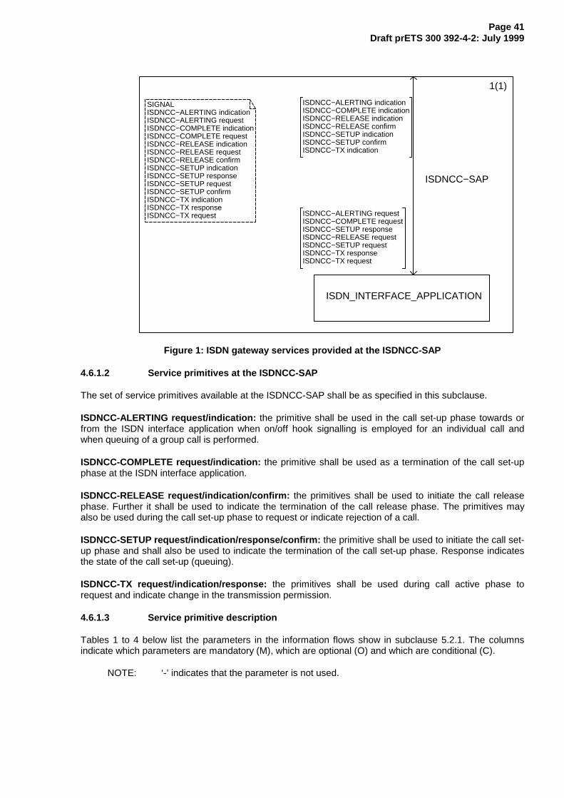
Page 41Draft prETS 300 392-4-2: July 1999
SIGNALISDNCC−ALERTING indicationISDNCC−ALERTING requestISDNCC−COMPLETE indicationISDNCC−COMPLETE requestISDNCC−RELEASE indicationISDNCC−RELEASE requestISDNCC−RELEASE confirmISDNCC−SETUP indicationISDNCC−SETUP responseISDNCC−SETUP requestISDNCC−SETUP confirmISDNCC−TX indicationISDNCC−TX responseISDNCC−TX request
1(1)
ISDN_INTERFACE_APPLICATION
ISDNCC−SAP
ISDNCC−ALERTING indicationISDNCC−COMPLETE indicationISDNCC−RELEASE indicationISDNCC−RELEASE confirmISDNCC−SETUP indicationISDNCC−SETUP confirmISDNCC−TX indication
ISDNCC−ALERTING requestISDNCC−COMPLETE requestISDNCC−SETUP responseISDNCC−RELEASE requestISDNCC−SETUP requestISDNCC−TX responseISDNCC−TX request
Figure 1: ISDN gateway services provided at the ISDNCC-SAP
4.6.1.2 Service primitives at the ISDNCC-SAP
The set of service primitives available at the ISDNCC-SAP shall be as specified in this subclause.
ISDNCC-ALERTING request/indication: the primitive shall be used in the call set-up phase towards orfrom the ISDN interface application when on/off hook signalling is employed for an individual call andwhen queuing of a group call is performed.
ISDNCC-COMPLETE request/indication: the primitive shall be used as a termination of the call set-upphase at the ISDN interface application.
ISDNCC-RELEASE request/indication/confirm: the primitives shall be used to initiate the call releasephase. Further it shall be used to indicate the termination of the call release phase. The primitives mayalso be used during the call set-up phase to request or indicate rejection of a call.
ISDNCC-SETUP request/indication/response/confirm: the primitive shall be used to initiate the call set-up phase and shall also be used to indicate the termination of the call set-up phase. Response indicatesthe state of the call set-up (queuing).
ISDNCC-TX request/indication/response: the primitives shall be used during call active phase torequest and indicate change in the transmission permission.
4.6.1.3 Service primitive description
Tables 1 to 4 below list the parameters in the information flows show in subclause 5.2.1. The columnsindicate which parameters are mandatory (M), which are optional (O) and which are conditional (C).
NOTE: ‘-’ indicates that the parameter is not used.
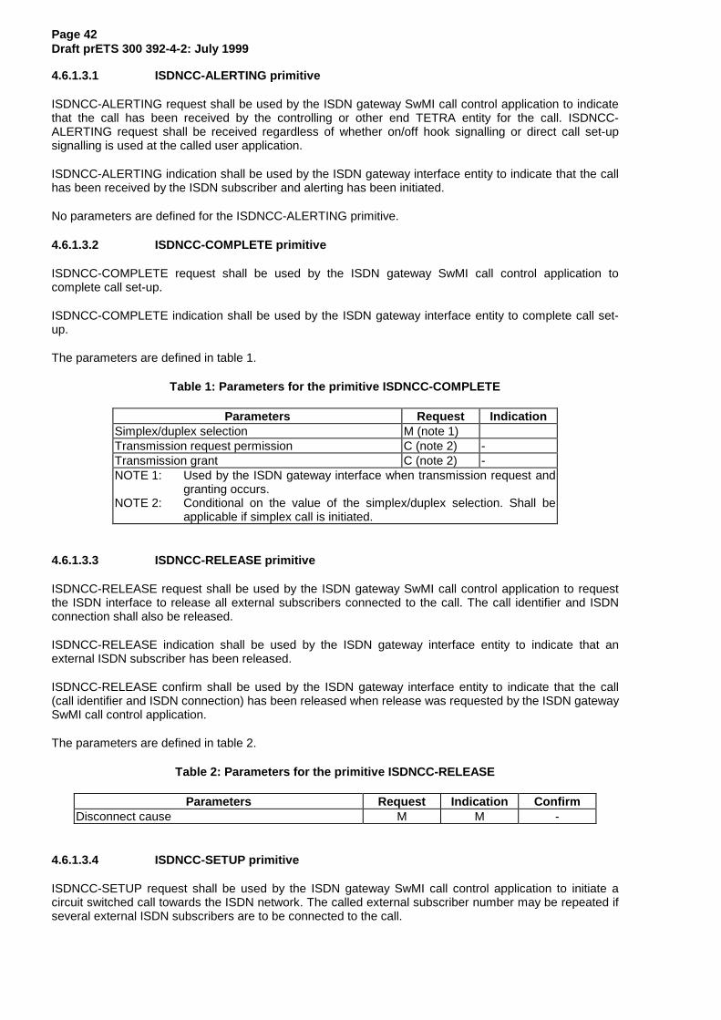
Page 42Draft prETS 300 392-4-2: July 1999
4.6.1.3.1 ISDNCC-ALERTING primitive
ISDNCC-ALERTING request shall be used by the ISDN gateway SwMI call control application to indicatethat the call has been received by the controlling or other end TETRA entity for the call. ISDNCC-ALERTING request shall be received regardless of whether on/off hook signalling or direct call set-upsignalling is used at the called user application.
ISDNCC-ALERTING indication shall be used by the ISDN gateway interface entity to indicate that the callhas been received by the ISDN subscriber and alerting has been initiated.
No parameters are defined for the ISDNCC-ALERTING primitive.
4.6.1.3.2 ISDNCC-COMPLETE primitive
ISDNCC-COMPLETE request shall be used by the ISDN gateway SwMI call control application tocomplete call set-up.
ISDNCC-COMPLETE indication shall be used by the ISDN gateway interface entity to complete call set-up.
The parameters are defined in table 1.
Table 1: Parameters for the primitive ISDNCC-COMPLETE
Parameters Request IndicationSimplex/duplex selection M (note 1)Transmission request permission C (note 2) -Transmission grant C (note 2) -NOTE 1: Used by the ISDN gateway interface when transmission request and
granting occurs.NOTE 2: Conditional on the value of the simplex/duplex selection. Shall be
applicable if simplex call is initiated.
4.6.1.3.3 ISDNCC-RELEASE primitive
ISDNCC-RELEASE request shall be used by the ISDN gateway SwMI call control application to requestthe ISDN interface to release all external subscribers connected to the call. The call identifier and ISDNconnection shall also be released.
ISDNCC-RELEASE indication shall be used by the ISDN gateway interface entity to indicate that anexternal ISDN subscriber has been released.
ISDNCC-RELEASE confirm shall be used by the ISDN gateway interface entity to indicate that the call(call identifier and ISDN connection) has been released when release was requested by the ISDN gatewaySwMI call control application.
The parameters are defined in table 2.
Table 2: Parameters for the primitive ISDNCC-RELEASE
Parameters Request Indication ConfirmDisconnect cause M M -
4.6.1.3.4 ISDNCC-SETUP primitive
ISDNCC-SETUP request shall be used by the ISDN gateway SwMI call control application to initiate acircuit switched call towards the ISDN network. The called external subscriber number may be repeated ifseveral external ISDN subscribers are to be connected to the call.
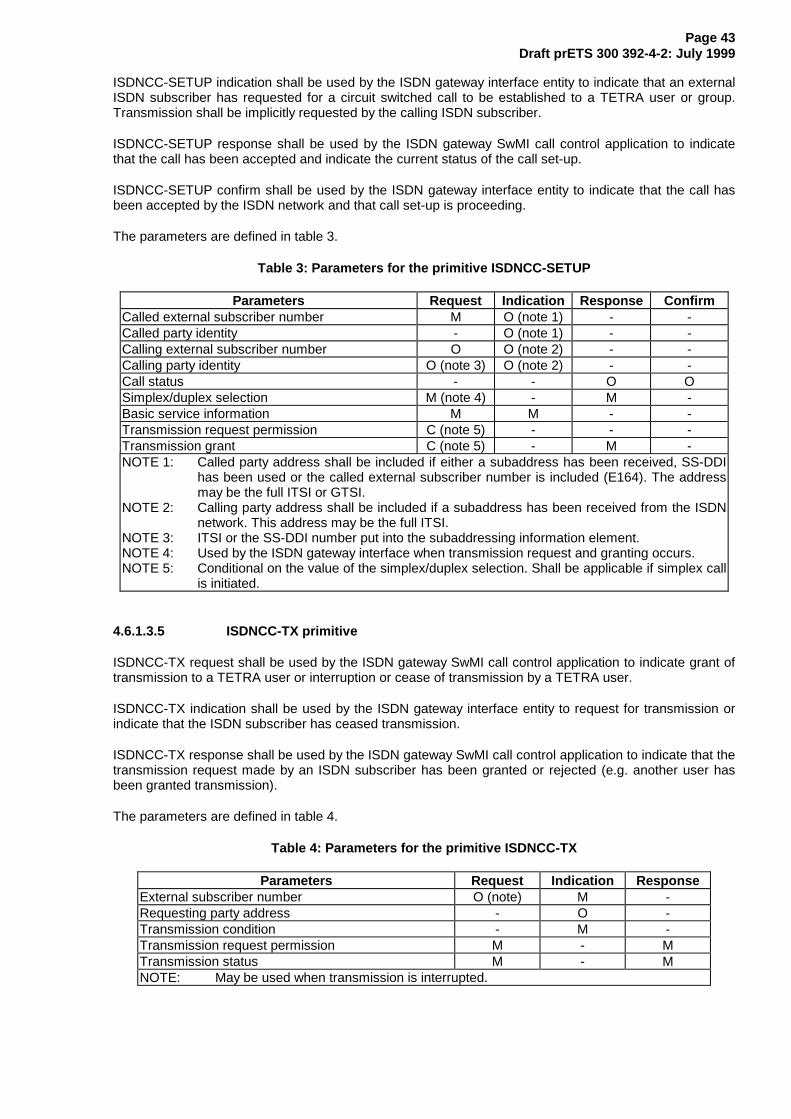
Page 43Draft prETS 300 392-4-2: July 1999
ISDNCC-SETUP indication shall be used by the ISDN gateway interface entity to indicate that an externalISDN subscriber has requested for a circuit switched call to be established to a TETRA user or group.Transmission shall be implicitly requested by the calling ISDN subscriber.
ISDNCC-SETUP response shall be used by the ISDN gateway SwMI call control application to indicatethat the call has been accepted and indicate the current status of the call set-up.
ISDNCC-SETUP confirm shall be used by the ISDN gateway interface entity to indicate that the call hasbeen accepted by the ISDN network and that call set-up is proceeding.
The parameters are defined in table 3.
Table 3: Parameters for the primitive ISDNCC-SETUP
Parameters Request Indication Response ConfirmCalled external subscriber number M O (note 1) - -Called party identity - O (note 1) - -Calling external subscriber number O O (note 2) - -Calling party identity O (note 3) O (note 2) - -Call status - - O OSimplex/duplex selection M (note 4) - M -Basic service information M M - -Transmission request permission C (note 5) - - -Transmission grant C (note 5) - M -NOTE 1: Called party address shall be included if either a subaddress has been received, SS-DDI
has been used or the called external subscriber number is included (E164). The addressmay be the full ITSI or GTSI.
NOTE 2: Calling party address shall be included if a subaddress has been received from the ISDNnetwork. This address may be the full ITSI.
NOTE 3: ITSI or the SS-DDI number put into the subaddressing information element.NOTE 4: Used by the ISDN gateway interface when transmission request and granting occurs.NOTE 5: Conditional on the value of the simplex/duplex selection. Shall be applicable if simplex call
is initiated.
4.6.1.3.5 ISDNCC-TX primitive
ISDNCC-TX request shall be used by the ISDN gateway SwMI call control application to indicate grant oftransmission to a TETRA user or interruption or cease of transmission by a TETRA user.
ISDNCC-TX indication shall be used by the ISDN gateway interface entity to request for transmission orindicate that the ISDN subscriber has ceased transmission.
ISDNCC-TX response shall be used by the ISDN gateway SwMI call control application to indicate that thetransmission request made by an ISDN subscriber has been granted or rejected (e.g. another user hasbeen granted transmission).
The parameters are defined in table 4.
Table 4: Parameters for the primitive ISDNCC-TX
Parameters Request Indication ResponseExternal subscriber number O (note) M -Requesting party address - O -Transmission condition - M -Transmission request permission M - MTransmission status M - MNOTE: May be used when transmission is interrupted.
Page 44Draft prETS 300 392-4-2: July 1999
4.6.1.4 Parameter descriptions
This subclause defines parameter values for the primitives described in subclause 5.2.2.
Basic service information (a set of parameters) =circuit mode service;encryption flag.
Call status =0 call is progressing;1 call is queued.
Called / Calling external subscriber number =Up to 24 digits. Each digit shall be one of the following:
0 digit 0;etc. etc...;9 digit 9;10 digit *;11 digit #;12 digit +.
Called gateway SSI =Short Subscriber Identity.
Called / Calling party identity =Up to 14-15 DTMF digits. Each digit shall be one of the following:
0 digit 0;etc. etc...;9 digit 9;10 digit *;11 digit #;12 digit +.
Circuit mode service =0 reserved;1 speech service.
Disconnect cause =0 cause not defined or unknown;1 user requested disconnect;2 called party busy;3 called party not reachable;4 called party does not support encryption;5 congestion in infrastructure;6 not allowed traffic case;7 incompatible traffic case;8 requested service not available;9 pre-emptive use of resource;10 invalid call identifier;11 call rejected by the called party;12 no idle air interface call control protocol sub-entity;13 expiry of timer;14 SwMI requested disconnection;15 acknowledged service not completed;16 reserved;ect. ect..;28 external resources unavailable (i.e. no route to destination);29 invalid number.
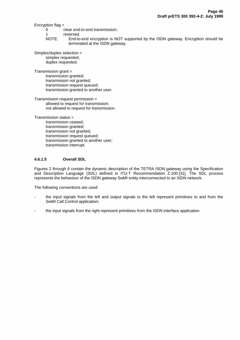
Page 45Draft prETS 300 392-4-2: July 1999
Encryption flag =0 clear end-to-end transmission;1 reserved.NOTE: End-to-end encryption is NOT supported by the ISDN gateway. Encryption should be
terminated at the ISDN gateway.
Simplex/duplex selection =simplex requested;duplex requested.
Transmission grant =transmission granted;transmission not granted;transmission request queued;transmission granted to another user.
Transmission request permission =allowed to request for transmission;not allowed to request for transmission.
Transmission status =transmission ceased;transmission granted;transmission not granted;transmission request queued;transmission granted to another user;transmission interrupt.
4.6.1.5 Overall SDL
Figures 2 through 6 contain the dynamic description of the TETRA ISDN gateway using the Specificationand Description Language (SDL) defined in ITU-T Recommendation Z.100 [31]. The SDL processrepresents the behaviour of the ISDN gateway SwMI entity interconnected to an ISDN network.
The following conventions are used:
- the input signals from the left and output signals to the left represent primitives to and from theSwMI Call Control application;
- the input signals from the right represent primitives from the ISDN interface application.
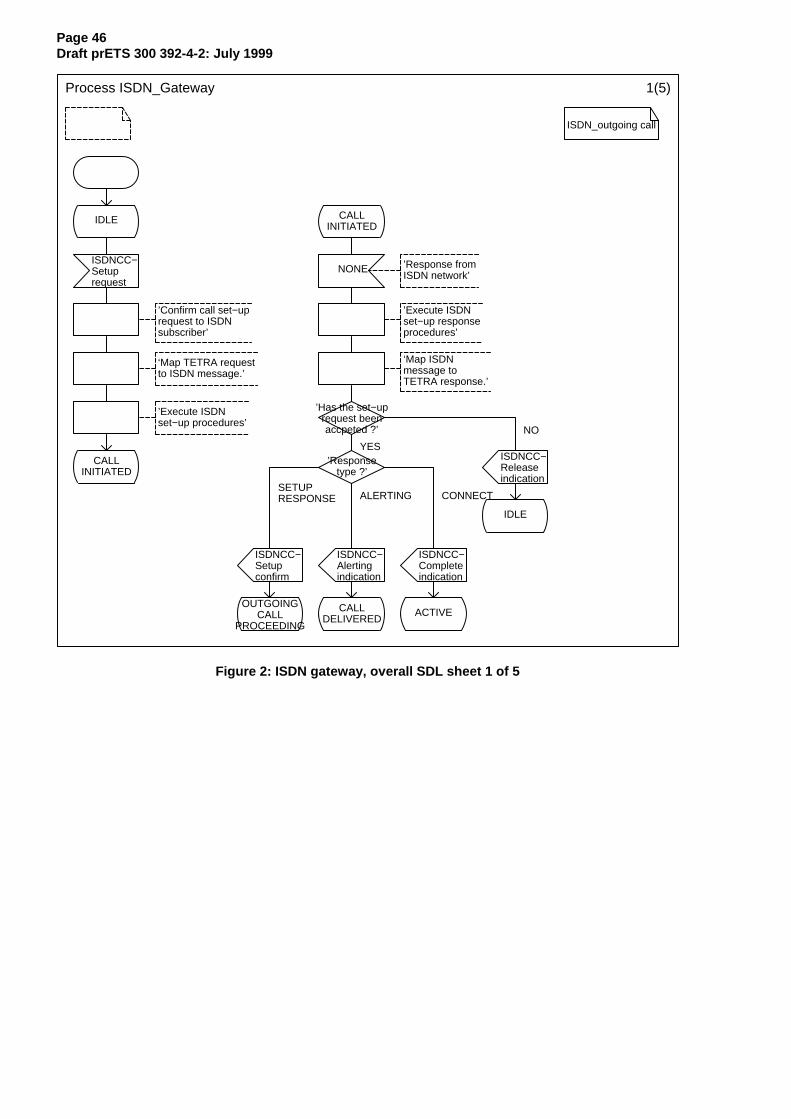
Page 46Draft prETS 300 392-4-2: July 1999
Process ISDN_Gateway 1(5)
ISDN_outgoing call
IDLE CALLINITIATED
ISDNCC−Setuprequest
NONE ’Response fromISDN network’
’Confirm call set−uprequest to ISDN subscriber’
’Execute ISDNset−up responseprocedures’
‘Map TETRA requestto ISDN message.’
‘Map ISDN message to TETRA response.’
’Execute ISDNset−up procedures’
’Has the set−uprequest beenaccpeted ?’
CALLINITIATED
’Responsetype ?’
ISDNCC−Releaseindication
IDLE
ISDNCC−Setup confirm
ISDNCC−Alerting indication
ISDNCC−Complete indication
OUTGOINGCALL
PROCEEDING
CALLDELIVERED
ACTIVE
YES
NO
SETUP RESPONSE ALERTING CONNECT
Figure 2: ISDN gateway, overall SDL sheet 1 of 5
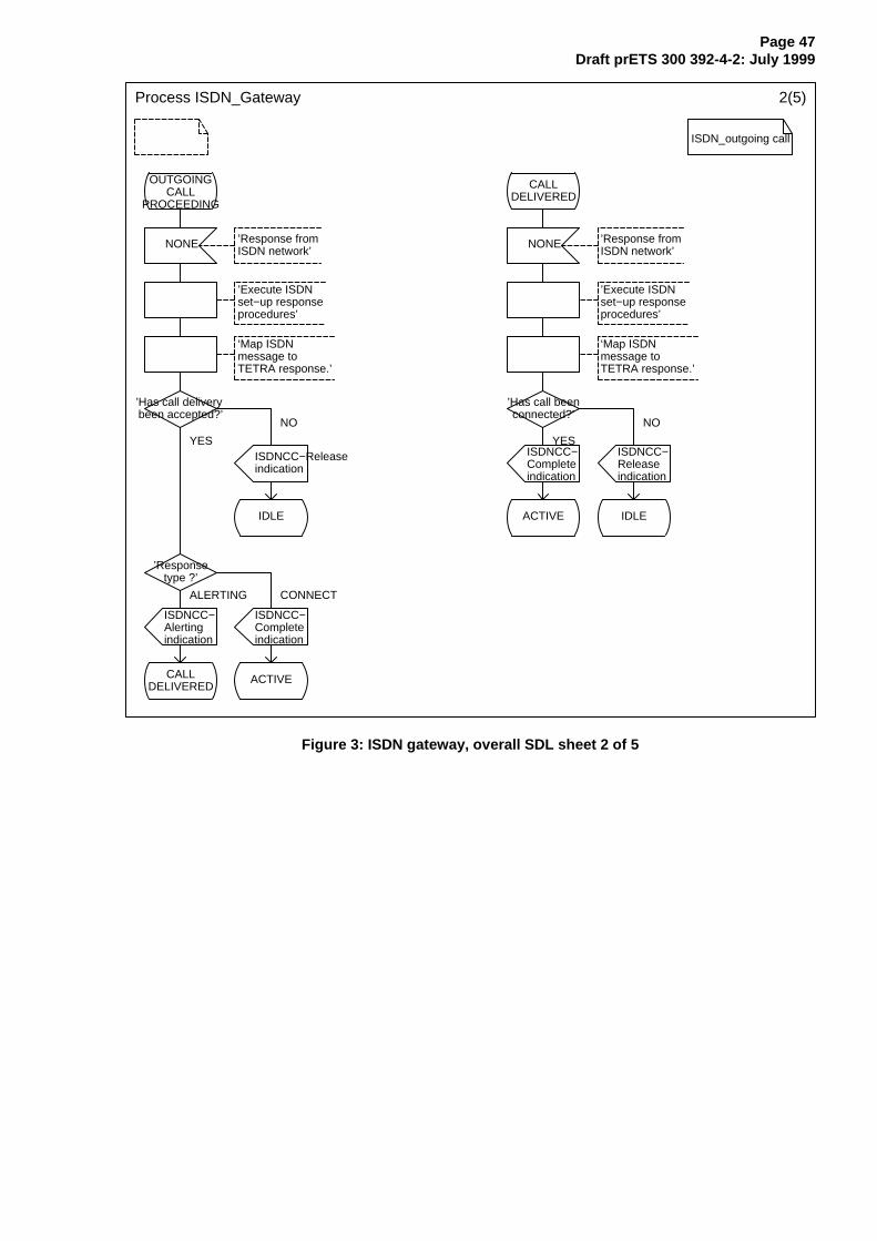
Page 47Draft prETS 300 392-4-2: July 1999
Process ISDN_Gateway 2(5)
ISDN_outgoing call
OUTGOINGCALL
PROCEEDING
CALLDELIVERED
NONE ’Response fromISDN network’
NONE ’Response fromISDN network’
’Execute ISDNset−up responseprocedures’
’Execute ISDNset−up responseprocedures’
‘Map ISDN message to TETRA response.’
‘Map ISDN message to TETRA response.’
’Has call delivery been accepted?’
’Has call beenconnected?’
ISDNCC−Releaseindication
ISDNCC−Complete indication
ISDNCC−Releaseindication
IDLE ACTIVE IDLE
’Responsetype ?’
ISDNCC−Alerting indication
ISDNCC−Complete indication
CALLDELIVERED
ACTIVE
NO
YES YES
NO
ALERTING CONNECT
Figure 3: ISDN gateway, overall SDL sheet 2 of 5
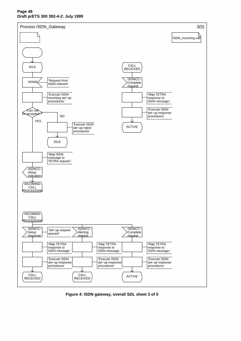
Page 48Draft prETS 300 392-4-2: July 1999
Process ISDN_Gateway 3(5)
ISDN_incoming call
IDLE CALLRECEIVED
NONE ’Request fromISDN network’
ISDNCC−Completerequest
’Execute ISDNincoming set−upprocedures’
‘Map TETRAresponse toISDN message.’
’Can callbe accepted ?’
’Execute ISDNset−up responseprocedures’
’Execute ISDNset−up rejectprocedures’
ACTIVE
IDLE
‘Map ISDN message to TETRA request.’
ISDNCC−Setupindication
INCOMINGCALL
PROCEEDING
INCOMINGCALL
PROCEEDING
ISDNCC−Setupresponse
’Set−up requestqueued’
ISDNCC−Alertingrequest
ISDNCC−Completerequest
‘Map TETRAresponse toISDN message.’
‘Map TETRAresponse toISDN message.’
‘Map TETRAresponse toISDN message.’
’Execute ISDNset−up responseprocedures’
’Execute ISDNset−up responseprocedures’
’Execute ISDNset−up responseprocedures’
CALLRECEIVED
CALLRECEIVED
ACTIVE
NO
YES
Figure 4: ISDN gateway, overall SDL sheet 3 of 5
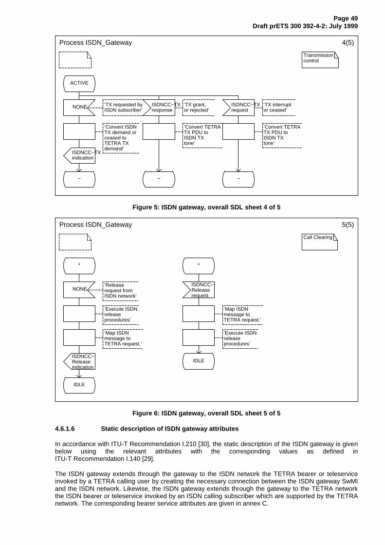
Page 49Draft prETS 300 392-4-2: July 1999
Process ISDN_Gateway 4(5)
Transmissioncontrol
ACTIVE
NONE ’TX requested byISDN subscriber’
ISDNCC−TXresponse
’TX grant,or rejected’
ISDNCC−TXrequest
’TX interrupt or ceased’
’Convert ISDNTX demand or ceased toTETRA TX demand’
’Convert TETRATX PDU toISDN TX tone’
’Convert TETRATX PDU toISDN TX tone’
ISDNCC−TXindication
− − −
Figure 5: ISDN gateway, overall SDL sheet 4 of 5
Process ISDN_Gateway 5(5)
Call Clearing
* *
NONE’Releaserequest fromISDN network’
ISDNCC−Releaserequest
’Execute ISDNreleaseprocedures’
‘Map ISDN message to TETRA request.’
‘Map ISDN message to TETRA request.’
’Execute ISDNreleaseprocedures’
ISDNCC−Releaseindication
IDLE
IDLE
Figure 6: ISDN gateway, overall SDL sheet 5 of 5
4.6.1.6 Static description of ISDN gateway attributes
In accordance with ITU-T Recommendation I.210 [30], the static description of the ISDN gateway is givenbelow using the relevant attributes with the corresponding values as defined inITU-T Recommendation I.140 [29].
The ISDN gateway extends through the gateway to the ISDN network the TETRA bearer or teleserviceinvoked by a TETRA calling user by creating the necessary connection between the ISDN gateway SwMIand the ISDN network. Likewise, the ISDN gateway extends through the gateway to the TETRA networkthe ISDN bearer or teleservice invoked by an ISDN calling subscriber which are supported by the TETRAnetwork. The corresponding bearer service attributes are given in annex C.
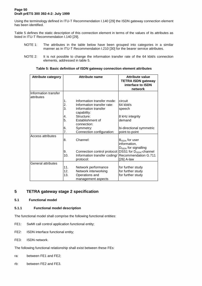
Page 50Draft prETS 300 392-4-2: July 1999
Using the terminology defined in ITU-T Recommendation I.140 [29] the ISDN gateway connection elementhas been identified.
Table 5 defines the static description of this connection element in terms of the values of its attributes aslisted in ITU-T Recommendation I.140 [29].
NOTE 1: The attributes in the table below have been grouped into categories in a similarmanner as in ITU-T Recommendation I.210 [30] for the bearer service attributes.
NOTE 2: It is not possible to change the information transfer rate of the 64 kbit/s connectionelements, addressed in table 5.
Table 5: Basic definition of ISDN gateway connection element attributes
Attribute category Attribute name Attribute valueTETRA ISDN gateway
interface to ISDNnetwork
Information transferattributes
1. Information transfer mode: circuit2. Information transfer rate: 64 kbit/s3. Information transfer
capability:speech
4. Structure: 8 kHz integrity5. Establishment of
connection:demand
6. Symmetry: bi-directional symmetric7. Connection configuration: point-to-point
Access attributes8. Channel: BISDN for user
information,DISDN for signalling
9. Connection control protocol: DSS1 for DISDN-channel10. Information transfer coding/
protocol:Recommendation G.711[26] A-law
General attributes11. Network performance for further study12. Network interworking for further study13. Operations and
management aspectsfor further study
5 TETRA gateway stage 2 specification
5.1 Functional model
5.1.1 Functional model description
The functional model shall comprise the following functional entities:
FE1: SwMI call control application functional entity;
FE2: ISDN interface functional entity;
FE3: ISDN network.
The following functional relationship shall exist between these FEs:
ra: between FE1 and FE2;
rb: between FE2 and FE3.
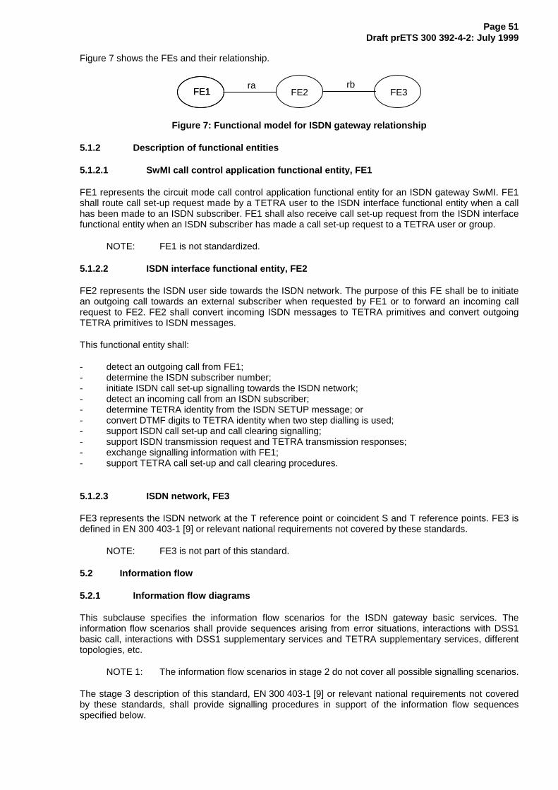
Page 51Draft prETS 300 392-4-2: July 1999
Figure 7 shows the FEs and their relationship.
FE1 FE3ra
FE1 FE2rb
Figure 7: Functional model for ISDN gateway relationship
5.1.2 Description of functional entities
5.1.2.1 SwMI call control application functional entity, FE1
FE1 represents the circuit mode call control application functional entity for an ISDN gateway SwMI. FE1shall route call set-up request made by a TETRA user to the ISDN interface functional entity when a callhas been made to an ISDN subscriber. FE1 shall also receive call set-up request from the ISDN interfacefunctional entity when an ISDN subscriber has made a call set-up request to a TETRA user or group.
NOTE: FE1 is not standardized.
5.1.2.2 ISDN interface functional entity, FE2
FE2 represents the ISDN user side towards the ISDN network. The purpose of this FE shall be to initiatean outgoing call towards an external subscriber when requested by FE1 or to forward an incoming callrequest to FE2. FE2 shall convert incoming ISDN messages to TETRA primitives and convert outgoingTETRA primitives to ISDN messages.
This functional entity shall:
- detect an outgoing call from FE1;- determine the ISDN subscriber number;- initiate ISDN call set-up signalling towards the ISDN network;- detect an incoming call from an ISDN subscriber;- determine TETRA identity from the ISDN SETUP message; or- convert DTMF digits to TETRA identity when two step dialling is used;- support ISDN call set-up and call clearing signalling;- support ISDN transmission request and TETRA transmission responses;- exchange signalling information with FE1;- support TETRA call set-up and call clearing procedures.
5.1.2.3 ISDN network, FE3
FE3 represents the ISDN network at the T reference point or coincident S and T reference points. FE3 isdefined in EN 300 403-1 [9] or relevant national requirements not covered by these standards.
NOTE: FE3 is not part of this standard.
5.2 Information flow
5.2.1 Information flow diagrams
This subclause specifies the information flow scenarios for the ISDN gateway basic services. Theinformation flow scenarios shall provide sequences arising from error situations, interactions with DSS1basic call, interactions with DSS1 supplementary services and TETRA supplementary services, differenttopologies, etc.
NOTE 1: The information flow scenarios in stage 2 do not cover all possible signalling scenarios.
The stage 3 description of this standard, EN 300 403-1 [9] or relevant national requirements not coveredby these standards, shall provide signalling procedures in support of the information flow sequencesspecified below.
Page 52Draft prETS 300 392-4-2: July 1999
Within a column representing an ISDN gateway functional entity, the numbers refer to functional entityactions listed in 5.3. The following abbreviations are used:
- req: request;- ind: indication;- resp: response;- conf: confirmation.
Columns have been made in the information flows below to represent the signalling between the ISDNnetwork (FE3) and the ISDN interface functional entity FE2 and interactions between FE2 and the ISDNgateway SwMI call control application functional entity, FE1. The actions of the ISDN network and of FE1are outside TETRA standardization. Therefore, no functional entity actions have been listed insubclause 5.3 for these interfaces.
NOTE 2: Actions performed by the ISDN network are described in the standards,EN 300 403-1 [9] or relevant national requirements not covered by these standards.
NOTE 3: Actions within the call control application of a SwMI are not standardized however,implicit behavior is assumed from the air interface standard ETS 300 392-2 [12] andfrom the ISI standard, ETS 300 392-3 [13].
5.2.1.1 Successful call set-up to an ISDN subscriber
There shall be no distinction between on/off hook signalling and direct call set-up signalling. FE2 is notinformed of which hook method selection that has been chosen by the calling user or the TETRA SwMI.
Figure 8 shows a successful information flow sequence for an individual or group call set-up to an ISDNsubscriber through an ISDN gateway. The external subscriber number is defined in the TETRAISDNCC-SETUP request primitive.
For individual calls, transmission is granted per default to the ISDN subscriber for outgoing calls and to theTETRA user for incoming calls. For a group call, transmission is granted per default to the ISDNsubscriber for incoming calls and to the TETRA user for outgoing calls.
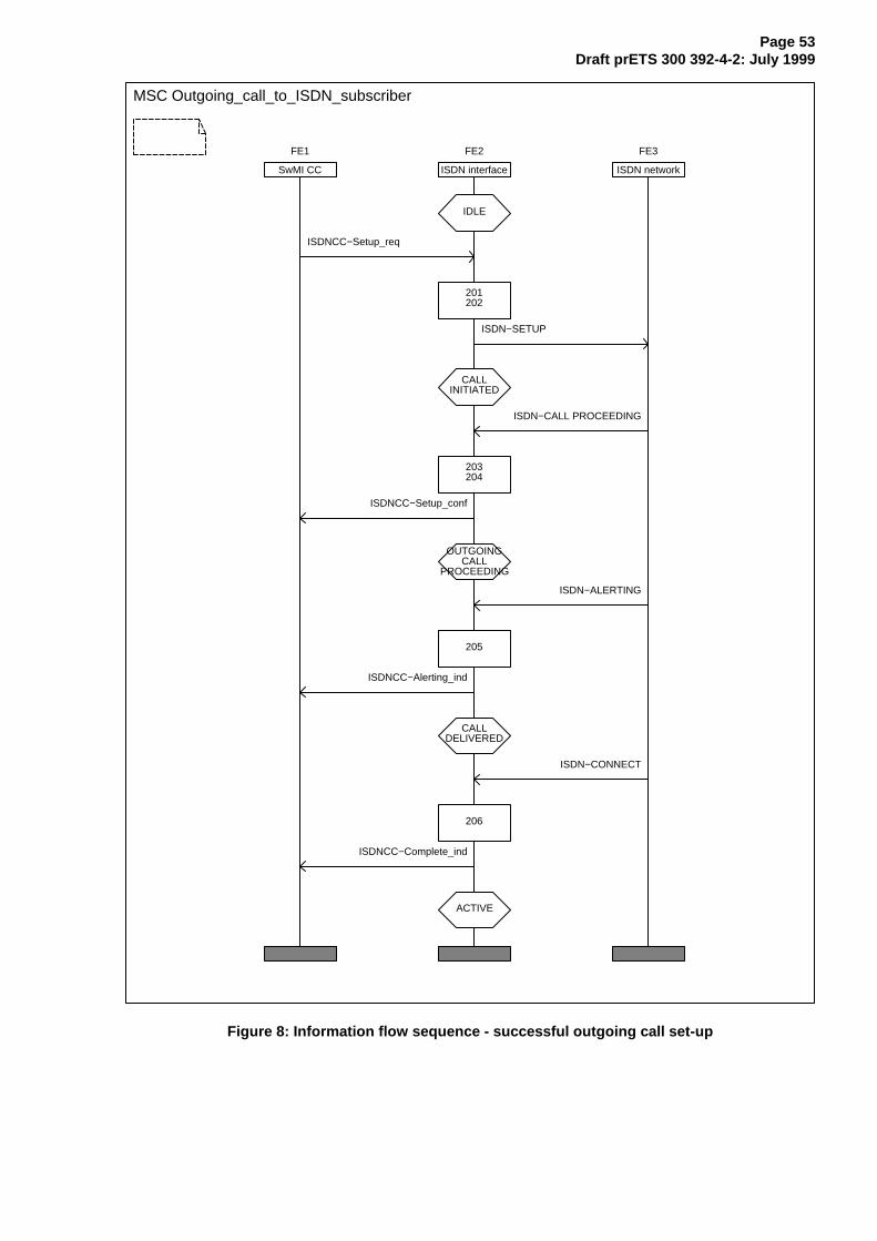
Page 53Draft prETS 300 392-4-2: July 1999
MSC Outgoing_call_to_ISDN_subscriber
FE1
SwMI CC
FE2
ISDN interface
FE3
ISDN network
IDLE
ISDNCC−Setup_req
201202
ISDN−SETUP
CALLINITIATED
ISDN−CALL PROCEEDING
203204
ISDNCC−Setup_conf
OUTGOINGCALL
PROCEEDING
ISDN−ALERTING
205
ISDNCC−Alerting_ind
CALLDELIVERED
ISDN−CONNECT
206
ISDNCC−Complete_ind
ACTIVE
Figure 8: Information flow sequence - successful outgoing call set-up

Page 54Draft prETS 300 392-4-2: July 1999
5.2.1.2 Successful call set-up from an ISDN subscriber over the ISDN gateway
Figures 9 and 10 show a successful information flow sequence for call set-up from an ISDN subscriberthrough an ISDN gateway. The called TETRA user or TETRA group identity is defined:
- by the called party subaddress information element of the ISDN SETUP message when the ISDNSubaddressing supplementary service is used;
- in the called party number information element of the ISDN SETUP message when the ISDN DirectDial In supplementary service is used; or
- received in-band (DTMF digits) when two stage dialling is used.
The following flows shall apply for individual and group calls where the calling user is an ISDN subscriber.
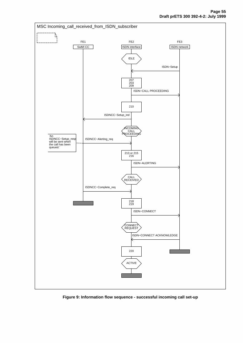
Page 55Draft prETS 300 392-4-2: July 1999
MSC Incoming_call_received_from_ISDN_subscriber
FE1
SwMI CC
FE2
ISDN interface
FE3
ISDN network
IDLE
ISDN−Setup
207203209
ISDN−CALL PROCEEDING
210
ISDNCC−Setup_ind
INCOMINGCALL
PROCEEDING
ISDNCC−Alerting_req
213 or 215216
ISDN−ALERTING
CALLRECEIVED
ISDNCC−Complete_req
218219
ISDN−CONNECT
CONNECTREQUEST
ISDN−CONNECT ACKNOWLEDGE
220
ACTIVE
’An ISDNCC−Setup_respwill be sent whenthe call has been queued.’
Figure 9: Information flow sequence - successful incoming call set-up
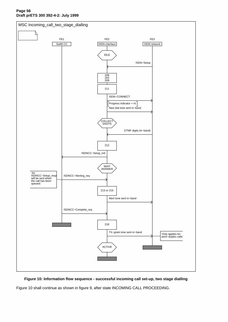
Page 56Draft prETS 300 392-4-2: July 1999
MSC Incoming_call_two_stage_dialling
FE1
SwMI CC
FE2
ISDN interface
FE3
ISDN network
IDLE
ISDN−Setup
208203209
211
ISDN−CONNECT
Progress indicator = #1
New dial tone sent in−band
COLLECTDIGITS
DTMF digits (in−band)
212
ISDNCC−Setup_ind
WAITANSWER
ISDNCC−Alerting_req
213 or 215
Alert tone sent in−band
ISDNCC−Complete_req
218
TX−grant tone sent in−band
ACTIVE
’Only applies forsemi−duplex calls’
’AnISDNCC−Setup_respwill be sent whenthe call has beenqueued.’
Figure 10: Information flow sequence - successful incoming call set-up, two stage dialling
Figure 10 shall continue as shown in figure 9, after state INCOMING CALL PROCEEDING.
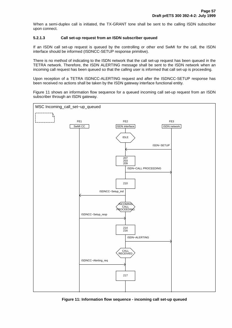
Page 57Draft prETS 300 392-4-2: July 1999
When a semi-duplex call is initiated, the TX-GRANT tone shall be sent to the calling ISDN subscriberupon connect.
5.2.1.3 Call set-up request from an ISDN subscriber queued
If an ISDN call set-up request is queued by the controlling or other end SwMI for the call, the ISDNinterface should be informed (ISDNCC-SETUP response primitive).
There is no method of indicating to the ISDN network that the call set-up request has been queued in theTETRA network. Therefore, the ISDN ALERTING message shall be sent to the ISDN network when anincoming call request has been queued so that the calling user is informed that call set-up is proceeding.
Upon reception of a TETRA ISDNCC-ALERTING request and after the ISDNCC-SETUP response hasbeen received no actions shall be taken by the ISDN gateway interface functional entity.
Figure 11 shows an information flow sequence for a queued incoming call set-up request from an ISDNsubscriber through an ISDN gateway.
MSC Incoming_call_set−up_queued
FE1
SwMI CC
FE2
ISDN interface
FE3
ISDN network
IDLE
ISDN−SETUP
207203209
ISDN−CALL PROCEEDING
210
ISDNCC−Setup_ind
INCOMINGCALL
PROCEEDING
ISDNCC−Setup_resp
214216
ISDN−ALERTING
CALLRECEIVED
ISDNCC−Alerting_req
217
Figure 11: Information flow sequence - incoming call set-up queued

Page 58Draft prETS 300 392-4-2: July 1999
Figure 11 shall continue as shown in figure 9, state CALL RECEIVED.
5.2.1.4 Unsuccessful call set-up to an ISDN subscriber
Figure 12 shows an unsuccessful call set-up information flow sequence to an ISDN subscriber through anISDN gateway. The ISDN subscriber is busy.
This flow shall apply for individual and group calls where the called user is an ISDN subscriber.
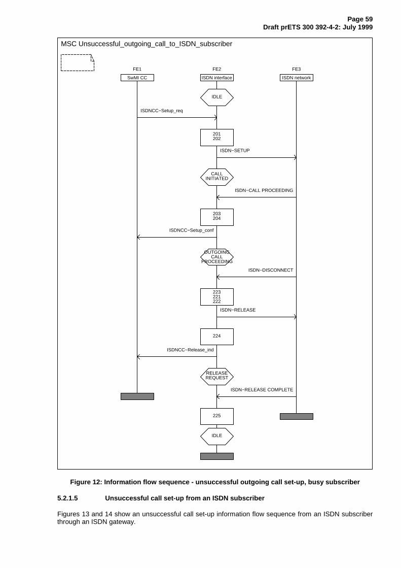
Page 59Draft prETS 300 392-4-2: July 1999
MSC Unsuccessful_outgoing_call_to_ISDN_subscriber
FE1
SwMI CC
FE2
ISDN interface
FE3
ISDN network
IDLE
ISDNCC−Setup_req
201202
ISDN−SETUP
CALLINITIATED
ISDN−CALL PROCEEDING
203204
ISDNCC−Setup_conf
OUTGOINGCALL
PROCEEDING
ISDN−DISCONNECT
223221222
ISDN−RELEASE
224
ISDNCC−Release_ind
RELEASEREQUEST
ISDN−RELEASE COMPLETE
225
IDLE
Figure 12: Information flow sequence - unsuccessful outgoing call set-up, busy subscriber
5.2.1.5 Unsuccessful call set-up from an ISDN subscriber
Figures 13 and 14 show an unsuccessful call set-up information flow sequence from an ISDN subscriberthrough an ISDN gateway.
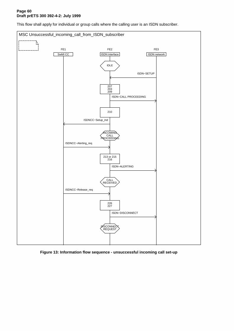
Page 60Draft prETS 300 392-4-2: July 1999
This flow shall apply for individual or group calls where the calling user is an ISDN subscriber.
MSC Unsuccessful_incoming_call_from_ISDN_subscriber
FE1
SwMI CC
FE2
ISDN interface
FE3
ISDN network
IDLE
ISDN−SETUP
207203209
ISDN−CALL PROCEEDING
210
ISDNCC−Setup_ind
INCOMINGCALL
PROCEEDING
ISDNCC−Alerting_req
213 or 215216
ISDN−ALERTING
CALLRECEIVED
ISDNCC−Release_req
226227
ISDN−DISCONNECT
DISCONNECTREQUEST
Figure 13: Information flow sequence - unsuccessful incoming call set-up
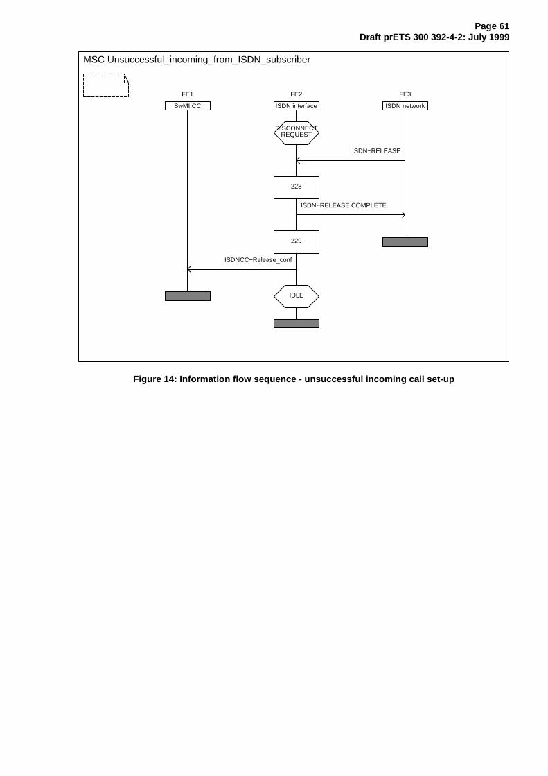
Page 61Draft prETS 300 392-4-2: July 1999
MSC Unsuccessful_incoming_from_ISDN_subscriber
FE1
SwMI CC
FE2
ISDN interface
FE3
ISDN network
DISCONNECTREQUEST
ISDN−RELEASE
228
ISDN−RELEASE COMPLETE
229
ISDNCC−Release_conf
IDLE
Figure 14: Information flow sequence - unsuccessful incoming call set-up
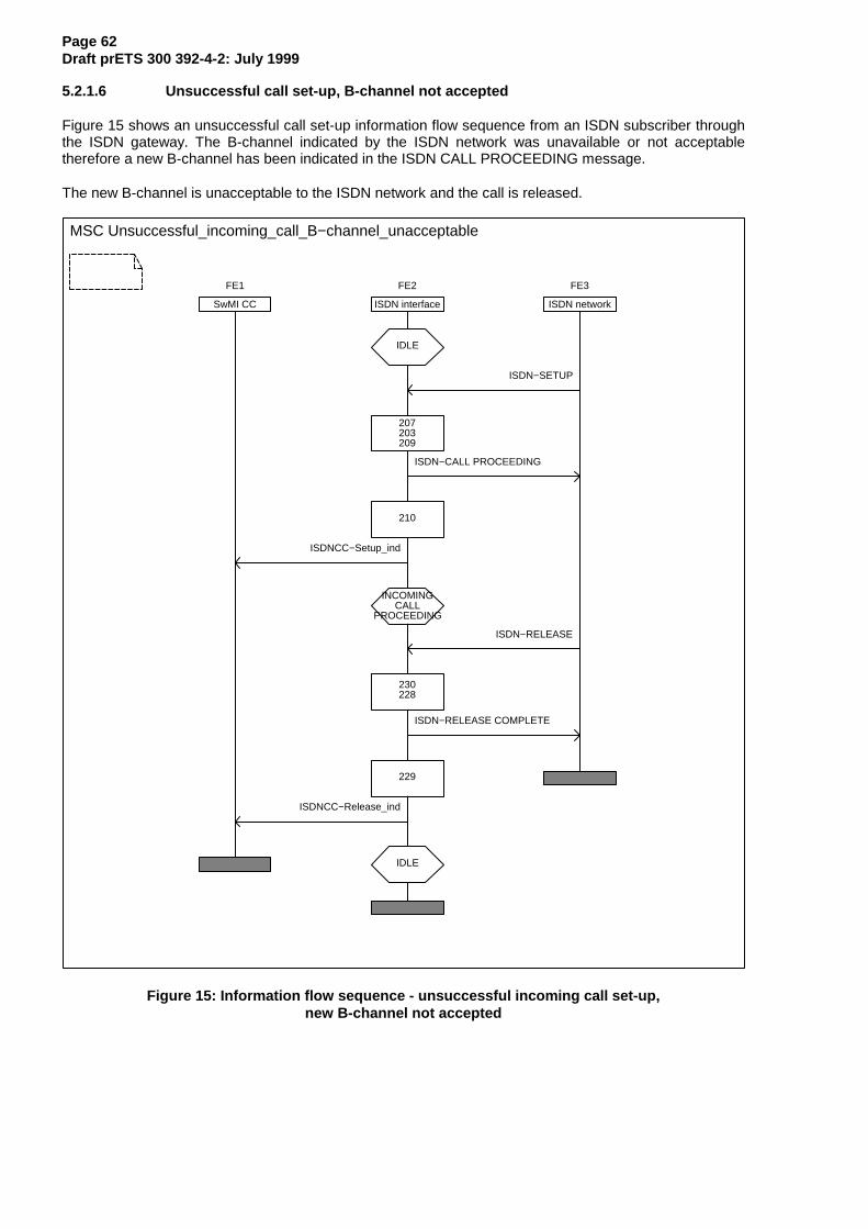
Page 62Draft prETS 300 392-4-2: July 1999
5.2.1.6 Unsuccessful call set-up, B-channel not accepted
Figure 15 shows an unsuccessful call set-up information flow sequence from an ISDN subscriber throughthe ISDN gateway. The B-channel indicated by the ISDN network was unavailable or not acceptabletherefore a new B-channel has been indicated in the ISDN CALL PROCEEDING message.
The new B-channel is unacceptable to the ISDN network and the call is released.
MSC Unsuccessful_incoming_call_B−channel_unacceptable
FE1
SwMI CC
FE2
ISDN interface
FE3
ISDN network
IDLE
ISDN−SETUP
207203209
ISDN−CALL PROCEEDING
210
ISDNCC−Setup_ind
INCOMINGCALL
PROCEEDING
ISDN−RELEASE
230228
ISDN−RELEASE COMPLETE
229
ISDNCC−Release_ind
IDLE
Figure 15: Information flow sequence - unsuccessful incoming call set-up,new B-channel not accepted
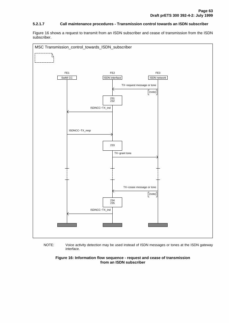
Page 63Draft prETS 300 392-4-2: July 1999
5.2.1.7 Call maintenance procedures - Transmission control towards an ISDN subscriber
Figure 16 shows a request to transmit from an ISDN subscriber and cease of transmission from the ISDNsubscriber.
MSC Transmission_control_towards_ISDN_subscriber
FE1
SwMI CC
FE2
ISDN interface
FE3
ISDN network
TX−request message or tone
(note)
231232
ISDNCC−TX_ind
ISDNCC−TX_resp
233
TX−grant tone
TX−cease message or tone
(note)
234235
ISDNCC−TX_ind
NOTE: Voice activity detection may be used instead of ISDN messages or tones at the ISDN gatewayinterface.
Figure 16: Information flow sequence - request and cease of transmissionfrom an ISDN subscriber
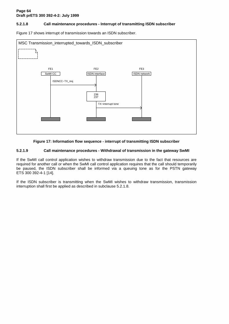
Page 64Draft prETS 300 392-4-2: July 1999
5.2.1.8 Call maintenance procedures - Interrupt of transmitting ISDN subscriber
Figure 17 shows interrupt of transmission towards an ISDN subscriber.
MSC Transmission_interrupted_towards_ISDN_subscriber
FE1
SwMI CC
FE2
ISDN interface
FE3
ISDN network
ISDNCC−TX_req
236237
TX−interrupt tone
Figure 17: Information flow sequence - interrupt of transmitting ISDN subscriber
5.2.1.9 Call maintenance procedures - Withdrawal of transmission in the gateway SwMI
If the SwMI call control application wishes to withdraw transmission due to the fact that resources arerequired for another call or when the SwMI call control application requires that the call should temporarilybe paused, the ISDN subscriber shall be informed via a queuing tone as for the PSTN gatewayETS 300 392-4-1 [14].
If the ISDN subscriber is transmitting when the SwMI wishes to withdraw transmission, transmissioninterruption shall first be applied as described in subclause 5.2.1.8.
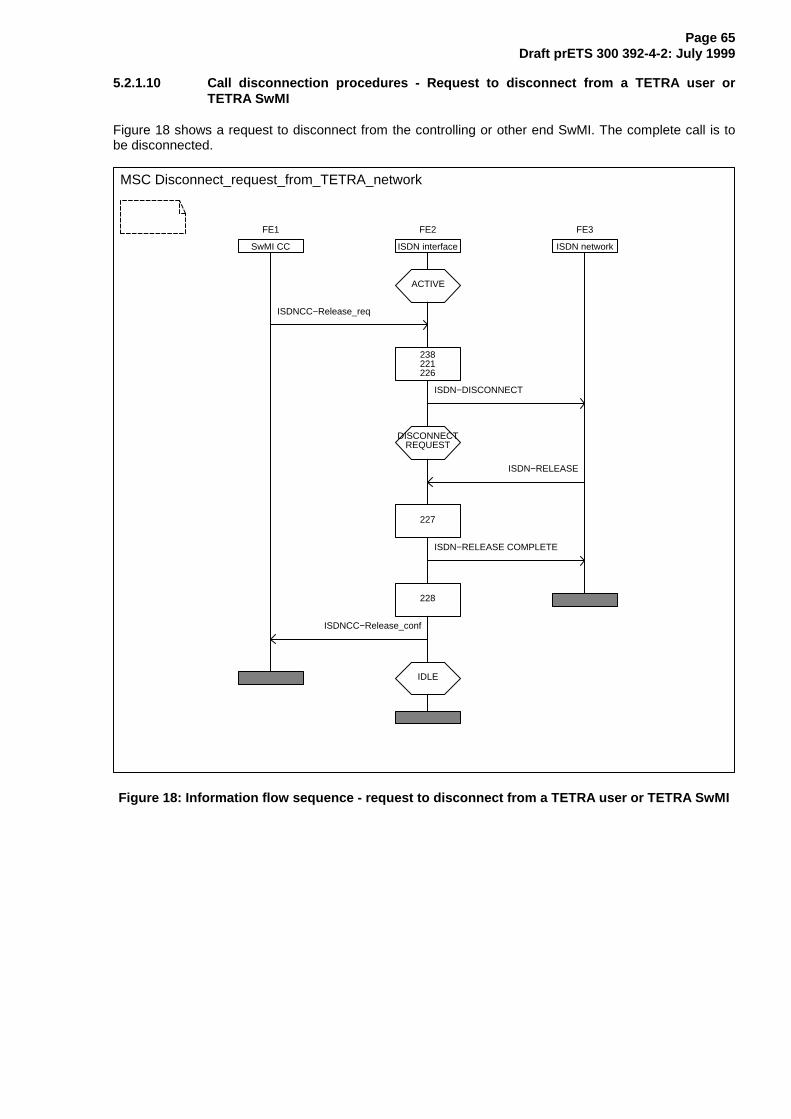
Page 65Draft prETS 300 392-4-2: July 1999
5.2.1.10 Call disconnection procedures - Request to disconnect from a TETRA user orTETRA SwMI
Figure 18 shows a request to disconnect from the controlling or other end SwMI. The complete call is tobe disconnected.
MSC Disconnect_request_from_TETRA_network
FE1
SwMI CC
FE2
ISDN interface
FE3
ISDN network
ACTIVE
ISDNCC−Release_req
238221226
ISDN−DISCONNECT
DISCONNECTREQUEST
ISDN−RELEASE
227
ISDN−RELEASE COMPLETE
228
ISDNCC−Release_conf
IDLE
Figure 18: Information flow sequence - request to disconnect from a TETRA user or TETRA SwMI
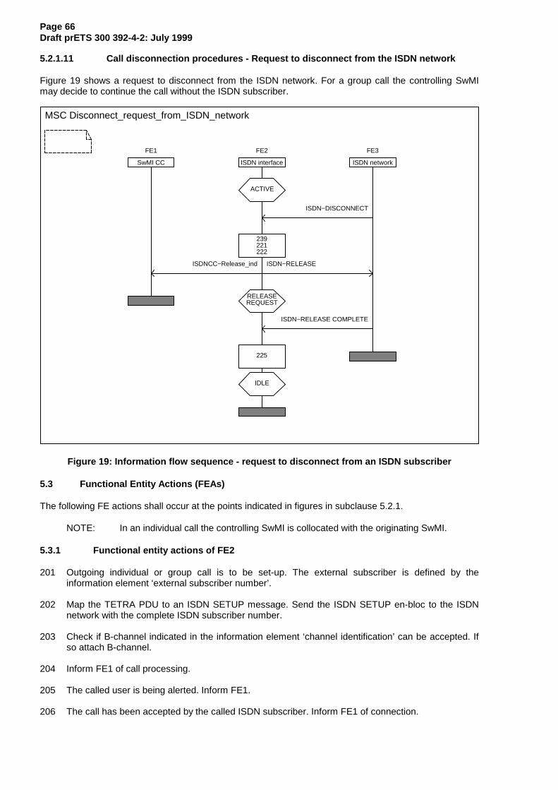
Page 66Draft prETS 300 392-4-2: July 1999
5.2.1.11 Call disconnection procedures - Request to disconnect from the ISDN network
Figure 19 shows a request to disconnect from the ISDN network. For a group call the controlling SwMImay decide to continue the call without the ISDN subscriber.
MSC Disconnect_request_from_ISDN_network
FE1
SwMI CC
FE2
ISDN interface
FE3
ISDN network
ACTIVE
ISDN−DISCONNECT
239221222
ISDNCC−Release_ind ISDN−RELEASE
RELEASEREQUEST
ISDN−RELEASE COMPLETE
225
IDLE
Figure 19: Information flow sequence - request to disconnect from an ISDN subscriber
5.3 Functional Entity Actions (FEAs)
The following FE actions shall occur at the points indicated in figures in subclause 5.2.1.
NOTE: In an individual call the controlling SwMI is collocated with the originating SwMI.
5.3.1 Functional entity actions of FE2
201 Outgoing individual or group call is to be set-up. The external subscriber is defined by theinformation element ‘external subscriber number’.
202 Map the TETRA PDU to an ISDN SETUP message. Send the ISDN SETUP en-bloc to the ISDNnetwork with the complete ISDN subscriber number.
203 Check if B-channel indicated in the information element ‘channel identification’ can be accepted. Ifso attach B-channel.
204 Inform FE1 of call processing.
205 The called user is being alerted. Inform FE1.
206 The call has been accepted by the called ISDN subscriber. Inform FE1 of connection.
Page 67Draft prETS 300 392-4-2: July 1999
207 Incoming call is to be set-up. The external subscriber may be identified by the information element‘calling party number’ and ‘calling party subaddress’. The TETRA user or group is identified by theinformation element ‘called party number’ and possible the ‘called party subaddress’ informationelement.
208 Incoming call is to be set-up. The external subscriber may be identified by the information element‘calling party number’ and ‘calling party subaddress’. The TETRA user or group address has notbeen received. Two stage dialling is to be performed.
209 If an alternative B-channel may be indicated and the given B-channel is not acceptable, indicatenew alternative.
210 Map the ISDN SETUP message to a TETRA primitive. Forward the TETRA primitive to FE1.
211 Inform the ISDN network that call set-up shall proceed in-band.
212 The called party number has been received as DTMF digits in-band. Map the received digits intothe ‘called party address information element in a TETRA set-up primitive. Forward the TETRAprimitive to FE1.
213 The called user is being alerted. Map TETRA primitive to ISDN ALERTING message or send alerttone in-band.
214 The call set-up request has been queued. Send alerting message to ISDN network.
215 Participating SwMIs are being alerted. Map TETRA primitive to ISDN ALERTING message or sendalert tone in-band.
216 Send an ISDN ALERTING message to the ISDN network.
217 ISDN ALERTING has already been sent. No actions shall be taken.
218 The called user has accepted the call or group members are being connected. Map TETRAprimitive to ISDN CONNECT message or send TX-grant tone in-band if the call is a semi-duplexcall.
219 Inform the ISDN network that the call is connected.
220 ISDN CONNECT ACKNOWLEDGE received. Connect confirmed by ISDN network, circuit switchedconnection complete. Go to the ACTIVE state.
221 Disconnect the B-channel.
222 Send the ISDN RELEASE message to the ISDN network.
223 The called user is busy. Map ISDN DISCONNECT message to TETRA primitive.
224 The ISDN network has initiated call clearing. Inform FE1 of the clearing request.
225 Release B-channel. The call no longer exists.
226 The call could not be connected. Map TETRA primitive to ISDN DISCONNECT message.
227 Send the ISDN DISCONNECT message to the ISDN network with an appropriate clearing cause.
228 Release the B-channel and send an ISDN RELEASE COMPLETE message to the ISDN network.The call no longer exists.
229 Inform FE1 that the call has been released towards the ISDN network.
230 The new B-channel could not be accepted by the ISDN network.
231 An ISDN subscriber wishes to transmit. Convert transmission request to a TETRA primitive.
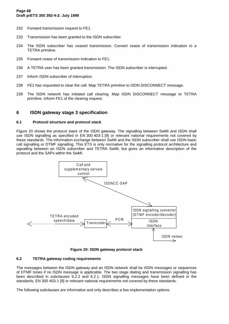
Page 68Draft prETS 300 392-4-2: July 1999
232 Forward transmission request to FE1.
233 Transmission has been granted to the ISDN subscriber.
234 The ISDN subscriber has ceased transmission. Convert cease of transmission indication to aTETRA primitive.
235 Forward cease of transmission indication to FE1.
236 A TETRA user has been granted transmission. The ISDN subscriber is interrupted.
237 Inform ISDN subscriber of interruption.
238 FE1 has requested to clear the call. Map TETRA primitive to ISDN DISCONNECT message.
239 The ISDN network has initiated call clearing. Map ISDN DISCONNECT message to TETRAprimitive. Inform FE1 of the clearing request.
6 ISDN gateway stage 3 specification
6.1 Protocol structure and protocol stack
Figure 20 shows the protocol stack of the ISDN gateway. The signalling between SwMI and ISDN shalluse ISDN signalling as specified in EN 300 403-1 [9] or relevant national requirements not covered bythese standards. The information exchange between SwMI and the ISDN subscriber shall use ISDN basiccall signalling or DTMF signalling. This ETS is only normative for the signalling protocol architecture andsignalling between an ISDN subscriber and TETRA SwMI, but gives an informative description of theprotocol and the SAPs within the SwMI.
ISDNCC-SAP
T ranscoderP C M ISDN
interface
ISDN signal l ing converter(D T M F encoder/decoder)
ISDN networ
C all andsupplem entary service
contro l
T E T R A encodedspeech /data
Figure 20: ISDN gateway protocol stack
6.2 TETRA gateway coding requirements
The messages between the ISDN gateway and an ISDN network shall be ISDN messages or sequencesof DTMF tones if no ISDN message is applicable. The two stage dialing and transmission signalling hasbeen described in subclauses 6.2.2 and 6.2.1. ISDN signalling messages have been defined in thestandards, EN 300 403-1 [9] or relevant national requirements not covered by these standards.
The following subclauses are informative and only describes a few implementation options.
Page 69Draft prETS 300 392-4-2: July 1999
6.2.1 Non end-to-end ISDN calls
When interworking has occurred with non ISDN networks, call set-up signalling information sent to theTETRA gateway is sent in-band when indicated by the progress indicator. The ISDN gateway shalltherefore follow call set-up procedures as described for the PSTN gateway ETS 300 392-4-1 [14] andEN 300 403-1 [9]. In addition the following call set-up guidance tones shall be supported.
6.2.1.1 Alert tone
See ISDN standards ETS 300 085 [10] or relevant national requirements not covered by this standard, forthe alert tone sent by the ISDN gateway.
See the TETRA standard ETS 300 392-4-1 [14], annex D for TETRA recommended guidance tones.
6.2.1.2 Busy tone
See ISDN standards ETS 300 085 [10] or relevant national requirements not covered by this standard, forthe busy tone sent by the ISDN gateway.
See the TETRA standard ETS 300 392-4-1 [14], annex D for TETRA recommended guidance tones.
6.2.1.3 Disconnect tone
See ISDN standards ETS 300 085 [10] or relevant national requirements not covered by this standard, forthe disconnect tone sent by the ISDN gateway.
See the TETRA standard ETS 300 392-4-1 [14], annex D for TETRA recommended guidance tones.
6.2.1.4 Invalid number tone
See ISDN standards ETS 300 085 [10] or relevant national requirements not covered by this standard, forthe invalid number tone sent by the ISDN gateway.
See the TETRA standard ETS 300 392-4-1 [14], annex D for TETRA recommended guidance tones.
6.2.2 Two stage dialling
6.2.2.1 Dialling Tone
See ISDN standards ETS 300 085 [10] or relevant national requirements not covered by this standard, forthe dialling tone sent by the ISDN gateway.
See the TETRA standard ETS 300 392-4-1 [14], annex D for TETRA recommended guidance tones.
6.2.2.2 Dialling
For incoming calls the second set of the two stage dialing consists of a sequence of DTMF digitsrepresenting the dialed TETRA user number. The ISDN subscriber shall use DTMF signalling for thesecond set of the two stage dialing either using a telephone set equipped with a DTMF generator or anyexternal DTMF generating device. The TETRA gateway shall receive the same DTMF tone and pauselengths as defined in I-ETS 300 245-1 [25] or relevant national requirement not covered by this standard.
If the complete ITSI or GTSI is not dialed, i.e. only the SSI, then the dialed number shall be ended with the# digit to indicate number complete.
6.2.2.3 Call set-up tones sent in-band
Call set-up signalling will occur in-band for two stage dialling. The guidance tones as described insubclause 6.2.1, ‘Non end-to-end ISDN calls’ shall therefore be supported.
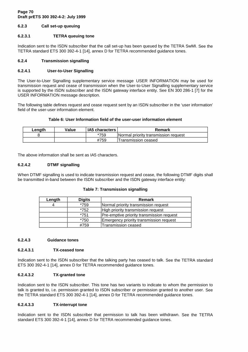
Page 70Draft prETS 300 392-4-2: July 1999
6.2.3 Call set-up queuing
6.2.3.1 TETRA queuing tone
Indication sent to the ISDN subscriber that the call set-up has been queued by the TETRA SwMI. See theTETRA standard ETS 300 392-4-1 [14], annex D for TETRA recommended guidance tones.
6.2.4 Transmission signalling
6.2.4.1 User-to-User Signalling
The User-to-User Signalling supplementary service message USER INFORMATION may be used fortransmission request and cease of transmission when the User-to-User Signalling supplementary serviceis supported by the ISDN subscriber and the ISDN gateway interface entity. See EN 300 286-1 [7] for theUSER INFORMATION message description.
The following table defines request and cease request sent by an ISDN subscriber in the ‘user information’field of the user-user information element.
Table 6: User Information field of the user-user information element
Length Value IA5 characters Remark8 *759 Normal priority transmission request
#759 Transmission ceased
The above information shall be sent as IA5 characters.
6.2.4.2 DTMF signalling
When DTMF signalling is used to indicate transmission request and cease, the following DTMF digits shallbe transmitted in-band between the ISDN subscriber and the ISDN gateway interface entity:
Table 7: Transmission signalling
Length Digits Remark4 *759 Normal priority transmission request
*752 High priority transmission request*751 Pre-emptive priority transmission request*750 Emergency priority transmission request#759 Transmission ceased
6.2.4.3 Guidance tones
6.2.4.3.1 TX-ceased tone
Indication sent to the ISDN subscriber that the talking party has ceased to talk. See the TETRA standardETS 300 392-4-1 [14], annex D for TETRA recommended guidance tones.
6.2.4.3.2 TX-granted tone
Indication sent to the ISDN subscriber. This tone has two variants to indicate to whom the permission totalk is granted to, i.e. permission granted to ISDN subscriber or permission granted to another user. Seethe TETRA standard ETS 300 392-4-1 [14], annex D for TETRA recommended guidance tones.
6.2.4.3.3 TX-interrupt tone
Indication sent to the ISDN subscriber that permission to talk has been withdrawn. See the TETRAstandard ETS 300 392-4-1 [14], annex D for TETRA recommended guidance tones.
Page 71Draft prETS 300 392-4-2: July 1999
6.2.5 DTMF signalling during ACTIVE state
6.2.5.1 From ISDN network
Any DTMF tones received from the ISDN network during the ACTIVE call state shall be mapped by theTETRA gateway interface entity into DTMF digits according to ETS 300 392-2 [12].
NOTE: See in I-ETS 300 245-1 [25] or relevant national requirement not covered by thisstandard for definition of DTMF tone and pause lengths.
6.2.5.2 From TETRA network
All DTMF digits sent from the TETRA call control application shall be mapped by the TETRA gatewayinterface entity into DTMF tones according to I-ETS 300 245-1 [25] or relevant national requirement notcovered by this standard.
NOTE: See in ETS 300 392-2 [12] for DTMF digit definitions.
6.3 TETRA gateway state definitions
ISDN state definitions for the users side defined in the standards, EN 300 403-1 [9] or relevant nationalrequirements not covered by these standards shall apply for the ISDN interface entity.
However, two extra states are needed when two stage dialing is performed. These states are theCOLLECT DIGITS state and the WAIT ANSWER state. From IDLE the ISDN gateway interface entity maygo to the COLLECT DIGITS state for incoming calls if it is determined that two stage dialing is needed.The state change occurs when sending the new dial tone in-band to the ISDN network.
The ISDN gateway interface entity shall remain in this state until all digits have been received. Uponcollection of all dialed digits, the ISDN gateway interface entity shall send a TETRA set-up request to theSwMI call control application and then go to state WAIT ANSWER.
Once the TETRA user or users have answered the call, the ISDN gateway interface entity shall proceed tostate ACTIVE.
6.4 TETRA gateway signalling procedures
The SDL representation showing the behaviour of the ISDN gateway interface entity is shown in figure A.1to A.7 of annex A.
6.4.1 Call set-up procedures
6.4.1.1 Incoming calls
Upon reception of the ISDN SETUP message the ISDN gateway interface entity shall perform incomingcall set-up procedures as described in the standards, EN 300 403-1 [9] or relevant national requirementsnot covered by these standards.
If the incoming call could be accepted by the ISDN gateway interface entity, a TETRA gateway SETUPprimitive shall be sent to the SwMI call control application for further call set-up procedures.
The called TETRA user or group may be indicated in the ISDN SETUP message either:
- by the ‘called party number’ information element of the ISDN SETUP message; or- by the ‘called party number’ and ‘called party subaddress’ information element of the ISDN SETUP
message.
If the ‘called party number’ information element in the ISDN SETUP message is not the external ISDNnumber for the TETRA ISDN gateway due to invocation of SS-DDI, then the ‘called party number’ shall bemapped into the ‘called external subscriber number’ of the TETRA gateway SETUP primitive when ISDNSS-DDI for incoming calls is supported.
Page 72Draft prETS 300 392-4-2: July 1999
When the ‘called party subaddress’ information element has been received in the ISDN SETUP messagedue to invocation of SS-SUB, then this element shall be mapped into the ‘called party address’ of theTETRA gateway SETUP primitive. This element shall be used by the SwMI call control application to routethe call to an individual or group and to determine which home network the individual or group belongs to.
If no ‘called party subaddress’ information element has been included in the ISDN SETUP message andthe ‘called party number’ information element message is the external ISDN number for the TETRA ISDNgateway, then two stage dialling shall be initiated.
6.4.1.1.1 Two stage dialling
To initiate two stage dialling the ISDN gateway interface entity shall send an ISDN CONNECT messagecontaining the progress indicator information element to the ISDN network when sufficient call set-upinformation has been received, i.e. response to en-bloc ISDN SETUP or completion of overlap receiving.The progress indicator information element shall be set to #1 ‘Call is not end-to-end ISDN; further callprogress information may be available’. A new dial tone shall then be sent in-band from the TETRAgateway interface entity towards the ISDN network.
The ISDN gateway interface entity shall receive the called party number in-band as DTMF digits from thecalling ISDN subscriber. The received DTMF digits shall be mapped into the ‘called party address’ of theTETRA gateway SETUP primitive.
NOTE: All following call set-up signalling will occur in-band.
6.4.1.1.2 Acknowledged group calls
An acknowledged group call initiated by the ISDN subscriber is not supported by this ETS.
6.4.1.1.3 Broadcast calls
A broadcast call initiated by the ISDN subscriber is not supported by this ETS.
6.4.1.1.4 Call priority
It may be possible for an ISDN subscriber to initiate priority calls by invoking the TETRA supplementaryservices Priority and Pre-emptive Priority call by employing the Service Code Command Format (SCCF)as described in ETS 300 738 [23] (See annex E for further information). However, supplementary servicesignalling interactions are outside the scope of this ETS.
It shall be an implementation matter which priority, if any, an incoming call from an ISDN subscriber shallreceive when TETRA SS-PC and TETRA SS-PPC is not supported by the ISDN gateway.
6.4.1.2 Outgoing calls
Upon reception of an TETRA gateway SETUP primitive from the SwMI call control application the ISDNgateway interface entity shall map the called external subscriber number into the ‘called party number’information element of the ISDN SETUP message. If available, the calling external subscriber number ofthe TETRA user or group shall be mapped into the ‘calling party number’ information element of the ISDNSETUP message otherwise the external number for the ISDN gateway shall be sent in the ‘calling partynumber’ information element.
Outgoing ISDN call set-up procedures shall then be performed as described in the standards,EN 300 403-1 [9] or relevant national requirements not covered by these standards.
The TETRA parameters simplex/duplex selection shall be used by the ISDN gateway interface entity todetermine whether transmission request, grant and cease procedures shall be active during the call.
6.4.1.2.1 Two stage dialling
Not applicable for outgoing calls.
Page 73Draft prETS 300 392-4-2: July 1999
6.4.1.2.2 Acknowledged group calls
An ISDN subscriber may participate in an acknowledged group call initiated by a TETRA user. The SwMIcall control application should consider the TETRA gateway COMPLETE or RELEASE primitive sent fromthe ISDN gateway interface entity as a polling response.
6.4.1.2.3 Broadcast calls
No indication has been standardized to that can be sent to the ISDN subscriber to indicate that abroadcast call has been initiated. Seen for the external subscriber, the call shall resemble a group call.However, it shall not be possible for the external subscriber to receive grant of transmission.
6.4.1.3 Colliding calls
Call collisions as such cannot occur at the TETRA gateway. Any simultaneous incoming or outgoing callsare dealt with separately and assigned different call references. See EN 300 403-1 [9] for further details.
6.4.1.4 Unsuccessful call set-up
Unsuccessful call set-up procedures at the ISDN gateway interface entity shall be performed according tothe standards, EN 300 403-1 [9] or relevant national requirements not covered by these standards.
6.4.2 Call maintenance procedures
When an individual call is set-up in a semi-duplex mode or a group call is active, transmission request andgranting shall be required. In the following subclauses three different methods for signalling transmissionrequest and responses through an ISDN gateway have been defined. One of the following methods maybe supported for transmission request and granting, e.g.:
- voice activity detection;- the supplementary service user-to-user information signalling; and- in-band signalling using DTMF signals.
NOTE 1: Simplex duplex selection is indicated in the TETRA gateway SETUP primitive foroutgoing calls and in the TETRA gateway COMPLETE primitive for incoming calls.
The parameters transmission request permission and transmission grant sent from the SwMI call controlapplication shall be used to indicate whether the ISDN subscriber may request for transmission (e.g. thiscould be a broadcast call and therefore the ISDN subscriber shall not receive transmission permission)and whether a transmission request has been granted or not.
In addition the following rules should be applied when an ISDN subscriber is participating in a semi-duplexindividual call or only one ISDN subscriber is participating in a group call.
To ensure that the ISDN subscriber can received transmission grant before starting to speak,transmission should always be granted to this user when no TETRA individual is transmitting. Therefore,when the SwMI call control application receives a TX CEASED PDU, it should always respond with a TXGRANTED PDU to either queued request from TETRA users or to the ISDN subscriber.
NOTE 2: Transmission should always be granted to requesting TETRA users before grantingtransmission to the ISDN subscriber.
If a TETRA user requests permission to transmit while the ISDN subscriber is transmitting, transmissionshould be interrupted towards the ISDN subscriber and transmission granted to the requesting TETRAuser.
Page 74Draft prETS 300 392-4-2: July 1999
6.4.2.1 Transmission request
6.4.2.1.1 Voice activity detection
A voice activity detector (VAD) may be used when an individual semi-duplex call exist between an ISDNsubscriber and a TETRA user.
NOTE 1: The connection between the ISDN subscriber, the ISDN network and the TETRA ISDNgateway is a duplex connection.
For group calls a VAD should only be used when group members are individually addressed through theISDN gateway.
NOTE 2: It is not recommended to use a VAD when group members are connected to the groupcall through a conference switch outside the TETRA ISDN gateway. This is due to thefact, that the ISDN gateway is considered a conference member in the externalconference switch and each member in the conference call are connected together ina duplex connection. Once transmission has been granted to an external groupmember the transmission grant will remain with the external group members as longas one of the them are speaking.
Upon voice activity detection from a external subscriber the ISDN gateway interface entity shall send aTETRA transmission request (TETRA gateway TX primitive) to the SwMI call control application,indicating which external subscriber has requested transmission.
6.4.2.1.2 User-to-user signalling
When the call is end-to-end ISDN the supplementary service user-to-user information may be used if theISDN subscriber(s) supports user-to-user signalling. User-to-user signalling service 3 shall then be usedby the external subscriber(s) when requesting transmission in a semi-duplex call with a TETRA user orgroup.
For outgoing call set-up request the user-to-user service 3 shall be requested during call set-up by theTETRA ISDN gateway interface entity. For incoming call set-up request the service may be requestedduring call set-up by the ISDN subscriber. However, if not requested by the calling ISDN subscriber, theISDN gateway interface entity shall invoke user-to-user service 3 after call set-up.
For group calls user-to-user signalling may be used when group members are individually addressedthrough the ISDN gateway or when group members are connected to the group call through a conferenceswitch outside the TETRA ISDN gateway.
NOTE 1: The location of an external conference switch is outside this standard and has notbeen standardized for TETRA inter-connect calls through an ISDN gateway.
NOTE 2: See EN 300 403-1 [9] and ETS 300 286-1 [7] for invocation procedures of thesupplementary service user-to-user signalling.
NOTE 3: See annex B for group call set-up sequences where the calling and called groupmembers are ISDN subscribers. User-to-user signalling service 3 is invoked for eachexternal member participating in the group call.
When an external ISDN subscriber requests transmission, the ISDN USER INFORMATION messageshall be sent to the ISDN gateway interface entity. For individual calls or individually addressed groupmembers the ISDN gateway interface entity shall indicate to the SwMI call control application whichexternal user has requested transmission.
The user information field of the user-to-user information element in the ISDN USER INFORMATIONmessage shall be set to transmission requested as defined in table 6. The protocol discriminator of theuser-to-user information element shall be set to IA5 characters.
Page 75Draft prETS 300 392-4-2: July 1999
6.4.2.1.3 DTMF signalling
When the call is not end-to-end ISDN or the ISDN subscriber does not support the supplementary serviceuser-to-user information, in-band signalling may be used to request transmission in a semi-duplex call. Aset of DTMF digits as defined in table 7 shall be sent to the TETRA ISDN gateway when an ISDNsubscriber request to transmit.
A DTMF decoder located at the TETRA ISDN gateway interface shall interpret the received DTMF digits.The ISDN gateway interface entity shall then send a TETRA transmission request (TETRA gateway TXprimitive) to the SwMI call control application, indicating which external subscriber has requestedtransmission.
For external group members connected to the TETRA ISDN gateway through a conference switch, nodistinction can be made between the subscribers connected to the conference. Transmission grantingshall occur to the external connection and not to an individual ISDN subscriber. Therefore, whentransmission has been granted to the external connection each subscriber connected to the conferenceswitch can transmit to TETRA group members.
NOTE 1: In contrary to voice activity detection, transmission will be ceased when the grantedsubscriber sends a DTMF digit indicating cease transmission regardless of whetherthe other subscribers connected to the conference switch are speaking.
NOTE 2: The location of an external conference switch is outside this standard and has notbeen standardized for TETRA inter-connect calls through an ISDN gateway.
DTMF signalling frequencies have been defined in I-ETS 300 245-1 [25].
6.4.2.2 Transmission request response
If permission to request for transmission is not given during call set-up, any transmission request receivedby the TETRA ISDN gateway interface entity from an ISDN subscriber shall be rejected, i.e. transmissionnot granted.
First upon reception of a TETRA gateway TX primitive sent from the SwMI call control applicationindicating that transmission may be requested, should the TETRA ISDN gateway interface entity sendtransmission request to the SwMI call control application.
A request to transmit from an ISDN subscriber may be queued. A queuing tone shall than be sent back tothe ISDN subscriber.
6.4.2.2.1 Voice activity detection
A TX granting tone as described in subclause 6.2.2.3.2 may be sent in-band to the requesting ISDNsubscriber. No other type of response shall be given to the requesting subscriber.
6.4.2.2.2 User-to-user signalling
The ISDN gateway interface entity shall inform the requesting ISDN subscriber of the transmissionresponse received from the SwMI call control application by sending a TX granting tone as described insubclause 6.2.2.3.2.
User-to-user signalling may be used by the ISDN gateway application to send further transmissioninformation to the ISDN subscriber, e.g. talking party identity. However, encoding of the user informationfield and presentation of such information to the ISDN subscriber is outside this standard.
6.4.2.2.3 DTMF signalling
The ISDN gateway interface entity shall inform the requesting ISDN subscriber of the transmissionresponse received from the SwMI call control application by sending a TX granting tone as described insubclause 6.2.2.3.2.
Page 76Draft prETS 300 392-4-2: July 1999
6.4.2.3 End of transmission
6.4.2.3.1 Voice activity detection
Transmission shall be ceased for the talking ISDN subscriber when no speech has been received for aminimum of 15 seconds.
A TX cease tone as described in subclause 6.2.2.3.1 may be sent in-band to the ISDN subscriber when aTETRA gateway TX primitive has been received from the SwMI call control application indicating that thetalking party has ceased to talk.
6.4.2.3.2 User-to-user signalling
When the talking ISDN subscriber wishes to cease transmission, the ISDN USER INFORMATIONmessage shall be sent to the ISDN gateway interface entity. For individual calls or individually addressedgroup members the ISDN gateway interface entity shall indicate to the SwMI call control application whichexternal user has ceased transmission.
The user information field of the user-to-user information element in the ISDN USER INFORMATIONmessage shall be set to transmission ceased as defined in table 6.
A TX cease tone as described in subclause 6.2.2.3.1 shall be sent in-band to the ISDN subscriber when aTETRA gateway TX primitive has been received from the SwMI call control application indicating that thetalking party has ceased to talk.
User-to-user signalling may be used by the ISDN gateway application to send further transmissioninformation to the ISDN subscriber, e.g. talking party identity. However, encoding of the user informationfield and presentation of such information to the ISDN subscriber is outside this standard.
6.4.2.3.3 DTMF signalling
A set of DTMF digits as defined in table 7 shall be sent to the TETRA ISDN gateway when the talkingISDN subscriber wishes to cease transmission.
A TX cease tone as described in subclause 6.2.2.3.1 shall be sent in-band to the ISDN subscriber when aTETRA gateway TX primitive has been received from the SwMI call control application indicating that thetalking party has ceased to talk.
6.4.2.4 Interruption of transmission
6.4.2.4.1 Voice activity detection
A TX interrupt tone as described in subclause 6.2.2.3.3 shall be sent in-band to the ISDN subscriber whena TETRA gateway TX primitive has been received from the SwMI call control application indicating thattransmission is to be withdrawn from the talking ISDN subscriber.
6.4.2.4.2 User-to-user signalling
A TX interrupt tone as described in subclause 6.2.2.3.3 shall be sent in-band to the ISDN subscriber whena TETRA gateway TX primitive has been received from the SwMI call control application indicating thattransmission is to be withdrawn from the talking ISDN subscriber.
User-to-user signalling may be used by the ISDN gateway application to send further transmissioninformation to the ISDN subscriber, e.g. talking party identity. However, encoding of the user informationfield and presentation of such information to the ISDN subscriber is outside this standard.
6.4.2.4.3 DTMF signalling
A TX interrupt tone as described in subclause 6.2.2.3.3 shall be sent in-band to the ISDN subscriber whena TETRA gateway TX primitive has been received from the SwMI call control application indicating thattransmission is to be withdrawn from the talking ISDN subscriber.
Page 77Draft prETS 300 392-4-2: July 1999
6.4.3 Call disconnection procedures
6.4.3.1 Disconnect initiated by TETRA user or TETRA SwMI
The ISDN gateway interface entity shall initiate ISDN disconnection procedures as described in thestandards, EN 300 403-1 [9] or relevant national requirements not covered by these standards whenrequested by the SwMI call control application.
The SwMI call control application shall be informed of release completion towards the ISDN network.
See annex D for mapping between TETRA and ISDN disconnect causes.
6.4.3.2 Disconnection initiated by ISDN subscriber
The ISDN gateway interface entity shall perform ISDN release procedures as described in the standards,EN 300 403-1 [9] or relevant national requirements not covered by these standards when a clearingmessage has been received by the ISDN network.
The SwMI call control application shall be informed of the release procedures towards the ISDN network.
See annex D for mapping between ISDN and TETRA disconnect causes.
6.4.3.3 Colliding disconnection
Subclause 5.3.5 in EN 300 403-1 [9] shall be applicable.
6.5 Protocol interaction between TETRA gateway and TETRA supplementary services
All protocol interactions with TETRA supplementary services are described in the individual TETRAsupplementary service standards.
6.6 Protocol interaction between TETRA gateway and ISDN supplementary services
All protocol interactions as identified in subclause 4.4 with ISDN supplementary services and othernetworks are described in the individual ISDN supplementary service standards.
6.7 TETRA gateway parameter values (timers)
ISDN timers for the users interface shall be defined as indicated in the standard ETS 300 403-1 [9] orrelevant national requirements not covered by these standards.
No extra TETRA timers are needed.
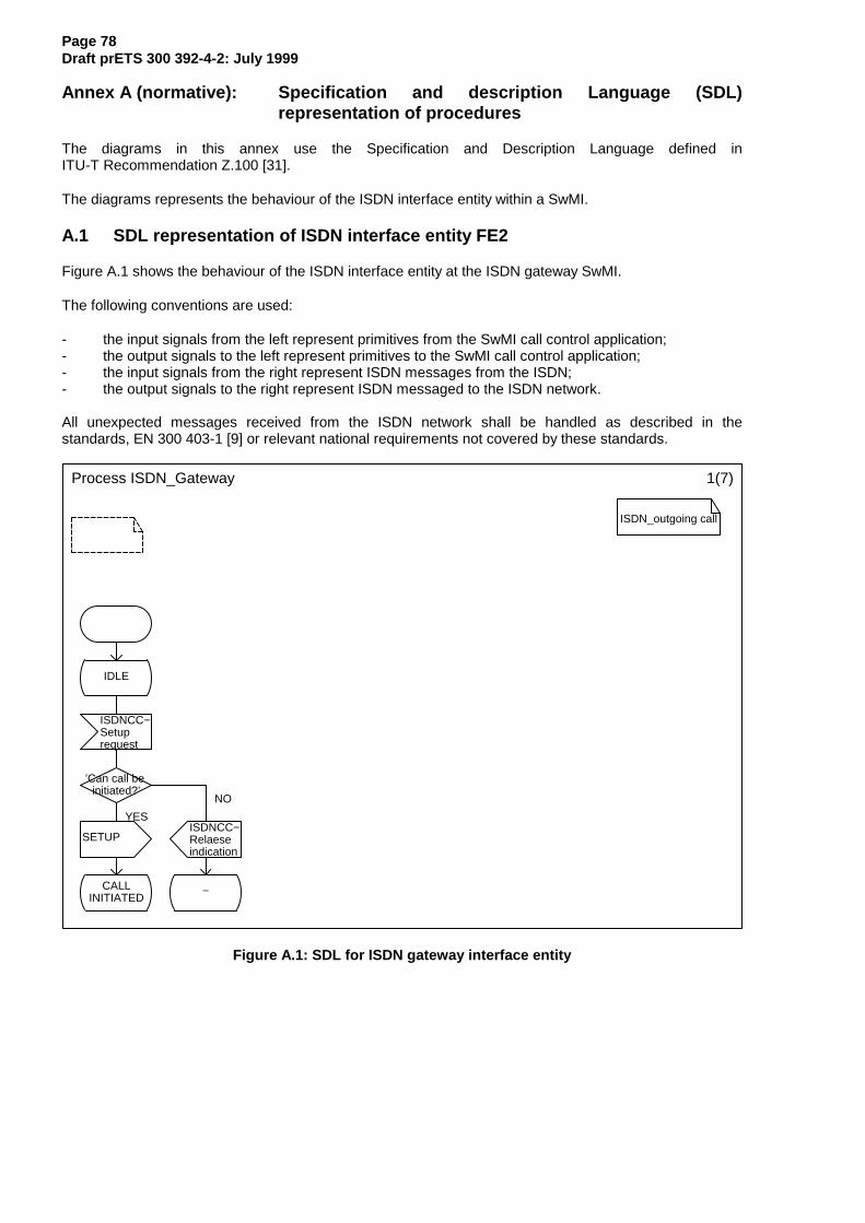
Page 78Draft prETS 300 392-4-2: July 1999
Annex A (normative): Specification and description Language (SDL)representation of procedures
The diagrams in this annex use the Specification and Description Language defined inITU-T Recommendation Z.100 [31].
The diagrams represents the behaviour of the ISDN interface entity within a SwMI.
A.1 SDL representation of ISDN interface entity FE2
Figure A.1 shows the behaviour of the ISDN interface entity at the ISDN gateway SwMI.
The following conventions are used:
- the input signals from the left represent primitives from the SwMI call control application;- the output signals to the left represent primitives to the SwMI call control application;- the input signals from the right represent ISDN messages from the ISDN;- the output signals to the right represent ISDN messaged to the ISDN network.
All unexpected messages received from the ISDN network shall be handled as described in thestandards, EN 300 403-1 [9] or relevant national requirements not covered by these standards.
Process ISDN_Gateway 1(7)
ISDN_outgoing call
IDLE
ISDNCC−Setuprequest
’Can call be initiated?’
SETUPISDNCC−Relaeseindication
CALLINITIATED
−
YES
NO
Figure A.1: SDL for ISDN gateway interface entity
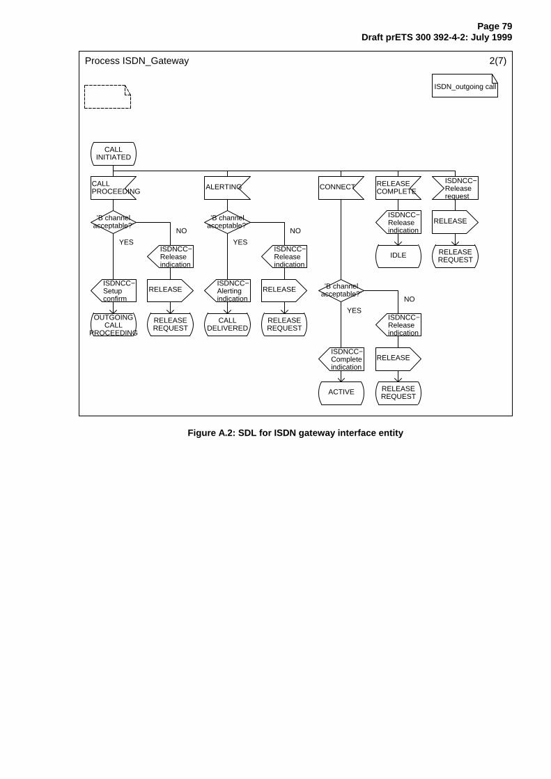
Page 79Draft prETS 300 392-4-2: July 1999
Process ISDN_Gateway 2(7)
ISDN_outgoing call
CALLINITIATED
CALL PROCEEDING
ALERTING CONNECT RELEASECOMPLETE
ISDNCC−Releaserequest
’B channelacceptable?’
’B channelacceptable?’
ISDNCC−Releaseindication
RELEASE
ISDNCC−Releaseindication
ISDNCC−Releaseindication
IDLE RELEASEREQUEST
ISDNCC−Setup confirm
RELEASEISDNCC−Alerting indication
RELEASE ’B channelacceptable?’
OUTGOINGCALL
PROCEEDING
RELEASEREQUEST
CALLDELIVERED
RELEASEREQUEST
ISDNCC−Releaseindication
ISDNCC−Complete indication
RELEASE
ACTIVE RELEASEREQUEST
NO
YES
NO
YES
NO
YES
Figure A.2: SDL for ISDN gateway interface entity
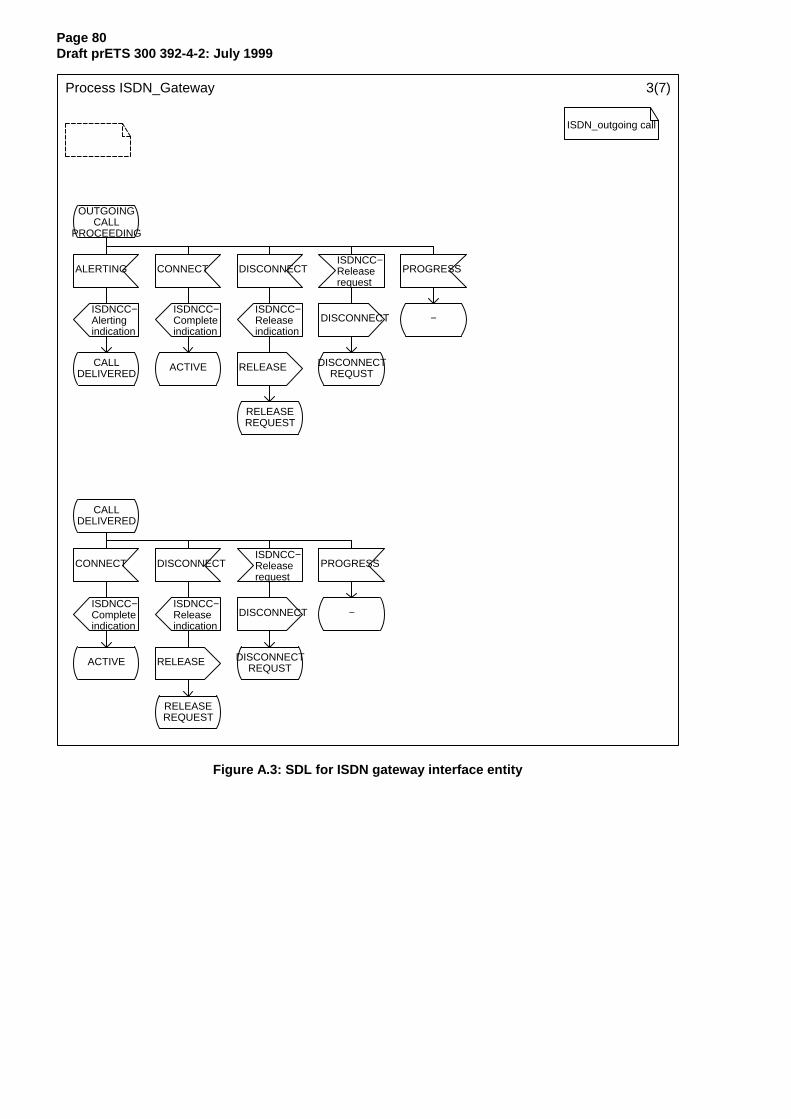
Page 80Draft prETS 300 392-4-2: July 1999
Process ISDN_Gateway 3(7)
ISDN_outgoing call
OUTGOINGCALL
PROCEEDING
ALERTING CONNECT DISCONNECTISDNCC−Releaserequest
PROGRESS
ISDNCC−Alerting indication
ISDNCC−Complete indication
ISDNCC−Releaseindication
DISCONNECT −
CALLDELIVERED
ACTIVE RELEASE DISCONNECTREQUST
RELEASEREQUEST
CALLDELIVERED
CONNECT DISCONNECTISDNCC−Releaserequest
PROGRESS
ISDNCC−Complete indication
ISDNCC−Releaseindication
DISCONNECT −
ACTIVE RELEASE DISCONNECTREQUST
RELEASEREQUEST
Figure A.3: SDL for ISDN gateway interface entity
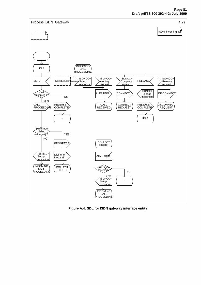
Page 81Draft prETS 300 392-4-2: July 1999
Process ISDN_Gateway 4(7)
ISDN_incoming call
IDLEINCOMING
CALLPROCEEDING
SETUP ’Call queued’ISDNCC−Setupresponse
ISDNCC−Alertingrequest
ISDNCC−Completerequest
RELEASEISDNCC−Releaserequest
’Callaccepted ?’
ALERTING CONNECTISDNCC−Releaseindication
DISCONNECT
CALL PROCEEDING
RELEASECOMPLETE
CALLRECEIVED
CONNECTREQUEST
RELEASE COMPLETE
DISCONNECTREQUEST
− IDLE
’Two stagedialing
necessary?’
PROGRESS COLLECTDIGITS
ISDNCC−Setupindication
Dial tonein−band
DTMF digits
INCOMINGCALL
PROCEEDING
COLLECTDIGITS
’All digitsreceived?’
ISDNCC−Setupindication
−
INCOMINGCALL
PROCEEDING
YES
NO
YES
NO
YES
NO
Figure A.4: SDL for ISDN gateway interface entity
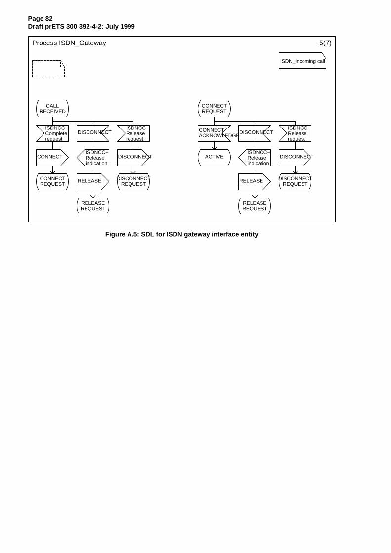
Page 82Draft prETS 300 392-4-2: July 1999
Process ISDN_Gateway 5(7)
ISDN_incoming call
CALLRECEIVED
ISDNCC−Completerequest
CONNECT
CONNECTREQUEST
DISCONNECT
ISDNCC−Releaseindication
RELEASE
RELEASEREQUEST
ISDNCC−Releaserequest
DISCONNECT
DISCONNECTREQUEST
CONNECTREQUEST
CONNECTACKNOWLEDGE
ACTIVE
DISCONNECT
ISDNCC−Releaseindication
RELEASE
RELEASEREQUEST
ISDNCC−Releaserequest
DISCONNECT
DISCONNECTREQUEST
Figure A.5: SDL for ISDN gateway interface entity
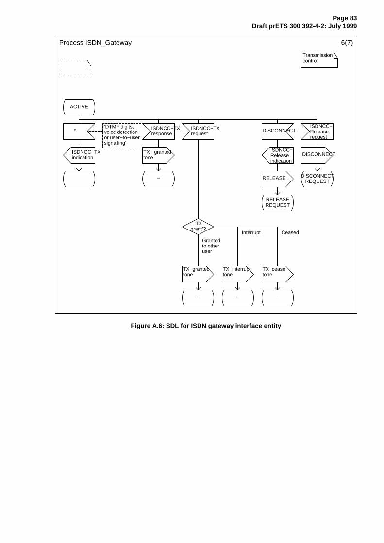
Page 83Draft prETS 300 392-4-2: July 1999
Process ISDN_Gateway 6(7)
Transmissioncontrol
ACTIVE
*’DTMF digits,voice detectionor user−to−usersignalling’
ISDNCC−TXresponse
ISDNCC−TXrequest
DISCONNECTISDNCC−Releaserequest
ISDNCC−TXindication
TX −grantedtone
ISDNCC−Releaseindication
DISCONNECT
− RELEASE DISCONNECTREQUEST
RELEASEREQUEST
’TXgrant’?
TX−grantedtone
TX−interrupttone
TX−ceasetone
− − −
Grantedto other user
Interrupt Ceased
Figure A.6: SDL for ISDN gateway interface entity
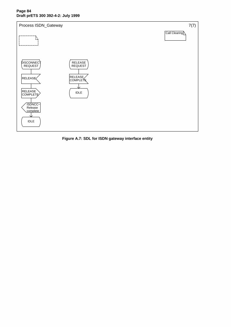
Page 84Draft prETS 300 392-4-2: July 1999
Process ISDN_Gateway 7(7)
Call Clearing
DISCONNECTREQUEST
RELEASEREQUEST
RELEASE RELEASECOMPLETE
RELEASECOMPLETE
IDLE
ISDNCC−Releasecomplete
IDLE
Figure A.7: SDL for ISDN gateway interface entity

Page 85Draft prETS 300 392-4-2: July 1999
Annex B (normative): TETRA group call set-up with external ISDN groupmembers
B.1 User-to-user signalling service 3
The following shows how a group call can be set-up when external group members are individuallyaddressed through the TETRA ISDN gateway.
The supplementary service user-to-user signalling has been invoked by the calling user during call set-up.User-to-user signalling service 3 (UUS3) is to be used for transmission requesting and granting.
The following requires that the ISDN subscribers and the TETRA ISDN gateway support the ISDNsupplementary services User-to-User signalling service 3 (UUS3).
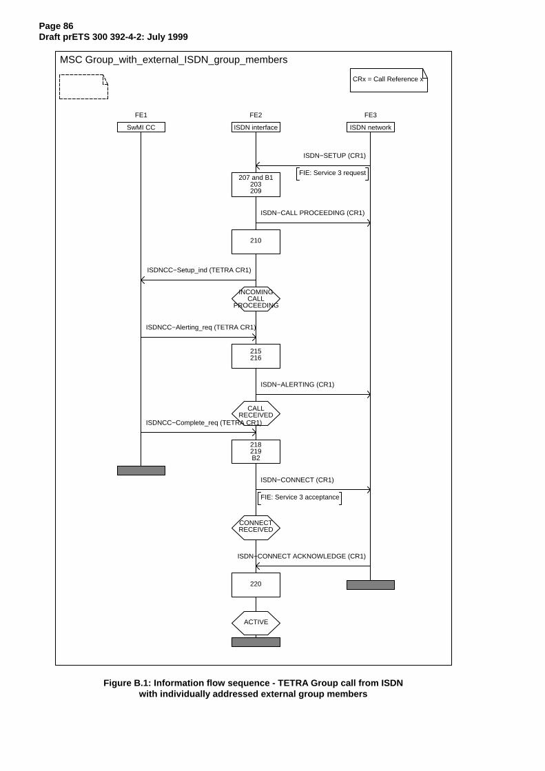
Page 86Draft prETS 300 392-4-2: July 1999
MSC Group_with_external_ISDN_group_members
FE1
SwMI CC
FE2
ISDN interface
FE3
ISDN network
ISDN−SETUP (CR1)
FIE: Service 3 request207 and B1
203209
ISDN−CALL PROCEEDING (CR1)
210
ISDNCC−Setup_ind (TETRA CR1)
INCOMINGCALL
PROCEEDING
ISDNCC−Alerting_req (TETRA CR1)
215216
ISDN−ALERTING (CR1)
CALLRECEIVED
ISDNCC−Complete_req (TETRA CR1)
218219B2
ISDN−CONNECT (CR1)
FIE: Service 3 acceptance
CONNECTRECEIVED
ISDN−CONNECT ACKNOWLEDGE (CR1)
220
ACTIVE
CRx = Call Reference x
Figure B.1: Information flow sequence - TETRA Group call from ISDNwith individually addressed external group members
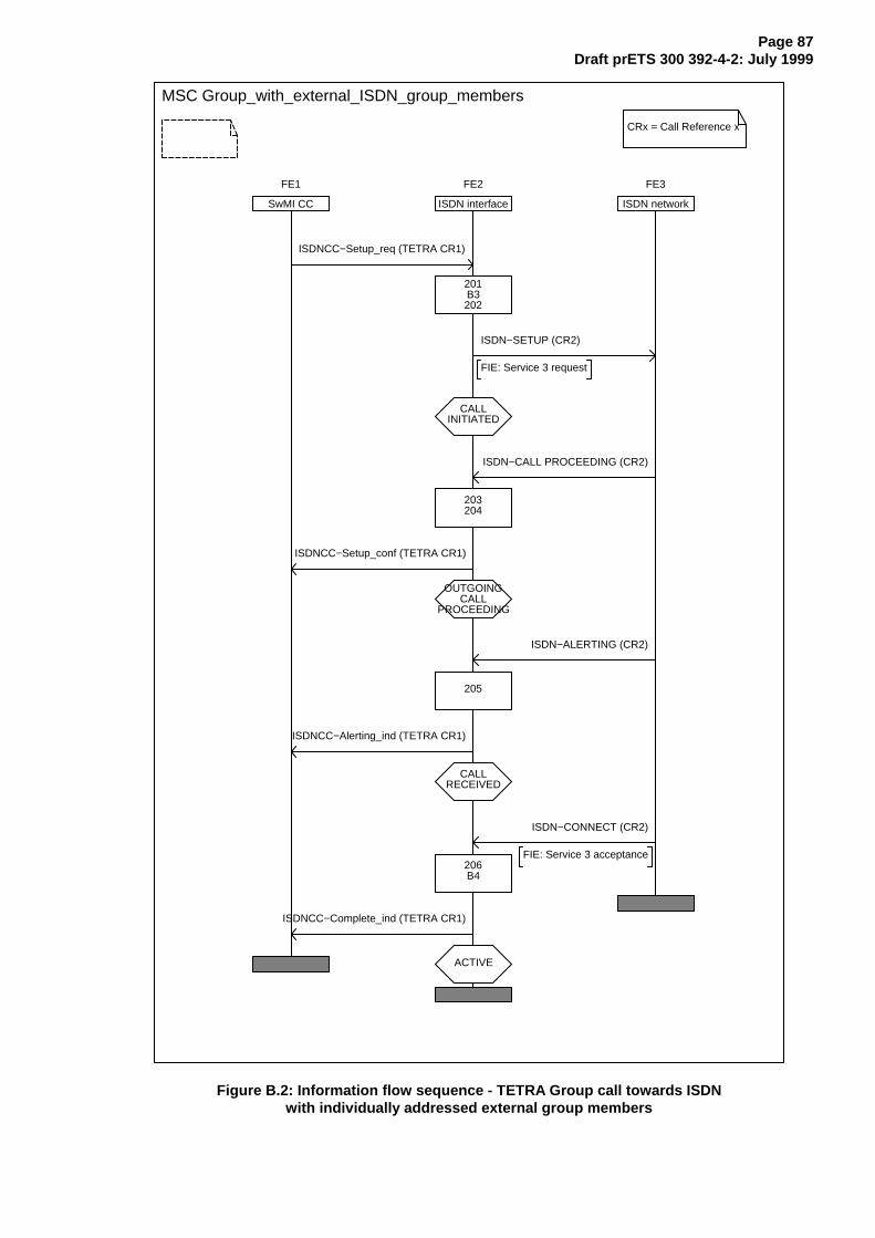
Page 87Draft prETS 300 392-4-2: July 1999
MSC Group_with_external_ISDN_group_members
FE1
SwMI CC
FE2
ISDN interface
FE3
ISDN network
ISDNCC−Setup_req (TETRA CR1)
201B3202
ISDN−SETUP (CR2)
FIE: Service 3 request
CALLINITIATED
ISDN−CALL PROCEEDING (CR2)
203204
ISDNCC−Setup_conf (TETRA CR1)
OUTGOINGCALL
PROCEEDING
ISDN−ALERTING (CR2)
205
ISDNCC−Alerting_ind (TETRA CR1)
CALLRECEIVED
ISDN−CONNECT (CR2)
FIE: Service 3 acceptance206B4
ISDNCC−Complete_ind (TETRA CR1)
ACTIVE
CRx = Call Reference x
Figure B.2: Information flow sequence - TETRA Group call towards ISDNwith individually addressed external group members

Page 88Draft prETS 300 392-4-2: July 1999
B.1.1 Functional Entity Actions (FEAs)
The following FE actions shall occur at the points indicated in the figures in annex B.
NOTE: In an individual call the controlling SwMI is collocated with the originating SwMI.
B.1.1.1 Functional entity actions of FE2
B1 The calling ISDN subscriber has requested user-to-user signalling service 3.B2 User-to-user signalling service 3 has been accepted by the ISDN gateway.B3 User-to-user signalling service 3 has been invoked by the ISDN gateway. Send a request for user-
to-user signalling service 3 in the ISDN-SETUP message to external group members.B4 User-to-user signalling service 3 has been accepted by the external group member.
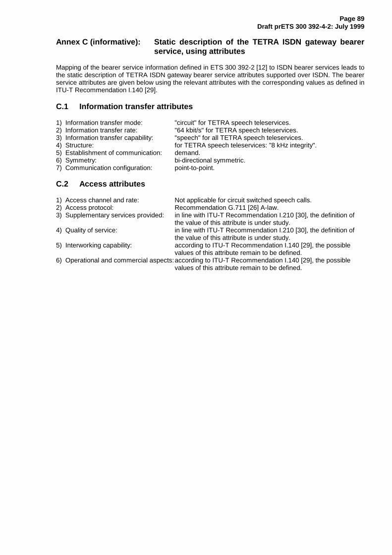
Page 89Draft prETS 300 392-4-2: July 1999
Annex C (informative): Static description of the TETRA ISDN gateway bearerservice, using attributes
Mapping of the bearer service information defined in ETS 300 392-2 [12] to ISDN bearer services leads tothe static description of TETRA ISDN gateway bearer service attributes supported over ISDN. The bearerservice attributes are given below using the relevant attributes with the corresponding values as defined inITU-T Recommendation I.140 [29].
C.1 Information transfer attributes
1) Information transfer mode: "circuit" for TETRA speech teleservices.2) Information transfer rate: "64 kbit/s" for TETRA speech teleservices.3) Information transfer capability: "speech" for all TETRA speech teleservices.4) Structure: for TETRA speech teleservices: "8 kHz integrity".5) Establishment of communication: demand.6) Symmetry: bi-directional symmetric.7) Communication configuration: point-to-point.
C.2 Access attributes
1) Access channel and rate: Not applicable for circuit switched speech calls.2) Access protocol: Recommendation G.711 [26] A-law.3) Supplementary services provided: in line with ITU-T Recommendation I.210 [30], the definition of
the value of this attribute is under study.4) Quality of service: in line with ITU-T Recommendation I.210 [30], the definition of
the value of this attribute is under study.5) Interworking capability: according to ITU-T Recommendation I.140 [29], the possible
values of this attribute remain to be defined.6) Operational and commercial aspects:according to ITU-T Recommendation I.140 [29], the possible
values of this attribute remain to be defined.
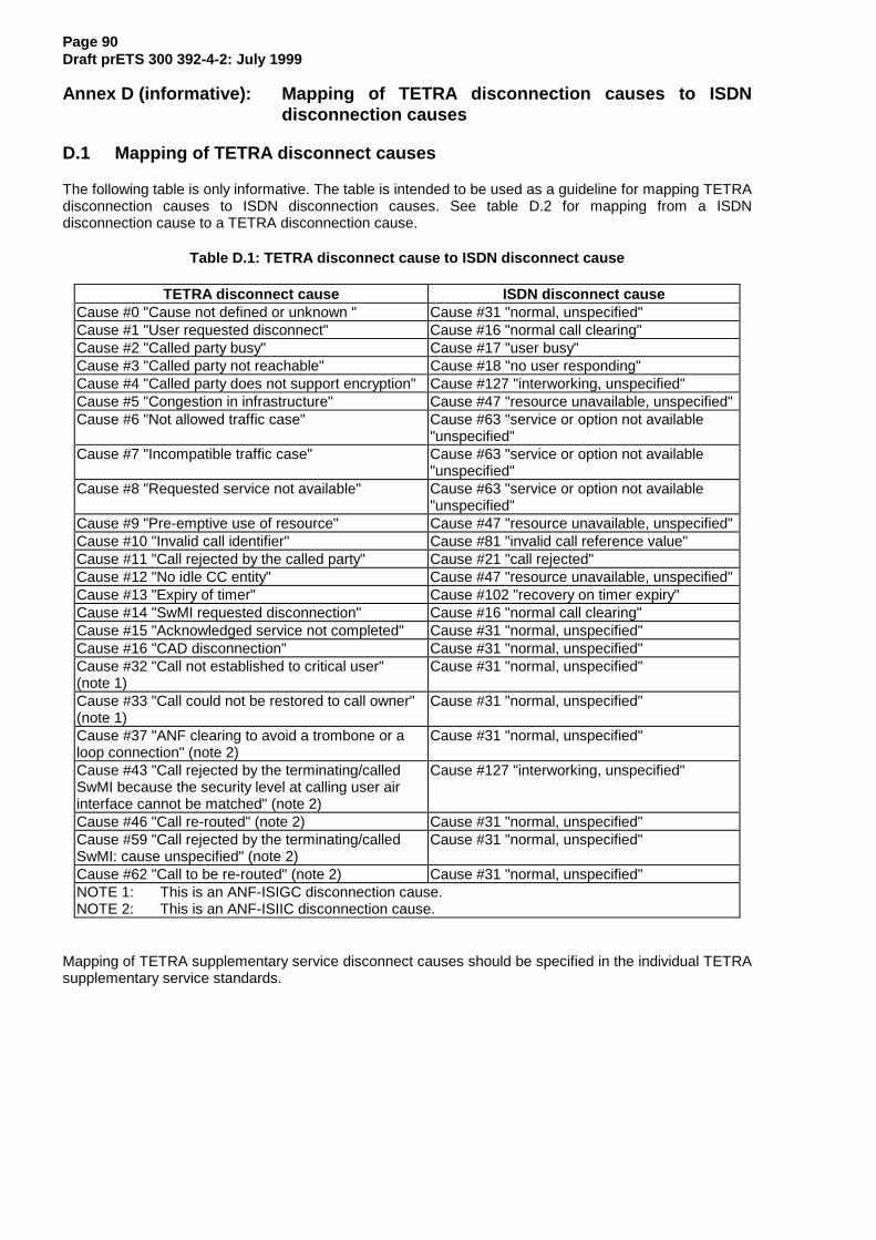
Page 90Draft prETS 300 392-4-2: July 1999
Annex D (informative): Mapping of TETRA disconnection causes to ISDNdisconnection causes
D.1 Mapping of TETRA disconnect causes
The following table is only informative. The table is intended to be used as a guideline for mapping TETRAdisconnection causes to ISDN disconnection causes. See table D.2 for mapping from a ISDNdisconnection cause to a TETRA disconnection cause.
Table D.1: TETRA disconnect cause to ISDN disconnect cause
TETRA disconnect cause ISDN disconnect causeCause #0 "Cause not defined or unknown " Cause #31 "normal, unspecified"Cause #1 "User requested disconnect" Cause #16 "normal call clearing"Cause #2 "Called party busy" Cause #17 "user busy"Cause #3 "Called party not reachable" Cause #18 "no user responding"Cause #4 "Called party does not support encryption" Cause #127 "interworking, unspecified"Cause #5 "Congestion in infrastructure" Cause #47 "resource unavailable, unspecified"Cause #6 "Not allowed traffic case" Cause #63 "service or option not available
"unspecified"Cause #7 "Incompatible traffic case" Cause #63 "service or option not available
"unspecified"Cause #8 "Requested service not available" Cause #63 "service or option not available
"unspecified"Cause #9 "Pre-emptive use of resource" Cause #47 "resource unavailable, unspecified"Cause #10 "Invalid call identifier" Cause #81 "invalid call reference value"Cause #11 "Call rejected by the called party" Cause #21 "call rejected"Cause #12 "No idle CC entity" Cause #47 "resource unavailable, unspecified"Cause #13 "Expiry of timer" Cause #102 "recovery on timer expiry"Cause #14 "SwMI requested disconnection" Cause #16 "normal call clearing"Cause #15 "Acknowledged service not completed" Cause #31 "normal, unspecified"Cause #16 "CAD disconnection" Cause #31 "normal, unspecified"Cause #32 "Call not established to critical user"(note 1)
Cause #31 "normal, unspecified"
Cause #33 "Call could not be restored to call owner"(note 1)
Cause #31 "normal, unspecified"
Cause #37 "ANF clearing to avoid a trombone or aloop connection" (note 2)
Cause #31 "normal, unspecified"
Cause #43 "Call rejected by the terminating/calledSwMI because the security level at calling user airinterface cannot be matched" (note 2)
Cause #127 "interworking, unspecified"
Cause #46 "Call re-routed" (note 2) Cause #31 "normal, unspecified"Cause #59 "Call rejected by the terminating/calledSwMI: cause unspecified" (note 2)
Cause #31 "normal, unspecified"
Cause #62 "Call to be re-routed" (note 2) Cause #31 "normal, unspecified"NOTE 1: This is an ANF-ISIGC disconnection cause.NOTE 2: This is an ANF-ISIIC disconnection cause.
Mapping of TETRA supplementary service disconnect causes should be specified in the individual TETRAsupplementary service standards.
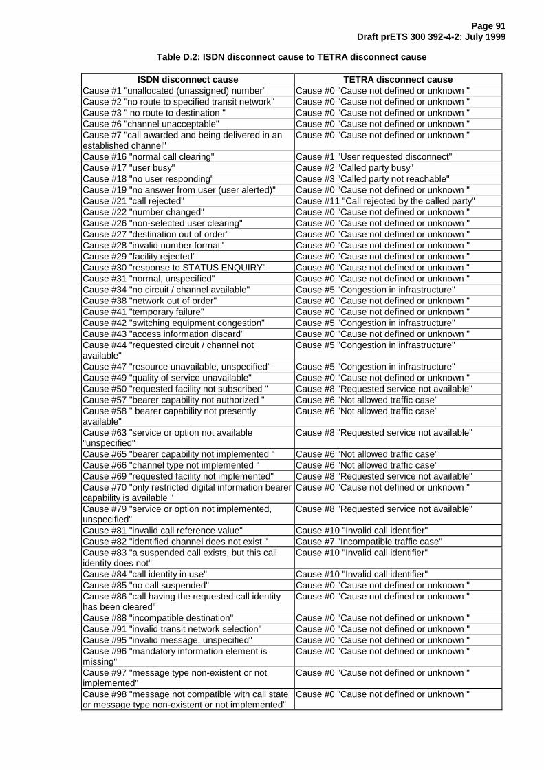
Page 91Draft prETS 300 392-4-2: July 1999
Table D.2: ISDN disconnect cause to TETRA disconnect cause
ISDN disconnect cause TETRA disconnect causeCause #1 "unallocated (unassigned) number" Cause #0 "Cause not defined or unknown "Cause #2 "no route to specified transit network" Cause #0 "Cause not defined or unknown "Cause #3 " no route to destination " Cause #0 "Cause not defined or unknown "Cause #6 "channel unacceptable" Cause #0 "Cause not defined or unknown "Cause #7 "call awarded and being delivered in anestablished channel"
Cause #0 "Cause not defined or unknown "
Cause #16 "normal call clearing" Cause #1 "User requested disconnect"Cause #17 "user busy" Cause #2 "Called party busy"Cause #18 "no user responding" Cause #3 "Called party not reachable"Cause #19 "no answer from user (user alerted)" Cause #0 "Cause not defined or unknown "Cause #21 "call rejected" Cause #11 "Call rejected by the called party"Cause #22 "number changed" Cause #0 "Cause not defined or unknown "Cause #26 "non-selected user clearing" Cause #0 "Cause not defined or unknown "Cause #27 "destination out of order" Cause #0 "Cause not defined or unknown "Cause #28 "invalid number format" Cause #0 "Cause not defined or unknown "Cause #29 "facility rejected" Cause #0 "Cause not defined or unknown "Cause #30 "response to STATUS ENQUIRY" Cause #0 "Cause not defined or unknown "Cause #31 "normal, unspecified" Cause #0 "Cause not defined or unknown "Cause #34 "no circuit / channel available" Cause #5 "Congestion in infrastructure"Cause #38 "network out of order" Cause #0 "Cause not defined or unknown "Cause #41 "temporary failure" Cause #0 "Cause not defined or unknown "Cause #42 "switching equipment congestion" Cause #5 "Congestion in infrastructure"Cause #43 "access information discard" Cause #0 "Cause not defined or unknown "Cause #44 "requested circuit / channel notavailable"
Cause #5 "Congestion in infrastructure"
Cause #47 "resource unavailable, unspecified" Cause #5 "Congestion in infrastructure"Cause #49 "quality of service unavailable" Cause #0 "Cause not defined or unknown "Cause #50 "requested facility not subscribed " Cause #8 "Requested service not available"Cause #57 "bearer capability not authorized " Cause #6 "Not allowed traffic case"Cause #58 " bearer capability not presentlyavailable"
Cause #6 "Not allowed traffic case"
Cause #63 "service or option not available"unspecified"
Cause #8 "Requested service not available"
Cause #65 "bearer capability not implemented " Cause #6 "Not allowed traffic case"Cause #66 "channel type not implemented " Cause #6 "Not allowed traffic case"Cause #69 "requested facility not implemented" Cause #8 "Requested service not available"Cause #70 "only restricted digital information bearercapability is available "
Cause #0 "Cause not defined or unknown "
Cause #79 "service or option not implemented,unspecified"
Cause #8 "Requested service not available"
Cause #81 "invalid call reference value" Cause #10 "Invalid call identifier"Cause #82 "identified channel does not exist " Cause #7 "Incompatible traffic case"Cause #83 "a suspended call exists, but this callidentity does not"
Cause #10 "Invalid call identifier"
Cause #84 "call identity in use" Cause #10 "Invalid call identifier"Cause #85 "no call suspended" Cause #0 "Cause not defined or unknown "Cause #86 "call having the requested call identityhas been cleared"
Cause #0 "Cause not defined or unknown "
Cause #88 "incompatible destination" Cause #0 "Cause not defined or unknown "Cause #91 "invalid transit network selection" Cause #0 "Cause not defined or unknown "Cause #95 "invalid message, unspecified" Cause #0 "Cause not defined or unknown "Cause #96 "mandatory information element ismissing"
Cause #0 "Cause not defined or unknown "
Cause #97 "message type non-existent or notimplemented"
Cause #0 "Cause not defined or unknown "
Cause #98 "message not compatible with call stateor message type non-existent or not implemented"
Cause #0 "Cause not defined or unknown "

Page 92Draft prETS 300 392-4-2: July 1999
ISDN disconnect cause TETRA disconnect causeCause #99 "information element non-existent or notimplemented"
Cause #0 "Cause not defined or unknown "
Cause #100 "invalid information element contents" Cause #0 "Cause not defined or unknown "Cause #101 "message not compatible with callstate"
Cause #0 "Cause not defined or unknown "
Cause #102 "recovery on timer expiry" Cause #13 "Expiry of timer"Cause #111 "protocol error, unspecified" Cause #0 "Cause not defined or unknown "Cause #127 "interworking, unspecified" Cause #0 "Cause not defined or unknown "
For any other ISDN disconnection causes, the TETRA disconnect cause #0 " Cause not defined orunknown " should be used.
Page 93Draft prETS 300 392-4-2: July 1999
Annex E (informative): TETRA supplementary services
E.1 TETRA supplementary services - SCCF
In order to control and gain access to the TETRA supplementary services it is envisaged that the ISDNsubscriber employs the Service Code Command Format (SCCF) as described in ETS 300 738 [23].
Supplementary services are invoked by entering star-hash combinations and digits as defined in table 1and in annex A of ETS 300 738 [23].
The Service Code Command (SCC) used by the ISDN subscriber to gain access to, and control of,TETRA supplementary services should have the following syntax:
"PX SC (SR SI) SX FINISH"
Where:
- PX is a mandatory service prefix;- SC is a mandatory service code;- SR is one or more separator/s, as required;- SI is one or more unit of supplementary information, as required;- SX is a service suffix, as required;- FINISH is a finish command, when applicable.
NOTE 1: The SX service suffix is normally required as the FINISH command applicable only inthe form of "on-hook", when the ISDN subscriber disconnects the ISDN call whilecompleting a TETRA supplementary service request.
Where units of supplementary information are required, each unit of supplementary information should bepreceded by a separator. The number of supplementary information units that can be included within asingle command sequence is at the discretion of the terminal, network, or service provider.
NOTE 2: Services which require more than two supplementary information units may be bettersupported by the interactive dialogue format, see ETS 300 738 [23], subclause 6.2.
The switching order invocation of TETRA supplementary services as defined in ETS 300 738 [23],subclause 6.1.2.1 is not applicable as it would interact with the ISDN supplementary services.
The abbreviated dialing command for access to an abbreviated dialing service to dial TETRA identitieswhere a TETRA user identity is stored within the ISDN gateway should have the following syntax:
"AN SX"
Where:
- AN is a mandatory abbreviated number; and- SX is a mandatory service suffix.
Refer to ETS 300 738 [23], subclause 6.1.3 for further details.

Page 94Draft prETS 300 392-4-2: July 1999
Annex F (informative): Bibliography
- ETS 300 064-1: "Integrated Services Digital Network (ISDN); Direct Dialling In (DDI)supplementary service; Digital Subscriber Signalling System No. one (DSS1) protocol; Part 1:Protocol specification".
- ETS 300 061-1: "Integrated Services Digital Network (ISDN); Subaddressing (SUB)supplementary service; Digital Subscriber Signalling System No. one (DSS1) protocol; Part 1:Protocol specification".
- ETS 300 195-1: "Integrated Services Digital Network (ISDN); Supplementary service interactions;Digital Subscriber Signalling System No. one (DSS1) protocol; Part 1: Protocol specification".

Page 95Draft prETS 300 392-4-2: July 1999
History
Document history
July 1999 Public Enquiry PE 9952: 1999-07-28 to 1999-11-26