Embed Size (px)
Citation preview
Draft 0.1 P802.17
Draft Standard forInformation Technology -Telecommunicationsand information exchange between systems -Local and metropolitan area networks -Specific requirements -Resilient Packet Ring Access Method &Physical Layer Specifications
Draft 0.1October 9, 2001
SponsorComputer Society, LAN/MAN Standards Committee
Abstract: A set of protocols for transfering packets over physical and logical ring topologies isspecified. The primary application area is for metropolitian area networks (MANs), but the proto-cols are applicable to other environments with full-duplex point-to-point cable connections.Keywords: resilient ring protocol, MAN
Copyright © 2000 by the Institute of Electrical and Electronics Engineers, Inc.345 East 47th StreetNew York, NY 10017, USAAll rights reserved.
This is an unapproved draft of a proposed IEEE Standard, subject to change. Permission is hereby grantedfor IEEE Standards Committee participants to reproduce this document for purposes of IEEEstandardization activities. If this document is to be submitted to ISO or IEC, notification shall be given to theIEEE Copyright Administrator. Permission is also granted for member bodies and technical committees ofISO and IEC to reproduce this document for purposes of developing a national position. Other entitiesseeking permission to reproduce this document for standardization or other activities, or to reproduceportions of this document for these or other uses must contact the IEEE Standards Department for theappropriate license. Use of information contained in this unapproved draft is at your own risk.
IEEE Standards DepartmentCopyright and Permissions445 Hoes Lane, P.O. Box 1331Piscataway, NJ 08855-1331 USA
IEEE Standards documents are developed within the Technical Committees of the IEEE Soci-eties and the Standards Coordinating Committees of the IEEE Standards Board. Members of thecommittees serve voluntarily and without compensation. They are not necessarily members ofthe Institute. The standards developed within IEEE represent a consensus of the broad expertiseon the subject within the Institute as well as those activities outside of IEEE that have expressedan interest in participating in the development of the standard.
Use of an IEEE Standard is wholly voluntary. The existence of an IEEE Standard does not implythat there are no other ways to produce, test, measure, purchase, market, or provide other goodsand services related to the scope of the IEEE Standard. Furthermore, the viewpoint expressed atthe time a standard is approved and issued is subject to change brought about through develop-ments in the state of the art and comments received from users of the standard. Every IEEEStandard is subjected to review at least every five years for revision or reaffirmation. When adocument is more than five years old and has not been reaffirmed, it is reasonable to concludethat its contents, although still of some value, do not wholly reflect the present state of the art.Users are cautioned to check to determine that they have the latest edition of any IEEE Standard.
Comments for revision of IEEE Standards are welcome from any interested party, regardless ofmembership affiliation with IEEE. Suggestions for changes in documents should be in the formof a proposed change of text, together with appropriate supporting comments.
Interpretations: Occasionally questions may arise regarding the meaning of portions of standardsas they relate to specific applications. When the need for interpretations is brought to the atten-tion of IEEE, the Institute will initiate action to prepare appropriate responses. Since IEEE Stan-dards represent a consensus of all concerned interests, it is important to ensure that anyinterpretation has also received the concurrence of a balance of interests. For this reason IEEEand the members of its technical committees are not able to provide an instant response to inter-pretation requests except in those cases where the matter has previously received formalconsideration.
Comments on standards and requests for interpretations should be addressed to:
Secretary, IEEE Standards Board445 Hoes LaneP.O. Box 1331Piscataway, NJ 08855-1331USA
IEEE Standards documents are adopted by the Institute of Electrical and ElectronicsEngineers without regard to whether their adoption may involve patents on articles,materials, or processes. Such adoption does not assume any liability to any patentowner, nor does it assume any obligation whatever to parties adopting the standardsdocuments.
2
Patent Statement
The developers of this standard have requested that holder’s of patents, that may be required for theimplementation of the standard, disclose such patents to the publisher. However, neither the developers northe publisher have undertaken a patent search in order to identify which, if any, patents may apply to thisstandard.
No position is taken with respect to the validity of any claim or any patent rights that may have beendisclosed. Details of submitted statements may be obtained from the publisher concerning any statement ofpatents and willingness to grant a license under these rights on reasonable and nondiscriminatory terms andconditions to applicants desiring to obtain such a license.
Introduction
Comments on this document or questions on the Working Group status should be addressed to the WorkingGroup Chair:
Mike TakefmanCisco Systems, Inc.
365 March RoadKanata, Ontario
Canada K2K 2C9Phone: +1.613.271.3399FAX: +1.613.271.3333Email: [email protected]
Comments on this proposal can be directed to the contributing editors:
Necdet Uzun, Carey Kloss & Jim KaoCisco Systems Inc
170 W. Tasman Dr.San Jose, CA 95134
Email: [email protected]@cisco.com, [email protected]
3

4
9/7/01 Draft ProposalRESILIENT PACKET RING (RPR) P802.17
Contents
1. Overview.............................................................................................................................................. 9
1.1 Document scope and purpose ...................................................................................................... 9
2. Terms and Taxonomy ........................................................................................................................ 10
2.1 Ring Terminology...................................................................................................................... 102.2 Spatial Reuse.............................................................................................................................. 102.3 Fairness ...................................................................................................................................... 112.4 Transit Buffer............................................................................................................................. 11
3. RPR Overview ................................................................................................................................... 12
3.1 Receive Operation Overview..................................................................................................... 123.2 Transmit Operation Overview ................................................................................................... 123.3 RPR Fairness Algorithm (RPR-fa) Overview .......................................................................... 12
3.3.1 Inter operability between single/dual transit buffer fairness schemes ............................ 133.3.2 MAC client interface considerations............................................................................... 13
3.4 Intelligent Protection Switching (IPS) Protocol Overview........................................................ 133.4.1 Wrap Protection .............................................................................................................. 133.4.2 Steering Protection.......................................................................................................... 16
4. Packet Formats................................................................................................................................... 17
4.1 Overall Packet Format ............................................................................................................... 174.1.1 Customer Seperation ID.................................................................................................. 174.1.2 FCS.................................................................................................................................. 17
4.2 Generic Packet Header Format .................................................................................................. 184.2.1 Time To Live (TTL) ....................................................................................................... 184.2.2 Mode FIeld...................................................................................................................... 184.2.3 Wrap Bit.......................................................................................................................... 194.2.4 Priority Field (PRI) ......................................................................................................... 194.2.5 Steer Bit (P-bit) ............................................................................................................... 194.2.6 HEC Field ....................................................................................................................... 194.2.7 Destination Address ........................................................................................................ 194.2.8 Source Address ............................................................................................................... 194.2.9 Protocol Type.................................................................................................................. 19
4.3 RPR Usage Packet Format......................................................................................................... 204.4 RPR Control Packet Format ..................................................................................................... 20
4.4.1 Control Ver ..................................................................................................................... 214.4.2 Control Type ................................................................................................................... 214.4.3 Control TTL .................................................................................................................... 224.4.4 Control Checksum........................................................................................................... 224.4.5 Payload............................................................................................................................ 224.4.6 Addressing ...................................................................................................................... 22
4.5 Ring Indentifier Discovery ........................................................................................................ 224.5.1 Ring Identifier Discovery State....................................................................................... 23
4.5.1.1 Init Mode ............................................................................................................ 234.5.1.2 Active Query Mode ............................................................................................ 234.5.1.3 Passive Listen Mode........................................................................................... 234.5.1.4 Discovered Mode................................................................................................ 23
5
9/7/01 Draft ProposalRESILIENT PACKET RING (RPR) P802.17
4.5.2 Ring ID Discovery Rule.................................................................................................. 234.5.3 Ring ID Discovery State Transition................................................................................ 244.5.4 Ring ID Discovery Packet Format .................................................................................. 264.5.5 Ring ID Octet .................................................................................................................. 26
4.6 Topology Discovery .................................................................................................................. 264.6.1 Topology Length............................................................................................................. 284.6.2 Topology Originator ....................................................................................................... 284.6.3 MAC bindings................................................................................................................. 284.6.4 MAC Type Format.......................................................................................................... 28
4.7 Intelligent Protection Switching (IPS)....................................................................................... 294.7.1 Destination MAC Address .............................................................................................. 294.7.2 Source MAC Address ..................................................................................................... 294.7.3 IPS Octet ......................................................................................................................... 29
4.8 Circulating packet detection (stripping) .................................................................................... 30
5. Packet acceptance and stripping ........................................................................................................ 31
5.1 Transmission and forwarding with priority ............................................................................... 325.2 Wrapping of Data....................................................................................................................... 33
6. Fairness Algorithms ........................................................................................................................... 34
6.1 Basic RPR-fa Rules Of Operation ............................................................................................. 346.2 Multi-Choke RPR-fa.................................................................................................................. 346.3 RPR-fa pseudo-code ................................................................................................................. 356.4 Threshold settings ...................................................................................................................... 37
7. RPR Synchronization........................................................................................................................ 38
8. IPS Protocol Description ................................................................................................................... 39
8.1 The IPS Request Types.............................................................................................................. 398.2 The IPS Path Indicator............................................................................................................... 408.3 RPR IPS Protocol States ........................................................................................................... 40
8.3.1 Idle .................................................................................................................................. 408.3.2 Wrapped .......................................................................................................................... 40
8.4 IPS Protocol Rules ..................................................................................................................... 408.4.1 RPR IPS Packet Transfer Mechanism ........................................................................... 408.4.2 RPR IPS Signaling and Wrapping Mechanism.............................................................. 408.4.3 Example .......................................................................................................................... 41
8.5 RPR IPS Protocol Rules ........................................................................................................... 428.6 State Transitions ........................................................................................................................ 438.7 Failure Examples ....................................................................................................................... 44
8.7.1 Signal Failure - Single Fiber Cut Scenario ..................................................................... 448.7.1.1 Signal Fail Scenario............................................................................................ 458.7.1.2 Signal Fail Clears................................................................................................ 45
8.7.2 Signal Failure - Bidirectional Fiber Cut Scenario........................................................... 468.7.2.1 Signal Fail Scenario............................................................................................ 468.7.2.2 Signal Fail Clears................................................................................................ 47
8.7.3 Failed Node Scenario ...................................................................................................... 478.7.3.1 Node Failure (or fiber cuts on both sides of the node) ....................................... 488.7.3.2 Failed Node and One Span Return to Service .................................................... 488.7.3.3 Second Span Returns to Service ......................................................................... 488.7.3.4 Bidirectional Fiber Cut ....................................................................................... 49
6
9/7/01 Draft ProposalRESILIENT PACKET RING (RPR) P802.17
8.7.3.5 Node C is Powered Up and Fibers Between Nodes A and C are Reconnected.. 498.7.3.6 Second Span Put Into Service............................................................................. 50
9. Physical Media................................................................................................................................... 51
9.1 SONET/SDH Network .............................................................................................................. 519.1.1 POS Framing................................................................................................................... 519.1.2 GFP Framing................................................................................................................... 51
9.2 Ethernet ...................................................................................................................................... 51
10. Pass-thru mode................................................................................................................................... 52
11. References.......................................................................................................................................... 53
7

Cisco Proposal 9/7/01P802.17 RESILIENT PACKET RING (RPR)
8

Proposals forResilient Packet Ring (RPR)
1. Overview
This document specifies the RPR MAC layer protocol for use with ring based media.
The primary requirements for RPR are as follows:
- Efficient use of bandwidth due to spatial reuse and minimal protocol overhead- Support for 3 traffic priorities- Scalability across a large number of stations attached to a ring- "Plug and play" design without a software based station management transfer (SMT) protocol or
ring master negotiation as seen in other ring based MAC protocols [1][2]- Weighted Fairness among nodes using the ring (Each station can be assigned a proportion of the
ring bandwidth).- Support for ring based redundancy (error detection, ring wrap, etc.) similar to that found in SONET
BLSR specifications.- Independence of physical layer (layer 1) media type.
This document defines the terminology used with RPR, packet formats, the protocol format, protocol opera-tion and associated protocol finite state machines.
1.1 Document scope and purpose
The following scope and purpose statements, as stated in the project PAR, apply to this standards activity.
Scope: Define a Resilient Packet Ring Access Protocol for use in Local, Metropolitan, and WideArea Networks, along with appropriate Physical Layer specifications for transfer of data packetsat rates scalable to multiple gigabits per second.
Purpose: The standard will define a very high-speed network protocol that is optimized forpacket transmission in resilient ring topologies.
9

Draft Proposal 9/9/01P802.17 RESILIENT PACKET RING (RPR)
2. Terms and Taxonomy
2.1 Ring Terminology
RPR uses a bidirectional ring. This can be seen as two symmetric counter-rotating rings. Most of the proto-col finite state machines (FSMs) are duplicated for the two rings.
The bidirectional ring allows for ring-wrapping in case of media or station failure, as in FDDI [1] orSONET/SDH [3]. The wrapping is controlled by the Intelligent Protection Switching (IPS) protocol.
To distinguish between the two rings, one is referred to as the “inner” ring, the other the “outer” ring. TheRPR protocol operates by sending data traffic in one direction (known as “downstream”) and its correspond-ing control information in the opposite direction (known as “upstream”) on the opposite ring.
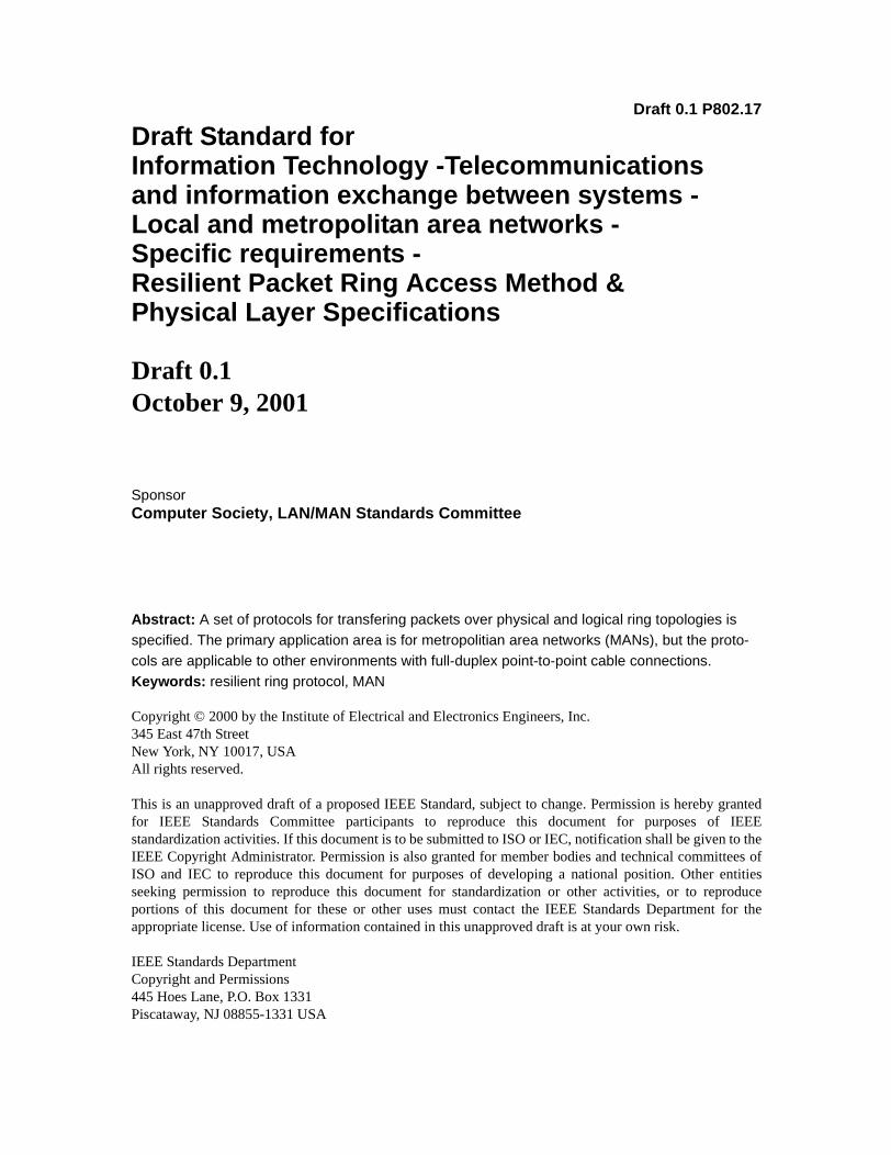
2.2 Spatial Reuse
Spatial Reuse is a concept used in rings to increase the overall aggregate bandwidth of the ring. This is pos-sible because unicast traffic is only passed along ring spans between source and destination nodes ratherthan the whole ring as in earlier ring based protocols such as token ring and FDDI.
Figure 1 below outlines how spatial reuse works. In this example, node 1 is sending traffic to node 4, node 2to node 3 and node 5 to node 6. Having the destination node strip unicast data from the ring allows othernodes on the ring who are downstream to have full access to the ring bandwidth. In the example given thismeans node 5 has full bandwidth access to node 6 while other traffic is being simultaneously transmitted onother parts of the ring..
Inner Ring
Node 6Node 1
Node 5
Node 3
Node 2
Node 4Outer Ring
Traffic Flow
Figure 1—Global and Local Reuse
10

9/9/01 Draft ProposalRESILIENT PACKET RING (RPR) P802.17
2.3 Fairness
Since the ring is a shared media, some sort of access control is necessary to ensure fairness and to boundlatency. Access control can be broken into two types which can operate in tandem:
Global access control - controls access so that everyone gets a fair share of the global bandwidth ofthe ring.
Local access control - grants additional access beyond that allocated globally to take advantage ofsegments of the ring that are less than fully utilized.
As an example of a case where both global and local access are required, refer again to Figure 1. Nodes 1, 2,and 5 will get 1/2 of the bandwidth on a global allocation basis. But from a local perspective, node 5 shouldbe able to get all of the bandwidth since its bandwidth does not interfere with the fair shares of nodes 1 and 2
2.4 Transit Buffer
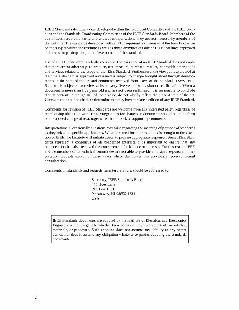
To be able to detect when to transmit and receive packets from the ring, RPR makes use of a transit buffer asshown in Figure 2 below. Traffic will be separated into three priorities, High, Medium and Low. High prior-ity will be placed into one fifo queue, and Medium and Low priority will utilize another.
High Pri Transit Buffer
M/L Pri Transit BufferIncoming Traffic
Rx
Buf
fer
HP
Transm
itB
uffer
Figure 2—Transit / Transmit Buffer Design
MP
Transm
itB
uffer
LP
Transm
itB
uffer
11

Draft Proposal 9/9/01P802.17 RESILIENT PACKET RING (RPR)
3. RPR Overview
3.1 Receive Operation Overview
Receive Packets entering a node are copied to the receive buffer if a Destination Address (DA) match ismade. If a DA matched packet is also a unicast, then the packet will be stripped. If a packet does not DAmatch or is a multicast and the packet does not Source Address (SA) match, then the packet is placed intothe Transit Buffer (TB) for forwarding to the next node if the packet passes Time To Live and Cyclic Redun-dancy Check (CRC) tests.
3.2 Transmit Operation Overview
Data sent from the node is either forwarded data from the TB or transmit data originating from the node viathe Tx Buffer. High priority forwarded data always gets sent first. High priority transmit data may be sent aslong as the Low Priority Transit Buffer (LPTB) is not almost full. Medium Priority transmit traffic will beassigned a Committed Access Rate (CAR). Any traffic within the CAR is treated as if it is HP, and can besent as long as the LPTB is not almost full. Medium Priority traffic above the CAR will be treated as LP traf-fic, and will be referred to as “excess” MP traffic, or eMP.
A set of usage counters monitor the rate at which Low Priority and excess Medium Priority transmit data aresent. This traffic may be sent as long as the usage counters does not exceed an allowed usage governed bythe RPR-fa rules and the LPTB has not exceeded the low priority threshold.
3.3 RPR Fairness Algorithm (RPR-fa) Overview
The RPR-fa is a mechanism that enforces fairness among the nodes on the ring. It applies only to LP andeMP traffic coming from the MAC client. Each node is assigned a weight, which allows the user to allocatemore ring bandwidth to certain nodes.
There are two possible implementations of RPR-fa. Basic RPR-fa is implemented completely in the MAC,and does not understand the ring topology. Multi-choke RPR-fa is an enhancement to Basic RPR-fa that uti-lizes topology information along with per-destination transmit queuing to increase ring utilization.
In Basic RPR-fa, if a node experiences congestion, it will advertise the value of its transmit usage counter toupstream nodes via the opposite ring. The usage counter is run through a low pass filter function and dividedby the node’s weight. The low-pass filter stabilizes the feedback, and the division by weight normalizes thetransmitted value to a weight of 1.0. When they receive an advertised usage value, upstream nodes willadjust their transmit rates so as not to exceed the advertised value (adjusted by their weights). Nodes alsopropagate the advertised value received to their immediate upstream neighbor. Nodes receiving advertisedvalues who are also congested propagate the minimum of their normalized low pass filtered transmit usageand the received usage.
Multi-choke RPR-fa is an enhancement to RPR-fa that deals with the case where a node wants to send trafficto a destination that is closer than a congested link. As an example, consider the case where node 1 wants tosend traffic to node 2, and the link between nodes 2 and 3 is congested. Basic RPR-fa will limit node 1’s traf-fic, even though the congestion point is further away than the destination. Multi-Choke RPR-fa will allownode 1 to send as much traffic as it wants to node 2, and will only limit traffic to nodes beyond the congestedlink.
In Multi-choke RPR-fa each node will track advertised usage values for n congested nodes, where n isadjustable from 1 to 4. A node is allowed to send unlimited traffic to any node between itself and the firstcongested node (choke point). It can send traffic to nodes between the first and second choke point based on
12

9/9/01 Draft ProposalRESILIENT PACKET RING (RPR) P802.17
the first choke point’s advertised usage value. In general, a node can send traffic to a particular destination ifit has satisfied the usage conditions for all choke points between itself and the destination.
Congestion is detected when the depth of the low priority transit buffer reaches a congestion threshold.
Usage messages are generated periodically and also act as keepalives informing the upstream station that avalid data link exists.
3.3.1 Inter operability between single/dual transit buffer fairness schemes
If a ring consists of mixed RPR nodes (single and dual transit buffer nodes), their fairness schemes will needto interact. This will require a global congestion message format.
The RPR node can easily interact with a non- RPR single transit buffer node. Upon receiving a foreign con-gestion message the RPR node will cut its allowed usage by a pre-determined percentage, and then forwardthe message upstream. Over time, the RPR node will increase its allowed usage back to its pre-determinedmaximum value.
Also, when in a mixed ring, the RPR nodes should be rate limited on their outputs to a predetermined per-centage of line rate. This will be done by inserting gaps between packets on the output line. This is neededbecause small single transit buffers require idle cycles in the traffic stream to ensure that they empty occa-sionally. In this type of implementation if the transit buffer does not empty, no transmit traffic will be sent.The large dual transit buffers in an RPR node can burst at line rate for long periods of time, which mightstarve a neighboring single transit buffer node.
3.3.2 MAC client interface considerations
An RPR node will have 3 software configurable rate shapers that control access from the MAC client. Thereis one shaper each for HP, MP, and LP traffic. The shapers are simple token buckets, and if a bucket emptiesthe RPR node communicates with the MAC client on 3 pins: STOP_HIGH, STOP_MED and STOP_LOW.If the client ignores the pins and sends the traffic anyway, the RPR node will not schedule the client until thetoken bucket has a token in it.
The MAC-client interface also includes special information in Multi-choke RPR-fa. In this mode, the MACwill pass choke point information to the MAC client. The information will include the MAC address andnormalized usage value for any congested nodes. The information will come directly from the receivedusage messages.
3.4 Intelligent Protection Switching (IPS) Protocol Overview
Resiliency is one of RPR objectives. The goal is to provide protection within 50ms in case of ring or nodefailure. There are two known mechanisms: wrapping and steering. IPS will support both mechanisms.
During the topology discovery, every node will indicate if it supports wrap protection or not. If it is ahomogenous network where all nodes are able to wrap, IPS will use the wrap protection scheme. Otherwise,IPS will use the steering protection scheme.
3.4.1 Wrap Protection
An RPR Ring is composed of two counter-rotating, single fiber rings. If an equipment or fiber facility failureis detected, traffic going towards and from the failure direction is wrapped (looped) back to go in the oppo-site direction on the other ring (subject to the protection hierarchy). Wrapping takes place on the nodes adja-
13
Draft Proposal 9/9/01P802.17 RESILIENT PACKET RING (RPR)
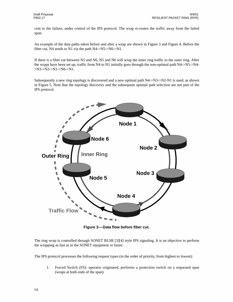
cent to the failure, under control of the IPS protocol. The wrap re-routes the traffic away from the failedspan.
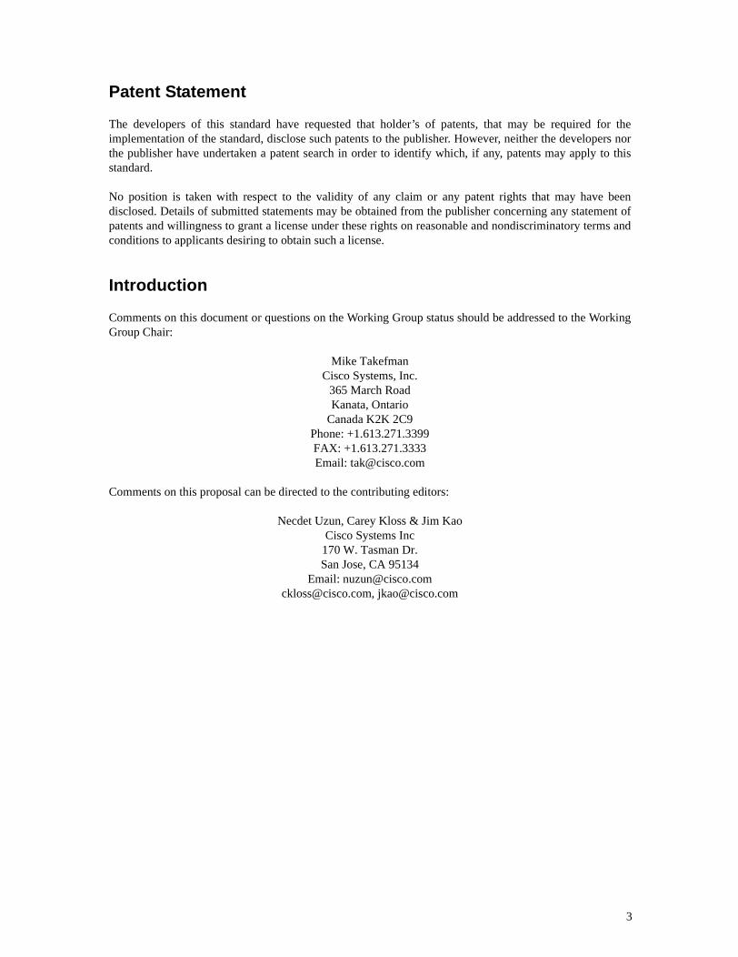
An example of the data paths taken before and after a wrap are shown in Figure 3 and Figure 4. Before thefiber cut, N4 sends to N1 via the path N4->N5->N6->N1.
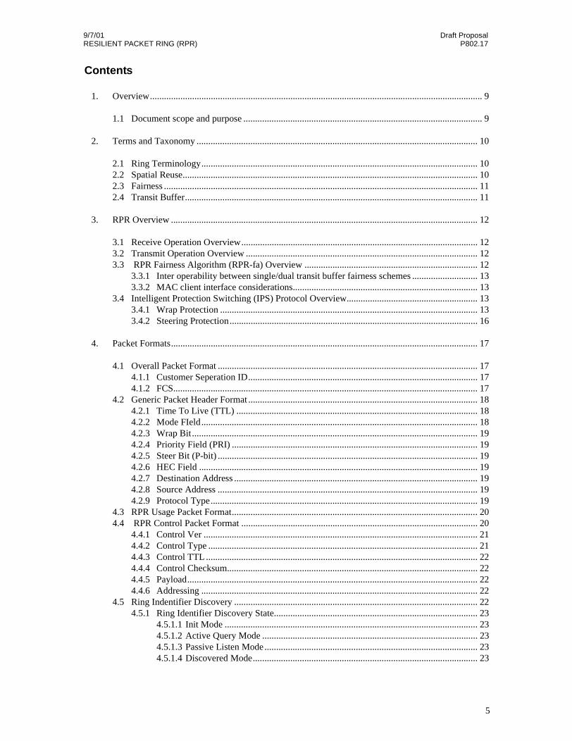
If there is a fiber cut between N5 and N6, N5 and N6 will wrap the inner ring traffic to the outer ring. Afterthe wraps have been set up, traffic from N4 to N1 initially goes through the non-optimal path N4->N5->N4->N3->N2->N1->N6->N1.
Subsequently a new ring topology is discovered and a new optimal path N4->N3->N2-N1 is used, as shownin Figure 5. Note that the topology discovery and the subsequent optimal path selection are not part of theIPS protocol.
The ring wrap is controlled through SONET BLSR [3][4] style IPS signaling. It is an objective to performthe wrapping as fast as in the SONET equipment or faster.
The IPS protocol processes the following request types (in the order of priority, from highest to lowest):
1. Forced Switch (FS): operator originated, performs a protection switch on a requested span(wraps at both ends of the span)
Inner Ring
Node 6
Node 1
Node 5Node 3
Node 2
Node 4
Outer Ring
Traffic Flow
Figure 3—Data flow before fiber cut.
14

9/9/01 Draft ProposalRESILIENT PACKET RING (RPR) P802.17
2. Signal Fail (SF): automatic, caused by a media Signal Failure or RPR keep-alive failure - per-forms a protection switch on a requested span
3. Signal Degrade (SD): automatic, caused by a media Signal Degrade (e.g. excessive Bit ErrorRate) - performs a protection switch on a requested span
4. Manual Switch (MS): operator originated, like Forced Switched but of a lower priority5. Wait to Restore (WTR): automatic, entered after the working channel meets the restoration cri-
teria after SF or SD condition disappears. IPS waits WTR period before restoring traffic inorder to prevent protection switch oscillations
Inner Ring
Node 6 Node 1
Node 5Node 3
Node 2
Node 4
Outer Ring
Traffic Flow
Fiber Cut
Figure 4—Data Path after Wrap
15
Draft Proposal 9/9/01P802.17 RESILIENT PACKET RING (RPR)
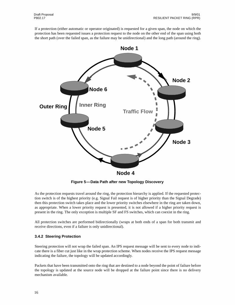
If a protection (either automatic or operator originated) is requested for a given span, the node on which theprotection has been requested issues a protection request to the node on the other end of the span using boththe short path (over the failed span, as the failure may be unidirectional) and the long path (around the ring).
As the protection requests travel around the ring, the protection hierarchy is applied. If the requested protec-tion switch is of the highest priority (e.g. Signal Fail request is of higher priority than the Signal Degrade)then this protection switch takes place and the lower priority switches elsewhere in the ring are taken down,as appropriate. When a lower priority request is presented, it is not allowed if a higher priority request ispresent in the ring. The only exception is multiple SF and FS switches, which can coexist in the ring.
All protection switches are performed bidirectionally (wraps at both ends of a span for both transmit andreceive directions, even if a failure is only unidirectional).
3.4.2 Steering Protection
Steering protection will not wrap the failed span. An IPS request message will be sent to every node to indi-cate there is a fiber cut just like in the wrap protection scheme. When nodes receive the IPS request messageindicating the failure, the topology will be updated accordingly.
Packets that have been transmitted onto the ring that are destined to a node beyond the point of failure beforethe topology is updated at the source node will be dropped at the failure point since there is no deliverymechanism available.
Inner Ring
Node 6
Node 1
Node 5
Node 3
Node 2
Node 4
Outer RingTraffic Flow
Figure 5—Data Path after new Topology Discovery
16

9/9/01 Draft ProposalRESILIENT PACKET RING (RPR) P802.17
4. Packet Formats
This section describes the packet formats used by RPR. Packets can be sent over any point to point link layer(e.g. SONET/SDH, point to point ETHERNET connections). The maximum transfer unit (MTU) is 9216octets. The minimum transfer unit for data packets is 42octets.
These limits include everything listed in Figure 6 but are exclusive of the frame delineation (e.g. for RPRover SONET/SDH, the flags used for frame delineation are not included in the size limits).
The following packet format does not include any layer 1 frame delineation. For RPR over POS, there willbe an additional flag that delineates start and end of frame.
4.1 Overall Packet Format
The overall packet format is show below in Figure 6:
4.1.1 Destination Address
The destination address is a globally unique 48 bit address assigned by the IEEE.
4.1.2 Source Address
The source address is a globally unique 48 bit address assigned by the IEEE.
15 14 13 12 11 10 9 8 7 6 5 4 3 2 1 0
Destination Address
Source Address
47
0
47
0
Protocol Type
FCS31
0
PAYLOAD
Figure 6—Overall Packet Format
RPR Header
HEC
(Optional) Customer Seperation ID0
32
Eth
ernet
Versio
n2
17
Draft Proposal 9/9/01P802.17 RESILIENT PACKET RING (RPR)
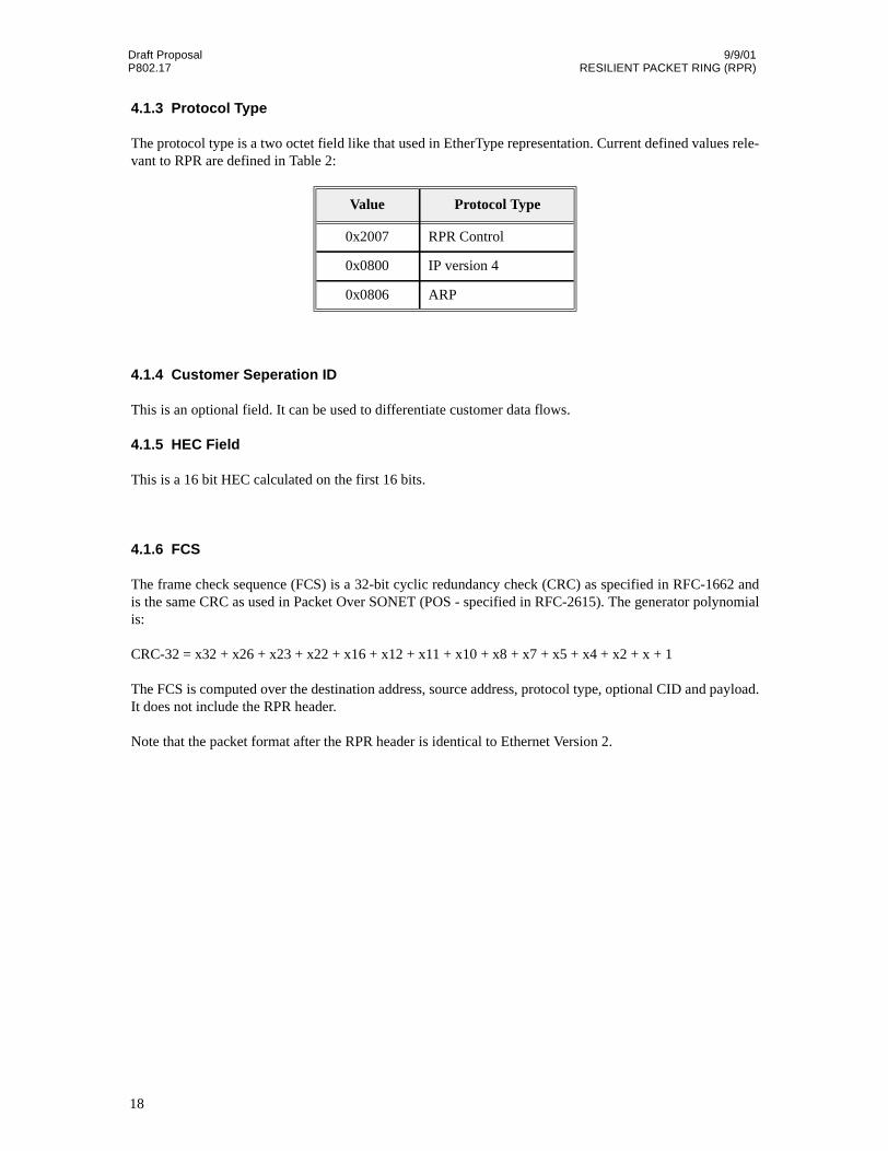
4.1.3 Protocol Type
The protocol type is a two octet field like that used in EtherType representation. Current defined values rele-vant to RPR are defined in Table 2:
4.1.4 Customer Seperation ID
This is an optional field. It can be used to differentiate customer data flows.
4.1.5 HEC Field
This is a 16 bit HEC calculated on the first 16 bits.
4.1.6 FCS
The frame check sequence (FCS) is a 32-bit cyclic redundancy check (CRC) as specified in RFC-1662 andis the same CRC as used in Packet Over SONET (POS - specified in RFC-2615). The generator polynomialis:
CRC-32 = x32 + x26 + x23 + x22 + x16 + x12 + x11 + x10 + x8 + x7 + x5 + x4 + x2 + x + 1
The FCS is computed over the destination address, source address, protocol type, optional CID and payload.It does not include the RPR header.
Note that the packet format after the RPR header is identical to Ethernet Version 2.
Value Protocol Type
0x2007 RPR Control
0x0800 IP version 4
0x0806 ARP
18
9/9/01 Draft ProposalRESILIENT PACKET RING (RPR) P802.17
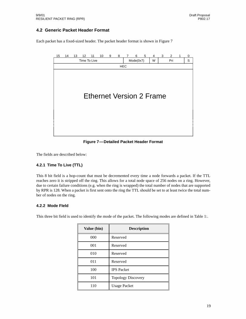
4.2 Generic Packet Header Format
Each packet has a fixed-sized header. The packet header format is shown in Figure 7
The fields are described below:
4.2.1 Time To Live (TTL)
This 8 bit field is a hop-count that must be decremented every time a node forwards a packet. If the TTLreaches zero it is stripped off the ring. This allows for a total node space of 256 nodes on a ring. However,due to certain failure conditions (e.g. when the ring is wrapped) the total number of nodes that are supportedby RPR is 128. When a packet is first sent onto the ring the TTL should be set to at least twice the total num-ber of nodes on the ring.
4.2.2 Mode FIeld
This three bit field is used to identify the mode of the packet. The following modes are defined in Table 1:.
Value (bin) Description
000 Reserved
001 Reserved
010 Reserved
011 Reserved
100 IPS Packet
101 Topology Discovery
110 Usage Packet
15 14 13 12 11 10 9 8 7 6 5 4 3 2 1 0
Time To Live WMode(0x7) Pri S
Figure 7—Detailed Packet Header Format
HEC
Ethernet Version 2 Frame
19
Draft Proposal 9/9/01P802.17 RESILIENT PACKET RING (RPR)
Table 1—Mode Values
These modes will be further explained in later sections.
4.2.3 Wrap Bit
This bit indicates that the packet has been wrapped when it is set to 1.
4.2.4 Priority Field (PRI)
This three bit field indicates the priority level of the RPR packet (0 through 7). The higher the value thehigher the priority. Since there are only two queues in the transit buffer (HPTB and LPTB) a packet is treatedas either low or high priority once it is on the ring. Each node determines the threshold value for determiningwhat is considered a high priority packet and what is considered a low priority packet. However, the full 8levels of priority in the RPR header can be used prior to transmission onto the ring (transmit queues) as wellas after reception from the ring (receive queues).
4.2.5 Steer Bit (P-bit)
The Steer bit indicates that this packet should not be wrapped.
Table 2—Defined Protocol Types
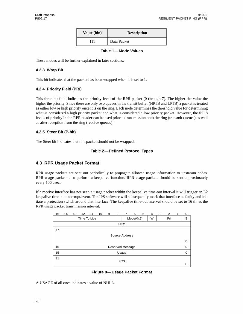
4.3 RPR Usage Packet Format
RPR usage packets are sent out periodically to propagate allowed usage information to upstream nodes.RPR usage packets also perform a keepalive function. RPR usage packets should be sent approximatelyevery 106 usec.
If a receive interface has not seen a usage packet within the keepalive time-out interval it will trigger an L2keepalive time-out interrupt/event. The IPS software will subsequently mark that interface as faulty and ini-tiate a protection switch around that interface. The keepalive time-out interval should be set to 16 times theRPR usage packet transmission interval.
A USAGE of all ones indicates a value of NULL.
111 Data Packet
Value (bin) Description
0
Usage
FCS31
0
Reserved Message
15 0
15
47
0
Source Address
Figure 8—Usage Packet Format
15 14 13 12 11 10 9 8 7 6 5 4 3 2 1 0
Time To Live WMode(0x6) Pri S
HEC
20
9/9/01 Draft ProposalRESILIENT PACKET RING (RPR) P802.17
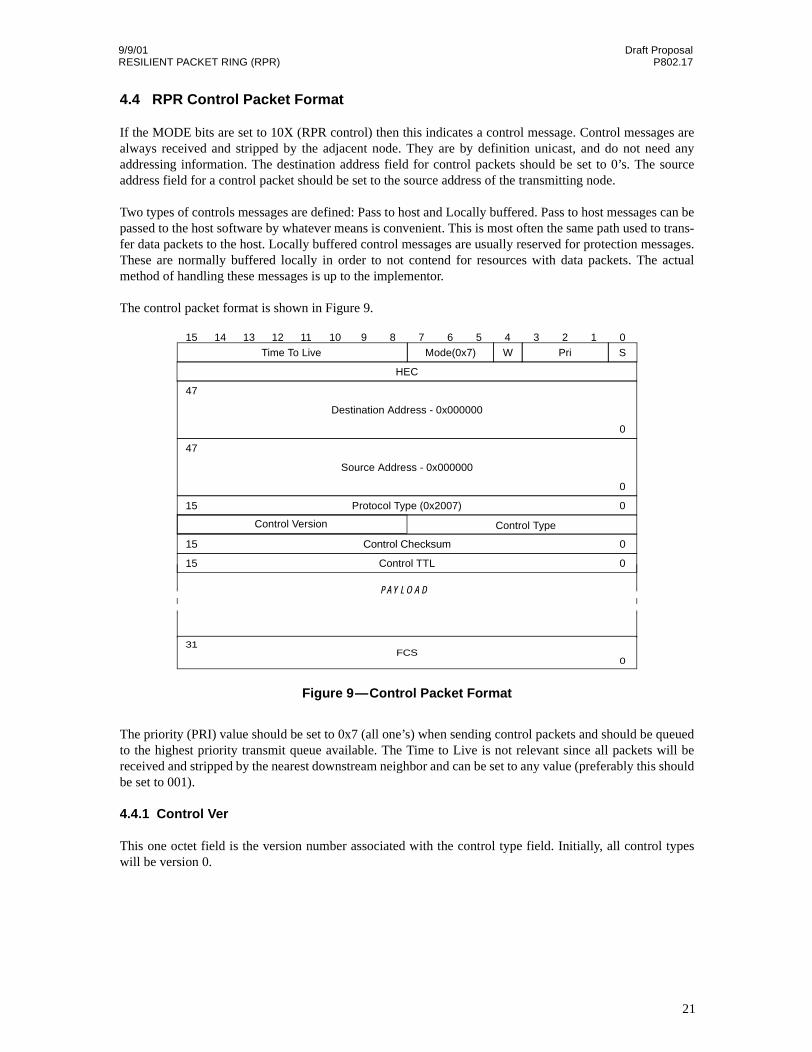
4.4 RPR Control Packet Format
If the MODE bits are set to 10X (RPR control) then this indicates a control message. Control messages arealways received and stripped by the adjacent node. They are by definition unicast, and do not need anyaddressing information. The destination address field for control packets should be set to 0’s. The sourceaddress field for a control packet should be set to the source address of the transmitting node.
Two types of controls messages are defined: Pass to host and Locally buffered. Pass to host messages can bepassed to the host software by whatever means is convenient. This is most often the same path used to trans-fer data packets to the host. Locally buffered control messages are usually reserved for protection messages.These are normally buffered locally in order to not contend for resources with data packets. The actualmethod of handling these messages is up to the implementor.
The control packet format is shown in Figure 9.
The priority (PRI) value should be set to 0x7 (all one’s) when sending control packets and should be queuedto the highest priority transmit queue available. The Time to Live is not relevant since all packets will bereceived and stripped by the nearest downstream neighbor and can be set to any value (preferably this shouldbe set to 001).
4.4.1 Control Ver
This one octet field is the version number associated with the control type field. Initially, all control typeswill be version 0.
Control Type
Control Checksum
Destination Address - 0x000000
Source Address - 0x000000
47
0
47
0
Protocol Type (0x2007)
PAYLOAD
15
15 0
0
Control Version
Control TTL15 0
Figure 9—Control Packet Format
FCS31
0
15 14 13 12 11 10 9 8 7 6 5 4 3 2 1 0
Time To Live WMode(0x7) Pri S
HEC
21
Draft Proposal 9/9/01P802.17 RESILIENT PACKET RING (RPR)
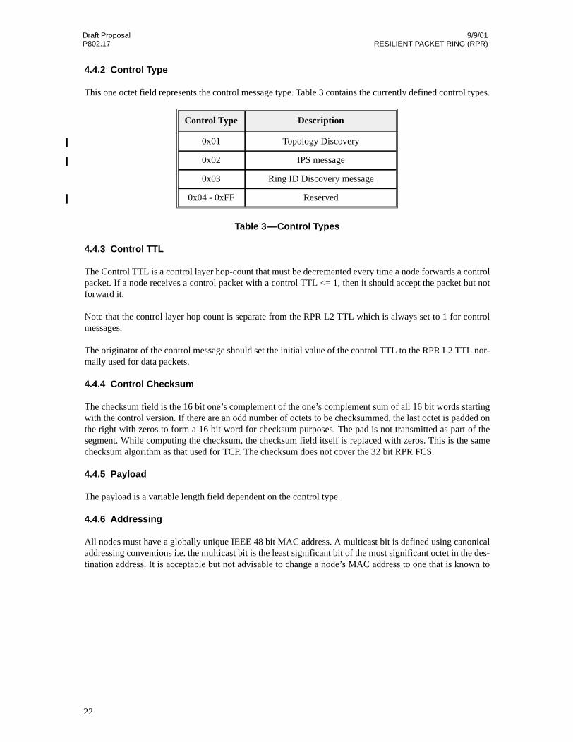
4.4.2 Control Type
This one octet field represents the control message type. Table 3 contains the currently defined control types.
Table 3—Control Types
4.4.3 Control TTL
The Control TTL is a control layer hop-count that must be decremented every time a node forwards a controlpacket. If a node receives a control packet with a control TTL <= 1, then it should accept the packet but notforward it.
Note that the control layer hop count is separate from the RPR L2 TTL which is always set to 1 for controlmessages.
The originator of the control message should set the initial value of the control TTL to the RPR L2 TTL nor-mally used for data packets.
4.4.4 Control Checksum
The checksum field is the 16 bit one’s complement of the one’s complement sum of all 16 bit words startingwith the control version. If there are an odd number of octets to be checksummed, the last octet is padded onthe right with zeros to form a 16 bit word for checksum purposes. The pad is not transmitted as part of thesegment. While computing the checksum, the checksum field itself is replaced with zeros. This is the samechecksum algorithm as that used for TCP. The checksum does not cover the 32 bit RPR FCS.
4.4.5 Payload
The payload is a variable length field dependent on the control type.
4.4.6 Addressing
All nodes must have a globally unique IEEE 48 bit MAC address. A multicast bit is defined using canonicaladdressing conventions i.e. the multicast bit is the least significant bit of the most significant octet in the des-tination address. It is acceptable but not advisable to change a node’s MAC address to one that is known to
Control Type Description
0x01 Topology Discovery
0x02 IPS message
0x03 Ring ID Discovery message
0x04 - 0xFF Reserved
22

9/9/01 Draft ProposalRESILIENT PACKET RING (RPR) P802.17
be unique within the administrative layer 2 domain (that is the RPR ring itself along with any networks con-nected to the RPR ring via a layer 2 transparent bridge).
Note that for SONET media, the network order is MSB of each octet first, so that as viewed on the line, themulticast bit will be the 8th bit of the destination address sent. (For RPR on Ethernet media, the multicast bitwould be sent first).
4.5 Ring Indentifier Discovery
The Ring Identifier is used to distinguish the inner/outer ring in RPR control protocol like topology discov-ery. This Ring Identifier can be predefined for the inner/outer rings. However, that requires the propercabling attention. Otherwise the ring will not operate properly if the Ring Identifier is not consistent betweennodes within the same ring.
The Ring Identifier discovery mechanism is used to automatically discover the Ring Identifier while a nodeis joining the ring.
4.5.1 Ring Identifier Discovery State
There are four states in the Ring Identifier discovery phase.
4.5.1.1 Init Mode
This is the initialization state. A Ring Identifier query packet will be sent to the ring and the node will waitfor the response.
4.5.1.2 Active Query Mode
After the node sends out the Ring Identifier query, it will stay in this mode and wait for the response.
4.5.1.3 Passive Listen Mode
If a node receives a Ring Identifier query with a smaller SA before receiving its query response, the nodewill enter into this mode. Because there is a node with a higher privilege querying the Ring Identifier.
4.5.1.4 Discovered Mode
The global Ring Identifier is assigned to the ring. The node has gotten the Ring Identifier.
4.5.2 Ring ID Discovery Rule
R.I.1
While a node is coming up, it assigns a local Ring ID to its MAC and inverse to its Mate
Destination Address
0 1 2 3 4 5 6 7 8 9 0 1 2 3 4 5 6 7 8 9 0 1 2 3 4 5 6 7 8 9 0 1 2 3 4 5 6 7 8 9 0 1 2 3 4 5 6 70 1 2 43
M
Multicast Bit
Figure 10—Multicast Bit Position
23
Draft Proposal 9/9/01P802.17 RESILIENT PACKET RING (RPR)
R.I.2
A Ring ID query will be sent to the ring right after a RPR node joins the ring
R.I.3
A node in the Discovered Mode will respond the Ring ID query by providing its Ring ID
R.I.4
If there is not a node in the Discovered Mode, the Ring ID assignment of the node with the smallest MACaddress will overwrite others
R.I.5
A node in Active Query Mode will compare the original SA in Ring ID query packet with its MAC address-
— If node’s MAC address is bigger than the SA, the query packet will be passed to the downstreamnode
— If node’s MAC address is smaller than the SA, the query packet will be dropped
R.I.6
If the Ring ID query packet is circulated around the whole ring and received back by the original node fromthe same ring, this node must have the smallest MAC address. Hence, it will assign the global Ring ID.
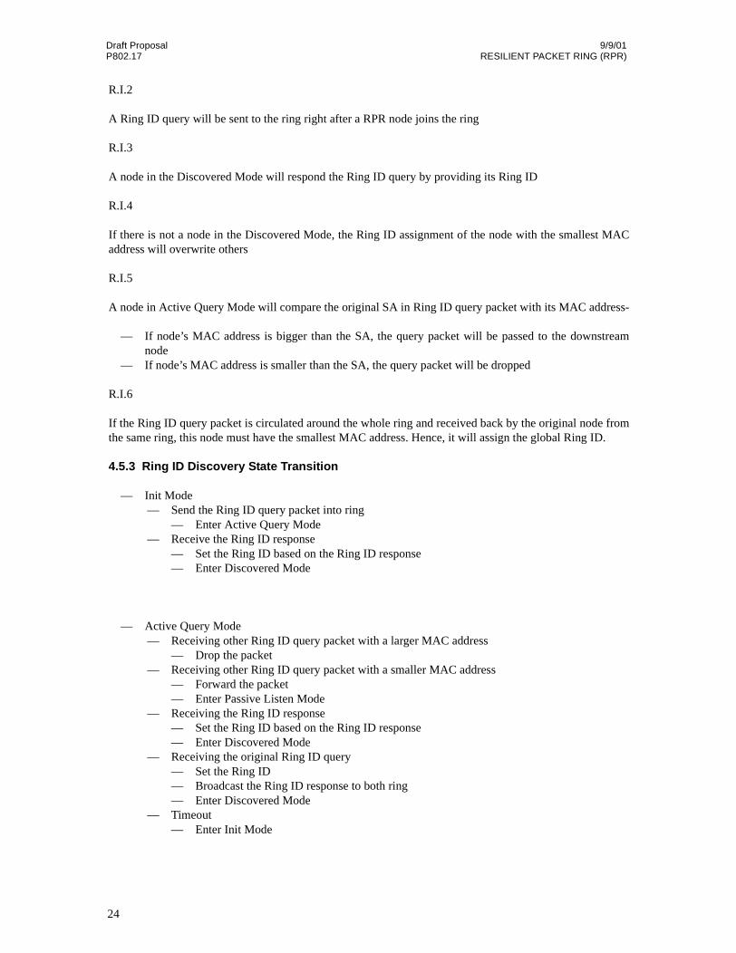
4.5.3 Ring ID Discovery State Transition
— Init Mode— Send the Ring ID query packet into ring
— Enter Active Query Mode— Receive the Ring ID response
— Set the Ring ID based on the Ring ID response— Enter Discovered Mode
— Active Query Mode— Receiving other Ring ID query packet with a larger MAC address
— Drop the packet— Receiving other Ring ID query packet with a smaller MAC address
— Forward the packet— Enter Passive Listen Mode
— Receiving the Ring ID response— Set the Ring ID based on the Ring ID response— Enter Discovered Mode
— Receiving the original Ring ID query— Set the Ring ID— Broadcast the Ring ID response to both ring— Enter Discovered Mode
— Timeout— Enter Init Mode
24

9/9/01 Draft ProposalRESILIENT PACKET RING (RPR) P802.17
— Passive Listen Mode— Receiving the original Ring ID query
— Enter Init Mode— Receiving the Ring ID response
— Set the Ring ID— Enter the Discovered Mode
— Timeout— Enter Init Mode
— Discovered Mode— Receiving a Ring ID query
— Sent a Ring ID response— Receiving a unmatched Ring ID response
— Enter the Init Mode
Init
ActiveQuery
send RI Query todownstream
PassiveListen
TimeOut or Rev eiv e Original RI Query
Discovered
Receiv e OriginalRI Query /set RI,
broadcast RI Response
TimeOut
Receiv e RI Query/sent RI Response
RI Query with larger MACaddress/drop the packet
RI Query with smaller MAC address/forward the packet
Receiv e RIResponse/Set RI
Receiv eRI
Response
Unmatched RIResponse
Receiv e RIResponse/Set RI
Figure 11—Ring ID Discovery State Transition Diagram
25

Draft Proposal 9/9/01P802.17 RESILIENT PACKET RING (RPR)
4.5.4 Ring ID Discovery Packet Format
4.5.5 Ring ID Octet
The Ring ID octet contains the Ring ID discovery packet type information. The format of the Ring ID octetis as follows:
This 8 bit field is encoded as follows:
Table 4—Ring ID Octet
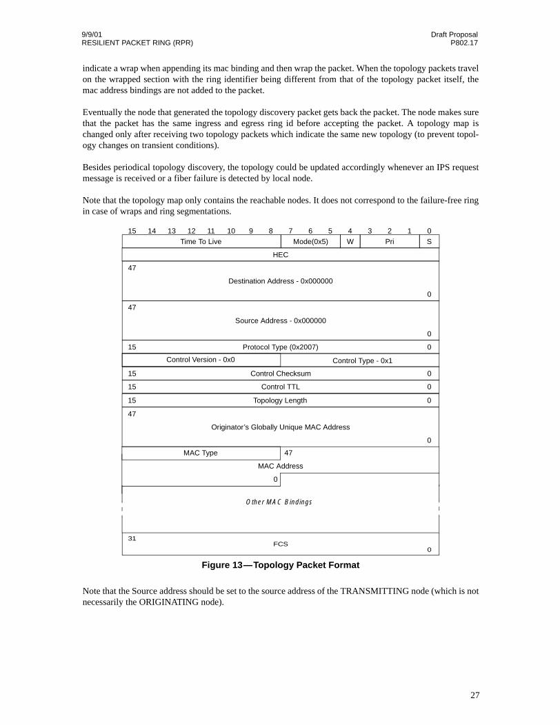
4.6 Topology Discovery
Each node performs a topology discovery by sending out topology discovery packets on one or both rings.The node originating a topology packet marks the packet with the egressing ring id, appends the node’s macbinding to the packet and sets the length field in the packet before sending. This packet is a point-to-pointpacket which hops around the ring from node to node. Each node appends its mac address binding, updatesthe length field and sends it to the next hop on the ring. If there is a wrap on the ring, the wrapped node will
Bit Value
0 Query(0)/Response(1)
1 Ring ID (1 or 0)
2-7 Reserved
Figure 12—Ring ID Discovery Packet Format
Control Type - 0x3
Control Checksum
Destination Address - 0x000000
Source Address - 0x000000
47
0
47
0
Protocol Type (0x2007)15
15 0
0
Control Version - 0x0
Control TTL15 0
FCS31
0
Originator’s Globally Unique MAC Address
47
0
Ring ID Octet
15 14 13 12 11 10 9 8 7 6 5 4 3 2 1 0
Time To Live WMode(0x5) Pri S
HEC
Reserved
26
9/9/01 Draft ProposalRESILIENT PACKET RING (RPR) P802.17
indicate a wrap when appending its mac binding and then wrap the packet. When the topology packets travelon the wrapped section with the ring identifier being different from that of the topology packet itself, themac address bindings are not added to the packet.
Eventually the node that generated the topology discovery packet gets back the packet. The node makes surethat the packet has the same ingress and egress ring id before accepting the packet. A topology map ischanged only after receiving two topology packets which indicate the same new topology (to prevent topol-ogy changes on transient conditions).
Besides periodical topology discovery, the topology could be updated accordingly whenever an IPS requestmessage is received or a fiber failure is detected by local node.
Note that the topology map only contains the reachable nodes. It does not correspond to the failure-free ringin case of wraps and ring segmentations.
Note that the Source address should be set to the source address of the TRANSMITTING node (which is notnecessarily the ORIGINATING node).
Control Type - 0x1
Control Checksum
Destination Address - 0x000000
Source Address - 0x000000
47
0
47
0
Protocol Type (0x2007)
Other MAC Bindings
15
15 0
0
Control Version - 0x0
Control TTL15 0
Figure 13—Topology Packet Format
FCS31
0
Topology Length15 0
Originator’s Globally Unique MAC Address
47
0
MAC Type
15 14 13 12 11 10 9 8 7 6 5 4 3 2 1 0
Time To Live WMode(0x5) Pri S
HEC
MAC Address
47
0
27

Draft Proposal 9/9/01P802.17 RESILIENT PACKET RING (RPR)
4.6.1 Topology Length
This two octet field represents the length of the topology message in octets starting with the first MACType/MAC Address binding.
4.6.2 Topology Originator
A topology discovery packet is determined to have been originated by a node if the originator’s globallyunique MAC address of the packet is that node’s globally unique MAC address (assigned by the IEEE).
Because the mac addresses could be changed at a node, the IEEE MAC address ensures that a unique identi-fier is used to determine that the topology packet has gone around the ring and is to be consumed.
4.6.3 MAC bindings
Each MAC binding shall consist of a MAC Type field followed by the node’s 48 bit MAC address. The firstMAC binding shall be the MAC binding of the originator. Usually the originator’s MAC address will be it’sglobally unique MAC Address but some implementations may allow this value to be overridden by the net-work administrator.
4.6.4 MAC Type Format
This 8 bit field is encoded as follows:
Table 5—MAC Type Format
Determination of whether a packet’s egress and ingress Ring ID’s are a match should be done by using theRing ID found in the MAC Type field of the last MAC binding as the ingress Ring ID.
The topology information is not required for the IPS protection mechanism. This information can be used tocalculate the number of nodes in the ring as well as to calculate hop distances to nodes to determine theshortest path to a node (since there are two counter-rotating rings).
The implementation of the topology discovery mechanism could be a periodic activity or on “a need to dis-cover” basis. In the periodic implementation, each node generates the topology packet periodically and usesthe cached topology map until it gets a new one. In the need to discover implementation, each node gener-ates a topology discovery packet whenever they need one e.g., on first entering a ring or detecting a wrap.
Bit Value
0 Reserved
1 Ring ID (1 or 0)
2 Wrapped Node (1) / Unwrapped Node (0)
3 Wrap Protection (1) / Steer Protection(0)
4-7 Reserved
28
9/9/01 Draft ProposalRESILIENT PACKET RING (RPR) P802.17
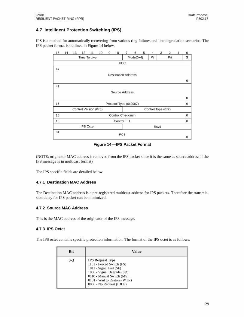
4.7 Intelligent Protection Switching (IPS)
IPS is a method for automatically recovering from various ring failures and line degradation scenarios. TheIPS packet format is outlined in Figure 14 below.
(NOTE: originator MAC address is removed from the IPS packet since it is the same as source address if theIPS message is in multicast format)
The IPS specific fields are detailed below.
4.7.1 Destination MAC Address
The Destination MAC address is a pre-registered multicast address for IPS packets. Therefore the transmis-sion delay for IPS packet can be minimized.
4.7.2 Source MAC Address
This is the MAC address of the originator of the IPS message.
4.7.3 IPS Octet
The IPS octet contains specific protection information. The format of the IPS octet is as follows:
Bit Value
0-3 IPS Request Type1101 - Forced Switch (FS)1011 - Signal Fail (SF)1000 - Signal Degrade (SD)0110 - Manual Switch (MS)0101 - Wait to Restore (WTR)0000 - No Request (IDLE)
Control Checksum15 0
Control Type (0x2)
Destination Address
Source Address
47
0
47
0
Protocol Type (0x2007)15 0
Control Version (0x0)
Control TTL15 0
Figure 14—IPS Packet Format
FCS31
0
15 14 13 12 11 10 9 8 7 6 5 4 3 2 1 0
Time To Live WMode(0x4) Pri S
HEC
RsvdIPS Octet
29

Draft Proposal 9/9/01P802.17 RESILIENT PACKET RING (RPR)
Table 6—IPS Octet Format
The currently defined request types with values, hierarchy and interpretation are as used in SONET BLSR[3], [4], except as noted.
4.8 Circulating packet detection (stripping)
Packets continue to circulate when transmitted packets fail to get stripped. Unicast packets are normallystripped by the destination station or by the source station if the destination station has failed. Multicastpackets are only stripped by the source station. If both the source and destination stations drop out of the ringwhile a unicast packet is in flight, or if the source node drops out while its multicast packet is in flight, thepacket will rotate around the ring continuously.
The solution to this problem is to have a TTL or Time To Live field in each packet that is set to at least twicethe number of nodes in the ring. As each node forwards the packet, it decrements the TTL. If the TTLreaches zero it is stripped off of the ring.
The Wrap bit is used to qualify all stripping and receive decisions. This is necessary to handle the case wherepackets are being wrapped by some node in the ring. The sending node may see its packet on the reverse ringprior to reaching its destination so must not source strip it. The exception is if a node is in wrap. Logically, anode in wrap “sees” the packet on both rings. However the usual implementation is to receive the packet onone ring and to transmit it on the other ring. Therefore, a node that is in the wrap state reversed the Wrap bitwhen making stripping and receiving decisions.
A potential optimization would be to allow Wrap bit independent destination stripping of unicast packets.One problem with this is that packets may be delivered out of order during a transition to a wrap condition.For this reason, the Wrap bit should always be used as a qualifier for all strip and receive decisions.
4 Path Indicator0 - Short (S)1 - Long (L)
5-7 Status Code010 - Protection Switch Completed - Traffic Wrapped (W)000 - Idle
Bit Value
30
9/9/01 Draft ProposalRESILIENT PACKET RING (RPR) P802.17
5. Packet acceptance and stripping
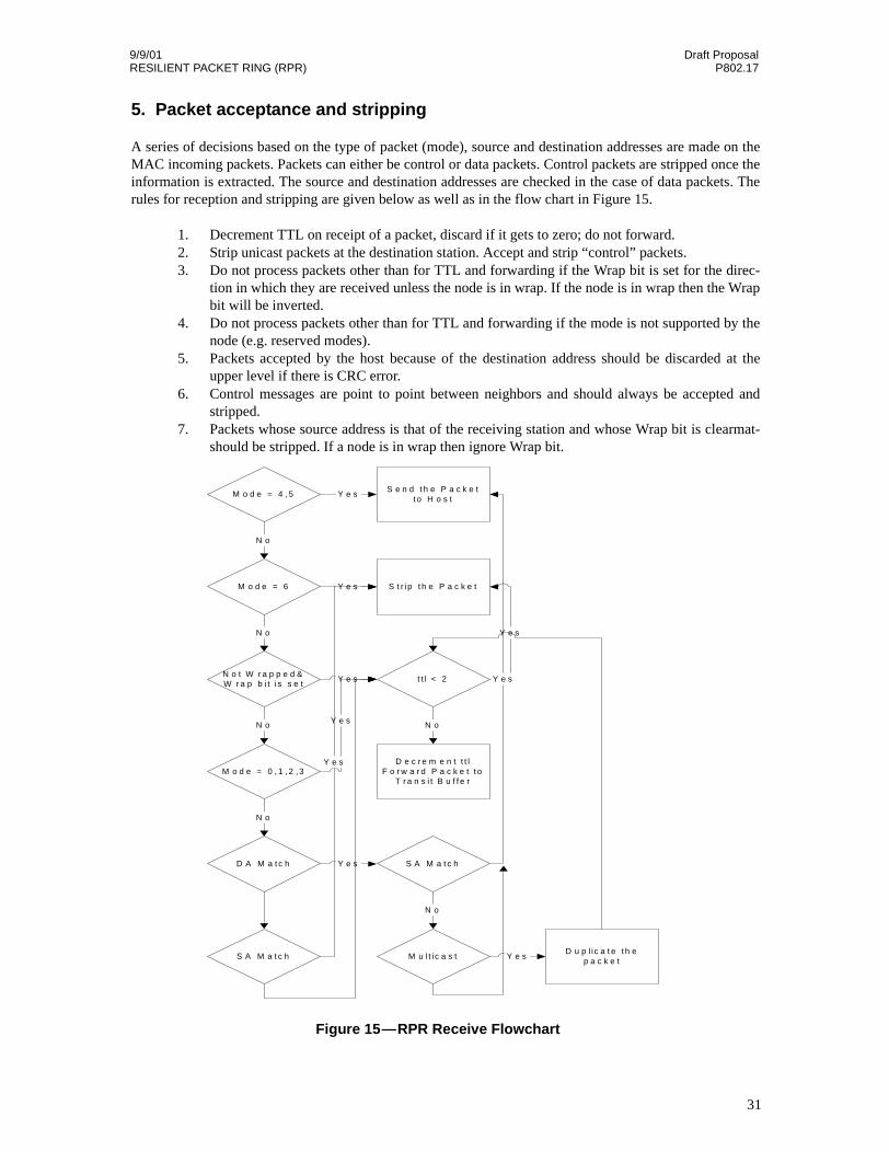
A series of decisions based on the type of packet (mode), source and destination addresses are made on theMAC incoming packets. Packets can either be control or data packets. Control packets are stripped once theinformation is extracted. The source and destination addresses are checked in the case of data packets. Therules for reception and stripping are given below as well as in the flow chart in Figure 15.
1. Decrement TTL on receipt of a packet, discard if it gets to zero; do not forward.2. Strip unicast packets at the destination station. Accept and strip “control” packets.3. Do not process packets other than for TTL and forwarding if the Wrap bit is set for the direc-
tion in which they are received unless the node is in wrap. If the node is in wrap then the Wrapbit will be inverted.
4. Do not process packets other than for TTL and forwarding if the mode is not supported by thenode (e.g. reserved modes).
5. Packets accepted by the host because of the destination address should be discarded at theupper level if there is CRC error.
6. Control messages are point to point between neighbors and should always be accepted andstripped.
7. Packets whose source address is that of the receiving station and whose Wrap bit is clearmat-should be stripped. If a node is in wrap then ignore Wrap bit.
M o d e = 4 , 5S e n d t h e P a c k e t
t o H o s t
N o t W r a p p e d &W r a p b i t i s s e t
t t l < 2
M o d e = 6 S t r ip t h e P a c k e t
M o d e = 0 , 1 , 2 , 3D e c r e m e n t t t l
F o r w a r d P a c k e t t oT r a n s i t B u f f e r
Y e s
N o
Y e s
N o
Y e s
N o
Y e s
N oY e s
D A M a t c h
N o
S A M a t c hY e s
M u l t ic a s t
Y e s
N o
S A M a t c hD u p l ic a t e t h e
p a c k e tY e s
Y e s
Figure 15—RPR Receive Flowchart
31

Draft Proposal 9/9/01P802.17 RESILIENT PACKET RING (RPR)
Notes: Host is responsible for discarding CRC errored packets. Conditionals (if statements) branch to theright if true and branch down if false..
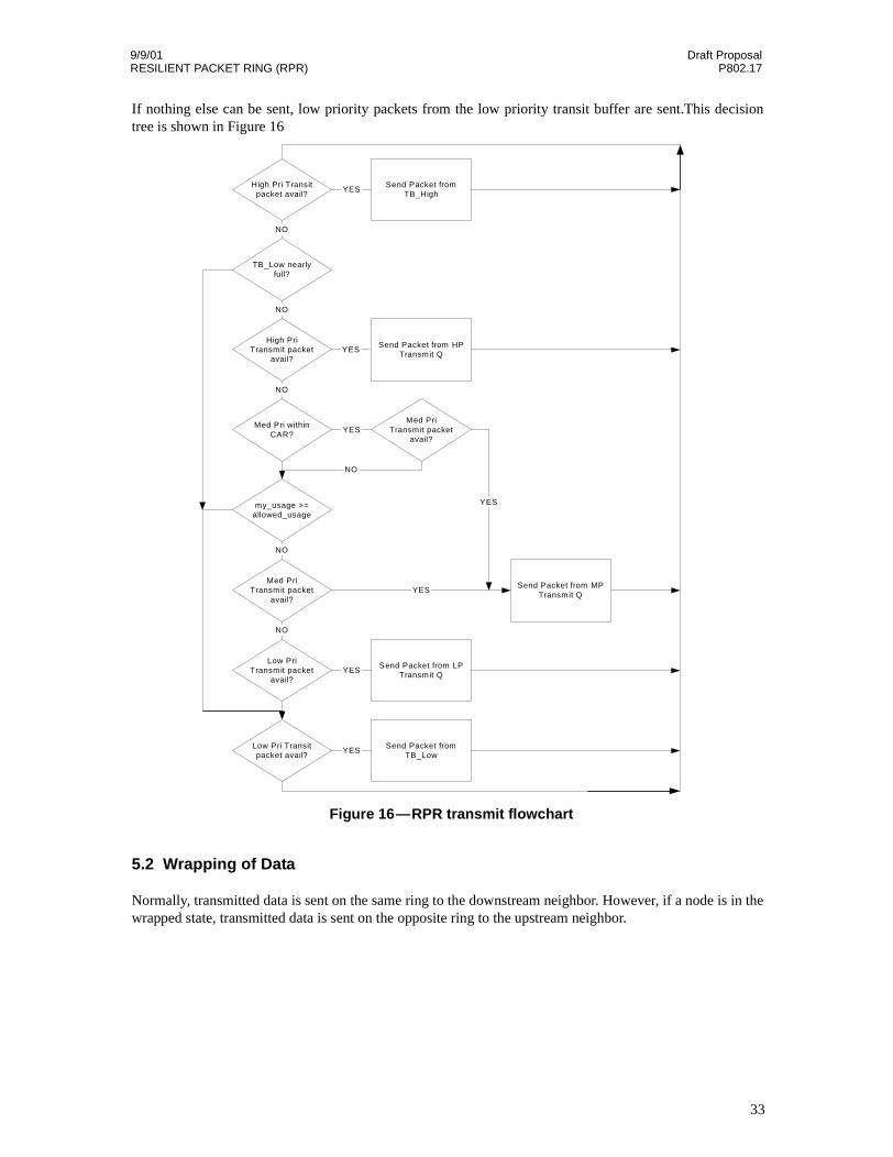
5.1 Transmission and forwarding with priority
A node can transmit six types of packets:
1. High priority packets from the high priority transit buffer.2. Medium priority packets from the low priority transit buffer3. Low priority packets from the low priority transit buffer.4. High priority packets from the host Tx high priority fifo.5. Medium priority packets from the host Tx medium priority fifo.6. Low priority packets from the host Tx low priority fifo.
High priority packets from the transit buffer are always sent first. High priority packets from the host aresent as long as the low priority transit buffer is not almost full. Medium priority packets from the host aresent if the medium priority traffic has not exceeded its CAR and the low priority transit buffer is not almostfull. The buffer is determined to be “almost” full if it surpasses a software controlled high priority thresholdvalue.
Excess Medium priority host traffic and low priority host traffic is sent if the low priority transit buffer hasnot crossed the low priority threshold and the RPR-fa rules allow it (my_usage < allowed_usage).
32
9/9/01 Draft ProposalRESILIENT PACKET RING (RPR) P802.17
If nothing else can be sent, low priority packets from the low priority transit buffer are sent.This decisiontree is shown in Figure 16
5.2 Wrapping of Data
Normally, transmitted data is sent on the same ring to the downstream neighbor. However, if a node is in thewrapped state, transmitted data is sent on the opposite ring to the upstream neighbor.
Send Packet fromTB_High
High Pri Transitpacket avail?
Send Packet from HPTransmit Q
High PriTransmit packet
avail?
TB_Low nearlyfull?
Med Pri withinCAR?
my_usage >=allowed_usage
Med PriTransmit packet
avail?
Send Packet from MPTransmit Q
Low PriTransmit packet
avail?
Send Packet from LPTransmit Q
Low Pri Transitpacket avail?
Send Packet fromTB_Low
Med PriTransmit packet
avail?
YES
NO
NO
NO
NO
NO
YES
YES
YES
YES
NO
YES
YES
Figure 16—RPR transmit flowchart
33
Draft Proposal 9/9/01P802.17 RESILIENT PACKET RING (RPR)
6. Fairness Algorithms
6.1 Basic RPR-fa Rules Of Operation
The RPR-fa governs access to the ring. The RPR-fa only applies to Low priority and excess Medium priority(eMP) traffic. High priority and “within CAR” Medium priority traffic does not follow RPR-fa rules andmay be transmitted at any time as long as there is sufficient low priority transit buffer space.
The RPR-fa requires three counters which control the traffic forwarded and sourced on the RPR ring. Thecounters are my_usage (tracks the amount of LP and eMP traffic sourced on the ring), forward_rate (amountof LP and MP traffic forwarded on to the ring from the LP transit buffer) and allowed_usage (the currentmaximum transmit usage for that node).
With no congestion, all nodes increment allowed_usage periodically. The maximum value forallowed_usage is max_usage. Max_usage is a per node parameter that limits the maximum amount ofLP/eMP traffic that a node can send.
When a node sees congestion it starts to advertise a normalized usage value to upstream nodes. The value(nlp_my_usage) is obtained by passing my_usage through a low pass filter and then dividing by its weight.In this way, the usage values passed on the links are always normalized to a weight of 1.0. Congestion isobserved when the LP transit buffer depth crosses a threshold.
A node that receives a non-null usage message (rcvd_usage) will set its allowed_usage to the rcvd_usagevalue multiplied by its weight. This allows a node with a weight of N to utilize N times as much bandwidthas a node with a weight of 1.0. If the source of the rcvd_usage is the same node that received it then thercvd_usage shall be treated as a null value. When comparing the rcvd_usage source address the ring ID ofthe usage packet must match the receiver’s ring ID in order to qualify as a valid compare. The exception is ifthe receive node is in the wrap state in which case the usage packet’s ring ID is ignored.
Nodes that are not congested and that receive a non-null rcvd_usage generally propagate rcvd_usage to theirupstream neighbor else propagate a null value of usage (all 1’s). An exception occurs when an opportunityfor local reuse is detected. The node compares its forward_rate (low pass filtered) to allowed_usage dividedby its weight. If the forward_rate is less than the normalized allowed_usage, then a null value is propagatedto the upstream neighbor instead of the rcvd_usage.
Nodes that are congested propagate the smaller of normalized lp_my_usage and rcvd_usage.
Convergence is dependent upon number of nodes and distance. Simulation has shown simulation conver-gence within 100 msec for rings of several hundred miles.
6.2 Multi-Choke RPR-fa
Multi-Choke RPR-fa uses the same algorithms for deciding fairness as Basic RPR-fa. The difference is thatit keeps track of 1-4 congestion locations (choke points), and uses this information to increase ring utiliza-tion and spacial reuse.
Multi-Choke RPR-fa requires access to topology information as well as per destination queuing in the MACclient. This will allow the MAC client to determine which destinations are located before the first chokepoint, which are between the first 2 choke points, etc.
The standard RPR-fa counters are kept for each destination queue. When a decision needs to be made for achoke point, the total of the my_usage values for all of the queues after the choke point are used as a
34

9/9/01 Draft ProposalRESILIENT PACKET RING (RPR) P802.17
total_my_usage value. This value is normalized and compared to the rcvd_usage value associated with thechoke point, as in the basic RPR-fa algorithm. To determine if a source node can send to a destination node,this calculation must be done (and satisfied) for each choke point until the destination. Also the total usageof all queues must be compared against max_usage.
As an example, imagine that there are 3 choke points at nodes 2, 4, and 6. Node 1 wants to send to node 5.The algorithm will check the total usage for destination nodes 3, 4, 5, ... against the rcvd usage for the chokepoint at 2. If that test passes, it will check the total usage for destination nodes 5, 6, ... against the rcvd_usagevalue for the choke point at node 4. Then a final check of the total usage for all nodes against max_usagewill be performed. If all tests pass then node 1 is allowed to send to node 5.
The benefit is obvious. Using Basic RPR-fa, all traffic is limited using rcvd_usage. If a node is trying to sendto its neighbor, and the congestion point is a few nodes away, this traffic will be penalized without reason.With Multi-Choke RPR-fa, though, this traffic will continue, and the link utilization before the choke pointwill increase.
6.3 RPR-fa pseudo-code
A more precise definition of the fairness algorithm is shown below.
Variables:
lo_tb_depth low priority transit buffer depth
my_usage count of LP and eMP octets transmitted by hostlp_my_usage my_usage run through a low pass filternlp_my_usage lp_my_usage / WEIGHT
my_usage_ok flag indicating that host is allowed to transmit
allowed_usage the fair amount each node is allowed to transmit
forward_rate count of octets forwarded from the LP transit bufferlp_forward_rate forward_rate run through low pass filter
congestednode cannot transmit host traffic without the TB bufferfilling beyond its congestion threshold point.
rcvd_usage the usage value received from the downstream neighbor
rev_usage the usage value passed along to the upstream neighbor
Constants:
WEIGHT = configurable weight for this node
MAX_ALLOWANCE = configurable value for max allowed usage for this node
DECAY_INTERVAL = 8000 octet times @ OC-12, 32,000 octet times @ OC-48
AGECOEFF = 4 // Aging coeff for my_usage and fwd_rate
LP_FWD = 64 // Low pass filter for fwd_rateLP_MU = 512 // Low pass filter for my usageLP_ALLOW = 64 // LP filter for allow usage auto increment
NULL_RCVD_INFO = All 1’s in rcvd_usage field
TB_LO_THRESHOLD // TB depth at which no more LP host traffic// can be sent
35
9/9/01 Draft ProposalRESILIENT PACKET RING (RPR) P802.17
MAX_LRATE = AGECOEFF * DECAY_INTERVAL = 512,000 for OC-192128,000 for OC-4832,000 for OC-12
THESE ARE UPDATED EVERY CLOCK CYCLE:
my_usage is incremented by 1 for every LP/eMP octet that istransmitted by the host (does not include datatransmitted from the Transit Buffer).
forward_rate is incremented by 1 for every octet that enters theLP Transit Buffer
if ((my_usage < allowed_usage) &&!((lo_tb_depth > 0) && (forward_rate < my_usage)) &&
(my_usage < MAX_ALLOWANCE)){my_usage_ok = true; // true means OK to send host packets
}
UPDATED WHEN USAGE_PKT IS RECEIVED:
if (usage_pkt.SA == my_SA) &&[(usage_pkt.RI == my_RingID) || (node_state == wrapped)] {rcvd_usage = NULL_RCVD_INFO;
} else {rcvd_usage = usage_pkt.usage;
}
THE FOLLOWING IS CALCULATED EVERY DECAY_INTERVAL:
congested = (lo_tb_depth > TB_LO_THRESHOLD/2)lp_my_usage = ((LP_MU-1) * lp_my_usage + my_usage) / LP_MUnlp_my_usage = lp_my_usage / WEIGHT
my_usage is decremented by min(allow_usage/AGECOEFF, my_usage/AGECOEFF)
lp_fwd_rate = ((LP_FWD-1) * lp_forward_rate + forward_rate) / LP_FWD
fwd_rate is decremented by forward_rate/AGECOEFF
(Note: lp values calculated prior to decrement of non-lp values).
if (rcvd_usage != NULL_RCVD_INFO) {allowed_usage = (rcvd_usage*WEIGHT);
} else {allowed_usage += (MAX_LRATE - allowed_usage) / (LP_ALLOW);
}
if (congested) {if (nlp_my_usage < rcvd_usage) {
rev_usage = nlp_my_usage;} else {
rev_usage = rcvd_usage;}
} else if ((rcvd_usage != NULL_RCVD_INFO) &&(lp_forward_rate > (allowed_usage/WEIGHT)) {
rev_usage = rcvd_usage;} else {
rev_usage = NULL_RCVD_INFO}
if (rev_usage > MAX_LRATE) {rev_usage = NULL_RCVD_INFO;
36
9/9/01 Draft ProposalRESILIENT PACKET RING (RPR) P802.17
}
6.4 Threshold settings
The high priority transit buffer needs to hold 2 to 3 MTUs or about 30KB.
The adequate sizing of the low priority transit buffer and associated high and low threshold values(TB_HI_THRESHOLD, TB_LO_THRESHOLD) depends on the ring size and traffic profile of the ring.According to simulation results, for 100km rings 256KB is adequate. For 1000km rings 512KB and for3000km rings 1MB of low priority transit buffer are recommended.
The goal of setting the appropriate threshold values is to deliver best possible end-to-end delay for the lowpriority traffic without penalizing the high priority traffic and to avoid overflow of the low priority transitbuffer.
The following guidelines can be used to determine the proper threshold values:
TB_LO_THRESHOLD should be set to about 25% of the total buffer available. Lower valueswill result in higher end-to-end delays for low priority data packets. If either low or high prior-ity data traffic is extremely bursty, then a lower threshold value should be considered.
TB_HI_THRESHOLD should be set to about 90% of the total buffer available.
If the high priority data traffic has a bursty nature a more conservative (lower) value is recommended toavoid overflow of the low priority transit buffer.
37

9/9/01 Draft ProposalRESILIENT PACKET RING (RPR) P802.17
7. RPR Synchronization
Each node operates in “free-run” mode. That is, the receive clock is derived from the incoming receivestream while the transmit clock is derived from a local oscillator. This eliminates the need for expensiveclock synchronization as required in existing SONET networks. Differences in clock frequency are accom-modated by inserting a small amount of idle bandwidth at each node’s output.
The clock source for the transmit clock shall be selected to deviate by no more than 200 ppm from the centerfrequency. The overall outgoing rate of the node shall be rate shaped to accommodate the worst case differ-ence between receive and transmit clocks of adjacent nodes. This is accomplished by monitoring the inputdata rate (from the line and the MAC client), and comparing that to the output data rate. If the rates differ, itcan be assumed that there are differences between the clocks, and the output data rate can be adjusted appro-priately.
38

9/9/01 Draft ProposalRESILIENT PACKET RING (RPR) P802.17
8. IPS Protocol Description
An RPR ring is composed of two counter-rotating, single fiber rings. If an equipment or fiber facility failureis detected, traffic going towards and from the failure direction is wrapped (looped) back to go in the oppo-site direction on the other ring. The wrapping takes place on the nodes adjacent to the failure, under softwarecontrol. This way the traffic is re-routed from the failed span.
Nodes communicate between themselves using IPS signaling on both inner and outer ring.
The IPS octet contains specific protection information. The format of the IPS octet is as follows (this table isthe same as Table 6 above, but it is repeated here for convenience.)
Table 7—IPS Octet Format
The IPS control messages are shown in this document as:
{REQUEST_TYPE, SOURCE_ADDRESS, WRAP_STATUS, PATH_INDICATOR}
8.1 The IPS Request Types
The following is a list of the request types, from the highest to the lowest priority. All requests are signaledusing IPS control messages.
1. Forced Switch (FS - operator originated)This command performs the ring switch from the working channel to the protection, wrappingthe traffic on the node at which the command is issued and at the adjacent node to which thecommand is destined. Used for example to add another node to the ring in a controlled fashion.
2. Signal Fail (SF - automatic)Protection caused by a media “hard failure” or RPR keep- alive failure. SONET examples ofSF triggers are: Loss of Signal (LOS), Loss of Frame (LOF), Line Bit Error Rate (BER) abovea preselected SF threshold, Line Alarm Indication Signal (AIS). Note that the RPR keep-alivefailure provides end-to-end coverage and as a result SONET Path triggers are not necessary.
3. Signal Degrade (SD - automatic)Protection caused by a media “soft failure”. SONET example of a SD is Line BER or PathBER above a preselected SD threshold.
Bit Value
0-3 IPS Request Type1101 - Forced Switch (FS)1011 - Signal Fail (SF)1000 - Signal Degrade (SD)0110 - Manual Switch (MS)0101 - Wait to Restore (WTR)0000 - No Request (IDLE)
4 Path Indicator0 - Short (S)1 - Long (L)
5-7 Status Code010 - Protection Switch Completed - Traffic Wrapped (W)000 - Idle
39

9/9/01 Draft ProposalRESILIENT PACKET RING (RPR) P802.17
4. Manual Switch (MS - operator originated)Like the FS, but of lower priority. Can be used for example to take down the WTR.
5. Wait to Restore (WTR - automatic)Entered after the working channel meets the restoration threshold after an SD or SF conditiondisappears. IPS waits WTR time-out before restoring traffic in order to prevent protectionswitch oscillations.
8.2 The IPS Path Indicator
There are two types of IPS messages, long and short. Short messages are sent to the other side of failed spanthrough the opposite ring. They indicate a failure on the other ring before the source address of the IPSrequest packet. Long messages, on the other hand, indicate there is a failure after the source address of theIPS request packet.
8.3 RPR IPS Protocol States
Each node in the IPS protocol is in one of the following states for each of the rings:
8.3.1 Idle
In this mode the node is ready to perform the protection switches and it sends to both neighboring nodes“idle” IPS messages, which include “self” in the source address field {IDLE, SELF, I, S}
8.3.2 Wrapped
Node participates in a protection switch with a wrap present. This state is entered based on a protectionrequest issued locally or based on received IPS messages.
8.4 IPS Protocol Rules
8.4.1 RPR IPS Packet Transfer Mechanism
R T.1:
IPS packets are transferred in a multicast packet format between nodes on the ring. A received packet (pay-load portion) is passed to software using an interrupt mechanism.
R T.2:
All IPS messages are triggered by self-detect or user request.
8.4.2 RPR IPS Signaling and Wrapping Mechanism
R S.1:
IPS signaling is performed using IPS control packets as defined in Figure 14 “IPS Packet Format”.
R S.2:
Node executing a local request signals the protection request on both short (across the failed span) and long(around the ring) paths after performing the wrap.
40

9/9/01 Draft ProposalRESILIENT PACKET RING (RPR) P802.17
R S.3:
Node executing a short path protection request signals an idle request with wrapped status on the short(across the failed span) path.
R S.4:
A node which is neither executing a local request nor executing a short path request signals IDLE messagesto its neighbors on the ring if there is no long path message passing through the node on that ring.
R S.5:
Protection IPS packets are never wrapped.
R S.6:
If the protocol calls for sending both short and long path requests on the same span (for example if a nodehas all fibers disconnected), only the short path request should be sent.
R S.7:
A node wraps and unwraps only on a local request or on a short path request. A node never wraps orunwraps as a result of a long path request. Long path requests are used only to maintain the protection hier-archy. (Since the long path requests do not trigger protection, there is no need for destination addresses andno need for topology maps).
8.4.3 Example
In Figure 17, Node A detects SF (local request/ self-detected request) on the span between Node A and NodeB and starts sourcing {SF, A, W, S} on the outer ring and {SF, A, W, L} on the inner ring. Node B receivesthe protection request from Node A (short path request) and starts sourcing {IDLE, B, W, S} on the innerring and {SF, B, W, L} on the outer ring.
Inner Ring Outer Ring
Fiber CutNode ANode B
(SF, A, W, L}
{SF, A, W, S}
{SF, B, W, L}
{IDLE, B, W, S}
Figure 17—RPR IPS Signaling
41
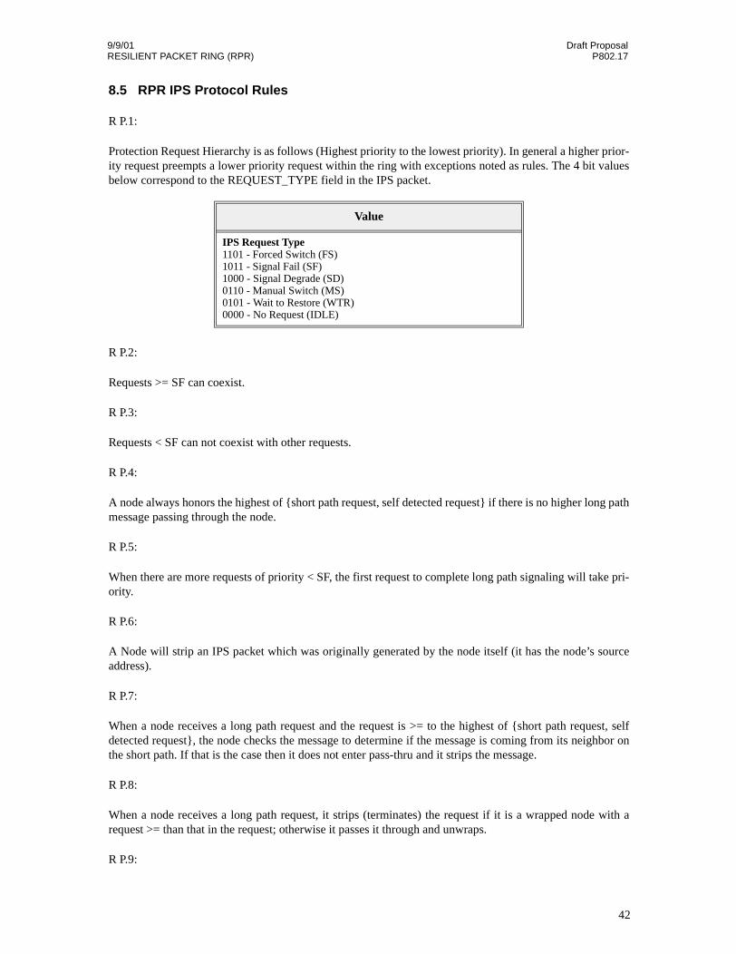
9/9/01 Draft ProposalRESILIENT PACKET RING (RPR) P802.17
8.5 RPR IPS Protocol Rules
R P.1:
Protection Request Hierarchy is as follows (Highest priority to the lowest priority). In general a higher prior-ity request preempts a lower priority request within the ring with exceptions noted as rules. The 4 bit valuesbelow correspond to the REQUEST_TYPE field in the IPS packet.
R P.2:
Requests >= SF can coexist.
R P.3:
Requests < SF can not coexist with other requests.
R P.4:
A node always honors the highest of {short path request, self detected request} if there is no higher long pathmessage passing through the node.
R P.5:
When there are more requests of priority < SF, the first request to complete long path signaling will take pri-ority.
R P.6:
A Node will strip an IPS packet which was originally generated by the node itself (it has the node’s sourceaddress).
R P.7:
When a node receives a long path request and the request is >= to the highest of {short path request, selfdetected request}, the node checks the message to determine if the message is coming from its neighbor onthe short path. If that is the case then it does not enter pass-thru and it strips the message.
R P.8:
When a node receives a long path request, it strips (terminates) the request if it is a wrapped node with arequest >= than that in the request; otherwise it passes it through and unwraps.
R P.9:
Value
IPS Request Type1101 - Forced Switch (FS)1011 - Signal Fail (SF)1000 - Signal Degrade (SD)0110 - Manual Switch (MS)0101 - Wait to Restore (WTR)0000 - No Request (IDLE)
42
9/9/01 Draft ProposalRESILIENT PACKET RING (RPR) P802.17
Each node keeps track of the addresses of the immediate neighbors (the neighbor node address is gleanedfrom the short path IPS messages).
R P.10:
When a wrapped node (which initially detected the failure) discovers disappearance of the failure, it entersWTR (user-configurable WTR time-period). WTR can be configured in the 10-600 sec. range with a defaultvalue of 60 sec.
R P.11:
When a node is in WTR mode, and detects that the new neighbor (as identified from the received short pathIPS message) is not the same as the old neighbor (stored at the time of wrap initiation), the node drops theWTR.
R P.12:
When a node is in WTR mode and long path request Source is not equal to the neighbor Id on the oppositeside (as stored at the time of wrap initiation), the node drops the WTR.
R P.13:
When a node receives a local protection request of type SD or SF and it cannot be executed (according toprotocol rules) it keeps the request pending. (The request can be kept pending outside of the protection pro-tocol implementation).
R P.14:
If a local non-failure request (WTR, MS, FS) clears and if there are no other requests pending, the nodeenters idle state.
R P.15:
If there are two failures and two resulting WTR conditions on a single span, the second WTR to time outbrings both the wraps down (after the WTR time expires a node does not unwrap automatically but waits tillit receives idle messages from its neighbor on the previously failed span)
R P.16:
If a short path FS request is present on a given side and a SF/SD condition takes place on the same side,accept and process the SF/SD condition ignoring the FS. Without this rule a single ended wrap conditioncould take place. (Wrap on one end of a span only).
R.P.17:
If a node receives an IPS message, it should update its topology accordingly and trigger a topology discov-ery process.
8.6 State Transitions
Figure 18 shows the simplified state transition diagram for the IPS protocol:
43
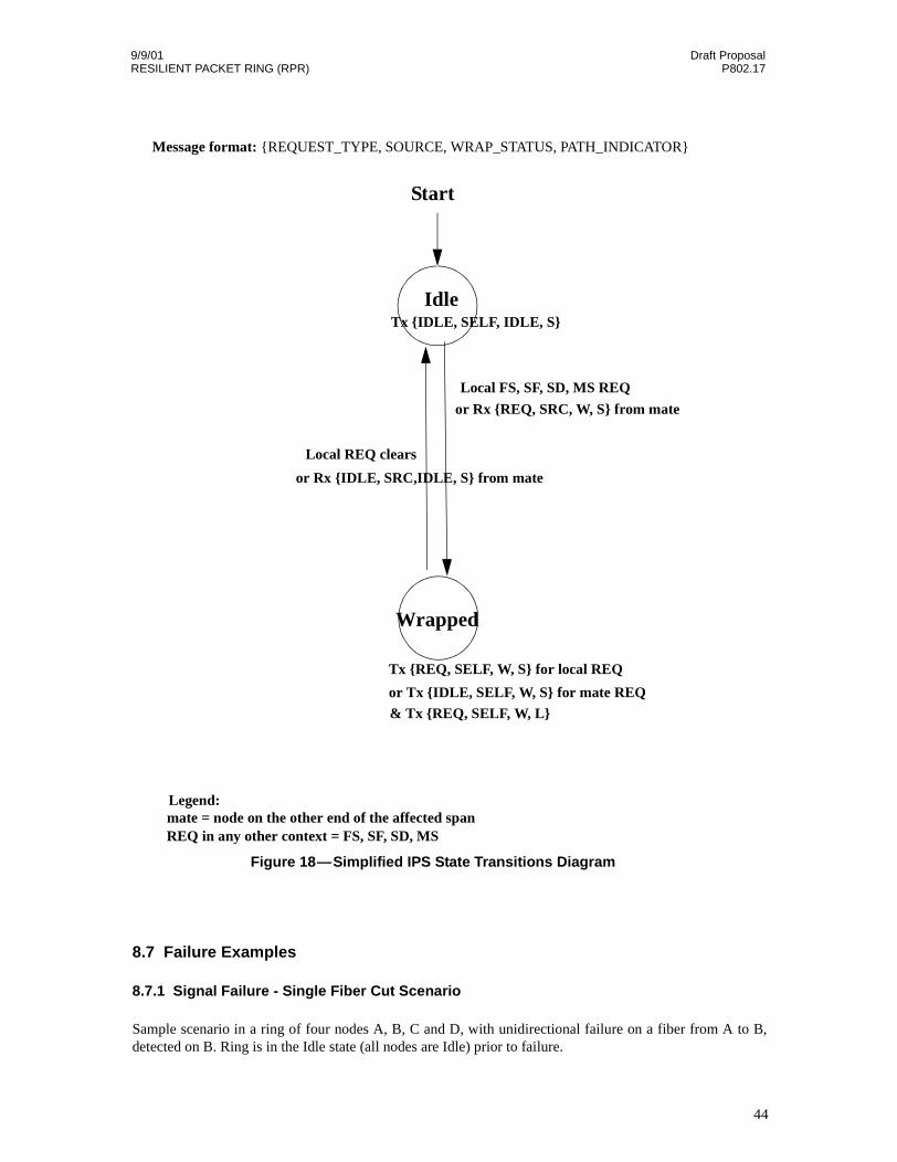
9/9/01 Draft ProposalRESILIENT PACKET RING (RPR) P802.17
8.7 Failure Examples
8.7.1 Signal Failure - Single Fiber Cut Scenario
Sample scenario in a ring of four nodes A, B, C and D, with unidirectional failure on a fiber from A to B,detected on B. Ring is in the Idle state (all nodes are Idle) prior to failure.
Idle
Wrapped
Start
Tx {IDLE, SELF, IDLE, S}
Local FS, SF, SD, MS REQ
Tx {REQ, SELF, W, S} for local REQ
& Tx {REQ, SELF, W, L}
Local REQ clears
or Rx {IDLE, SRC,IDLE, S} from mate
or Rx {REQ, SRC, W, S} from mate
or Tx {IDLE, SELF, W, S} for mate REQ
Message format: {REQUEST_TYPE, SOURCE, WRAP_STATUS, PATH_INDICATOR}
Legend:mate = node on the other end of the affected spanREQ in any other context = FS, SF, SD, MS
Figure 18—Simplified IPS State Transitions Diagram
44
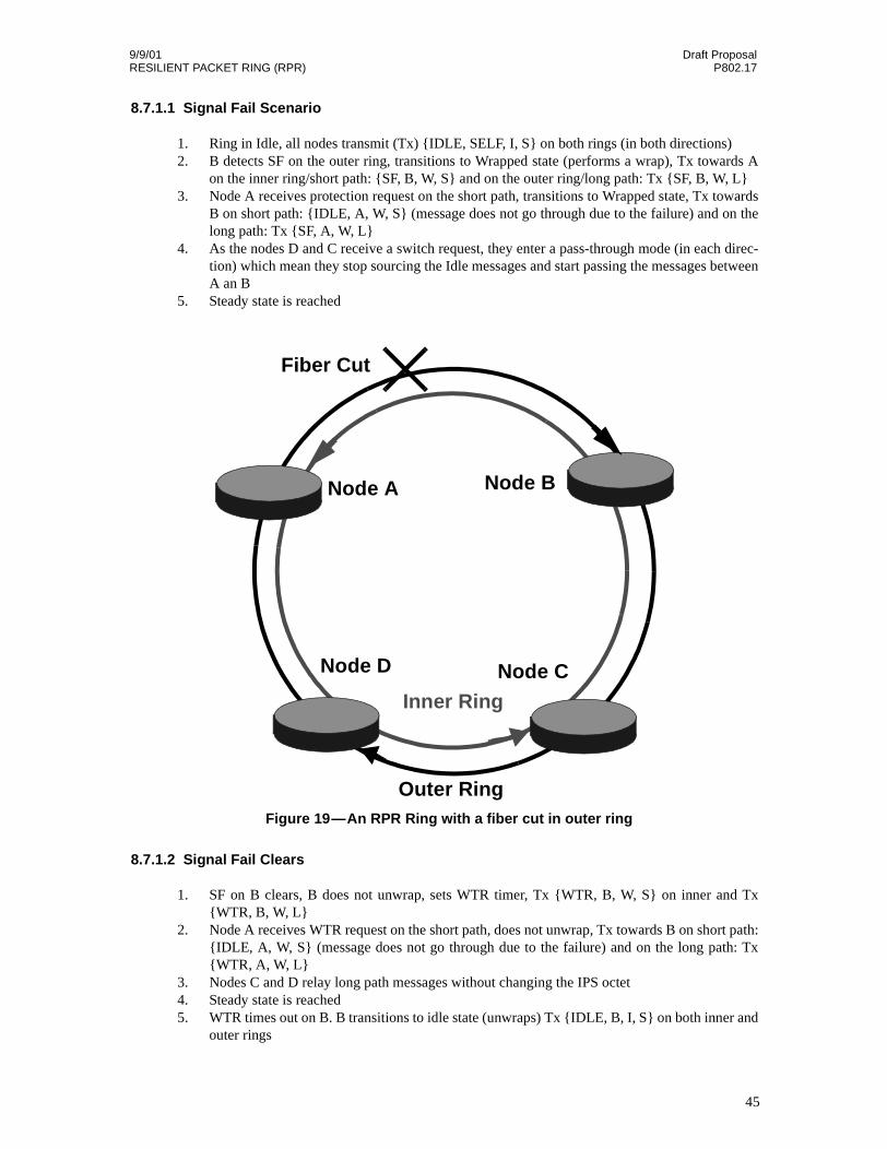
9/9/01 Draft ProposalRESILIENT PACKET RING (RPR) P802.17
8.7.1.1 Signal Fail Scenario
1. Ring in Idle, all nodes transmit (Tx) {IDLE, SELF, I, S} on both rings (in both directions)2. B detects SF on the outer ring, transitions to Wrapped state (performs a wrap), Tx towards A
on the inner ring/short path: {SF, B, W, S} and on the outer ring/long path: Tx {SF, B, W, L}3. Node A receives protection request on the short path, transitions to Wrapped state, Tx towards
B on short path: {IDLE, A, W, S} (message does not go through due to the failure) and on thelong path: Tx {SF, A, W, L}
4. As the nodes D and C receive a switch request, they enter a pass-through mode (in each direc-tion) which mean they stop sourcing the Idle messages and start passing the messages betweenA an B
5. Steady state is reached
8.7.1.2 Signal Fail Clears
1. SF on B clears, B does not unwrap, sets WTR timer, Tx {WTR, B, W, S} on inner and Tx{WTR, B, W, L}
2. Node A receives WTR request on the short path, does not unwrap, Tx towards B on short path:{IDLE, A, W, S} (message does not go through due to the failure) and on the long path: Tx{WTR, A, W, L}
3. Nodes C and D relay long path messages without changing the IPS octet4. Steady state is reached5. WTR times out on B. B transitions to idle state (unwraps) Tx {IDLE, B, I, S} on both inner and
outer rings
Inner Ring
Outer Ring
Fiber Cut
Node A Node B
Node D Node C
Figure 19—An RPR Ring with a fiber cut in outer ring
45
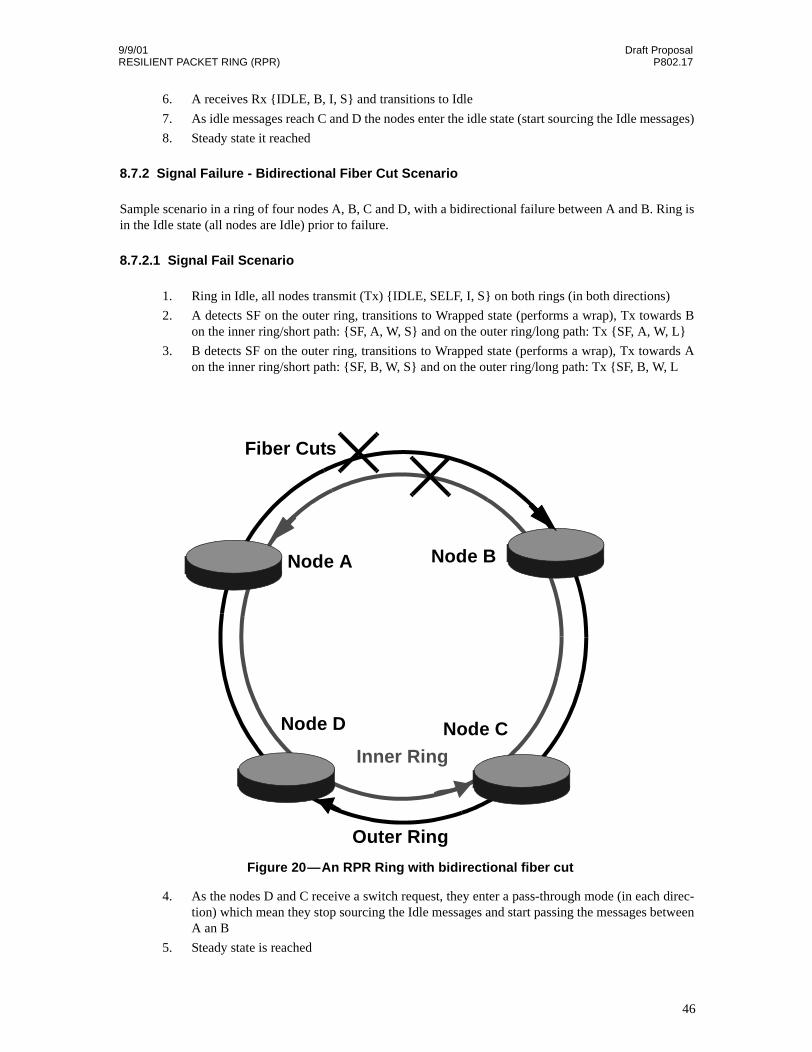
9/9/01 Draft ProposalRESILIENT PACKET RING (RPR) P802.17
6. A receives Rx {IDLE, B, I, S} and transitions to Idle
7. As idle messages reach C and D the nodes enter the idle state (start sourcing the Idle messages)
8. Steady state it reached
8.7.2 Signal Failure - Bidirectional Fiber Cut Scenario
Sample scenario in a ring of four nodes A, B, C and D, with a bidirectional failure between A and B. Ring isin the Idle state (all nodes are Idle) prior to failure.
8.7.2.1 Signal Fail Scenario
1. Ring in Idle, all nodes transmit (Tx) {IDLE, SELF, I, S} on both rings (in both directions)
2. A detects SF on the outer ring, transitions to Wrapped state (performs a wrap), Tx towards Bon the inner ring/short path: {SF, A, W, S} and on the outer ring/long path: Tx {SF, A, W, L}
3. B detects SF on the outer ring, transitions to Wrapped state (performs a wrap), Tx towards Aon the inner ring/short path: {SF, B, W, S} and on the outer ring/long path: Tx {SF, B, W, L
4. As the nodes D and C receive a switch request, they enter a pass-through mode (in each direc-tion) which mean they stop sourcing the Idle messages and start passing the messages betweenA an B
5. Steady state is reached
Inner Ring
Outer Ring
Fiber Cuts
Node A Node B
Node D Node C
Figure 20—An RPR Ring with bidirectional fiber cut
46
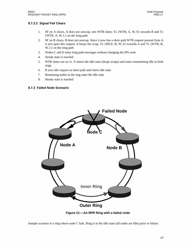
9/9/01 Draft ProposalRESILIENT PACKET RING (RPR) P802.17
8.7.2.2 Signal Fail Clears
1. SF on A clears, A does not unwrap, sets WTR timer, Tx {WTR, A, W, S} towards B and Tx{WTR, A, W, L} on the long path
2. SF on B clears, B does not unwrap. Since it now has a short path WTR request present from Ait acts upon this request. It keeps the wrap, Tx {IDLE, B, W, S} towards A and Tx {WTR, B,W, L} on the long path
3. Nodes C and D relay long path messages without changing the IPS octet
4. Steady state is reached
5. WTR times out on A. A enters the idle state (drops wraps) and starts transmitting idle in bothrings
6. B sees idle request on short path and enters idle state
7. Remaining nodes in the ring enter the idle state
8. Steady state is reached
8.7.3 Failed Node Scenario
Sample scenario in a ring where node C fails. Ring is in the Idle state (all nodes are Idle) prior to failure.
Inner Ring
Outer Ring
Failed Node
Node A
Node C
Node B
Figure 21—An RPR Ring with a failed node
47
9/9/01 Draft ProposalRESILIENT PACKET RING (RPR) P802.17
8.7.3.1 Node Failure (or fiber cuts on both sides of the node)
1. Ring in Idle, all nodes transmit (Tx) {IDLE, SELF, I, S} on both rings (in both directions)2. Based on the source field of the idle messages, all nodes identify the neighbors and keep track
of them3. B detects SF on the outer ring, transitions to Wrapped state (performs a wrap), Tx towards C
on the inner ring/short path: {SF, B, W, S} and on the outer ring/long path: Tx {SF, B, W, L}4. A detects SF on the inner ring, transitions to Wrapped state (performs a wrap), Tx towards C
on the outer ring/short path: {SF, A, W, S} and on the inner ring/long path: Tx {SF, A, W, L}5. As the nodes on the long path between A and B receive a SF request, they enter a pass-through
mode (in each direction), stop sourcing the Idle messages and start passing the messagesbetween A an B
6. Steady state is reached
8.7.3.2 Failed Node and One Span Return to Service
Note: Practically the node will always return to service with one span coming after the other (withthe time delta potentially close to 0). Here, a node is powered up with the fibers connected andfault free.
1. Node C and a span between A and C return to service (SF between A and C disappears)2. Node C, not seeing any faults starts to source idle messages {IDLE, C, I, S} in both directions.3. Fault disappears on A and A enters a WTR (briefly)4. Node A receives idle message from node C. Because the long path protection request {SF, B,
W, L} received over the long span is not originating from the short path neighbor (C), node Adrops the WTR and enters a PassThrough state passing requests between C and B
5. Steady state is reached
8.7.3.3 Second Span Returns to Service
The scenario is like the Bidirectional Fiber Cut fault clearing scenario.
48

9/9/01 Draft ProposalRESILIENT PACKET RING (RPR) P802.17
Sample scenario in a ring where initially nodes A and B are connected. Subsequently fibers between thenodes A and B are disconnected and a new node C is inserted.
8.7.3.4 Bidirectional Fiber Cut
1. Ring in Idle, all nodes transmit (Tx) {IDLE, SELF, I, S} on both rings (in both directions)
2. Fibers are removed between nodes A and B
3. B detects SF on the outer ring, transitions to Wrapped state (performs a wrap), Tx towards Aon the inner ring/short path: {SF, B, W, S} and on the outer ring/long path: Tx {SF, B, W, L}
4. A detects SF on the inner ring, transitions to Wrapped state (performs a wrap), Tx towards Bon the inner ring/short path: {SF, A, W, S} and on the outer ring/long path: Tx {SF, A, W, L}
5. As the nodes on the long path between A and B receive a SF request, they enter a pass-throughmode (in each direction), stop sourcing the Idle messages and start passing the messagesbetween A an B
6. Steady state is reached
8.7.3.5 Node C is Powered Up and Fibers Between Nodes A and C are Reconnected
This scenario is identical to the returning a Failed Node to Service scenario.
Figure 22—An RPR Ring with a failed node
Inner Ring
Outer Ring
Added Node
Node A
Node C
Node B
49

9/9/01 Draft ProposalRESILIENT PACKET RING (RPR) P802.17
8.7.3.6 Second Span Put Into Service
Nodes C and B are connected. The scenario is identical to Bidirectional Fiber Cut fault clearing scenario.
50
9/9/01 Draft ProposalRESILIENT PACKET RING (RPR) P802.17
9. Physical Media
RPR is media independent.RPR Frame will be allowed to send over different physical media.
9.1 SONET/SDH Network
RPR may also connect to a SONET/SDH ring network via a tributary connection to a SONET/SDH ADM(Add Drop Multiplexor). The two RPR rings may be mapped into two STS-Nc connections. SONET/SDHnetworks typically provide fully redundant connections, so RPR mapped into two STS-Nc connections willhave two levels of protection. The SONET/SDH network provides layer 1 protection, and RPR provideslayer 2 protection. In this case it is recommended to hold off the RPR Signal Fail IPS triggers (which corre-spond to failures which can be protected by SONET/SDH) for about 100 msec in order to allow theSONET/SDH network to protect. Only if a failure persists for over 100 msec (indicating SONET/SDH pro-tection failure) should the IPS protection take place.
Since multiple protection levels over the same physical infrastructure are not very desirable, an alternateway of connecting RPR over a SONET/SDH network is configuring SONET/SDH without protection. Sincethe connection is unprotected at layer 1, RPR would be the sole protection mechanism.
Hybrid RPR rings may also be built where some parts of the ring traverse over a SONET/SDH networkwhile other parts do not.
Connections to a SONET/SDH network would have to be synchronized to network timing by some means.This can be accomplished by locking the transmit connection to the frequency of the receive connection(called loop timing) or via an external synchronization technique.
Connections made via dark fiber or over a WDM optical network should utilize internal timing as clock syn-chronization is not necessary in this case.
9.1.1 POS Framing
Flag delimiting on SONET/SDH uses the octet stuffing method defined for POS. The packet delimiter flags (0x7E) arerequired for SONET/SDH links but may not be necessary for RPR on other media types. An End-of-Packet is delineatedby a flag, which might also be the next packet’s starting flag. If the data appears to be a flag (0x7E) or an escape charac-ter (0x7D) anywhere inside of a packet, the data must be marked with an escape character.
SONET/SDH framing plus POS packet delimiting allows RPR to be used directly over fiber or through anoptical network (including WDM equipment).
9.1.2 GFP Framing
RPR frame will be able to encapsulate using the GFP frame format
9.2 Ethernet
RPR frames can be sent over Ethernet physical media.
51

9/9/01 Draft ProposalRESILIENT PACKET RING (RPR) P802.17
10. Pass-thru mode
An optional mode of operation is pass-thru mode. In pass-thru mode, a node transparently forwards data.The node does not source packets, and does not modify any of the packets that it forwards. Data should con-tinue to be sorted into high and low priority transit buffers with high priority transit buffers always emptiedfirst. The node does not source any control packets (e.g. topology discovery or IPS) and basically looks likea signal regenerator with delay (caused by packets that happened to be in the transit buffer when the transi-tion to pass-thru mode occurred). A node can enter pass-thru mode because of an operator command or dueto a error condition such as a software crash.
52

9/9/01 Draft ProposalRESILIENT PACKET RING (RPR) P802.17
11. References
[1] ANSI X3T9 FDDI Specification
[2] IEEE 802.5 Token Ring Specification
[3] Bellcore GR-1230, Issue 4, Dec. 1998, "SONET Bidirectional Line-Switched Ring Equipment GenericCriteria".
[4] ANSI T1.105.01-1998 "Synchronous Optical Network (SONET) Automatic Protection Switching"
[5] Malis, A. and W. Simpson, "PPP over SONET/SDH", RFC 2615, June 1999.
[6] Simpson, W., "PPP in HDLC-like Framing", STD 51, RFC 1662, July 1994.
53

9/9/01 Draft ProposalRESILIENT PACKET RING (RPR) P802.17
54