Embed Size (px)
Citation preview
Dr Simin NasseriDr Simin NasseriSouthern Polytechnic State UniversitySouthern Polytechnic State University
1
Copyright © The McGraw-Hill Companies, Inc. Permission required for reproduction or display.
Chapter 7
Engineering Graphics IDr Simin Nasseri
Southern Polytechnic State University
Dr Simin NasseriDr Simin NasseriSouthern Polytechnic State UniversitySouthern Polytechnic State University
2
1. Sketching is an important method of quickly communicating design ideas.
2. Sketching is a way of thinking as it is a method of recording ideas and communicating to others.
3. Most new designs are first recorded using design sketches.
Dr Simin NasseriDr Simin NasseriSouthern Polytechnic State UniversitySouthern Polytechnic State University
3
Figure 7.1
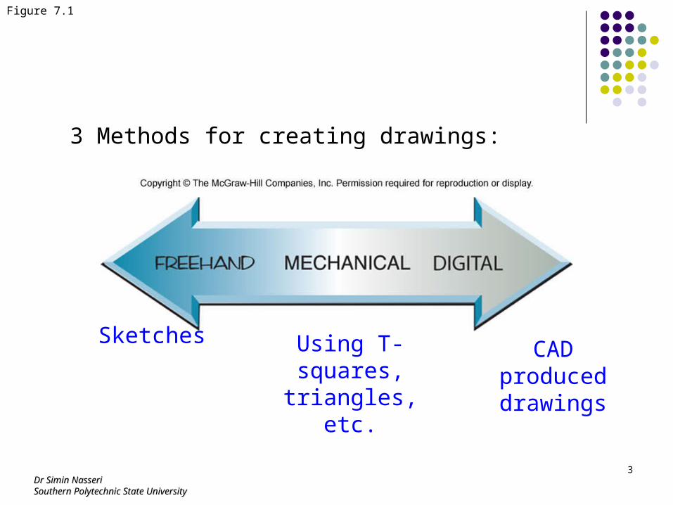
3 Methods for creating drawings:
Sketches Using T-squares,
triangles, etc.
CAD produced drawings
Dr Simin NasseriDr Simin NasseriSouthern Polytechnic State UniversitySouthern Polytechnic State University
4
Figure 7.3
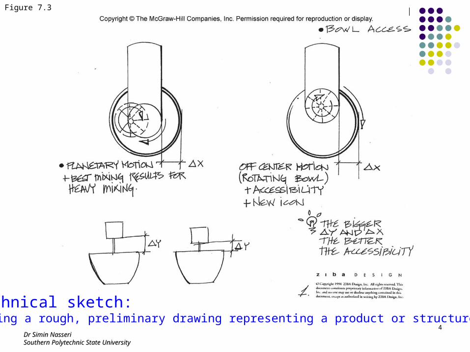
A technical sketch:Producing a rough, preliminary drawing representing a product or structure.
Dr Simin NasseriDr Simin NasseriSouthern Polytechnic State UniversitySouthern Polytechnic State University
5
Figure 7.26
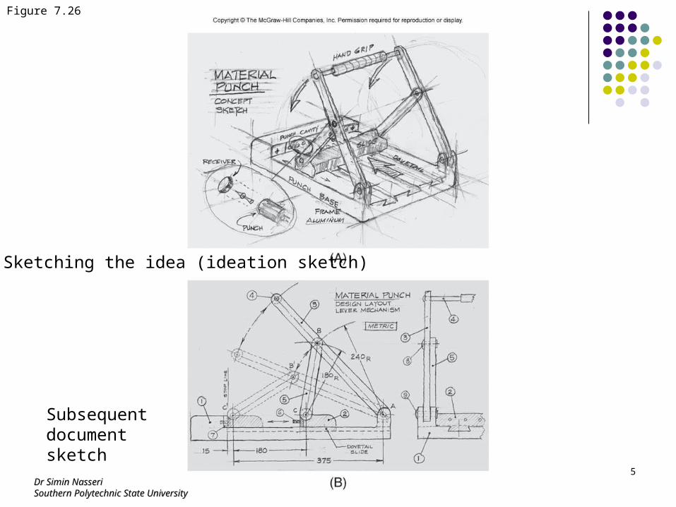
Sketching the idea (ideation sketch)
Subsequent document sketch
Dr Simin NasseriDr Simin NasseriSouthern Polytechnic State UniversitySouthern Polytechnic State University
6
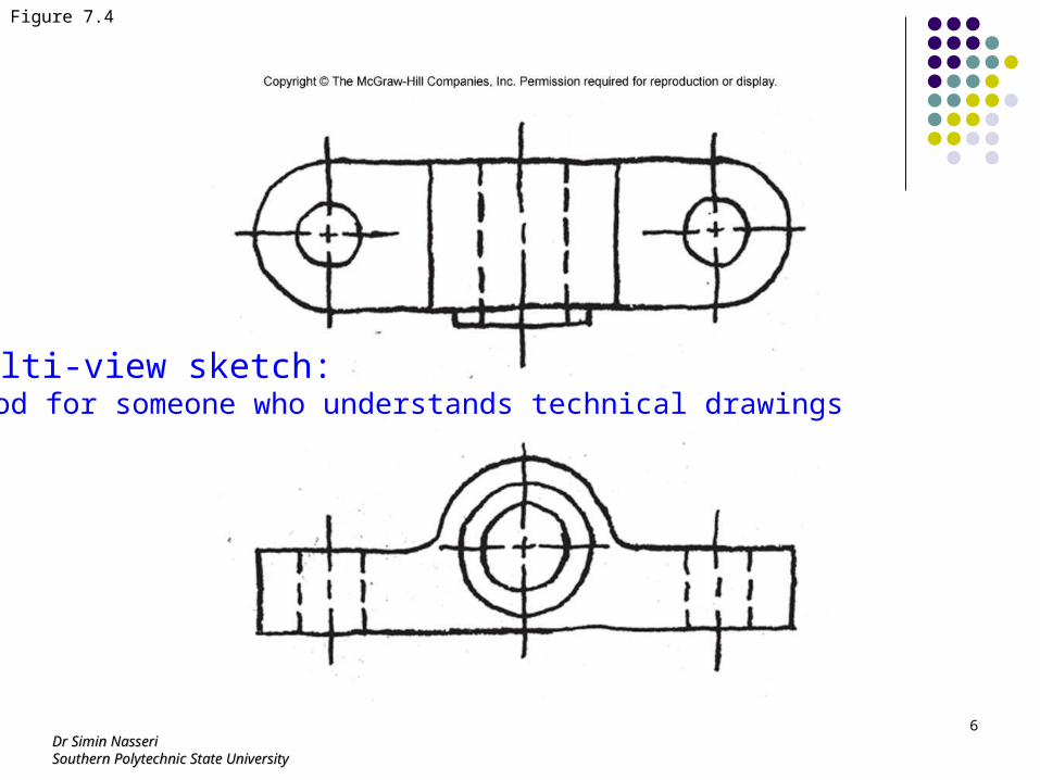
Figure 7.4
Multi-view sketch:Good for someone who understands technical drawings
Dr Simin NasseriDr Simin NasseriSouthern Polytechnic State UniversitySouthern Polytechnic State University
7
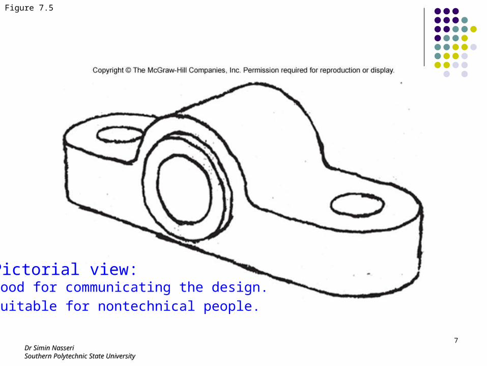
Figure 7.5
Pictorial view:Good for communicating the design.
Suitable for nontechnical people.
Dr Simin NasseriDr Simin NasseriSouthern Polytechnic State UniversitySouthern Polytechnic State University
8
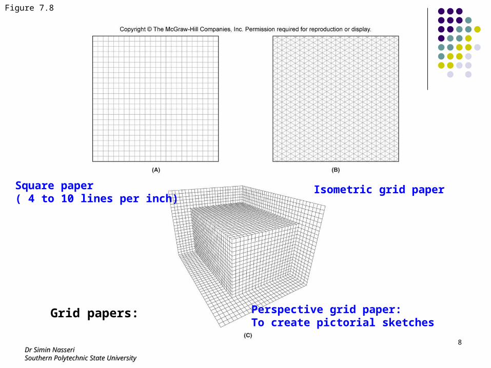
Figure 7.8
Grid papers:
Square paper ( 4 to 10 lines per inch)
Isometric grid paper
Perspective grid paper:To create pictorial sketches
Dr Simin NasseriDr Simin NasseriSouthern Polytechnic State UniversitySouthern Polytechnic State University
9
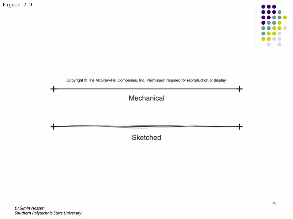
Figure 7.9
Dr Simin NasseriDr Simin NasseriSouthern Polytechnic State UniversitySouthern Polytechnic State University
10
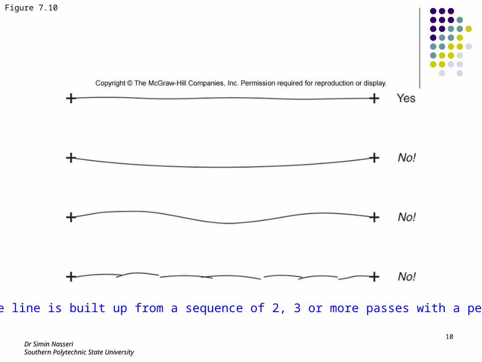
Figure 7.10
The line is built up from a sequence of 2, 3 or more passes with a pencil.
Dr Simin NasseriDr Simin NasseriSouthern Polytechnic State UniversitySouthern Polytechnic State University
11
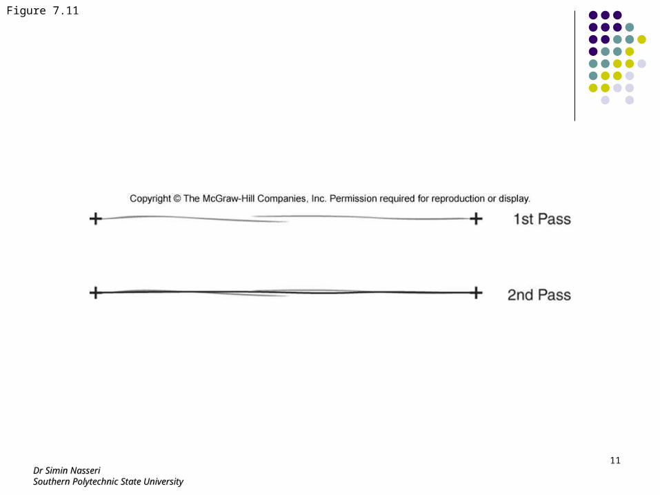
Figure 7.11
Dr Simin NasseriDr Simin NasseriSouthern Polytechnic State UniversitySouthern Polytechnic State University
12
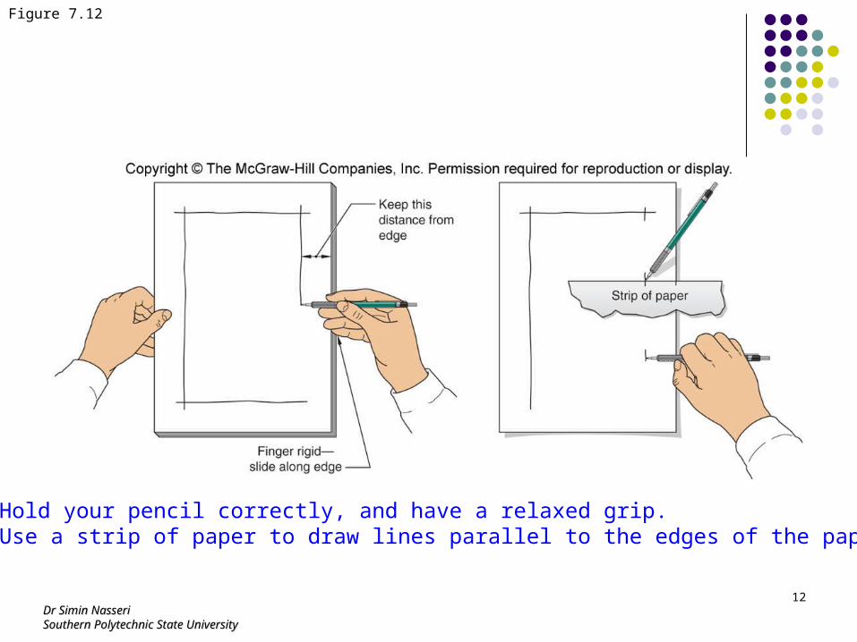
Figure 7.12
Hold your pencil correctly, and have a relaxed grip.Use a strip of paper to draw lines parallel to the edges of the paper.
Dr Simin NasseriDr Simin NasseriSouthern Polytechnic State UniversitySouthern Polytechnic State University
13
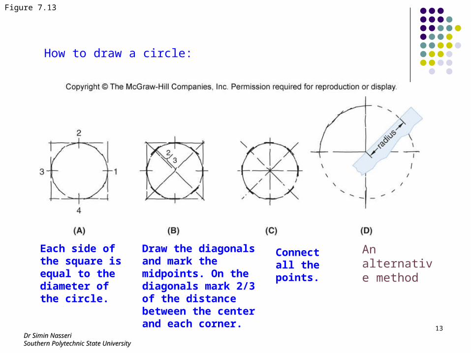
Figure 7.13
How to draw a circle:
Each side of the square is equal to the diameter of the circle.
Draw the diagonals and mark the midpoints. On the diagonals mark 2/3 of the distance between the center and each corner.
Connect all the points.
An alternative method
Dr Simin NasseriDr Simin NasseriSouthern Polytechnic State UniversitySouthern Polytechnic State University
14
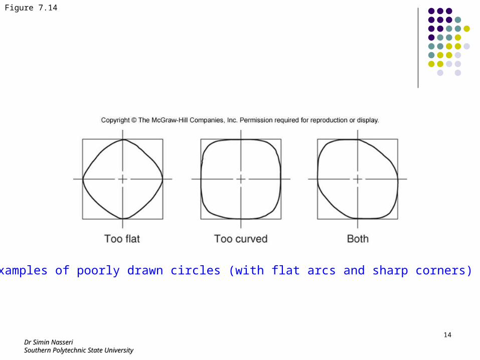
Figure 7.14
Examples of poorly drawn circles (with flat arcs and sharp corners)
Dr Simin NasseriDr Simin NasseriSouthern Polytechnic State UniversitySouthern Polytechnic State University
15
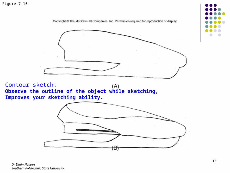
Figure 7.15
Contour sketch:Observe the outline of the object while sketching,Improves your sketching ability.
Dr Simin NasseriDr Simin NasseriSouthern Polytechnic State UniversitySouthern Polytechnic State University
16
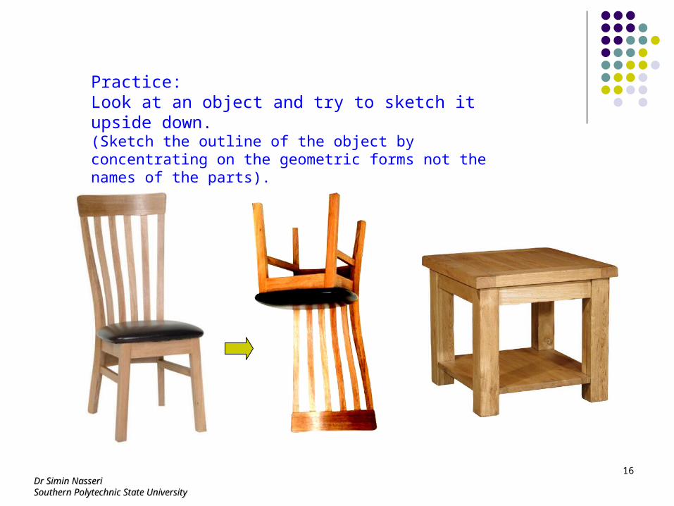
Practice:Look at an object and try to sketch it upside down.(Sketch the outline of the object by concentrating on the geometric forms not the names of the parts).
Dr Simin NasseriDr Simin NasseriSouthern Polytechnic State UniversitySouthern Polytechnic State University
17
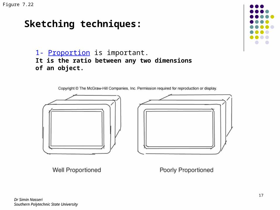
Sketching techniques:
1- Proportion is important. It is the ratio between any two dimensions of an object.
Figure 7.22
Dr Simin NasseriDr Simin NasseriSouthern Polytechnic State UniversitySouthern Polytechnic State University
18
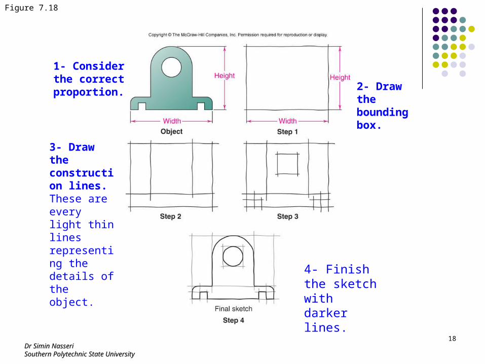
Figure 7.18
2- Draw the bounding box.
1- Consider the correct proportion.
3- Draw the construction lines.These are every light thin lines representing the details of the object.
4- Finish the sketch with darker lines.
Dr Simin NasseriDr Simin NasseriSouthern Polytechnic State UniversitySouthern Polytechnic State University
19
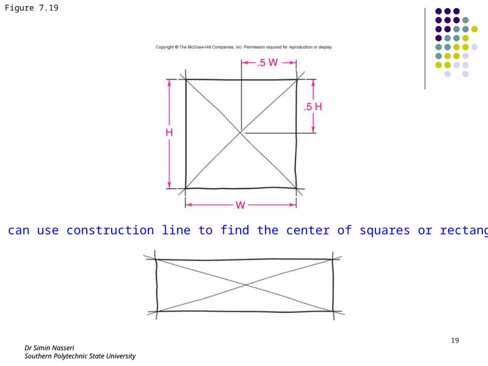
Figure 7.19
You can use construction line to find the center of squares or rectangles.
Dr Simin NasseriDr Simin NasseriSouthern Polytechnic State UniversitySouthern Polytechnic State University
20
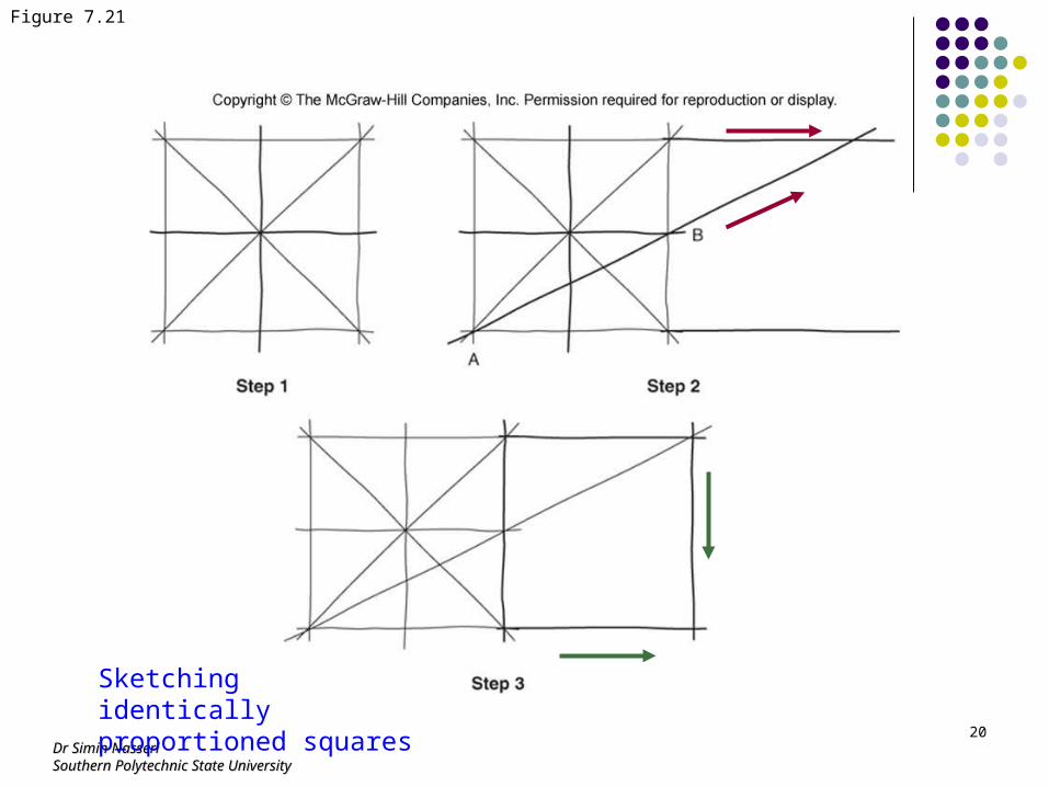
Figure 7.21
Sketching identically proportioned squares
Dr Simin NasseriDr Simin NasseriSouthern Polytechnic State UniversitySouthern Polytechnic State University
21
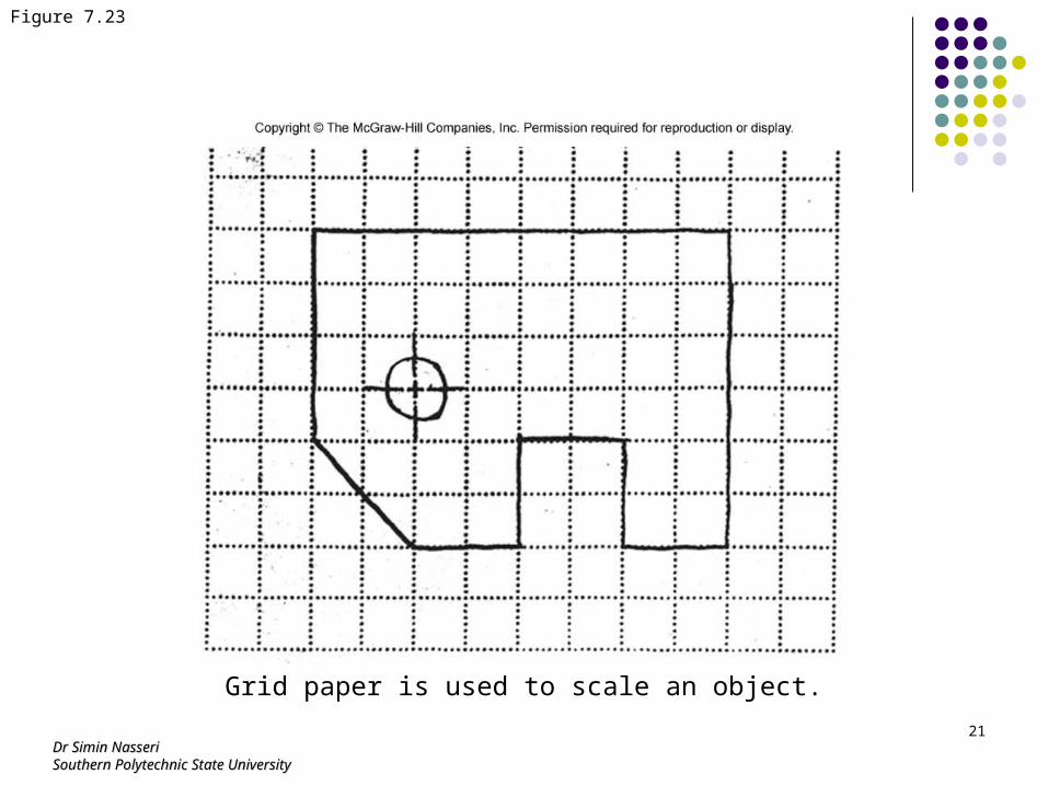
Figure 7.23
Grid paper is used to scale an object.
Dr Simin NasseriDr Simin NasseriSouthern Polytechnic State UniversitySouthern Polytechnic State University
22
Figure 7.24
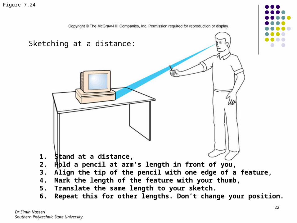
Sketching at a distance:
1. Stand at a distance,2. Hold a pencil at arm’s length in front of you,3. Align the tip of the pencil with one edge of a feature,4. Mark the length of the feature with your thumb,5. Translate the same length to your sketch.6. Repeat this for other lengths. Don’t change your position.
Dr Simin NasseriDr Simin NasseriSouthern Polytechnic State UniversitySouthern Polytechnic State University
23
Figure 7.28
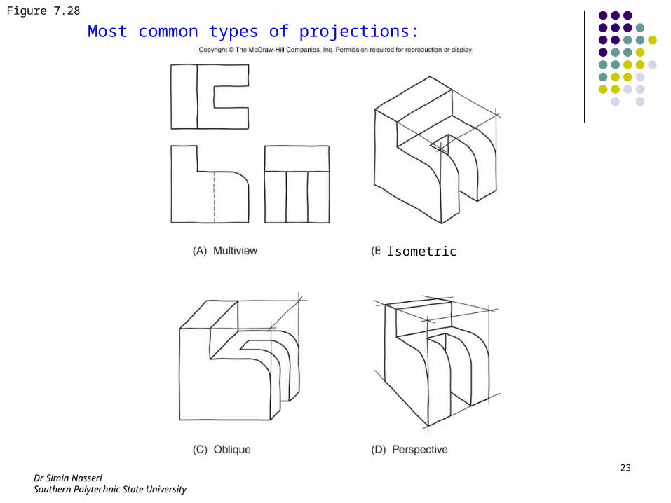
Most common types of projections:
Isometric
Dr Simin NasseriDr Simin NasseriSouthern Polytechnic State UniversitySouthern Polytechnic State University
24
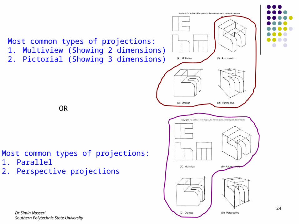
Most common types of projections:1. Multiview (Showing 2 dimensions)2. Pictorial (Showing 3 dimensions)
OR
Most common types of projections:1. Parallel2. Perspective projections
Dr Simin NasseriDr Simin NasseriSouthern Polytechnic State UniversitySouthern Polytechnic State University
25
Figure 7.29
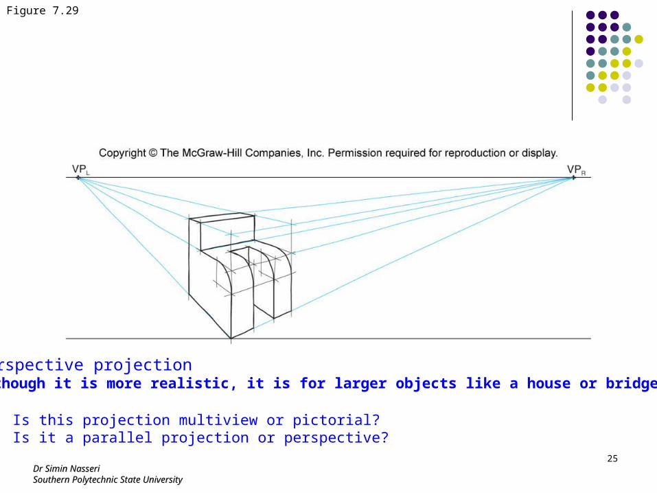
Perspective projectionAlthough it is more realistic, it is for larger objects like a house or bridge.
Is this projection multiview or pictorial?Is it a parallel projection or perspective?
Dr Simin NasseriDr Simin NasseriSouthern Polytechnic State UniversitySouthern Polytechnic State University
26
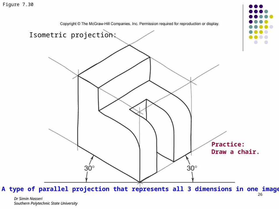
Figure 7.30
Isometric projection:
A type of parallel projection that represents all 3 dimensions in one image.
Practice:Draw a chair.
Dr Simin NasseriDr Simin NasseriSouthern Polytechnic State UniversitySouthern Polytechnic State University
27
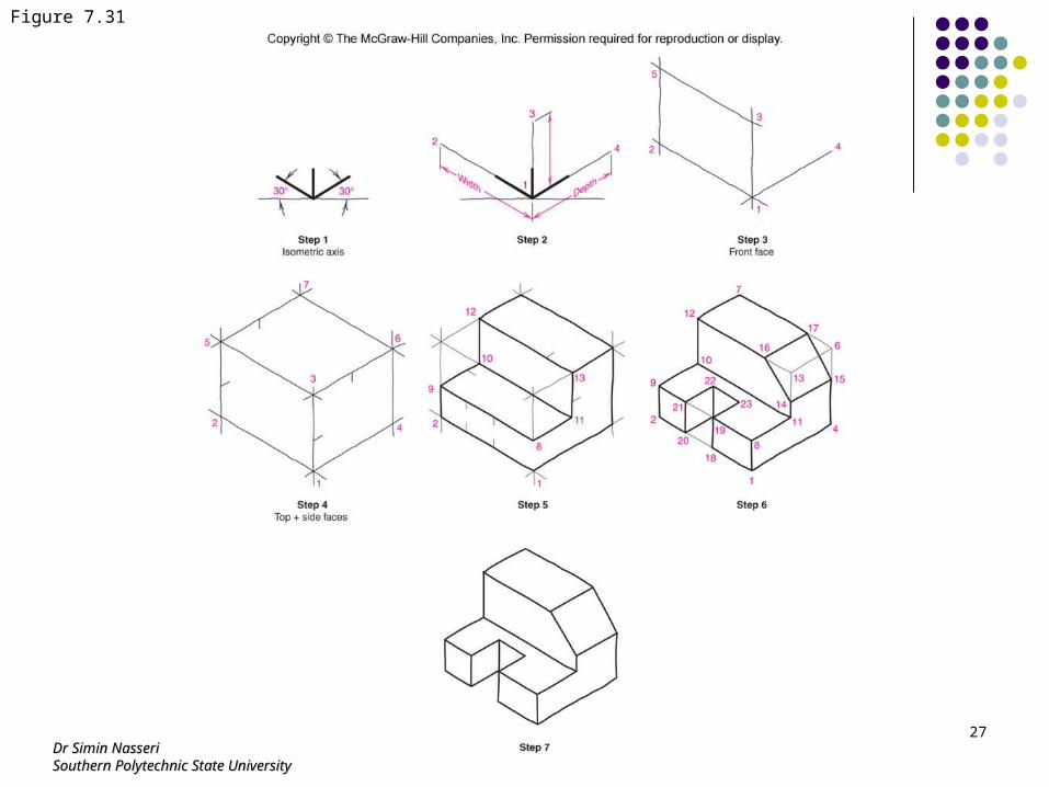
Figure 7.31
Dr Simin NasseriDr Simin NasseriSouthern Polytechnic State UniversitySouthern Polytechnic State University
28
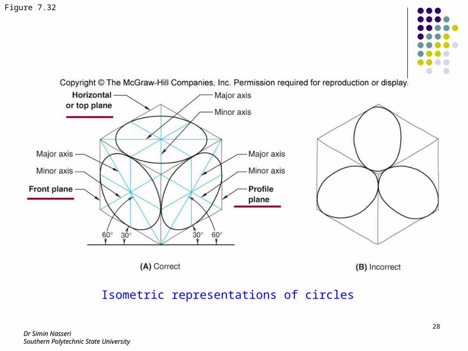
Figure 7.32
Isometric representations of circles
Dr Simin NasseriDr Simin NasseriSouthern Polytechnic State UniversitySouthern Polytechnic State University
29
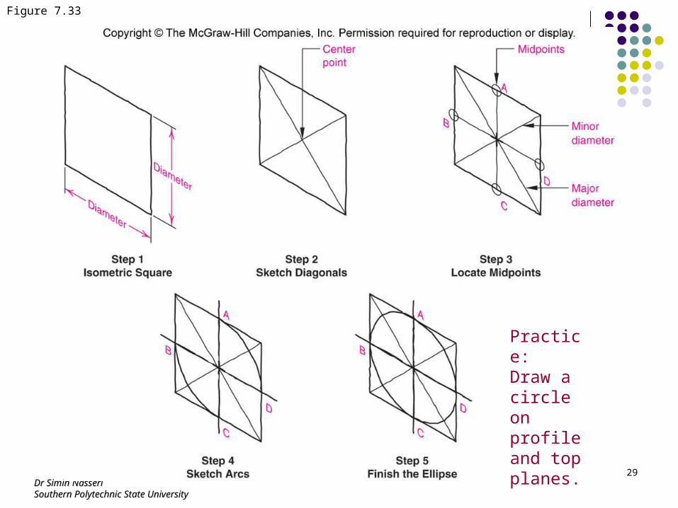
Figure 7.33
Practice:Draw a circle on profile and top planes.
Dr Simin NasseriDr Simin NasseriSouthern Polytechnic State UniversitySouthern Polytechnic State University
30
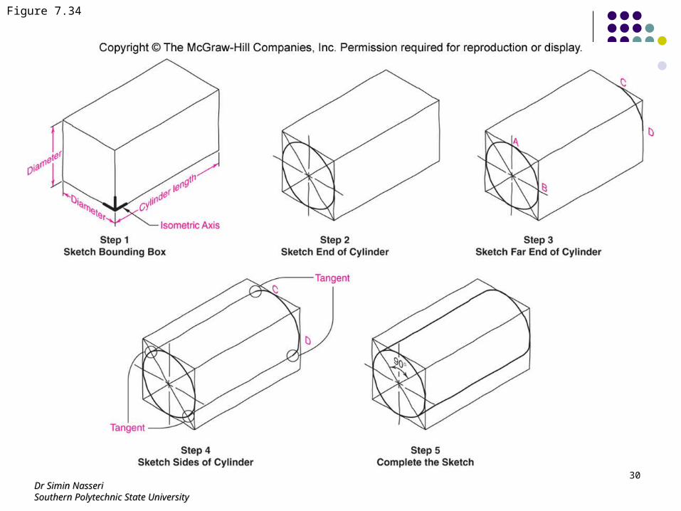
Figure 7.34
Dr Simin NasseriDr Simin NasseriSouthern Polytechnic State UniversitySouthern Polytechnic State University
31
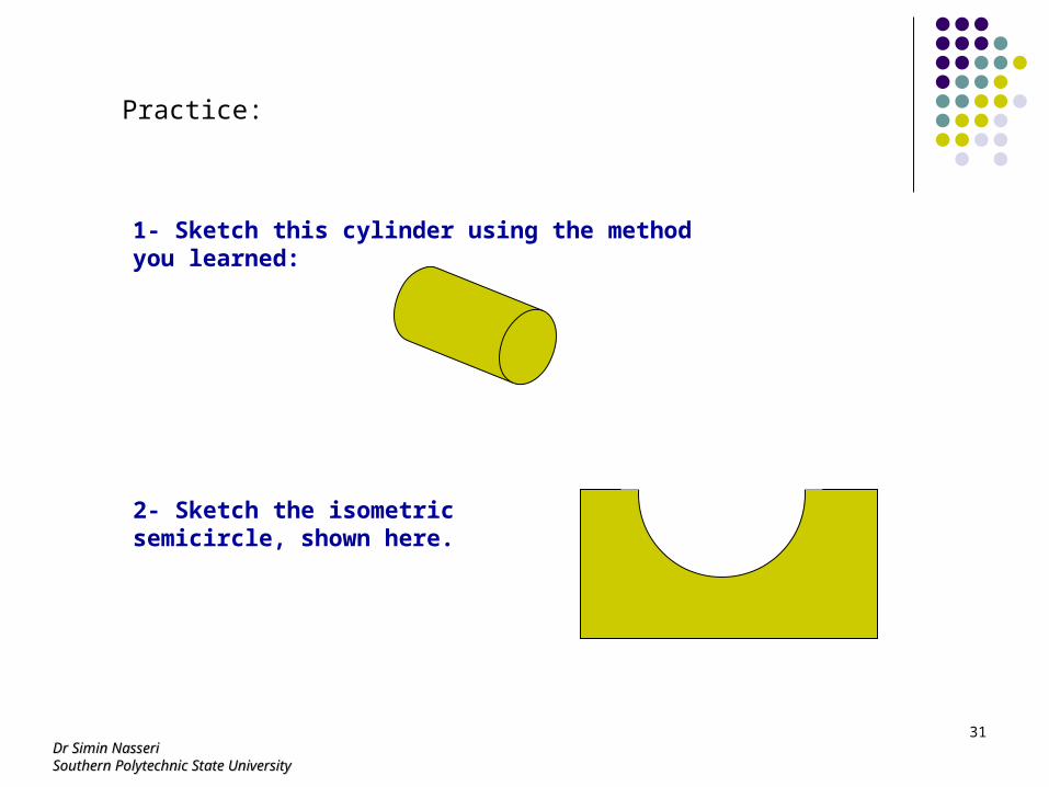
Practice:
2- Sketch the isometric semicircle, shown here.
1- Sketch this cylinder using the method you learned:
Dr Simin NasseriDr Simin NasseriSouthern Polytechnic State UniversitySouthern Polytechnic State University
32
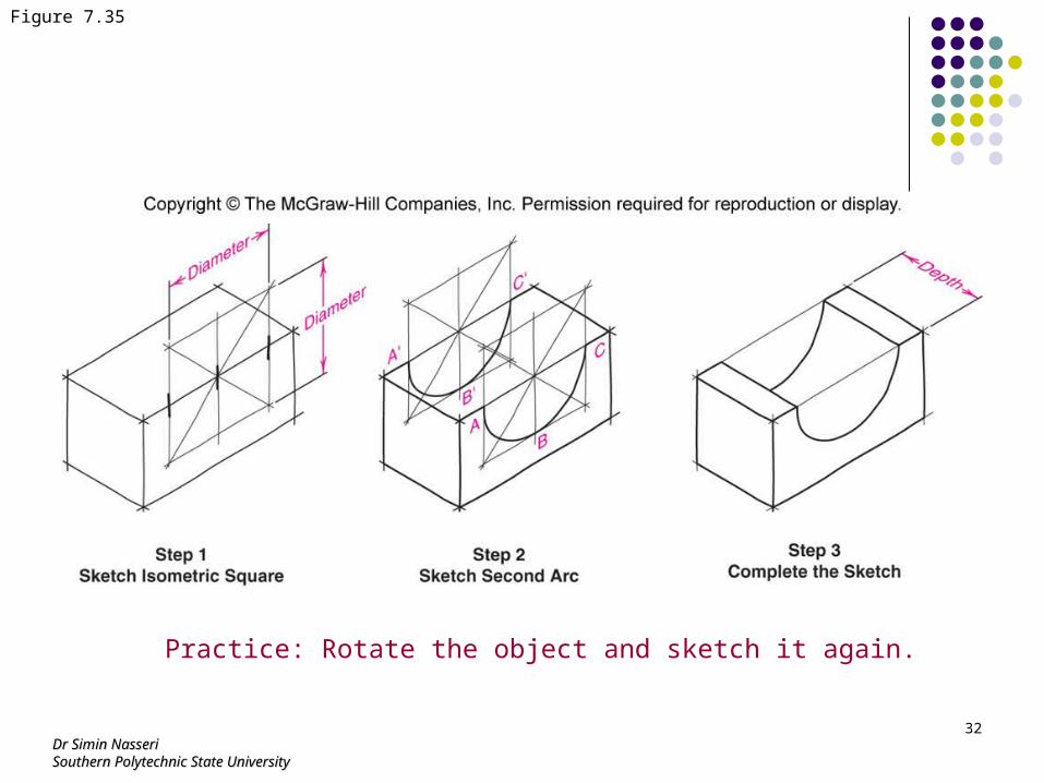
Figure 7.35
Practice: Rotate the object and sketch it again.
Dr Simin NasseriDr Simin NasseriSouthern Polytechnic State UniversitySouthern Polytechnic State University
33
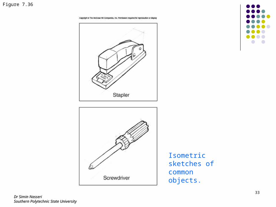
Figure 7.36
Isometric sketches of common objects.
Dr Simin NasseriDr Simin NasseriSouthern Polytechnic State UniversitySouthern Polytechnic State University
34
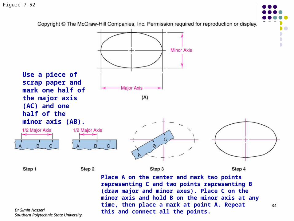
Figure 7.52
Use a piece of scrap paper and mark one half of the major axis (AC) and one half of the minor axis (AB).
Place A on the center and mark two points representing C and two points representing B (draw major and minor axes). Place C on the minor axis and hold B on the minor axis at any time, then place a mark at point A. Repeat this and connect all the points.