Embed Size (px)
Citation preview
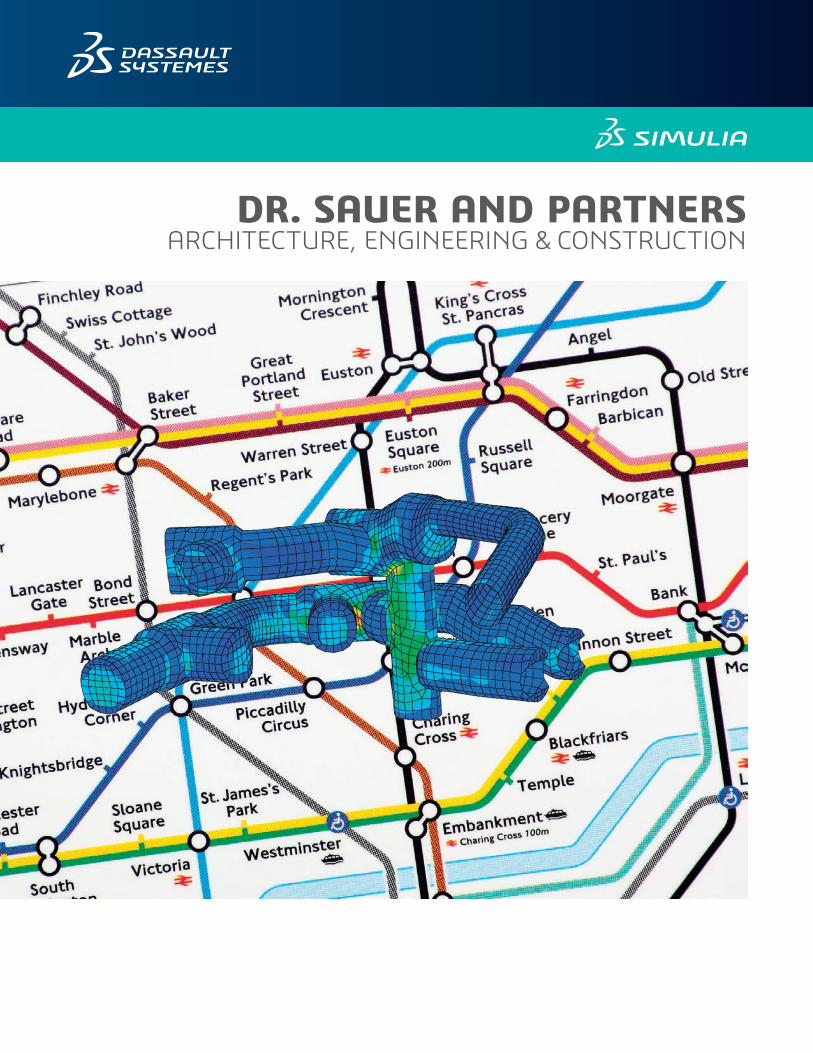
DR. SAUER AND PARTNERSARCHITECTURE, ENGINEERING & CONSTRUCTION
As population pressures in metropolitan areas rise, major world cities often respond with expanding networks of trains to promote more efficient travel. The London Underground is no exception: it now serves Greater London and surrounding counties with 270 stations and 250 miles of track. Some 1.23 billion passengers were carried in and out of the region in 2012/2013.
At the geographic heart of this system are the world’s first underground railway tunnels, opened in 1863 and built just below the surface of metropolitan London using the cut and cover method. Later, circular tunnels—giving rise to the nickname the Tube—were dug through the London Clay at a deeper level.
Now celebrating 150 years of operations, the Underground is still growing: The current Bond Street Station Upgrade (BSSU) project, slated for completion in 2018, has been dubbed “one of the most complex tunneling projects in the U.K.” As London’s future Crossrail line intersects with the Bond Street Station, passenger numbers in the expanded interchange are expected to rise from 155,000 to 225,000 daily.
Much of what makes the BSSU so complex is all the construction that is already there. The station is located in London’s busiest shopping district, the West End, and comprises a complex web of train tunnels, pedestrian walkways and escalators that include connections to the Jubilee and Central lines. “The new tunnels are located in close proximity to so many existing ones,” says Dr. Ali Nasekhian, senior tunnel/geotechnical engineer with Dr. Sauer and Partners, London, the firm providing tunneling expertise to the project. “As a result, the design challenges we faced included complex tunnel
geometry and alignment, limited clearance to existing building foundation, restricted worksite and strict settlement criteria.”
Dr. Sauer and Partners have been designing railway and road tunnels for over 30 years. In 2010 the company was subcontracted to a joint venture of Halcrow and Atkins (the main contractor is a Costain Laing O’Rourke JV), and has responsibility for preliminary-to-detailed design and construction on all BSSU sprayed concrete lined (SCL) tunnels. These include two
Challenge:As the firm providing tunneling expertise to the London Underground, Dr. Sauer and Partners faced complex design challenges that included tunnel geometry and alignment, limited clearance to existing foundations, a restricted worksite and strict settlement criteria.
Solution:Abaqus/CEA and FEA, from Dassault Systèmes’ SIMULIA, were used to perform all 3D numerical analyses ahead of the main tunneling works, handling large, complex geometries with ease. 3D modeling and simulation of the major construction sequences of excavation and lining installation gave engineers valuable insights into the effects of the work at each stage of the project.
Benefits:Working with powerful SIMULIA tools helped Dr. Sauer and Partners improved simulation fidelity and save planning time. This enabled the company to push forward the approval process more vigorously and provide the highest quality of robust design to their clients.
“The confidence we have gained from our analyses has helped us push forward the approval process more vigorously and is providing the highest quality of robust design to our clients.”
—Ali Nasekhian, senior tunnel/geotechnical engineer, Dr. Sauer and Partners
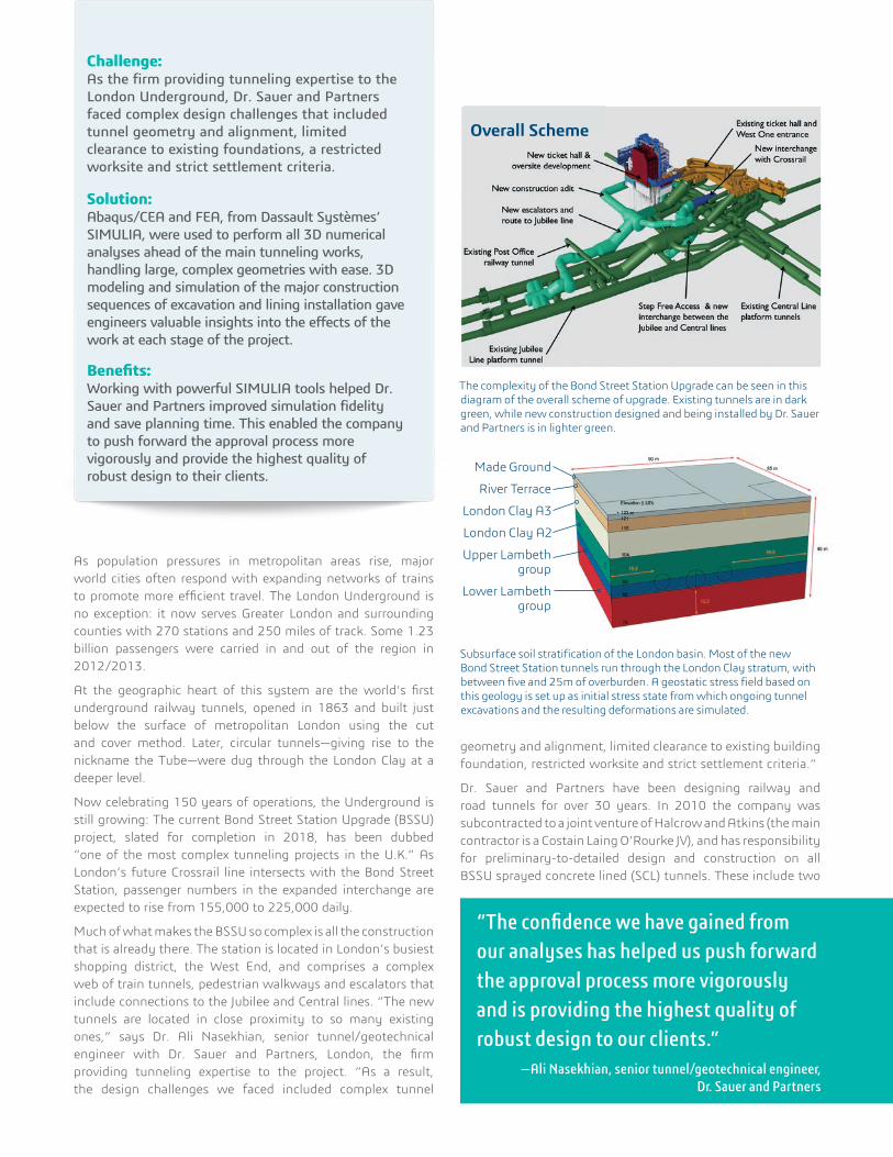
The complexity of the Bond Street Station Upgrade can be seen in this diagram of the overall scheme of upgrade. Existing tunnels are in dark green, while new construction designed and being installed by Dr. Sauer and Partners is in lighter green.
Overall Scheme
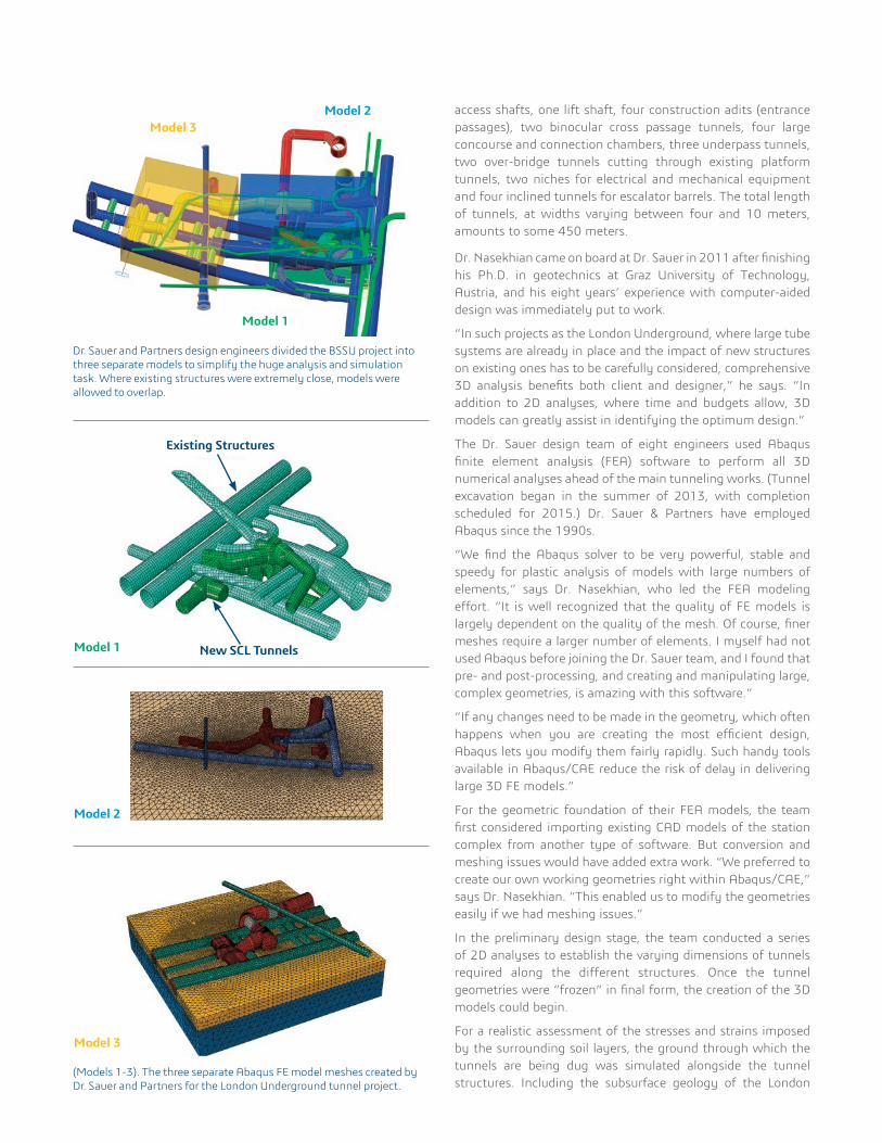
Subsurface soil stratification of the London basin. Most of the new Bond Street Station tunnels run through the London Clay stratum, with between five and 25m of overburden. A geostatic stress field based on this geology is set up as initial stress state from which ongoing tunnel excavations and the resulting deformations are simulated.
Made Ground
River Terrace
London Clay A3
London Clay A2
Upper Lambeth group
Lower Lambeth group
access shafts, one lift shaft, four construction adits (entrance passages), two binocular cross passage tunnels, four large concourse and connection chambers, three underpass tunnels, two over-bridge tunnels cutting through existing platform tunnels, two niches for electrical and mechanical equipment and four inclined tunnels for escalator barrels. The total length of tunnels, at widths varying between four and 10 meters, amounts to some 450 meters.
Dr. Nasekhian came on board at Dr. Sauer in 2011 after finishing his Ph.D. in geotechnics at Graz University of Technology, Austria, and his eight years’ experience with computer-aided design was immediately put to work.
“In such projects as the London Underground, where large tube systems are already in place and the impact of new structures on existing ones has to be carefully considered, comprehensive 3D analysis benefits both client and designer,” he says. “In addition to 2D analyses, where time and budgets allow, 3D models can greatly assist in identifying the optimum design.”
The Dr. Sauer design team of eight engineers used Abaqus finite element analysis (FEA) software to perform all 3D numerical analyses ahead of the main tunneling works. (Tunnel excavation began in the summer of 2013, with completion scheduled for 2015.) Dr. Sauer & Partners have employed Abaqus since the 1990s.
“We find the Abaqus solver to be very powerful, stable and speedy for plastic analysis of models with large numbers of elements,” says Dr. Nasekhian, who led the FEA modeling effort. “It is well recognized that the quality of FE models is largely dependent on the quality of the mesh. Of course, finer meshes require a larger number of elements. I myself had not used Abaqus before joining the Dr. Sauer team, and I found that pre- and post-processing, and creating and manipulating large, complex geometries, is amazing with this software.”
“If any changes need to be made in the geometry, which often happens when you are creating the most efficient design, Abaqus lets you modify them fairly rapidly. Such handy tools available in Abaqus/CAE reduce the risk of delay in delivering large 3D FE models.”
For the geometric foundation of their FEA models, the team first considered importing existing CAD models of the station complex from another type of software. But conversion and meshing issues would have added extra work. “We preferred to create our own working geometries right within Abaqus/CAE,” says Dr. Nasekhian. “This enabled us to modify the geometries easily if we had meshing issues.”
In the preliminary design stage, the team conducted a series of 2D analyses to establish the varying dimensions of tunnels required along the different structures. Once the tunnel geometries were “frozen” in final form, the creation of the 3D models could begin.
For a realistic assessment of the stresses and strains imposed by the surrounding soil layers, the ground through which the tunnels are being dug was simulated alongside the tunnel structures. Including the subsurface geology of the London
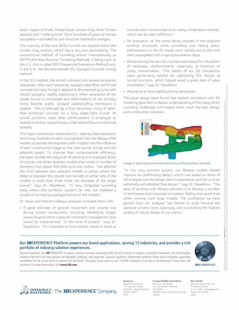
Dr. Sauer and Partners design engineers divided the BSSU project into three separate models to simplify the huge analysis and simulation task. Where existing structures were extremely close, models were allowed to overlap.
Model 2Model 3
Model 1
(Models 1-3). The three separate Abaqus FE model meshes created by Dr. Sauer and Partners for the London Underground tunnel project.
Model 3
Model 2
Model 1 New SCL Tunnels
Existing Structures
basin—layers of Chalk, Thanet Sand, London Clay, River Terrace deposits and “made ground” from hundreds of years of human occupation—provided for soil-structure interaction analysis.
The majority of the new BSSU tunnels are located within the London Clay stratum, which has a very low permeability. The conventional method of tunneling known internationally as NATM (the New Austrian Tunneling Method), is being used. In the U.S. this is called SEM (Sequential Excavation Method) and, in the U.K., the aforementioned SCL (Sprayed Concrete Lining) method.
In the SCL method, the tunnel is divided into several excavation sequences; after each sequence, sprayed steel-fiber-reinforced concrete (primary lining) is applied to the exposed ground with robotic sprayers, rapidly stabilizing it. When excavation of the whole tunnel is completed and deformations of the primary lining become stable, sprayed waterproofing membrane is applied. This is followed by a final secondary lining of steel-fiber-reinforced concrete for a fully water-tight tunnel. At tunnel junctions, steel rebar reinforcement is employed as needed to further support areas under severe flexure and tensile stresses.
The major construction sequences (i.e., step-by-step excavation and lining installation) were incorporated into the Abaqus FEA models to provide the engineers with insights into the influence of each construction stage on the new tunnel linings and the adjacent assets. To improve their computational efficiency, the team divided the labyrinth of existing and proposed BSSU structures into three separate models that varied in number of elements from about 450,000 up to one million. “We selected the limit between two adjacent models in places where the distance between the closest two tunnels on either side of the models is more than three times the diameter of the larger tunnel,” says Dr. Nasekhian. “In very congested tunneling areas where this condition couldn’t be met, we modeled a couple of tunnels by overlapping two of the models.”
Dr. Sauer and Partner’s Abaqus analyses provided them with:
• A good estimate of ground movement and volume loss during tunnel construction, including identifying trigger values beyond which a ground-movement management plan would be implemented. “In this kind of project,” says Dr. Nasekhian, “it’s important to have realistic values in hand so
tunnels aren’t constructed in an overly conservative manner, which can be cost-ineffective.”
• An evaluation of the stress being induced in the adjacent existing structures while tunneling was taking place. Deformations in the FE model were initially set at zero and then propagated with ongoing excavation steps.
• Dimensioning the new SCL tunnels and a basis for calculation of necessary reinforcements, especially at locations of stress concentration. “The results of our 3D simulations were particularly helpful for optimizing SCL design at tunnel junctions, which helped avoid a great deal of rebar installation,” says Dr. Nasekhian.
• Assurance of face stability during excavation.
The Sauer design team found that realistic simulation with 3D modeling gave them a deeper understanding of the many BSSU tunneling challenges and helped them reach the best design and construction solutions.
“In this very complex project, our Abaqus models helped improve our preliminary design, which was based on series of 2D analyses and the design team’s experience, and led us to an extremely well-detailed final design,” says Dr. Nasekhian. “The ease of working with Abaqus allowed us to develop a number of techniques that improved simulation fidelity and saved time when running such large models. The confidence we have gained from our analyses has helped us push forward the approval process more vigorously and is providing the highest quality of robust design to our clients.”
Image 5. Vertical ground movement around the southern tunnels.
Our 3DEXPERIENCE Platform powers our brand applications, serving 12 industries, and provides a rich portfolio of industry solution experiences. Dassault Systèmes, the 3DEXPERIENCE Company, provides business and people with virtual universes to imagine sustainable innovations. Its world-leading solutions transform the way products are designed, produced, and supported. Dassault Systèmes’ collaborative solutions foster social innovation, expanding possibilities for the virtual world to improve the real world. The group brings value to over 170,000 customers of all sizes in all industries in more than 140 countries. For more information, visit www.3ds.com.
Europe/Middle East/AfricaDassault Systèmes10, rue Marcel DassaultCS 4050178946 Vélizy-Villacoublay CedexFrance
AmericasDassault Systèmes175 Wyman StreetWaltham, Massachusetts02451-1223USA
Asia-PacificDassault Systèmes K.K.ThinkPark Tower2-1-1 Osaki, Shinagawa-ku,Tokyo 141-6020Japan
©20
14 D
assa
ult S
ystè
mes
. All
righ
ts re
serv
ed. 3
DEX
PER
IEN
CE, t
he C
ompa
ss ic
on a
nd th
e 3D
S lo
go, C
ATI
A, S
OLI
DW
OR
KS, E
NO
VIA
, DEL
MIA
, SIM
ULI
A, G
EOVI
A, E
XALE
AD
, 3D
VIA
, BIO
VIA
, NET
VIB
ES, a
nd 3
DXC
ITE
are
com
mer
cial
trad
emar
ks
or re
gist
ered
trad
emar
ks o
f Das
saul
t Sys
tèm
es o
r its
sub
sidi
arie
s in
the
U.S
. and
/or o
ther
cou
ntri
es. A
ll ot
her t
rade
mar
ks a
re o
wne
d by
thei
r res
pect
ive
owne
rs. U
se o
f any
Das
saul
t Sys
tèm
es o
r its
sub
sidi
arie
s tr
adem
arks
is s
ubje
ct to
thei
r exp
ress
wri
tten
app
rova
l.