Embed Size (px)
Citation preview
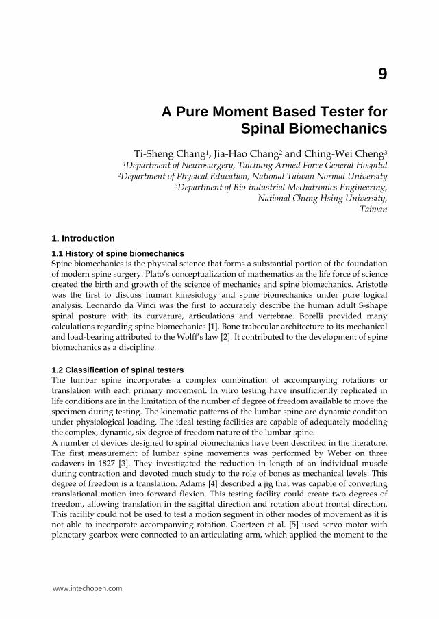
9
A Pure Moment Based Tester for Spinal Biomechanics
Ti-Sheng Chang1, Jia-Hao Chang2 and Ching-Wei Cheng3 1Department of Neurosurgery, Taichung Armed Force General Hospital
2Department of Physical Education, National Taiwan Normal University 3Department of Bio-industrial Mechatronics Engineering,
National Chung Hsing University, Taiwan
1. Introduction
1.1 History of spine biomechanics Spine biomechanics is the physical science that forms a substantial portion of the foundation
of modern spine surgery. Plato’s conceptualization of mathematics as the life force of science
created the birth and growth of the science of mechanics and spine biomechanics. Aristotle
was the first to discuss human kinesiology and spine biomechanics under pure logical
analysis. Leonardo da Vinci was the first to accurately describe the human adult S-shape
spinal posture with its curvature, articulations and vertebrae. Borelli provided many
calculations regarding spine biomechanics [1]. Bone trabecular architecture to its mechanical
and load-bearing attributed to the Wolff’s law [2]. It contributed to the development of spine
biomechanics as a discipline.
1.2 Classification of spinal testers The lumbar spine incorporates a complex combination of accompanying rotations or
translation with each primary movement. In vitro testing have insufficiently replicated in
life conditions are in the limitation of the number of degree of freedom available to move the
specimen during testing. The kinematic patterns of the lumbar spine are dynamic condition
under physiological loading. The ideal testing facilities are capable of adequately modeling
the complex, dynamic, six degree of freedom nature of the lumbar spine.
A number of devices designed to spinal biomechanics have been described in the literature. The first measurement of lumbar spine movements was performed by Weber on three cadavers in 1827 [3]. They investigated the reduction in length of an individual muscle during contraction and devoted much study to the role of bones as mechanical levels. This degree of freedom is a translation. Adams [4] described a jig that was capable of converting translational motion into forward flexion. This testing facility could create two degrees of freedom, allowing translation in the sagittal direction and rotation about frontal direction. This facility could not be used to test a motion segment in other modes of movement as it is not able to incorporate accompanying rotation. Goertzen et al. [5] used servo motor with planetary gearbox were connected to an articulating arm, which applied the moment to the
www.intechopen.com
Biomechanics in Applications 206
cranial end of the specimen. Lysack et al. [6] involved the use of a linear actuator with cable system and roller bearings to produce moments. Their apparatus allowed continuous cycling loading. They could supply continuous loading, however, the direction of movement was limited. In the meantime, they needed to change the position of the specimen under different loading (such as flexion-extension-flexion). More complicated apparatus have been constructed to allow for loading to be controlled in more than one plane of rotation. Goel et al. [7] used deadweights and cables acting about pulleys to produce force couples. Yamamoto et al. [8] defined the implementation of pneumatic actuators. They used paired vacuum-operated low friction glass cylinders to produce pure moment condition. Wilke et al. [9] suspended the stepper motors and a pneumatic system over the specimen and used a gimbal joint and XYZ slide to allow the motors to follow the motion and orientation of the upper fixtures. These testing facilities are force controlled rather than displacement controlled and cannot reproduce the kinematic patterns of the lumbar spine. This force application is also under quasi-static conditions, rather dynamic conditions. Quasi-static conditions are a poor representation of dynamic loading [10]. Hence, these methods are incapable of reproducing physiological loading of the specimen. Stokes et al. [11] used a series of six linear actuators to enable the six degrees of freedom to be independently controlled. Six linear encoders were utilized to measure and control the displacement of the testing machine. This facility was displacement-control mode, they usually needs complex mathematical calculation before data analysis. A robot [12] is capable of motion in six degree of freedom (DOF) and is able to dynamically test a specimen throughout its entire range of motion. When coupled with an appropriate force transducer, a robot material testing facility is able to provide kinetic information for the simulated condition in life spinal motion. This is an ideal facility for spine biomechanical study. However, the price of this facility was relative high. Not every institute has the resource to use it. Under this thinking process, a pure moment based spinal tester with the backbone of robot and relative cheap price to perform spinal biomechanical study should be developed.
2. Biomechanical parameters
2.1 Clinical associated biomechanical parameters Several parameters may be obtained through biomechanical tests of flexibility to quantify mechanical properties [13]. Such parameters include range of motion (ROM), neutral zone (NZ) and elastic zone (EZ). NZ is the displacement at the zero-load point measure from the neutral position [13-14]. EZ is the displacement from the zero-load point to the maximum load point. ROM is the displacement from the neutral position to the maximum load point, that is, the sum of NZ and EZ. In biomechanical study, the ROM represents the stability of the specimen before and after additional procedures (including destructive and stabilizing procedures). The NZ indicates the laxity around the neutral position of a motion segment and residual deformation after removing a defined pure moment load from a motion segment. Mimura et al. [15] revealed that, in flexion-extension and lateral bending, ROM decreases and NZ increases during disc degeneration. In the early stage of disc degeneration, ROM increases while in the late stage of disc degeneration, ROM decreases. If only ROM is used as the measurement parameter, misinterpretations are likely. Previous in vitro studies indicated that NZ typically increases after experimentally induced injuries [16-17], and that it decreases with the addition of muscle forces and spinal instrumentation [18].
www.intechopen.com
A Pure Moment Based Tester for Spinal Biomechanics 207
2.2 Flexibility and stiffness Flexibility is ratio of strain to stress that is the ability of the structure to deform under the application of a load. Stiffness is the opposite. It is ratio of stress to strain in a loaded material that is the stress divided by the relative amount of change in the structure’s shape. Panjabi [19] outlined the biomechanical testing of a spinal segment as including both stiffness and flexibility methods. In stiffness method (displacement-control), the free end of specimen was displaced, and the resulting forces and moments in the specimen were measured. The application of a given displacement at the superior-most vertebral body imposed complex loads of varying magnitudes along the spinal segment because of coupling behavior of the spine. This method provided kinetic information for the simulated condition in life spinal motion. Although the magnitude of the complex load could be quantified with a six-axis load cell, it was not practical to measure those all along the spinal segment. It usually needs complex mathematical calculation. In the flexibility method (load-control), a load was applied to the free vertebra of the specimen and the resulting displacements of the vertebra were measured. This method allowed complete freedom of movements of all the vertebra of the spine, thereby allowing natural behavior of the spinal column to take place. The in vitro biomechanical study could be standardized under this way [20].
2.3 Pure moment The most common method used currently is flexibility protocol. Panjabi [19] emphasized that non-constraining pure moment load is warranted. Pure moment means that pure bending moments or the pure shear moments depend on the direction of action. There is no force during measurement. Pure bending moments include flexion, extension, left and right lateral bending direction. Pure shear moments include right and left axial rotation direction. The spinal anatomy is not a uniform structure. The loads at a cross section are proportional to the bending moment (force × level arm) at the cross section. An anterior directed horizontal force or eccentric compression load cannot produce uniform bending moment through the whole length of the specimen. The purpose of pure moment loading is to supply the same magnitude at each cross section throughout the whole length of the construct [19]. Non-constraining construct means that one side is fixed to the apparatus and the other end is free to move, allowing the natural spinal movements. The use of non-constraining pure moments ensures that the load experienced by a specimen remains constant along its length independent of its geometry, motion or, stiffness. This means that, throughout the loading cycle, the loading conditions at any two cross-sections in the spinal column are identical. The major advantage of pure moment loading is that it allows for the comparison of the biomechanical properties of different spinal constructs.
3. Self-design pure moment based spinal tester
3.1 Equipment and hardware This pure moment based spinal tester contained power supply unit, measurement unit, associated hardware and control unit. Power supply unit included 4 servo motors and planetary reduction gearbox. Measurement unit included load cell and multi-axis force/torque sensor controller. The control unit included computer and 2 RS-232 PCI Cards. These set up allows for communications with both tester and load cell through single purpose written program on one PC. The picture of this tester was shown in Figure 1.
www.intechopen.com
Biomechanics in Applications 208
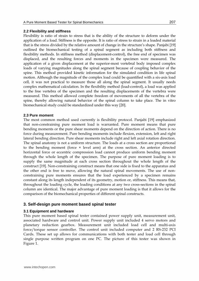
Fig. 1. The testing machine and mounting system with a specimen during performance of a flexibility test. Various component of this tester is illustrated. Reprinted from Journal of Medical and Biological Engineering, vol 29, No 1, Chang, T.S. et. al, a new multi-direction tester for evaluation of the spinal biomechanics, p 7-13, 2009, with kind permission from Taiwanese Society of Biomedical Engineering [21].
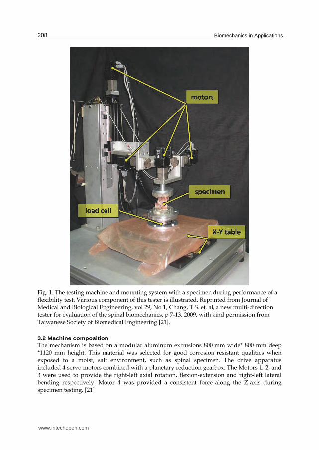
3.2 Machine composition The mechanism is based on a modular aluminum extrusions 800 mm wide* 800 mm deep *1120 mm height. This material was selected for good corrosion resistant qualities when exposed to a moist, salt environment, such as spinal specimen. The drive apparatus included 4 servo motors combined with a planetary reduction gearbox. The Motors 1, 2, and 3 were used to provide the right-left axial rotation, flexion-extension and right-left lateral bending respectively. Motor 4 was provided a consistent force along the Z-axis during specimen testing. [21]
www.intechopen.com
A Pure Moment Based Tester for Spinal Biomechanics 209
3.3 Coordinated system The coordinate system was the junction of the posterior one-third and anterior two-third of the intervertebral disc. The +z-axis was described upward from the origin, the +y-axis pointed to the left, and the +x-axis pointed forward. The +Fx/–Fx, +Fy/ –Fy and +Fz/–Fz represented anterior/posterior, left/right and decompression/compression axial force, and +Mx/–Mx, +My/–My and +Mz/–Mz represented right/left bending, flexion/extension and right/left rotation moment, respectively.
Fig. 2. The Multi-degree spine tester (a) full view (b) close-up of the apparatus set for each motion . Reprinted from Journal of Medical and Biological Engineering, vol 29, No 1, Chang, T.S. et. al, a new multi-direction tester for evaluation of the spinal biomechanics, p 7-13, 2009, with kind permission from Taiwanese Society of Biomedical Engineering [21].
www.intechopen.com
Biomechanics in Applications 210
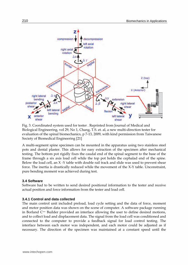
Fig. 3. Coordinated system used for tester . Reprinted from Journal of Medical and Biological Engineering, vol 29, No 1, Chang, T.S. et. al, a new multi-direction tester for evaluation of the spinal biomechanics, p 7-13, 2009, with kind permission from Taiwanese Society of Biomedical Engineering [21]
A multi-segment spine specimen can be mounted in the apparatus using two stainless steel pots and dental plaster. This allows for easy extraction of the specimen after mechanical testing. The bottom pot rigidly fixes the caudal end of the spinal segment to the base of the frame through a six axis load cell while the top pot holds the cephalad end of the spine. Below the load cell, an X -Y table with double rail track and slide was used to prevent shear force. The inertia is drastically reduced while the movement of the X-Y table. Unconstraint, pure bending moment was achieved during test.
3.4 Software Software had to be written to send desired positional information to the tester and receive actual position and force information from the tester and load cell.
3.4.1 Control and data collected The main control unit included preload, load cycle setting and the data of force, moment and motor position data was shown on the scene of computer. A software package running in Borland C++ Builder provided an interface allowing the user to define desired motions, and to collect load and displacement data. The signal from the load cell was conditioned and connected to the computer to provide a feedback signal for load control testing. The interface between each motor was independent, and each motor could be adjusted as if necessary. The direction of the specimen was maintained at a constant speed until the
www.intechopen.com
A Pure Moment Based Tester for Spinal Biomechanics 211
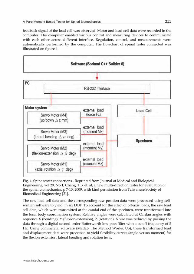
feedback signal of the load cell was observed. Motor and load cell data were recorded in the computer. The computer enabled various control and measuring devices to communicate with each other across different interface. Regulation, control, and measurements were automatically performed by the computer. The flowchart of spinal tester connected was illustrated on figure 4.
Fig. 4. Spine tester connections . Reprinted from Journal of Medical and Biological Engineering, vol 29, No 1, Chang, T.S. et. al, a new multi-direction tester for evaluation of the spinal biomechanics, p 7-13, 2009, with kind permission from Taiwanese Society of Biomedical Engineering [21].
The raw load cell data and the corresponding raw position data were processed using self-
written software to yield, in six DOF. To account for the effect of off-axis loads, the raw load
cell data, which were transmitted at the caudal end of the specimen, were transformed into
the local body coordination system. Relative angles were calculated at Cardan angles with
sequence X (bending), Y (flexion-extension), Z (rotation). Noise was reduced by passing the
data through a digital second-order Butterworth low-pass filter with a cutoff frequency of 5
Hz. Using commercial software (Matlab, The Method Works, US), these transformed load
and displacement data were processed to yield flexibility curves (angle versus moment) for
the flexion-extension, lateral bending and rotation tests.
www.intechopen.com
Biomechanics in Applications 212
3.5 Verification of spine tester To verify this spine tester, a circular cylinder was used. The cylinder was formed from polyurethane (PU diameter 25 mm, length 90 mm), which is a homogenous polymer. Table 1 shows the physical properties of PU. The PU could be mounted on the apparatus using two aluminum pots and polyester resin plaster. Two stainless steel screws inserted above and below the pots rigidly secured the PU to the tester. The test protocol was to apply pure bending moments to the PU to a maximum of 2 Nm in right-left lateral bending (M3), flexion-extension (M2) and right-left axial rotation (M1) in sequence. Rotation velocity was 1°/sec. A real-time graphical display of servo motor angle and applied moment was
available during the test. The direction was reversed when the moment reached ±2 Nm.
After cycling the PU five times, mean values and standard deviations were calculated. No compressive preloads were applied. Torque was measured ten times at intervals of 0.4 Nm. Physical property Value Hardness (kg/mm2) 8 Specific gravity (g/cm3) 0.904 Heat distortion temperature (kg/cm2) 90 Hydraulic strength (kg-cm/cm) 1.6 Elastic modulus of bending (kg/cm2) 18500 Elastic modulus of shear (kg/cm2) 46500 Poisson’s ratio 0.23~0.38
Table 1. Physical property of polyurethane (PU).
The calculated value was from equation (A) and (B) [22]. Which
p
dT GI
dx
(A)
Where Τ = torque.
dψ/dx = twist rate.
Ip = polar moment of inertia G = shear modulus of elasticity
M - EIL
(B)
Where M = bending moment E = elastic bending modulus I = inertia L = length θ = angle of bending
The error rates for flexion-extension, lateral bending and axial rotation were about 2.16 %, 2.66% and 1.36%, respectively. The PU examination results revealed larger errors in flexion-extension and in lateral bending than in rotation (2.16%, 2.66% and 1.36%, respectively). This may have been due to the X-Y table. The error even reach around 5% at the beginning
www.intechopen.com
A Pure Moment Based Tester for Spinal Biomechanics 213
of flexion-extension (5.15% and 4.22% at -0.4 and +0.4 Nm). More loading was needed to start the X-Y table. Fortunately, the error rate decreased progressively as load approached maximum. In most biomechanical studies, data are recorded from the end loading. This condition did not substantially affect the final results, and it could be eliminated entirely if a servo motor is used to drive the X-Y table [21].
4. Application of this tester
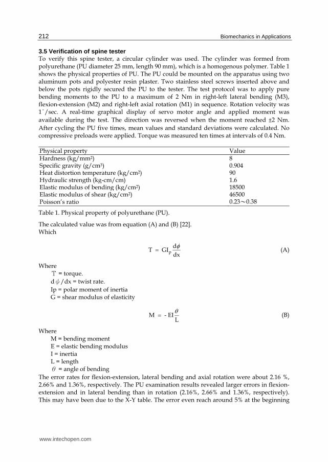
4.1 Spinal unit function evaluating the changes in ROM and NZ after discectomy and implantation by sheep spine One motion segment of L4/5 from one sheep lumbar spine was used for testing of this tester. The specimen was tested intact to serve as its own control. The various surgical procedures (figure 5) including laminectomy, discectomy and transpedicular screw fixation were performed. Laminectomy was performed with Kerrison rongeur, after resection of the spinous process and the interspinous and supraspinous ligaments. The lamina was removed out to the most medial portion of the articular facet. Care was taken to preserve the pars interarticularis. The cranial limit of the resection was the corresponding pedicle. The ligamentum flavum was removed, also. The posterior longitudinal ligament and the annulus were incised using No. 15 blade. Discectomy was practiced at the L4/5 intervertebral space. It was accomplished through an incision of square shape in the annulus fibrosis just anterior to the plane of the pedicle, and approximately 70% of the disc material was removed with disc forcep and curret. Transpedicular screw fixation was practiced within the L4 and L5 pedicle, and an ISOLA system was connected.
Fig. 5. Various surgical procedures was illustrated.
Biomechanical testing of sheep lumbar spine was performed using a non-destructive, flexibility method of testing under non-constraining pure moment loads. Pure bending moments were applied to the specimen to a maximum of 2 Nm in right-left lateral bending (M3), flexion-extension (M2) and right-left axial rotation (M1) in sequence after different surgical procedure. The velocity of rotation is 1 degree per second. The load cell provided a feedback signal to the computer through RS-232 interface with 40 Hz sampling rate. A real time graphical display of servo motor angle and applied moment was available during the test. The direction was reversed when the moment reached ±2 Nm. The specimen were
cycled for a total of five cycles- the first four cycles were considered preconditioning and the fifth cycle was used for analysis. No compressive preloads were applied, and approximately five minutes were allowed between tests for viscoelastic recovery.
www.intechopen.com
Biomechanics in Applications 214
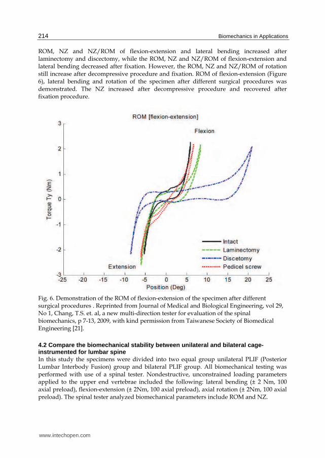
ROM, NZ and NZ/ROM of flexion-extension and lateral bending increased after laminectomy and discectomy, while the ROM, NZ and NZ/ROM of flexion-extension and lateral bending decreased after fixation. However, the ROM, NZ and NZ/ROM of rotation still increase after decompressive procedure and fixation. ROM of flexion-extension (Figure 6), lateral bending and rotation of the specimen after different surgical procedures was demonstrated. The NZ increased after decompressive procedure and recovered after fixation procedure.
Fig. 6. Demonstration of the ROM of flexion-extension of the specimen after different surgical procedures . Reprinted from Journal of Medical and Biological Engineering, vol 29, No 1, Chang, T.S. et. al, a new multi-direction tester for evaluation of the spinal biomechanics, p 7-13, 2009, with kind permission from Taiwanese Society of Biomedical Engineering [21].
4.2 Compare the biomechanical stability between unilateral and bilateral cage-instrumented for lumbar spine In this study the specimens were divided into two equal group unilateral PLIF (Posterior Lumbar Interbody Fusion) group and bilateral PLIF group. All biomechanical testing was performed with use of a spinal tester. Nondestructive, unconstrained loading parameters applied to the upper end vertebrae included the following: lateral bending (± 2 Nm, 100 axial preload), flexion-extension (± 2Nm, 100 axial preload), axial rotation (± 2Nm, 100 axial preload). The spinal tester analyzed biomechanical parameters include ROM and NZ.
www.intechopen.com
A Pure Moment Based Tester for Spinal Biomechanics 215
Twelve motion segments of L4/5 from twelve sheep lumbar spines were studied for this in-vitro investigation. At the time of salvage, the animals were 12-18 months old and weighted
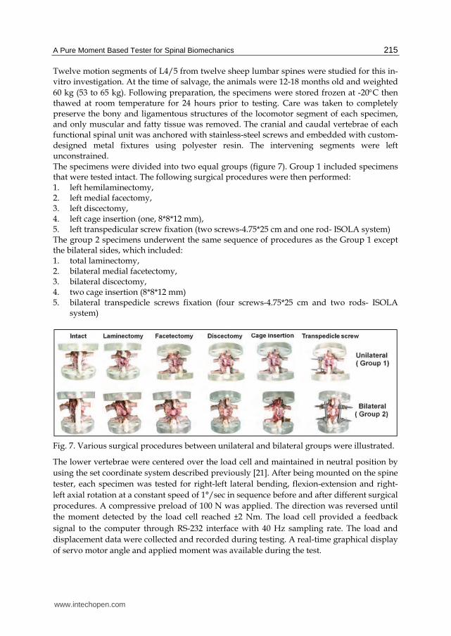
60 kg (53 to 65 kg). Following preparation, the specimens were stored frozen at -20C then thawed at room temperature for 24 hours prior to testing. Care was taken to completely preserve the bony and ligamentous structures of the locomotor segment of each specimen, and only muscular and fatty tissue was removed. The cranial and caudal vertebrae of each functional spinal unit was anchored with stainless-steel screws and embedded with custom-designed metal fixtures using polyester resin. The intervening segments were left unconstrained. The specimens were divided into two equal groups (figure 7). Group 1 included specimens that were tested intact. The following surgical procedures were then performed: 1. left hemilaminectomy, 2. left medial facectomy, 3. left discectomy, 4. left cage insertion (one, 8*8*12 mm), 5. left transpedicular screw fixation (two screws-4.75*25 cm and one rod- ISOLA system) The group 2 specimens underwent the same sequence of procedures as the Group 1 except the bilateral sides, which included: 1. total laminectomy, 2. bilateral medial facetectomy, 3. bilateral discectomy, 4. two cage insertion (8*8*12 mm) 5. bilateral transpedicle screws fixation (four screws-4.75*25 cm and two rods- ISOLA
system)
Fig. 7. Various surgical procedures between unilateral and bilateral groups were illustrated.
The lower vertebrae were centered over the load cell and maintained in neutral position by
using the set coordinate system described previously [21]. After being mounted on the spine
tester, each specimen was tested for right-left lateral bending, flexion-extension and right-
left axial rotation at a constant speed of 1°/sec in sequence before and after different surgical
procedures. A compressive preload of 100 N was applied. The direction was reversed until
the moment detected by the load cell reached ±2 Nm. The load cell provided a feedback
signal to the computer through RS-232 interface with 40 Hz sampling rate. The load and
displacement data were collected and recorded during testing. A real-time graphical display
of servo motor angle and applied moment was available during the test.
www.intechopen.com
Biomechanics in Applications 216
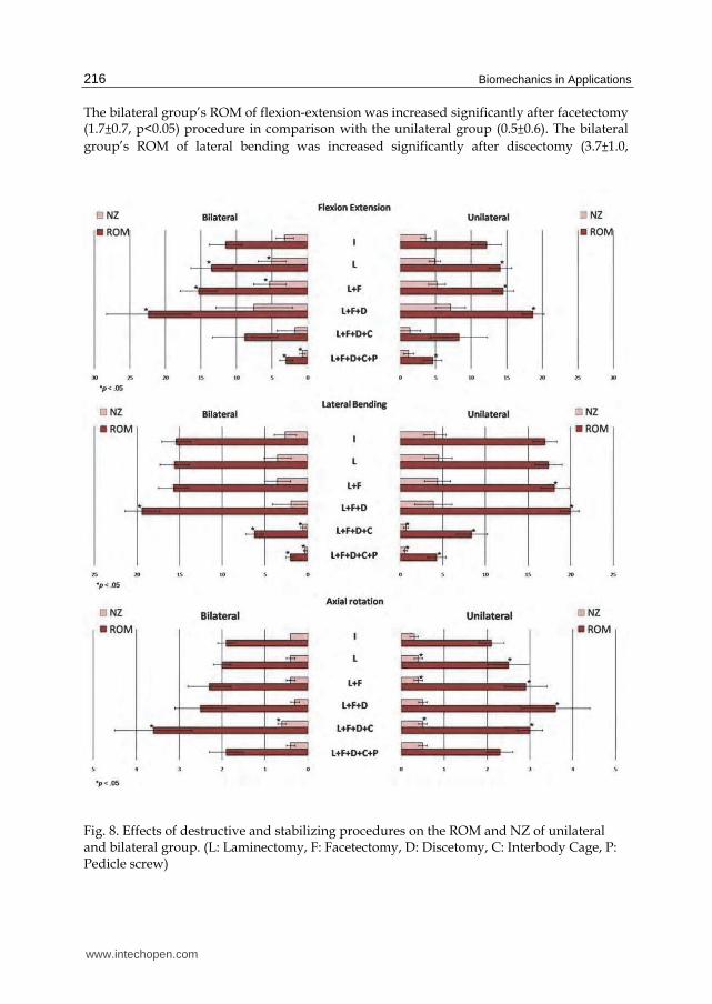
The bilateral group’s ROM of flexion-extension was increased significantly after facetectomy (1.7±0.7, p<0.05) procedure in comparison with the unilateral group (0.5±0.6). The bilateral
group’s ROM of lateral bending was increased significantly after discectomy (3.7±1.0,
Fig. 8. Effects of destructive and stabilizing procedures on the ROM and NZ of unilateral and bilateral group. (L: Laminectomy, F: Facetectomy, D: Discetomy, C: Interbody Cage, P: Pedicle screw)
www.intechopen.com
A Pure Moment Based Tester for Spinal Biomechanics 217
p<0.05) procedure in comparison with the unilateral group (1.8±1.6). The bilateral group’s
ROM of axial rotation was increased significantly after cage insertion (1.1±0.9, p<0.05)
procedure in comparison with the unilateral group (-0.6±0.6). The bilateral group’s ROM of
axial rotation was decreased significantly after discectomy (0.2±0.3 vs 0.7±0.4, p<0.05) and
transpedicle screw insertion (-1.7±0.8 vs -0.7±0.4, p<0.05) procedure in comparison with the
unilateral group. The bilateral group’s NZ of axial rotation was increased significantly after cage insertion (0.3±0.1, p<0.05) procedure in comparison with the unilateral group (0.0±
0.2).The bilateral group’s NZ of axial rotation was decreased significantly after laminectomy (0.0±0.1 vs 0.1±0.0, p<0.05) and discectomy (-0.1±0.1 vs 0.1±0.1, p<0.05) procedure in
comparison with the unilateral group (figure 8). Based on the results of this study, both ROM and NZ, unilateral cage-instrumented PLIF and bilateral cage-instrumented PLIF, transpedicle screw insertion procedure did not revealed a significant difference between flexion-extension, lateral bending and axial rotation direction except the ROM in the axial rotation.
5. Conclusion
This pure moment based spinal tester is capable of motion in six degree of freedom and is able to dynamically test a specimen throughout its entire range of motion. It can provide kinetic information for the simulated condition in life spinal motion. This is an ideal facility for spine biomechanical study. It has minimal weight moving over the specimen, thus minimizing friction and inertial effects. This allows the plotting of complete moment-displacement curves from which the characteristic flexibility parameters of interest can be calculated for each spine specimen in real time. The ability of calculated ROM and NZ is of particular importance given the clinical instability of a spinal segment. This multi-directional spinal tester is an effective and practical machine in the biomechanical study of spine.
6. Reference
[1] S. Naderi, N. Andalkar, and E, Benzel, “History of spine biomechanics: Part I- the pre-Greco-Roman, Greco-Roman, and Medieval roots of spine biomechanics”, Neurosurgery 60: 382-391, 2007.
[2] S. Naderi, N. Andalkar, and E. Benzel, “History of spine biomechanics: Part II- from the renaissance to the 20th century”, Neurosurgery 60: 392-404, 2007.
[3] E.H. Weber, “Anatomical and physiological tests on some systems of human spine mechanism”, Arch. anat .physiol 1: 240-271, 1827.
[4] M.A. Adams, “Spine update mechanical testing of the spine- an appraisal of methodology, results, and conclusions” Spine 20: 2151-2156, 1995.
[5] D.J. Goertzen, C. Lane, and T. R. Oxland, “Neutral zone and range of motion in the spine are greater with stepwise loading than with a continuous loading protocol. An in vitro porcine investigation” Journal of Biomechanics 37: 127-261, 2004.
[6] J.T. Lysack, J.P. Dickey, G.A. Dumas and D. Yen, “A continuous pure moment loading apparatus for biomechanical testing of multi-segment spine specimens”, J. Biomech 33: 765-770, 2000.
www.intechopen.com
Biomechanics in Applications 218
[7] V.K. Goel, S. Goyal, and C. Clark, ”Kinematics of the whole lumbar spine: effect of discectomy”, Spine 10: 543-554, 1985.
[8] Yamatoma, M.M. Panjabi, T. Criso and T.R. Oxland, “Three-dimensional movements of the whole lumbar spine and lumbosacral joints”, Spine 14:1256-1260, 1989.
[9] H.J. Wilke, L . Claes, H. Schmitt and S. Wolf, “A universal spine tester for in vitro experiments with muscle force stimulation”, Eur. Spine. J 3:91-97, 1994.
[10] V, Yingling, J. Callaghan, and S. McGill, ”Dynamic loading affects the mechanical properties and failure site of porcine spines” Clinical Biomechanics 12: 301-305, 1997.
[11] I.A. Strokes, M. Gardner-Morse, D. Churchill, and J.P. Laible, “Measurement of a spinal motion segment stiffness matrix”, J. Biomech 35: 517-521, 2002.
[12] R.E. Thompson, T.M. Barker and M.J. Pearcy, “Defining the neutral zone of sheep intervertebral joints during dynamic motions: an in vitro study” clinical Biomechanics 18: 89-98, 2003.
[13] M.M. Panjabi, ”The stabilizing system of the spine. Part II. Neutral zone and instability hypothesis”, J. Spinal Disord 5: 390-397, 1992.
[14] M.M. Panjabi, ”The stabilizing system of the spine. Part I. Function, dysfunction, adaptation, and enhancement”,J. Spinal Dis,5: 383-389, 1992.
[15] M. Mimura, M.M. Panjabi, T.R. Oxland, T.J. Criso, I.I. Yamamoto, and A .Vasavada, ”Disc degeneration affects the multidirectional flexibility of the lumbar spine”, Spine 19: 1371-1380, 1994.
[16] M.M. Panjabi, M. Kifune, W. Liu, M. Arand, A. Vasavada, and T.R. Oxland, “Graded thoracolumbar spine injuries: development of multidirectional instability”, Eur Spine J 7: 332-339, 1998.
[17] T.R. Oxland, and M.M. Panjabi, ”The onset and progression of spinal injury: a determination of neutral zone sensitivity”, J. Biomech 25: 1165-1172, 1992.
[18] H.J. Wilke, S. Wolf, L.E. Claes, M. Arand, and A. Wiesue, ”Stability increase of the lumbar spine with different muscle groups. A biomechanical in vitro study”, Spine 20: 192-198, 1995.
[19] M.M. Panjabi, ”Biomechanical evaluation of spine fixation devices: I A conceptual framework”, Spine 13:1129-1134, 1988.
[20] V.K. Goel, D.G Wilder, M.H. Pope and W.E. Edwards, “Biomechanical testing of the spine: Load-controlled versus displacement-controlled analysis”, Spine 20:2354-2357, 1995.
[21] T.S. Chang, C.W. Cheng, C.S. Wang, H.Y. Chen, and J.H. Chang, ”A New Multi-direction Tester for Evaluation of the Spinal Biomechanics”, Journal of Medical and Biological Engineering 29(1): 7-13, 2009.
[22] R.R. Craig, “Mechanics of Materials”, First ed, Toronto: John Wiley & Sons Inc, pp 175-179, 1996.
[23] T.S. Chang, J.H. Chang, C.S. Wang, H.Y. Chen, and C.W. Cheng, ”Evaluation of unilateral cage-instrumented fixation for lumbar spine”, Journal of Orthopaedic Surgery and Research 5:86
www.intechopen.com
Biomechanics in ApplicationsEdited by Dr Vaclav Klika
ISBN 978-953-307-969-1Hard cover, 408 pagesPublisher InTechPublished online 09, September, 2011Published in print edition September, 2011
InTech EuropeUniversity Campus STeP Ri Slavka Krautzeka 83/A 51000 Rijeka, Croatia Phone: +385 (51) 770 447 Fax: +385 (51) 686 166www.intechopen.com
InTech ChinaUnit 405, Office Block, Hotel Equatorial Shanghai No.65, Yan An Road (West), Shanghai, 200040, China
Phone: +86-21-62489820 Fax: +86-21-62489821
During last couple of years there has been an increasing recognition that problems arising in biology or relatedto medicine really need a multidisciplinary approach. For this reason some special branches of both appliedtheoretical physics and mathematics have recently emerged such as biomechanics, mechanobiology,mathematical biology, biothermodynamics. The Biomechanics in Application is focusing on experimental praxisand clinical findings. The first section is devoted to Injury and clinical biomechanics including overview of thebiomechanics of musculoskeletal injury, distraction osteogenesis in mandible, or consequences of drilling. Thenext section is on Spine biomechanics with biomechanical models for upper limb after spinal cord injury and ananimal model looking at changes occurring as a consequence of spinal cord injury. Section MusculoskeletalBiomechanics includes the chapter which is devoted to dynamical stability of lumbo-pelvi-femoral complexwhich involves analysis of relationship among appropriate anatomical structures in this region. The fourthsection is on Human and Animal Biomechanics with contributions from foot biomechanics and chewingrhythms in mammals, or adaptations of bats. The last section, Sport Biomechanics, is discussing variousmeasurement techniques for assessment and analysis of movement and two applications in swimming.
How to referenceIn order to correctly reference this scholarly work, feel free to copy and paste the following:
Ti-Sheng Chang, Jia-Hao Chang and Ching-Wei Cheng (2011). A Pure Moment Based Tester for SpinalBiomechanics, Biomechanics in Applications, Dr Vaclav Klika (Ed.), ISBN: 978-953-307-969-1, InTech,Available from: http://www.intechopen.com/books/biomechanics-in-applications/a-pure-moment-based-tester-for-spinal-biomechanics

© 2011 The Author(s). Licensee IntechOpen. This chapter is distributedunder the terms of the Creative Commons Attribution-NonCommercial-ShareAlike-3.0 License, which permits use, distribution and reproduction fornon-commercial purposes, provided the original is properly cited andderivative works building on this content are distributed under the samelicense.