Embed Size (px)
Citation preview
Benha UniversityFaculty of Engineering (Shoubra)
Electronics and Communications Engineering
ECE 211Electrical and Electronic Measurements
(2020-2021)
Lecture 6&7: Analog Electronic Voltmeters and Digital Voltmeters (DVM)
Dr. Islam Mansour

Electronics Voltmeter Outline:
1. Introduction.
2. Transistor Voltmeter Circuits.
3. Operational Amplifier Voltmeter Circuits.
4. AC Electronic Voltmeters.
5. Multimeter Probes.
2

Introduction:
• The electromechanical instruments have some limitations: as having low resistance (loading effect) and cannot measure very low voltages.
3
• The low input voltages need to be amplified to measurable levels and electronic circuits are required to offer high input resistance.
• Electronic circuits voltmeters with transistors, operational amplifiers (or op-amp) can be used to amplify small voltage and provide high input resistance .
• These analog circuits include:1. Emitter-Follower Voltmeter.2. FET-input Voltmeter.

Transistor Voltmeter Circuits.
4

Emitter-Follower Voltmeter:
5
Emitter-Follower Voltmeter (Cont.):
6
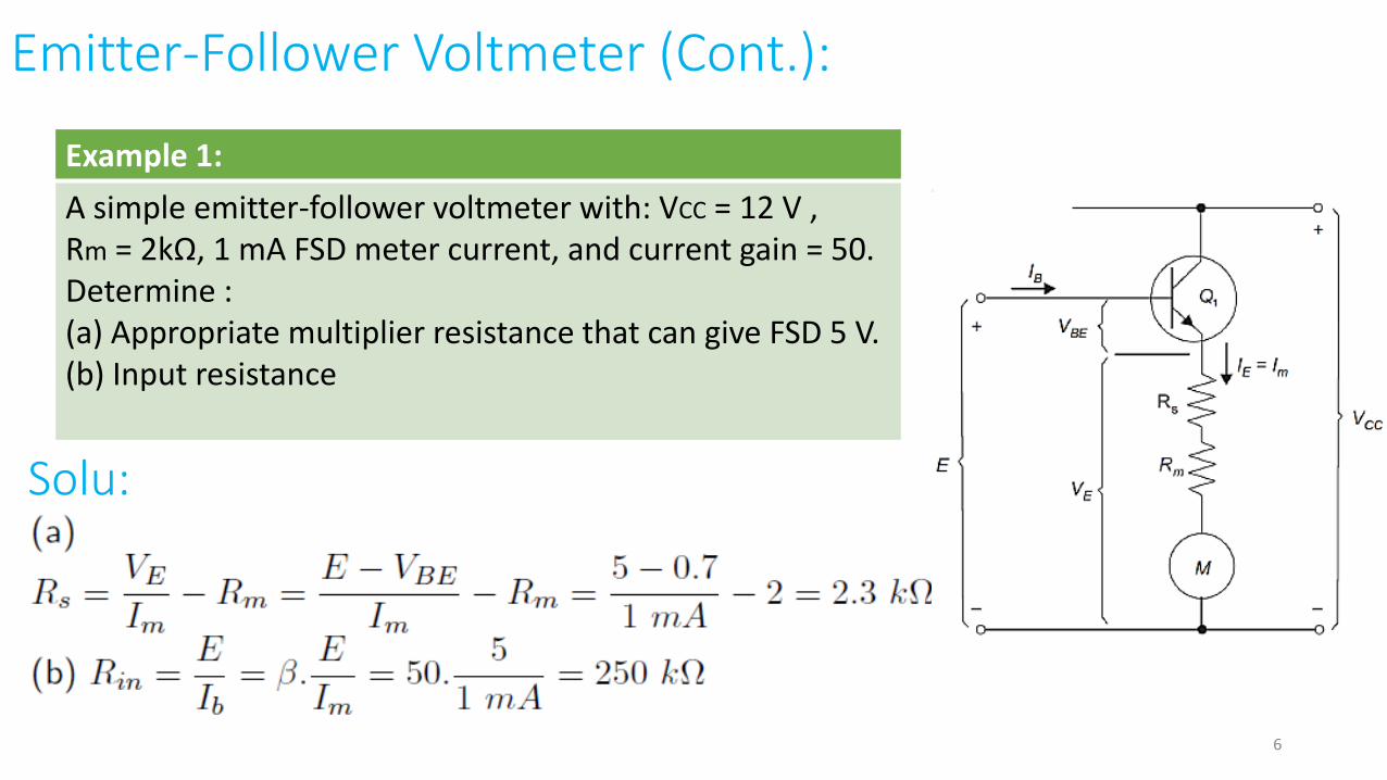
Example 1:
A simple emitter-follower voltmeter with: VCC = 12 V ,Rm = 2kΩ, 1 mA FSD meter current, and current gain = 50.Determine :(a) Appropriate multiplier resistance that can give FSD 5 V.(b) Input resistance
Solu:
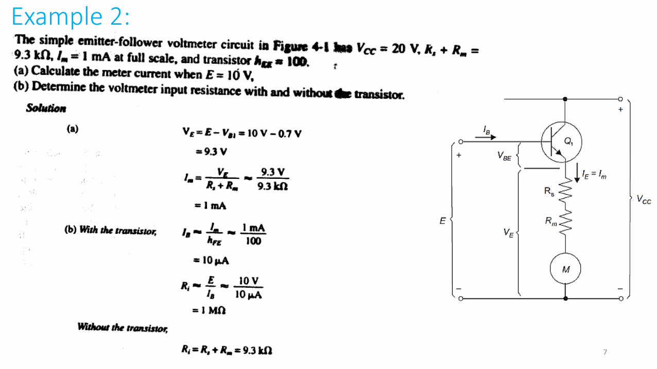
Example 2:
7

Emitter-Follower Voltmeter (Cont.) :
• To reduce the drop VBE, a one more emitter-follower and a voltage divider are used with a ± 12 V dual polarity supply is connected.
8
m
• When E = 0, the resistance R5 is adjusted to make VE2 = 0.7 and Vm = 0.
• When E is exist, the PMMC voltage is:
• So, the voltage drop is removed.

9
Example 3:

10

FET-input Voltmeter:
Advantage:
The Field Effect Transistor (FET) provide extremely high input resistance.
11

12
Example 4:

Operational Amplifier Voltmeter Circuits.
13

Operational Amplifier
14
The Op. Amp IC is a perfect choice to be used in the electronic voltmeters

Operational Amplifier Voltmeter
• The voltage follower has a much higher input resistance and lower output resistance than the emitter follower.
• The input voltage is applied to the op-amp noninverting input terminal, and the feedback from the output goes to the inverting input.
• The attenuator selects the voltmeter range.
15

IC Operational Amplifier
16
17
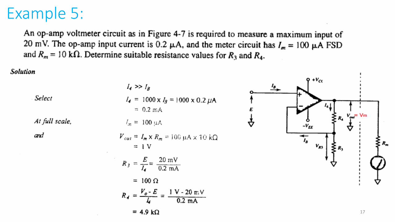
Example 5:

Voltage-to-current converter Voltmeter
• The
18

AC Electronic Voltmeters
19
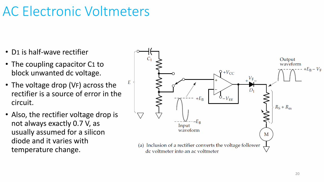
AC Electronic Voltmeters
• D1 is half-wave rectifier
• The coupling capacitor C1 to block unwanted dc voltage.
• The voltage drop (VF) across the rectifier is a source of error in the circuit.
• Also, the rectifier voltage drop is not always exactly 0.7 V, as usually assumed for a silicon diode and it varies with temperature change.
20

AC Electronic Voltmeters (Cont.)
• To avoid these errors, the voltage follower feedback connection to the inverting terminal is taken from the cathode of rectifier D1 instead of from the amplifier output.
21

AC Electronic Voltmeters (Cont.)
22
• The input is amplified by factor

23

24
Op-amp Half-bridge Rectifier Voltmeter

Voltmeter & Shunt
25

Multimeter Probes
26

Multimeter Probes
• There are many probes and adapters available to extend multimeterranges.
1. High-Voltage Probe
2. High-Current Probes
3. RF probe allows the meter to measure the voltage level of a waveform with a frequency upper its cutoff frequency.
27

28

29

30
DVM Outline:
1. Introduction.
2. Ramp Type Digital Voltmeters.
3. Dual Slope Digital Voltmeters.
4. DVM Range Changing.
5. Digital Voltmeter Accuracy.
6. Types of Digital Multi-meters.
31

Introduction:
• Two types will be covered: Ramp-typeand Dual slope Integrator DVMs.
• Digital voltmeters (DVM) are essentially analog-to-digital converters with digital displays to indicate the measured voltage.
Digital Voltmeter Basic Block Diagram32

Seven-Segment LED Display
There are two types:1. Common Anode2. Common Cathode
33

2. Ramp Type Digital Voltmeters
34

Ramp Type Digital Voltmeters:
• A ramp signal is generated.• The comparator compares the input
Vi with the ramp VR.
• If the comparator output V1 is high, the counting circuit will count the pulses from clock generator.
• If the output V1 is low, the counting will stop.
• Npulses / Vi .• The value of Vi will be displayed
35

Ramp Type Digital Voltmeters (Cont.):
36

Ramp Type Digital Voltmeters (Cont.):
The use of the Latch:
1. The latch isolates the display from the counting circuit during the t1.2. It will connect the display to the counting circuit at the rising edge of the comparator output.
37

End of Lecture
Best Wishes
38