Embed Size (px)
Citation preview
DR. HARVEV J, KARTEN, M.D. UNIVERSITY OF CALIFORNIA, SAN DIEGO DEPARTMENT OF NEUROSCIENCES, 0608 9500 GIU^AN DRIVE LA JOLLA, CA 92093-0608 February 1990
AXOCLAMP-2A MICROELECTRODE CLAMP
THEORY AND OPERATION
Written for Axon Instruments, Inc. by Alan Finkel, Ph.D.
Copyright 1988, 1990 Axon Instruments, Inc. No part of this manual may be reproduced, stored in a retrieval system, or transmitted, in any form or by any means, electronic, mechanical, photocopying, microfilming, recording, or otherwise, without written permission from Axon Instruments, Inc.
QUESTIONS? Call (415) 571-9400
Part Number 2500-000 REV B PriMcd in U.S.A.
O U T i ( r . . ; . , ) • • St^f 4 < i - . ^ ^
Ill
COPYRIGHT
THE CIRCUITS AND INFORMATION IN THIS MANUAL ARE COPYRIGHTED AND
MUST NOT BE REPRODUCED IN ANY FORM WHATSOEVER WITHOUT WRITTEN
PERMISSION FROM AXON INSTRUMENTS, INC.
VERIFICATION
THIS INSTRUMENT IS EXTENSIVELY TESTED AND THOROUGHLY CALIBRATED
BEFORE LEAVING THE FACTORY. NEVERTHELESS, RESEARCHERS SHOULD
INDEPENDENTLY VERIFY THE BASIC ACCURACY OF THE CONTROLS USING
RESISTOR/CAPACITOR MODELS OF THEIR ELECTRODES AND CELL MEMBRANES.
DISCLAIMER
THIS EQUIPMENT IS NOT INTENDED TO BE USED AND SHOULD NOT BE USED IN
HUMAN EXPERIMENTATION OR APPLIED TO HUMANS IN ANY WAY.
AXOCLAMP-2A THEORY & OPERATION, COPYRIGHT FEBRUARY 1990, AXON INSTRUMENTS, INC.
IV
Illustrations of the rear-panel view of the AX0CLAMP-2A are shown on the fold-out page at the rear of the manual.
AXOCLAMP-2A THEORY & OPERATION, COPYRIGHT FEBRUARY 1990, AXON INSTRUMENTS, INC.
9500 GILMAN DR VE ' " ' ' ' ^ ' ' ' ° ^ ° ^ LA JOLLA, CA 92093-0608
TABLE OF CONTENTS
Page
INTRODUCTION 1
FEATURES 3
FEATURES ..3
GLOSSARY 9
QUICK GUIDE TO OPERATIONS 11
DETAILED GUIDE TO OPERATIONS 15
ANTI-ALIAS FILTER 15
BATH PROBE i, 16
Bath Potential Measurement 16
Grounding 16
BLANKING 16
BRIDGE MODE 17
Description 17
Suggested Use 17
Intracellular Balancing 18
BUZZ 20
Remote Buzz 20
CALIBRATION SIGNAL 21
CAPACITANCE NEUTRALIZATION AND INPUT CAPACITANCE 21
Primary 21 Secondary 21
AXOCLAMP-2A THEORY & OPERATION, COPYRIGHT FEBRUARY 1990, AXON INSTRUMENTS, INC.
VI
Page
CLEAR 22
COMMAND GENERATORS 22
Step Conunand Generator 22
DC Command Generators 23
Extemal Conunand Inputs 23
Mixing Conunands. 23
CURRENT MEASUREMENT 25
DCC MODE 25
GROUNDING AND HUM 31
HEADSTAGES 32
The Meaning Of H 32
Which Headstage To Use .32
Capacitance Neutralization Range 34
7 Headstage Connectors 34
Tip Potentials - Detection 36
Tip Potentials - Prevention 37
Interchangeability 37
• Cleaning 37
Input Leakage Current And How To Trim It To Zero 37
Warning 38
DC Removal 38
Input Resistance ; 39
HOLDERS : .39
Features 39
Parts 40
Use 40
T IONOPHORESIS 42
A LINK-UP 42
AXOCLAMP-2A THEORY & OPERATION. COPYRIGHT FEBRUARY 1990, AXON INSTRUMENTS, INC.
Vll
Page
MICROELECTRODES FOR FAST SETTLING 43
Microelectrode Capacitance 43
Microelectrode Resistance 44
Filling Solutions.... 44
Recommended Reading 44
MODEL CELLS 45
The CLAMP-1 Model CeU 46
MONITOR 48
NOISE IN DCC AND dSEVC MODES 49
OFFSET CONTROLS 50
O U T P U T FILTER 50
High-Order Lowpass Filters For Low-Noise Recordings 51
Rise Time Of High-Order Filters 51
Note On Ultimate Rise Time ;.... 51
OUTPUT IMPEDANCE AND PROTECTION 51
PANEL METERS 51
V„(mV) 51
V2(mV) 52
I(nA) 52
PHASE • 52
POWER-SUPPLY GLITCHES 53
POWER SUPPLY VOLTAGE SELECTION & FUSE CHANGING 54
Supply Voltage 54
Changing The Fuse 54
REMOTE 55
RMP BALANCE 57
AXOCLAMP-2A THEORY & OPERATION, COPYRIGHT FEBRUARY 1990, AXON INSTRUMENTS. INC.
Vlll
Page
SERIES RESISTANCE 57
Origin 57
Problem 57
Solutions 57
What is Uie True Membrane Potential Time Course? 58
SEVC MODE - CONTINUOUS.... 60
Important Note - Anti-Alias Filter 60
Suggested Use 60
cSEVC Compared WiUi Whole-Cell Patch Clamp 62
SEVC MODE - DISCONTINUOUS .. . . .64
Description 64
Suggested Use 67
Important Note 70
Which SEVC to use witii a Suction Electrode 70
Minimum Sampling Rate and Maximum Gain 74
Clamp Error 74
Gain.... 74
SPACE CLAMP 75
TEN-TURN POTENTIOMETERS 75
TEVC MODE ; 75
Description 75
Suggested Use 76
Extremely Important Note - Coupling Capacitance 76
Saturation During The Capacitance Transient 79
Choosing the Microelectrode Resistances 79
TRIGGERED CLAMPING 79
TROUBLE SHOOTING 80
UNITY-GAIN RECORDING - THIRD POINT 80
AXOCLAMP-2A THEORY & OPERATION, COPYRIGHT FEBRUARY 1990, AXON INSTRUMENTS, INC.
IX
Page
VIRTUAL-GROUND CURRENT MEASUREMENT 80
10.V„ AND I^ OUTPUTS 81
SPECIFICATIONS 82
REFERENCES A-1
WARRANTY B-1
RMA FORM C-1
POLICY STATEMENT D-l
SERVICE D-l
COMMENT FORM E-1
FRONT AND REAR PANEL - f^ir^yf' i Z ^ ^ f ^ I f f f f ^ ^ P
AXOCLAMP-2A THEORY & OPERATION, COPYRIGHT FEBRUARY 1990, AXON INSTRUMENTS, INC.

CThis page ia intentionally left blank)
AXOCLAMP-2A THEORY & OPERATION, COPYRIGHT FEBRUARY 1990, AXON INSTRUMENTS, INC.
iNTRODUcrroN Page 1
INTRODUCTION
! The AXOCLAMP-2A Microelectrode Clamp can be used as a dual channel microelectrode probe, or as a microelectrode voltage clamp.
Voltage clar; ping is a powerful technique for the control of membrane potential and for the investigation of processes alfecting membrane conductance. Voltage clamping has traditionally been performed using two intracellular microelectrodes and the AXOCLAMP-2A can be used for this purpose.
The AXOCLAMP-2A can also be used for discontinuous single-electrode voltage clamping (dSEVC) and for continuous single-electrode voltage clamping (cSEVC). A single-electrode voltage clamp (SEVC) is more convenient to use than a two-electrode voltage clamp (TEVC) in very small cells and cells which cannot be visualized. A particular advantage of a dSEVC is that the voltage drop due to current flow through the series component of cell membrane resistance (Rg) is not clamped. In addition, for both types of SEVC instabilities due to coupling capacitance and coupling resistance between two microelectrodes do not arise.
The disadvantages of a dSEVC compared with a TEVC are that the response speed is slower, the maximum achievable gain is lower, and the noise in the current and voltage records is greater. The design of the AX0CLAMP-2A reduces these disadvantages towards their theoretical minimums, thereby allowing single-electrode voltage clamping to be performed in the many situations where conventional voltage clamping is not suitable.
A cSEVC i.s as low in noise as a TEVC but has a severe disadvantage in that the voltage drop across the microelectrode is clamped unless compensation is made. Since the required compensation is never perfect, tha rSF,V(; y in nnly he. psfid wh -ij thg e|ectrode resistance is very small compared with the cell input resistance. These favorable conditions can often be achieved by the whole-cell patch technique.
Because of the AXOCLAMP-2A's advanced design, it itself does not limit the achievable performance. Instead, the dominant factor affecting SEVC performance is the microelectrode. Users of the AXOCLAMP-2A in eidier of the SEVC modes should be quick to question, then adjust, the microelectrode and its placement.
TTie AXOCLAMP-2A is a sophisticated instrument. Even experienced researchers are advised to read this manual thoroughly and to familiarize themselves widi the instrument using model electrodes (i.e. resistors) and cells (e.g. parallel RC) before attempting experiments with real microelectrodes and cells.
We will be pleased to answer any questions regarding the theory and use of the AX0CLAMP-2A. Any conmients and suggestions on the use and design ofthe AX0CLAMP-2A will be much appreciated.
We would be most grateful for reprints of papers describing work performed with the AX0CLAMP-2A. Keeping abreast of research performed helps us to design our instruments to be of maximum usefulness to you who use them.
Axon Instruments, Inc.
AX0CLAMP-2A THEORY & OPERATION, COPYRIGHT FEBRUARY 1990, AXON INSTRUMENTS, INC.

Page 2 iNTRODUcnoN
(This page is intentionally left blank)
AXOCLAMP-2A THEORY & OPERATION, COPYRIGHT FEBRUARY 1990, AXON INSTRUMENTS, INC.
FEATURES Page 3
FEATURES
The AXOCLAMP-2A is a complete microelectrode current and voltage clamp for intracdiular investigations. It combines state-of-the-art single-electrode voltage clamping, two-electrode voltage clamping, and two complete bridge amplifiers into one instrument. Precision command voltages, meters, filters, offsets and many other features are built in to give you unprecedented flexibility.
4 discontinuous single-electrode voltage clamping 4 continuous single-electrode voltage clanqiing 4 two-electrode voltages clamping 4 discontinuous current clamping 4 two complete bridge amplifiers 4 high-speed headstages 4 low-noise low-hum operation 4 push-button selection of operating mode 4 computer selection of operating mode 4 two digital meters for voltage display 4 digital counter for display of sample rate 4 3-input digital meter for current display 4 separate current-measurement circuits for
each microelectrode 4 virtual-ground current measurement
4 bath potential measurement and compensation 4 intemally generated precision command voltages 4 automatic clamping at resting membrane potential 4 offset compensation 4 rejection of stimulus artifacts 4 output bandwidth selection 4 calbration signal on outputs 4 electrode buzz 4 electrode clear 4 hands-free operation of buzz and clear 4 anti-alias filter 4 phase control 4 sampling clock synchronization 4 model cell
VOLTAGE CLAMPING Voltage clamp with one or two microelectrodes — your choice is dictated by the needs of your investigation; the AXOCLAMP-2A does both. Discontinuous Single-Electrode Voltage Clamping (dSEVC) is based on the technique of sampling the membrane potential while zero current flows and then retaining this sampled value while current is injected into the cell. This procedure is rapidly repeated to produce a smooth response. Continuous Single-Electrode Voltage Clamping uses a low resistance electrode to continuously record membrane potential and inject current. The error caused by voltage drop across the electrode resistance can be partially reduced by series resistance compensation. With Two-Electrode Voltage Clamping (TEVC) one microelectrode is used to continuously record membrane potential while the other is used to inject current. ~ ^
Gain of the voltage-clamp amplifier is quickly set on a smooth-acting nonlinear control. The phase response of the amplifier is altered from lead to lag by a Phase Shift potentiometer with a Center Frequency switch to select the range.
A unique variable Anti-Alias Filter helps reduce noise towards the theoretical minimum during dSEVC by slowing the response of the sampling circuit to suit the sample rate and the microelectrode response. The Sample Rate can be continuously altered from a low value of 500 Hz to a high of SO kHz. This enables you to take advantage of the decrease in noise and response times occurring when faster sampling rates are used.
AXOCLAMP-2A THEORY & OPERATION, COPYRIGHT FEBRUARY 1990, AXON INSTRUMENTS, INC.
Page 4 FEATURES
The sample clocks of two AXOCLAMP-2A's can be synchronized in a 'Master-Slave' configuration. This is useful in experiments in which two cells in the same preparations are independently voltage clamped using dSEVC. Linking the two clocks prevents the generation of spurious signals which would otherwise appear at harmonics of the difference in the two clocks firequencies.
Output compliance in TEVC mode is ±30 V. This reduces the chance of saturation while the membrane capacitance is charging after a step change in voltage. To further minimize the chance of saturation during TEVC a relay-switched headstage (HS-4) is available to automatically bypass the current-sensing resistor inside the headstage. The HS-4 headstage must therefore be used in conjunction with a virtual-ground current monitor (VG-2). The HS-4 headstage is recommended only when large, ultra-fast voltage steps in big cells must be established.
Another unique control is a Resting Membrane Potential (RMP) Balance Indicator which enables you to preset the clamp offset so that when you switch into voltage-clamp mode the cell membrane will automatically be clamped at its resting value, irrespective of the clamp gain.
A remarkable "BLANK" facility can be used to force the voltage clamp system to ignore stimulus artifacts that would otherwise be picked up by the voltage-recording circuit and result in large current artifacts which could damage the cell under clamp.
A "Monitor" output enables the input to the sampling circuit to be observed. It is essential to observe this signal during dSEVC to ensure that the microelectrode voltage due to current passing has time to adequately decay at the end of each cycle. An oscilloscope trigger signal at the sample rate is provided for use with the Monitor signal.
The AX0CLAMP-2A allows very fast discontinuous single-electrode voltage clamping. In a test cell (see specifications) the 10% to 90% rise time is only 100 /ts. In a real setup the response speed is limited by the microelectrode characteristics, but membrane potential rise times (without overshoot) of less than 1 ms have been regularly achieved in a variety of cell types. Two-electrode voltage clamping is much faster.
CURRENT CLAMPING Two controls for each microelectrode are devoted to clearing blocked microelectrode tips and assisting cell penetration. One is a "Clear" switch which can be used to force large hyperpolarizing or depolarizing currents through the microelectrode. The other is a "BUZZ" switch which causes the mocroelectrode voltage to oscillate. Depending on the microelectrode and the preparation, one of these two methods will often succeed in lowering the resistance of blocked microelectrode tips. When used while the tip of the microelectrode is pressing against the membrane, Buzz and Clear may also cause the microelectrode to penetrate the cell.
AXOCLAMP-2A THEORY & OPERATION, COPYRIGHT FEBRUARY 1990, AXON INSTRUMENTS, INC.
FEATURES Page 5
HEADSTAGES Unity-voltage-gain HS-2 headstages are available in several current gains. These cover the range of cell input impedances from less than 1 MO to greater than 1 GO. Ultrahigh-input impedance versions are also available for ion-sensitive electrodes.
High speed and low noise are achieved by using bootstrapped power supplies for the input circuit of each headstage. These bootstrapped power supplies are derived from special high-voltage circuits so that the headstages will not be saturated by the large voltages that may occur during the passage of ciurent through high-resistance microelectrodes. Capacitance Neutralization is also derived from high-voltage circuits so that fast responses are not degraded during large input signals.
Current in each microelectrode is continuously measured during both voltage clamp and current clamp. This measurement does not include currents from sources other than the microelectrode (e.g. hum, ionophoresis, the other microelectrode) and indicates zero if the microelectrode blocks.
Headstages have a gold-plated 2 mm (0.08") input socket to directly accept standard microelectrode holders. 2 mm plugs are supplied with the headstages to connect wire leads, if used.
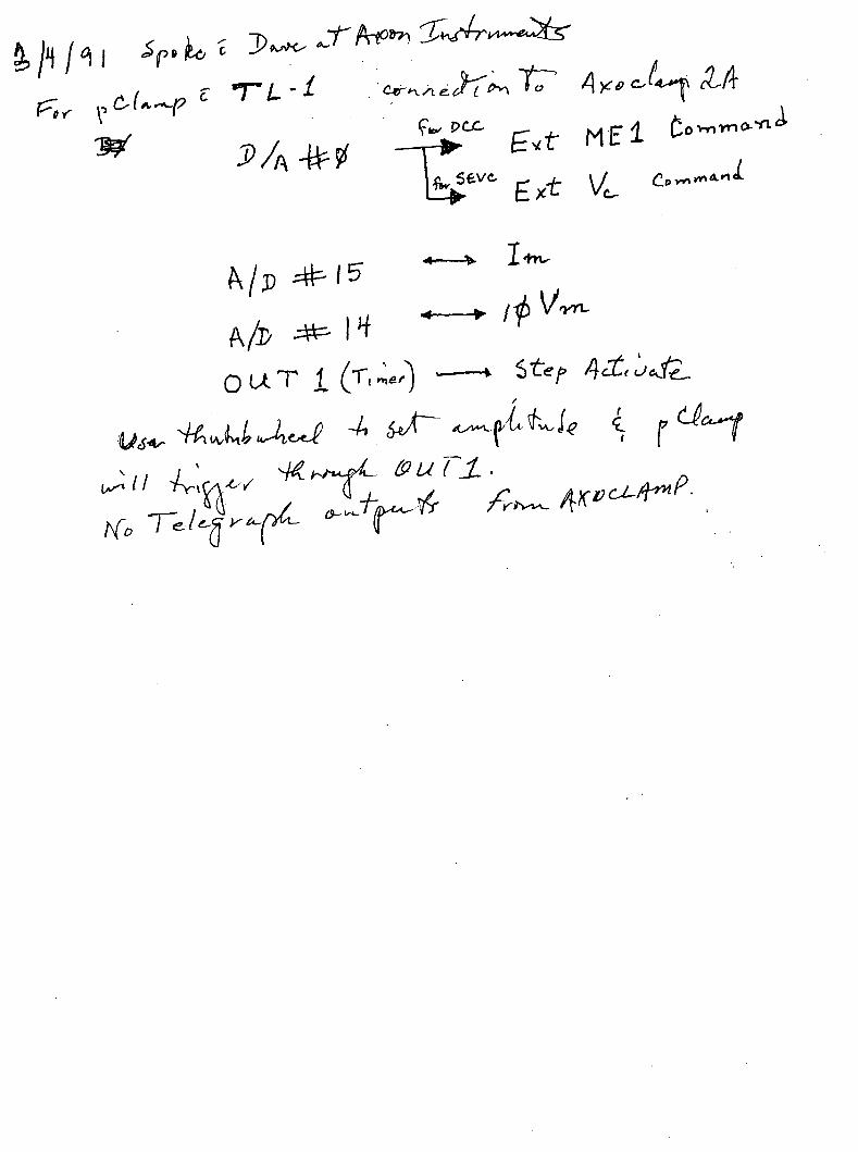
COMMAND GENERATORS In any mode, level and step commands can be generated intemally. Level Commands (one for voltage clamp and one for each microelectrode for a total of 3) are set on precision ten-tum potentiometers. The Step Command is set on a 3'/i-digit thumbwheel switch and can be directed to either one of the microelectrodes or to the voltage clamp. An indicator light for each microelectrode illuminates during current commands. Extemal command sources can be used simultaneously with the intemal command sources.
OUTPUTS Two dedicated Digital Voltmeters continuously display the microelectrode voltages while a third displays the currmt in the selected microelectrode or in a virtual-ground circuit, if used. Front-panel controls for each microelectrode and the virtual ground set the scaling of the current meter to suit the gain of your headstage.
A Digital Counter lets you know precisely what sampling rate you are using during single-electrode voltage clamp or discontinuous current clamp.
Offset Controls are provided for each microelectrode, and a variable Lowpass Filter is provided for the microelectrode used in single-electrode voltage clamping. As well, an intemally generated Calibration Signal can be superimposed onto each of the outputs. Hence, the output signals in many cases can be wholly conditioned within the AXOCLAMP-2A to suit your recording apparatus.
AXOCLAMP;2A THEORY & OPERATION, COPYRIGHT FEBRUARY 1990, AXON INSTRUMENTS, INC.
Page 6 FEATURES
Six outputs are conveniently located at the front panel for connectmg to your oscilloscope. These outputs are repeated at the rear panel, where the other outputs, the inputs and the headstage connectors are also located.
REMOTE CONTROL Hands-free operation of Buzz is possible using the footswitches supplied with every AXOCLAMP-2A. Selection of the operating mode can be made remotely for computer sequencing of experiments.
All AXOCLAMP-2AS have a Buzz oscillator to assist in cell penetration. The duration of the Buzz oscillation is normally equal to the time that the front-panel switch is pressed. Practically, the shortest duration that this switch can be pressed is about 100 ms. For small cells, 100 ms Buzz oscillation sometimes damages the cells immediately after penetration.
The Remote Buzz Duration Control supplied with the AX0CLAMP-2A is a hand held control that contains a trigger switch to buzz either electrode, and a duration control for setting the Buzz duration in the range 1-50 ms. An appropriate duration can be fotmd for most cells that is sufficiently long to allow penetration of the membrane but short enough that the cell is not damaged after penetration.
MODEL CELL Every AXOCLAMP-2A is supplied with a CLAMP-1 model cell. This model cell plugs directly into the input sockets of the headstages. A switch allows the CLAMP-1 model cell to be configured as (a) BATH mode — two 50 MQ electrodes to ground, or (b) CELL mode — two electrodes connected to a 50 MO // 500 pF cell.
The CLAMP-1 model cell can be used to test and practice using bridge current clamp, discontinuous current clamp, single-electrode voltage clamp and two-electrode voltage clamp. It is a useful tool to use while leaming the operation of the AX0CLAMP-2A and subsequently to verify the correct operation of the AXOCLAMP-2A and the recording pathway.
GENERAL A third HS-2 headstage can be used extracellulariy to record bath potential. The bath potential is then subtracted from the potentials recorded by the two intracellular microelectrodes to compensate for shifts in bath potential due to changing of solutions or temperature.
A VG-2 Virtual-Ground headstage may be used to measure total bath current. Generally, the built-in current monitors are more useful since they yield the microelectrode currents separately without any interfering currents (e.g. from ionophoresis). Since both microelectrode amplifiers are complete, one microelectrode can be used for ionophoresis while the
AXOCLAMP-2A THEORY & OPERATION, COPYRIGHT FEBRUARY 1990, AXON INSTRUMENTS, INC.
FEATURES Page?
other is used intracellularly. Internally generated hum due to the built-in power supply has been prevented by using a specially constmcted low-radiation transformer, by placing the supply well away from the rest of the circuitry, and by using intemal shielding. The incoming power is filtered to remove radio-frequency interference (RFI).
QUALITY The excellence of the components and constmction will be obvious to you from the high quality of the cabinet and controls. Precision ten-tura potentiometers and reliable switches abound. But the high qualify is more than "skin deep' gold plated connectors ar^ used throughout, ultralow-drift operational amplifiers are used in all critical positions, I.C.s are socketed for easy maintenance, and the circuit designs and operation have been well tested in laboratories throughout the world. All this adds up to low-noise, low-drift, reliable and accurate operation. And the excellence does not stop with the hardware. We also provide a detailed operator's manual that serves as a handbook of procedures for microelectrode users. A separate service manual is also supplied.
FURTHER INFORMATION AND ORDERING The AXOCLAMP specification sheet contains complete technical details
and ordering information. Please call the factory for answers to any questions you may have.
AXOCLAMP-2A THEORY & OPERATION, COPYRIGHT FEBRUARY 1990, AXON INSTRUMENTS, INC.
Pages FEATURES
Crhis page is intentionally left blank)
AXOCLAMP-2A THEORY & OPERATION, COPYRIGHT FEBRUARY 1990, AXON INSTRUMENTS, INC.
GLOSSARY Page 9
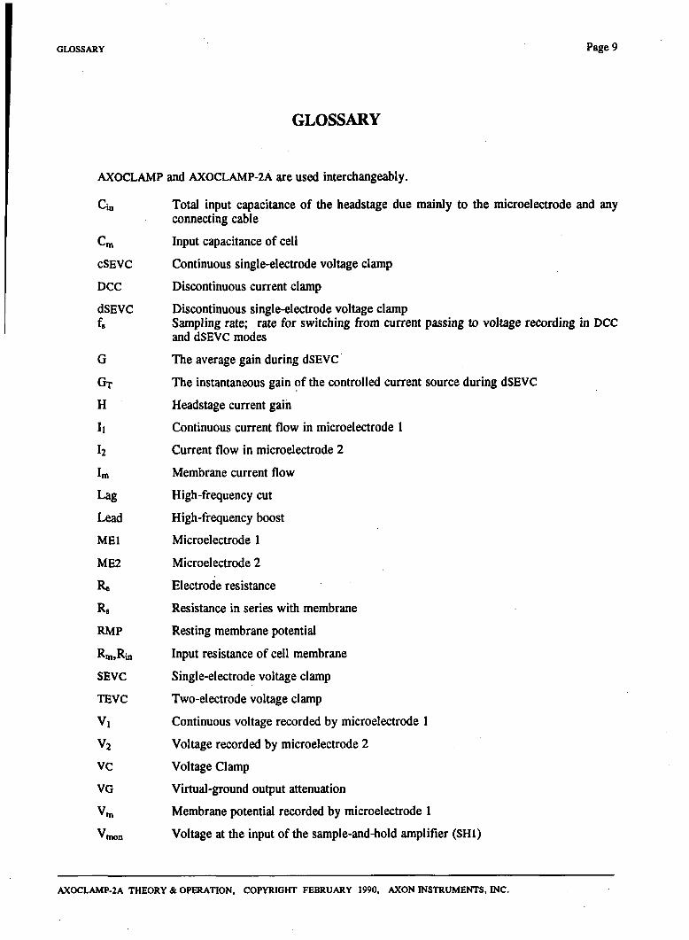
GLOSSARY
AXOCLAMP and AX0CLAMP-2A are used interchangeably.
Cia Total input capacitance of the headstage due mainly to the microelectrode and any connecting cable
Cm Input capacitance of cell
cSEVC Continuous single-electrode voltage clamp
DCC Discontinuous current clamp
dSEVC Discontinuous single-electrode voltage clamp fg Sampling rate; rate for switching from current passing to voltage recording in DCC
and dSEVC modes
G The average gain during dSEVC
GT The instantaneous gain of the controlled current source during dSEVC
H Headstage current gain
11 Continuous current flow in microelectrode 1
12 Current flow in microelectrode 2
Im Membrane current flow
Lag High-frequency cut
Lead High-frequency boost
MEI Microelectrode 1
ME2 Microelectrode 2
Re Electrode resistance
Rg Resistance in series with membrane
RMP Resting membrane potential
Rm.Rin Input resistance of cell membrane
SEVC Single-electrode voltage clamp
TEVC Two-electrode voltage clamp
Vl Continuous voltage recorded by microelectrode 1
Vj Voltage recorded by microelectrode 2
VC Voltage Clamp
VG Virtual-ground output attenuation
Vm Membrane potential recorded by microelectrode 1
Vmon Voltage at the input of the sample-and-hold amplifier (SHI)
AX0CLAMP-2A THEORY & OPERATION, COPYRIGHT FEBRUARY 1990, AXON INSTRUMENTS, INC.

Page 10 GLOSSARY
Crtiis page is intentionally left blank)
AXOCLAMP-2A THEORY & OPERATION, COPYRIGHT FEBRUARY 1990, AXON INSTRUMENTS, INC.
QUICK GUIDE TO OPERATIONS Page 11
QUICK GUIDE TO OPERATIONS
The controls and operation of die AXOCLAMP-2A are very briefly described in this section. Detailed explanations are given in the alphabetically organized Section E of this manual.
Dl . HEADSTAGES
(1) HS-2 Series HS-2 series headstages are standard. Two supplied with AX0CLAMP-2A.
All HS-2 headstages record voltage at unity gain. Z ' i . ^ . K [J> C C ^^^-M- j
Available in several headstage current gains (H). Front-panel controls read direcdy in indicated units when H = xl . All H values are powers of 10. Small H values used widi high-resistance cells and electrodes. Large H values used to pass large curretits.
H = xlO, xl , xO.l, xO.Ol for recording and clamping. H = 0.0001 for ion-sensitive electrodes.
Headstages normally supplied in L version (low-noise, low capacitance-neutralization range). M version can be supplied to compensate large capacitance of grounded shield.
Red connector: Microelectrode input Gold Connector: Driven shield; case Yellow connector: Ground output
(2) HS-4 Series Optional for current-passing electrode (ME2) in two-electrode voltage clamp. (Requires VG-2 for current measurement.) Bypasses internal current-setting resistor during two-electrode voltage clamp so output voltage appliad directly to electrode.
Supplied in L or M versions only.
When AX0CLAMP-2A is not in two-electrode voltage clamp mode HS-4 operates same as HS-2.
(3) VG-2 Series Optional virtual-ground headstage measures total badi current. Not required for normal operation. Required in two-electrode voltage clamp if HS-4 headstage used. Virtual Ground output attenuation (VG) specifies the sensitivity. Smaller VG is more sensitive; used for low currents.
AXOCLAMP-2A THEORY & OPERATION, COPYRIGHT FEBRUARY 1990, AXON INSTRUMENTS, INC.
Page 12 QUICK GUEIE TO OPERATIONS
D2. MODE GROUP
Illuminated pushbuttons reconfigure AXOCLAMP-2A for different operating modes.
BRIDGE: Two conventional microelectrode amplifiers.
DCC: Discontinuous current clamp on microelectrode 1.
SEVC: Single-electrode voltage clamp on microelectrode 1.
Discontinuous SEVC (dSEVC) uses time-sharing technique (electrode switches repetitively from voltage recording to current-passing).
Continuous SEVC (cSEVC) is .analogous to whole-cell patch clamp (electrode simultaneously does voltage recording and current passing).
TEVC: Two-electrode voltage clamp. Microelectrode 1 does voltage recording. Microelectrode 2 does current passing. -——- - . - •
Cont./Discont.: Switch and lamps operate only in SEVC mode.
D3. MICROELECTRODE 1 (MEI) GROUP
Complete intracellular/extracellular electrometer.
Capacitance Neutralization:
Buzz:
Bridge:
Input Offset:
DC Current Command:
Clear:
Voltmeter:
Neutralizes electrode input capacitance. Clockwise rotation reduces effective input capacitance and speeds response. Overutilization oscillates headstage.
Deliberate overutilization of capacitance neutralization. Oscillation helps cell penetration. Footswitches supplied as standard accessories.
Compensates electrode voltage drop during current passing. Resistance (scaled by H) read on ten-tum dial. Range automatically reduced tenfold during cSEVC.
Adds ±500 mV DC to electrode voltage at early stage, electrode voltage while extracellular.
Use to zero
For injection of j^nsjant current. Magnitude set on ten-tum dial. Polarity set on switch. LED indicates when current injection activated.
Passes large hyperpolarizing and depolarizing current to clear blocked electrodes or help cell impalement.
Indicates membrane potential (Vm) in mV.
D4. MICROELECTRODE 2 (ME2) GROUP
An independent intracellular/extracellular electrometer similar to MEI. Differences are:
Potential is labelled V2.
Output offset adds ±500 mV to electrode voltage in output stage.
AXOCLAMP-2A THEORY & OPERATION, COPYRIGHT FEBRUARY 1990, AXON INSTRUMENTS, INC.
QUICK GUIDE TO OPERATIONS Page 13
D5. VOLTAGE-CLAMP GROUP
Gain:
Holding Position:
RMP Balance Lamps:
Phase shift:
Anti-Alias Filter:
Sets open-loop gain during voltage clamp. In SEVC modes output is current source. Therefore gain is nA/mV. In TEVC mode ou^ut is voltage source. Therefore gain is V/V.
Sets holding potential during voltage clamp. Range ±200 mV.
Null during Bridge or DCC so that when activated, voltage clamp will be at resting membrane potential.
Modifies frequency response of voltage-clamp amplifier. Compensates for nonideal phase shifts of membrane. Potentiometer adds phase advance Oead) or phase delay Gag). Switch selects range.
Used in DCC or dSEVC modes to reduce noise of electrodes that have fast and slow setding characteristics.
D6. STEP-COMMAND GROUP
Uses D/A converter to generate precision command voltage.
Destination Switch:
Thumbwheel Switch:
Ext./Cont./Off Switch:
Indication:
Selects voltage clamp or either microelectrode as target for command. Commands are mV or nA respectively.
Sets magnitude widi 0.05% resolution.
Cont. position activates step command. Ext. position thumbwheel switch is off unless logic level HIGH applied to rear-panel Step Activate input. Off position overrides logic input.
When destination is a microelectrode and step command is activated, lamp in microelectrode DC Current Command Section illuminates.
D7. RATE GROUP
Counter indicates sampling rate (cycling rate) in DCC and dSEVC modes.
Potentiometer adjusts rate from 500 Hz to 50 kHz.
AXOCLAMP-2A THEORY St OPERATION, COPYRIGHT FEBRUARY 1990, AXON INSTRUMENTS, INC.
• v 7
Page 14 QUICK GUIDE TO OPERATIONS
D8. INPUTS AND OUTPUTS
Vm, Im Output Bandwiddi switch selects -3 dB frequency of single-pole lowpass on Im and 10. Vm outputs.
Current G) voltmeter displays DC current from eidier microelectrode or virtual ground if used. Switch used to select meter input. Decimal point set on Hi, H2 or VG switches.
All BNC inputs and outputs located on rear panel. Frequendy used outputs repeated on front panel.
Im output: Membrane current recorded by MEI.
11 Cont. Output: MEI current (equals Im in Bridge, cSEVC and TEVC modes).
12 output: ME2 current.
IviRT output: Virtual-ground current.
10.Vm output: Membrane potential recorded by MEI; gain of 10.
Vl Cont. output: Instantaneous MEI potential. No Bridge Balance.
Monitor output: Input of sample-and-hold amplifier. Should be observed on second
oscilloscope during DCC and dSEVC modes.
V2 output: ME2 potential. Includes Bridge Balance.
Sample Clock output: Logic-level pulses at the sample rate; used to trigger monitor oscilloscope.
VBATH output: Potential recorded by bath electrode.
Cal. Activate input:. Logic HIGH on this input puts calibration voltage proportional to thumbwheel
setting onto voltage and current outputs.
Step Activate input: Logic HIGH activates Step Command.
Blank Activate input: Logic HIGH activates Blank. During Blank, Vm prevented from updating.
Thus stimulus artifacts are rejected.
Ext. VC Command input: Voltage on this input converted into voltage-clamp command.
Ext. MEI Command input: Voltage on this input converted into MEI current command.
Ext. ME2 Command input: Voltage on this input converted into ME2 current command.
R» Comp. input: Used to compensate voltage drop across membrane R, during TEVC. Not normally required. See service manual for suggested circuit.
VBATH IN input: Bath potential recorded by other equipment subtracted from Vi and V2 if connected to this input.
D9. REMOTE
Allows certain functions to be remotely activated by computer or switches. These are Mode, Buzz and Clear.
DIG. CLOCK LINK-UP
Allows sampling clocks from two AX0CLAMP-2AS to be synchronized. This eliminates electrode crosstalk when two AXOCLAMP-2As in dSEVC mode used to clamp two cells in same preparation. Requires LU-1 link-up cable.
AXOCI-AMP-2A THEORY & OPERATION, COPYRIGHT FEBRUARY 1990, AXON INSTRUMENTS, INC.
DETAILED GUIDE TO OPERATIONS Page 15
DETAILED GUIDE TO OPERATIONS
ANTI-ALIAS FILTER
A property of all digital sampling systems is that noise in the input signal at frequencies greater than 0.5 of die sample rate (fg) is folded down to appear as extra noise in the bandwidth from zero to 0.5 of fg (see section on noise). This phenomenon is known as aliasing.
Aliasing can be overcome by filtering die input signal before sampling, thereby reducing die high-frequency noise content. However, this filtering procedure degrades the dynamic response of the input signal and when used with an ideal microelectrode worsens the clamp performance.
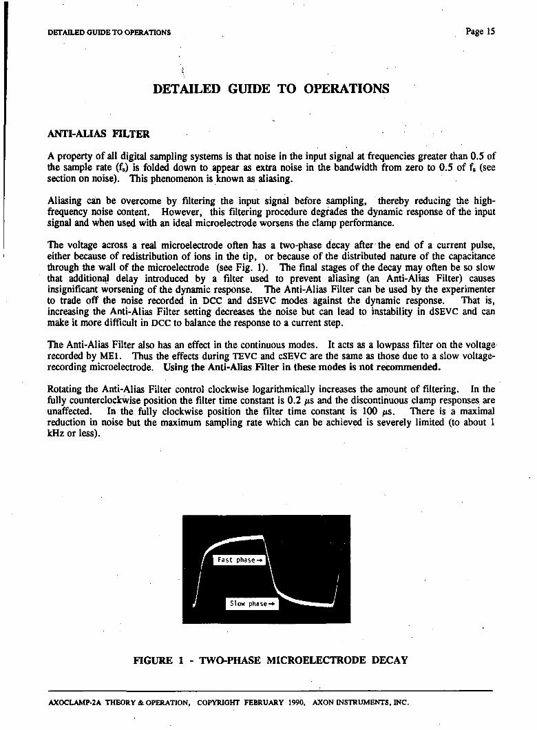
The voltage across a real microelectrode often has a two-phase decay after the end of a current pulse, either because of redistribution of ions in the tip, or because of the distributed nature of the capacitance through the wall of the microelectrode (see Fig. 1). The final stages of the decay may often be so slow that additional delay introduced by a filter u s ^ to prevent aliasing (an Anti-Alias Filter) causes insignificant worsening of the dynamic response. The Anti-Alias Filter can be used by the experimenter to trade off the noise recorded in DCC and dSEVC modes against the dynamic response. That is, increasing the Anti-Alias Filter setting decreases the noise but can lead to instability in dSEVC and can make it more difficult in DCC to balance the response to a current step.
The Anti-Alias Filter also has an effect in the continuous modes. It acts as a lowpass filter on the voltage recorded by MEI. Thus the effects during TEVC and cSEVC are the same as those due to a slow voltage-recording microelectrode. Using the Anti-Alias Filter in these modes is not recommended.
Rotating the Anti-Alias Filter control clockwise logarithmically increases die amount of filtering. In the fully counterclockwise position the filter time constant is 0.2 ;xs and the discontinuous clamp responses are unaffected. In the fiiUy clockwise position the filter time constant is 100 /iS. There is a maximal reduction in noise but the maximum sampling rate which can be achieved is severely limited (to about 1 kHz or less).
FIGURE 1 - TWO-PHASE MICROELECTRODE DECAY
AXOCI-AMP-2A THEORY & OPERATION, COPYRIGHT FEBRUARY 1990, AXON INSTRUMENTS, INC.
Page 16 DETAILED GUIDE TO OPERATIONS
BATH PROBE
Bath Potential Measurement
In certain experimental circumstances it is desirable to make all voltage measurements relative to a reference point in the bathing solution radier than relative to ground. (These conditions may include precision measurements during changes of temperature or ion content of the saline, or cases of restricted access from the extracellular space to the grounding point.)
All measurements are normally made relative to the system ground. However, if an HS-2 headstage is plugged into the rear-panel Bath Probe connector, measurements by both MEI and ME2 are automatically made relative to the potential recorded by this headstage. For optimum voltage-clamp performance, the bandwidth of die bath potential is limited to 300 Hz before it is subtracted from the potentials recorded by MEI and ME2 (see Finkel & Gage, 1985). The bath microelectrode cannot be used for current passing.
The fiill-bandwiddi voltage recorded by die badi microelectrode is available at the VBATH OUT connector.
If there is no HS-2 headstage plugged into the Bath Probe connector, a reference potential from an external amplifier can be subtracted by connecting a reference source to the VBATH IN connector.
Grounding
It is quite uncommon to measure the bath potential. Irrespective of whether or not the bath potential is measured, the preparation bath should be grounded by direcdy connecting it to the yellow ground connector on the back ofthe MEI headstage (or to a virtual-ground headstage if used).
BLANKING
A common problem when using stimulating electrodes is that some of the stimulus is direcdy coupled into the recording microelectrode. This can saturate subsequent high-gain amplifiers and die coupling capacitors of AC circuits. The saturation effects may take tens or hundreds of milliseconds to subside. The best way to minimize or even eliminate this artifact is at the source, by using small stimuli, isolated stimiilators, placing an grounded shield between the stimulating electrodes and the microelectrodes, etc. Often, though, it is not possible to reduce the artifact to manageable levels.
The AXOCLAMP-2A can circumvent the effects of the stimulus artifact by Blanking. At the moment the logic level of the Blank Activate input goes HIGH the value of Vm is sampled and saved. For the duration ofthe HIGH signal, this saved value is used instead ofthe actual potential.
In voltage-clamp modes the voltage-clamp current during the Blanking period will be held at the level which existed at the start of the period. A small deviation from the command potential may develop during the Blanking period as a result of comparing the command to the sampled value of Vm instead of the instantaneous value of Vm. This deviation will only be seen when the Blanking period ends. Usually this deviation is preferable to the situation that can occur if Blanking is not^used. If Blanking is not used the artifact pick^ up by MEI is treated by the voltage-clamp circuit as an attempt by the cell to change its potential. Therefore, the voltage-clamp circuit causes a current to be passed into the cell to clamp this presumed membrane potential change. If the stimulus artifact is large, the consequent current artifact can be large enough to damage the cell.
AXOCLAMP-2A THEORY & OPERATION, COPYRIGHT FEBRUARY 1990, AXON INSTRITMENTS, INC.
DETAILED GUIDE TO OPERATIONS Page 17
The width of the Blanking period should be no longer than the minimum width required to cover the period of the stimulus artifact. It is important not to Blank for longer than necessary since during Blanking no updating of Vm is allowed. Even when Blanking is used, attempts should still be made to minimize the artifact at the source.
BRIDGE MODE
Description
In Bridge mode the microelectrode voltages are monitored continuously, and continuous currents can be injected down MEI or ME2.
Associated with the current flow (I) in a microelectrode is a voltage drop across the microelectrode which depends on the product of the current and the microelectrode resistance (Re)- This unwanted IR voltage drop adds to the recorded potential. The Bridge Balance control can be used to balance out this voltage drop so that only membrane potential is recorded. The term "Bridge" refers to the original Wheatstone Bridge circuit used to balance the IR voltage drop and is retained by convention even though die circuitry has been r^laced by operational amplifier techniques.
The particular setting required to balance the Bridge is aJmeasure^Qhe-microelectrodTiresistance. j =• /\
In cSEVC mode the Bridge potentiometer compensates electrode IR voltage drop at one-tenth sensitivity.
Suggested Use
Set die Destination switch to ME 1/2 and externally trigger die Step Command generator so that ^uls^ of current are repetitively injected into MEl/2. (Altematively, derive the command for injecting current pulses by connecting a signal source to the Ext. ME 1/2 Command input.) Start with the Bridge Balance control set to zero. Advance the dial until the fast voltage steps seen at die start and finish of the current step are just eliminated. The Bridge is correcdv balanc^. The residual transient at the start and finish of the current step is due to the finite response speed of'the ihicroelectrode. No attempt is made to balance this transient since it covers a very brief period only and it is a useful indication of the frequency response of the microelectrode. The transient can be minimized by correcdy setting the Capacitance Neutralization.
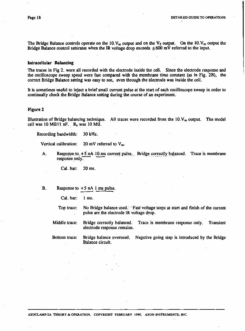
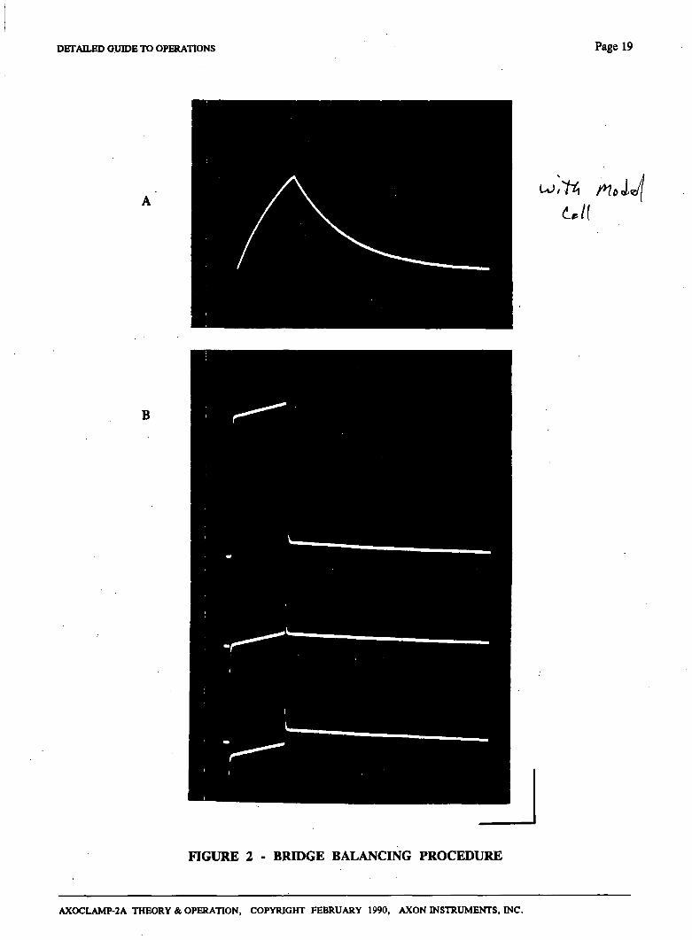
The Bridge balancing procedure is illustrated in Fig. 2. The trace in A was recorded in a_model cell when the Bridge Balance control was correctly set. In response to a positive current pulse the membrane potential began to charge up. Before the membrane potential reached its final value die current pulse was terminated and the membrane potential exponentially decayed to its final value.
Hie traces in B were recorded at a sweep speed which was fast compared with the membrane time constant, hence the membrane responses look like straight lines. The top trace shows the voltage recorded when no Bridge Balance was used. The response was dominated by the IR voltage drop across the electrode. In the middle trace the Bridge Balance was optimum and in the bottom trace it was slighdy overused.
When the Bridge is correctly balanced the resistance of the microelectrode can be read directly from the dial. The sensitivity is 10 - H MO per turn.
AXOCLAMP-2A THEORY & OPERATION, COPYRIGHT FEBRUARY 1990, AXON INSTRUMENTS, INC.
7
Page 18 DETAILED GUIDE TO OPERATIONS
The Bridge Balance controls operate on die 10.Vm output and on the V2 output. On the 10.Vm output the Bridge Balance control satiirates when the IR voltage drop exceeds ±600 mV referred to the input.
Intracellular Balancing
The traces in Fig 2. were all recorded with the electrode inside the cell. Since the electrode response and the oscilloscope swe^ speed were fast compared with the membrane time constant (as in Fig. 2B), the correct Bridge Balance setting was easy to see, even through die electrode was inside the cell.
It is sometimes usefiil to inject a brief small current pulse at the start of each oscilloscope sweep in order to continually check the Bridge Balance setting during the course of an experiment.
Figure 2
Illustration of Bridge balancing technique. All traces were recorded from the 10.Vm output. The model cell was 10 M0//1 nF. R* was 10 MO.
Recording bandwiddi: 30 kHz.
Vertical calibration: 20 mV referred to Vm-
A. Response.to.+5.nA.10.nis current pulse,. Bridge correctly balanced. Trace is membrane response only"!
Cal. bar: 20 ms.
B. Response to -t-5 nA 1 ms pulse.
Cal. bar: 1 ms.
Top trace: No Bridge balance used.' Fast voltagesteps at start and finish of the current pulse are the electrode IR voltage drop.
Middle trace: Bridge correcdy balanced. Trace is membrane response only. Transient electrode response remains.
Bottom trace: Bridge balance overused. Negative going step is introduced by the Bridge Balance circuit.
AXOCLAMP-2A THEORY & OPERATION, COPYRIGHT FEBRUARY 1990, AXON INSTRUMENTS, INC.
DETAILED OinDE TO OPERATIONS Page 19
B
FIGURE 2 - BRIDGE BALANCING PROCEDURE
AXOCLAMP-2A THEORY & OPERATION, COPYRIGHT FEBRUARY 1990, AXON INSTRUMENTS, INC.
Page 20 DETAILED GUIDE TO OPERATIONS
BUZZ
When the Buzz switch or the footswitch is depressed, the amount of Capacitance Neutralization is increased. If the Capacitance Neutralization control is within a few tums of optimuni, this extra compensation causes the headstage to go into high-frequency oscillation. If this is done while the tip of the microelectrode is pressing against the cell membrane the oscillation will often help the microelectrode impale the cell. The exact mechanism is unknown, but it may involve attraction between the charge at the tip of the microelectrode and bound charges on the inside of the membrane.
To use the FS-3 footswitches, plug them into the 4 mm jacks on the back panel. The red jack labelled "+5 V" is shared by the two footswitches. There is one violet jack for each of the two footswitches.
Precise control of the duration of Buzz can be achieved by connecting a pulse generator to pin 15 of the Remote connector (see Remote Section). For some small cells a long duration Buzz can be deadly. In this case it may be helpful to use an external pulse generator connected to pin 15 of the Remote connector to gate the Buzz oscillation so that it is on for just a few milliseconds. The hand-held Remote Buzz generator (see next page) is designed to allow you to conveniently generate Buzz durations between 1 and 50 ms.
It is difficult to interpret the operation of Buzz by watching die 10.Vm trace. This is because the xlO gain and lowpass filter on the 10.Vm output strongly affect the amount of headstage oscillation seen. As a quick guide, if the 10.Vm trace is unaffected dien Buzz did not succeed (so increase die Capacitance Neutralization setting). If the 10.Vm trace jumps then Buzz was successful.
The Buzz oscillation can be clearly observed on the Vi Cont. output.
If a grounded shield adds a lot of capacitance to ME2 the Capacitance Neutralization range may be insufficient when an HS-2L headstage is used. In this case it will be necessary to use an HS-2M headstage (see Headstage Section).
Ranote Buzz
Installation: Plug the Buzz control into the rear-panel ' remote' connector of the Axoclamp.
If you want to use some of the pins on the rear-panel remote connector to remotely select the operating mode or activate the Clear currents, you will have to remove the cover from the plug on the Remote Buzz unit and solder your inputs to the appropriate spare pins on this plug.
Use: Set the desired Buzz duration on the Duration control of die Remote Buzz unit. Press the button corresponding to the electrode you want to buzz. Note that the Duration control is shared by the two electrodes.
For Buzz durations greater dian 50 ms, use the buttons on the front panel of the Axoclamp. Neither the buttons on the front panel of the Axoclamp nor the footswitches use the duration set on the Remote Buzz unit.
AXOCLAMP-2A THEORY & OPERATION, COPYRIGHT FEBRUARY 1990, AXON INSTRUMENTS, INC.
DETAILED GUIDE TO OPERATIONS Page 21
CALIBRATION SIGNAL
A calibration signal can be simultaneously superimposed on all of the voltage and current outputs (except IVIRT) for die duration of a HIGH signal on the Cal. Activate input. —
For voltage outputs, die_magnitude ofthe Cal. signal is direcdy equal to the setting of die Step Command thumbwheel switch. For example, +123A will put -(-123.4 mV on the voltage outputs.
For current outputs, the magnitude of die Cal. Signal is lOx the setting of the Step Command thumbwheel switch. For example, -019.6 will put -196 mV on the current outputs. The equivalent current depends on H. In this example, the Cal. signal of -196 mV would correspond to -19.6 nA for H = xl, -1.96 nA forH = x0.1 etc.
Suggested Use
At the start of a recording sequence, briefly activate Cal. After a short interval, activate the Step Command. The Cal signal will be a permanent record of the command voltage or current.
CAPACITANCE NEUTRALIZATION AND INPUT CAPACITANCE
The Capacitance (Cin) at die input of die headstage amplifier is due to the capacitance of the amplifier input itself (Cini) plus the capacitance to ground of the microelectrode and any connecting lead (Cin2)- Cin combined with the microelectrode resistance (Re) acts as a lowpass filter for signals recorded at the tip of the microelectrode. Two techniques may be used to increase the recording bandwidth.
Primary
A special technique is used in the headstages to keep the contribution to Cm from the input amplifier as small as possible. This consists of adding the input signal voltage to the power-supply voltages used by the input stages. This technique, known as bootstrapping, fixes the voltage drop across Cini to a constant value thereby preventing current flow through Cini • The effective value of Cini is thus reduced to well below its real value.
Secondary
A conunonly used technique known as capacitance neutralization is used to negate Cin2 and the effective remnant of Qni. The capacitance neutralization circuit attempts to inject into the headstage input a current which it anticipates will be required to charge aind discharge Cin during signal changes. To use the cqiacitance neutralization circuit the voltage response to a current step should be observed on an oscilloscope. Advance the capacitance neutralization control as far as is possible without introducing overshoot in the step response. This setting is optimal for current passing and is also optimal for recording potentials at die tip of the microelectrode.
It is important to recognize that the capacitance neutralization circuit is not more than 90% effective even for ideal microelectrodes. This is because of the finite frequency responses of the headstage amplifiers
AXOCLAMP-2A THEORY & OPERATION, COPYRIGHT FEBRUARY 1990, AXON INSTRUMENTS, INC.
Page 22 DETAILED GUIDE TO OPERATIONS
and the capacitance neutralization circuit, and also because Ci„ does not behave ideally as a linear lumped capacitor. Consequently, die amount of Cin that the circuit must neutralize should be kept as small as possible. To this end, avoid using long lengths of shielded cable to connect the microelectrode to the input. If possible, plug the microelectrode holder directly Into the input. Use shallow bathing solutions. Avoid having grounded objects near the electrode. Do not ground the headstage case.
If metal objects (such as the microscope) must be very near the electrode, they may be disconnected from ground and connected to the gold shield socket in the headstage. This technique can improve the microelectrode response speed. However, it may be that in DCC and dSEVC modes there will be an increase in the amount of switching noise picked up by independent recording electrodes, if used.
See also the section tided Microelectrodes for Fast Settling.
CLEAR
There is one Clear switch for each microelectrode. It is used to pass up to ±600 x H nA down the microelectrode. " + " and "-" correspond to depolarizing and hyperpolarizing currents respectively. The Clear switch is used for two purposes:
(1) When die microelectrode tip resistance goes high diis condition can often be cleared by rapidly toggling the Clear switch from + to -. Because of the large current passed this should only be done extracellulariy.
(2) Sometimes microelectrode tips press against the cell membrane but fail to penetrate. A quick flick of the Clear switch will often force the microelectrode to penetrate. Whether to use a hyperpolarizing or depolarizing current depends on the preparation and must be determined by trial and error. Like Buzz, the mechanism for impalement is unknown.
COMMAND GENERATORS
Command levels for voltage clamp or current clamp can be obtained from the internal step command generator, from the internal DC command generators, and from external sources.
Step Command Generator
The Step Command generator can be used either as a current-clamp or voltage-clamp command depending on the position of the Destination switch. If the Destination switch is used to select VC then the magnitude on the thumbwheel switch represents voltage-clamp potential in mV's irrespective of the headstage current gain (H). If the Destination switch is used to select MEI or ME2 then the magnitude on the thumbwheel switch represents the number of nA of current to be injected down MEI or ME2 respectively. The current range is scaled by the H. The maximum magnitude on the thumbwheel switch is 199.9. " + ' corresponds to depolarizing voltage shifts and currents. "-" corresponds to hyperpolarizing voltage shifts and currents.
AXOCLAMP-2A THEORY & OPERATION, COPYRIGHT FEBRUARY 1990, AXON INSTRUMENTS, INC.
DETAILED GUIDE TO OPERATIONS Page 23
The duration for which the Step Command is activated can be made continuous by switching the Ext./Cont./Off toggle to "Cont." or externally determined by a logic HIGH level on the rear-panel .Slai Activate input. When rotating the diumbwheel switch in continuous mode, be decisive. If the switch is rotated slowly the output will momentarily fall to zero because the switching contacts will pass through an open-circuit state. ^
DC Command Generators
Separate DC command generators are provided for VC, MEl and ME2.
The DC command for VC is called "Holding Position." It allows the membrane potential holding position during voltage clamp to be shifted to a value in the range ±200 mV. It is always operative during voltage clamp. Before the voltage clamp mode is selected, the Holding Position potentiometer is used to set'the RMP Balance (see the RMP Balance section). The Holding Position potentiometer is deliberately not calibrated because the exact setting depends on the adequacy of the clamp gain. Instead, the holding position should be read direcdy from the digital voltmeter displaying Vm- A ten-tum locking dial is used so that once set, the Holding Position potentiometer can be locked to prevent accidental changes.
The MEI and ME2 DC commands are called "DC Current Command." Each is controlled by a precision ten-tum dial and can be switched by a toggle switch ft-om depolarizing (+) to hyperpolarizing (-) or off (OFF). An LED illuminates whenever the toggle switch is in the -t- or - position. It also illuminates if the Destination switch is tumed to the microelectrode in question and the Step Command generator is activated eidier by die Ext./Cont. switch or by a logic HIGH level on die Step Activate input. The current is scaled by the H. If the Step Command and the DC Current Command are used simultaneously, the total command is their sum.
External Command Inputs
Three extemal command inputs are provided. These are for setting the voltage-clamp command (Ext. VC Command), the ciirrent-clamp command in MEI (Ext. MEI Command), and the current-clamp command in ME2 (Ext. ME2 Command). These inputs are active simultaneously widi the intemal command generators and do not depend on the position of the Destination switch. The sensitivity of Ext. VC Command is 20 mV/V. The sensitivity of die Ext. ME1/ME2 Command is 10 x H nA/V.
The external command inputs are DC connected. ' Therefore, when using the Ext. MEI and ME2 Command inputs any deviation from zero volts of the external signal source while it is in its "ofT state will cause a DC current to flow in the electrode.
This can be avoided by using: (1) A very high-quality extemal source which puts out a true zero voltage level in its off state or
which can be trimmed to do so.
(2) An isolated extemal source.
Mixing Commands
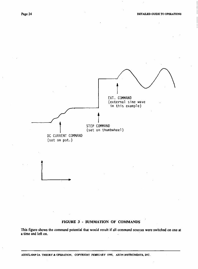
Complex command waveforms can be generated by appropriately mixing the Step Command, the DC Command and the Ext. Command. For example, die command waveform in Fig. 3 can be used to establish the current injected into MEI by setting the Destination switch to the MEI position and using the MEI DC Command and the Ext. MEI Command input.
AXOCLAMP-2A THEORY & OPERATION, COPYRIGHT FEBRIJARY 1990, AXON INSTRUMENTS, INC.
Page 24 DETAILED GUIDE TO OPERATIONS
EXT. COMMAND (external sine wave in this example)
STEP COMMAND (set on thumbwheel)
DC CURRENT COMMAND (set on pot.)
HGURE 3 - SUMMATION OF COMMANDS
This figure shows the command potential that would result if all command sources were switched on one at a time and left on.
AXOCLAMP-2A THEORY & OPERATION, COPYRIGHT FEBRUARY 1990, AXON INSTRUMENTS, INC.
DETAILED GUIDE TO OPERATIONS Page 25
CURRENT MEASUREMENT
The current injected down each microelectrode is independendy measured. The measurement is true. Thus if the electrode blocks the measured current falls to zero even though a current command may exist.
Two current ou^uts apply to MEl. Im is the membrane current while Ii Cont. is the instantaneous current in MEI. In continuous modes (Bridge, cSEVC and even TEVC) Im and Ii Cont. are identical. However, in discontinuous modes (i.e. DCC and dSEVC) Im and Ii Cont. are different. Ii Cont. switches firom zero to some finite value at the sample rate. This is because for 30% of each period MEl is used for passing current while for the remaining 70% of each period no current is passeid and the IR drop due to the previous current is allowed to passively decay (see DCC and cSEVC sections). On the other hand, Im is the true membrane current. It is recovered from the instantaneous electrode current by a circuit which samples the current pulses, retains the samples during the passive-decay period, then scales the samples to yield the average current for the whole period. The Im output is smoothed by the output filter (see the Output Filter section).
The current in ME2 is labelled I2.
The gain of the current measurement circuits depends on the headstage current gain (H). It is 10 - H mV/nA.
The whole current into the bath can be separately measured using a virtual-ground headstage. (See die Virtual Ground section.)
DCC MODE
Description
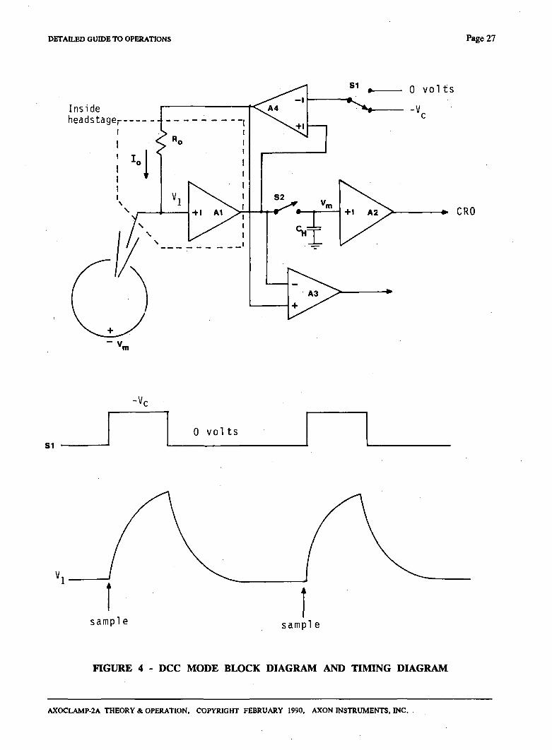
In Discontinuous Current Clamp (DCC) mode MEl is cyclically used to pass current. The voltage recorded at the tip of MEl is memorized by a sample-and-hold circuit inbetween each current-passing period after all transient voltages due to current passing have decayed. Thus the membrane potential can be recorded independendy of IR voltage drops across the electrode. The advantage of DCC mode compared with Bridge mode is that it is tolerant of small changes in microelectrode resistance. The disadvantage is that DCC mode is noisier than Bridge mode. During DCC mode ME2 can be used for continuous current passing.
The principles of operation are oudined in the block diagram and timing diagram of Fig. 4, and in the following discussion.
The voltage recorded by the microelectrode (Vi) is buffered by a unity-gain head stage (Al). To begin the discussion assume that Vt is exactly equal to the instantaneous membrane potential (Vm). Switch S2 briefly closes thereby enabling the voltage on die holding capacitor (CH) to charge up to the value of Vm-S2 opens again after the "sample" period and Vm is held by CH- A buffer amplifier (A2) interfaces CH to the recording apparatus. This switch, capacitor and buffer amplifier arrangement constitute an analog memory known as a sample-and-hold amplifier.
AXOCI-AMP-2A THEORY & OPERATION, COPYRIGHT FEBRUARY 1990, AXON INSTRUMENTS, INC.
Page 26 DETAILED GUIDE TO OPERATIONS
Immediately after the sample period, the current injection period begins when switch SI changes over ft-om the 0 volts position to the current-command voltage (Vc) position. This connects Vc to a differential amplifier (A4) arranged so that its output is Vi -I- Vc. The voltage appearing across Ro is exacdy equal to Vc diereby forcing the current (lo) into the microelectrode to be equal to Vc/Ro. Amplifiers A4 and Al and resistor Ro constitute a controlled-current source (CCS) which injects a current into the microelectrode direcdy proportional to the voltage at the input of the CCS irrespective of the resistance of the microelectrode or die voltage at its tip.
AXOCLAMP-2A THEORY & OPERATION, COPYRIGHT FEBRUARY 1990, AXON INSTRUMENTS, INC.
DETAILED GUIDE TO OPERATIONS Page 27
Inside headstage,-
• CRO
'm
S1
-Vr
0 v o l t s
sample sample
FIGURE 4 - DCC MODE BLOCK DIAGRAM AND TIMING DIAGRAM
AXOCLAMP-2A THEORY & OPERATION, COPYRIGHT FEBRUARY 1990, AXON INSTRUMENTS, INC.
Page 2 8 DETAILED GinOE TO OPERATIONS
During the current-injection period a square pulse of current proportional to Vc is injected into the electrode. Because of this current Vi rises. The rate of rise of Vi is limited by die parasitic effects of capacitance through the wall of the glass microelectrode to the solution, and capacitance at the input of the buffer amplifier. The final value of V] reached consists mosdy of the IR voltage drop across the microelectrode resistance. Only a tiny fraction of Vi consists of the membrane potential recorded at the tip.
After 30% of one cycle has elapsed, the voltage-recording period begins when SI changes over to the 0 volts position. Passive decay occurs because the input of the CCS is 0 volts and thus its output current is zero. Sufficient time must be allowed during the voltage-recording period for Vi to decay to widiin a millivolt or less of Vm. At the end of the passive decay period S2 is again briefly closed and a new sample of Vm is taken to begin a new cycle.
The actual voltage used for recording purposes is the sampled voltage. The sampled membrane potential is connected to the 10.Vm output. The Vi Cont. output is the instantaneous electrode voltage.
The instantaneous current into die microelectrode is monitored by a differentia] amplifier (A3). The output of A3 is taken to an averager (not shown) which samples, smoodis and scales the current pulses and connects the average value to die Im output.
During DCC mode die input to the CCS and the output of the MEl current monitor are automatically scaled so that they r^resent the true membrane current even though the instantaneous current flows for only 30% of the time.
The cycling (sampling) rate must be chosen so that there are ten or more cycles per membrane time constant. This enables the membrane capacitance to smooth the membrane voltage response to the current pulses.
Suggested Use
Turn the Anti-Alias Filter to the minimum value and switch to DCC mode. Set the Destination switch to MEl and set up a repetitive square current command. Observe Im and 10.Vm on the main oscilloscope. Observe the voltage at the Monitor output on a second oscilloscope (which need not be a high quality type) with the gain at 100 mV/div (= 10 mV/div input referred). Trigger this oscilloscope from the Sample Clock output on the rear panel.
Proceed to adjust the Capacitance Neutralization in one of two 1
A. For acceptable but not optimum Capacitance Neutralization, advance the Capacitance Neutralization control until the square step at the leading edge of the 10. Vm response is first eliminated.
B. For optimum Capacitance Neutralization, switch the Step Command generator to continuous. Advance the Capacitance Neutralization control until the Monitor waveform decays most rapidly to a horizontal baseline, but without any overshoot.
These techniques are illustrated in Fig. 5. The traces in Fig. 5A show that poorly adjusted Capacitance Neutralization during DCC mode is similar to poorly adjusted Bridge Balance during Bridge mode.
If the square step cannot be eliminated (without overshoot on the Monitor waveform), decrease the sample rate (fg).
Set die Output Bandwidth to 1/5 or less of fg.
Reduce the noise on the 10.Vm and Im traces either by advancing the Anti-Alias Filter or by increasing fg, adjusting the capacitance neutralization where necessary.
AXOCLAMP-2A THEORY & OPERATION, COPYRIGHT FEBRUARY 1990, AXON INSTRUMENTS, INC.
DETAILED GUIDE TO OPERATIONS Page 29
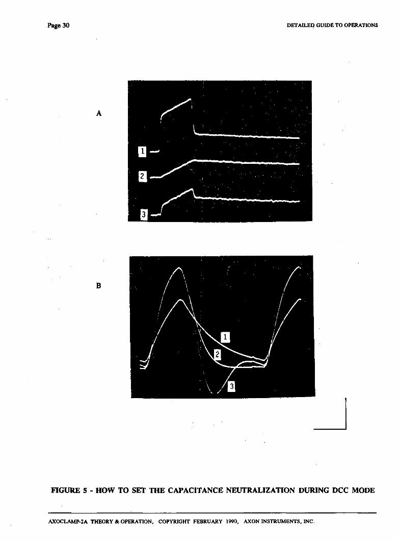
Figure 5
Illustration of Capacitance Neutralization adjustment during DCC. All traces were recorded with a model cell 10 M0//1 nF. Re was 10 MO. Cycling rate was 25 kHz.
A. 10.Vm ou^ut. Response to a 10 nA 1 ms current pulse. Vertical calibration: 20 mV referred to Vm-Horizontal calibration: 1 ms.
B. Vmon output during the 10 nA current pulse. Vertical calibration: 40 mV referred to Vm. Horizontal calibration: 10 /is.
There are diree pairs of corresponding traces.
Traces 1: Capacitance neutralization underutilized. There was a fast step in Vm at the start and finish of the current pulse because Vmon decayed too slowly to reach its final value.
Traces 2: Capacitance neutralization optimum. Vm shows the membrane response only. Vmon decay was fast widi no overshoot and easily reached the final value.
Traces 3: Capacitance neutralization overutilized. The fast steps in Vm reappeared, this time because of overshoot and ringing in Vmon- Note that unlike a Bridge circuit, the effect of two much compensation can put either a positive or a negative step on Vm (positive in this example) depending on which cycle ofthe ringing in Vmon is sampled.
AXOCLAMP-2A THEORY & OPERATION, COPYRIGHT FEBRUARY 1990, AXON INSTRUMENTS, INC.
Page 30 DETAILED GUIDE TO OPERATIONS
B
FIGURE 5 - HOW TO SET THE CAPACITANCE NEUTRALIZATION DURING DCC MODE
AXOCLAMP-2A THEORY & OPERATION, COPYRIGHT FEBRUARY 1990, AXON INSTRUMENTS, INC.
DETAILED GUIDE TO OPERATIONS Page 31
GROUNDING AND HUM
A perennial bane of electrophysiology is line-firequency pickup (noise), often referred to as hum. Hum can occur not only at the mains frequency but also at multiples of it.
The AX0CLAMP-2A has inherendy low hum levels (\ess than 20 /iV peak-to-peak). To take advantage of these low levels great care must be taken when integrating the AX0CLAMP-2A into a complete recording system. The following procedures should be followed.
(1) Only ground the preparation bath by directly connecting it to the yellow ground connector on the back of the MEl headstage (or to a virtual-ground headstage if used).
(2) Place the AXOCLAMP-2A in a position in the rack where transformers in adjacent equipment are unlikely to radiate into its electronics. The most sensitive part of the electronics is the right hand side looking ftom die front. A diick sheet of steel placed between the AX0CLAMP-2A and die radiating equipment can effectively reduce the induced hum.
(3) Initially make only one connection to the AX0CLAMP-2A. This should be to the oscilloscope ft-om the Vl or lO.Vm outputs. Ground die MEl headstage input dirough a 1 MO resistor to die yellow ground connector. After verifying that the hum levels are low, start increasing the complexity of the connections one lead at a time. Leads should not be draped near transformers which are inside other equipment. In desperate circumstances the continuity of the shield on an offending coaxial cable can be broken.
(4) Try grounding auxiliary equipment ftom a ground distribution buss. This buss should be connected to the AXOCLAMP-2A via the yellow 0.16 inch (4 mm) socket on the rear panel. This socket is connected to the AX0CLAMP-2A's isignal ground (i.e. the outer conductors of all the BNC connectors). The signal ground in the AX0CLAMP-2A is isolated ftom the chassis and power ground.
(5) If more than one headstage is used, all the headstage cables should run ftom the AXOCLAMP-2A to the preparation in a bundle. The bundle can be formed either by gendy twisting the cables together or by loosely tying them together.
(6) Experiment. While hum can be explained in theory (e.g. direct pickup, earth loops), in practice the ultimate theory is die end result. Following the rules above is the best start. The final hum level can often be kept to less than 100 /zV peak-to-peak referred to Vm. One technique that should not be used to reduce the hum is die delicate placement of cables so that a number of competing hum sources cancel out. Such a procedure is too prone, to accidental alteration.
DR. HARVEY J. KARTEN, M-D-UNIVERSITY OF CALIFORNIA, SAN DIEGO DEPARTMENT OF NEUROSCIENCES, 0608 9500 GILMAN DRIVE LA JOLLA, CA 92093-0608
AXOCLAMP-2A THEORY & OPERATION, COPYRIGHT FEBRUARY 1990, AXON INSTRUMENTS, INC.
Page 32 DETAILED GUIDE TO OPERATIONS
HEADSTAGES
The HS-2 unity gain headstage buffers the high impedance of the microelectrode, making the potential recorded by the microelectrode available to the rest of the circuitry. It also provides the means for injecting current into the microelectrode and for neutralizing the input capacitance.
The Meaning Of H
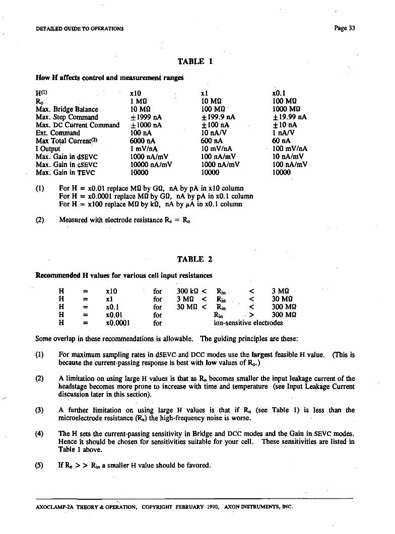
A precision resistor (Ro in Fig.4) inside the headstage sets the headstage current gain (H). Choosing the H depends on the cell to be clamped (see below). The particular value of H used affects the Bridge Balance range, the sensitivity to current commands, the sensitivity of the current monitors and the gain in SEVC mode. The effects are clearly marked on the front and rear panels, and since they always appear in multiples of 10 they are easy to calculate. For your convenience, Table 1 summarizes these effects. Note that voltage commands during voltage clamp are not affected.
Which Headstage To Use
The H value required depends on the typical input resistances (Rin) of your cells. The recommended values are in Table 2.
AXOCLAMP-2A THEORY & OPERATION, COPYRIGHT FEBRUARY 1990, AXON INSTRUMENTS, INC.
DETAILED GUIDE TO OPERATIONS Page 33
TABLE 1
How H affects control and measuremait ranges
HO) Ro Max. Bridge Balance Max. Step Command Max. DC Current Command Ext. Command Max Total Current ^) I OuQiut Max. Gain in dSEVC Max. Gain in cSEVC Max. Gain in TEVC
xlO IMQ 10 MO ±1999nA ±1000 nA 100 nA 6000 nA ImV/nA 1000 nA/mV 10000 nA/mV 10000
xl 10 MQ 100 MO ± 199.9 nA ±100nA 10 nA/V 600 nA 10 mV/nA 100 nA/mV 1000 nA/mV 10000
xO.l 100 MQ 1000 MO ± 19.99 nA ±10nA InA/V 60 nA lOOmV/nA 10 nA/mV lOOnA/mV 10000
(1) For H = xO.Ol replace MO by GO, nA by pA in xlO column For H = xO.OOOl replace MO by GO, nA by pA in xO. 1 colunm For H.= xlOO replace MO by kQ, tiA by /tA in xO. 1 colunm
(2) Measured with electrode resistance Re = Ro
H H H H H
xlO x l xO.l xO.Ol xO.OOOl
TABLE 2
ell input resistances
for 300 kO < Rin for 3 M 0 < Rin for 30 MO < Rin for Rin
< < < >
3 MO 30 MO 300 MQ 300 MO
for ion-sensitive electrodes
Some overlap in these recommendations is allowable. The guiding principles are these:
(1) For maximum sampling rates in dSEVC and DCC modes use the largest feasible H value. (This is because the current-passing response is best with low values of Ro.)
(2) A limitation on using large H values is that as Ro becomes smaller the input leakage current of the headstage becomes more prone to increase with time and temperature (see Input Leakage Current discussion later in this section).
(3) A ftirther limitation on using large H values is that if Ro (see Table 1) is less than the microelectrode resistance (Re) the high-frequency noise is worse.
(4) The H sets the current-passing sensitivity in Bridge and DCC modes and the Gain in SEVC modes. Hence it should be chosen for sensitivities suitable for your cell. These sensitivities are listed in Table 1 above.
(5) If Re > > Rin a smaller H value should be favored.
AXOCLAMP-2A THEORY & OPERATION, COPYRIGHT FEBRUARY 1990, AXON INSTRUMENTS, INC.
Page 34 DETAILED GUIDE TO OPERATIONS
Capacitance Neutralization Range
HS-2 Series headstages are available with L or M suffixes representing low and medium ranges respectively of Capacitance Neutralization (see Table 3). The increased Capacitance Neutralization range is a trade-off against microelectrode noise. The HS-2L has die lowest noise close to the theoretically predicted thermal noise of the electrode. The HS-2M has about 25% extra noise.
TABLE 3
HS-2L HS-2M Cap Neut Range:
in MEl Slot -1 to 4 pF -2 to 12 pF in ME2 Slot -1 to 11 pF -2 to 35 pF
Headstage Connectors
There are three teflon-insulated 2 mm (0.08 inch) sockets in the headstage (see diagram). These are standard-diameter sockets.
1. Microelectrode Input Connector The red socket is the microelectrode input. The connection between the microelectrode and this socket should be kept as short as possible. Some excellent methods are:
(i) Solder a silver/silver-chloride wire direcdy to one of the 2 mm plugs supplied. Use the -y' ^-j' -'' ' ^^^..?^fi-iffl' ' ' ^^^yr9i^^ which can be supported on a separate mounting.
(ii) For greater mechanical stability, use an HL-2 series microelectrode holder from Axon Instruments.
(iii) Plug a standard microelectrode holder (2 mm plug) direcdy into the input socket. The teflon input socket should allow enough clearance for most standard holders.
(iv) Use a BNC-type microelectrode holder. This requires an HLB-2 adaptor from Axon Instruments.
AXOCLAMP-2A THEORY & OPERATION, COPYRIGHT FEBRUARY 1990, AXON INSTRUMENTS, INC.
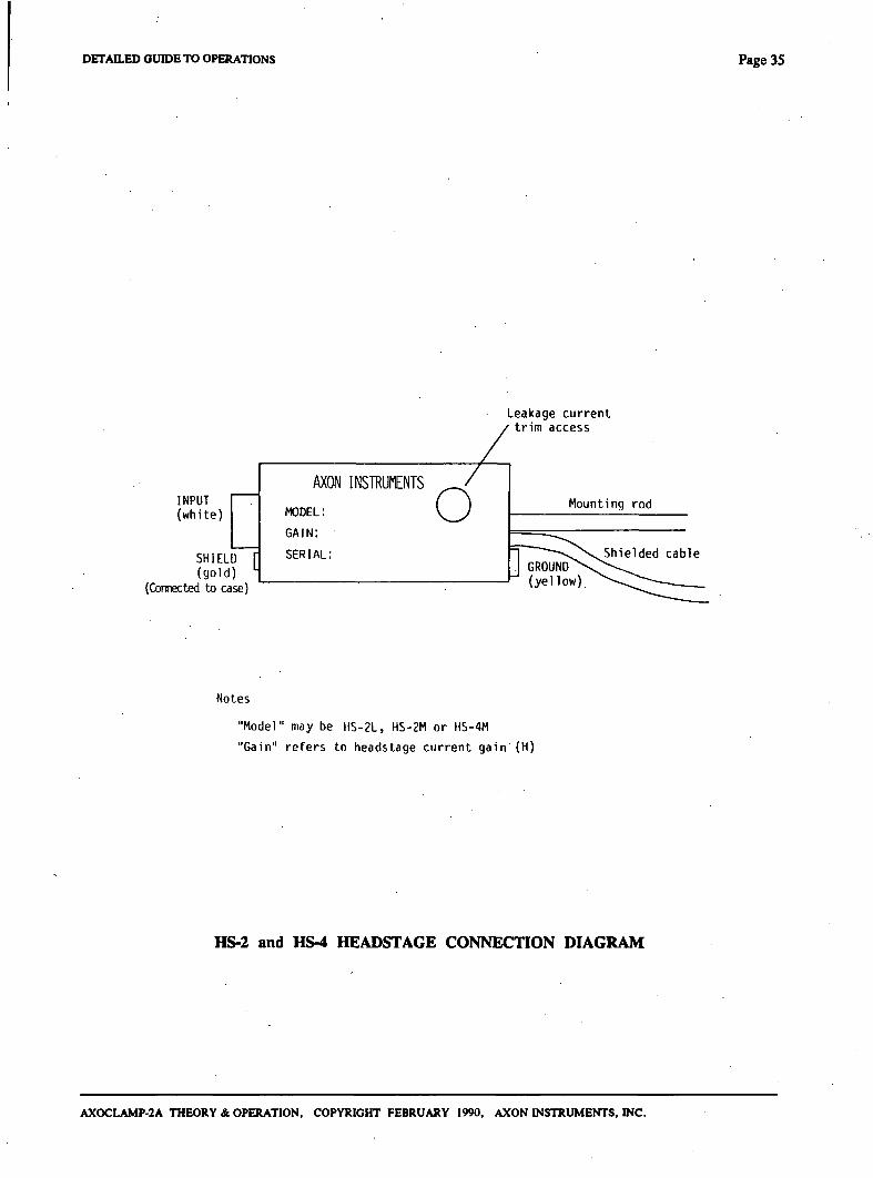
DETAILED GUIDE TO OPERATIONS Page 35
Leakage current trim access
INPUT (white)
SHIELD (gold)
{Connected to case)
AXON INSTRUMENTS
MODEL:
GAIN:
SERIAL:
o Mounting rod
Notes
"Model" may be HS-2L, HS-2M or HS-4M
"Gain" refers to headstage current gain (H)
HS-2 and HS-4 HEADSTAGE CONNECTION DIAGRAM
AXOCLAMP-2A THEORY & OPERATION, COPYRIGHT FEBRUARY 1990, AXON INSTRUMENTS, INC.
Page 36 DETAILED GUIDE TO OPERATIONS
2. Shield Drive Connector The Shield drive is connected to die gold-plated guard socket and to the case of die HS-2 xlL, xO.lL, xO.OlM and xO.OOOlM headstages. This drive is protected against continuous short circuits, however for best frequency response the case must not be grounded. In general, this necessitates using an insulated mounting for the headstage (such as die rod provided).
The shield connection is provided primarily for driving the shield of microelectrodes pr^ared for deep immersion (see notes in Microelectrodes for Fast Setding section). It may also be used for driving metal objects near the input, or even the hutch in which the preparation is housed. It can be used for driving the shield of a coaxial cable used to connect the microelecfrode to the input, although it is not recommended that the microelectrode be connected in this way. If not used, the shield socket is simply left unconnected.
There are two reasons why we do not recommend using shielded cable to connect the microelectrode to the headstage. (1) The leakage resistance of shielded cable can degrade the input resistance when used with ion-sensitive and other high-impedance elecfrodes. If shielded cable is used it should have teflon as the insulating material separating the shield and the inner conductor. . (2) Shielded cables add signiflcant input capacitance. The shield drive circuit mosdy removes the effect of this capacitance on electrode response speed. However, from a noise point of view the capacitance remains and causes an increase in high-frequency electrode noise.
To optimize the response speed of low and medium impedance electrodes (up to approx. 300 MO) when a driven shield is u s ^ , the shield of headstages with H = xO.l and larger is driven from the capacitance neutralization circuit. To optimize the headstage input resistance when a driven shield is used, die shield of headstages with H = xO.Ol and smaller is driven from the output of the unity gain buffer inside the headstage.
If a shielded cable is being used and unusual electrode responses are observed, try disconnecting the shield.
No shield drive is provided on the HS-2 xlMG, xlOMG and the HS-4 xlMG. On these headstages die case is grounded. This is because they are primarily used for current passing in a two-electrode voltage clamp (TEVC). In TEVC, it is essential to minimize the amount of coupling capacitance between the voltage-recording electrode and the current-passing electrode. This, coupling can be minimized most conveniendy if the case of the current-passing headstage is grounded.
3. Ground Output Connector The yellow ground socket of the MEl headstage is used for grounding the preparation. Using this connection as the preparation ground minimizes hum.
Tip Potentials - Detection
During the passage of current the tip potentials of many electrodes change. Changes in tip potential are indistinguishable from the membrane potential and can therefore represent a serious source of error. To prevent this error the following checks should be made.
(1) While the microelectrode is outside the cell, set the offset to zero. In bridge or DCC mode pass a constant current into die bath for about 10 seconds. The current magnitude should be die same as the maximum sustained current likely to be passed during the experiment. When the current is switched off the recorded potential should return to zero within a few milliseconds at most. Some electrodes either retum very slowly to zero potential, or not at all. These electrodes should be discarded.
AXOCLAMP-2A THEORY & OPERATION, COPYRIGHT FEBRUARY 1990, AXON INSTRUMENTS, INC.
DETAn.ED GUIDE TO OPERATIONS Page 37
(2) Once the experiment is in progress occasionally check the resistance of the microelectrode. Changes in tip potential are usually accompanied by changes in electrode resistance.
Note that the tip potential changes described in this section are h^pening widi a slower time course than the ones described in the Anti-Aliasing section. The causes of these slow changes in tip potential are unknown.
Tip Potentials - Prevention
Not much can be done to prevent tip potentials from changing but the following may be helpful.
(1) Sometimes the slow changes in tip potentials are worse when standard microelectrode holders with an embedded AgCI pellet are used instead of an Ag/AgCI wire. Some holders are all right while other ostensibly identical holders are not. Therefore holders should be tested and selected.
The variability of the tip potentials may in some way be related to pressure developed when the microelectrode is pressed into the holder. A narrow hole drilled into the side of the holder to relieve pressure might help.
(2) Using filling solutions with low pH, or adding small concentrations of polyvalent cations like Th^+, may reduce the size of the tip potential (Purves, 1981) and therefore the magnitude of any changes.
Interchangeability
Any unity-gain headstage in the HS-2 series can be used for MEl or ME2. The equipment will not be damaged if headstages are exchanged while the AXOCLAMP-2A is switched on.
Cleaning
To clean salt spills from die input connectors wipe with a damp cloth. Avoid spilling liquids on the headstage.
Input Leakage Current And How To Trim It To Zero
All DC-connected systems suffer from die problem of drift. With changes in temperature and the passage of time the DC transfer functions of all semiconductor devices can drift by many millivolts away from their initial values. The major worry in a microelecfrode system is that the cumulative effects of drift in various parts of the circuit may lead to the development of a DC offset across the resistor (Ro) used to set die H. As a result, an undesirable DC leakage current is injected into die microelecfrode.
Careful consideration to this problem has been applied diroughout the design of the AXOCLAMP-2A and die overall DC offset has been made as insensitive as possible to the drift in die integrated circuits. As well, special low-drift integrated circuits have been used in all critical positions. The magnitude of the DC leakage current increases with increases in H. This normally introduces no greater error in the DC offset voltage developed across the microelecfrode or the cell membrane because larger Hs are usually used with lower-resistance cells and microelecfrodes.
AXOCLAMP-2A THEORY & OPERATION, COPYRIGHT FEBRUARY 1990, AXON WSTRUMENTS, INC.
Page 38 DETAILED GUIDE TO OPERATIONS
Before leaving die factory, die DC offset voltage of each HS-2 headstage is trinuned so diat die input leakage current is no more than:
100 10 1 1 10
pA pA pA pA fA
for for for for for
H H H H H
= xlO = xl = xO.l = xO.Ol = xO.OOOl
Tliese input current levels are very low and cause negligible shifts in the cell membrane potential when the headstages are used with the recommended ranges of cell input resistances (see Table 2). (The shift in Vm is calculated from input current x Rin.)
If you ever suspect that the input current has grown to a level where Vm is significandy affected, it can be re-adjusted by the following procedure.
(1) Switch off all current commands and disconnect any external current commands.
(2) Remove the plastic cap from the access hole in the headstage cover.
(3) Ground the headstage input via a resistor equal to Ro - 10 (where Ro is given in Table 1). On an oscilloscope at 2 mV/div observe the lOVm output through die filter set to 100 Hz. Use the Offset control to center the trace on the screen.
(4) Now ground the headstage input via a resistor equal to Ro ' in Table 1. Observe the shift of the oscilloscope frace.
(5) Rq)etitively swap from grounding via Ro - 10 to grounding via R©. Adjust the ttim pot inside the headstage until there is no shift.
Note 1. For values of 1 GO or more it is important to clean the surface of the resistor thoroughly to remove leakage pathways.
Depending on the reason for a trim being necessary, the frim procedure may have to be repeated if die headstage is changed.
Warning
If an extemal source is connected to the Ext. MEl and ME2 Command input, any time the source is nonzero a proportional current will flow in the microelectrode. Many external sources do not put out a tme zero voltage when in the "off state, thus diere may be an unwanted electrode current due to the fact that an extemal source is connected. To avoid this, use an extemal source in which you can adjust the off-state voltage, or use an isolated extemal source.
DC Removal
One potential source of a small but variable input leakage current is due to DC current flow through the dielecfric of die capacitor (Co) used for capacitance neutralization. For example, die elecfrode potential might be 200 mV (diough the experimenter does not see diis potential because of die offset compensation). To compensate several pF of input capacitance die gain of the capacitance neutralization circuit might be 2. Thus 4<)0 mV would be fed back to Cn resulting in 200 mV across it. If the dielecfric resistance of Co were 10" 0 (the guaranteed minimum of high-quality capacitors) there would be 2 pA flowing through the capacitor.
AXOCLAMP-2A THEORY & OPERATION, COPYRIGHT FEBRUARY 1990, AXON INSTRUMENTS, INC.
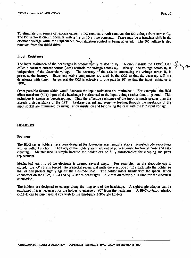
DETAILED GUIDE TO OPERATIONS Page 39
To eliminate this source of leakage current a DC removal circuit removes the DC voltage from across Cn. The DC removal circuit operates widi a 1 s or 10 s time constant. There may be a fransient shift in die elecfrode voltage while the Capacitance Neufralization confrol is being adjusted. The DC voltage is also removed from the shield drive.
Input Resistance
The input resistance of die headstages is predornkj^dy related to Ro. A circuit inside the AXOCLAMP V , 3j» • called a constant current source (CCS) controls the voltage across Ro. Ideally, the voltage across Ro is / a ^ independent of the elecfrode voltage. The accuracy of die CCS in controlling the voltage across Ro is preset at the factory. Extremely stable components are used in the CCS so that the accuracy will not deteriorate widi time. In general the CCS is effective to one part in 10^ so that the input resistance is lO^Ro.
Other possible factors which would decrease the input resistance are minimized. For example, the field effect fransistor (FET) input of the headstage is referenced to the input voltage rather than to ground. This technique is known as bootsfrapping. Thus the effective resistance of the input is much greater than die already high resistance of the FET. Leakage current and resistive loading through the insulation of the input socket are minimized by using Teflon insulation and by driving the case with the DC input voltage.
HOLDERS
Features
The HL-2 series holders have been designed for low-noise mechanically stable microelectrode recordings with or without suction. The body of the holders are made out of polycarbonate for lowest noise and easy cleaning. Maintenance is simple because the holder can be fully disassembled for cleaning and parts replacement.
Mechanical stability of the elecfrode is assured several ways. For example, as the elecfrode cap is closed, the 'O' ring is forced into a special recess and pulls the elecfrode fimdy back into the holder so diat its end presses tighdy against the electrode seat. The holder mates fimdy with the special teflon connectors on the HS-2, HS-4 and VG-2 series headstages. A 2 mm diameter pin is used for die elecfrical connection.
The holders are designed to emerge along the long axis of the headstage. A right-angle adapter can be purchased if it is necessary for the holder to emerge at 90° from die headstage. A BNC-to-Axon adaptor (HLB-2) can be purchased if you wish to use third-pary BNC-style holders.
AXOCLAMP-2A THEORY & OPERATION, COPYRIGHT FEBRUARY 1990, AXON INSTRUMENTS, INC.
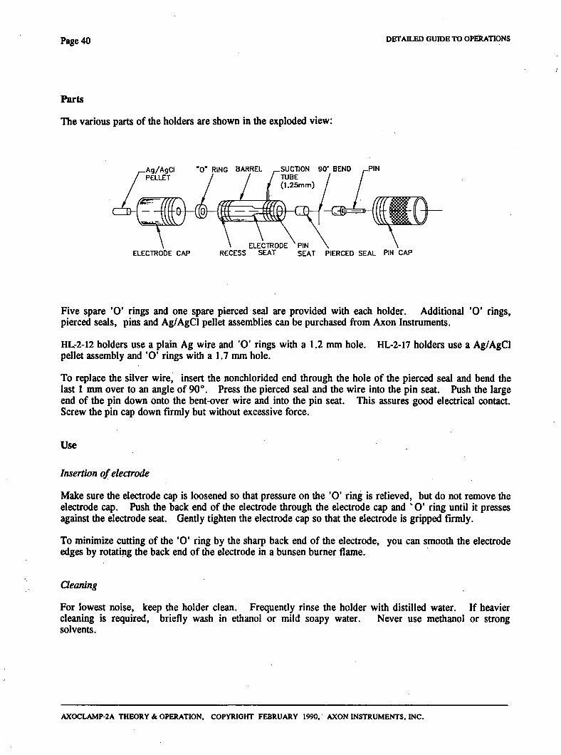
Page 4 0 DETAILED GUroE TO OPHIATIONS
Parts
The various parts of the holders are shown in the exploded view:
-Ag/AgCI ' 0 " RING BARREL SUCTION 90' BEND ^PIN PELLET / / / TUBE
(1.25mm)
- C ^ : ^
ELECTRODE PIN ELECTRODE CAP RECESS SEAT SEAT PIERCED SEAL PIN CAP
Five spare 'O' rings and one spare pierced seal are provided widi each holder. Additional 'O' rings, pierced seals, pins and Ag/AgCl pellet assemblies can be purchased from Axon Instmments.
HL-2-12 holders use a plain Ag wire and 'O' rings widi a 1.2 mm hole. HL-2-17 holders use a Ag/AgCl pellet assembly and 'O' rings with a 1.7 mm hole.
To replace the silver wire, insert the nonchlorided end through the hole of the pierced seal and bend the last 1 mm over to an angle of 90°. Press the pierced seal and die wire into the pin seat. Push die large end of the pin down onto the bent-over wire and into the pin seat. This assures good elecfrical contact. Screw the pin cap down firmly but without excessive force.
Use
Insertion of electrode
Make sure the electrode cap is loosened so diat pressure on the 'O' ring is relieved, but do not remove the elecfrode c ^ . Push die back end of die elecfrode through the electrode cap and ' O ' ring until it presses against the elecfrode seat. Gendy tighten die electrode cap so diat the electrode is gripped firmly.
To minimize cutting of the 'O' ring by the sharp back end of the electrode, you can smooth the electrode edges by rotating the back end of the electrode in a bunsen bumer flame.
Qeaning
For lowest noise, keep the holder clean. Frequendy rinse the holder with distilled water. If heavier cleaning is required, briefly wash in ethanol or mild soapy water. Never use methanol or strong solvents.
AXOCLAMP-2A THEORY & OPERATION, COPYRIGHT FEBRUARY 1990, AXON INSTRUMENTS, INC.
DETAILED GUIDE 1X3 OPERATIONS p a g e 41
Filling electrodes
Only the taper and a few millimeters of the shaft of the elecfrode should be filled with solution. The chlorided tip of the wire should be inserted into this solution. Avoid wetting the holder since this wUl increase the noise.
Silver Chloriding
The HL-2-17 holders are supplied with a Ag/AgCI pellet that should give you many months of DC-stable recordings. The silver wire is surrounded by a Sylgard-sealed teflon tube. This ensures that the elecfrode solution only contacts die Ag/AgCl pellet.
Ag/AgCI SYLGARD _ TEFLON PELLET / / TUBING
Ag WIRE
It is not practical to make a pellet small enough to fit inside the shaft of the narrow glass elecfrodes used in die and HL-2-12 holders, therefore these holders are supplied widi a piece of 0.25 mm silver wire. It is up to you to chloride the end of this wire as required. Chloriding procedures are contained in many elecfrophysiology texts (e.g. Purves, 1981). Typically the chlorided wire will need to be replaced every few weeks.
Heat smoothing the back end of the electrode extends the life of the chloride coating by minimizing the amount of scratch damage. Anodier way to protect die AgCI coating is to slip a perforated teflon tube over the chlorided region.
The chlorided region should be long enough so that die electrode solution does not come in contact widi the bare silver wire.
(Hass Dimensions
Use the HL-2-12 holders for glass from 1.0 to 1.2 mm outside diameter (OD). The optimal dimensions are 1.15 mm OD and > 0.5 mm ID.
Use the HL-2-17 holders for glass from 1.5 to 1.7 mm outside diameter (OD). The optimal dimensions are 1.65 mm OD and > 1.1 mm ID.
For other glass dimensions you can drill out the bore of the HL-2-12 holder.
AXOCLAMP-2A THEORY & OPERATION, COPYRIGHT FEBRUARY 1990, AXON INSTRUMENTS, INC.
Page 42 DETAILED GuroETX) OPERATIONS
I IONOPHORESIS
A
When ME2 is not used for intracellular penefrations it can be used for ionophoresis. To set the retaining and pulse currents:
(1) Set the desired retaining current on die ME2 DC Current Command control.
(2) Switch the Destination switch to ME2. Set the Step Command equal to die desired pulse cunent minus the retaining cunent.
or Connect a pulse generator to the Ext. ME2 Command input to set the desired pulse current nunus the retaining current.
e.g. For retaining current = -5 nA, ejection current = 40 nA. Set ME2 DC Current Conunand = -5 nA, Step Command (or Ext. ME2 Conunand) = 45 nA.
Use a headstage widi the appropriate H. xl is generally useful.
LINK-UP
When the AXOCLAMP-2A is used in dSEVC and DCC modes the voltage across the microelecfrode rapidly switches up and down. To an extent which depends on proximity, a second microelecfrode used in the same pr^aration will pick up some switching noise.
If die second elecfrode is used in a continuous mode the picked up noise can usually be removed by a lowpass filter.
If the second elecfrode is also used in a discontinuous mode (e.g. when two interconnected cells in the same preparation are placed under dSEVC) the pick-up from one to the other can become a problem. The two switching signals mix and a beat frequency signal appears at the difference frequency. When both elecfrodes are switched at similar frequencies the beat frequency signal appears at a low frequency which cannot be filtered out. Worse, in an effort to clamp out the beat signal the clamping circuit passes beat-frequency currents into the cell.
There are two ways to avoid this problem.
(1) Place an extensive grounded shield between the two electrodes. This method has disadvantages. The shield may be physically difficult to arrange, and it may introduce sufflcient capacitance at the headstage inputs to worsen the electrode performances.
(2) Use the Clock Link-Up facility provided widi each AXOCLAMP-2A to synchronize dieir sampling clocks. A 15-pin connector on the rear panel enables the sampling clock circuits of two AXOCLAMP-2AS to be linked by a cable. One AX0CLAMP-2A becomes the Master and die odier the Slave (which is which is determined by die orientation of the cable).
After Link-up, whenever bodi AXOCLAMP-ZAs are in DCC or dSEVC modes, die Slave's sampling clock is overridden by die Master's. In all odier combinations of operating modes die two AXOCLAMP-2AS remain fiilly independent. For example, if the Slave is in DCC or dSEVC modes but the Master is in neidier, the Slave's sampling clock is re-enabled.
AXOCLAMP-2A THEORY & OPERATION, COPYRIGHT FEBRUARY 1990, AXON INSTRUMENTS, INC.
•t
DETAILED GUIDE TO OPERATIONS Page 4 3
By forcing both AXOCLAMP-2AS to sample synchronously the beat frequency problem is eliminated. At the instant that both AX0CLAMP-2AS sample dieir elecfrode voltages there will be no pick-up from one elecfrode to the odier because the voltages across both elecfrodes must have decayed to near zero in order for the clamps to operate.
Clock Link-Up only affects the sampling clocks. All odier functions of the two AXOCLAMP-2AS remain fully indqiendent.
MICROELECTRODES FOR FAST SETTUNG
The key to discontinuous voltage and current clamping with a single nucroelecfrode is the character of the microelectrode itself. The microelectrode voltage must settle rapidly after a current pulse, and the microelecfrode must be able to pass current without large changes in resistance.
Microelectrode Capacitance
To get fast setding it is essential to minimize the transmuraL-capacitance^(Ct) from the inside of the microelecfrode to the extemal solution. Ct is usually 1-2 pF per mm of immersion. Two applications requiring different appiroaches are discussed here.
Target Cell Near Surface Of Solution.
In an isolated pr^aration, Ct can be reduced, by lowering.the.surfacjejcrf_the_so.lution,aSi.,faL3s.pp.ssibJe^(see note below). Precautions must be taken to prevent surface tension effects from drawing a thin layer of solution up the outer wall of die microelectrode. If this film of saline is allowed to develop, Ct will be much worse that otherwise. Because die film of saline has axial resistance the contribution to Ct will be very nonlinear, and the voltage decay after a current pulse will eidier be biphasic (as in Fig. 1), or if it is monophasic it will not be very fast even when capacitance neufralization is used. To prevent the saline film ft'om developing, the electrode should be coated with a hydrophobic material. This can be-donejust^ before use by dipping the filled microejecfrodeinto a fluid such as silicpnejoil^^orjmMraTod. Another method is to coat die elecfrode with Sylgafd'^Hamill et al., 1981). • • ~ - . .L ..._
Sylgard or Q-dope (airplane glue) can also be used to build up the wall diickness of the elecfrode thereby reducing Ct. The selected material should be painted onto the elecfrode to widiin 100 /im ofthe tip.
Note: For a long slender microelectrode we regard 2(X) fim or less as a low solution level. 500 /im is tolerable. 1 mm or more is regarded as deep. For a microelecfrode which tapers steeply (i.e. a stubby microelectrode) deeper solutions can be used with less loss of performance. When working with very low solution levels there is a risk of evaporation exposing the cells to the air unless a continuous flow of solution is provided across or through the preparation. If evaporation is a problem one way to overcome it is to float a layer of mineral oil on the surface of die solution. If used, this layer of oil will have the additional advantage of automatically coating the electrode as it is lowered into the solution.
AXOCLAMP-2A THEORY &. OPERATION, COPYRIGHT FEBRUARY 1990, AXON INSTRUMENTS, INC.
I
'V,6
Page 4 4 DETAILED GIHDE TO OPERATIONS
Target Cell Deep In Solution.
In some pr^arations, e.g., in vivo CNS, the target cell is several millimeters below the surface of the solution. In this case the more difflcult procedure of guarding the electrodes may have to be used. This involves coating the outside of the microelecfrode with a metal layer and connecting this layer to the case socket of the unity-gain headstage. Depending upon H the case socket is either connected to the capacitance neutralization circuit or to the unity-gain output. The guarding procedure does not reduce Ct. Instead, it reduces the effect of Ct by confrolling the voltage across it. The metal guard layer must be insulated from the preparation solution. For different i^proaches to this method see Schwartz & House (1970), Suzuki, Rohli?ek & Frbmter (1978), Sachs & McGarrigle (1980) and Finkel & Redman (1983).
Shielding the elecfrode introduces high-frequency noise therefore it should only be done when absolutely necessary. The amount of added noise is proportional to the amount of shield c^acitance, so only the minimum necessary length of microelectrode should be shielded.
Because of the disfributed nature of the axial resistance of the microelectrode, of the axial resistance of the metal layer, and of Ct, the shielding technique is not perfect. In practice, the effect of these nonidealities is to cause the step response of the microelectrode to overshoot even when the Capacitance Neutralization gain is unity. For this reason, the Capacitance Neutralization circuit has a minimum less than unity.
Microelectrode Resistance
Another important aspect of the microelectrode is die tip resistance (Re). This should be as low as possible consistent with good impalements of the cell. There are two advantages associated with low values of Re:
Settling Time
The decay time constant for the microelectrode voltage after a current pulse depends sfrongly on Re. Hence, lower Re values produce faster settling times. As well, high Re values are sometimes associate with a slow final decay even after Ct has been eliminated.
Stability
Re of most microelecfrodes changes with time and with current passing. Re is affected not only by the magnitude of the current but also by its polarity. In general, microelectrodes of lower resistance are more stable during current passing than microelectrodes of higher resistance.
Filling Solutions
The best filling solution to use depends on the preparation under investigation and the experience of the investigator. Although KCI gives one of the lowest tip resistances for a given tip diameter it is not necessarily the fastest to setde after a current pulse. K-cjtrate is sometiniesJiastec.
It is important to be aware that during current-passing large amounts of ions from inside the microelectrode can be ionophoresed into the cell. For example, if current is passed by the flow of ion species A from the microelectrode into the cell, then after 50 seconds of current at 1 nA (or 1 second of current at 50 nA) the change in concentration of A inside a cell 100 /zm in diameter is 1 mM. If A is an impermeant ion,
-the cell may swell due to the inflow of water to balance the osmotic pressure.
Recommended Reading
A small book by Purves (1981) serves as an excellent general reference for microelectrode techniques.
AXOCLAMP-2A THEORY & OPERATION, COPYRIGHT FEBRUARY 1990, AXON INSTRUMEI4TS, INC.
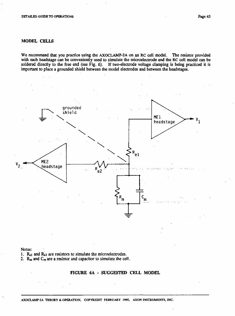
DETAILED GUIDE TO OPERATIONS Page 45
MODEL CELLS
We recommend diat you practice using the AXOCLAMP-2A on an RC cell model. The resistor provided with each headstage can be conveniendy used to simulate die microelecfrode and the RC cell model can be soldered direcdy to the free end (see Fig. 6). If two-elecfrode voltage clamping is being practiced it is important to place a grounded shield between the model elecfrodes and between the headstages.
Notes: 1. Rei and Re2 are resistors to simulate the microelectrodes. 2. Rm and Cm are a resistor and capacitor to simulate die cell.
FIGURE 6A - SUGGESTED CELL MODEL
AXOCLAMP-2A THEORY & OPERATION, COPYRIGHT FEBRUARY 1990, AXON INSTRUMENTS, INC.
Page 46 DETAILED GUIDE TO OPERATIONS
The CLAMP-1 Model Cell
If you do not need to model your cell exacdy, the CLAMP-1 Model Cell shipped with your AX0CLAMP-2A is a convenient model to work with. The cell and elecfrode components simulate a small-to-medium sized cell having an input resistance of 50 MQ, a membrane time constant of 25 ms and electrode resistances of 50 MO. See Figure 6B. The case of the model cell is connected to ground. Shielding between the two elecfrode resistors is effected by the body ofthe switch.
Install the model cell by plugging it into one or both of your headstages. Connect the gold-plated ground jack to the yellow jack on the back of the MEl headstage using the cable provided. Do not make any connection to the gold-plated jack on the front of the HS-2 headstage - this is connected to die headstage case which is driven to the electrode potential.
When the switch is in the BATH position, both elecfrode resistors are connected to ground. This is a convenient position for practicmg^idge balancing techniques and offset adjustment. -^ p $D
When the switch is in the CELL position, both electrode resistors are effectively intracellular. In Bridge or DCC mode you should see exponential voltage responses to steps of current. In dSEVC mode you should be able to clamp the cell at gains of up to 0.8 nA/mV using an HS-2 xO.l headstage, at sampling rates up to 8 kHz. In TEVC mode, use one of the following electrode combinations: 1) two xO.l headstages, two xl headstages, or a xl headstage for ME2 and a xO.l headstage for MEl. The elecfrode resistances in this model cell are too large for you to practice cSEVC.
AX0CLAMP-2A THEORY & OPERATION, COPYRIGHT FEBRUARY 1990, AXON INSTRUMENTS, INC.
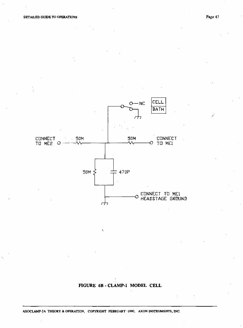
DETAILED GUIDE TO OPERATIONS Page 47
.CONNECT TD ME2 O
50M — W -
50M S
r t i
470P
CELL BATH
m
50M CONNECT - W O TD MEl
_ CONNECT TD MEl " HEADSTAGE GROUND
FIGURE 6B-CLAMP-I MODEL CELL
AXOCLAMP-2A THEORY & OPERATION, COPYRIGHT FEBRUARY 1990, AXON INSTRUMENTS, INC.
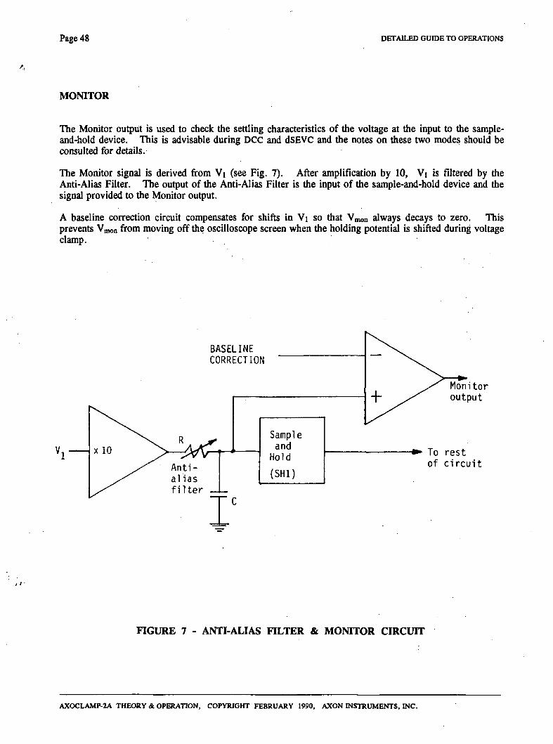
Page 48 DETAILED GUIDE TO OPERATIONS
MONITOR
The Monitor ou^ut is used to check the setding characteristics of the voltage at the input to the sample-and-hold device. This is advisable during DCC and dSEVC and the notes on these two modes should be consulted for details.
The Monitor signal is derived from Vi (see Fig. 7). After amplification by 10, Vj is filtered by die Anti-Alias Filter. The output of the Anti-Alias Filter is the input of the sample-and-hold device and the signal provided to the Monitor output.
A baseline correction circuit compensates for shifts in W\ so that Vmon always decays to zero. This prevents Vmon from moving off the oscilloscope screen when the holding potential is shifted during voltage clamp.
BASELINE CORRECTION
Monitor output
To rest of circuit
nGURE 7 - ANTI-ALIAS FILTER & MONITOR CIRCUIT
AXOCLAMP-2A THEORY & OPERATION, COPYRIGHT FEBRUARY 1990, AXON INSTRUMENTS, INC.
DETAILED GUIDE TO OPERATIONS Page 49.
NOISE IN DCC AND dSEVC MODES
The noise inherent in discontinuous microelecfrode clamps (discontinuous current clamp or discontinuous single-elecfrode voltage clamp) is four or more times worse than the noise in continuous microelecfrode clamps (bridge current clamp or two-elecfrode voltage clamp) when the discontinuous microelecfrode clamps are adjusted for the same dynamic response and accuracy as the continuous microelecfrode clamps.
There are two major reasons for this inherent deterioration in noise performance.
The first is to do with c^acitance neufralization. A fundamental property of all capacitance neutralization circuits is that they introduce noise in excess of what is contributed by the thermal noise of die recording microelecfrode and the input noise of the buffer amplifier. The excess noise becomes progressively larger as the microelecfrode time constant is reduced. In discontinuous systems the microelectrode time constant must be reduced more than in continuous systems so that after a current pulse the microelecfrode voltage will decay to Vm within the time allotted for passive recording. The excess noise due to optimizing the capacitance neutralization can vary from a factor of about two in a system where primary efforts have been taken to keep the input capacitance low, to much larger factors in systems where large amounts of c^acitance-to-earth and capacitance-to-shield are tolerated.
The second major reason for die deterioration in noise performance of discontinuous microelecfrode clamps has to do with the sampling process. As discussed in the section on the Anti-Alias Filter, sampling processes alias the noise in die input signal spectmm into a larger-magnitude spectmm confined to a bandwidth equal to half of the sampling rate (fg). The normal procedure used in digitizing systems to avoid aliasing is to reduce the bandwidth of the input signal to fs/2 or below. This is not possible in discontinuous microelecfrode clamping because reducing the bandwidth of the microelectrode increases the time constant and therefore prevents adequate settling. The amount of aliased noise depends in part on the current duty cycle used in the discontinuous clamp. The 30% duty cycle used in the AXOCLAMP-2A has been chosen to give a good compromise between aliased noise and dynamic performance (Finkel & Redman, 1984b). With this duty cycle the increase in noise due to aliasing is a factor of about two.
The two confributions to noise discussed above lead to a factor of four or more deterioration in noise. To keep the deterioration as small as this the experimenter should aim to do the following.
(1) Keep die real value of Cin as small as possible so diat only minimal capacitance neufralization must be used. (Avoid using coaxial cable to connect the microelectrode to the headstage.)
(2) Either increase die Anti-Alias Filter setting at a given cycle rate, or increase the cycle rate at a given setting of the Anti-Alias Filter, so that the amount of aliased noise is minimized.
Finally, the amount of noise recorded can be reduced to some extent by using as much output filtering as possible. However, the output filtering should neyer be increased to the extent that dynamic information (e.g. rise time) is lost. Usually, output filtering at fs/10 is a good compromise. The best way of reducing noise in the records is by averaging repetitive signals. This well-known procedure reduces the noise by the square root of the number of averages without affecting the time course of the signal.
Notwithstanding the comparatively poor noise performance of discontinuous single-electrode voltage clamps compared with two-electrode voltage clamps, the single-electrode technique is extremely rewarding because it allows voltage-clamps to be performed in preparations where two-electrode voltage clamping is just not feasible. As well, the signal-to-noise ratio in many preparations during discontinuous single-electrode voltage clamp is, despite the above considerations, adequate for data to be analyzed without averaging.
AXOCLAMP-2A THEORY & OPERATION, COPYRIGHT FEBRUARY 1990, AXON INSTRUMENTS, INC.
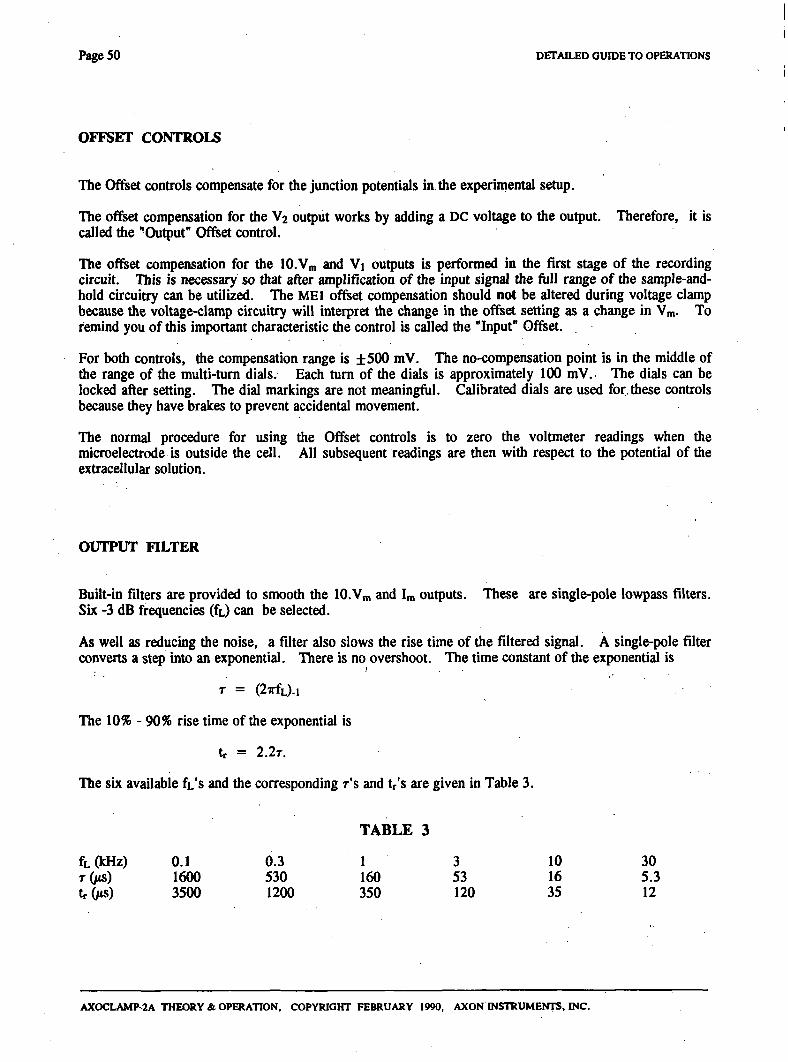
Page 5 0 DETAILED GUIDE TO OPERATIONS
OFFSET CONTROLS
The Offset confrols compensate for die junction potentials in the experimental setup.
The offset compensation for the V2 output works by adding a DC voltage to the output. Therefore, it is called die •Output" Offset control.
The offset compensation for the lO.Vm and Vj outputs is performed in the first stage of die recording circuit. This is necessary so that after amplification of the input signal the full range of the sample-and-hold circuitry can be utilized. The MEl offset compensation should not be altered during voltage clamp because the voltage-clamp circuitry will interpret the change in the offset setting as a change in Vm. To remind you of this important characteristic the control is called the "Input" Offset.
For both confrols, the compensation range is ±500 mV. The no-compensation point is in the middle of the range of the multi-tum dials. Each tum of the dials is approximately 100 mV. The dials can be locked after setting. The dial markings are not meaningfiil. Calibrated dials are used for these controls because they have brakes to prevent accidental movement.
The normal procedure for using the Ofiset controls is to zero the voltmeter readings when the microelecfrode is outside the cell. All subsequent readings are dien with respect to the potential of the exfracellular solution.
OUTPUT FILTER
Built-in filters are provided to smooth the lO.Vm and Im outputs. These are single-pole lowpass filters. Six -3 dB frequencies (fO can be selected.
As well as reducing the noise, a filter also slows the rise time of the filtered signal. A single-pole filter converts a s t^ into an exponential. There is no overshoot. The time constant of the exponenti<d is
T = (2irfL)-i
The 10% - 90% rise time of the exponential is
tr = 2.2T.
The six available ft's and the corresponding r's and tr's are given in Table 3.
TABLE 3
0.3 1 3 10 30 530 160 53 16 5.3 1200 350 120 35 12
fL(kHz) TQIS)
tr(MS)
0.1 1600 3500
AXOCLAMP-2A THEORY & OPERATION, COPYRIGHT FEBRUARY 1990, AXON INSTRUMENTS, INC.
DETAILED GUIDE TO OPERATIONS Page 51
High-Order Lowpass Filters For Low-Noise Recordings
The "order" of a filter refers to die number of poles (RC sections). For example, a third-order fdter has three poles. Each pole attenuates the high-frequency noise at 20 db/decade.
During TEVC the current noise increases at -1-20 db/decade above a frequency determined by the membrane time constant (Finkel & Gage, 1984). To adequately limit this noise the filter used for data display and storage should be at least 2™* order and preferably 3"* or 4* order.
Rise Time Of High-Order Filters
As a mle of diumb it can be noted that for lowpass multiple-pole filters having less than 10% overshoot, the 10-90% rise time is within a few percent of t in a single-pole filter having the same -3 dB frequency.
However, the frequency specified for many multiple-pole lowpass filters is the -3 dB frequency of the component lower-order filters instead of being the -3 dB frequency of the complete filter. Before using these filters it is advisable to check the 10-90% rise time of a step signal applied to the input.
Note On Ultimate Rise Time
When a signal with 10-90% rise time ti is passed through a filter widi 10-90% rise time t2 the rise time of the output signal is approximately
tr = V (tl2 -»• t22)
OUTPUT IMPEDANCE AND PROTECTION
All outputs are protected by 560 0 output resistors.
All outputs can withstand a continuous short circuit to ground or any voltage in the ±15 V range. However, in keeping with normal practice, such short circuits should be avoided.
PANEL METERS
Three digital panel meters (DPMs) are provided to continuously display the DC level of some of the important outputs. These displays are.
V^CmV)
This DPM indicates the membrane potential in all modes. It is derived from the 10.Vm output. The maximum displayed value is approximately ±600 mV, which is the value which will typically be seen when the MEl headstage input is open circuit.
AXOCLAMP-2A THEORY & OPERATION, COPYRIGHT FEBRUARY 1990, AXON INSTRUMENTS, INC.
Page 52 DETAILED GUIDE TO OPERATIONS
V2(mV)
This DPM indicates V2 in all modes. The maximum displayed value is ± 1999 mV. Out-of-range signals, are indicated by a partially blanked display, and + or - to indicate polarity.
KnA)
This DPM can display one of die following currents: Im, I2 or IVIRT. The current to be displayed is chosen using the I-Display Select switch.
Three small switches are used to change the decimal point location so that the display can be read direcdy in nA for the headstage being used. The HCGi switch is active when the I-Display Select switch is in the Im position; the HCGi switch is active when I2 is selected; the VG switch is active when IVIRT is selected. To use, tum the switch to the gain of your headstage. . ^ , , •
— — ^ f ^ t i - o . \ y
PHASE
A voltage-clamp is a negative-feedback circuit and as such it requires a 90° phase shift within the circuit. Ideally this phase shift is supplied by the capacitance of the membrane. In practice, membranes introduce significandy less than 90° phase shift (see discussion by Finkel & Gage, 1984).
The frequency response of the voltage-clamp circuit can be modified by die Phase controls. The voltage-clamp circuit can diereby be adjusted to compensate for the nonideal phase response of real membranes.
The controls are in two parts; a potentiometer to shift from lead to lag, and a 4-position switch to set the time constant.
Phase lead boosts the high-frequency gain of the voltage-clamp circuit. In some preparations this can be used to sharpen the step response and improve the voltage clamping of fast conductance changes. On the debit side, use of phase lead increases the noise and can also cause high-frequency oscillations. To reduce the risk of oscillations the phase-control circuit is arranged to always introduce some phase lag with the phase lead. The added phase lag restricts die maximum increase in the high-frequency gain to a factor of 2, achieved when the potentiometer control is tumed to the extreme lead position.
Phase lag cuts the high-frequency gain of the voltage-clamp circuit. This can be used to reduce the noise but at die same time it slows die response and introduces ringing. In die extreme lag position the phase-control circuit introduces pure lag.
The action of the Phase Shift potentiometer can be summarized as follows. In the extreme lead position a combination of phase lead and lag is introduced such that the high-frequency gain is doubled. The amount of phase lead is gradually reduced by counterclockwise rotation of the potentiometer and falls to zero at the extreme lag position. At the same time the amount of phase lag cutting the high-frequency gain is increased by counterclockwise rotation of the potentiometer. At the center position of the potentiometer the net change to the frequency characteristics ofthe voltage-clamp circuit is nil.
The Time Constant switch changes the maximum lag and lead values as listed in the Specifications. In some pr^arations no phase lag or lead is required. If this is so, the Time Constant switch should be switched to the Off position.
With an RC cell model the best voltage-clamp will be achieved when no Phase shift is used.
AXOCLAMP-2A THEORY & OPERATION, COPYRIGHT FEBRUARY 1990, AXON INSTRUMENTS, INC.
DETAILED GUIDE TO OPERATIONS Page 5 3
Use .
The Phase confrols can be used during voltage clamp to compensate for die frequency characteristics of membranes which are not well modeled by a parallel resistance and c^acitance. Both the membrane voltage and current stq) responses should be improved by using the Phase controls. If only the membrane voltage step response is improved it is likely that there is a resistance (Rg) in series with the membrane. See the Series Resistance Section for a discussion of this problem.
In some cases using some phase lag wUl reduce die current noise during voltage clamp. See the Sections on each type of voltage clamp for more details.
POWER-SUPPLY GLITCHES
The AXOCLAMP-2A has been designed to minimize the effects of power supply transients (glitches). This is achieved by:
1) taking the incoming power through a radio frequency interference (RFI) filter and
2) capacitively isolating the transformer primaries and secondaries.
Nevertheless, some power-supply glitches do get through. These can cause fransients to ^pear on the voltage and current outputs which may cormpt high-sensitivity recordings (for example, during fluctuation analysis).
The only completely effective way to gain immunity from mains glitches is to eliminate them at the source. Most glitches are due to the switching on and off pf odier equipment and lights on the same power-supply circuit. Precautions to be taken include:
(1) Avoid switching equipment and lights on or off while recordings are being made.
(2) Water baths, heaters, coolers etc. should operate from zero-crossing relays.
(3) RFI filters should be installed in glitch-producing equipment.
In most circumstances occasional transients on the outputs are inconsequential aiid therefore no precautions have to be taken.
AXOCLAMP-2A THEORY & OPERATION, COPYRIGHT FEBRUARY 1990, AXON INSTRUMENTS, INC.
Page 54 DETAILED GUroE TO OPERATIONS
POV^^R SUPPLY VOLTAGE SELECTION & FUSE CHANGING
Supply Voltage
The AXOCLAMP-2A can work from all international supply voltages. The two input ranges are:
(1) 115V: For 100 Vac to 125 Vac operation.
(2) 230 V : For 200 Vac to 250 Vac operation.
To change the supply voltage setting:
(1) Disconnect the power cord
(2) Remove the top cover
(3) Locate the slide switch labeled "S2" at the back of the power supply board. The power supply board is the small horizontal board in the left side of the instmment.
(4) For 115 V operation slide S2 to die left towards die label " 115". For 230 V operation slide S2 to die right towards die label "230".
(5) Replace the top cover.
(6) Re-connect the power cord.
(7) Mark the new operating voltage on the identification plate on the rear of the instmment.
Changing The Fuse
The AXOCLAMP-2A uses a 0.5 A 250 V slow acting 5 x 20 mm fuse on bodi voltage ranges. Before changing the fiise investigate the reason for its failure.
To change the fiise:
(1) Disconnect the power cord.
(2) Use a screwdriver or something similar to lever out the fiise holder.
(3) Discard the fiise from the active slot, i.e. the slot which places the fuse closest to the inside of die instmment.
(4) Shift the spare fiise from the spare slot (i.e. the slot which places the fuse towards the outside of the instmment) to the active slot.
(5) Re-connect the power cord.
AXOCLAMP-2A THEORY & OPERATION, COPYRIGHT FEBRUARY 1990, AXON INSTRUMENTS, INC.
DETAILED GUHJE TO OPERATIONS Page 55
REMOTE
Some of the front-panel functions can be activated via the Remote connector at the rear of the Clamp. These are Mode selection. Buzz, and Clear. Possible uses of this facdity include using a computer to select the ModK, and using hand-operated or foot-operated switches for Buzz and Clear so that these hinctibns can used by the experimenter without moving from the nucroscope.
The selected functions are activated by HIGH logic levels applied to the ^propriate pin. New Modes are selected and kept after a HIGH level of 1 /is or more in duration. Buzz and Clear are activated for the duration of the HIGH level. Using the Remote facility does not disable the front-panel switches.
The pin connections for the Remote connector are as follows:
1. 2. 3. 4. 5. 6. 7. 8. 9.
10. 11. 12. 13. 14. 15.
DIGITAL Ground -1-5 V output BRIDGE mode DCC mode SEVC mode TEVC mode CLEAR MEl "-I-" CLEAR MEl "-" Not used Not used Not used CLEAR ME2"-!-" CLEAR ME2 "-" BUZZ ME2 BUZZ MEl
To use the Remote controls, the extemal control signals can be wired to a 15-pin D-type connector which can then be plugged into the Remote connector on the rear panel.
-1-5 V is provided for wiring up any remote switches you may use. Do not short circuit this supply. The Mode-Select inputs (pins 3H5) have 50 kO input resistances; the other inputs (pins 7, 8, 12-15) have 7 kO input resistances.
The FS-3 footswitches provided with the AX0CLAMP-2A consist of a pair of normally open switches for activating Buzz of each elecfrode. If footswitches are not convenient you can easily connect your preferred switches by following the wiring diagram below.
For remote operation of microelectrode 1 Buzz and microelectrode 2 Buzz.
AXOCLAMP-2A THEORY & OPERATION, COPYRIGHT FEBRUARY 1990, AXON INSTRIftlENTS, INC.
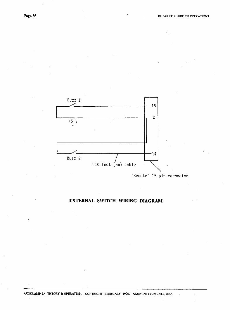
Page 56 DETAILED GUIDE TO OPERATIONS
Buzz 1
15
+5 V
Buzz 2 /
' 10 foot (3m) cable
•14
"Remote" 15-pin connector
EXTERNAL SWITCH WIRING DIAGRAM
AXOCLAMP-2A THEORY & OPERATION, COPYRIGHT FEBRUARY 1990, AXON INSTRUMENTS, INC.
DETAILED GWDE TO OPERATIONS Page 57
RMP BALANCE
The two indicator lights for monitoring resting membrane potential (RMP) are used in two ways.
Before switching into a voltage-clamp mode the Holding Position potentiometer is adjusted until the two lamps are equally dim (nulled). This ensures that when a voltage-clamp mode is selected the membrane potential will be held within a few millivolts of RMP. When adjusting the Holding Position control before voltage clamping the sensitivity of the null point is affected by the Gain.
During voltage clamp the RMP Balance lights provide a quick indication of when the cell is being held at its resting level. That is, the RMP Balance lights are nulled at diis point.
SERIES RESISTANCE
Origin
A resistance (Rg) in series with the membrane can arise a number of different ways. In cSEVC, Rg would mainly be due to the resistance of die suction electrode. In dSEVC, Rg would be due to a slow microelecfrode response. In TEVC, R, would be due to the tissue, the bathing solution and the grounding elecfrode.
Problem
The voltage-recording microelectrode (MEi) records the voltage across Rg and Rm, thus the recorded membrane potential is in error due to the IR voltage drop across Rg. In addition, Rg limits the maximum rate at which die membrane capacitance can be charged.
Solutions
There are no perfect solutions for these two problems. As always, the best solution is to take steps to minimize Ri in the first place. These include:
(1) In cSEVC arrange for die elecfrode resistance (Re) to be extremely small, since Rg » Re.
(2) In dSEVC eliminate Rg altogether by watching the Monitor output to make sure the transient decays completely before the next sample is taken.
(3) In TEVC keep the resistance of the grounding padi low. This includes the solution resistance, the grounding electrode, and a virtual ground if used. Usually R. is only a problem in TEVC if very large currents are passed.
AXOCLAMP-2A THEORY & OPERATION, COPYRIGHT FEBRUARY 1990, AXON INSTRUMENTS, INC.
Page 5 8 DETAILED GUIDE TO OPERATIONS
Secondary solutions are the following:
(1) In cSEVC elecfronically subfract from the conunand voltage a voltage equal to the product of the membrane current and the presumed series resistance (see cSEVC section). This technique can begin to cope widi both die error and the limited charging rate. Unfortunately, die compensation can rarely exceed 70% before introducing instabilities.
(2) The high-frequency current noise is proportional to the gain, but the clamp speed is limited by Rg. Since the membrane potential stqi response time is slow anyway, it tums out that using some phase lag can significandy lessen die current noise without worsening the response speed. This is illustrated in Fig. 8. Note that even though the recorded potential is made faster by using the Phase controls, the tme membrane potential and current are not speeded up.
(3) In TEVC elecfronically subfract from the command voltage a voltage equal to the product of the membrane current and the presumed series resistance. To do this you would need to use an extemal potentiometer to find a fraction of h , and feed it into the rear-panel R. COMP input.
What is the True Membrane Potential-Time Course?
For an isopotential cell, the time course of the tme membrane potential is the same as that of the recorded membrane current. The recorded potential, which includes the voltage drop across Rg, may be much faster. See Fig. 8 for an illusfration of this effect.
In a non-isopotential cell, for example a neuron with an axon and dendrites, the tme membrane potential recorded at the tip of the voltage-recording electrode will in fact settle faster in response to a step voltage command than will the membrane current. In this situation the presence of a series resistance will exaggerate the difference in time courses.
Fig. 8
Membrane potential and current during TEVC.
Cell model was Rm = 10 MQ, Cm = 1 nF, Rg = 300 kO, Rei = R* = 10 MO. For all fraces recording bandwidth was 30 kHz. Gain was 700 WfV. Vertical calibration: 10 inV/div. Horizontal calibration: 1 ms/div.
Upper trace is tme membrane potential recorded by a third indqiendent electrode.
Middle frace is membrane potential recorded by MEl and clamped by the voltage-clamp circuit.
Bottom trace, is the membrane current.
A. No added phase shift.
B. Phase control set to Center Frequency time constant of 0.2 ms. Phase shift on -4. The tme membrane potential response is unaffected, but the membrane current noise is gready reduced, to a level consistent with the slow membrane potential response.
AXOCLAMP-2A THEORY & OPERATION, COPYRIGHT FEBRUARY 1990, AXON INSTRUMENTS, INC.
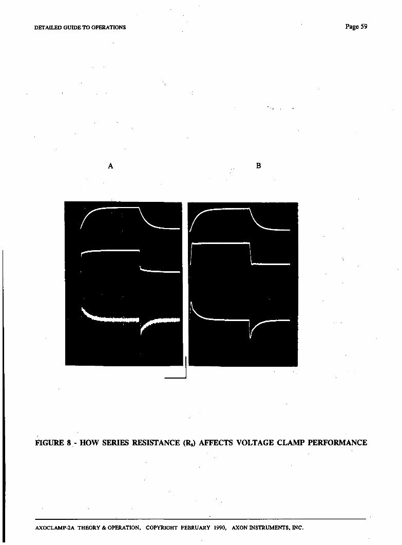
DETAILED GOTDE TO OPERATIONS Page 59
B
nOURE 8 - HOW SERIES RESISTANCE (Rg) AFFECTS VOLTAGE CLAMP PERFORMANCE
AXOCLAMP-2A THEORY & OPERATION, COPYRIGHT FEBRUARY 1990, AXON INSTRUMENTS, INC.
Page 6 0 DETAILED GUnJE TO OPERATIONS
SEVC MODE - CONTINUOUS
Continuous single-elecfrode voltage clamping (cSEVC) is one of two single-elecfrode voltage clamp modes. In cSEVC current pasising and voltage recording are performed simultaneously as shown in die block diagram of Fig. 9. The voltage (Vi) recorded by the microelecfrode buffer (Al) is compared in a high-gain differential amplifier (A2) to a command potential (Vc). The output of A2 acts to keep the difference at its input (e\) very small. Hence, Vi is clamped equal to Vc.
The circuit clamps the voltage across the microelecfrode (MEl) as well as the membrane potential (Vm). The voltage across MEl is non-zero because of the current (Im) which flows through it. This voltage drop is equal to the product of Im and the resistance (Rei) of MEl.
To keep the error due to ImRei small it is necessary that Rei be much smaller than the membrane resistance (Rm). Thus a 3 MQ microelectrode would be appropriate for use widi a 3(X) MQ cell.
The voltage across MEl can be partially compensated by using the Bridge potentiometer. Note that the range of die Bridge potentiometer is ten times less in cSEVC mode than in Bridge mode. The reduced range is indicated by a small LED. It is not normally possible to compensate more than about 70% of the elecfrode resistance without introducing oscillations.
During cSEVC, Rei has the nature of a series resistance (Rg). Rg is discussed in the Series Resistance Section.
Important Note - Anti-Alias Filter
The Anti-Alias Filter is not recommended for use in cSEVC mode. The reasons why are the same as those given in the TEVC Section.
Suggested Use
In Bridge mode set the Capacitance Neutralization control for the best step response.
Set die Gain and Anti-Alias Filter to minimum values. Switch the Phase control off. Switch off all current commands.
Use the Holding Position control to yield equal brightness in each of the two RMP Balance lights. At this setting the command potential during voltage clamp will be equal to the resting membrane potential (RMP). Lock the Holding Position control if desired.
Switch into cSEVC mode. Set up a repetitive step command. Monitor 10.Vm and !„• For maximum stabUity switch the Phase Time Constant to 20 or 200 ms. Increase the Gain for the best response on bodi Vm and Im- Sometimes lower current noise can be achieved for the same step response with the Phase Time Constant on 0.2 or 2 ms. Before switching to these values reduce the Gain since the stability margin is lower for smaller values of the Time Constant. Advance the Bridge potentiometer to speed up. the current and voltage setding times.
An example of a cSEVC set up in a cell model is shown in Fig. 10. The cell model was 300 MQ//33 pF and the elecfrode was modeled by a 3 MQ resistor. Because of Re there was a limit to how fast the membrane c^acitance could be charged. This can be seen from the duration of the capacitance fransient in the upper trace. The clamping electrode (MEl) records die tme membrane potential as well as the IR drop across itself, thus the step response of the recorded voltage (middle trace) is faster than the tme membrane potential (lower trace) recorded by an independent elecfrode. As discussed in the Series Resistance section, the time course of the tme membrane potential corresponds to the time course of the membrane current.
AXOCLAMP-2A THEORY &. OPERATION, COPYRIGHT FEBRUARY 1990, AXON INSTRUMENTS, INC.
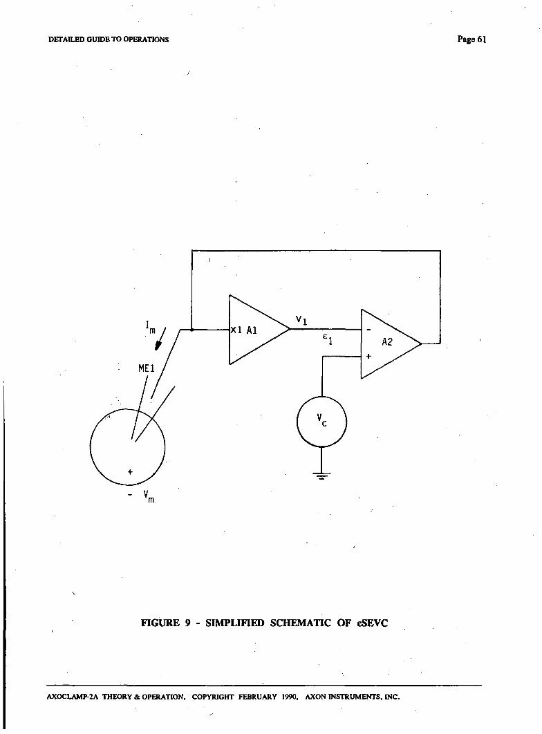
DETAILED GUIDE TO OPERATIONS Page 61
- V m.
FIGURE 9 - SIMPLinED SCHEMATIC OF cSEVC
AXOCLAMP-2A THEORY & OPERATION, COPYRIGHT FEBRUARY 1990, AXON INSTRUMENTS, INC.
Page 62 DETAILED GUIDE TO OPERATIONS
cSEVC Compared With Whole-Cell Patch Clamp
The simplified schematic in Fig. 9 shows that cSEVC is similar to whole-cell clamping using the patch-clamp technique. However the implementation is very different.
In the patch-clamp technique die voltage-clamp is established by a specialized headstage containing a virtual-ground circuit. In the cSEVC technique the headstage is a general-purpose unity-gain buffer and the voltage-clamp circuit is located in the main unit.
This difference is significant. In the dedicated virtual-ground headstage much less circuitry is involved and thus nonidealities of the electronics have much less effect. Thus for fast events the patch-clamp technique is considerably better than cSEVC. On the other hand for slow and moderate events the techniques become comparable.
Fig. 10
Current and potential recorded during cSEVC. Cell model was 300 MO//33 pf. Electrode was 3 MQ. Bandwidth was 3 kHz for all fraces. H of HS-2L headstage was xO.l. Clamp gain was 3.3 nA/mV. Voltage command was a 10 mV step. Phase Time Constant was 0.2 ms. Phase Shift was full lag. A-A Filter was off. Capacitance Neutralization was minimum.
Upper frace: Membrane current. Charging time was limited by Re.
Middle frace: Potential recorded by clamping elecfrode (MEl) and available at the 10.Vm ou^ut. Includes IR drop across MEl.
Lower trace: Tme membrane potential recorded by an independent electrode. Time course is the same as diat of die membrane current.
Noise: The current noise in the 3 kHz bandwidth was 55 pA peak-to-peak. If the gain was reduced so that the capacitance transient took 1.5 ms to setde the current noise fell to 12 pA peak-to-peak. The noise looks worse in the photo due to blooming of the photographed oscilloscope frace.
AXOCLAMP-2A THEORY St. OPERATION, COPYRIGHT FEBRUARY 1990, AXON INSTRUMENTS, INC.
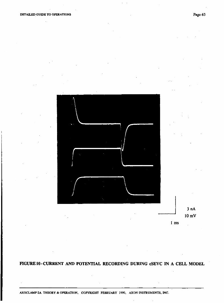
DETAILED GUIDE TO OPERATIONS Page 63
3nA
10 mV
1 ms
FIGURE 10-CURRENT AND POTENTIAL RECORDING DURING cSEVC IN A CELL MODEL
AXOCLAMP-2A THEORY & OPERATION, COPYRIGHT FEBRUARY 1990, AXON INSTRUMENTS, INC.

Page 64 DETAILED GUIDE TO OPERATIONS
SEVC MODE - DISCONTINUOUS
Description
In discontinuous single-electrode voltage clamp (dSEVC) mode the tasks of voltage-recording and current-passing are allocated to the same elecfrode. Time-sharing techniques are used to prevent interactions between the two tasks. The principles of operation have been published (Brenneke & Lindeniannn, 1974; Wilson & Goldner, 1975; Finkel & Redman, 1984) and are oudined in the block diagram and timing diagram of Fig. 11, and in the following discussion.
A single microelecfrode (MEl) penefrates the cell and the voltage recorded (Vi) is buffered by a unity-gain headstage (Al). To begin the discussion assume diat at this moment Vi is exacdy equal to the instantaneous membrane potential (Vm). A sample-and-hold circuit (SHl) samples Vm and holds it for the rest of the cycle.
The sampled membrane potential is compared with a command voltage (Vc) in a differential amplifier (A2). The output of this amplifier becomes die input of a controlled-current source (CCS) if the switch SI is in the current-passing position. The gain of the CCS is Gr.
The CCS injects a current into the microelectrode which is directly proportional to the voltage at die input of the CCS irrespective of die resistance of the microelecfrode.
The period of current injection is illusfrated at the start of the timing waveform. SI is shown in the current-passing position during which a square pulse of current is injected into the microelecfrode. Because of this current Vi rises.
The rate of rise is limited by the parasitic effects of die capacitance dirough the wall of the glass microelecfrode to the solution, and the capacitance at the input of the buffer amplifier. The final value of Vl mosdy consists of die IR voltage drop across the microelectrode due to the passage of current lo through the microelecfrode resistance Re. Only a tiny fraction of Vi consists of the membrane potential recorded at the tip.
SI then switches to the voltage-recording position. When the input of die CCS is 0 volts, its output current is zero and Vi passively decays. During the voltage-recording period Vi decays asymptotically towards Vm. Sufficient time must be allowed for V] to reach within a millivolt or less of Vm. This requires a period of up to 9 electrodes time constants (re). At die end of the voltage-recording period a new sample of Vm is taken and a new cycle begins.
The actual voltage used for recording purposes is the sampled voltage. As illustrated in the bottom timing waveform the sampled value of Vm moves in small increments about the average value. The difference between Vm(ave) and Vc is the steady-state error (ci) of the clamp which arises because the gain (Gr) of the CCS is finite. The error becomes progressively smaller as GT is increased.
The duty cycle used in dSEVC is current passing for 30% of each cycle, and voltage recording for 70% of each cycle.
The cycling rate (sample rate) must be chosen so that there are ten or more cycles per membrane time constant. This enables the membrane capacitance to smooth the membrane voltage response to the current pulses.
When optimally adjusted, the circuit enables the first steady-state measurement of voltage to be taken 1 to 2 cycle periods after the onset of a membrane conductance change or a change in the command voltage.
AXOCLAMP-2A THEORY & OPERATION, COPYRIGHT FEBRUARY 1990, AXON INSTRUMENTS, INC.
DETAILED GUTOE TO OPERATIONS Page 65
Two controls not shown in die Figure are the Anti-Alias Filter and the Phase control. The Anti-Alias Filter is a single-pole filter between the output of die unity-gain headstage (Al) and SHI (see Fig. 7). It can be used to reduce noise at a given sampling frequency. The output of die Anti-Alias Fdter can be observed on the Monitor output. In practice it is this voltage, not Vi, which has to decay to Vm before a sample is taken. The Phase confrol ^ters the frequency response of the differential amplifier (A2). It can be used to compensate for the complicated frequency characteristics of a real cell.
The Gain confrol alters GT- Refer to the Specifications for its operating range.
While MEl is occupied by the dSEVC it is still possible to independendy use ME2. For example, ME2 could be used for recording from and stimulating other cells which make connections to the cell being voltage-clamped.
AXOCLAMP-2A THEORY & OPERATION, COPYRIGHT FEBRUARY 1990, AXON INSTRUMENTS, INC.
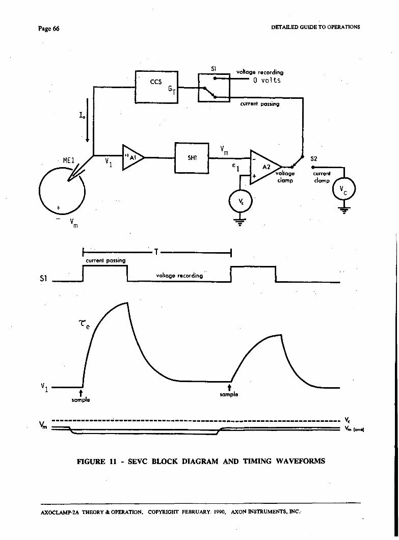
Page 66 DETAILED GUIDE TO OPERATIONS
vohoge recording
0 volts
S2
current clamp clomp
51
current passing
voltage recording
Vc
"m (ova) 17*=
FIGURE 11 - SEVC BLOCK DIAGRAM AND TIMING WAVEFORMS
AXOCLAMP-2A THEORY & OPERATION, COPYRIGHT FEBRUARY 1990, AXON INSTRUMENTS, INC.
DETAILED GUIDE TO OPERATIONS Page 67
Suggested Use
Use two oscilloscopes. To the main one connect the 10.Vm and Im outputs. Trigger this oscdloscope from the source used to time the command signals. To the second one (which need not be a high-quality type) connect the Monitor ou^ut. Set the gain to 100 mV/div (= 10 mV/div input referred). Trigger this oscilloscope from the SAMPLE CLOCK output on the rear panel.
Set up a repetitive current pulse in Bridge Mode. Balance the elecfrode voltage drop as shown in Fig. 2 in the Bridge Section.
Set Gain and Anti-Alias to minimum. Switch Phase Shift off (i.e. set Center Frequency to OFF).
Switch to DCC mode.
Proceed to optimally set the Ci4}acitance Neufralization as described in the DCC Section, method B, and illusfrated in Fig. 5.
Set the Output Bandwidth to 1/5 or less of fg.
Switch off the current pulse. Use the Holding Position control to achieve equal brightness in each of the two RMP Balance lights.
Switch to SEVC.
Set up a repetitive 10 mV step command.
Increase the Gain as far as possible without causing overshoot or instability in.the step response. Reduce the Gain slighdy below the maximum value to get a safety margin.
Introduce Phase lag or lead if by doing so the step response of both the current and the voltage can be improved.
Increase the Anti-Alias Filter while checking the settling characteristics on the monitor waveform. The noise on Vm and Im may be reduced by this procedure. Only use as much Anti-Alias as is consistent with stability.
Set the Anti-Alias Filter back to minimum before using a new electrode.
An example of a correcdy set up dSEVC is shown in Fig. 12.
AXOCLAMP-2A THEORY & OPERATION, COPYRIGHT FEBRUARY 1990, AXON INSTRUMENTS, INC.
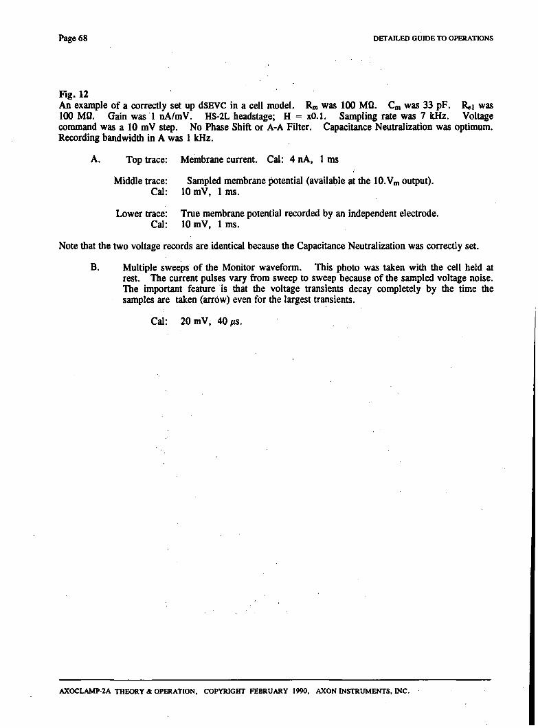
Page 68 DETAILED GumE TO OPERATIONS
Fig. 12 An example of a correcdy set up dSEVC in a cell model. Rm was 1(X) MO. Cm was 33 pF. Rei was 100 MQ. Gain was 1 nA/mV. HS-2L headstage; H = xO.l. Sampling rate was 7 kHz. Voltage command was a 10 mV s t^ . No Phase Shift or A-A Filter. Capacitance Neufralization was optimum. Recording bandwidth in A was 1 kHz.
A. Top frace: Membrane current. Cal: 4 nA, 1 ms
Middle trace: Sampled membrane potential (available at the 10.Vm output). Cal: 10 mV, 1 ms.
Lower frace: Tme membrane potential recorded by an independent elecfrode. Cal: 10 mV, 1 ms.
Note that the two voltage records are identical because the Capacitance Neufralization was correcdy set.
B. Multiple sweeps of the Monitor waveform. This photo was taken with the cell held at rest. The current pulses vary from sweep to sweep because of the sampled voltage noise. The important feature is that the voltage transients decay completely by the time the samples are taken (arrow) even for the largest transients.
Cal: 20 mV, 40/iS.
AXOCLAMP-2A THEORY & OPERATION, COPYRIGHT FEBRUARY 1990, AXON INSTRUMENTS, INC.
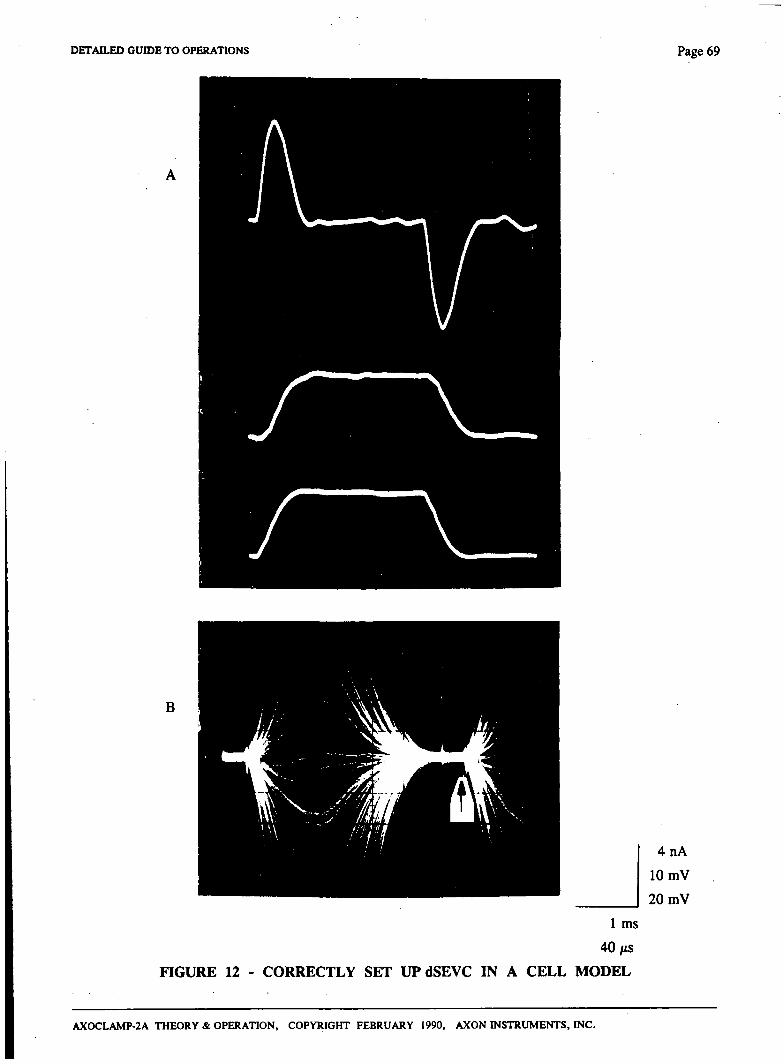
DETAn.£D GUIDE TO OPERATIONS Page 69
B
4nA
10 mV
20 mV
1 ms
40/iS
FIGURE 12 - CORRECTLY SET UP dSEVC IN A CELL MODEL
AXOCLAMP-2A THEORY & OPERATION, COPYRIGHT FEBRUARY 1990, AXON INSTRUMENTS, INC.
Page 7 0 DETAILED GUIDE TO OPERATIONS
Important Note
If the Phase controls are used it is possible to find false settings of Capacitance Neufralization (or the Anti-Alias Filter) and Phase which together give a seemingly fast step response to Vm whereas in fact the step response in the cell is much slower.
This situation arises by undemtilizing the Capacitance Neutralization (or ovemtilizing the Anti-Alias Filter) so that the Monitor waveform fails to decay adequately when the voltage sample is taken. The elecfrode voltage sampled has the nature of an IR drop across a series resistance (Rg; see Series Resistance Section). Normally this would make the clamp unstable, but by introducing phase lag stability can be re-imparted although without any reduction of die voltage error.
This false condition only arises if the Capacitance Neufralization setting is altered after the Phase control has been switched in. There are two ways to guarantee diat this false condition will not occur.
1. Don't use the Phase controls.
2. If the Phase controls are used be sure to conscientiously observe the Monitor waveform to make sure that the decay to a horizontal baseline is complete at the end of each cycle.
An example of a false clamp is shown in Fig. 13.
The recorded value of Im is always a tme measure of the membrane current even during diis false setting. Only the Vm record is erroneous. The danger of this false condition is diat most of the presumed membrane potential is in fact voltage drop across the microelectrode.
Which SEVC to use with a Suction Electrode
In the previous section we discussed how a continuous SEVC can be implemented by taking advantage of the low resistance of a suction electrode.
The problem with the cSEVC technique is the error introduced by Re which can only be partially overcome by series resistance compensation. This problem can be completely avoided by using the dSEVC mode.
It turns out that the conditions when a suction electrode is used are ideal for dSEVC. That is , because Re is very small the electrode time constant is fast. In addition, the magnitude of the voltage transient across the electrode for a given current is proportional to Re and dierefore small when Re is small. This double advantage of low Re values means that die dSEVC can be cycled very rapidly widiout introducing a sampling error.
Fig. 14 shows the result of a dSEVC in exacdy the same cell model that was used in the cSEVC shown in Fig. 0. The most significant difference in the set-up besides the clamping mode used was the fact that no phase shift was used in the dSEVC.
Since die IR drop across the electrode was not sampled, die recorded potential during dSEVC had the same time course as the membrane current and the tme membrane potential recorded by an independent elecfrode (not shown).
The disadvantage of the dSEVC mode was the additional current noise.
AXOCLAMP-2A THEORY & OPERATION. COPYRIGHT FEBRUARY 1990, AXON INSTRUMENTS, INC.
DETAILED GUHJE TO OPERATIONS Page 71
Fig. 13
An example of an incorrecdy set up dSEVC (i.e. a "false" clamp) in a cell model. Rm, Cm, Rei, Gain, H, sampling rate, recording bandwiddi and A-A Filter were the same as in Fig. 12. Phase Shift was at maximum lag. Time Constant was 2 ms. Capacitance Neufralization was under-utilized.
A. Top frace: Membrane current. Cal: 1 nA, 4 ms.
Note that this membrane current is much smaller and slower than the one in Fig. 12.
Middle frace: Sampled membrane potential (available at the 10. Vm output).
Cal: 10 mV, 4 ms.
Lower trace: Tme membrane potential recorded by an independent electrode.
Cal: 10 mV, 4 ms.
Note that the two voltage records are not die same. The sampled membrane potential includes a large error due to the voltage across the microelectrode at the sampling time (see B below).
B. Multiple sweeps of the Monitor waveform. This photo was taken with the cell held at .-1-50 mV 'from rest. (This was done because when the cell was held at rest with the considerable amount of phase lag used the noise current pulses were too small to allow the adequacy of the decay to be seen.) The voltage transients did not decay to a horizontal baseline at the times the samples were taken (arrow), therefore the samples included some of the IR voltage drop across the microelectrode.
AXOCLAMP-2A THEORY & OPERATION, COPYRIGHT FEBRUARY 1990, AXON INSTRUMENTS, INC.
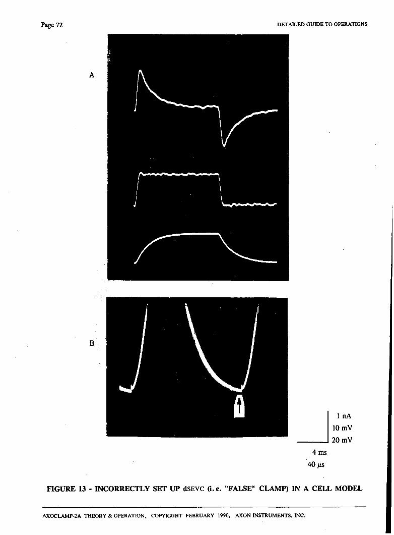
Page 72 DETAILED GUIDE TO OPERATIONS
B
4 ms
40/iS
1 nA
10 mV
20 mV
FIGURE 13 - INCORRECTLY SET UP dSEVC (i. e. "FALSE" CLAMP) IN A CELL MODEL
AXOCLAMP-2A THEORY & OPERATION, COPYRIGHT FEBRUARY 1990, AXON INSTRUMENTS, INC.
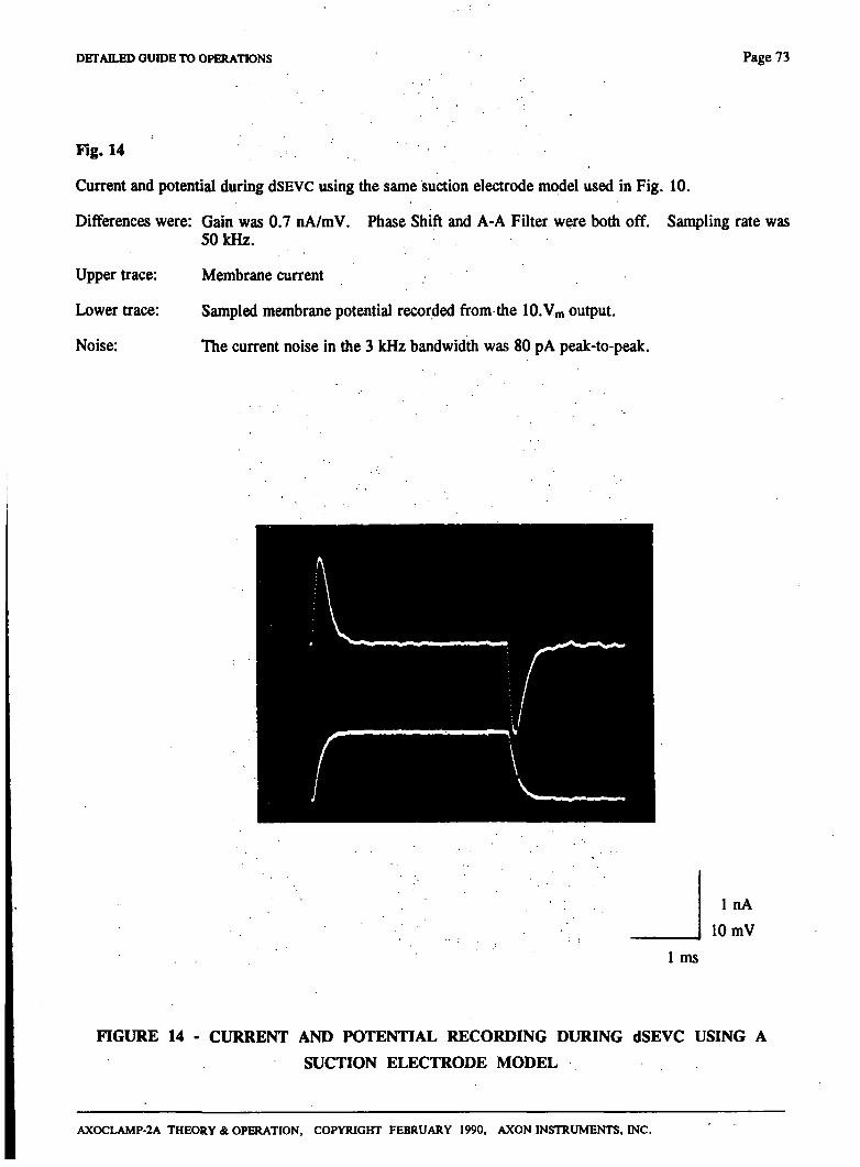
DETAILS) GUIDE TO OPERATIONS Page 73
Fig. 14
Current and potential during dSEVC using the same suction elecfrode model used in Fig. 10.
Differences were: Gain was 0.7 nA/mV. Phase Shift and A-A Filter were both off. Sampling rate was 50 kHz.
Upper frace: Membrane current
Lower frace: Sampled membrane potential recorded from the 10.Vm output.
Noise: Hie current noise in the 3 kHz bandwiddi was 80 pA peak-to-peak.
1 nA
10 mV
1 ms
FIGURE 14 - CURRENT AND POTENTIAL RECORDING DURING dSEVC USING A
SUCTION ELECTRODE MODEL
AXOCLAMP-2A THEORY & OPERATION, COPYRIGHT FEBRUARY 1990, AXON INSTRUMENTS, INC.
Page 7 4 DETAILED GUIDE TO OPERATIONS
Minimum Sampling Rate and Maximum Gain
If the sampling rate is too slow the dSEVC will become unstable. This is because the long current-passing period allows the the membrane potential to charge right through and past the desired potential before the clamp has an opportunity to take a new sample of potential and adjust die current accordingly. The larger the cell membrane capacitance (Cm) die slower the sampling rate (fg) which can be used for a given average gain (G). The stability criterion is (see Brenneke & Lindemann, 1974; Finkel & Redman, 1984)
G 0 < < 2
»^m tg
For critical damping we require
t.'m Ig
= 1
Thus for a given G, if Cm is small fg must be large.
As an example, if G = 1 nA/mV and Cm = iOO pF, dien fg must be 10 kHz for critical damping. If fg is less than 10 kHz in this example, the step response will overshoot and at 5 kHz the clamp will oscillate destmctively.
If the sampling rate in this example cannot be as great as 10 kHz because the microelecfrode response is too slow, then a lower value of G will have to be used to maintain stability.
Clamp Error
With finite gains in die voltage clamp circuit Vm does not quite follow Vc. The error is
£1 = Vc-Vm
Similarly, if Vc is constant and the cell membrane conductance changes there is an error in the measurement of the current underlying the conductance change. This error is similar in percentage to the voltage error.
Usually the gain of the voltage clamp circuit can be increased so that ei is 10% or less. The percentage error d^ends on the frequency of the command signal or of the conductance change. It is smallest for slow signals and DC, and largest for the fastest signals. Thus very fast transients (such as the rising phase of synaptic currents) will be clamped less well than slower transients (such as the decay phase of synaptic currents).
Gain
The clamp gain during dSEVC mode is given in nA/mV. This refers to how many nanoamps the output current will change by for each millivolt of difference between Vm (die membrane potential) and Vc (the command potential). The value indicated on die front panel is the average value. The average value depends upon the instantaneous gain during the current-passing period and upon the duty-cycle.
AXOCLAMP-2A THEORY SL OPERATION, COPYRIGHT FEBRUARY 1990, AXON INSTRUMENTS, INC.
DETAILED GUIDE TO OPERATIONS Page 75
SPACE CLAMP
When interpreting the current measured during voltage clamp, due consideration should be given to the adequacy of the spatial extent of the membrane voltage confrol.
In general, measurements of currents generated more than 0.1 elecfrotonic lengths from the point of the voltage clamp elecfrode(s) will be subject to significant error. This problem is discussed in detail by Johnston and Brown (1983).
TEN-TURN POTENTIOMETERS
The ten-tum potentiometers used in die AXOCLAMP-2A are high-quality wirewound types.
An inherent problem of wirewound potentiometers is that the wire elements tend to oxidize. This condition is curable.
If a potentiometer becomes noisy, the potentiometer manufacturer recommends rapidly spinning the knob 20-30 times between full clockwise and fiill counterclockwise. This clears the oxide off die element and restores noise-free operation.
TEVC MODE
Description
In TEVC (Two-Elecfrode Voltage Clamp) mode the AXOCLAMP-2A acts as a conventional voltage clampi. MEl is the voltage-recording elecfrode and ME2 is the current-passing electrode.
The ou^ut of die clamp is a voltage source (in contrast to SEVC modes in which the clamp ou^ut is a current source) which is connected to ME2. The voltage-clamp gain control is marked in units of V/V. This refers to how many volts the output will change by for each volt of difference between Vm (the membrane potential) and Vc (the command potential). For example, when the gain is at its maximum value of 10,000 V/V, a 100 yiV difference between Vm and Vc would cause the output to shift by 1 V. If die resistance of ME2 was 10 MO diere would be a current of 100 nA.
The best settings of the voltage-clamp parameters are found by setting up the best possible response to a step change in Vc. Usually, the abUity of the voltage clamp to follow a.step change in command is identical to the ability of the voltage clamp to follow a step change in membrane conductance (Finkel & Gage, 1985).
AXOCLAMP-2A THEORY & OPERATION, COPYRIGHT FEBRUARY 1990, AXON INSTRUMENTS. INC.
Page 76 DETAILED GUIDE TO OPERATIONS
Factors affecting the voltage-clamp response are these:
The Gain control determines the steady-state accuracy and the response speed.
The Phase control introduces a combination of phase lag and phase lead (a zero) in the voltage-clamp amplifier.
Hie Holding Position control shifts the clamped membrane potential.
Hie Capacitance Neufralization setting of MEl affects the voltage-clamp response. The Capacitance Neufralization setting of ME2 affects the current monitoring circuit at high frequencies and also has a small effect on the voltage-clamp response.
The Anti-Alais filter slows the microelecfrode response and should not be used in TEVC mode.
Suggested Use
In Bridge mode set the Capacitance Neutralization of each microelectrode for the best step responses. This is important but not critical, and in order to be tolerant of changes in the microelecfrodes' resistances which might occur during TEVC it is suggested that Capacitance Neutralization should be slighdy undemtilized.
Use a second-order or better lowpass filter to remove the high-frequency noise from I2 (see Ou^ut Filter section).
Set the Gain and Anti-Alias Filter to minimum values. Switch the Phase control off. Switch off all current commands.
Use the Holding Position control to yield equal brightness in each of the two RMP Balance lamps. At this setting the command potential during voltage clamp will be equal to the resting membrane potential (RMP). Lock the Holding Position control if desired.
Switch into TEVC mode. Set up a repetitive step command. Monitor both lO.Vm and I2. Increase the Gain as far as possible without causing overshoot in the s t ^ response. In cells whose membranes do not cause the same phase shift (90°) as a parallel RC cell model, the Phase control can be used to increase the maximum gain achievable. The Capacitance Neutralization setting of MEl should not be altered during voltage clamp unless there is reason to believe the resistance of MEl has altered.
Elxtremely Important Note - Coupling Capacitance
The most significant factor in achieving a good two-electrode voltage clamp is adequate prevention of interactions between the two electrodes. Coupling capacitance as low as 0.01 pF can destablize the response at high gain settings. f?
To minimize the coupling capacitance it is essential that a grounded shield be placed between the two microelectrodes and their headstages to prevent signals in ME2 being picked up by MEl. It should extend between the two elecfrodes to within a millimeter of the surface of the solution. It is possible to coat ME2 with a conductive paint which is then grounded. This procedure works well but has a minor disadvantage in that it vasdy increases the capacitance at the input of the ME2 headstage, which may affect the high-frequency measurement of h unless the capacitance neutralization of ME2 is properly set.
AXOCLAMP-2A THEORY & OPERATION, COPYRIGHT FEBRUARY 1990, AXON INSTRUMENTS, INC.
DETAn.ED GinDE TO OPERATIONS Page 77
Fig. IS shows the defrimental effects of only a small amount of coupling capacitance. The fraces in Fig. ISA show the membrane current and voltage responses in a cell model when an extensive grounded shield was placed between the two elecfrodes. In Fig 15B a 2-3 mm wide gap in the shield caused high-frequency oscillations and noise. The back end of the electrodes were 40-50 mm ^ a r t . When the gap size was increased further the clamp went unstable.
Figure 15
The destabilizing effects of coupling capacitance. Traces were recorded in a cell model; Rm = 10 MO, Cm = 1 nF, Rei = Re2 = 10 MO, Gain = 1000 V/V, recording bandwiddi = 10 kHz, Phase Shift and Anti-Alias Filter both off. 10 mV s t ^ conunand. Upper fraces are I2 (the membrane current). Lower fraces are Vm. Elecfrodes were 40-50 mm apart.
A. Extensive grounded shielding between the two elecfrodes.
B. 2-3 mm gap in the grounded shield caused high-frequency oscillations.
AXOCLAMP-2A THEORY & OPERATION, COPYRIGHT FEBRUARY 1990, AXON INSTRUMENTS, INC.
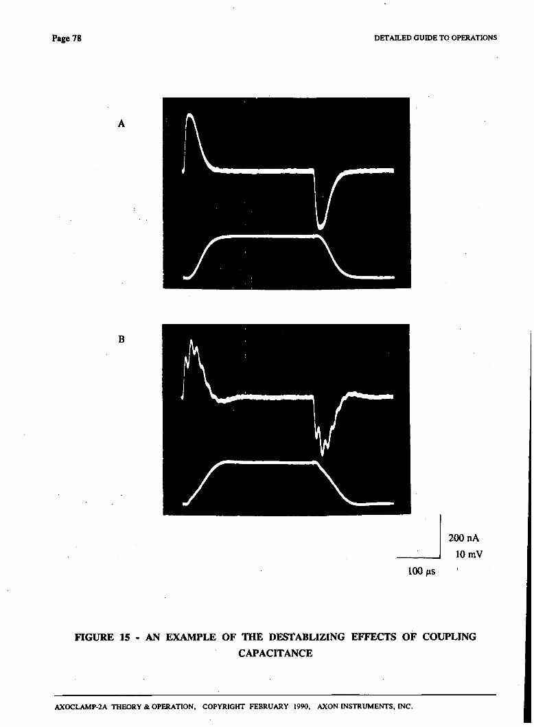
Page 78 DETAn,ED GUIDE TO OPERATIONS
B
200 nA
10 mV
100 MS
FIGURE 15 - AN EXAMPLE OF THE DESTABLIZING EFFECTS OF COUPLING
CAPACITANCE
AXOCLAMP-2A THEORY & OPERATION, COPYRIGHT FEBRUARY 1990, AXON INSTRUMENTS, INC.
DETAILED GUIDE TO OPERATIONS Page 79
Saturation During The Capacitance Transient
The output voltage of the AXOCLAMP-2A main unit during TEVC is ±30 V. This is usually sufficient to drive the current through ME2 required to charge the membrane capacitance during a step voltage change. However, for large stqis in some cells the output niay saturate and the time required to establish the step change will be longer than necessary.
Part of die reason for the saturation is that not all of the ±30 V appears across the microelectrode. Some of it appears across the current-sensing resistor (Ro; see Fig. 4) in the headstage. If Re = Ro then ± 15 V appears across the microelectrode, but if Re < Ro the voltage across the microelectrode is even less.
To overcome this a headstage (designated HS-4) is available which has a relay inside it to automatically link out Ro whenever TEVC mode is selected. There are two advantages to using the HS-4 headstage. The first is that even in the linear operating region the time to establish a step voltage change is quicker, and die second is that larger step changes can be established widiout entering the nonlinear (i.e. saturating) region. The disadvantage is that the HS-4 headstage must be used in conjunction with a virtual-ground current-measurement headstage. This is because the normal built-in current monitors need Ro in order to operate.
Because it requires a virtual-ground headstage as well, we do not normally recommend the HS-4 headstage unless the experimental circumstances demand it. Contact Axon Instmments for more details.
Choosing the Microelectrode Resistances
If large currents must be passed, such as may occur during large depolarizations of excitable cells, then the resistance of ME2 should be as low as possible. If low-noise recordings are required, which would be necessary for resolving small transmitter-activated currents from the background noise, dien the resistance of MEl should be as low as possible.
If two headstages with different Hs are used, the one with the larger H (and therefore greater current-passing ability) should be used with ME2.
TRIGGERED CLAMPING
In some experiments it is desirable to switch into voltage clamp only when a specific event threshold is reached. For examjple, it may be desirable to switch into voltage clamp when the undamped action potential goes above a predetermined level.
To do this an extemal device must be used to detect the event and signal its occurrence by putting out a logic HIGH. The logic HIGH is then applied to pin 5 or 6 of die Remote connector on the rear panel of die AXOCLAMP-2A. The AXOCLAMP-2A will then remain in voltage clamp mode until die logic HIGH is removed from pin 5 or 6 and a separate logic HIGH applied to pin 3 or 4 of die Remote connector.
AXOCLAMP-2A THEORY & OPERATION, COPYRIGHT FEBRUARY 1990, AXON INSTRUMENTS, INC.
Page 80 DETAILED GUIDE TO OPERATIONS
TROUBLE SHOOTING
It has been our experience at Axon Instmments that the majority of froubles rq>orted to us have been caused by faulty equipment connected to our instmments.
If you have a problem, please disconnect all instmments connected to the AXOCLAMP excqit for the oscilloscope and one headstage. Ground the headstage through the original test resistor supplied by Axon Instmments. If the problem persists, please call us for assistance.
UNITY-GAIN RECORDING - THIRD POINT
In normal operation both MEl and ME2 can be used for unity-gain recording and current-passing. A diird point in the preparation can be recorded from if virtual-ground current measurement is not being used. To do so, a unity-gain headstage (HS-2) is plugged into the Virtual-Ground connector on the rear panel. The voltage recorded spears on the rviRT output. No current can be passed via the HS-2 headstage used in the Virtual-Ground connector. When plugged into the Virtual-Ground connector the input capacitance of the unity-gain headstage is 4 pF.
VIRTUAI^GROUND CURRENT MEASUREMENT
A Virtual-Ground headstage can be used to ground the preparation badi. All of the current flowing into the Virtual-Ground input is measured and a voltage proportional to the current is provided at the IVIRT output. The output gain is 10 mV/nA when the virtual-ground output attenuation (VG) is xl , 1 mV/nA when VG is xlO, and 100 mV/nA when VG is xO.l
A Virtual-Ground headstage is not required for normal use of the AX0CLAMP-2A because built-in current-measurement circuits are provided for each microelectrode. However, in TEVC mode the current output of the Virtual-Ground headstage has slighdy less high-frequency noise than die output of the built-in current-measurement circuit.
The Virtual-Ground circuit measures all currents into the preparation bath, hence special care must be taken to ensure that conducting connections to the preparation bath do not act as antennae which pick up hum. Saline-filled tubes act as excellent antennae. To prevent them carrying hum, long saline-filled tubes should have the saline pathway broken by an air-filled drip near the preparation.
More complete explanations and instmctions are provided with the VG series of headstages.
AXOCLAMP-2A THEORY & OPERATION, COPYRIGHT FEBRUARY 1990, AXON INSTRUMENTS, INC.
DETAn.ED GUIDE TO OPERATIONS Page 81
10.Vn, AND In^ OUTPUTS
The 10.Vm output is proportional to ten times die membrane potential (Vm)- It is derived from the potential (Vl) recorded by MEl. Initially Vi is amplified, then depending on the operating mode, one of two techniques is used to derive the 10.Vm signal from the amplified Vi signal. In Bridge mode, the Bridge Balance technique is used to counter the effect of voltage drop (IR voltage drop) across MEI during current passing so that only the membrane potential measured at the tip is passed to the lO.Vm output. In DCC or dSEVC mode samples of the amplified Vi signal are taken after the IR voltage drop across MEl due to the previous current pulse has completely decayed. Only the sampled values are passed to the lO.Vm output.
The maximum recording range of the 10.Vm output is ±600 mV referred to the input. This range is centered on the zero value set by use of the Input Offset control. In Bridge mode this range includes the IR drop even though the IR drop may not be seen because the Bridge Balance is correcdy set. The full ±600 mV input-referred range is available in DCC and dSEVC modes irrespective of die current.
The Im output is proportional to the membrane current. In Bridge, cSEVC and TEVC modes it is the continuous electrode current. In DCC and dSEVC modes, Im is found by sampling the current during the current-passing period and multiplying by the duty cycle.
AXOCLAMP-2A THEORY & OPERATION, COPYRIGHT FEBRUARY 1990, AXON INSTRUMENTS, INC.
SPECIFICATIONS Page 82
SPECIFICATIONS
MODES
Five main opanting modes selectable by color-coded illuminated push buttons, These are:
Discontinuous Current Clamp Discontinuous Single-Electrode Voltage Clamp Continuous Single-Electrode Voltage Clamp Two-Elecfrode Voltage Clamp
or remotely.
1. 2. 3. 4. 5.
Bridge DCC: dSEVC: cSEVC: TEVC:
MICROELECTRODE AMPLIFIERS (Two Channels)
Unity-Gain Headstages:
Hum (line-frequency pickup):
Headstage Current Gain (H):
Maximum Current:
Noise with grounded input:
Noise with a source resistance:
1% Settling Time:
Standard is the HS-2L type. HS-2M types arie die same except: 1) the noise is greater by about 20% 2) the capacitance neutralization range is extended.
HS-2MG types are similar to die HS-2M types except that the case is grounded instead of driven.
Less than 10 nW peak-to-peak, grounded input.
Available in 5 values (specify two widi order). Select on basis of cell input resistance (Rin) and maximum current capacity (Imax)-
H = xO.OOOl for ion-sensitive electrodes H = xO.Ol for Rin greater dian about 300 MO H = xO.l for Rin about 30-300 MO H = X 1 (standard) for Rin about 3-30 MQ H = xlO for Rin about 300 kO to 3 MQ
These ranges are suggested for optimum performance. Some overlap is allowable.
Imax = 1000 X H nA.
5 fiW rms measured with a 10 kHz single-pole filter in the measurement circuit.
51 (47) (iW rms measured with a 10(100) MQ source resistance and c^acitance neutralization adjusted for a 10(1) kHz bandwidth and with a 10 (1) kHz single-pole- filter in the measurement circuit. Values are for H = xl (xO.l), HS-2L headstage.
16(54) /ts for a voltage step applied to the input via a 10(100) Mfl low-capacitance resistor and 16(60) /is for a current step into the same resistor. Capacitance neutralization adjusted for zero overshoot. Values are for H = xl (xO.l).
AXOCLAMP-2A THEORY & OPERATION, COPYRIGHT FEBRUARY 1990, AXON INSTRUMENTS, INC.
SPECmCATIONS Page 83
Working Input Voltage Range: ± 13 V for transients and steady state, protected to ±30 V. Input Resistance: lO'-'-lO'* 0, H = x 0.0001 (see note)*
10»3 0, H = X .01 10'2 0, H = x0.1 10" 0, H = X 1 lO'O 0, H = X 10
*Note: For the xO.OOOl headstage, the input resistance of each headstage is measured individually. The unique test results are supplied with each xO.OOOl headstage.
Input Capacitance:
Input Leakage Current:
Input Leakage Current vs. Temperature:
Not relevant. See 1 % setding time and noise specifications.
Adjustable to zero.
Offset Neutralization Range:
Capacitance Neutralization Range:'
Buzz:
Buzz Duration:.
Clear:
Bridge Balance Range:
Digital Voltmeters:
10 100 1 10
fA/ fA/ pA/ pA/
°c. "C,
-c. "C,
H = xO.OOOl H = xO.Ol, xO.l H = xl H = xlO
±500 mV. Ten-tum potentiometers.
HS-2L: -1 to 7 pF HS-2M: -2to20pF HS-2MG: -4 to 18 pF
These values apply when headstage is used with microelecfrode 1 amplifier. With microelectrode 2 amplifier the maximum values are doubled.
Instandy increases capacitance neutralization to cause oscUlation. Operatol by spring-loaded pushbutton switch, footswitch or by Remote Buzz Duration control. The latter allows the Buzz duration to be set in the range 1-SO ms.
1-50 ms when activated by the remote buzz confrol.
Forces ±Imax through the microelectrode. Spring-loaded toggle switch.
10- H MO/turn in Bridge mode. Ten-tum potentiometers.
1+H MO/tura in cSEVC mode.
Voltage Displays: Current Displays:
±1999mV. ± 19.99 pA, ± 1.999 nA, ± 19.99 nA, ±199.9 nA, ±1.999 mA,
Scaling is set by miniature panel switches II, h a n d Ivin. Currents exceeding the digital display range can be measured on the BNC outputs.
Sq)arate meters for Vi and V2 H = X 0.0001 H = X .01 H = x.0.1 H = X 1 H = X 10
Display selections are
AXOCLAMP-2A THEORY & OPERATION, COPYRIGHT FEBRUARY 1990. AXON mSTRUMENTS. INC.
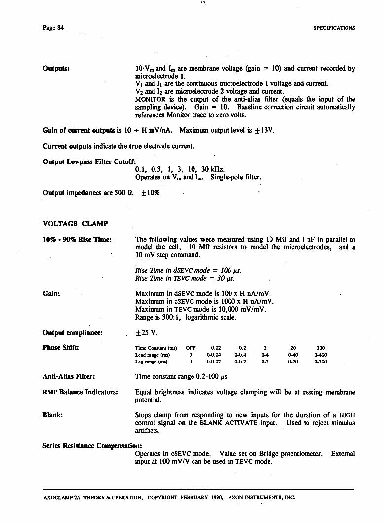
Page 84 SPECmCATIONS
Outputs: 10-Vm and Im are membrane voltage (gain = 10) and current recorded by microelecfrode 1. Vl and II are the continuous microelecfrode 1 voltage and current. V2 and I2 are microelecfrode 2 voltage and current. MONITOR is the output of the anti-alias filter (equals the input of the sampling device). Gain = 10. Baseline correction circuit automatically references Monitor trace to zero volts.
Gain of current outputs is 10 H- H mV/nA. Maximum ou^ut level is ± 13V.
Ciurent outputs indicate the true dectrode current.
Output Lowpass Filter Cutoff: 0.1, 0.3, 1, 3, 10, 30 kHz. Operates on Vm and Im. Single-pole filter.
Output impedances are 500 0. ± 10%
VOLTAGE CLAMP
10% - 90% Rise l ime:
Gain:
Output compliance:
Phase Shift:
Anti-Alias Filter:
RMP Balance Indicators:
Blank:
The following values were measured using 10 MO and 1 nF in parallel to model the cell, 10 MO resistors to model the microelecfrodes, and a 10 mV step command.
Rise Time in dSEVC mode = 100 us. Rise Tme in TEVC mode = 30 fis.
Maximum in dSEVC mode is 100 x H nA/mV. Maximum in cSEVC mode is 1000 x H nA/mV. Maximum in TEVC mode is 10,000 mV/mV. Range is 300:1, logarithmic scale.
±25 V.
Time Constant (ms) Lead range (ms) Lag range (ms)
OFF 0 0
0.02 0-0.04 0-0.02
0.2 0-0.4 (W).2
2 0-4 0-2
20 0-40 0-20
200 0-400 0-200
Time constant range 0.2-100 /is
Equal brightness indicates voltage clamping will be at resting membrane potential.
Stops clamp from responding to new inputs for the duration of a HIGH control signal on the BLANK ACTIVATE input. Used to reject stimulus artifacts.
Series Resistance Compensation: Operates in cSEVC mode. Value set on Bridge potentiometer. Extemal input at 100 mV/V can be used in TEVC mode.
AXOCLAMP-2A THEORY & OPERATION, COPYRIGHT FEBRUARY 1990, AXON INSTRUMENTS, INC.
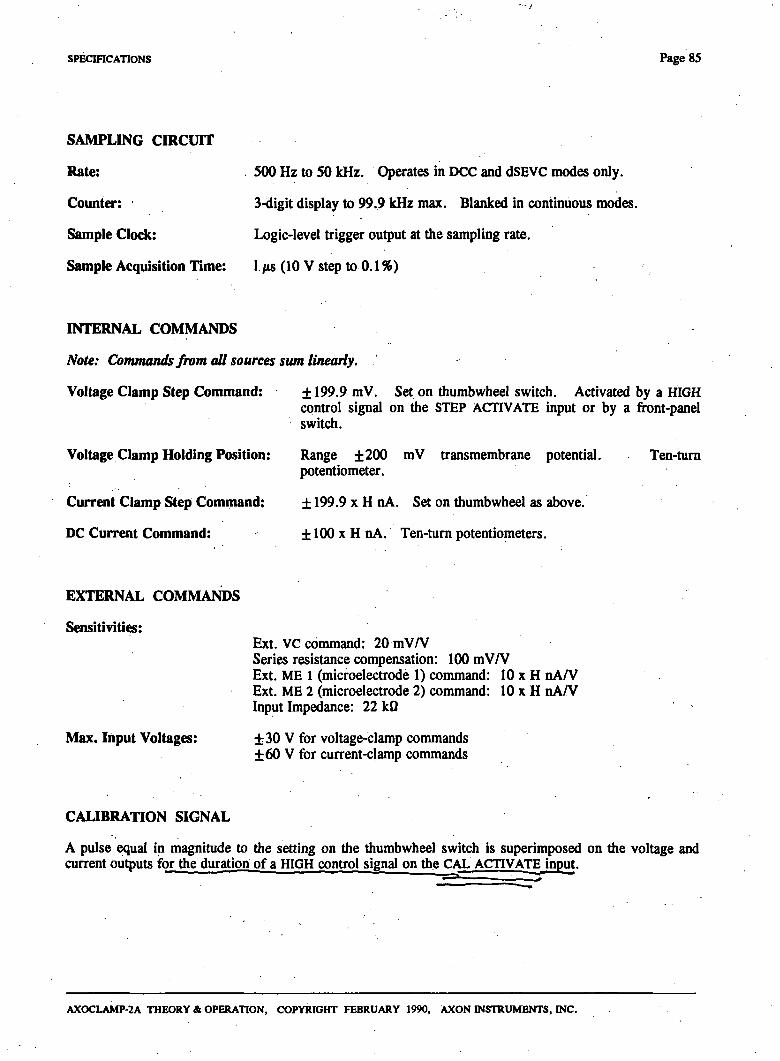
SPECmCATIONS Page 85
SAMPLING CIRCUIT
Rate:
Counter:
Sample Clodc
Sample Acquisition Time:
500 Hz to 50 kHz. Operates in DCC and dSEVC modes only.
3Hdigit display to 99.9 kHz max. Blanked in continuous modes.
Logic-level frigger output at the sampling rate.
l/«(10Vstepto0.1%)
INTERNAL COMMANDS
Note: Commands from all sources sum Uneaiiy.
Voltage Clamp Step Command:
Voltage Clamp Holding Position:
Current Clamp Step Command:
DC Current Command:
± 199.9 mV. Set on diumbwheel switch. Activated by a HIGH control signal on the STEP ACTIVATE input or by a front-panel switch.
Range ±200 mV transmembrane potential, potentiometer.
± 199.9 X H nA. Set on thumbwheel as above.
± 100 X H nA. Ten-tum potentiometers.
Ten-tum
EXTERNAL COMMANDS
Sensitivities:
Max. Input Voltages:
Ext. VC conunand: 20 mV/V Series resistance compensation: 100 mV/V Ext. ME 1 (microelecfrode 1) command: 10 x H nA/V Ext. ME 2 (microelectrode 2) command: 10 x H nA/V Input Impedance: 22 kO
±30 V for voltage-clamp conunands ±60 V for current-clamp commands
CALIBRA-nON SIGNAL
A pulse equal in magnitude to the setting on the thumbwheel switch is superimposed on the voltage and current ou juts for the duration of a HIGH control signal on the CAL ACTIVATE input.
AXOCLAMP-2A THEORY & OPERATION, COPYRIGHT FEBRUARY 1990, AXON INSTRUMENTS, INC.
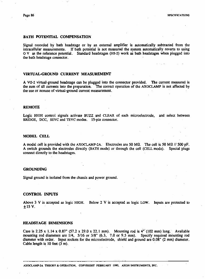
Page 86 SPECIFICATIONS
BATH POTENTIAL COMPENSATION
Signal recorded by badi headstage or by an extemal amplifier is automatically subfracted from die intracellular measurements. If bath potential is not measured the system automatically reverts to using O V as the reference potential. Standard headstages (HS-2) work as badi headstages when plugged into the bath headstage connector.
VIRTUAL-GROUND CURRENT MEASUREMENT
A VG-2 virtual-ground headstage can be plugged into the connector provided. Tlie current measured is the sum of all currents into the preparation. The correct operation of the AXOCLAMP is not affected by the use or nonuse of virtual-ground current measurement.
REMOTE
Logic HIGH control signals activate BUZZ and CLEAR of each microelectrode, and select between BRIDGE, DCC, SEVC and TEVC modes. 15-pin connector.
MODEL CELL
A model cell is provided widi die AXOCLAMP-2A. Electrodes are 50 MQ. The cell is 50 MO // 500 pF. A switch grounds the electrodes direcdy (BATH mode) or through the cell (CELL mode). Special plugs connect directly to the headstages.
GROUNDING
Signal ground is isolated from the chassis and power ground.
CONTROL INPUTS
Above 3 V is accepted as logic HIGH. Below 2 V is accepted as logic LOW. Inputs are protected to ±15 V.
HEADSTAGE DIMENSIONS
Case is 2.25 x 1.14 x 0.87" (57.2 x 29.0 x 22.1 mm). Mounting rod is 4" (102 mm) long. Available mounting rod diameters are 1/4, 5/16 or 3/8" (6.3, 7.0 or 9.5 mm). Specify required mounting rod diameter with order. Input sockets for die microelectrode, shield and ground are 0.08" (2 mm) diameter. Cable lengdi is 10 feet (3 m).
AXOCLAMP-2A THEORY & OPERATION, COPYRIGHT FEBRUARY 1990, AXON INSTRUMENTS, INC.
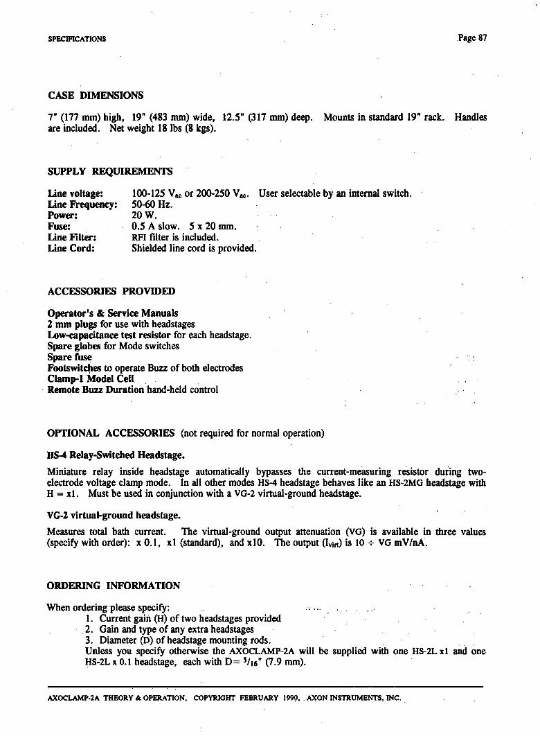
SPECffiCATiONS Page 87
CASE DIMENSIONS
T {Vll mm) high, 19" (483 mm) wide, 12.5" (317 mm) deep. Mounts in standard 19" rack. Handles are included. N ^ weight 18 lbs (8 kgs).
SUPPLY REQUIREMENTS
Une voltage: 100-125 Vac or 200-250 Vac. User selectable by an intemal switch. Line Frequency: 50-60 Hz. Power: 20 W. Fuse: 0.5 A slow. S x 20 mm. Line Filter: RFI filter is included. Line Cord: Shielded line cord is provided.
ACCESSORIES PROVIDED
Operator's & Service Manuals 2 mm plugs for use with headstages Low-capadtance test resistor for each headstage. Spare globes for Mode switches Spare fuse Footswitches to operate Buzz of bodi elecfrodes Clamp-1 Model Cell Remote Buzz Duration hand-held control
OPTIONAL ACCESSORIES (not required for normal operation)
HS-4 Relay-Switched Headstage.
Miniature relay inside headstage automatically bypasses the current-measuring resistor during two-elecfrode voltage clamp mode. In all odier modes HS-4 headstage behaves like an HS-2MG headstage widi H = xl. Must be used in conjunction with a VG-2 virtual-ground headstage.
VG-2 virtual-ground headstage.
Measures total bath current. The virtual-ground output attenuation (VG) is available in three values (specify with order): x 0.1, xl (standard), and xlO. The output (Ivin) is 10 -;- VG mV/nA.
ORDERING INFORMATION
When ordering please specify: 1. Current gain (H) of two headstages provided 2. Gain and type of any extra headstages 3. Diameter (D) of headstage mounting rods. Unless you specify otherwise the AXOCLAMP-2A will be supplied with one HS-2L xl and one HS-2L X 0.1 headstage, each witii D= ^k^" (7.9 mm).
AXOCLAMP-2A THEORY St. OPERATION, COPYRIGHT FEBRUARY 1990, AXON INSTRUMENTS, INC.

Page 88 sPEcmcATioNS
CThis page is intentionally left blank)
AXOCLAMP-2A THEORY & OPERATION, COPYRIGHT FEBRUARY 1990, AXON INSTRUMENTS, INC.
REFERENCES A-1
REFERENCES
Brennecke, R. & Lindemann, B. (1974). Theory of a membrane voltage clamp with discontinuous feedback dirough a pulsed current clamp. Rev. Sci. Instmm. 45, 184-188.
Finkel, A. S. & Gage, P. W. (1985). Conventional voltage clamping with two infracellular microelectrodes. In Voltage Clamping widi Microelectrodes, ed. T. G. Smidi, et al, Williams & Wilkins: Baltimore.
Finkel A. S. & Redman, S. J. (1985). Optimal voltage clamping widi a single microelectrode. In Voltage Clamping with Microelecfrodes, ed. T. G. Smith, et al, Williams & Wilkins: Baltimore.
Finkel, A. S. & Redman S. J. (1983). A shielded microelectrode suitable for single-elecfrode voltage clampingof neurons in the CNS. J. Neurosci. Meths. 9, 23-29.
Hamill, O.P., Marty, A., Sakmann, B. & Sigworth, F. J. (1981). Improved patch-clamp techniques for high-resolution current recording from cells and cell-free membranes patches. Pflugers Arch. 391, 85-100.
Johnston, D. & Brown, T. H. (1983). Interpretation of voltage-clamp measurements in hippocampal neurons. J. Neurophysiol. SO, 464^86.
j^Purves, R.D. (1981). Microelectrode Methods for Intracellular Recording and Ionophoresis. London: J , s^ Academic Press. - ^ =^ ^
Sachs, F. & McGarrigle, R. (1980). An almost completely shielded microelecfrode. J. Neurosci. Meths. 3, 151-157.
Schwartz, T. I & House, Randall C. (1970). A small-tipped microelectrode designed to minimize c^acitive artifacts during the passage of current through die badi. Rev. Sci. Inst. 41, 515-517.
Suzuki, K., Rohligek, V. & Frbmter, E. (1978). A quasi-totally shielded, low-capacitance glass-microelectrode with suitable amplifiers for high-frequency intracellular potential and impedance measurements. Pflugers Arch. 378, 141-148.
Wilson, W. A. & Goldner, M. M. (1975). Voltage clamping with a single microelectrode. J. Neurobiol. 6,411-422
AXOCLAMP-2A THEORY & OPERATION, COPYRIGHT FEBRUARY 1990, AXON INSTRUMENTS, INC.

A-2 REFERENCES
CThis page is intentionally left blank)
AXOCLAMP-2A THEORY & OPERATION, COPYRIGHT FEBRUARY 1990, AXON INSTRUMENTS, INC.
WARRANTY B- l
WARRANTY
We warrant every AXOCLAMP and every headstage to be free from defects in material and workmanship under normal use and service. For 12 months from the date of receipt we will repair or replace without cost to the customer any of these products that are defective and which are retumed to our factory properly packaged with transportation charges prepaid. We will pay for the return shipping of the product to the customer. If the shipment is to a location outside the United States, the customer will be responsible for paying all duties, taxes and Alight clearance charges if applicable.
Before returning products to our factory the customer must contact us to obtain a Retum Merchandise Authorization number (RMA) and shipping instructions. Failure to do so will cause long delays and additional expense to customer. Complete a copy of the RMA form on the next page and return it with the product.
This warranty shall not apply to damage resulting from improper use, improper care, improper modification, connection to incompatible equipment, or to products which have been modified or integrated with other equipment in such a way as to increase the time or difficulty of servicing the product.
This warranty is in lieu of all other warranties, expressed or implied.
Axon Instruments, Inc.
AXOCLAMP-2A THEORY & OPERATION, COPYRIGHT FEBRUARY 1990, AXON INSTRUMENTS, INC.

B-2 WARRANTY
CThis page is intentionally left blank)
AXOCLAMP-2A THEORY & OPERATION, COPYRIGHT FEBRUARY 1990, AXON INSTRUMENTS, INC.
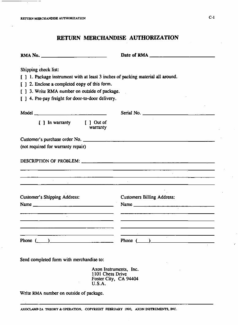
RETURN MERCHANDISE AUTHORIZATION C-1
RETURN MERCHANDISE AUTHORIZATION
RMA No. Date of RMA
Shipping check list: [ ] 1. Package instmment with at least 3 inches of packing material all around. [ ] 2. Enclose a completed copy of this form. [ ] 3. Write RMA number on outside of package. [ ] 4. Pre-pay freight for door-to-door delivery.
Model
[ ] In warranty [ ] Out of warranty
Serial No.
Customer's purchase order No. _ (not required for warranty repair)
DESCRIPTION OF PROBLEM:
Customer's Shipping Address: Name
Customers Billing Address: Name
Phone ( )_ Phone ( )_
Send completed form with merchandise to:
Axon Instruments, Inc. 1101 Chess Drive Foster City, CA 94404 U.S.A.
Write RMA number on outside of package.
AXOCLAMP-2A THEORY & OPERATION, COPYRIGHT FEBRUARY 1990, AXON INSTRUMENTS, INC.
C-2 RETURN MERCHANDISE AUTHORIZATION
m-. HARVEY J. KARTEN, M.D. UNIVl:RS!TY OF CALIFORNIA, SAN DIEGO l>PA&tMeNT OF NEUROSCItNaS, O&OS ^ 1 ^ OILMAN DRIVE iJK m i K 0 \ 92093-0608
CThis page is intentionally left blank)
AXOCLAMP-2A THEORY & OPERATION, COPYRIGHT FEBRUARY 1990, AXON INSTRUMENTS, INC.
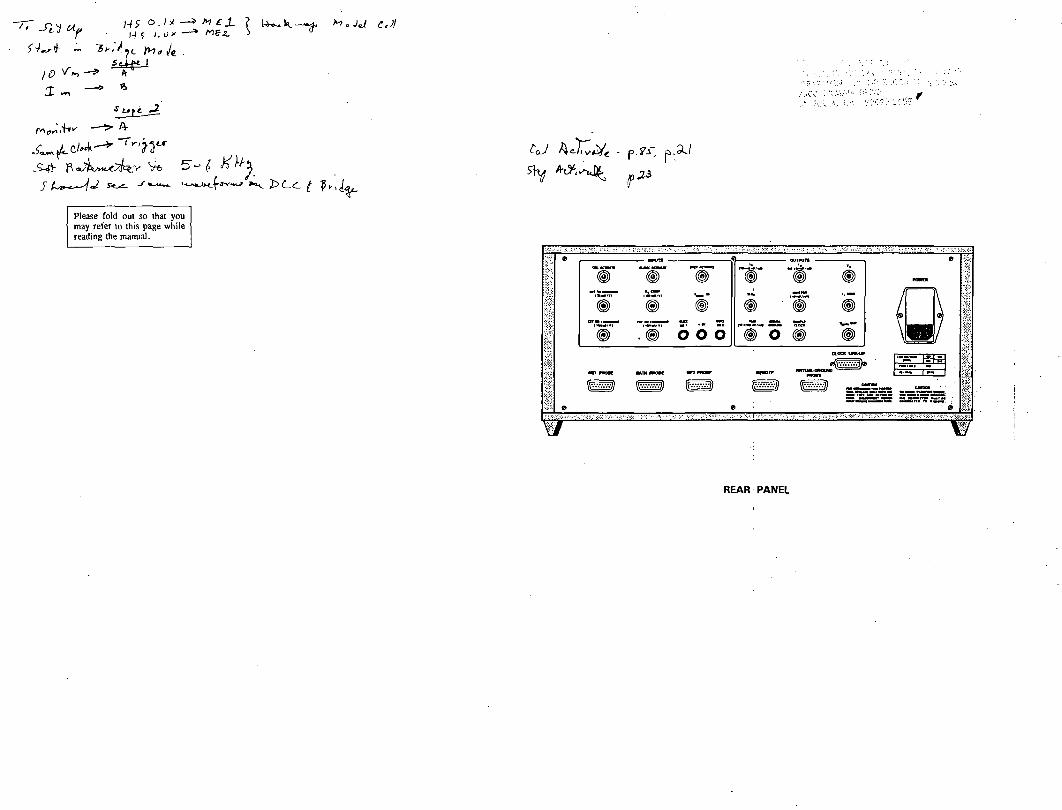
'•'^ r ] - i f 1 .0 " - ^ > ^ - J J ^ z*/
^
Please fold out so that you may refer to this page while reading the manual.
o o o m o m CLOai UMtW
um mt»t ms m
^ m < mi ^ m ^ p ^ p ss~!sx ^
REAR PANEL
CR. HAP>/fY J. KARTEN, W.nv .^ UNivresny o f CAUfORNiA, SAN P i r c b
1I:A •toa.^. OA •9.2093-0«<)8
'•'f j 1 l i t '• '• •"•'' •