Embed Size (px)
Citation preview
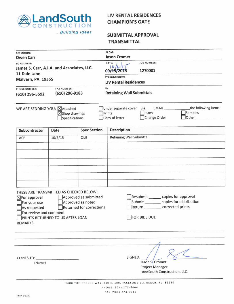

October 5, 2015
Mr. Ryan Yarbrough Associated Construction Products, Inc. (ACP) 25352 Wesley Chapel Boulevard Lutz, Florida 33559
Subject: Segmental Retaining Wall Analysis Championsgate Apartments Osceola County, Florida ACP Project No.: P-11989 Test Lab Project No.: GE-15-4353
Dear Mr. Yarbrough:
As authorized, Test Lab, Inc. (Test Lab) has completed the segmental retaining wall analysis and prepared Plans and Specifications for the project referenced above. These Plans and Specifications have been prepared for your exclusive use, and for specific application to the referenced project. This report may not contain sufficient information for other uses or for the purposes of other parties; therefore, we cannot assume responsibility for conclusions or recommendations based upon this data made by others.
We appreciate the opportunity to have been of service. If there are any questions concerning this analysis, or if we may be of any further assistance, please do not hesitate to contact us.
Sincerely, Test Lab, Inc. 4112 West Osborne Avenue, Tampa, Florida Certificate of Authorization No. 1450
W. Sharkey Bowers, PE Project Engineer Florida License No. 78970
Attachment: Segmental Retaining Wall Plans
Draft Engineering
Not For Construction

Consulting Engineer:Test Lab, Inc.4112 West Osborne AvenueTampa, FL 33614Phone: (813) 872-7821
CHAMPIONSGATE APARTMENTSSEGMENTAL RETAINING WALL PLANS
OSCEOLA COUNTY, FLORIDA
P-11989
Client:LandSouth1680 The Greens Way, Suite 100Jacksonville Beach, FL 32250Phone: (904) 273-6004Fax: (904) 273-0040
Design and Install:Associated Construction Products, Inc.25352 Wesley Chapel Blvd.Lutz, FL 33559Phone: (813) 973-4425Fax: (813) 973-0485
Sheet Index
Draft Engineering
Not For Construction
SPECIFICATIONS FOR SEGMENTAL RETAINING WALL SYSTEM
SECTION 1: GENERAL
1.1 These Plans and Specifications have been prepared for the exclusive use of Associated Construction Products, Inc. (ACP), and for
specific application to the referenced project. This report may not contain sufficient information for other uses or for the purposes of
other parties; therefore, we cannot assume responsibility for conclusions or recommendations based upon this data made by others.
1.2 The following documents pertaining to the above noted project were reviewed and incorporated as applicable:
A Custom Soil Resource Report of Osceola County , prepared by the U.S. Department of Agriculture Natural Resource
Conservation Service (NRCS, formerly the Soil Conservation Service);
Sheet 07 of 25 of the Site Development Plans for Championsgate Apartments (Revision 1, dated 05/18/15, prepared by Hanson,
Walter & Associates, Inc. (Job No. 4832-17). This sheet is included with our drawings with the retaining wall location(s) highlighted
for your reference.
1.3 Wall locations shall be marked and staked by the Owner prior to start of this work.
1.4 All construction procedures shall meet the safety requirements of the Occupational Safety and Health Administration and other local,
state, and federal agencies, to protect life and property.
1.5 The contractor installing this wall shall be trained and certified as a SRW contractor by a local manufacturer or equivalent accredited
organization.
1.6 Work includes furnishing and installing segmental retaining wall (SRW) units to the lines and grades designated on the construction
drawings. Included also is furnishing and installing appurtenant materials required for construction of the retaining wall as shown on the
construction drawings.
1.7 This retaining wall design is in general accordance with the following design reference standards:
2014 Florida Building Code
National Concrete Masonry Association (NCMA) Design Manual for Segmental Retaining Walls - 3rd Edition.
1.8 Where specifications and reference documents conflict, the more stringent requirement shall apply.
1.9 Test Lab recommends that we be retained by the Owner to observe and provide testing during the wall construction.
SECTION 2: MATERIALS
2.1 Delivery, Storage and Handling
Contractor shall check materials upon delivery to assure that specified type and grade of materials have been received and proper
color and texture of SRW units have been received.
Contractor shall prevent excessive mud, wet concrete, epoxies, and like materials that may affix themselves, from coming in
contact with materials.
Contractor shall store and handle materials in accordance with manufacturer's recommendations.
Contractor shall protect materials from damage. Damaged materials shall not be incorporated into the retaining wall.
2.2 Segmental Retaining Wall Units
SRW units currently approved for this project are:
o Diamond Pro® units manufactured by Anchor Wall Systems, Inc.
Wall units shall have minimum 28 day compressive strength of 3,000 psi (20.7 MPa) in accordance with ASTM C1372.
Exterior dimensions shall be uniform and consistent. Maximum dimensional deviations on the height of any two units shall be 0.125
in. (3mm).
All units shall be sound and free of cracks or other defects that interfere with the proper placement of the unit or significantly impair
the strength or permanence of the construction. Minor cracks incidental to the usual method of manufacture or minor chipping
resulting from customary methods of handling in shipment and delivery are not grounds for rejection.
Where units are to be used in exposed wall construction, the face or faces that are to be exposed shall not show chips or cracks,
not otherwise permitted, or other imperfections when viewed from a distance of not less than 20 feet (6.1 meters) under diffused
lighting.
2.3 Geosynthetic Reinforcement
Geosynthetic reinforcement shall consist of geogrids or geotextiles manufactured as a soil reinforcement element. Geosynthetic
reinforcement products shall be of high density polyethylene or polyester yarns encapsulated in a protective coating specifically
fabricated for use as a soils reinforcement material. Geosynthetic types currently approved for this project are:
o Synteen SF-35 as manufactured by Synteen Technical Fabrics
The placement location of the reinforcing geosynthetic shall be as determined by the Engineer, as shown on the construction
drawings.
2.4 Reinforced (Infill) Soil
Infill soils are the soils used as fill for the reinforced soil mass. The reinforced soil material shall be free of debris. The reinforced
material shall consist of the inorganic USCS soil types GP, GW, SW, SP, and SP-SM with 12% or less fines (material passing the
#200 sieve).
The angle of friction for this material shall be a minimum of 32 degrees.
2.5 Leveling Pad, Drainage Aggregate, and Filter Fabric
Material for leveling pad and drainage aggregate shall consist of #57 or #67 crushed stone, 0.375 inches to 0.75 inches (9.5 mm -
19 mm) meeting the gradation as determined in accordance with AASHTO M 43.
The leveling pad shall be constructed as shown on the construction drawings.
The free draining aggregate shall be placed to a minimum of twelve (12) inches width behind the back of the wall and shall extend
vertically from the leveling pad to an elevation four (4) inches below top of wall.
Filter fabric shall consist of 6-oz. non-woven geotextile cloth. It shall be placed between the free draining backfill and retained soil.
2.6 Drainage Collection Pipe and Outlet Pipe
The drainage collection pipe(s) and outlet pipe(s) shall be a 4-inch diameter corrugated high-density polyethylene (HDPE) pipe, or
an approved similar material. The drainage collection pipe must be perforated.
SECTION 3: PROJECT SPECIFIC DESIGN CRITERIA
3.1. This design is in general accordance with the National Concrete Masonry Association's Design Manual for Segmental Retaining Walls -
3rd Edition.
3.2. A minimum design live load surcharge equal to 60 pounds per square foot (psf) was placed behind the wall in our analysis at all
locations.
3.3. A design live load surcharge equal to 250 pounds per square foot (psf) was placed behind the wall in our analysis to account for traffic
loads, where applicable.
3.4. No building loads were included in our analysis. If the horizontal distance between any building and the wall is closer than two times the
vertical height of the wall, Test Lab must be notified prior to construction of the retaining wall to re-evaluate the recommendations
contained in this report and make adjustments as needed.
3.5. A handrail/fence is to be installed by the Owner for public safety. Installation shall adhere to the SRW Fence Post Test Results report,
dated April 15, 2008, prepared by Foundation and Geotechnical Engineering, LLC, Plant City, Florida. The handrail/fence installer is to
contact ACP prior to installation for direction to avoid damage to the wall components.
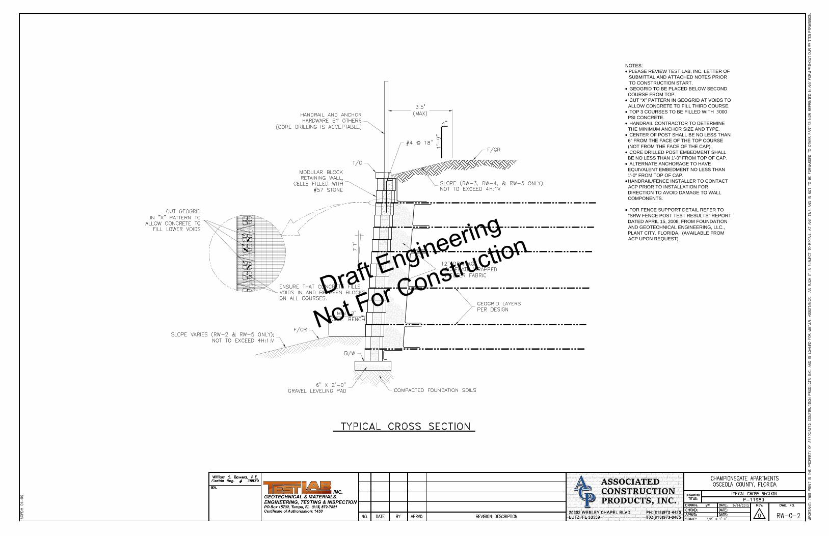
3.6. At locations where a utility structure impedes geogrid placement, the geogrid must be wrapped up all sides of the structure by at least 12
inches. Additional geogrid layers must be added and cut as necessary to ensure the geogrid is wrapped up the structure on all sides.
AASHTO #57 stone must be placed between the SRW units and the utility structure, and the stone must be wrapped in filter fabric.
3.7. The garage structures must be constructed prior to the retaining walls. A continuous layer of filter fabric must be installed behind the
SRW blocks and along the side of the garage structure to prevent soil washout at the joint between structure and the retaining wall.
SECTION 4: CONSTRUCTION TOLERANCES
4.1 Vertical control:
± 1.25 inches over a 10-foot distance
4.2 Horizontal location control:
Straight Lines: ± 1.25 inches over a 10-foot distance
Straight and radius corner location: ± 1.0 foot
Curves and serpentine radius: ± 2.0 feet
4.3 Rotation
From established plan wall batter: 2.0°
Maximum ± 10% from total established horizontal setback
Building: 1.25 inch over a 10-foot distance
SECTION 5: FOUNDATION
5.1 The subgrade earthwork work shall be performed by the Owner or the Owner's representative and not by the wall installer.
5.2 Contractor shall verify locations of existing utilities prior to excavation.
5.3 In the event that the groundwater table is encountered during excavation, the foundation area shall be dewatered to a depth of two feet
below the excavation prior to foundation construction.
5.4 The contractor shall excavate to a level of two feet beneath the bottom of the leveling pad. The excavation shall extend outward and
downward on a 1 horizontal: 2 vertical slope from the bottom outside edge of the leveling pad.
5.5 In the event that unsuitable material (clay, organic soils and/or muck/peat) is encountered during the installation of the wall, all
unsuitable material encountered shall be excavated to a depth required for complete removal and replaced with suitable material as
specified in Section 2.4. The foundation soil shall be compacted to a depth of 24 inches to minimum of 95% of the modified Proctor
maximum dry density (ASTM D-1557).
5.6 The prepared surface shall meet or exceed an allowable bearing capacity of 2,000 psf as verified by the geotechnical engineer prior to
start of leveling pad construction.
SECTION 6: LEVELING PAD CONSTRUCTION
6.1. Leveling pad shall be constructed as shown on the construction drawings. The aggregate leveling pad material shall be compacted to
provide a firm, level bearing surface on which to place the first course of units. The leveling pad shall be wrapped in filter fabric at all
pond applications.
SECTION 7: SEGMENTAL RETAINING WALL (SRW) UNIT INSTALLATION
7.1. All walls shall be installed in accordance with local building codes and requirements. SRW units shall be installed at the proper elevation
and orientation as shown on specifications and construction drawings of this submittal and in accordance with the manufacturer's
recommendations. The specifications and construction drawings shall govern in there is any conflict between the drawings produced
and the manufactures' recommendations.
7.2. The base course of SRW units shall be leveled side-to-side, front-to-rear and with adjacent units, and aligned to ensure full contact with
the leveling pad. The base course is the most important to ensure accurate and acceptable results. No gaps shall be left between the
front of adjacent units. All units shall be checked for level and alignment as they are placed. Place shims as required to maintain design
batter. Proper care shall be taken to develop straight lines and smooth curves on base course as per wall layout.
7.3. The backfill in front and back of entire base row shall be placed and compacted to firmly lock them in place. All excess debris shall be
cleaned from top of units.
7.4. Install next course of wall units on top of base row. Position blocks to be offset from seams of blocks below. Blocks shall be placed fully
forward so knob and groove are engaged. Check each block for proper alignment and level. Backfill behind block with drainage
aggregate to width shown on the construction drawings. Install each subsequent course in like manner. Repeat procedure to the extent
of wall height.
7.5. All wall facing cap units shall be properly aligned to underlying SRW units and affixed using an exterior-grade, flexible, high-strength
concrete adhesive. Rigid adhesive or mortar are not acceptable.
SECTION 8: GEOSYNTHETIC REINFORCEMENT PLACMENT
8.1 All geosynthetic reinforcement shall be installed at the proper elevation and orientation as shown on the construction drawings.
8.2 The geosynthetic soil reinforcement shall be laid horizontally on top of the SRW units and horizontally on compacted backfill.
8.3 Embedment of the geosynthetic in the SRW units shall be consistent with SRW manufacturer's recommendations. Correct orientation of
the geosynthetic reinforcement shall be verified by the contractor to be in accordance with the geosynthetic manufacturer's
recommendations. The highest strength direction of the geosynthetic must be perpendicular to the wall face.
8.4 Geosynthetic reinforcement layers shall be one continuous piece for their entire embedment length. Splicing of the geosynthetic in the
design strength direction (perpendicular to the wall face) shall not be permitted. Along the length of the wall, horizontally adjacent
sections of geosynthetic reinforcement shall be butted in a manner to ensure 100 percent coverage parallel to the wall face.
8.5 Tracked construction equipment shall not be operated directly on the geosynthetic reinforcement. A minimum of 6 inches of backfill is
required prior to operation of tracked vehicles over the geosynthetic. Turning should be kept to a minimum. Rubber-tired equipment
may pass over the geosynthetic reinforcement at slow speeds (less than 10 mph).
8.6 The geosynthetic reinforcement shall be free of wrinkles prior to placement of infill soil. The nominal tension shall be applied to the
reinforcement and secured in place with staples, stakes, or by hand tensioning until the geosynthetic reinforcement is covered by six (6)
inches of fill.
SECTION 9: DRAINAGE AGGREGATE
9.1 Drainage aggregate shall be installed to the line, grades, and sections shown on the construction drawings. Drainage aggregate shall
be placed to the minimum thickness shown on the construction drawings between and behind units.
SECTION 10: REINFORCED (INFILL) SOIL
10.1.The reinforced (infill) soil shall be placed as shown in the construction drawings in lifts not to exceed 8 inches in thickness and be
compacted to 95% of the modified proctor maximum dry density (ASTM D-1557).
10.2.Testing shall be the responsibility of the Owner. Density tests shall be performed on each lift of fill and not exceeding one hundred
(100) linear feet along the wall each day.
10.3.Filter fabric shall be placed between the drainage aggregate behind the wall and the infill soil.
10.4.Only hand-operated compaction equipment shall be allowed within five (5) feet of the back surface of the SRW units. No heavy
construction equipment shall be allowed within five (5) feet of the back surface of the SRW units.
10.5.Backfill shall be placed from the SRW wall units rearward into the embankment to ensure that the geosynthetic reinforcement remains
taut. The backfill shall be placed and spread in such a manner as to eliminate wrinkles or movement of the geosynthetic reinforcement
and the SRW units.
10.6.Track mounted construction equipment shall not be operated directly on the geosynthetic reinforcement. A minimum backfill thickness
of six (6) inches is required prior to the operation of track-mounted vehicles over the geosynthetic reinforcement. Turning of
track-mounted vehicles should be kept to a minimum to prevent tracks from displacing the fill and damaging the geosynthetic
reinforcement.
10.7.Rubber tired equipment may pass over the geosynthetic reinforcement at speeds less than ten (10) miles per hour. Sudden braking
and sharp turning shall be avoided.
10.8.At the end of each day's operation, the Contractor shall slope the last level of backfill away from the wall facing and reinforced backfill
to direct water runoff away from the wall face.
10.9.At completion of wall construction, backfill shall be placed level with final top of wall elevation. If final grading, paving, landscaping,
and/or storm drainage installation adjacent to the wall is not placed immediately after wall completion, temporary grading and drainage
shall be provided to ensure water runoff is not directed at the wall nor allowed to collect or pond behind the wall until final construction
adjacent to the wall is completed.
SECTION 11: CONSTRUCTION ADJACENT TO COMPLETED WALL
11.1.The Owner is responsible for ensuring that construction by others adjacent to the wall does not disturb the wall or place temporary
construction loads on the wall that exceed design loads, including loads such as water pressure, temporary grades, or equipment
loading. Heavy paving or grading equipment shall be kept a minimum of three feet behind the back of the wall face. Care should be
taken to ensure water runoff is directed away from the wall structure until final grading and surface drainage collection systems are
completed. Any gutter downspout(s) from nearby buildings must be oriented such that water discharged from the downspout(s) is
directed away from the retaining wall.
11.2.Contact wall installer prior to planting any landscaping adjacent to wall to avoid damage to the geosynthetic reinforcement.
SECTION 12: MAINTENANCE
12.1 The Owner is responsible for maintenance of the wall and its components throughout the life of the wall.
12.2 The Owner must ensure that the design embedment height is maintained at the toe of the wall, and that the ground is adequately
sodded and/or paved above and below the wall to prevent scour/erosion of the soils.
12.3 The outlet pipes must be regularly inspected and cleared of vegetation growth, soil build-up, and other obstructions that could
potentially impede adequate drainage.
12.4 The Owner is to ensure growth of woody vegetation and/or vegetation with an expansive root system does not impair the wall,
including beneath the wall and in the zone of reinforced (infill) soil.
Draft Engineering
Not For Construction
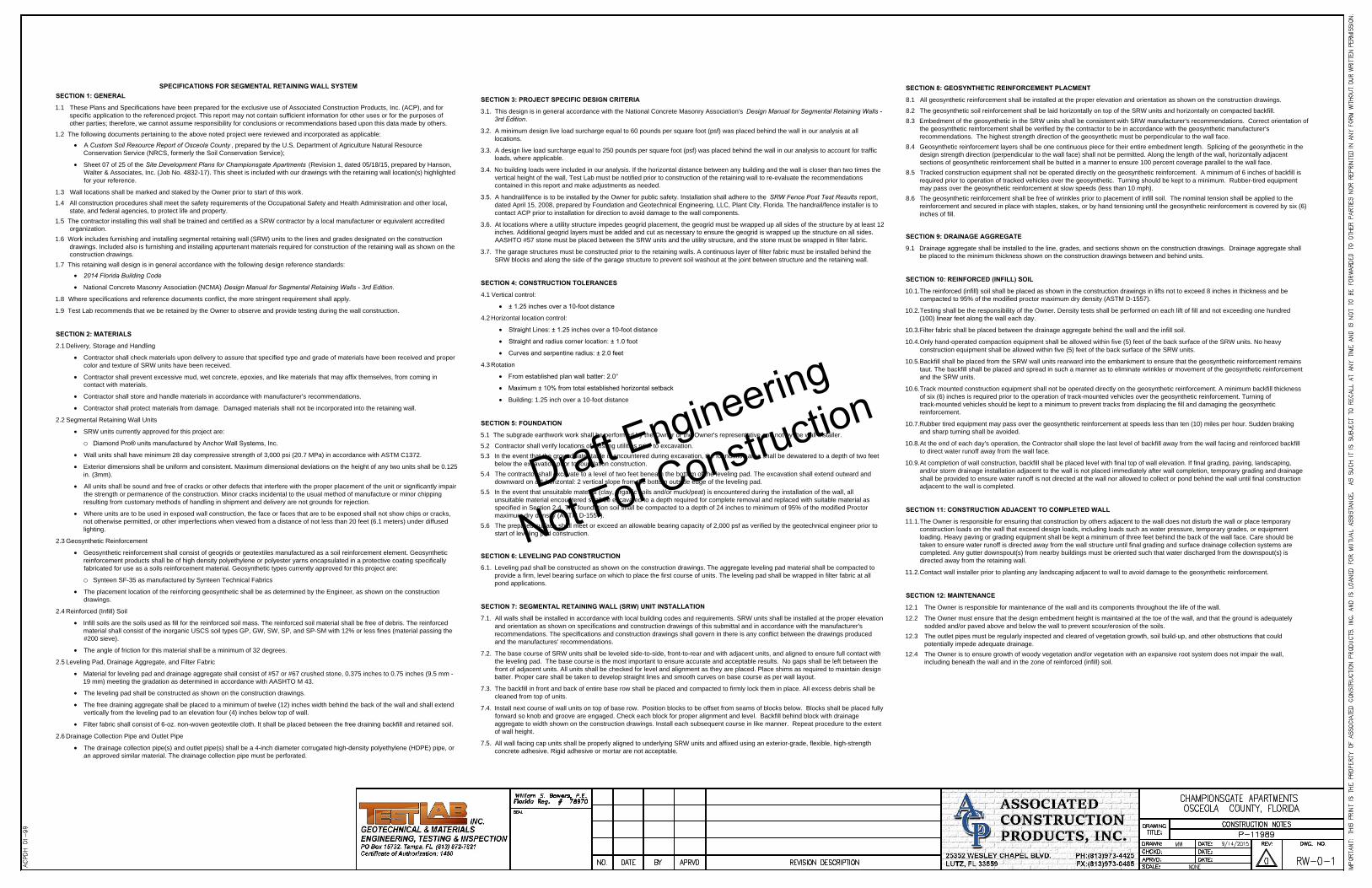
NOTES:
PLEASE REVIEW TEST LAB, INC. LETTER OF
SUBMITTAL AND ATTACHED NOTES PRIOR
TO CONSTRUCTION START.
GEOGRID TO BE PLACED BELOW SECOND
COURSE FROM TOP.
CUT “X” PATTERN IN GEOGRID AT VOIDS TO
ALLOW CONCRETE TO FILL THIRD COURSE.
TOP 3 COURSES TO BE FILLED WITH 000
PSI CONCRETE.
HANDRAIL CONTRACTOR TO DETERMINE
THE MINIMUM ANCHOR SIZE AND TYPE.
CENTER OF POST SHALL BE NO LESS THAN
6” FROM THE FACE OF THE TOP COURSE
(NOT FROM THE FACE OF THE CAP).
CORE DRILLED POST EMBEDMENT SHALL
BE NO LESS THAN 1'-0" FROM TOP OF CAP.
ALTERNATE ANCHORAGE TO HAVE
EQUIVALENT EMBEDMENT NO LESS THAN
1'-0" FROM TOP OF CAP.
HANDRAIL/FENCE INSTALLER TO CONTACT
ACP PRIOR TO INSTALLATION FOR
DIRECTION TO AVOID DAMAGE TO WALL
COMPONENTS.
FOR FENCE SUPPORT DETAIL REFER TO
"SRW FENCE POST TEST RESULTS" REPORT
DATED APRIL 15, 2008, FROM FOUNDATION
AND GEOTECHNICAL ENGINEERING, LLC.,
PLANT CITY, FLORIDA. (AVAILABLE FROM
ACP UPON REQUEST)
Draft Engineering
Not For Construction
NOTE:
UTILITY PIPES TO BE INSTALLED CONCURRENTLY
WITH RETAINING WALL. WALL CONSTRUCTOR
MUST COORDINATE WITH UTILITY CONTRACTOR.
ADJUST PLACEMENT OF ADDITIONAL LAYERS UP
OR DOWN TO CLEAR PIPE.
Draft Engineering
Not For Construction
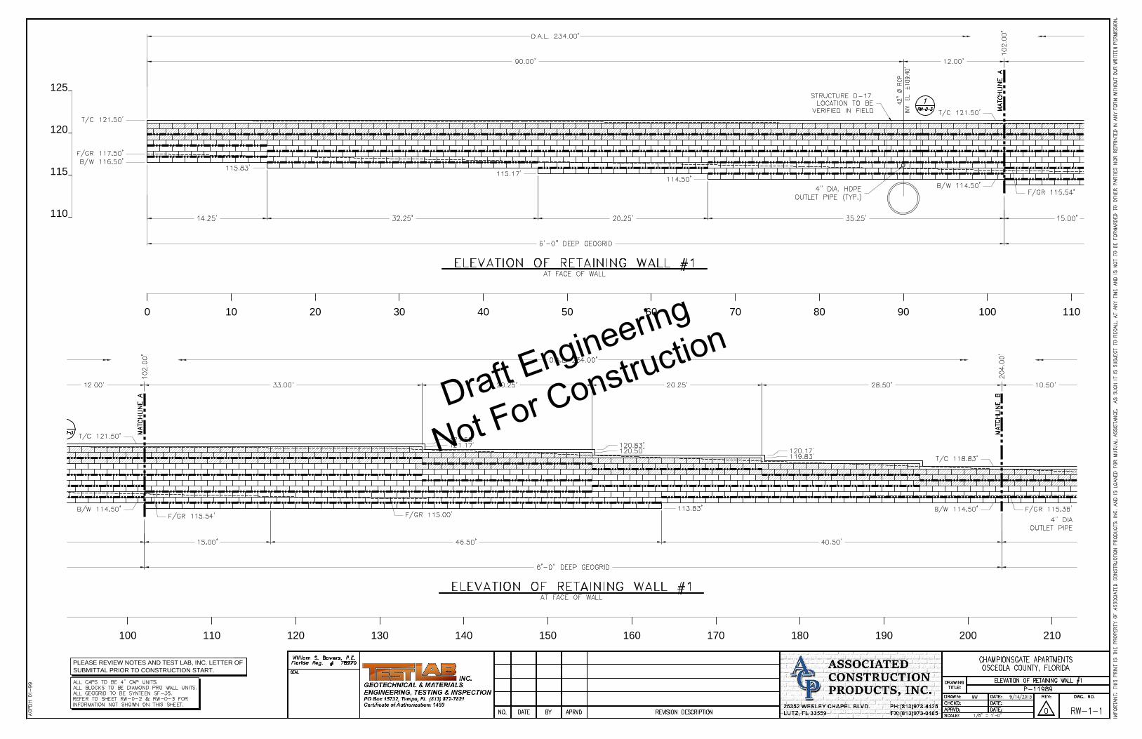
110
115
120
125
0 10 20 30 40 50 60 70 80 90 100 110
100 110 120 130 140 150 160 170 180 190 200 210
PLEASE REVIEW NOTES AND TEST LAB, INC. LETTER OF
SUBMITTAL PRIOR TO CONSTRUCTION START.
Draft Engineering
Not For Construction

200 210 220 230
PLEASE REVIEW NOTES AND TEST LAB, INC. LETTER OF
SUBMITTAL PRIOR TO CONSTRUCTION START.
Draft Engineering
Not For Construction
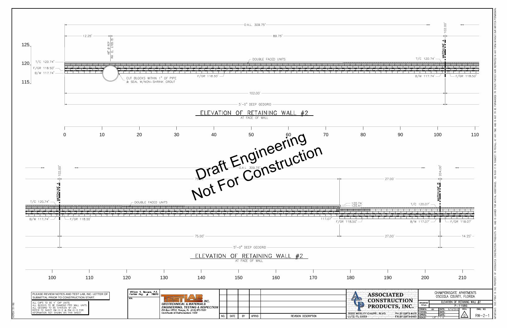
115
120
125
0 10 20 30 40 50 60 70 80 90 100 110
100 110 120 130 140 150 160 170 180 190 200 210
PLEASE REVIEW NOTES AND TEST LAB, INC. LETTER OF
SUBMITTAL PRIOR TO CONSTRUCTION START.
Draft Engineering
Not For Construction

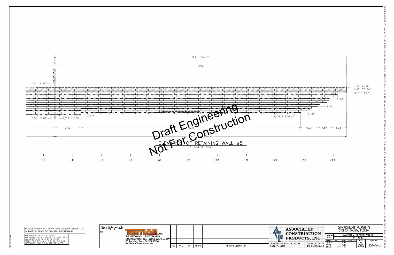
200 210 220 230 240 250 260 270 280 290 300
PLEASE REVIEW NOTES AND TEST LAB, INC. LETTER OF
SUBMITTAL PRIOR TO CONSTRUCTION START.
Draft Engineering
Not For Construction

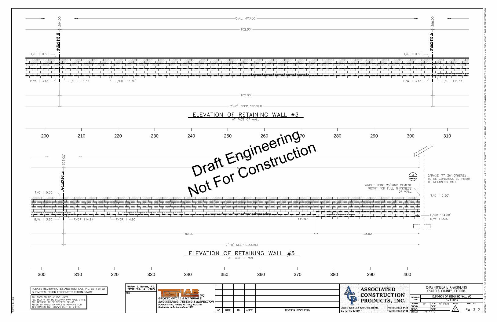
110
115
120
0 10 20 30 40 50 60 70 80 90 100 110
100 110 120 130 140 150 160 170 180 190 200 210
PLEASE REVIEW NOTES AND TEST LAB, INC. LETTER OF
SUBMITTAL PRIOR TO CONSTRUCTION START.
Draft Engineering
Not For Construction
200 210 220 230 240 250 260 270 280 290 300 310
300 310 320 330 340 350 360 370 380 390 400
PLEASE REVIEW NOTES AND TEST LAB, INC. LETTER OF
SUBMITTAL PRIOR TO CONSTRUCTION START.
Draft Engineering
Not For Construction
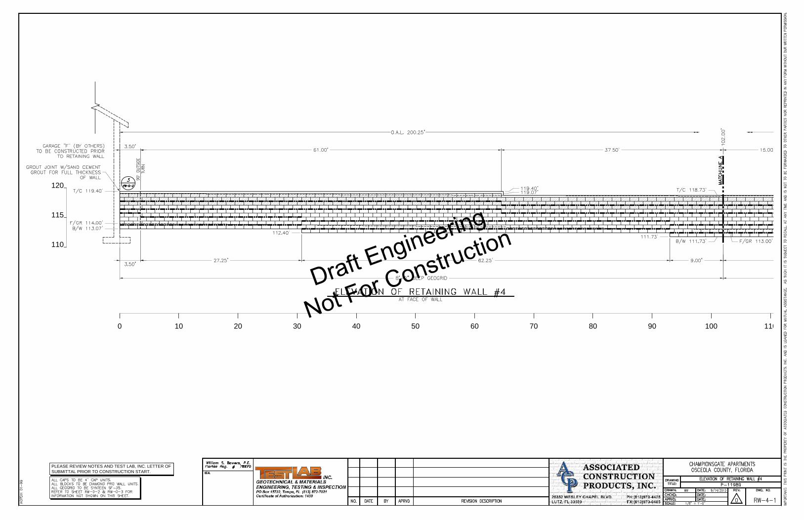
110
115
120
0 10 20 30 40 50 60 70 80 90 100 110
PLEASE REVIEW NOTES AND TEST LAB, INC. LETTER OF
SUBMITTAL PRIOR TO CONSTRUCTION START.
Draft Engineering
Not For Construction

100 110 120 130 140 150 160 170 180 190 200
PLEASE REVIEW NOTES AND TEST LAB, INC. LETTER OF
SUBMITTAL PRIOR TO CONSTRUCTION START.
Draft Engineering
Not For Construction

110
115
120
125
0 10 20 30 40 50 60 70 80 90 100 110
PLEASE REVIEW NOTES AND TEST LAB, INC. LETTER OF
SUBMITTAL PRIOR TO CONSTRUCTION START.
Draft Engineering
Not For Construction

100 110 120 130 140 150 160 170 180 190 200 210
PLEASE REVIEW NOTES AND TEST LAB, INC. LETTER OF
SUBMITTAL PRIOR TO CONSTRUCTION START.
Draft Engineering
Not For Construction
200 210 220 230 240 250 260 270 280 290 300
PLEASE REVIEW NOTES AND TEST LAB, INC. LETTER OF
SUBMITTAL PRIOR TO CONSTRUCTION START.
Draft Engineering
Not For Construction
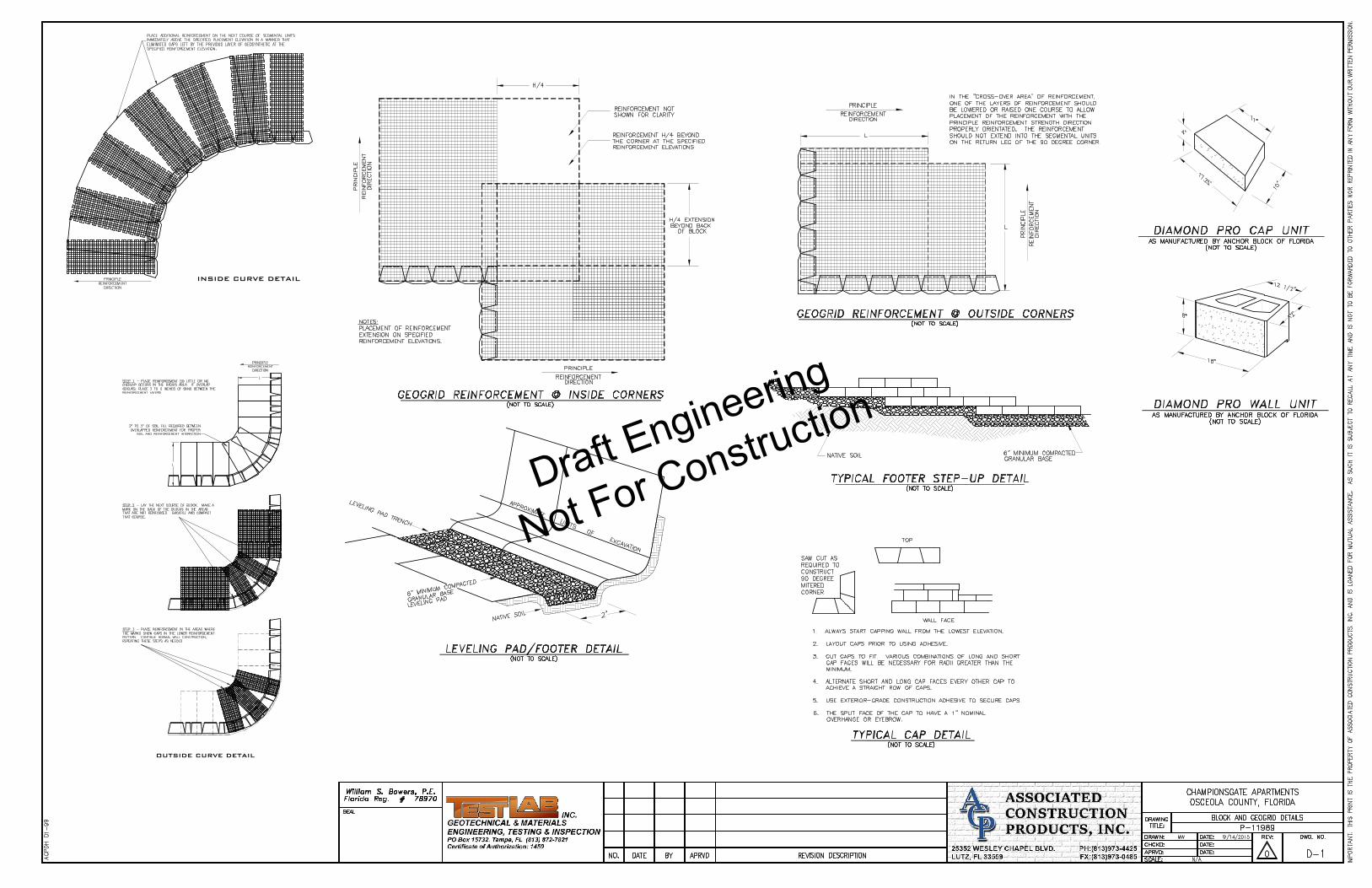
INSIDE CURVE DETAIL
OUTSIDE CURVE DETAIL
Draft Engineering
Not For Construction

Draft Engineering
Not For Construction
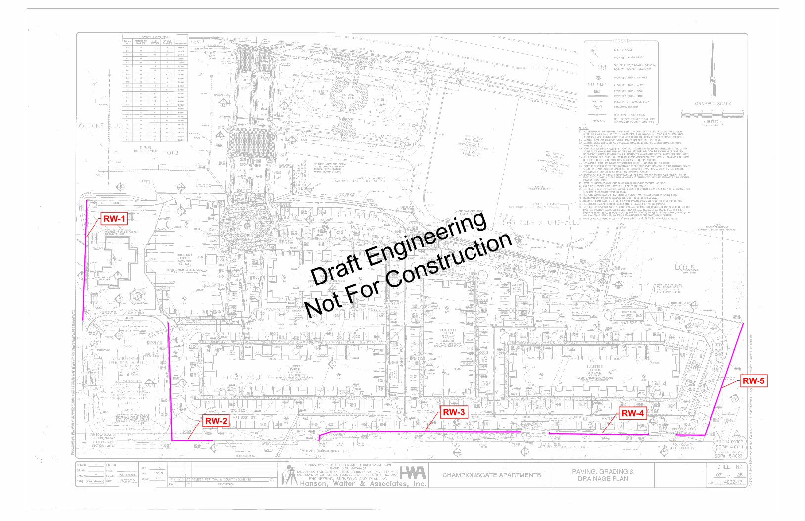
RW-1
RW-2
RW-3
RW-4
RW-5
Draft Engineering
Not For Construction
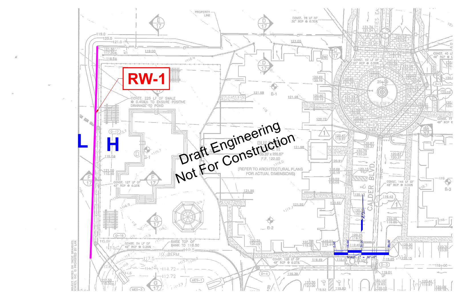
RW-1
L
H
Draft Engineering
Not For Construction

RW-2
L
H
Draft Engineering
Not For Construction
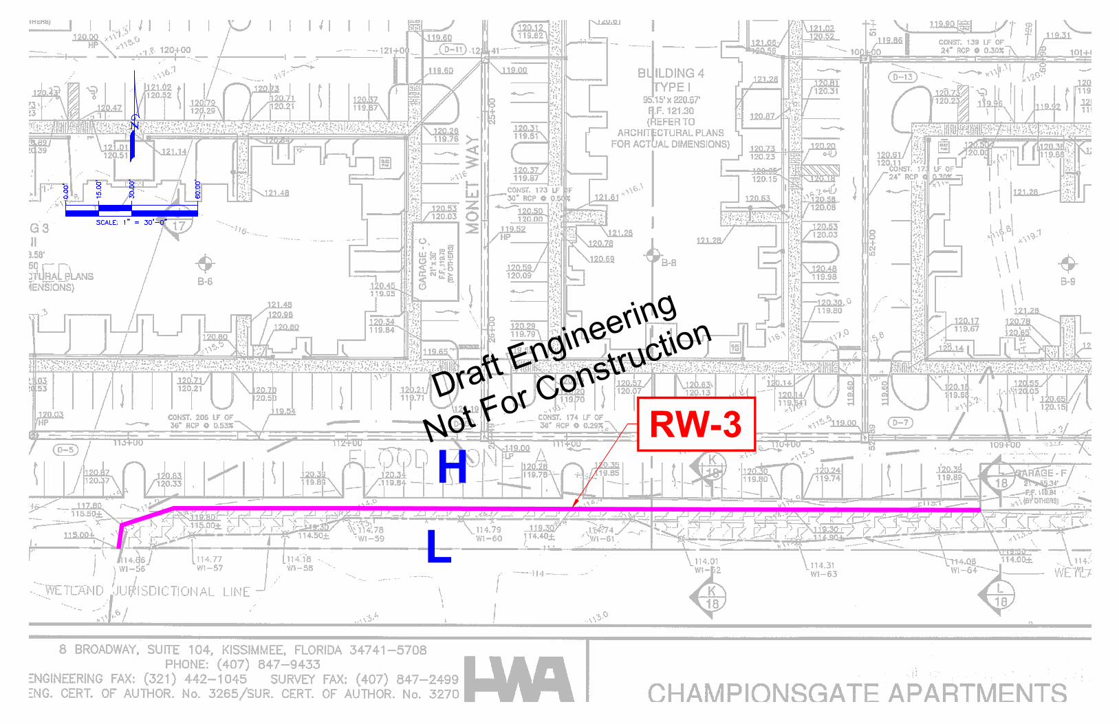
RW-3
L
H
Draft Engineering
Not For Construction

RW-4
RW-5
L
H
L
H
Draft Engineering
Not For Construction