Embed Size (px)
Citation preview

Dr. Branko Bijeljic
Dr. Ann Muggeridge
Prof. Martin Blunt
Diffusion and Dispersion in Networks
Dept. of Earth Science and Engineering,Imperial College,
London

OVERVIEW
• Introduction to Diffusion and Dispersion in Single Ducts and Porous Media
• Motivation
• Model
• Results and Discussion
• Conclusions and Further Work

MIXING of FLOWING FLUIDSin SINGLE DUCTS
- BY DIFFUSION: DUE TO RANDOM MOLECULAR MOTION
HYDRODYNAMIC DISPERSION: SPREAD OF CONC. DISTRIBUTION WIDER AT OUTPUT
- BY ADVECTION: DUE TO NON-UNIFORM VELOCITY FIELD
MOLECULAR DIFFUSION
A)
B)
t = 0 t = tfinal adv.onlyadv.+diff.
MIXING of FLOWING FLUIDS in POROUS MEDIA
Pore scale diffusion processes are COMPLEX:
What is the correct macroscopic description?

MOTIVATION
Describe macroscopic dispersion using particle tracking pore network model.
• Oil reservoirs:
• Tracers
• Development of gas/oil miscibility
• Aquifers
• Contaminant transfer

Network Modelling of Diffusion and Dispersion
Model tracer flow initially:1. Calculate mean velocity in each pore throat
using existing network simulator2. Use analytic solution to determine velocity
profile in each pore throat3. In each time step particles move by
a. Advectionb. Diffusion (random walk)
4. Impose rules for mixing at junctions5. Obtain DL and DT
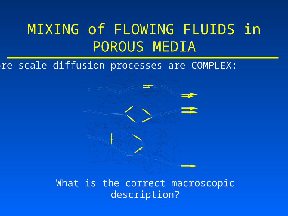
Unit Cell in Network Modelling of Diffusion and Dispersion
?
?
?Advection Diffusion
?
B. C. in throats- advection: no-slip velocity- diffusion: angle of incidence = angle of reflection

RULES FOR MIXING at JUNCTIONS-
Mixing ~ geometry, discharge pattern, conc. distributions
Previous work:(e.g. Sahimi et al., Chem. Eng. Sci. , 1986; Berkowitz et al.,
Water Resour. Res., 1994; Park and Lee, Water Resour. Res., 1999) a) stream tube routing b) complete mixing
Diffusio n
Flow
Pe >>1 Pe<<1

RULES FOR MIXING at JUNCTIONS-OUR STUDY
a) Particle leaves the junction in diffusive step:- area weighted rule ~ Ai / Ai ;- assign a new site at random; - forwards (outgoing) and backwards allowed
b) Particle leaves the junction in advective step:
- flowrate weighted rule ~ Fi / Fi ;- assign a new site at random and move by udt;- only forwards (outgoing) allowed

CURRENT WORK
• Verify the particle-tracking advection/random walk in single ducts
• cf. Taylor-Aris analytical solutions
• Implement and test junction rules
• cf. experimental data from literature

ANALYSIS of DISPERSION by the PTRW MODEL
Pe = 10N = 5024 r = 50 mDm= 1.0 ·10-10 m2/sDL= 3.1 ·10-10 m2/s
-60
-50
-40
-30
-20
-10
0
-60 -50 -40 -30 -20 -10 0
Y-DISTANCE from CENTRE (micron)
Z-D
IST
AN
CE
fro
m C
EN
TR
E (
mic
ron
)X
0
500
1000
1500
2000
2500
0 1000 2000 3000 4000 5000 6000
particle label
X d
isp
lace
men
t(m
icro
n)
t = 0s t = 60s
0
200
400
600
800
1000
1200
-1500 -1000 -500 0 500 1000 1500
displacement(micron)
Nu
mb
er o
f p
arti
cles
model
analytical

RESULTS (1) Longitudinal Dispersion in a duct with
circular cross section: TA vs. model
TA: DL/Dm=1+(Pe2); -shape factor
0
10
20
30
40
50
60
0 10 20 30 40 50 60
Pe=u*h/Dm
DL
/Dm
model analytical
y = 0.0208x + 1.0015
R2 = 1
0
10
20
30
40
50
60
0 500 1000 1500 2000 2500 3000
Pe^2
DL
/Dm
model Linear (model)
= 0.0208 = 1/48

RESULTS (2) Longitudinal Dispersion between two
infinitely long parallel plates: TA vs. model
TA: DL/Dm=1+(Pe2); = 0.0190=2/105
0
10
20
30
40
50
60
0 10 20 30 40 50 60
Pe=u*h/D
DL
/Dm
analytical model
y = 0.019x + 1.0038
R2 = 1
0
5
10
15
20
25
30
35
0 500 1000 1500 2000
Pe^2
DL
/Dm
model Linear (model)

RESULTS (3) Longitudinal Dispersion in a duct with square
cross section: model
DL/Dm=1+(Pe2); = 0.0342
0
10
20
30
40
50
60
70
80
90
100
0 10 20 30 40 50 60
Pe=u*h/Dm
DL
/Dm
y = 0.0342x + 1.0032
R2 = 0.9999
0
10
20
30
40
50
60
70
80
90
100
0 500 1000 1500 2000 2500 3000
Pe^2=(u*h/Dm)^2
DL
/Dm
square duct Linear (square duct)

RESULTS(1-3) – CONCLUSIONS
DL - longitudinal dispersion coefficient (asymptotic)
Cross section
DL/Dm=1+(Pe2)
Parallel plates 0.190
Circular 0.208
Square 0.342
Dm - molecular diffusion coefficient
Pe – Peclet number ; - shape factor
Conclusion: longitudinal dispersion increases with greater wall friction

• New pore-scale model to describe dispersion in 2D networks at pore scale
• Compare results with 2D square networks of Bernabe and Bruderer (Water Resour. Res., 2001) – flow orientation important
• Compare results with experimental data for dispersion in beadpacks, unconsolidated sandpacks and sandstones
FUTURE WORK – short term

EXPERIMENTAL DISPERSION IN SANDPACKS
(Fried&Combarnous, Adv. Hydrosc.,1971)
PeFD
D
D
Dregimediffusion
m
T
m
L 3.0;1
:)1
53.0;:)2 PePeD
Dregimetransition
m
L
510300;:)4 PePeD
Ddispersionmechanical
m
L
510;,,:)5 PeRePeD
D
D
Ddispersionturbulent
m
T
m
L
9.0,05.001.0;1
2.1,5.0;1
3005:)3
TTTm
T
LLLm
L
T
L
PeFD
D
PeFD
D
Pedispersionlayerboundary
DL/Dm
DT/Dm
I)
II)
III)
IV)
V)
22,: PePeD
D
D
Ddispersionholdup
m
T
m
L

• Investigate influence of network properties on longitudinal and transverse dispersion coefficients
• Extension of the model to
• two-phase flow
• M > 1 / miscible gas displacements
FUTURE WORK – long term


![Branko [2005]- Performative Architecture - Beyond_Instrumentality](https://img.pdfslide.us/doc/110x75/55343bd55503469d708b4a44/branko-2005-performative-architecture-beyondinstrumentality.jpg)