Embed Size (px)
Citation preview
Industrial Embedded Systems
- Design for Harsh Environment -
Dr. Alexander Walsch
Part VI
WS 2011/12
Technical University Munich (TUM)
Agenda
Today:
Architecture – High Level Design (Software)
Recap:
− Architecture – High Level Design (Hardware)
Slide2A. Walsch, IN2244
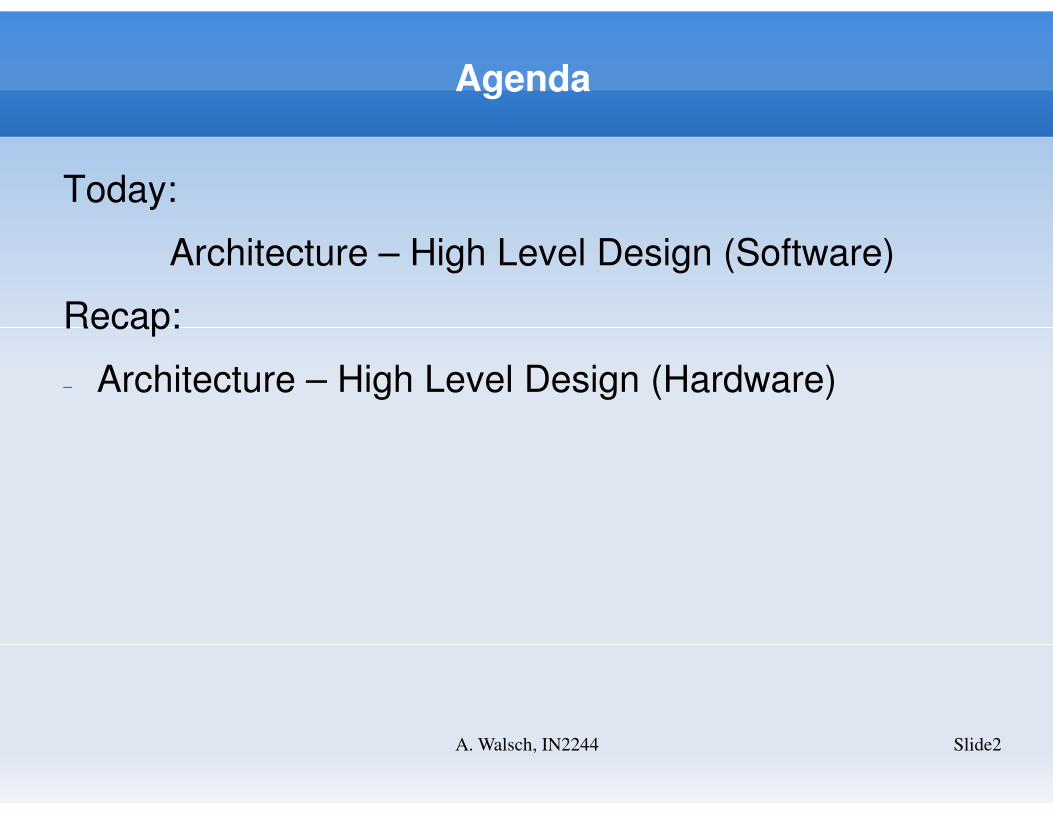
V-Model
Slide3A. Walsch, IN2244
Approach - Recap
Slide4A. Walsch, IN2244
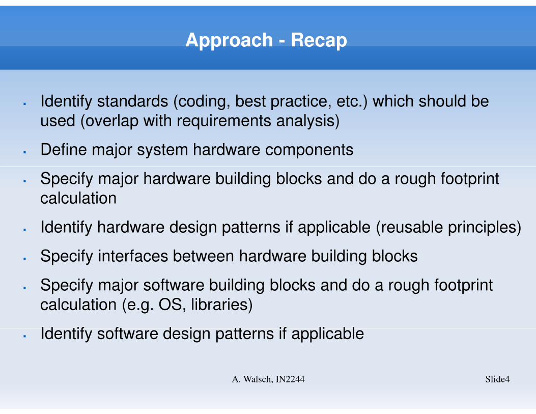
� Identify standards (coding, best practice, etc.) which should be
used (overlap with requirements analysis)
� Define major system hardware components
� Specify major hardware building blocks and do a rough footprint
calculation
� Identify hardware design patterns if applicable (reusable principles)
� Specify interfaces between hardware building blocks
� Specify major software building blocks and do a rough footprint
calculation (e.g. OS, libraries)
� Identify software design patterns if applicable
First Steps
Slide5A. Walsch, IN2244
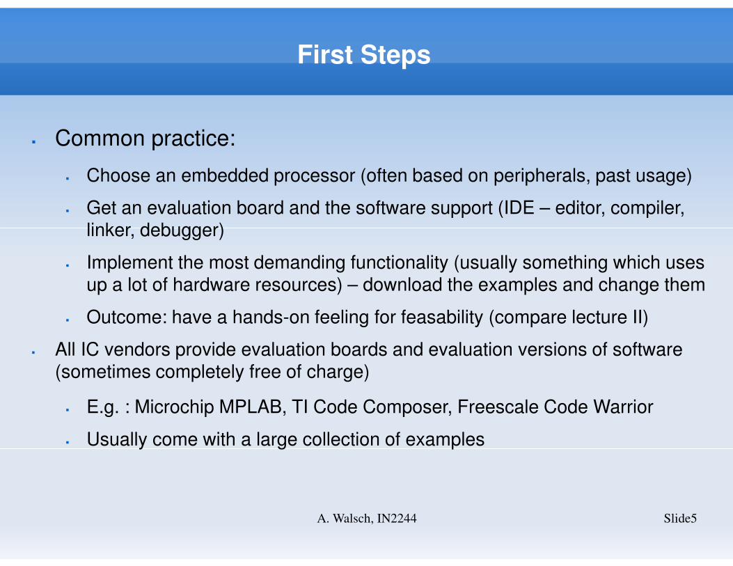
� Common practice:
� Choose an embedded processor (often based on peripherals, past usage)
� Get an evaluation board and the software support (IDE – editor, compiler, linker, debugger)
� Implement the most demanding functionality (usually something which uses up a lot of hardware resources) – download the examples and change them
� Outcome: have a hands-on feeling for feasability (compare lecture II)
� All IC vendors provide evaluation boards and evaluation versions of software (sometimes completely free of charge)
� E.g. : Microchip MPLAB, TI Code Composer, Freescale Code Warrior
� Usually come with a large collection of examples
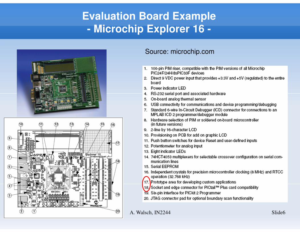
Evaluation Board Example
- Microchip Explorer 16 -
Slide6A. Walsch, IN2244
Source: microchip.com
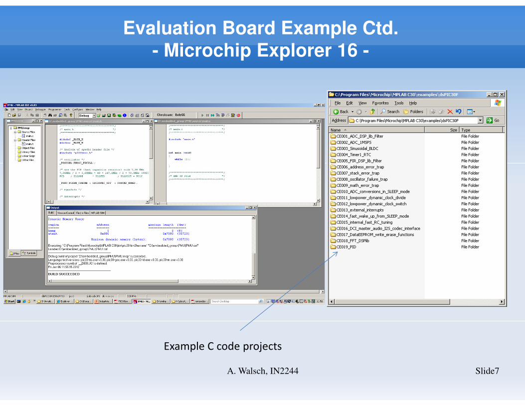
Evaluation Board Example Ctd.
- Microchip Explorer 16 -
Slide7A. Walsch, IN2244
Example C code projects
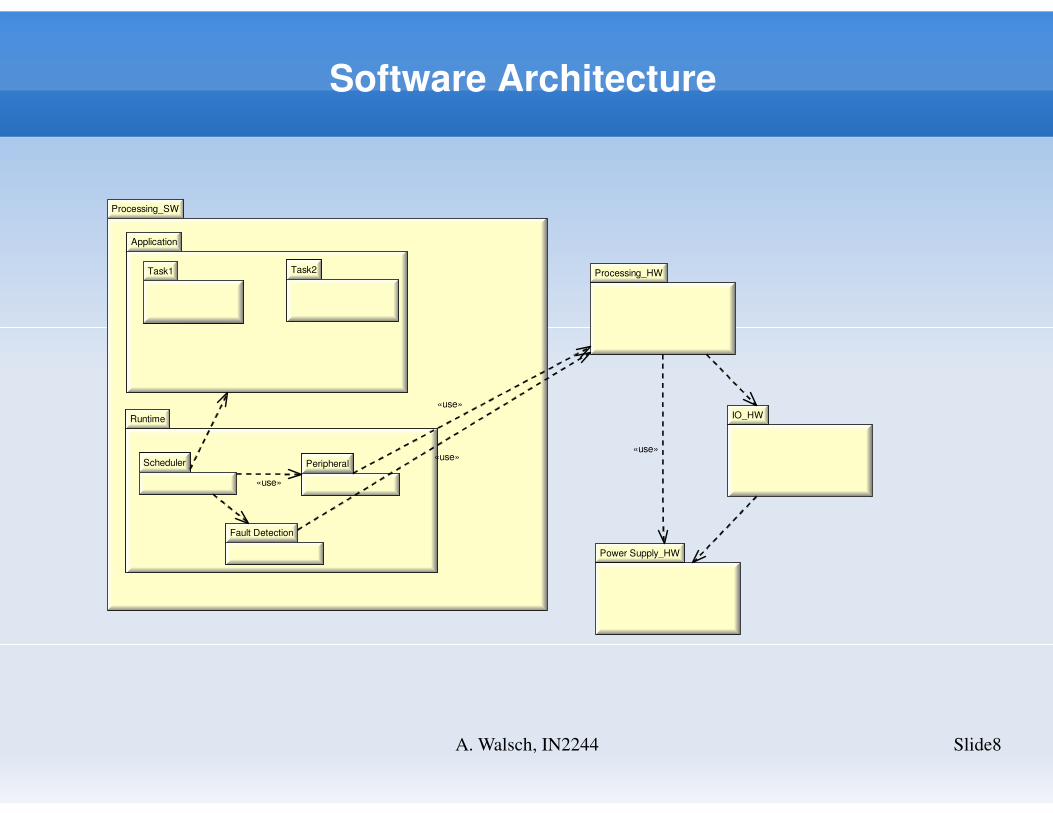
Software Architecture
Slide8A. Walsch, IN2244
Processing_SW
Application
Task1 Task2
Runtime
Fault Detection
PeripheralScheduler
Application
Task1 Task2Task1 Task2
Runtime
Fault Detection
PeripheralScheduler
Fault Detection
PeripheralScheduler
Processing_HW
IO_HW
Power Supply_HW
«use»
«use»
«use»«use»
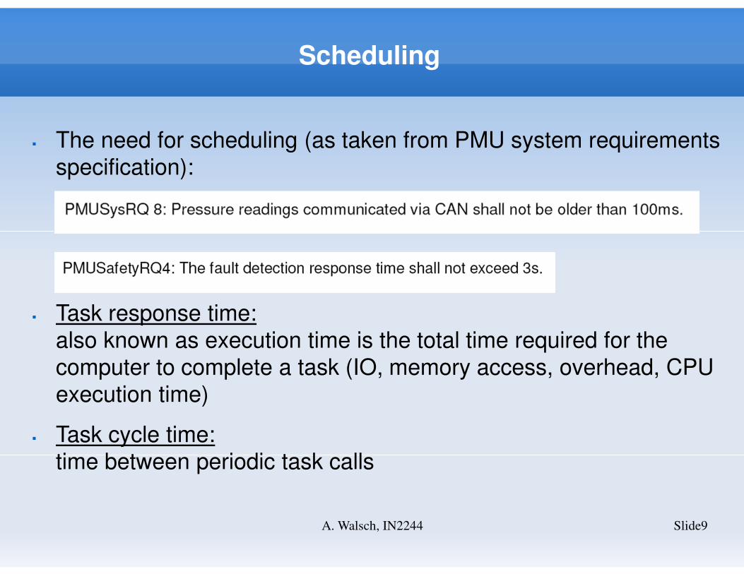
Scheduling
Slide9A. Walsch, IN2244
� The need for scheduling (as taken from PMU system requirements
specification):
� Task response time:
also known as execution time is the total time required for the
computer to complete a task (IO, memory access, overhead, CPU
execution time)
� Task cycle time:
time between periodic task calls
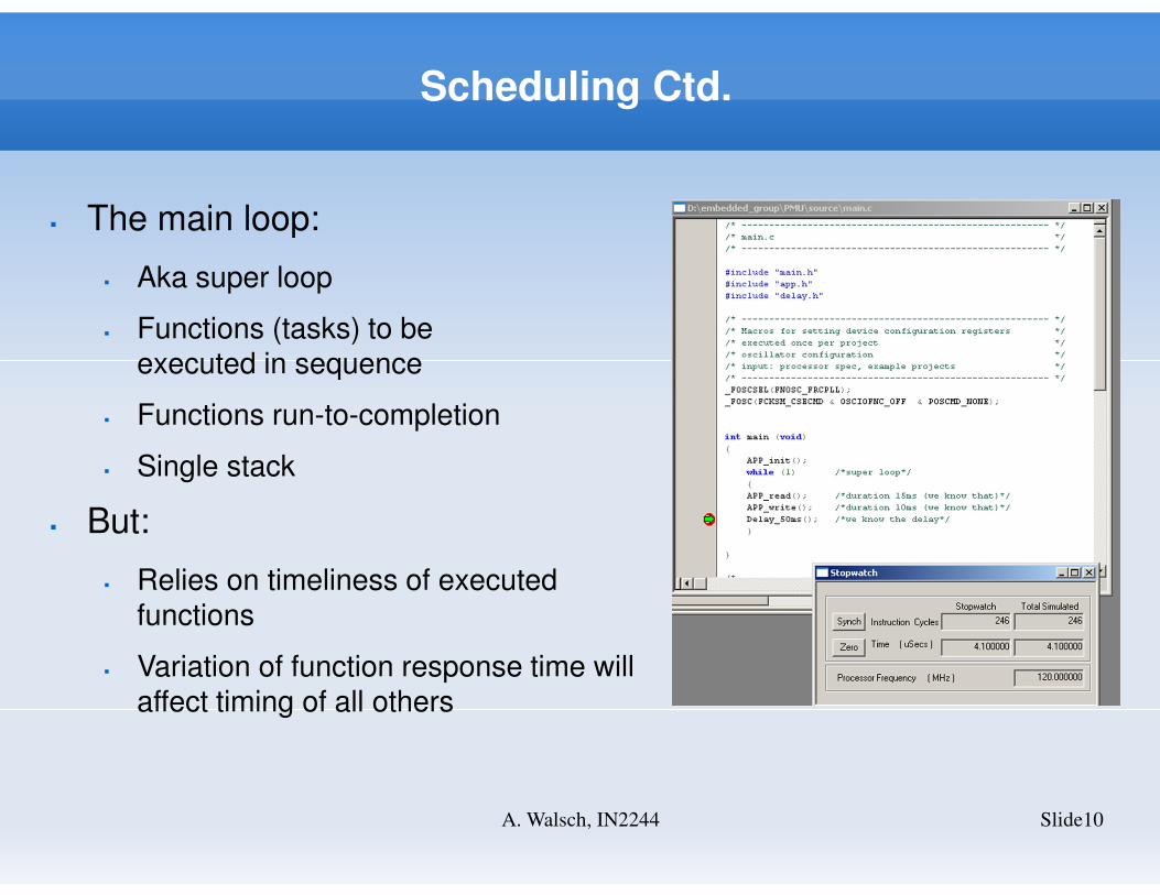
Scheduling Ctd.
Slide10A. Walsch, IN2244
� The main loop:
� Aka super loop
� Functions (tasks) to be executed in sequence
� Functions run-to-completion
� Single stack
� But:
� Relies on timeliness of executedfunctions
� Variation of function response time willaffect timing of all others
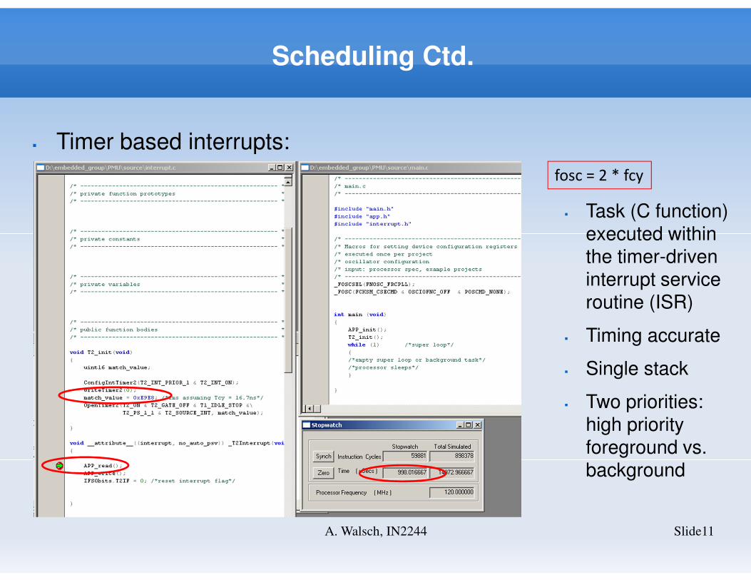
Scheduling Ctd.
Slide11A. Walsch, IN2244
� Timer based interrupts:
fosc = 2 * fcy
� Task (C function) executed within the timer-driven interrupt service routine (ISR)
� Timing accurate
� Single stack
� Two priorities: high priority foreground vs. background

Scheduling Ctd.
Slide12A. Walsch, IN2244
� Context switch
� Switch from one process to another (P1 to P2)
� Store P1 context (stack pointer if it is a multi-stack implementation, program counter, registers) – if we switch stacks we need assemby language
� Restore P2 context
� Is there a „natural“ context switch?
� If we work on one stack there is: function and interrupt calls save context automatically (the compiler does that for us):
call instruction (taken from microchip.com)
Scheduling Ctd.
Slide13A. Walsch, IN2244
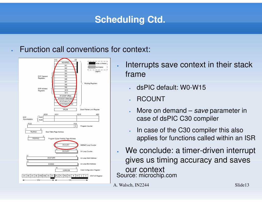
� Function call conventions for context:
� Interrupts save context in their stack
frame
� dsPIC default: W0-W15
� RCOUNT
� More on demand – save parameter in case of dsPIC C30 compiler
� In case of the C30 compiler this also applies for functions called within an ISR
� We conclude: a timer-driven interrupt
gives us timing accuracy and saves
our contextSource: microchip.com
Scheduling Ctd.
Slide14A. Walsch, IN2244
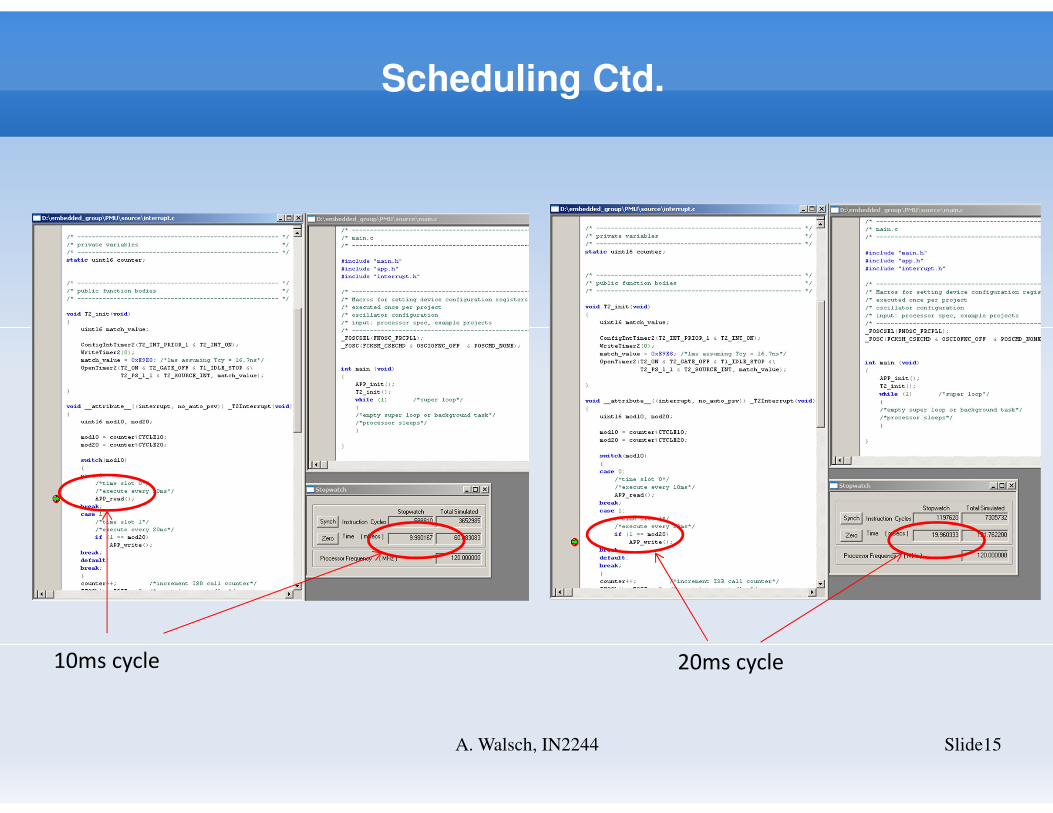
� We can use an ISR to realize a light-weight scheduler:
� We can call different functions at different times (round-robin based on elapsed time to realize different cycle times)
� All tasks are C functions that run to completion
� We can put a background task into the while(1){...} loop in main. E.g. serial communication
� BUT: does not really work well if we do have different asynchronous sources of interrupt (e.g. timer and ADC)
� Why do we use our own scheduler at all?
� Cost of commercial OS
� Lack of certificate (if we need to certify we need to show that the OS meets the criteria of the certification)
� Therefore, a very simple scheduler might be a good alternative
Scheduling Ctd.
Slide15A. Walsch, IN2244
10ms cycle 20ms cycle
Scheduling Ctd.
Slide16A. Walsch, IN2244
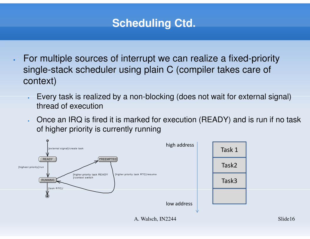
� For multiple sources of interrupt we can realize a fixed-priority
single-stack scheduler using plain C (compiler takes care of
context)
� Every task is realized by a non-blocking (does not wait for external signal) thread of execution
� Once an IRQ is fired it is marked for execution (READY) and is run if no task of higher priority is currently running
READY PREEMPTED
RUNNING
[ex te rna l s igna l] /c rea te t as k
[h ighes t p rio rit y ] /run
[ ta s k R TC ] /
[higher priority tas k RE A DY
]/c ontex t s witc h
[h igher prio rity tas k R TC] /res um e
Task3
Task2
Task 1high address
low address
Scheduling Ctd.
Slide17A. Walsch, IN2244
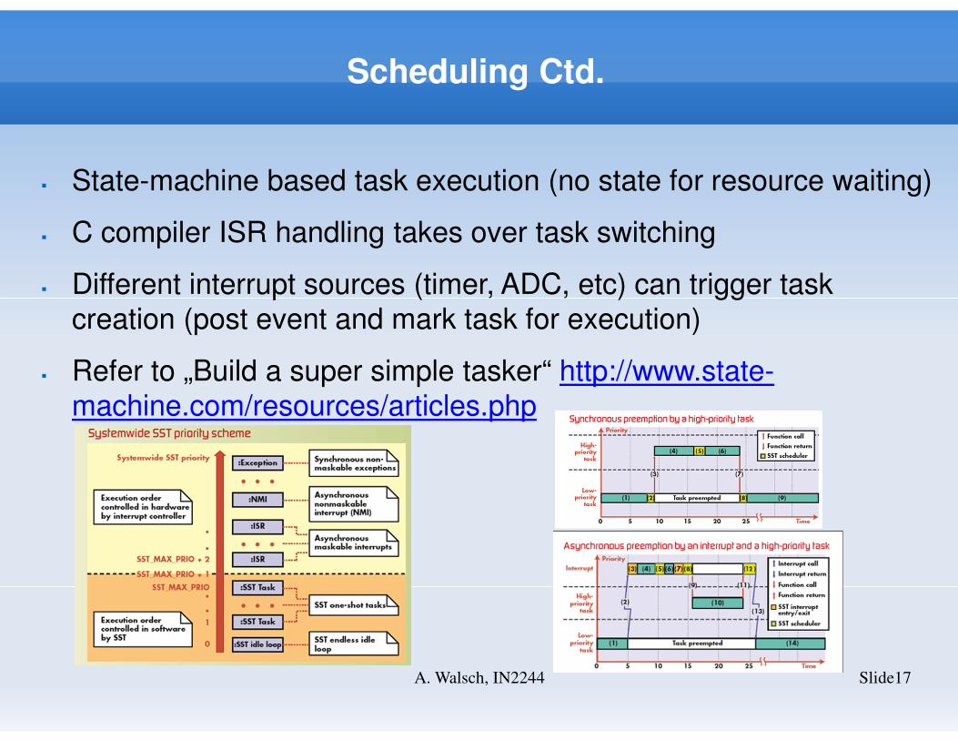
� State-machine based task execution (no state for resource waiting)
� C compiler ISR handling takes over task switching
� Different interrupt sources (timer, ADC, etc) can trigger task
creation (post event and mark task for execution)
� Refer to „Build a super simple tasker“ http://www.state-
machine.com/resources/articles.php
Peripherals
Slide18A. Walsch, IN2244
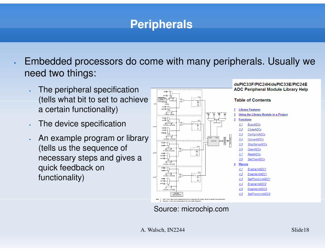
� Embedded processors do come with many peripherals. Usually we
need two things:
� The peripheral specification(tells what bit to set to achievea certain functionality)
� The device specification
� An example program or library(tells us the sequence ofnecessary steps and gives aquick feedback onfunctionality)
Source: microchip.com
Peripherals Ctd.
Slide19A. Walsch, IN2244
� It might also be a good idea to define wrapper function to
� Abstract the hardware – useful when working with different embedded processors
� Allow unified error handling
� Common functions: OpenPeripheral(), ClosePeripheral(),
ReadPeripheral(), WritePeripheral(),...
� Macros: EnableInterrupt, DisableInterrupt,...
� In case of the dsPIC Microchip provides ready-to-use functions for
peripherals, watchdog, and reset (other IC vendors do as well).
Fault Detection
Slide20A. Walsch, IN2244
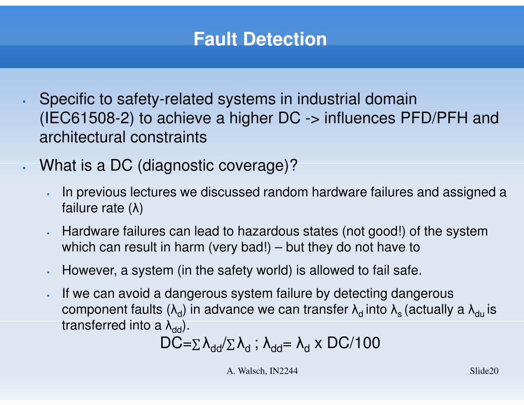
� Specific to safety-related systems in industrial domain
(IEC61508-2) to achieve a higher DC -> influences PFD/PFH and
architectural constraints
� What is a DC (diagnostic coverage)?
� In previous lectures we discussed random hardware failures and assigned a failure rate (λ)
� Hardware failures can lead to hazardous states (not good!) of the system which can result in harm (very bad!) – but they do not have to
� However, a system (in the safety world) is allowed to fail safe.
� If we can avoid a dangerous system failure by detecting dangerous component faults (λd) in advance we can transfer λd into λs (actually a λdu is transferred into a λdd).
DC=∑λdd/∑λd ; λdd= λd x DC/100
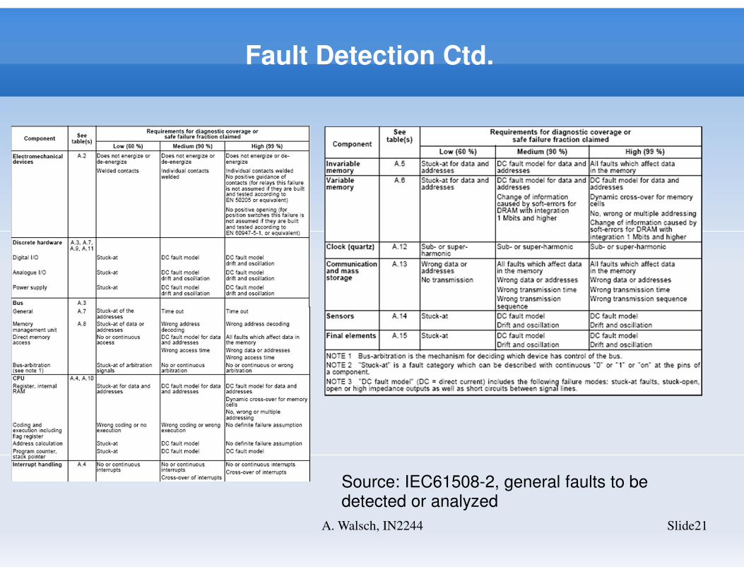
Fault Detection Ctd.
Slide21A. Walsch, IN2244
Source: IEC61508-2, general faults to be detected or analyzed
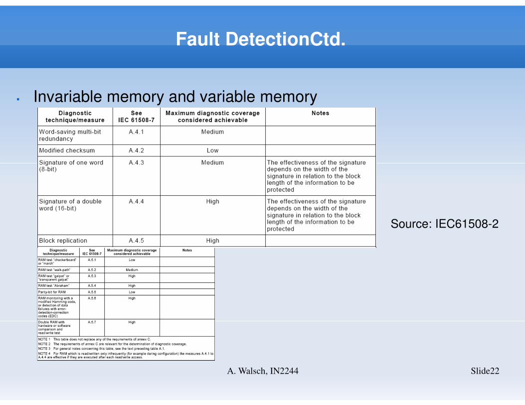
Fault DetectionCtd.
Slide22A. Walsch, IN2244
� Invariable memory and variable memory
Source: IEC61508-2
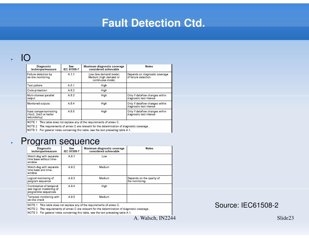
Fault Detection Ctd.
Slide23A. Walsch, IN2244
Source: IEC61508-2
� IO
� Program sequence
Fault Detection Ctd.
Slide24A. Walsch, IN2244
� Fault detection is a series of activities that happen at startup,
background (cyclic tests) and specific maintenance cycles
� CPU
� Memory (used one)
� IO
� Program sequence
� Basic tool for fault detection evaluation is FMEA
� Time-critical test is cyclic background test since it checks physical
resource during operation (must align to the fault detection
response time specified in the systems requirements)
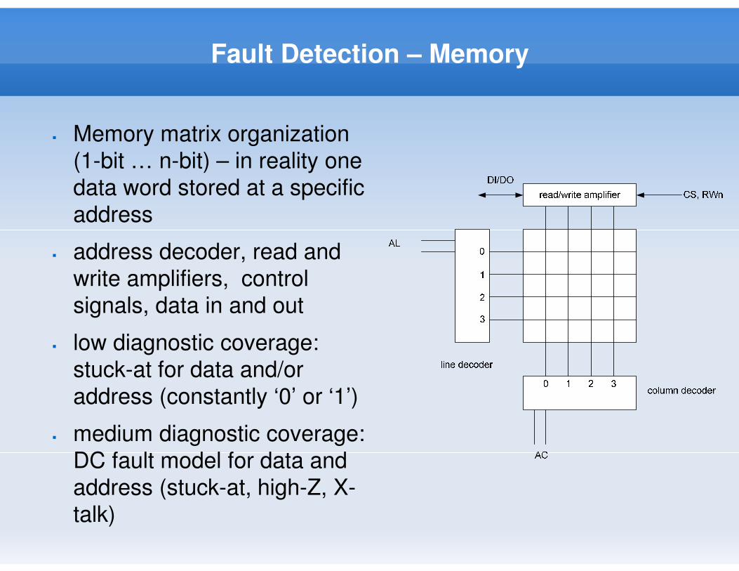
Fault Detection – Memory
� Memory matrix organization
(1-bit … n-bit) – in reality one
data word stored at a specific
address
� address decoder, read and
write amplifiers, control
signals, data in and out
� low diagnostic coverage:
stuck-at for data and/or
address (constantly ‘0’ or ‘1’)
� medium diagnostic coverage:
DC fault model for data and
address (stuck-at, high-Z, X-
talk)
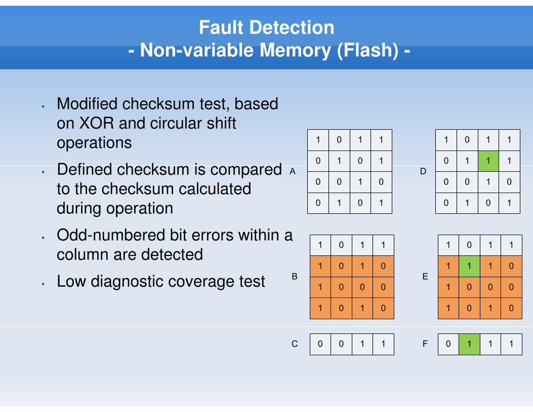
Fault Detection
- Non-variable Memory (Flash) -
� Modified checksum test, based
on XOR and circular shift
operations
� Defined checksum is compared
to the checksum calculated
during operation
� Odd-numbered bit errors within a
column are detected
� Low diagnostic coverage test
1 0 1 1
0 1 0 1
0 0 1 0
0 1 0 1
A
1 0 1 1
1 0 1 0
1 0 0 0
1 0 1 0
B
0 0 1 1C
D
E
F
1 0 1 1
0 1 1 1
0 0 1 0
0 1 0 1
1 0 1 1
1 1 1 0
1 0 0 0
1 0 1 0
0 1 1 1
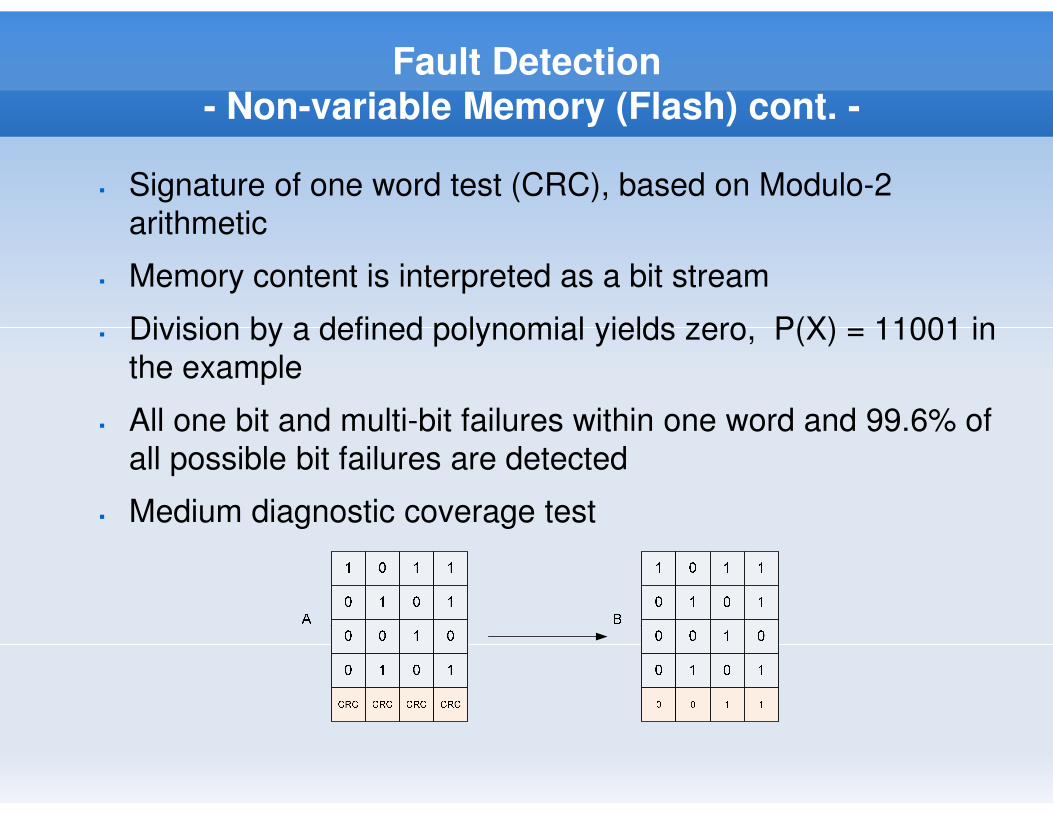
Fault Detection
- Non-variable Memory (Flash) cont. -
� Signature of one word test (CRC), based on Modulo-2
arithmetic
� Memory content is interpreted as a bit stream
� Division by a defined polynomial yields zero, P(X) = 11001 in
the example
� All one bit and multi-bit failures within one word and 99.6% of
all possible bit failures are detected
� Medium diagnostic coverage test
Fault Detection
- Non-variable memory (EEPROM) -
� EEPROM content is copied to SRAM and verified during
system initialization -> working copy
� All changes are made to working copy
� Working copy is written to EEPROM before power-down or
at defined slow cycles (wear-out effect!)
� EEPROM test is reduced to a RAM test – we work from
RAM data
Fault Detection
- Variable memory (SRAM) -
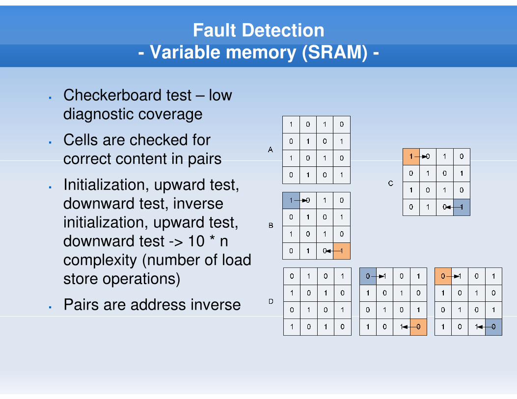
� Checkerboard test – low
diagnostic coverage
� Cells are checked for
correct content in pairs
� Initialization, upward test,
downward test, inverse
initialization, upward test,
downward test -> 10 * n
complexity (number of load
store operations)
� Pairs are address inverse
Fault Detection
- Variable memory (SRAM) cont. -
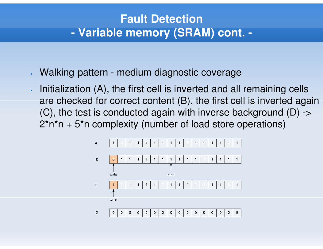
� Walking pattern - medium diagnostic coverage
� Initialization (A), the first cell is inverted and all remaining cells
are checked for correct content (B), the first cell is inverted again
(C), the test is conducted again with inverse background (D) ->
2*n*n + 5*n complexity (number of load store operations)
Fault Detection
- Variable memory (Stack) cont. -
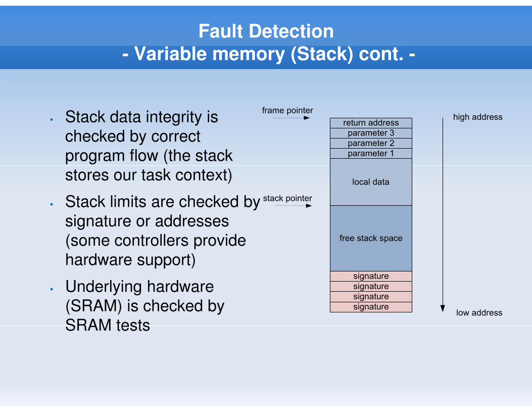
� Stack data integrity is
checked by correct
program flow (the stack
stores our task context)
� Stack limits are checked by
signature or addresses
(some controllers provide
hardware support)
� Underlying hardware
(SRAM) is checked by
SRAM tests
free stack space
signature
signature
signature
signature
return address
parameter 3
parameter 2
parameter 1
local data
frame pointer
stack pointer
high address
low address
Fault Detection Ctd.
- Example -
Slide32A. Walsch, IN2244
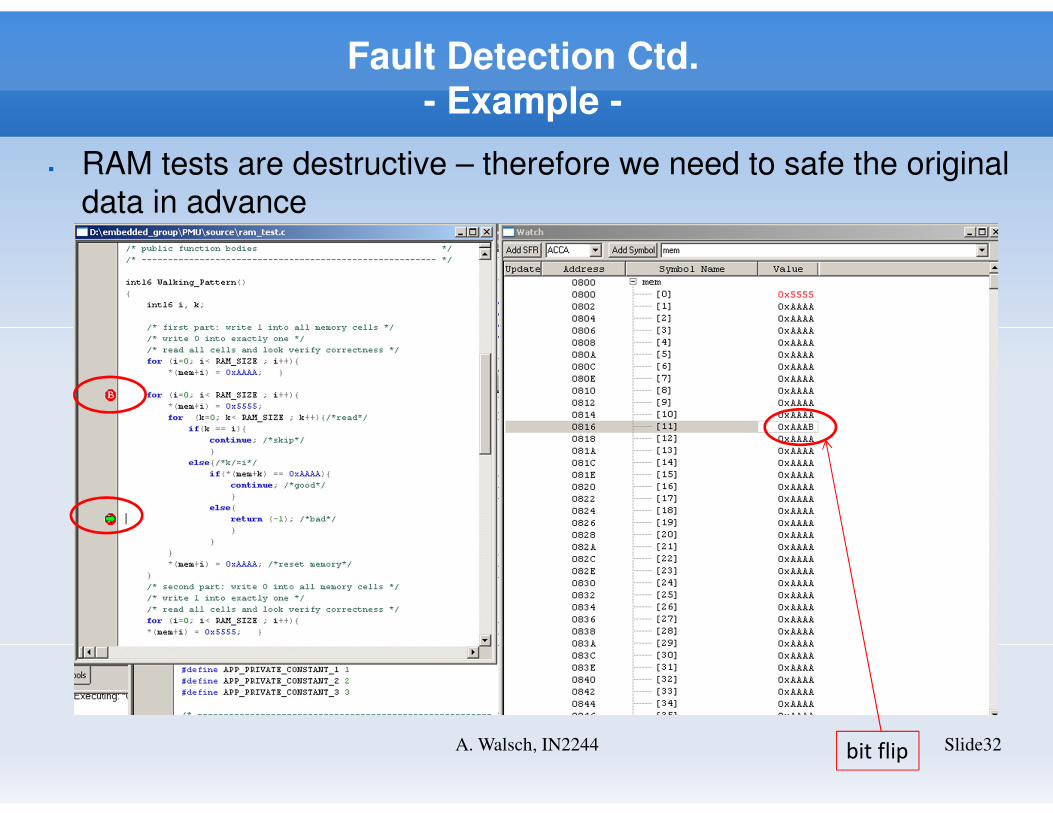
� RAM tests are destructive – therefore we need to safe the original
data in advance
bit flip
Software Mapping
Slide33A. Walsch, IN2244
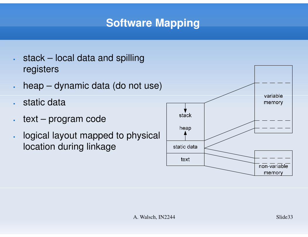
� stack – local data and spilling
registers
� heap – dynamic data (do not use)
� static data
� text – program code
� logical layout mapped to physical
location during linkage
Communication
Slide34A. Walsch, IN2244
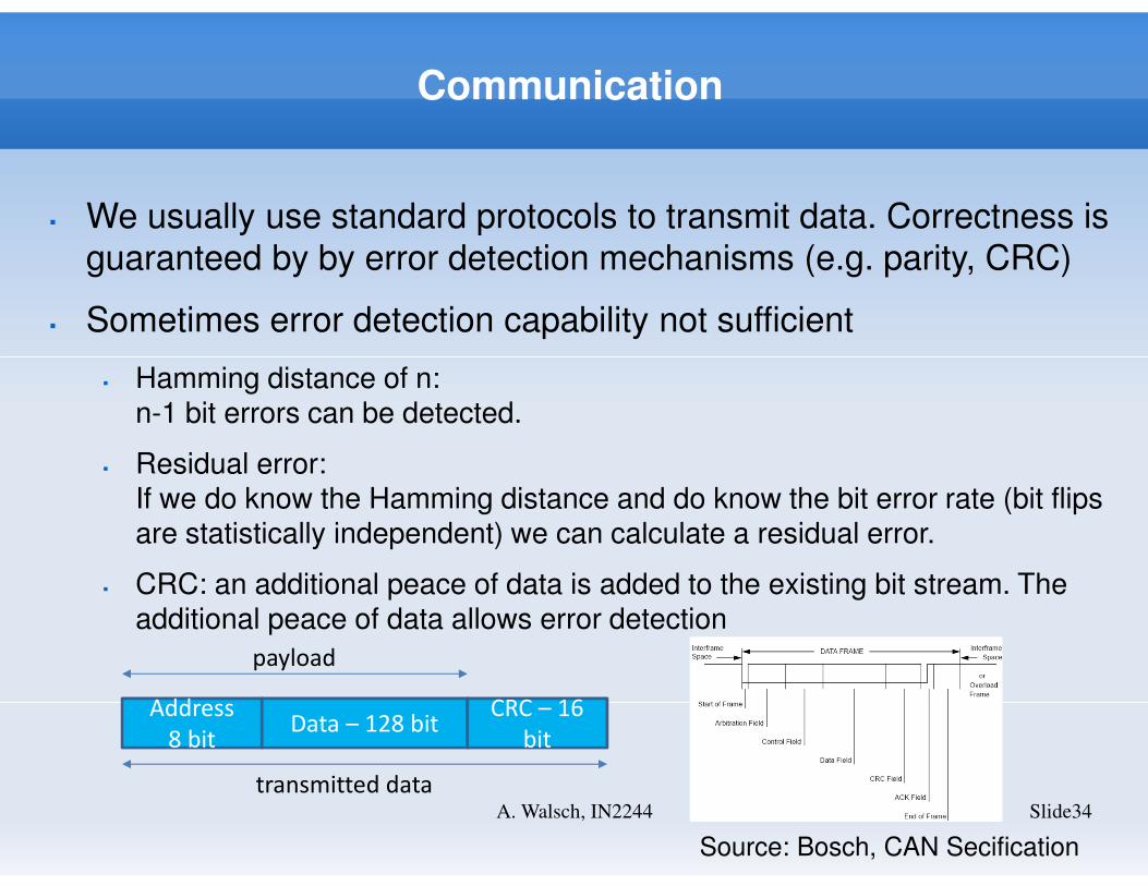
� We usually use standard protocols to transmit data. Correctness is
guaranteed by by error detection mechanisms (e.g. parity, CRC)
� Sometimes error detection capability not sufficient
� Hamming distance of n:n-1 bit errors can be detected.
� Residual error:If we do know the Hamming distance and do know the bit error rate (bit flips are statistically independent) we can calculate a residual error.
� CRC: an additional peace of data is added to the existing bit stream. The additional peace of data allows error detection
Address
8 bitData – 128 bit
CRC – 16
bit
payload
transmitted data
Source: Bosch, CAN Secification
Code Structure
Slide35A. Walsch, IN2244
� Software stored in ASCII files – what is a good way to structure
code?
� Object-orientation vs. precedural style
� Object-oriented programming languages (mostly C++) often not an
option
� Proven-in-use of tools challenge (safety-related software)
� Prior experience of team
� Coding in C in an object-oriented way
� Reusability
� Data encapsulation
� Function encapsulation
Code Structure Ctd.
Slide36A. Walsch, IN2244
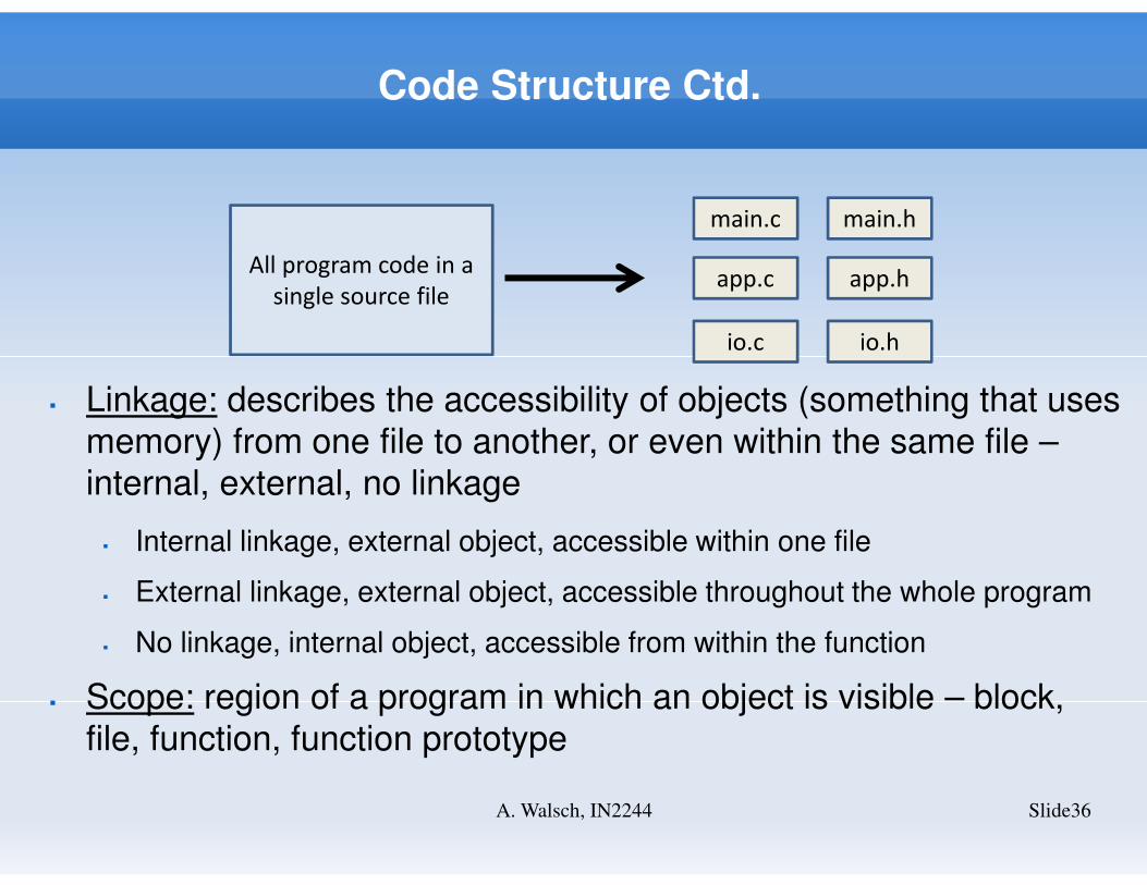
All program code in a
single source file
main.c main.h
app.c app.h
io.c io.h
� Linkage: describes the accessibility of objects (something that uses
memory) from one file to another, or even within the same file –
internal, external, no linkage
� Internal linkage, external object, accessible within one file
� External linkage, external object, accessible throughout the whole program
� No linkage, internal object, accessible from within the function
� Scope: region of a program in which an object is visible – block,
file, function, function prototype
Code Structure Ctd.
Slide37A. Walsch, IN2244
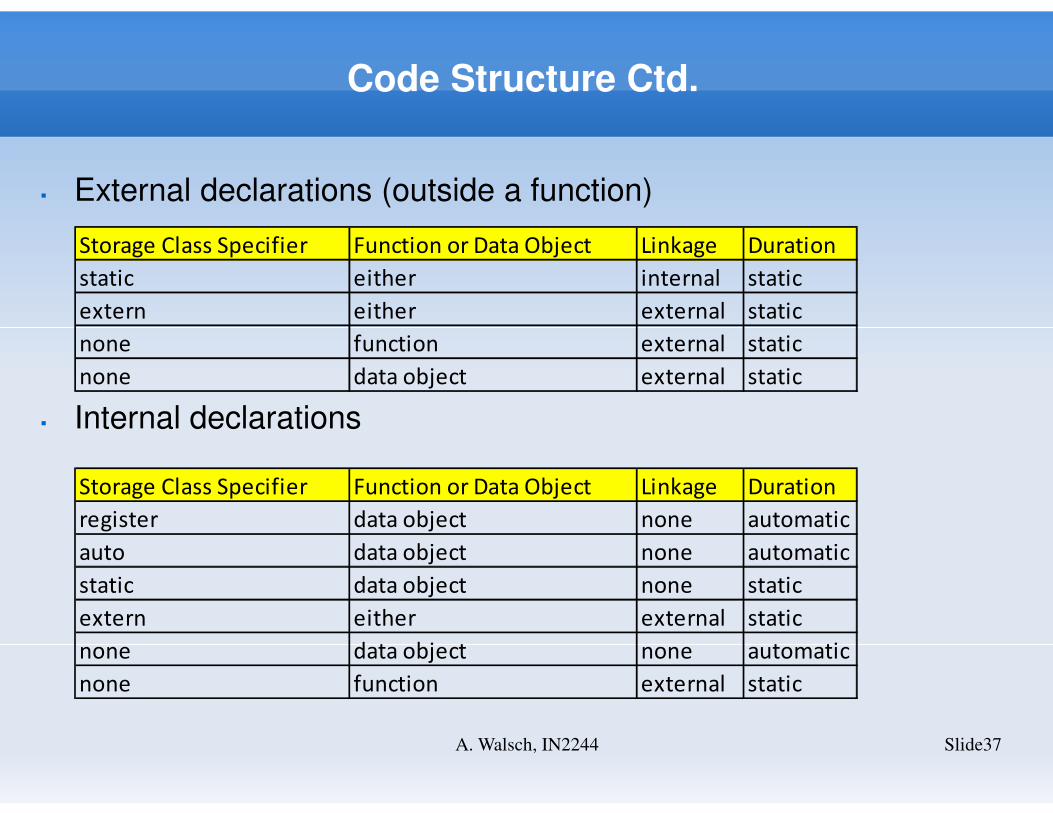
Storage Class Specifier Function or Data Object Linkage Duration
static either internal static
extern either external static
none function external static
none data object external static
� External declarations (outside a function)
� Internal declarations
Storage Class Specifier Function or Data Object Linkage Duration
register data object none automatic
auto data object none automatic
static data object none static
extern either external static
none data object none automatic
none function external static
Code Structure Ctd.
Slide38A. Walsch, IN2244
Code Structure Ctd.
Slide39A. Walsch, IN2244


![[Peggy McColl, Neale Donald Walsch] Your Destiny](https://img.pdfslide.us/doc/110x75/577cd6cd1a28ab9e789d494c/peggy-mccoll-neale-donald-walsch-your-destiny.jpg)