Embed Size (px)
Citation preview

TECHNICAL REPORT
© The Broadband Forum. All rights reserved.
TR-198 DQS: DQM systems functional architecture and
requirements
Issue: 2
Issue Date: November 2012

DQS: DQM systems functional architecture and requirements TR-198 Issue 2
November 2012 © The Broadband Forum. All rights reserved 2 of 73
Notice
The Broadband Forum is a non-profit corporation organized to create guidelines for broadband
network system development and deployment. This Broadband Forum Technical Report has
been approved by members of the Forum. This Broadband Forum Technical Report is not
binding on the Broadband Forum, any of its members, or any developer or service provider. This
Broadband Forum Technical Report is subject to change, but only with approval of members of
the Forum. This Technical Report is copyrighted by the Broadband Forum, and all rights are
reserved. Portions of this Technical Report may be copyrighted by Broadband Forum members.
This Broadband Forum Technical Report is provided AS IS, WITH ALL FAULTS. ANY
PERSON HOLDING A COPYRIGHT IN THIS BROADBAND FORUM TECHNICAL
REPORT, OR ANY PORTION THEREOF, DISCLAIMS TO THE FULLEST EXTENT
PERMITTED BY LAW ANY REPRESENTATION OR WARRANTY, EXPRESS OR
IMPLIED, INCLUDING, BUT NOT LIMITED TO, ANY WARRANTY:
(A) OF ACCURACY, COMPLETENESS, MERCHANTABILITY, FITNESS FOR A
PARTICULAR PURPOSE, NON-INFRINGEMENT, OR TITLE;
(B) THAT THE CONTENTS OF THIS BROADBAND FORUM TECHNICAL REPORT
ARE SUITABLE FOR ANY PURPOSE, EVEN IF THAT PURPOSE IS KNOWN TO
THE COPYRIGHT HOLDER;
(C) THAT THE IMPLEMENTATION OF THE CONTENTS OF THE TECHNICAL
REPORT WILL NOT INFRINGE ANY THIRD PARTY PATENTS, COPYRIGHTS,
TRADEMARKS OR OTHER RIGHTS.
By using this Broadband Forum Technical Report, users acknowledge that implementation may
require licenses to patents. The Broadband Forum encourages but does not require its members
to identify such patents. For a list of declarations made by Broadband Forum member
companies, please see http://www.broadband-forum.org. No assurance is given that licenses to
patents necessary to implement this Technical Report will be available for license at all or on
reasonable and non-discriminatory terms.
ANY PERSON HOLDING A COPYRIGHT IN THIS BROADBAND FORUM TECHNICAL
REPORT, OR ANY PORTION THEREOF, DISCLAIMS TO THE FULLEST EXTENT
PERMITTED BY LAW (A) ANY LIABILITY (INCLUDING DIRECT, INDIRECT, SPECIAL,
OR CONSEQUENTIAL DAMAGES UNDER ANY LEGAL THEORY) ARISING FROM OR
RELATED TO THE USE OF OR RELIANCE UPON THIS TECHNICAL REPORT; AND (B)
ANY OBLIGATION TO UPDATE OR CORRECT THIS TECHNICAL REPORT.
Broadband Forum Technical Reports may be copied, downloaded, stored on a server or
otherwise re-distributed in their entirety only, and may not be modified without the advance
written permission of the Broadband Forum.
The text of this notice must be included in all copies of this Broadband Forum Technical Report.

DQS: DQM systems functional architecture and requirements TR-198 Issue 2
November 2012 © The Broadband Forum. All rights reserved 3 of 73
Issue History
Issue Number Approval Date Publication Date Issue Editor Changes
1 September 2010 Peter Adams,
ADTRAN
Christopher Croot,
BT
Original
2 26 November
2012
14 January 2013 Christopher Croot,
BT
Additional
requirements
and use cases
Comments or questions about this Broadband Forum Technical Report should be directed to
Editor Christopher Croot BT
Operations & Network Management
WG Chair
Peter Adams ADTRAN
Vice Chair Moti Morgenstern ECI
Chief Editor Michael Hanrahan Huawei Technologies

DQS: DQM systems functional architecture and requirements TR-198 Issue 2
November 2012 © The Broadband Forum. All rights reserved 4 of 73
TABLE OF CONTENTS
EXECUTIVE SUMMARY .......................................................................................................... 7
1 PURPOSE AND SCOPE ...................................................................................................... 8
1.1 PURPOSE .......................................................................................................................... 8
1.2 SCOPE .............................................................................................................................. 8
2 REFERENCES AND TERMINOLOGY ............................................................................ 9
2.1 CONVENTIONS ................................................................................................................. 9 2.2 REFERENCES .................................................................................................................... 9 2.3 DEFINITIONS .................................................................................................................. 11
2.4 ABBREVIATIONS ............................................................................................................ 11
3 TECHNICAL REPORT IMPACT ................................................................................... 13
3.1 ENERGY EFFICIENCY ...................................................................................................... 13 3.2 IPV6 ............................................................................................................................... 13
3.3 SECURITY ....................................................................................................................... 13 3.4 PRIVACY ........................................................................................................................ 13
4 DQM SYSTEM FUNCTIONAL ARCHITECTURE ...................................................... 14
4.1 DATA SOURCES .............................................................................................................. 16 4.2 DATA COLLECTION FUNCTION (DCF) ........................................................................... 16
4.3 DQM ANALYSIS AND DIAGNOSIS FUNCTION (ADF) ..................................................... 17 4.4 NEW PROFILE SELECTION FUNCTION ............................................................................. 17 4.5 PROFILE CONFIGURATION FUNCTION ............................................................................. 17
4.6 DQM CONTROL FUNCTION ............................................................................................ 17
4.7 QUALITY EXCEPTION GENERATION FUNCTION .............................................................. 18
5 DESCRIPTION OF INTERFACES ................................................................................. 19
5.1 STANDARD INTERFACES ................................................................................................. 19
5.2 OTHER INTERFACES ....................................................................................................... 20 5.3 CONSISTENCY AND ACCURACY REQUIREMENTS FOR COLLECTED DSL PARAMETERS .. 21
6 DATA COLLECTION FUNCTION ................................................................................. 23
6.1 DSL PARAMETERS AND LINE TESTING FUNCTIONS ....................................................... 23 6.1.1 Collected DSL Parameters and Line Testing Parameters ........................................ 23 6.1.2 Collected DSL Related Notifications ........................................................................ 35
6.2 DATA COLLECTION FUNCTION IMPLEMENTATION ......................................................... 36
6.3 DATA COLLECTION FUNCTION “NORTHBOUND” INTERFACE ......................................... 36 6.3.1 Interface Primitives ................................................................................................... 36 6.3.2 Format of the Information Fields ............................................................................. 44 6.3.3 Interface Protocol ..................................................................................................... 45
6.4 DATA COLLECTION FUNCTION “SOUTHBOUND” INTERFACE.......................................... 45
6.5 DCF PERFORMANCE REQUIREMENTS ............................................................................ 46 6.5 FUNCTIONAL REQUIREMENTS ........................................................................................ 48

DQS: DQM systems functional architecture and requirements TR-198 Issue 2
November 2012 © The Broadband Forum. All rights reserved 5 of 73
7 DQM MANAGEMENT ENTITY ..................................................................................... 49
7.1 DQM-ME DATA COLLECTION PERFORMANCE REQUIREMENTS ...................................... 49 7.2 COLLECTED DSL RELATED NOTIFICATIONS .................................................................. 50
8 DQM ANALYSIS & DIAGNOSIS FUNCTION ............................................................. 51
8.1 DIAGNOSIS FUNCTION .................................................................................................... 51 8.2 ANALYSIS FUNCTION ..................................................................................................... 51
9 NEW PROFILE SELECTION FUNCTION.................................................................... 52
10 PROFILE CONFIGURATION FUNCTION................................................................... 53
10.1 PROFILE CONFIGURATION FUNCTION “NORTHBOUND” INTERFACE ............................... 53
10.1.1 Interface Primitives ............................................................................................... 53
11 DQM CONTROL FUNCTION ......................................................................................... 57
12 QUALITY EXCEPTION GENERATION FUNCTION ................................................ 58

DQS: DQM systems functional architecture and requirements TR-198 Issue 2
November 2012 © The Broadband Forum. All rights reserved 6 of 73
List of Figures
Figure 1 - DQM system functional architecture ........................................................................... 15 Figure 2 - Data Collection Function ............................................................................................. 36
Figure 3 - Profile Configuration Function .................................................................................... 53 Figure 4 - The Reference Model from the ATIS DSM TR ........................................................... 59 Figure 5 - Relation of DSM TR Reference to DSL Quality Suite Functional Reference Model . 60 Figure 6 - Centralised Data Collection from Management Server ............................................... 66 Figure 7 - Distributed Data Collection Function in NE ................................................................ 66
Figure 8 - Distributed Data Collection Function external to NE .................................................. 67 Figure 9 - Profile Configuration Function on same physical entity as NPSF ............................... 68 Figure 10 - Profile Configuration Function located in the Element Manager .............................. 68 Figure 11 - Profile Configuration Function located in the Network Element .............................. 69
List of Tables
Table 1 - Scalar parameters to be supported for collection .......................................................... 25
Table 2 - Framing parameters to be supported for collection ....................................................... 27 Table 3 - Performance monitoring parameters to be supported for collection ............................. 28 Table 4 - Vectorial parameters to be supported for collection...................................................... 29
Table 5 - Status parameters to be supported for collection ........................................................... 30 Table 6 - xTU info parameters to be supported for collection ...................................................... 32
Table 7 - Vector of Profiles parameters to be supported for collection ........................................ 32 Table 8 - Equipment inventory parameters to be supported for collection................................... 34 Table 9 - Threshold crossing notifications to be supported for the following counters ............... 35 Table 10 - link status notifications to be supported ...................................................................... 35 Table 11 - Interface Primitives and Information Fields ................................................................ 36
Table 12 - Create_collection_task primitive configurable parameters ......................................... 37 Table 13 - Create_collection_task.request primitive parameters .................................................. 40
Table 14 - DCF minimum required processing/memory/data transfer capabilities ...................... 47 Table 15 - DQM-ME minimum required processing/memory/data transfer capabilities ............. 50 Table 16 - Interface Primitives and Information Fields ................................................................ 53
Table 17 - Create_profile_configuration_task primitive configurable parameters....................... 54 Table 18 - Create_profile_configuration_task.confirm primitive parameters .............................. 55 Table 19 - Basic use cases ............................................................................................................ 62 Table 20 - Combined use cases ..................................................................................................... 65 Table 21 - Proposed use cases for Profile Configuration: ............................................................ 71

DQS: DQM systems functional architecture and requirements TR-198 Issue 2
November 2012 © The Broadband Forum. All rights reserved 7 of 73
Executive Summary
TR-198 is a component of the DQS (DSL Quality Suite) which is an on-going initiative of the
Broadband Forum to identify the building blocks (reference features and tools, equipment and
system requirements, network strategies and practices) to be used by manufacturers and Service
Providers to develop solutions that enable pro-active and efficient maintenance of broadband
lines and services.
DSL Quality Management (DQM) encompasses a range of techniques that seek to monitor,
analyse and improve performance and/or stability of a DSL line or a group of DSL lines.
Generally speaking this is based on the following DQM loop:
This concept can be applied to operational phases like Provisioning and Assurance typically
targeting a single DSL line. DQM techniques can be conceived also for the Trend Analysis phase
encompassing groups of DSL lines and aggregation of Network Elements (NEs). Finally DQM
can also feed the Network or the Infrastructure Planning phases which again involve wide
portions of the access network.
A functional architecture for DQM is described and the interfaces required between functional
blocks identified. DQM systems require the collection of performance, status, test and other data
which is analysed to enable decisions on re-configuration or other actions to be made. The
detailed requirements for a data collection function and the interfaces to it are given and
encompass the data to be collected, the mechanism for collection and the performance of the
interfaces.
Other functions and interfaces of the DQM loop above are described as well.
Updates for Issue 2 include:
Issue 2 adds additional DCF requirements and updates others in order to improve their definition.
Additions have also been made to the Profile Configuration Function and more Profile
Configuration use cases have been defined.

DQS: DQM systems functional architecture and requirements TR-198 Issue 2
November 2012 © The Broadband Forum. All rights reserved 8 of 73
1 Purpose and Scope
1.1 Purpose
The DSL Quality Suite (DQS) is composed of several documents which encompass various
topics in the field of ensuring the quality and stability of DSL lines, i.e. DSL Quality
Management (DQM).
DQM is a generic term for techniques which use DSL line performance, status and test data, and
other data as inputs to an analysis and diagnosis function which leads to a potential (soft or hard)
corrective action whose aim is the amelioration of problems or improved performance. If a
problem cannot be solved by a new set of DSL parameters then DQM provides a diagnosis for
other actions to be taken.
DQM is also useful for spectral compatibility, in particular the DQM system can identify and
help ameliorate incompatibilities between multiple lines under its management.
TR-198 specifies the architecture, and the functional and performance requirements for DQM
systems.
1.2 Scope
TR-198 provides an architecture that identifies the key functions of a DQM system and the
external functions on which it depends and to which it delivers its output. The requirements for
each functional block are given. Interfaces between the functional blocks and between the
functional blocks and the external functions are identified. Existing standards that are relevant to
these interfaces are indicated and the need for new standardized interfaces identified.
Requirements on the interfaces are listed.
TR-198 encompasses:
definition of the functional architecture of a DQM system
high level description of the interfaces of a DQM system
detailed specification of the functional and performance requirements for the Northbound
interface of the Data Collection Function within a DQM system
requirements for the Southbound interface for the Data Collection Function within a
DQM system
specification of the performance requirements for the DQM-ME of a Network Element
within a DQM system
high level description and requirements of other functions within a DQM system
detailed specification of the functional requirements for the Northbound interface of the
Profile Configuration Function within the DQM system
TR-198 is focused on DSL technologies that are currently addressed by G.997.1 [23]. Extension
to SHDSL is for further study.

DQS: DQM systems functional architecture and requirements TR-198 Issue 2
November 2012 © The Broadband Forum. All rights reserved 9 of 73
2 References and Terminology
2.1 Conventions
In this Technical Report, several words are used to signify the requirements of the specification.
These words are always capitalized. More information can be found be in RFC 2119 [9].
MUST This word, or the term “REQUIRED”, means that the definition is an
absolute requirement of the specification.
MUST NOT This phrase means that the definition is an absolute prohibition of the
specification.
SHOULD This word, or the term “RECOMMENDED”, means that there could
exist valid reasons in particular circumstances to ignore this item, but
the full implications need to be understood and carefully weighed
before choosing a different course.
SHOULD NOT This phrase, or the phrase "NOT RECOMMENDED" means that there
may exist valid reasons in particular circumstances when the particular
behaviour is acceptable or even useful, but the full implications need
to be understood and the case carefully weighed before implementing
any behaviour described with this label.
MAY This word, or the term “OPTIONAL”, means that this item is one of
an allowed set of alternatives. An implementation that does not
include this option MUST be prepared to inter-operate with another
implementation that does include the option.
2.2 References
The following references are of relevance to this Technical Report. At the time of publication,
the editions indicated were valid. All references are subject to revision; users of this Technical
Report are therefore encouraged to investigate the possibility of applying the most recent edition
of the references listed below.
A list of currently valid Broadband Forum Technical Reports is published at www.broadband-
forum.org.
Document Title Source Year [1] TR-105
Issue 2 ADSL2/ADSL2plus Functionality Test Plan BBF 2011
[2] TR-114 VDSL2 Performance Test Plan BBF 2009

DQS: DQM systems functional architecture and requirements TR-198 Issue 2
November 2012 © The Broadband Forum. All rights reserved 10 of 73
[3] TR-115
Issue 2
VDSL2 Functionality Test Plan BBF 2012
[4] TR-130 xDSL EMS to NMS Interface Functional
Requirements
BBF 2006
[5] TR-138 Accuracy Tests for Test Parameters BBF 2009
[6] TR-176 ADSL2Plus Configuration Guidelines for IPTV BBF 2008
[7] TR-252
Issue 2
xDSL Protocol-Independent Management Model BBF 2012
[8] RFC 1213 MIB-II IETF 1991
[9] RFC 2119 Key words for use in RFCs to Indicate Requirement
Levels
IETF 1997
[10] RFC 2662 Definitions of Managed Objects for the ADSL Lines IETF 1999
[11] RFC 2863 The Interfaces Group MIB IETF 2000
[12] RFC 3440 Definitions of Extension Managed Objects for ADSL IETF 2002
[13] RFC 4133 Entity MIB (Version 3) IETF 2005
[14] RFC 4706 Definitions of Managed Objects for ADSL2 IETF 2006
[15] RFC 5650 Definitions of Managed Objects for VDSL2 IETF 2009
[16] G.992.1 Asymmetric digital subscriber line (ADSL)
transceivers
ITU-T 1999
[17] G.992.2 Splitterless asymmetric digital subscriber line
(ADSL) transceivers
ITU-T 1999
[18] G.992.3 Asymmetric digital subscriber line transceivers 2
(ADSL2)
ITU-T 2005
[19] G.992.4 Splitterless asymmetric digital subscriber line
transceivers 2 (splitterless ADSL2)
ITU-T 2002
[20] G.992.5 Asymmetric Digital Subscriber Line (ADSL)
transceivers - Extended bandwidth ADSL2
(ADSL2plus)
ITU-T 2005
[21] G.993.2 Very high speed digital subscriber line transceivers 2
(VDSL2)
ITU-T 2006
[22] G.996.2 Single-ended line testing for digital subscriber lines
(DSL)
ITU-T 2009
[23] G.997.1 Physical layer management for digital subscriber
line (DSL) transceivers
ITU-T 2012
[24] M.3000 Overview of TMN Recommendations ITU-T 2000
[25] M.3010 Principles for a telecommunications management ITU-T 2000

DQS: DQM systems functional architecture and requirements TR-198 Issue 2
November 2012 © The Broadband Forum. All rights reserved 11 of 73
network
[26] ATIS-
0600007
ATIS DSM Technical Report ATIS 2007
[27] GR-831 OTGR Section 12.1: Operations Application
Messages – Language For Operations Application
Messages
Telcordia
Technolo
gies
1996
[28] MTOSI 2 Multi-Technology Operations Systems Interface TM
Forum
2009
2.3 Definitions
The following terminology is used throughout this Technical Report.
DQM DSL Quality Management (DQM) is the abstract capability of pro-active and
efficient control of the quality and stability of xDSL lines.
2.4 Abbreviations
This Technical Report uses the following abbreviations:
ADF Analysis & Diagnosis Function
ADSL Asymmetric Digital Subscriber Line
ADSL2 Asymmetric Digital Subscriber Line 2
ADSL2plus Asymmetric Digital Subscriber Line 2plus
AN Access Node
CPE Customer Premise Equipment
DCF Data Collection Function
DPBO Downstream Power Back-Off
DQM DSL Quality Management
DQMCF DSL Quality Management Control Function
DQM-ME DSL Quality Management - Management Entity
DQS DSL Quality Suite
DSL Digital Subscriber Line
DSLAM Digital Subscriber Line Access Multiplexor
DSM Dynamic Spectrum Management
EMS Element Management System
ME Management Entity
MIB Management Information Base
MTOSIv2 Multi-Technology Operations Systems Interface v2

DQS: DQM systems functional architecture and requirements TR-198 Issue 2
November 2012 © The Broadband Forum. All rights reserved 12 of 73
NE Network Element
NMS Network Management System
NPSF New Profile Selection Function
OSS Operations Support System
PM Performance Monitoring
RFC Request for Comment
SHDSL Single-Pair High-speed Digital Subscriber Line
SMC Spectrum Management Centre
TR Technical Report
UPBO Upstream Power Back-Off
VDSL2 Very high bit rate Digital Subscriber Line 2
VoP Vector of Profiles

DQS: DQM systems functional architecture and requirements TR-198 Issue 2
November 2012 © The Broadband Forum. All rights reserved 13 of 73
3 Technical Report Impact
3.1 Energy Efficiency
DQM techniques can enable improvements in energy efficiency of DSL deployments. Although
these techniques are not specifically in the scope of TR-198 the architecture and interfaces
described are meant to support DQM algorithms and techniques some of which could enable
improvements in energy efficiency.
3.2 IPv6
TR-198 has no impact on IPv6
3.3 Security
DSL Quality Management raises security issues in the following two areas:
The interfaces specified in TR-198, as is typical of any telecommunication
management system, will need to be secured against abuse using appropriate security
practices.
One of the factors related to DSL Quality is ensuring that both the end user’s services
and the overall stability of the network are protected against malicious attacks and
other security threats.
Specific requirements with respect to these issues are for further study.
3.4 Privacy
A DQM system may store information that could be considered private to individuals or
companies. It is the responsibility of the operator implementing such a system to ensure that it
complies with any regulatory, legal or commercial privacy requirements. The specifics of
meeting those requirements are outside the scope of this document.

DQS: DQM systems functional architecture and requirements TR-198 Issue 2
November 2012 © The Broadband Forum. All rights reserved 14 of 73
4 DQM System Functional Architecture
This section describes the functional architecture of a generic DSL Quality Management (DQM)
system along with the interfaces between the functional blocks and between the functional
blocks and external functions.
DQM encompasses a range of techniques that seek to monitor, analyse and improve performance
and/or stability of a DSL line or a group of DSL lines.
Generally speaking this is based on the following DQM loop:
The soft actions are the most frequent as they represent the promptest, seamless and
operationally cost-effective way to intervene on DSL lines. This encompasses the application of
a new DSL operational profile, a line reset (i.e. reissuing the same profile) and an alarm or PM
threshold profile change.
The DQM loop can also be closed with a hard corrective action which could encompass an
intervention at the infrastructure level (e.g. change of twisted pair, user splitter or cabling
interventions) or equipment level (e.g. CPE change, CPE software upgrade up to NE release
upgrade). These actions are more extreme and onerous and are applied if the identified problem
is so severe it cannot be solved via a profile change or a more “invasive” action is advisable to
solve it in a more effective and durable way.
The DQM loop can be applied to a single DSL line or to multiple lines and this concept can be
applied to the various network operational phases such as Provisioning, Assurance and Trend
Analysis, and the Network or Infrastructure Planning.

DQS: DQM systems functional architecture and requirements TR-198 Issue 2
November 2012 © The Broadband Forum. All rights reserved 15 of 73
1
QoE
Inputs
DQM Analysis & Diagnosis
Function
Profile
Configuration
DQM Management
Entity (DQM-ME)
DSL Performance,
Status and Test
Parameters
Other Data
TR-252
G.997.1
G.996.2 B A
Other Inputs
Data
Triggers
DSL Configuration
Parameters Line Test Parameters
Data Collection
Function
DQM Control
DQM Control
DQM Control
DQM Control
DQM Control
DQM Control
DQM
Triggers
E
(already or to be)
Standardized I/F
Network Profiles
DSL Profiles
Alarm Profiles
Line-Trouble
Information Current DSL
Profile
Hard Corrective actions
e.g. truck rolls, pair change, CPE
change, messages or reports to
other operations functionalities.
Regulatory
Constraints
Constraints
Operator
Constraints
f
New Profile Selection
c’
G
z
x
Y
w
u
Other I/F
s t
c”
Quality
Exception
Generation
Service
Constraints
Customer
Constraints
Network Information
r c
Historical Data
h
Soft corrective action
TR-130, G.997.1, TR-138, TR-
252, G.992.1-5, G.993.2, TR-
105, TR-115
Figure 1 - DQM system functional architecture

DQS: DQM systems functional architecture and requirements TR-198 Issue 2
November 2012 © The Broadband Forum. All rights reserved 16 of 73
Figure 1 shows the DQM system architectural block diagram. The coloured blocks within the
solid lines are the functions that are specific to the DQM system. The other blocks are the
functions external to the DQM system that it interfaces to. The diagram also indicates in BLUE
where it could be desirable to standardize interfaces between the functional blocks. It also
indicates in RED the interfaces for which standards exist, or are to be defined, that are relevant to
these interfaces. The control flows within the DQM system and its interactions with the other
functional blocks are not shown in Figure 1.
This model includes concepts found in the reference model in Section 4/ATIS Dynamic
Spectrum Management Technical Report (ATIS DSM TR [26]). Appendix A provides a detailed
discussion of the relation between the model in the DSM TR and that in Figure 1.
In a DQM system, the above Data Collection Function (DCF), Profile Configuration Function
(PCF) and Analysis and Diagnosis Function (ADF) blocks ought to be able to deal with NEs that
are currently deployed in a Network Operator’s network as well as new equipment. The
discussion in Sections 5 and 6 of this Technical Report specifically addresses the functional
requirements of the DCF and PCF interfaces to NEs based on G.997.1 [23], existing DSL
Interface MIBs defined by the IETF, and common industry practices with respect to inventory
information at the time of publication of this Technical Report. One of the functions of both the
DCF and PCF is performing the mediation implied by the management interfaces supported by
the network elements.
4.1 Data Sources
The primary sources of data to drive a DQM system are the DSL Performance, Status and Test
Parameters combined with Network Element inventory and service state (e.g. whether a DSL
interface is currently configured or enabled) information that is available from the DQM
Management Entity (DQM-ME). The DQM-ME configures and retrieves parameters in and
from the DSL modems in the NE. Standardized line test parameters could also be available from
DSL modems as defined by G.996.2 [22] and by possible future enhancement to the standard
management interfaces defined in G.997.1 [23]. In addition external data from the Network
Operator’s operations support systems could be utilised.
4.2 Data Collection Function (DCF)
The sources of data are the inputs to a Data Collection Function (DCF) which collects the data
and presents it to the DQM Analysis and Diagnosis Function (ADF) on demand. The function
includes the facility to poll data from inputs where this is possible and to accept new data when
autonomously offered.

DQS: DQM systems functional architecture and requirements TR-198 Issue 2
November 2012 © The Broadband Forum. All rights reserved 17 of 73
4.3 DQM Analysis and Diagnosis Function (ADF)
At the heart of the DQM process is the DQM Analysis & Diagnosis Function (ADF). It examines
the data collected and the currently used DSL profile, analyses why there is a problem or how the
performance could be improved, and diagnoses any line troubles. Network Information and Line-
Trouble Information supports this diagnosis.
The aim is to provide a reliable and complete diagnosis of the line, group(s) of lines and group(s)
of NEs subject to the analysis and indicate one or more corrective actions. The most frequent
action is to provide to the DQM-ME a new set of configuration parameters to be applied to the
DSL modem(s) that are expected to fix the problem or to improve the performance if possible. If
not other actions, such as communication with the network operator’s other OSS, generation of
reports, or requests for other processes such as truck rolls could occur. Fundamentally there is
much more than a truck roll that can occur if re-profiling does not resolve a problem.
The role of the ADF is to analyse the performance of the DSL service based on the collected
information, the customer’s ordered service and the Network Operator’s criteria of appropriate
operation of that service. As shown in Figure 1, the ADF could also use stored historical
information. Problems due to specific degradations ought to be detected or the service could be
improved using DQM techniques even though no specific degradation is found. In those cases
where the ADF cannot initiate re-profiling to address the problem the Network Operator’s
troubleshooting process needs to be kicked off. However, if the problem is solvable by the use
of a new profile, i.e. by reconfiguration of the DSL Service, then the ADF needs to provide to the
New Profile Selection Function (NPSF) sufficient information for it to select one of the available
profiles.
4.4 New Profile Selection Function
Configuration parameters are contained in a profile. So the output of the DQM Analysis and
Diagnosis Function enables a new profile to be selected from a profile database by the New
Profile Selection Function. The selected profile needs to conform to constraints imposed by
operator procedures, network practices and regulation.
4.5 Profile Configuration Function
The new profile is configured in the specific format required by the equipment deployed in the
network and configured on the network element by the DQM Profile Configuration Function
(PCF).
4.6 DQM Control Function
For a sophisticated DQM solution direct control of the configuration parameters values or the
initialization policy would be very useful. However, any DQM system can only work with the
management interface provided by Network Elements and this Technical Report deals only with
interfaces which are based on established DSL management standards. Also, the configuration

DQS: DQM systems functional architecture and requirements TR-198 Issue 2
November 2012 © The Broadband Forum. All rights reserved 18 of 73
parameters are managed through the application of profiles. A profile is a set of values, one for
each configuration parameter, which needs to be set in the xDSL MIB and is typically managed
as a single management object. That is when a specific profile is assigned to a DSL Line, all the
parameters dealt with by configuration profiles for that type of network equipment are set based
on the specific profile selected. TR-252 [7] and TR-176 [6] provide a discussion of DSL profiles,
their use and relation to DSL Management Standards.
The number of predefined profiles is constrained, for example, by practical storage limitations in
DSLAMs. One of the aims of TR-252 [7] is to make the number of possibilities for profiles as
large as possible so facilitating better DQM.
The coordination of the DQM process occurs in the DQM Control Function (DQM-CF). Among
the functions provided by the DQM-CF are:
Scheduling any re-profiling to minimize the service effects seen by the customer
of any retrains required to implement the new profile on the DSL service. It
controls when DQM activities are initiated and it can include policies that prevent
unwanted service interruption, or schedule them for an appropriate time.
Managing the data collection process to control the effect on management traffic
to and from the network elements required to support DQM. The DQM-CF ought
to prevent overuse of both the management interfaces on the Network Elements
and of the Network Operator’s management network.
The DQM-CF can process different triggers of the DQM process which could
arise either from the Network Elements, other management process, or manual
intervention by the Network Operator’s technicians and manage the DQM process
accordingly. This is done by means of commands/ responses between the DQM-
CF and the functional blocks (these are not explicitly shown in Figure 1 and are
for further study).
4.7 Quality Exception Generation Function
The Quality Exception Generation Function obtains data and exceptions from various DQM-
MEs in the network and determines if the quality of performance is such that the DQM process
ought to be invoked for particular DSL lines. If it is then a trigger is sent to the DQM Control
Function.
Examples of triggers include the processing of DSL Performance, Status and Test data, either by
the Quality Exception Generation Function or by the Data Collection Function. Other triggers are
external to the DQM process, e.g. time of day for routine data collection, or a trigger from a
customer complaint to a call centre.

DQS: DQM systems functional architecture and requirements TR-198 Issue 2
November 2012 © The Broadband Forum. All rights reserved 19 of 73
5 Description of Interfaces
This section provides a description of the interfaces between the functional blocks identified in
Figure 1.
Interfaces labelled with a capital letter in Figure 1 are already standardized or recommended to
be standardized and are described in Section 5.1.
All other interfaces shown in Figure 1 are for further study.
5.1 Standard Interfaces
Interface A
The parameters available across this interface are those defined in G.996.2 [22] and also those
test parameters that are defined for retrieval both in SHOWTIME and in the special diagnostic
mode in G.997.1 [23].
The specific functional requirements for this interface for the architecture defined in Figure 1 are
described in Section 6.4.
Interface B
The parameters available across this interface are defined in G.997.1 and contained in the object
model in TR-252 [7]. RFCs 1213 [8], 2662 [10], 3440 [12], 4706 [14] and 5650 [15] provide
object models subject to the relevant technology related to this interface. TR-138 [5] addresses
the accuracy requirements of DSL test parameters while Section 5.12, 6 & 7 in TR-105 [1]
define requirements for consistency with actual line conditions of certain reported ADSL2/2plus
parameters, and Section 7/TR-114 [2] define requirements for consistency with actual line
conditions of certain reported VDSL2 parameters. TR-130 [4] addresses the functional
requirements of the EMS-NMS interface.
In addition to the collection of DSL parameters, Interface ‘B’ ought to also support collecting of
inventory and equipment state information required by the DQM functions. Such information is
typically defined into hierarchical models of the equipment often based upon specifications that
are commonly used in the industry. Examples of such models are the TID/SID/AID model
defined in Section 12.1/GR-831 [27], the TMN [Telecommunications Management Network]
models defined in the ITU-T M.3000 series of Recommendations as extended by the work of the
TM Forum (MTOSIv2 [28]) and the SNMP MIB based on the model in RFC 4133 [13].
The specific functional requirements for this interface for the architecture defined in Figure 1 are
described in Section 6.4.
Interface E
The parameters that are used across this interface could be those contained in a new profile or
more usually the index or indices to select a pre-existing profile. The relevant parameters are
DQS: DQM systems functional architecture and requirements TR-198 Issue 2
November 2012 © The Broadband Forum. All rights reserved 20 of 73
defined in G.997.1 and contained in the object models in TR-252 and the MIBs as defined by
RFCs 1213, 2662, 3440, 4706 and 5650.
Functional requirements for this interface are for further study.
Interface G
The parameters that are used across this interface are the collected data relevant for the DQM
Analysis and Diagnosis Function. The functional primitives for this interface are specified along
with the performance requirements of data collection at this interface.
The specific functional requirements for this interface for the architecture defined in Figure 1 are
described in Section 6.
Interface Y
A line profile to be configured on the DSL modem is passed across this interface.
The specific functional requirements for this interface for the architecture defined in Figure 1 are
described in Section 10.1
5.2 Other Interfaces
Interface c, c’, c’’
This interface supports the parameters and messages that can trigger DQM processes.
Functional requirements for this interface are for further study.
Interface f
The information passing across this interface places various constraints on the network and alarm
profiles deployed throughout the network. In particular, regulatory constraints could be in force
to prevent interference with other DSL systems working over other pairs in the same cable.
Examples are the VDSL2 DPBO and UPBO deployment rules imposed by various national
regulators.
Functional requirements for this interface are for further study.
Interface h
The parameters that pass across this interface are the collected data relevant for the DQM
Analysis and Diagnosis Function and to be stored in the Historical Database.
Functional requirements for this interface are for further study.
Interface r
This interface delivers the relevant network information (e.g. binder topology, DSL systems in
the binder, equipment technologies, etc.) to the DQM Analysis and Diagnosis function.
Functional requirements for this interface are for further study.

DQS: DQM systems functional architecture and requirements TR-198 Issue 2
November 2012 © The Broadband Forum. All rights reserved 21 of 73
Interface s
This interface delivers the current line profile to the DQM Analysis and Diagnosis function.
Functional requirements for this interface are for further study.
Interface t
The information to characterise line fault or degradation conditions are passed through this
interface.
Functional requirements for this interface are for further study.
Interface u
This interface delivers further relevant data (e.g. from other systems) to the Data Collection
Function.
Functional requirements for this interface are for further study.
Interface w
All available line profiles as well as alarm profiles (enabling, severity, thresholds) that could be
configured on the DSL modem pass through this interface.
Functional requirements for this interface are for further study.
Interface x
All the operator constraints (e.g. technology, service, etc.) pass to the New Profile Selection
Function through this interface.
Functional requirements for this interface are for further study.
Interface z
The data exchanged across this interface contain a set/range of possible configuration parameters
(or possible interventions) suggested to fix the problem or achieve the desired line quality.
Functional requirements for this interface are for further study.
5.3 Consistency and Accuracy Requirements for Collected DSL Parameters
Sections 5.12, 6 & 7/TR-105 [1] and Section 7/TR-115 [3] define consistency requirements for
certain reported parameters for ADSL2/2plus & VDSL2 respectively. Consistency means that
the values reported for the parameters are consistent with the actual state of the DSL Line.
Section 5/TR-138 [5] contains a discussion of the relationship between accuracy and consistency
of reported parameters as observed throughout a the management environment for a DSL system,
Figure 1/ TR-138 illustrates that a parameter that is reported consistently or accurately at the Q

DQS: DQM systems functional architecture and requirements TR-198 Issue 2
November 2012 © The Broadband Forum. All rights reserved 22 of 73
interface (see M.3010 [25]) of a DSL Modem also needs to be reported with identical accuracy
and consistency at the various ‘potential observations points’ throughout a management
environment. TR-138 also defines accuracy requirements for certain test parameters defined in
G.997.1 [23].
R-1 Collected DSL parameters in the DQM system MUST meet the accuracy requirements
defined in TR-138 applied at the various interfaces defined in Section 5.
R-2 Collected DSL parameters from systems compliant with G.992.3 [18] and G.992.5 [20]
MUST meet the consistency requirements defined in Sections 5.12, 6 & 7/TR-105 [1].
R-3 Collected DSL parameters from systems compliant with G.993.2 [21] MUST meet the
consistency requirements defined in Section 7/TR-115 [3].

DQS: DQM systems functional architecture and requirements TR-198 Issue 2
November 2012 © The Broadband Forum. All rights reserved 23 of 73
6 Data Collection Function
This section specifies the requirements for the Data Collection Function (DCF) in DQM systems.
R-4 The DCF MUST collect the DSL parameters and line testing parameters listed in
Section 6.1.1.
The DCF can be implemented as a centralized function (see Figure 6) in the same physical entity
with the ADF, or as a distributed function (see Figure 8) in a physical entity separate from the
ADF and DQM-ME, or in the same physical entity as the DQM-ME (see Figure 7). Depending
on the DCF implementation types, the DCF implements the DCF Northbound interface (defined
in Section 6.3) or the DCF Southbound interface (defined in Section 6.4) or both.
NOTE: The DCF functionality may be physically split across the NE and a separate box such as
a network located server. The interface(s) for such an architecture are for further study.
R-5 The DCF requirements MAY be implemented as
1. a centralised function (Figure 6) in the same physical entity with the ADF,
2. a distributed function (Figure 8) in a physical entity separate from the ADF and DQM-
ME,
3. a distributed function (Figure 7) in the same physical entity as the DQM-ME.
R-6 The DCF MUST implement the
Southbound DCF interface [6.4] for option 1 in R-5
Southbound and Northbound DCF interfaces [6.3 & 6.4] for option 2 in R-5
Northbound DCF interface [6.3] for option 3 in R-5
R-7 The DCF requirements other than Sections 6.3 & 6.4 MUST apply regardless of where the
DCF is implemented.
6.1 DSL Parameters and Line Testing Functions
6.1.1 Collected DSL Parameters and Line Testing Parameters
This section specifies the requirements about the DSL parameters and line testing parameters to
be collected by the DCF.
R-8 The DCF MAY collect all or any subset of the management parameters supported by the
DQM-ME.
The following tables indicate the parameter acronym and the full definition of the parameters of
which the DCF SHOULD or MUST support collection as indicated with each of the tables. For
G.997.1 [23] parameters the unit, range and granularity are indicated. The range field indicates
the real values that are meaningful for the parameter.

DQS: DQM systems functional architecture and requirements TR-198 Issue 2
November 2012 © The Broadband Forum. All rights reserved 24 of 73
NOTE: The Performance Monitoring (PM) counters are maintained by the DQM-ME. G.997.1
requires the DQM-ME to support historic storage of at least 16 contiguous 15 minute periods for
the parameters ES, SES and UAS. For the other parameters, historic storage is optional (i.e. only
current and previous values are required). See Section 7.2.7.9/G.997.1. While not required, for
DQM purposes the DQM-ME MAY support historic storage of all parameters for 96 contiguous
15 minute periods (i.e. a day).

DQS: DQM systems functional architecture and requirements TR-198 Issue 2
November 2012 © The Broadband Forum. All rights reserved 25 of 73
R-9 The DCF MUST support collection of the following scalar parameters:
Table 1 - Scalar parameters to be supported for collection
Acronym Parameter G.997.1
section Unit Range Granularity
SNRMds Downstream Signal-to-Noise Ratio Margin 7.5.1.13 dB [-64.0: 63.0] 0.1
SNRMus Upstream Signal-to-Noise Ratio Margin 7.5.1.16 dB [-64.0: 63.0] 0.1
SNRMpbds Downstream Signal-to-Noise Ratio Margin per band 7.5.1.14 dB [-64.0: 63.0] 0.1
SNRMpbus Upstream Signal-to-Noise Ratio Margin per band 7.5.1.17 dB [-64.0: 63.0] 0.1
ACTSNRMODEds Actual Downstream Signal-To-Noise Ratio mode 7.5.1.15 1 or 2
ACTSNRMODEus Actual Upstream Signal-To-Noise Ratio mode 7.5.1.18 1 or 2
ATTNDRds Downstream Maximum Attainable Data Rate 7.5.1.19 kbit/s [0 :65535] 1
ATTNDRus Upstream Maximum Attainable Data Rate 7.5.1.20 kbit/s [0 :65535] 1
ADRds (per BC) Downstream Actual Data Rate 7.5.2.1 kbit/s [0 :65535] 1
ADRus (per BC) Upstream Actual Data Rate 7.5.2.1 kbit/s [0 :65535] 1
PDRds (per BC) Downstream Previous data rate 7.5.2.2 kbit/s [0 :65535] 1
PDRus (per BC) Upstream Previous data rate 7.5.2.2 kbit/s [0 :65535] 1
SATNds Downstream Signal Attenuation per band 7.5.1.11 dB [0:127.0] 0.1
SATNus Upstream Signal Attenuation per band 7.5.1.12 dB [0:127.0] 0.1
LATNds Downstream Line Attenuation per band 7.5.1.9 dB [0:127.0] 0.1
LATNus Upstream Line Attenuation per band 7.5.1.10 dB [0:127.0] 0.1
ACTINPds (per BC) Downstream Actual Impulse Noise Protection 7.5.2.4 DMT symb [0:25.4] 0.1
ACTINPus (per BC) Upstream Actual Impulse Noise Protection 7.5.2.4 DMT symb [0:25.4] 0.1
INPREPORTds Downstream Impulse noise protection reporting mode 7.5.2.5 0 or 1
INPREPORTus Upstream Impulse noise protection reporting mode 7.5.2.5 0 or 1
ACTDELds Downstream Actual delay 7.5.2.3 ms [0 :255] 1
ACTDELus Upstream Actual delay 7.5.2.3 ms [0 :255] 1
ACTNDRds (per BC) Downstream Actual Net Data Rate 7.5.2.8 kbit/s [0 :65535] 1
ACTNDRus (per BC) Upstream Actual Net Data Rate 7.5.2.8 kbit/s [0 :65535] 1
ACTINP_REINds
(per BC)
Downstream Actual impulse noise protection against
REIN 7.5.2.9 DMT symb [0 :25.4] 0.1
ACTINP_REINus
(per BC) Upstream Actual impulse noise protection against REIN 7.5.2.9 DMT symb [0 :25.4] 0.1

DQS: DQM systems functional architecture and requirements TR-198 Issue 2
November 2012 © The Broadband Forum. All rights reserved 26 of 73
Acronym Parameter G.997.1
section Unit Range Granularity
UPBOKLE VTU-O estimated upstream power back-off electrical
length 7.5.1.23.1 dB [0: 128] 0.1
UPBOKLE-R VTU-R estimated upstream power back-off electrical
length 7.5.1.23.2 dB [0: 128] 0.1
UPBOKLE-pb VTU-O estimated upstream power back-off electrical
length per band 7.5.1.23.3
dB [0 ÷ 128] &
204.7
0.1
UPBOKLE-R-pb VTU-R estimated upstream power back-off electrical
length per band 7.5.1.23.4
dB [0 ÷ 128] &
204.7
0.1
RXTHRSHds UPBO downstream receiver signal level threshold 7.5.1.23.5 dB [-64 ÷ 0] 1
RXTHRSHus UPBO upstream receiver signal level threshold 7.5.1.23.6 [-64 ÷ 0] 1
ACTATPds Downstream Actual Aggregate Transmit Power 7.5.1.24 dBm [-31.0 :31.0] 0.1
ACTATPus Upstream Actual Aggregate Transmit Power 7.5.1.25 dBm [-31.0 :31.0] 0.1
TRELLISds Downstream Trellis Use 7.5.1.30 0 or 1
TRELLISus Upstream Trellis Use 7.5.1.31 0 or 1
ACT-RA-MODEds Actual downstream rate adaptation mode 7.5.1.33.1 [1:4] 1
ACT-RA-MODEus Actual upstream rate adaptation mode 7.5.1.33.2 [1:4] 1
RTX_USED_ds Retransmission used downstream 7.5.1.38 [1 ÷ 5] 1
RTX_USED_us Retransmission used upstream 7.5.1.38 [1 ÷ 5] 1
ACTRIPOLICYus Actual downstream RIPOLICY 7.5.1.40.1 0 or 1 1
ACTRIPOLICYds Actual upstream RIPOLICY 7.5.1.40.2 0 or 1 1
ATTNDR_ACT_ME
THOD ATTNDR Actual Method 7.5.1.41.1
[0 ÷ 2] 1
ATTNDR_ACTINPd
s ATTNDR Downstream Actual impulse noise protection 7.5.1.41.2
[0 ÷ 204.6] 0.1
ATTNDR_ACTINPu
s ATTNDR Upstream Actual impulse noise protection 7.5.1.41.3
[0 ÷ 204.6]
ATTNDR_ACTINP_
REINds
ATTNDR Downstream Actual impulse noise protection
against REIN 7.5.1.41.4
[0 ÷ 25.4] 0.1
ATTNDR_ACTINP_
REINus
ATTNDR Upstream Actual impulse noise protection
against REIN 7.5.1.41.5
[0 ÷ 25.4] 0.1
ATTNDR_ACTDEL
AYds ATTNDR Downstream Actual delay 7.5.1.41.6
[0 ÷ 25.4] 0.1
ATTNDR_ACTDEL
AYus ATTNDR Upstream Actual delay 7.5.1.41.7
[0 ÷ 25.4] 0.1
AGGACHNDR_NE Near-end Aggregate achievable net data rate 7.5.1.42.1 kbps 1 kbps
DQS: DQM systems functional architecture and requirements TR-198 Issue 2
November 2012 © The Broadband Forum. All rights reserved 27 of 73
Acronym Parameter G.997.1
section Unit Range Granularity
AGGACHNDR_FE Far-end Aggregate achievable net data rate 7.5.1.42.2 kbps 1 kbps
LOS Loss of Signal failure 7.1.1.1.1 1
LOS-FE Far-end Loss of Signal failure 7.1.1.2.1 1
LOF Loss of Frame failure 7.1.1.1.2 1
LOF-FE Far-end Loss of Frame failure 7.1.1.2.2 1
LPR Loss of Power failure 7.1.1.1.3 1
LPR-FE Far-end Loss of Power failure 7.1.1.2.3 1
Note: in this and the following tables, per BC stands for ‘per bearer channel’.
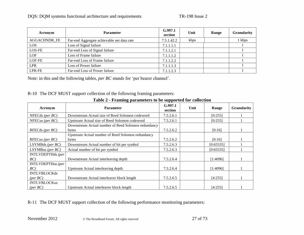
R-10 The DCF MUST support collection of the following framing parameters:
Table 2 - Framing parameters to be supported for collection
Acronym Parameter G.997.1
section Unit Range Granularity
NFECds (per BC) Downstream Actual size of Reed Solomon codeword 7.5.2.6.1 [0:255] 1
NFECus (per BC) Upstream Actual size of Reed Solomon codeword 7.5.2.6.1 [0:255] 1
RFECds (per BC)
Downstream Actual number of Reed Solomon redundancy
bytes 7.5.2.6.2
[0:16] 1
RFECus (per BC)
Upstream Actual number of Reed Solomon redundancy
bytes 7.5.2.6.2
[0:16] 1
LSYMBds (per BC) Downstream Actual number of bit per symbol 7.5.2.6.3 [0:65535] 1
LSYMBus (per BC) Actual number of bit per symbol 7.5.2.6.3 [0:65535] 1
INTLVDEPTHds (per
BC) Downstream Actual interleaving depth 7.5.2.6.4
[1:4096] 1
INTLVDEPTHus (per
BC) Upstream Actual interleaving depth 7.5.2.6.4
[1:4096] 1
INTLVBLOCKds
(per BC) Downstream Actual interleaver block length 7.5.2.6.5
[4:255] 1
INTLVBLOCKus
(per BC) Upstream Actual interleaver block length 7.5.2.6.5
[4:255] 1
R-11 The DCF MUST support collection of the following performance monitoring parameters:

DQS: DQM systems functional architecture and requirements TR-198 Issue 2
November 2012 © The Broadband Forum. All rights reserved 28 of 73
Table 3 - Performance monitoring parameters to be supported for collection
Acronym Parameter G.997.1
section Unit Range Granularity
ES-L Errored Seconds – Line 7.2.1.1.2 1
ES-LFE Errored Seconds – Line far-end 7.2.1.2.2 1
SES-L Severely Errored Seconds – Line 7.2.1.1.3 1
SES-LFE Severely Errored Seconds – Line far-end 7.2.1.2.3 1
LOSS-L Loss of Signal Seconds – Line 7.2.1.1.4 1
LOSS-LFE Loss of Signal Seconds – Line far-end 7.2.1.2.4 1
UAS-L Unavailable Seconds – Line 7.2.1.1.5 1
UAS LFE Unavailable Seconds – Line far-end 7.2.1.2.5 1
FECS-L Forward Error Corrections Seconds Line 7.2.1.1.1 1
FECS-LFE Forward Error Corrections Seconds Line Far End 7.2.1.2.1 1
FULLINIT Full initialization count 7.2.1.3.1 1
FAILINIT Failed full initialization count 7.2.1.3.2 1
SHORTINIT Short initialization count 7.2.1.3.3 1
FAILSHORTINIT Failed short initialization count 7.2.1.3.4 1
INMINPEQ1..17-L INM INPEQ histogram 1..17 7.2.1.4.1 1
INMME-L INM total measurement 7.2.1.4.2 1
INMIAT0..7-L INM IAT histogram 0..7 7.2.1.4.3 1
INMINPEQ1..17-LFE INM INPEQ histogram 1..17 7.2.1.5.1 1
INMME-LFE INM total measurement 7.2.1.5.2 1
INMIAT0..7-LFE INM IAT histogram 0..7 7.2.1.5.3 1
SOS-SUCCESS-NE Near-end successful SOS count 7.2.1.6.1 1
SOS-SUCCESS-FE Far-end successful SOS count 7.2.1.7.1 1
LPR_INTRPT Loss-of-power interruption count 7.2.1.8.1 1
HRI_INTRPT Host-Reinit interruption count 7.2.1.8.2 1
SPONT_INTRPT Spontaneous interruption count 7.2.1.8.3 1
CV-C Code Violations – Channel 7.2.2.1.1 1
CV-CFE Code Violations – Channel far-end 7.2.2.2.1 1
FEC-C Forward Error Corrections – Channel 7.2.2.1.2 1
FEC-CFE Forward Error Corrections – Channel far-end 7.2.2.2.2 1
CRC-P Near-end CRC error count 7.2.5.1.1 1
CRC-PFE Far-end CRC error count 7.2.5.2.1 1
CV-P Near-end coding violations count 7.2.5.1.2 1

DQS: DQM systems functional architecture and requirements TR-198 Issue 2
November 2012 © The Broadband Forum. All rights reserved 29 of 73
Acronym Parameter G.997.1
section Unit Range Granularity
CV-PFE Far-end coding violations count 7.2.5.2.2 1
LINIT Line initialization failure 7.1.1.3 1
LeftrDS-L ‘leftr” defects seconds counter 7.2.1.1.6 1
LeftrDS-LFE ‘leftr” defects seconds counter 7.2.1.2.6 1
EBC-L Errorfree bits Counter 7.2.1.1.7 1
EBC-LFE Errorfree bits Counter 7.2.1.2.7 1
MINEFTR-L Near-end minimum error-free throughput (only US) 7.2.1.1.8 bit/s
MINEFTR-LFE Far-end minimum error-free throughput (only DS) 7.2.1.2.8 bit/s
R-12 The DCF MUST support collection of the following vectorial parameters:
Table 4 - Vectorial parameters to be supported for collection
Acronym Parameter G.997.1
section Unit Range Granularity
HLOGGds Downstream H(f) logarithmic subcarrier group size 7.5.1.26.5 1-2-4-8 1
HLOGpsds Downstream H(f) logarithmic representation 7.5.1.26.6 dB [-96.3 ÷ 6.0] 0.1
HLOGGus Upstream H(f) logarithmic subcarrier group size 7.5.1.26.11 1-2-4-8 1
HLOGpsus Upstream H(f) logarithmic representation 7.5.1.26.12 dB [-96.3 ÷ 6.0] 0.1
QLNGds Downstream QLN(f) subcarrier group size 7.5.1.27.2 1-2-4-8 1
QLNpsds Downstream QLN(f) 7.5.1.27.3 dbm/Hz [-150.0 ÷ -23.0] 0.5
QLNGus Upstream QLN(f) subcarrier group size 7.5.1.27.5 1-2-4-8 1
QLNpsus Upstream QLN(f) 7.5.1.27.6 dbm/Hz [-150.0 ÷ -23.0] 0.5
SNRGds Downstream SNR(f) subcarrier group size 7.5.1.28.2 1-2-4-8 1
SNRpsds Downstream SNR(f) 7.5.1.28.3 dB [-32.0 ÷ 95.0] 0.5
SNRGus Upstream SNR(f) subcarrier group size 7.5.1.28.5 1-2-4-8 1
SNRpsus Upstream SNR(f) 7.5.1.28.6 dB [-32.0 ÷ 95.0] 0.5
BITSpsds Downstream Bits Allocation 7.5.1.29.1 [0 ÷ 15] 1
BITSpsus Upstream Bits Allocation 7.5.1.29.2 [0 ÷ 15] 1
GAINSpsds Downstream Gains Allocation 7.5.1.29.3 [0 ÷ 4095] 1
GAINSpsus Upstream Gains Allocation 7.5.1.29.4 [0 ÷ 4095] 1
MREFPSDds Downstream MEDLEY Reference PSD 7.5.1.29.7 see G.993.2
MREFPSDus Upstream MEDLEY reference PSD 7.5.1.29.8 see G.993.2

DQS: DQM systems functional architecture and requirements TR-198 Issue 2
November 2012 © The Broadband Forum. All rights reserved 30 of 73
Acronym Parameter G.997.1
section Unit Range Granularity
XLINSCds Downstream XLIN scale 7.5.1.38.1 dB [1-2^16-1] 1
XLINSCus Upstream XLIN scale 7.5.1.39.5 [1-2^16-1] 1
XLINGds Downstream XLIN subcarrier group size 7.5.1.38.2 [1, 2, 4,
8,16,32,64] 1
XLINGus Upstream XLIN subcarrier group size 7.5.1.39.6 [1, 2, 4,
8,16,32,64] 1
XLINBANDSds Downstream XLIN bandedges 7.5.1.39.3 [0 ÷ 4095] 1
XLINBANDSus Upstream XLIN bandedges 7.5.1.39.7 [0 ÷ 4095] 1
XLINpsds Downstream FEXT coupling 7.5.1.39.4 [-2^15 ÷ +2^15] 1
XLINpsus Upstream FEXT coupling 7.5.1.39.8 [-2^15 ÷ +2^15] 1
R-13 The DCF MUST support collection of the following status parameters:
Table 5 - Status parameters to be supported for collection
Acronym Parameter G.997.1
section Unit Range Granularity

DQS: DQM systems functional architecture and requirements TR-198 Issue 2
November 2012 © The Broadband Forum. All rights reserved 31 of 73
LINKSTATUS Link Status (i.e. showtime, training, down, etc) N/A
XTSU xDSL transmission system in use 7.5.1.1
VDSL2-PROF VDSL2 profile in use 7.5.1.2
VDSL2-PSD&BPLAN VDSL2 limit PSD mask and band plan in use 7.5.1.3
VDSL2-US0MASK VDSL2 US0 PSD Mask in use 7.5.1.4
POWERSTATE Line power management state 7.5.1.5 [0:3]
INIT_SUCCESS/FAIL_CA
USE Initialization Success/Failure cause 7.5.1.6
[0 ÷ 6] 1
DS_LAST_STATE_TX
Last state transmitted downstream 7.5.1.7
See
individual
recommendat
ions
US_LAST_STATE_TX
Last state transmitted upstream 7.5.1.8
See
individual
recommendat
ions
adslAtucCurrStatus adslAtucCurrStatus
N/A
RFC 2662
[10]
Xdsl2LineStatusXtu Xdsl2LineStatusXtu
N/A
RFC 5650
[15]

DQS: DQM systems functional architecture and requirements TR-198 Issue 2
November 2012 © The Broadband Forum. All rights reserved 32 of 73
R-14 The DCF MUST support collection of the following xTU info parameters:
Table 6 - xTU info parameters to be supported for collection
Acronym Parameter G.997.1
section Unit Range Granularity
xTU-C-CHIPVID xTU-C G.994.1 Vendor ID 7.4.1 see G.994.1
xTU-R-CHIPVID xTU-R G.994.1 Vendor ID 7.4.2 see G.994.1
xTU-C-SYSVID xTU-C System Vendor ID 7.4.3 see G.994.1
xTU-R-SYSVID xTU-R System Vendor ID 7.4.4 see G.994.1
xTU-C-VERNUM xTU-C version number 7.4.5
xTU-R-VERNUM xTU-R version number 7.4.6
xTU-C-SERNUM xTU-C serial number 7.4.7
xTU-R-SERNUM xTU-R serial number 7.4.8
xTU-C self test result xTU-C self test result 7.4.9
xTU-R self test result xTU-R self test result 7.4.10
xTU-C transmission system
capabilities xTU-C transmission system capabilities 7.4.11
[0 ÷
FFFFFFFF]
1
xTU-R transmission system
capabilities xTU-R transmission system capabilities 7.4.12
[0 ÷
FFFFFFFF]
1
VCE_ID VCE_ID 7.4.13.1
VCE_port_index VCE port index 7.4.13.2
R-15 The DCF MUST support collection of the following ‘Vector of Profiles’ parameters, if supported by the DQM-ME:
Table 7 - Vector of Profiles parameters to be supported for collection
Acronym Parameter TR-252
section
LCONF-VECT Line Configuration Vector 5.4
DRds-PROF DS Data Rate Profile 5.5
DRus-PROF US Data Rate Profile 5.5
SPECT-PROF Line Spectrum Profile 5.6
MSPSD-PROF Mode Specific PSD Profile 5.6
DPBO-PROF DPBO Profile 5.6
UPBO-PROF UPBO Profile 5.6
RFI-PROF RFI Profile 5.6

DQS: DQM systems functional architecture and requirements TR-198 Issue 2
November 2012 © The Broadband Forum. All rights reserved 33 of 73
Acronym Parameter TR-252
section
VECT-PROF Vectoring Profile 5.7
SNR-PROF SNR Margin Profile 5.7
INPDEL-PROF INP-Delay Profile 5.7
VN-PROF Virtual Noise Profile 5.7
SOS-PROF SOS Profile 5.7
INM-PROF INM Profile 5.7
DQS: DQM systems functional architecture and requirements TR-198 Issue 2
November 2012 © The Broadband Forum. All rights reserved 34 of 73
The inventory parameters refer to the Network Element (NE) which supports the DSL Service, e.g. a
DSLAM or Access Node (AN). As the structure of inventory information for DSL Network Elements
is specific to the architecture of the NE as implemented by the manufacturer the requirements related
to collection of inventory information MUST take into account these implementation specific
differences. Additionally since the structure of the inventory information occurs in entities that can
contain multiple DSL transceivers and thus is inherently ‘above’ the level of management of the DSL
transceiver, the definition of the management objects is not part of the object definitions provided in
DSL standards such as G.997.1 [23], or the IETF xDSL MIBs. The following generic requirements
define the inventory requirements for a DSL NE, i.e. a DSL AN or DSLAM.
R-16 It MUST be possible to query the NE to obtain a list of all DSLAM ports, line cards, shelves,
etc., where the identification of the component corresponds to the equipment hierarchy
inherent in the design of the NE. For example a DSLAM which is organized into shelf, line
card, and port would identify the DSLAM port by the hierarchy of DSLAM ID, Shelf ID,
Line Card ID, Port ID.
Note: An equipment hierarchy that meets the criteria defined in Telcordia TR GR-831 [27] or the
TMF MTOSIv2 [28] for equipment hierarchy provides a suitable identification hierarchy. However,
the specifics of the identification hierarchy are vendor dependent.
R-17 It MUST be possible to query the administrative and operational states of any or all DSL
ports or high level entities (e.g. line cards, shelves). As a minimum valid administrative states
MUST include: Enabled, Disabled. As a minimum valid operational states MUST include:
xDSL Service Up, xDSL Service Down.
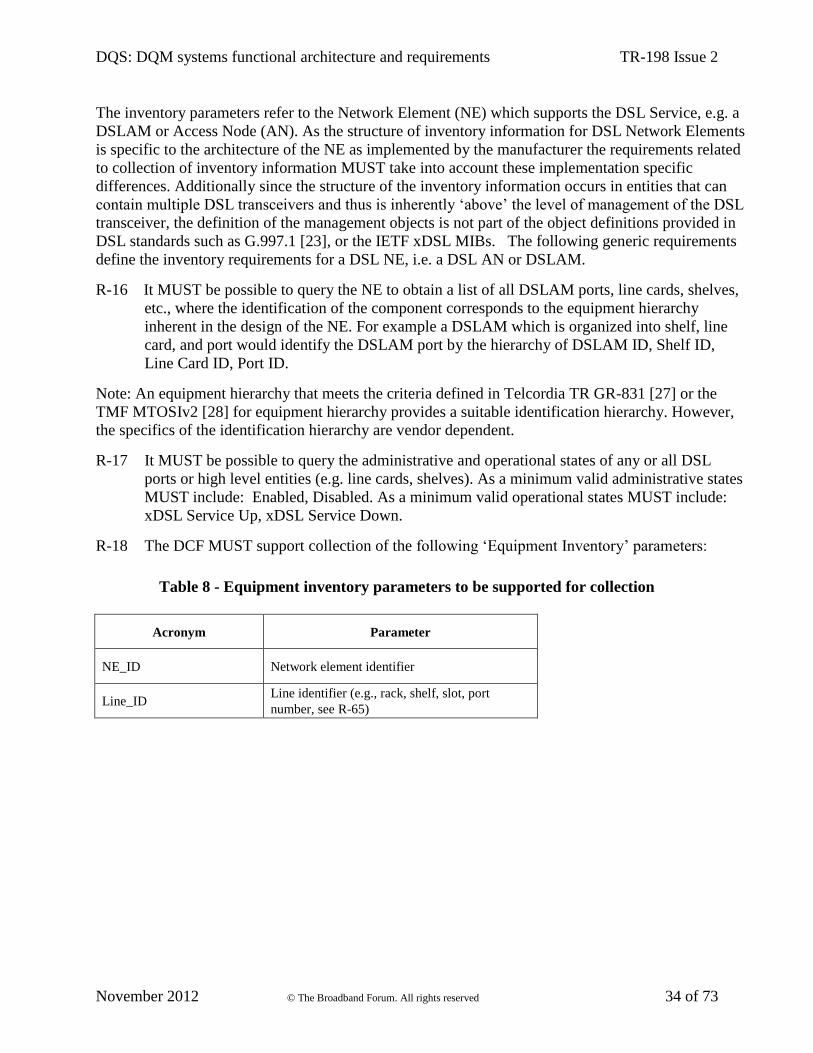
R-18 The DCF MUST support collection of the following ‘Equipment Inventory’ parameters:
Table 8 - Equipment inventory parameters to be supported for collection
Acronym Parameter
NE_ID Network element identifier
Line_ID Line identifier (e.g., rack, shelf, slot, port
number, see R-65)
DQS: DQM systems functional architecture and requirements TR-198 Issue 2
November 2012 © The Broadband Forum. All rights reserved 35 of 73
R-19 The industry standards and practices listed in Section 5.1, interface B with respect to
inventory SHOULD be used as the basis for these parameters.
6.1.2 Collected DSL Related Notifications
This section specifies the requirements about collection of the DSL related notifications
generated by the DQM-ME upon crossing of the associated performance monitoring thresholds.
Those notifications associated to performance monitoring thresholds MUST be all specified per
15-minute and per 24-hour intervals.
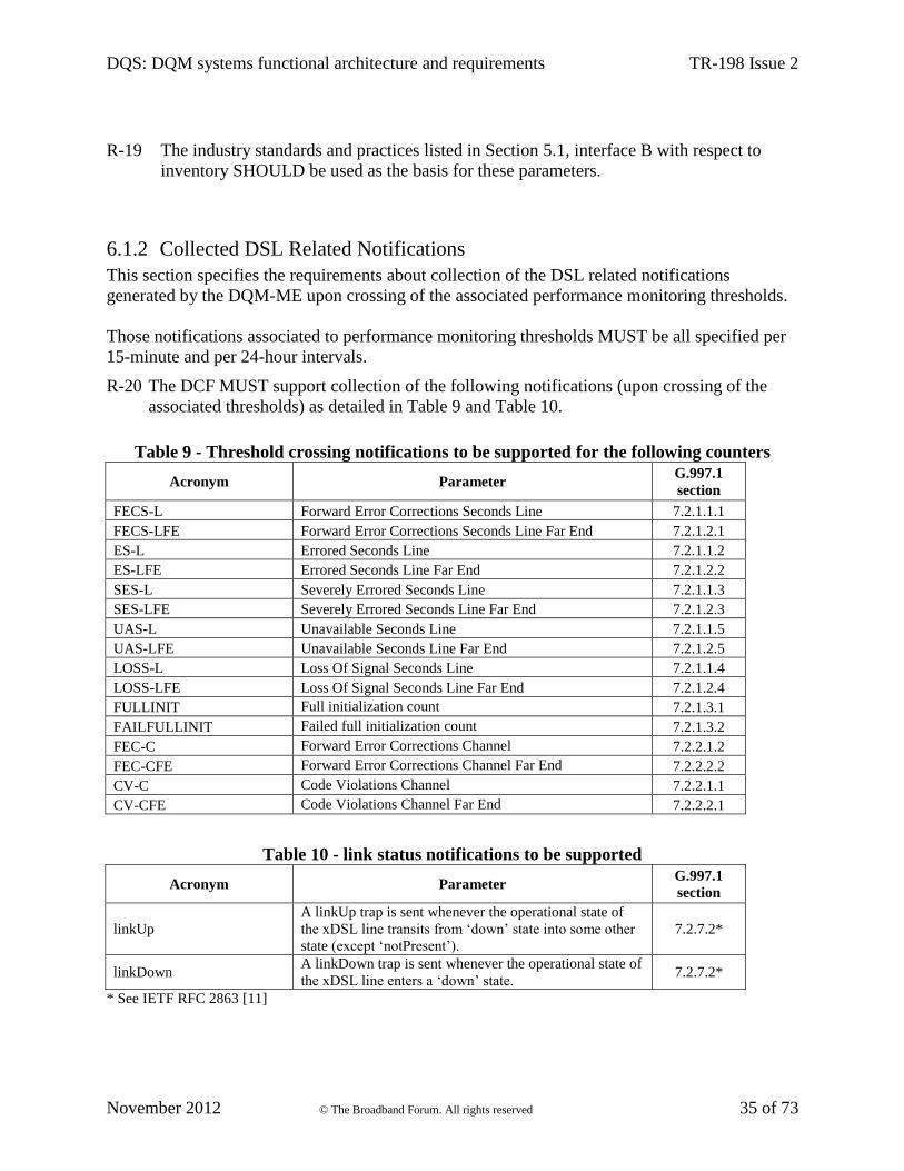
R-20 The DCF MUST support collection of the following notifications (upon crossing of the
associated thresholds) as detailed in Table 9 and Table 10.
Table 9 - Threshold crossing notifications to be supported for the following counters
Acronym Parameter G.997.1
section
FECS-L Forward Error Corrections Seconds Line 7.2.1.1.1
FECS-LFE Forward Error Corrections Seconds Line Far End 7.2.1.2.1
ES-L Errored Seconds Line 7.2.1.1.2
ES-LFE Errored Seconds Line Far End 7.2.1.2.2
SES-L Severely Errored Seconds Line 7.2.1.1.3
SES-LFE Severely Errored Seconds Line Far End 7.2.1.2.3
UAS-L Unavailable Seconds Line 7.2.1.1.5
UAS-LFE Unavailable Seconds Line Far End 7.2.1.2.5
LOSS-L Loss Of Signal Seconds Line 7.2.1.1.4
LOSS-LFE Loss Of Signal Seconds Line Far End 7.2.1.2.4
FULLINIT Full initialization count 7.2.1.3.1
FAILFULLINIT Failed full initialization count 7.2.1.3.2
FEC-C Forward Error Corrections Channel 7.2.2.1.2
FEC-CFE Forward Error Corrections Channel Far End 7.2.2.2.2
CV-C Code Violations Channel 7.2.2.1.1
CV-CFE Code Violations Channel Far End 7.2.2.2.1
Table 10 - link status notifications to be supported
Acronym Parameter G.997.1
section
linkUp
A linkUp trap is sent whenever the operational state of
the xDSL line transits from ‘down’ state into some other
state (except ‘notPresent’).
7.2.7.2*
linkDown A linkDown trap is sent whenever the operational state of
the xDSL line enters a ‘down’ state. 7.2.7.2*
* See IETF RFC 2863 [11]

DQS: DQM systems functional architecture and requirements TR-198 Issue 2
November 2012 © The Broadband Forum. All rights reserved 36 of 73
6.2 Data Collection Function Implementation
The Data Collection Function (DCF) is implemented as shown in Figure 2. The functional units
depicted can be sited as either separate entities or within the same physical entity and some
example configurations are shown in Appendix C. The DCF retrieves data from the DQM-MEs
of network elements (NEs) through the DCF Southbound Interface as defined in Section 6.4. The
DCF provides the collected data to the ADF (or other functional entities) through the DCF
Northbound Interface as defined in Section 6.3.
ADF DCF DQM-MEDCF
N/B i/f
DCF
S/B i/f
Figure 2 - Data Collection Function
6.3 Data Collection Function “Northbound” Interface
The Data Collection Function Northbound interface is denoted “G” in the Figure 1.
R-21 The requirements in this section MUST be implemented at the interface between the ADF
and the DCF, if the DCF is not implemented in the same physical entity as the ADF. If the
DCF is integrated in the same physical entity as the ADF, its Northbound interface would
be internal to the physical entity and outside the scope of TR-198.
6.3.1 Interface Primitives
The DCF Northbound interface consists of an exchange of primitives between the ADF (or
several ADFs or other functional entities) and the DCF. In the rest of this section the ADF is
always mentioned as the counterpart entity communicating with the DCF via its Northbound
interface. Nevertheless a DCF MUST be able to interface with several ADFs or other functional
entities. Primitives are listed in Table 11, with the related information fields carried by each
primitive. ‘Request’ primitives are sent from the ADF to the DCF. ‘Confirm’ primitives are sent
from the DCF to the ADF in immediate response to a request primitive. ‘Indicate’ primitives are
sent autonomously from the DCF to the ADF.
Table 11 - Interface Primitives and Information Fields
Bulk collection
Create_collection_task.request (task_name,resource_list,
{parameter_list,collection_frequency,upload_frequency},
collection_filter, task_duration, priority_request_flag)
Create_collection_task.confirm (task_ID, errorcode)
Retrieve_collection_task_info.request (task_ID) Retrieve_ collection_task_info.confirm (task_ID,
task_status, task_name,resource_list,
{parameter_list,collection_frequency,
DQS: DQM systems functional architecture and requirements TR-198 Issue 2
November 2012 © The Broadband Forum. All rights reserved 37 of 73
upload_frequency}, collection_filter, task_duration,
priority_request_flag, errorcode)
Modify_collection_task.request (task_ID, resource_list,
{parameter_list, collection_frequency,
upload_frequency}, collection_filter, task_duration,
priority_request_flag)
Modify_collection_task.confirm (task_ID, errorcode)
Retrieve_all_collection_tasks.request () Retrieve_all_collection_tasks.confirm ({task_ID,
task_status}, errorcode)
Retrieve_all_active_collection_tasks.request () Retrieve_all_active_collection_tasks.confirm ({task_ID},
errorcode)
Delete_collection_task.request (task_ID) Delete_collection_task.confirm (task_ID, errorcode)
Start_collection_task.request (task_ID) Start_collection_task.confirm (task_ID, errorcode)
Stop_collection_task.request (task_ID) Stop_collection_task.confirm (task_ID, errorcode)
Reporting
Report_upload.request(task_ID) Report_upload.confirm(task_ID, report, errorcode)
--- Report_upload.indicate(task_ID, report, errorcode)
Report_delete.request(task_ID) Report_delete.confirm(task_ID, errorcode)
NOTE 1 – {xyz} denotes a set of xyz.
6.3.1.1 Create_collection_task Primitives
R-22 The DCF MUST support the create_collection_task.request primitive, with Information
Fields as defined in Table 12. Upon receiving this primitive, the DCF MUST create a
data collection task, initialize the task’s parameters according to the received Information
Fields and allocate a task_ID for it with initial task status set to ‘inactive’.
Table 12 - Create_collection_task primitive configurable parameters
Parameter Description and behaviour
task_name Name of the collection task according to the syntax specified in R-63
resource_list List of resources from which data are collected. See also R-32.
As a minimum, this list MUST be implemented down to a line-level
granularity, i.e.:
resource_list = {NE_ID, {line_ID}}
Each resource in the list is specified according to the syntax in R-65.
DQS: DQM systems functional architecture and requirements TR-198 Issue 2
November 2012 © The Broadband Forum. All rights reserved 38 of 73
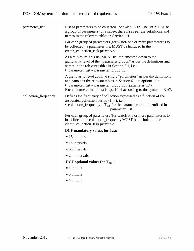
parameter_list List of parameters to be collected. See also R-32. The list MUST be
a group of parameters (or a subset thereof) as per the definitions and
names in the relevant tables in Section 6.1.
For each group of parameters (for which one or more parameter is to
be collected), a parameter_list MUST be included in the
create_collection_task primitive.
As a minimum, this list MUST be implemented down to the
granularity level of the “parameter groups” as per the definitions and
names in the relevant tables in Section 6.1, i.e.:
parameter_list = parameter_group_ID
A granularity level down to single “parameters” as per the definitions
and names in the relevant tables in Section 6.1, is optional, i.e.:
parameter_list = parameter_group_ID,{parameter_ID}
Each parameter in the list is specified according to the syntax in R-67.
collection_frequency Defines the frequency of collection expressed as a function of the
associated collection period (Tcoll), i.e.:
collection_frequency = Tcoll for the parameter group identified in
parameter_list
For each group of parameters (for which one or more parameter is to
be collected), a collection_frequency MUST be included in the
create_collection_task primitive.
DCF mandatory values for Tcoll:
15 minutes
1h intervals
6h intervals
24h intervals
DCF optional values for Tcoll:
1 minute
3 minute
5 minute

DQS: DQM systems functional architecture and requirements TR-198 Issue 2
November 2012 © The Broadband Forum. All rights reserved 39 of 73
upload_frequency Defines the frequency of uploads expressed as a function of the
associated upload period (Tupload), i.e.:
upload_frequency = Tupload for the related parameter group
identified in parameter_list
For each group of parameters (for which one or more parameters are
to be collected), an upload_frequency MUST be included in the
create_collection_task primitive.
The value of the Tupload configured for a certain “group parameters”
MUST be a multiple of the correspondent Tcoll: Tupload_param_group = N *
Tcoll_param_group (N being an integer).
DCF mandatory values for Tupload: N * Tcoll., with N integer in the
range from 1 to 100.
An optional special value is defined for Tupload meaning no automatic
upload, hence data retrieval is expected to be done asynchronously
via report_upload.request primitive.
collection_filter Introduces a filter over the set of resources listed in resource_list. The
value of this parameter MUST be dynamically recalculated once for
every collection period configured in collection_frequency.
The collection_filter MUST be expressed as a logical combination of
boolean equations on the parameters listed in Section 6.1.
If filter holds TRUE, data MUST be collected
If filter holds FALSE: data MUST not be collected
DCF mandatory filters:
As a minimum the following two filters about line defect status
MUST be supported:
(adslAtucCurrStatus = ‘noDefect’) (for ADSL lines),
(xdsl2LineStatusXtuc = ‘noDefect’) (for ADSL/2/2plus and
VDSL2 lines)
Note: adslAtucCurrStatus specified as per RFC 2662 [10];
xdsl2LineStatusXtuc specified as per RFC 5650 [15].
DCF optional filters:
Other logical combinations of boolean equations on the parameters
listed in Section 6.1 are optional, e.g.;
(SNRMus < 6 dB)&( CV-C > 3);
(ADRds > 20 Mbps).

DQS: DQM systems functional architecture and requirements TR-198 Issue 2
November 2012 © The Broadband Forum. All rights reserved 40 of 73
task_duration Overall duration time of the collection task.
The value of task duration MUST not be lower than the highest
configured Tupload and MUST be an integer multiple of such value.
DCF mandatory values: N * the highest configured Tupload , with N
integer in the range from 1 to 100.
Priority_request_flag Boolean value to indicate if flag is set or not.
TRUE: High priority has been requested.
FALSE: Normal priority has been requested. FALSE is the
default value
Procedures to enforce this flag are optional in the DCF and the DCF
MAY implement procedures to enforce this primitive. Details of the
implementation of behaviours related to this flag in the DCF are
outside the scope of TR-198.
R-23 The DCF MUST acknowledge a create_collection_task.request primitive with a
create_collection_task.confirm primitive. The create_collection_task.confirm primitive
MUST contain the parameters defined in Table 13 and their specified behaviour:
Table 13 - Create_collection_task.request primitive parameters
Parameter Description and behaviour
task_id The unique identifier of the collection task according to the syntax
specified in R-64.
task_status The status of the collection task that its identifier is given by task_ID
errorcode The errorcode will be defined according to the requirement defined in
R-66.
6.3.1.2 Modify_collection_task Primitives
R-24 The DCF MUST support the modify_collection_task.request primitive, with Information
Fields containing the task_ID plus any of the parameters defined in Table 11. All task
parameters can be modified with the exception of the task_name. Upon receiving this
primitive, if the collection task identified by Task_ID is in inactive status, the DCF
MUST modify the requested parameters. If the task is active, no modification MUST be
accepted.
R-25 The DCF MUST acknowledge a modify_collection_task.request primitive, upon
receiving it, with a modify_collection_task.confirm primitive. The
modify_collection_task.confirm primitive MUST contain the task_ID and an errorcode to
indicate the success or failure (including cause of failure) of the request execution.

DQS: DQM systems functional architecture and requirements TR-198 Issue 2
November 2012 © The Broadband Forum. All rights reserved 41 of 73
6.3.1.3 Start_collection_task Primitives
R-26 The DCF MUST support the start_collection_task.request primitive. Upon receiving this
primitive, the DCF MUST start the collection task identified by Task_ID and change the
task status to active if the DCF has sufficient resources to start the task. Otherwise the
task MUST not be started and the task status MUST remain inactive.
R-27 The DCF MUST acknowledge a start_collection_task.request primitive, upon receiving
it, with a start_collection_task.confirm primitive. The start_collection_task.confirm
primitive MUST contain the task_ID and an errorcode to indicate the success or failure
(including cause of failure) of the request execution.
R-28 If the DCF is not integrated in a network element, it MUST be able to create and start
collection tasks involving data collection from multiple network elements.
R-29 The DCF MUST support independent start of collection tasks.
R-30 The DCF MUST support multiple collection tasks to be simultaneously in the active
status.
R-31 While the collection task status is active, the DCF MUST collect the parameters
identified by the set of parameter_IDs.
R-32 While the collection task status is active, the DCF MUST collect all the parameters
indicated in all the parameter_list instances from all the resources indicated in the
resource_list.
R-33 While the collection task status is active, the DCF MUST poll the DQM-ME for the
requested parameter(s) with an interval as specified by the collection_frequency.
R-34 While the collection task status is active, the DCF MUST perform the first collection
within the collection period following the next time the wall clock passes the boundary of
an interval that is part of the collection_frequency. The interval boundaries are either
midnight for the daily collection, one of the quarters of a day for 6-hour collection, the
hour for the hourly collection and one of the quarters for 15 minute collection.
NOTE: For example, if the current time is 14h32, a newly activated 15 minute collection will take place
between 14h45 and 15h00, while a newly activated hourly collection will only start after 15h00 and a
daily collection only after 00h00.
R-35 The DCF MUST make sure that the period between the start of consecutive collections is
always as close to identical as possible.
NOTE: This means that a collection will always take place at the same time offset relative to the start of
the interval. For example, if a 15 minute collection takes place at 15h07, then it will reoccur at 15h22,
15h37, 15h52, etc.

DQS: DQM systems functional architecture and requirements TR-198 Issue 2
November 2012 © The Broadband Forum. All rights reserved 42 of 73
6.3.1.4 Stop_collection_task Primitives
R-36 The DCF MUST support the stop_collection_task.request primitive. Upon receiving this
primitive, the DCF MUST stop the collection task identified by Task_ID and change the
task status to inactive at the end of current 15-minute interval, as aligned with the
network/NE absolute time.
R-37 The DCF MUST acknowledge a stop_collection_task.request primitive, upon receiving
it, with a stop_collection_task.confirm primitive. The stop_collection_task.confirm
primitive MUST contain the task_ID and an errorcode to indicate the success or failure
(including cause of failure) of the request execution.
R-38 When the collection task status is set to inactive, the DCF MUST stop collecting
parameters from the NE.
R-39 Inactive tasks MUST be reported in the retrieve_all_collection_tasks.confirm primitive.
R-40 The DCF MUST support independent stop of collection tasks.
6.3.1.5 Retrieve_collection_tasks Primitives
R-41 The DCF MUST acknowledge a retrieve_collection_task_info.request primitive with a
retrieve_collection_task_info.confirm primitive. The
retrieve_collection_task_info.confirm primitive MUST contain the task_ID, task_status,
the task’s configuration parameters and an errorcode to indicate the success or failure
(including cause of failure) of the request execution.
R-42 The DCF MUST acknowledge a retrieve_all_collection_tasks.request primitive with a
retrieve_all_collection_tasks.confirm primitive. The
retrieve_all_collection_tasks.confirm primitive MUST contain a list of the collection
tasks (and their related status) in the DCF and an errorcode to indicate the success or
failure (including cause of failure) of the request execution.
R-43 The DCF MUST acknowledge a retrieve_active_collection_tasks.request primitive with
a retrieve_active_collection_tasks.confirm primitive. The
retrieve_active_collection_tasks.confirm primitive MUST contain a list of the active
collection tasks in the DCF and an errorcode to indicate the success or failure (including
cause of failure) of the request execution.
6.3.1.6 Delete_collection_task Primitives
R-44 The DCF MUST support the delete_collection_task.request primitive. Upon receiving
this primitive, the DCF MUST delete the task identified by task_ID from its tasks list.
When a task is deleted, the associated configuration parameters, task status and reports
are deleted in the DCF.

DQS: DQM systems functional architecture and requirements TR-198 Issue 2
November 2012 © The Broadband Forum. All rights reserved 43 of 73
R-45 The DCF MUST acknowledge a delete_collection_task.request primitive, upon receiving
it, with a delete_collection_task.confirm primitive. The delete_collection_task.confirm
primitive MUST contain the task_ID and an errorcode to indicate the success or failure
(including cause of failure) of the request execution.
R-46 The DCF MUST support independent deletion of collection tasks.
6.3.1.7 Reporting Primitives
R-47 The DCF MUST NOT delete data that is included in the report_upload.confirm primitive
until after automatic upload is successfully performed.
R-48 For each collection task the DCF MUST create a report of the collected parameters
containing the following:
timestamp uniquely identifies the time instant of collection. Every collected
parameter value MUST be traceable back to a timestamp.
incomplete_flag identifies that the sample data associated to a collection period is
incomplete for any reason. One single incomplete_flag is sufficient per each
report.
Per each parameter the following data MUST be contained in the Report:
resource_ID uniquely identifies the collection resource on which the parameter
has been collected.
The parameter_ID uniquely identifies the parameter that has been collected as
per the definitions and names in the relevant tables in Section 6.1
parameter_value is the retrieved value of the parameter that has been collected.
The above bullet list defines the information content of the report and does not mandate
any specific syntax. Syntax is for further study.
The resource_ID is defined in R-65.
R-49 The DCF MUST support the report_upload.request primitive for pull-upload (i.e., report
retrieved by the OSS or a centralized server from the DCF) of collection task reports.
Upon receiving this primitive.
R-50 The DCF MUST upload the report associated with the task_ID to the OSS or a central
server.
R-51 The report_upload.request MUST be possible even if an automatic report upload has
been configured (i.e. when the upload_frequency parameter is different from the optional
special value).
R-52 The DCF MUST acknowledge a report_upload.request primitive with a
report_upload.confirm primitive. The report_upload.confirm primitive MUST contain

DQS: DQM systems functional architecture and requirements TR-198 Issue 2
November 2012 © The Broadband Forum. All rights reserved 44 of 73
the task_ID, the associated report and an errorcode to indicate the success or failure
(including cause of failure) of the request execution.
R-53 The DCF MUST support the report_upload.indicate primitive for push-upload (i.e.,
report autonomously sent by DCF to the OSS or a centralized server) of collection task
reports. This primitive MUST contain the task_ID, the associated report and an errorcode
to indicate the success or failure (including cause of failure) of the request execution.
R-54 The DCF MUST autonomously send a report_upload.indicate primitive at the end of
every upload period, as per the configured upload_frequency parameter.
R-55 The DCF SHOULD support report deletion after an automatic upload is successfully
performed.
R-56 The DCF MUST support the report_delete.request primitive. Upon receiving this
primitive, the DCF MUST delete from the report associated with the Task_ID, all
collected data up to last 15-minute interval. The task status MUST not be changed (i.e., if
currently active, the task MUST continue to collect data).
R-57 The DCF MUST acknowledge a report_delete.request primitive with a
report_delete.confirm primitive. The report_delete.confirm primitive MUST contain the
task_ID and an errorcode to indicate the success or failure (including cause of failure) of
the request execution.
6.3.1.8 Task duration
R-58 Upon expiry of the duration of a collection task, the DCF MUST change its status to
completed. In this status, the collection task cannot be restarted nor modified in any way.
R-59 When the collection task status becomes completed, the DCF MUST stop collecting
parameters from the NE.
R-60 Completed tasks MUST be reported in the retrieve_all_collection_tasks.confirm
primitive.
R-61 The DCF MUST NOT autonomously delete the collected data when a task goes into
completed status, except for the normal deletion procedure when an automatic data
upload is successfully performed.
6.3.2 Format of the Information Fields
R-62 The syntax of the timestamp information fields MUST be either the number of seconds
since 1 January 1970 (UNIX time) or alphanumeric in “DDMMYYYY-HHMMSS”
format.
R-63 The task_name MUST be an ASCII string of up to 128 characters.

DQS: DQM systems functional architecture and requirements TR-198 Issue 2
November 2012 © The Broadband Forum. All rights reserved 45 of 73
R-64 The task_ID MUST be a 32-bit unsigned integer.
R-65 The resource_ID MUST be a string that identifies each DSL port by its hierarchy, that is,
by specifying the associated NE_ID (network element) and line_ID (e.g. rack, shelf, slot
and port number).
NOTE: For example, for the resource AB_IPDSLAM103, rack=1, shelf=1, slot=3, port=25, the
resource_ID string could be: “AB_IPDSLAM103-001-001-003-025”.
R-66 The errorcode MUST be a 32-bit unsigned integer. One value MUST indicate that the
execution was successful while all other values indicate that the execution failed.
R-67 The format of the parameter_ID information field MUST be an alphanumeric string that
uniquely identifies the parameter according to the parameter names in Section 6.1.
R-68 The parameter_value information field MUST be formatted as relevant for the type of
object that is requested.
6.3.3 Interface Protocol
The interface protocol to transport the primitives and their information fields is outside the scope
of TR-198.
6.4 Data Collection Function “Southbound” Interface
The Data Collection Function Southbound interface is denoted “A” and “B” in the Figure 1.
R-69 The requirements in this section MUST be implemented at the interface between the
DCF and the DQM-ME, if the DCF is not in the same physical entity as the DQM-ME.
The requirements apply regardless of the DCF being implemented in the same physical
entity as the ADF or in a physical entity separate from the ADF.
If the DCF is in the same physical entity as the DQM-ME, its Southbound interface is outside the
scope of TR-198.
R-70 This interface MUST allow the DCF to access the parameters listed in Section 6.1 in the
DQM-ME. Refer to G.997.1 [23], TR-252 [7], for the list of managed objects and the
profiling of configuration parameters.
R-71 The underlying protocol MAY be SNMP, XML or another protocol.
R-72 If the underlying protocol is SNMP, The DCF should provide access to the parameters,
listed in section 6.1, as managed objects as described in the MIB modules.

DQS: DQM systems functional architecture and requirements TR-198 Issue 2
November 2012 © The Broadband Forum. All rights reserved 46 of 73
6.5 DCF Performance Requirements
This section specifies the minimum DCF performance requirements in terms of the aggregate
processing/memory/data-transfer capabilities necessary to support the referenced combined data
collection task given below in the table in R-73. The referenced combined data collection task
applies only with respect to the scope of the performance requirements in this section and has
been defined with the purpose of identifying a minimum conventional load that the DCF ought to
be able to support. The collection and upload frequency values indicated below do not supersede
the requirements for collection and upload frequency in R-23.
The concept of basic collection tasks as well as combined collection tasks are illustrated in
Appendix B along with informative use-case examples.

DQS: DQM systems functional architecture and requirements TR-198 Issue 2
November 2012 © The Broadband Forum. All rights reserved 47 of 73
R-73 The DCF MUST implement processing/ memory/ data-transfer capabilities such to
support, as a minimum, the equivalent load of the following combined data collection
tasks:
Table 14 - DCF minimum required processing/memory/data transfer capabilities
N. of lines/nodes Collection frequency/duration Upload frequency
One or more tasks
over 100% lines per
node
Collection frequency
Scalars: every 15-min
Framing: every 24-h
Performance: every 15-min
Vectorial: every 6-h
Link Status: every 15-min
xTU Info: every 24-h
VoP: every 15-min
Traps: every 15-min (as
spontaneously generated)
Collection Duration
Every day.
Upload frequency
Scalars: every [15 to 60] min
Framing: every 24-h
Performance: every [15 to 60]
min
Vectorial: every [6 to 24] h
Link Status: every [15 to 60]
min
xTU Info: every 24-h
VoP: every [15 to 60] min
Traps: every [15 to 60] min
Single-line tasks over
10% lines per node
Collection frequency
Scalars: every 15-min
Framing: every 24-h
Performance: every 15-min
Vectorial: every 15-min
Link Status: every 15-min
xTU Info: every 24-h
VoP: every 15-min
Traps: every 15-min (as
spontaneously generated)
Collection Duration
Over 1 day.
Upload frequency
Scalars: every [15 to 60] min
Framing: every 24-h
Performance: every [15 to 60]
min
Vectorial: every [15 to 60] min
Link Status: every [15 to 60]
min
xTU Info: every 24-h
VoP: every [15 to 60] min
Traps: every [15 to 60] min
The upper bound for certain upload periods indicated in the table above are specified only to
define the reference processing/memory/data-transfer capabilities via the combined use cases.

DQS: DQM systems functional architecture and requirements TR-198 Issue 2
November 2012 © The Broadband Forum. All rights reserved 48 of 73
6.5 Functional Requirements
This clause defines functional requirements for the DCF.
R-74 The accuracy and consistency of the DSL parameters as provided by the DQM-ME
MUST be maintained throughout the data collection process.
R-75 For scalar and vectorial parameter groups (defined in Section 6) the DCF MUST sample
the parameter values for a single line over the shortest possible period in order to give the
best possible time correlation among the collected parameters.
R-76 The DCF SHOULD sample the parameter values for a single line over the shortest
possible period in order to give the best possible time correlation among the collected
parameters.

DQS: DQM systems functional architecture and requirements TR-198 Issue 2
November 2012 © The Broadband Forum. All rights reserved 49 of 73
7 DQM Management Entity
7.1 DQM-ME Data collection performance requirements
This section specifies the minimum DQM ME performance requirements in terms of the
aggregate processing/memory/data-transfer capabilities necessary to support the referenced
combined use cases given below in the table in R-77. The referenced combined use cases applies
only with respect to the scope of the performance requirements in this section and has been
defined with the purpose of identifying a minimum conventional load the DQM-ME data
collection MUST be able to support. The collection frequency values indicated below do not
supersede the requirements for collection frequency in R-18.
If the DCF is implemented in a physical device separate from the DQM-ME, the number of lines
over which the DQM-ME is able to support the combined uses is limited by the underlying
protocol running on the DCF to DQM-ME interface (see NOTE to the Table in R-77).
The concept of combined use cases is illustrated in Appendix B along with informative use-case
examples.

DQS: DQM systems functional architecture and requirements TR-198 Issue 2
November 2012 © The Broadband Forum. All rights reserved 50 of 73
R-77 The DQM-ME MUST implement processing/memory/data-transfer capabilities such to
support, as a minimum, the equivalent load of the following combined use case:
Table 15 - DQM-ME minimum required processing/memory/data transfer capabilities
N. of lines/nodes Collection frequency
Use case 1:
Over 100% of the
lines
Scalars: every 15-min
Framing: every 24-h
Performance: every 15-min
Vectorial: every 6-h
Link Status: every 15-min
xTU Info: every 24-h
VoP: every 15-min
Use case 2:
Over 10% of the lines
(see NOTE)
Scalars: every 15-min
Framing: every 24-h
Performance: every 15-min
Vectorial: every 15-min
Link Status: every 15-min
xTU Info: every 24-h
VoP: every 15-min
NOTE: If the DCF is implemented outside the NE, then it is
assumed that SNMP will be used in order to collect the data
and if this is the case, then the combined use case is limited
to 100 lines for NEs supporting more than 100 lines (i.e. use
case 1 on 100 lines and use case 2 on 10 lines). Systems may
be able to perform collection against higher numbers of lines.
R-78 The DQM-ME MUST ensure that the collected data from the current collection period is
available at its management interface for uploading before the subsequent collection
interval begins. This could be, for example, the availability of the data to be retrieved
with SNMP-GET/GETNEXT or a file ready to be transferred with FTP.
7.2 Collected DSL Related Notifications
This section specifies the requirements about the DQM-ME generating and reporting DSL
related notifications caused by crossing the associated performance monitoring thresholds.
Those notifications associated to performance monitoring thresholds MUST be all specified per
15-minute and per 24-hour intervals.
R-79 The DQM-ME MUST support generation and reporting of the following notifications
(upon crossing of the associated thresholds) as detailed in Table 9 and Table 10.

DQS: DQM systems functional architecture and requirements TR-198 Issue 2
November 2012 © The Broadband Forum. All rights reserved 51 of 73
8 DQM Analysis & Diagnosis Function
8.1 Diagnosis Function
The Diagnosis Function offers a set of line diagnosis capabilities providing on-demand
investigation of equipment and line problems affecting service quality. Data gathered from DSL
operators who have upgraded their infrastructure to multi-megabit rates, indicates that some lines
become unstable or exhibit high levels of packet loss.
All forms of line instability manifest themselves in a non-systematic way and are also non-
stationary. Diagnosing these types of problems is labour intensive and time consuming, and can
erode the OPEX budget if the DSL network is not supported by appropriate management tools.
The Diagnosis Function handles this problem by monitoring the behaviour of a DSL line in
detail. It performs an automated data diagnosis and formulates possible causes for the line defect.
The Diagnosis Function supports both DSL specialists and front-line customer support personnel
in service assurance activities. The diagnostic process involves running a panel of diagnostic
scenarios and interpreting the resulting values. The test panel selection depends on the problem
experienced. Different diagnostic scenarios can be run as part of a troubleshooting activity. A
line inspection is launched on lines to investigate a customer complaint or as part of a preventive
maintenance operation.
Not all of the problems causing service degradation require monitoring of DSL behaviour over
time. Some of the problems can be diagnosed directly by looking at the current operating mode.
Also, in a customer-care environment, it is necessary to have immediate feedback so that the
customer care representative can provide customer advice on the phone.
8.2 Analysis Function
The Analysis Function adds the capabilities for proactive or preventive infrastructure
management. This is achieved by a regular assessment of the installed base and comparing it
against the individual requirements of the services deployed in the network. The performance
and stability snapshot reports of the DSL network enables infrastructure management capabilities
ranging from simple performance verification based on the classification reports to automated
optimization of the line profile when combined with the New Profile Selection module.
The ADF requirements are for further study.
DQS: DQM systems functional architecture and requirements TR-198 Issue 2
November 2012 © The Broadband Forum. All rights reserved 52 of 73
9 New Profile Selection Function
With the rollout of triple-play and other high demanding services, the copper infrastructure is
used more intensively than during the early deployment phase of best-effort HSI access. This
increases the sensitivity of the DSL to the environment. Line instability is induced by noise
interference and in-house cabling issues and characterized by a non-stationary behaviour that is
almost impossible to predict. A similar situation can be observed in scenarios where the service
coverage is increased.
When planning DSL line configuration for maximum reach or rate one has two approaches to
choose from:
Aggressive pre-qualification: using this approach, pre-qualification rules are primarily
based on parameters related to loop topology, taking only a moderate noise environment
into account. This means an increased level of instability which results in customer
complaints and follow-up costs.
Conservative pre-qualification: with this approach, pre-qualification takes both loop
topology and noise into account using a static model based on worst-case assumptions.
Clearly, the drawback of this approach is drastically reduced service coverage.
New Profile Selection Function (NPSF) introduces a dynamic feedback mechanism on top of the
Analysis and Diagnosis Function. This allows the line configuration to be adjusted to ultimately
obtain a better line behaviour. This process is automated, enabling the adjustment to be done on a
line-by-line basis.
Full control ought to be provided to the operator over what exactly the NPSF is allowed to do
and for which line NPSF is enabled such that the line is still offering the service according to the
best/most optimal DSL setup. This is handled by the Constraints and Network Profiles Function.
The line reconfiguration is accomplished by the Profile Configuration Function, which is the
service provisioning application and also performs the initial line configuration as part of the
fulfilment process.
The New Profile Selection Function requirements are for further study.

DQS: DQM systems functional architecture and requirements TR-198 Issue 2
November 2012 © The Broadband Forum. All rights reserved 53 of 73
10 Profile Configuration Function
The Profile Configuration Function is implemented as shown in Figure 3. Possible deployment
scenarios are shown in Appendix D.
NPSF DQM-MEPCFPCF
N/B i/f
PCF
S/B i/f
Figure 3 - Profile Configuration Function
10.1 Profile Configuration Function “Northbound” Interface
The Profile Configuration Function Northbound interface is denoted “Y” in Figure 1.
R-80 The requirements in this section MUST be implemented at the interface between the
NPSF and the PCF if the PCF is not implemented in the same physical entity as the
NPSF. The requirements apply regardless of the PCF being implemented in the in the
same physical entity as the DQM-ME or in a physical entity separate from the DQM-ME.
If the PCF is implemented in the same physical entity as the NPSF, all the functionalities
and behaviours as described in Section 10 MUST be provided.
The following sub-clauses contain general requirements for the specification of the PCF
Northbound interface:
10.1.1 Interface Primitives
The PCF Northbound interface consists of an exchange of primitives between the NPSF (or
several NPSFs) and the PCF which MUST be able to interface with several NPSFs. Primitives
are listed in Table 16, with the related information fields carried by each primitive. ‘Request’
primitives are sent from the NPSF to the PCF. ‘Confirm’ primitives are sent from the PCF to the
NPSF in immediate response to a request primitive. ‘Indicate’ primitives are sent autonomously
from the PCF to the NPSF.
Table 16 - Interface Primitives and Information Fields
Profile Configuration
Create_profile_configuration_task.request
(task_name, resource_list, current_profile,
profile_set, selection_criteria, trigger,
expiry_action, expiry_time)
Create_profile_configuration_task.confirm
(task_ID, errorcode)
Modify_profile_configuration_task.request
(task_ID, resource_list, current_profile,
Modify_profile_configuration_task.confirm
(task_ID, errorcode)

DQS: DQM systems functional architecture and requirements TR-198 Issue 2
November 2012 © The Broadband Forum. All rights reserved 54 of 73
profile_set, selection_criteria, trigger,
expiry_action, expiry_time)
Retrieve_profile_configuration_task_info.request
(task_ID)
Retrieve_profile_configuration_task_info.confirm
(task_ID, task_name,resource_list,
current_profile, profile_set, selection_criteria,
trigger, expiry_action, expiry_time, errorcode)
Retrieve_all_profile_configuration_tasks.request
()
Retrieve_all_profile_configuration_task.confirm
({task_ID}, errorcode)
Delete_profile_configuration_task.request
(task_ID)
Delete_profile_configuration_task.confirm
(task_ID, errorcode)
Reporting
--- Profile_configuration_task.indicate(task_ID,
profile_configuration_log, errorcode)
10.1.1.1 Create_profile_configuration_task Primitives
R-81 The PCF MUST support the create_profile_configuration_task.request primitive, with
Information Fields as defined in Table 17. Upon receiving this primitive, the PCF MUST
create a profile configuration task, initialize the task’s parameters according to the
received Information Fields, allocate a task_ID for it and start the task.
Table 17 - Create_profile_configuration_task primitive configurable parameters Parameter Description and behaviour
task_name Name of the collection task according to the
syntax specified in R-63
resource_list List of resources the profile configuration MUST
be applied to.
The following deterministic and filtered mode
MUST be implemented:
deterministic mode:
resource_list = {NE_ID, {line_ID}}
filtered mode:
resource_list = {NE_ID, {line_ID with
profile==current_profile}}
or
resource_list = {line_ID with
profile==current_profile}
Each resource in the list is specified according to
the syntax in R-65.
current_profile Name of the profile currently configured on the
line(s) targetted by the task.
new_profile Name of profile to be applied on the line(s)
targeted by the task:
If new_profile == current_profile then the profile
configuration action corresponds to a line restart.
trigger The criteria to follow for applying the profile.
The following types of triggers MUST be

DQS: DQM systems functional architecture and requirements TR-198 Issue 2
November 2012 © The Broadband Forum. All rights reserved 55 of 73
supported:
Immediate: true/false
Time_window: current time belongs to
[start_time, end_time]
Line down: true/false
Threshold_filter: boolean combination of
threshold crossing conditions.
e.g. ( CV-C >[ X])
Traffic_absence: no_pkt_counter_variation for
[N] minutes
All the triggers MUST be expressed as a logical
combination of boolean equations. The profile
configuration MUST be immediately applied
when such logical combination holds TRUE.
The start_time and end_time are configured as
(date, time) or (time).
expiry_action Action to be forced at the expiry_time regardless
of the trigger configuration.
This parameter MUST take the values:
force_configuration/abort_configuration
expiry_time Date and time at which the expiry_action is
forced regardless of the trigger configuration. The
expiry_time are configured as (date, time).
R-82 The PCF MUST acknowledge a create_profile_configuration_task.request primitive with
a create_profile_configuration_task.confirm primitive. The
create_profile_configuration_task.confirm primitive MUST contain the parameters
defined in Table 17 and their specified behaviour:
Table 18 - Create_profile_configuration_task.confirm primitive parameters Parameter Description and behaviour
task_id The unique identifier of the configuration task
according to the syntax specified in R-64.
errorcode The errorcode
10.1.1.2 Modify_profile_configuration_task Primitives
R-83 The PCF MUST support the modify_profile_configuration_task.request primitive, with
Information Fields containing the task_ID plus any of the parameters defined in Table 17.
All task parameters can be modified with the exception of the task_name. Upon receiving
this primitive the profile configuration task identified by Task_ID MUST be modified as
requested.
R-84 The PCF MUST acknowledge a modify_profile_configuration_task.request primitive,
upon receiving it, with a modify_profile_configuration_task.confirm primitive. The
modify_configuration_task.confirm primitive MUST contain the task_ID and an

DQS: DQM systems functional architecture and requirements TR-198 Issue 2
November 2012 © The Broadband Forum. All rights reserved 56 of 73
errorcode to indicate the success or failure (including cause of failure) of the request
execution.
10.1.1.3 Retrieve_profile_configuration_tasks Primitives
R-85 The PCF MUST acknowledge a retrieve_profile_configuration_task_info.request
primitive with a retrieve_profile_configuration_task_info.confirm primitive. The
retrieve_profile_configuration_task_info.confirm primitive MUST contain the task_ID,
the task’s configuration parameters and an errorcode to indicate the success or failure
(including cause of failure) of the request execution.
R-86 The PCF MUST acknowledge a retrieve_all_profile_configuration_tasks.request
primitive with a retrieve_all_profile_configuration_tasks.confirm primitive. The
retrieve_all_profile_configuration_tasks.confirm primitive MUST contain a list of the
profile configuration tasks pending in the PCF and an errorcode to indicate the success or
failure (including cause of failure) of the request execution.
10.1.1.4 Delete_profile_configuration_task Primitives
R-87 The PCF MUST support the delete_profile_configuration_task.request primitive. Upon
receiving this primitive, the PCF MUST delete the task identified by task_ID from its
tasks list.
R-88 The PCF MUST acknowledge a delete_profile_configuration_task.request primitive,
upon receiving it, with a delete_profile_configuration_task.confirm primitive. The
delete_profile_configuration_task.confirm primitive MUST contain the task_ID and an
errorcode to indicate the success or failure (including cause of failure) of the request
execution.
R-89 The PCF MUST support independent deletion of profile configuration tasks.
10.1.1.5 Reporting Primitives
R-90 The PCF MUST send a profile_configuration_task.indicate to report the result of the
profile configuration requested. The profile_configuration_task.indicate primitive MUST
contain the task_ID, the profile_configuration_log and an errorcode to indicate the
success or failure (including cause of failure) of the profile configuration.
R-91 The profile_configuration_log MUST contain the following information per each line_ID
of the resource_list:
Indication of the applied profile or no configuration applied.
Triggers values that enabled the profile configuration
Indication whether the expiry_action was applied due to the expiration of the expiry_time

DQS: DQM systems functional architecture and requirements TR-198 Issue 2
November 2012 © The Broadband Forum. All rights reserved 57 of 73
11 DQM Control Function
Requirements for the DSL Quality Management control function are for further study.

DQS: DQM systems functional architecture and requirements TR-198 Issue 2
November 2012 © The Broadband Forum. All rights reserved 58 of 73
12 Quality Exception Generation Function
Requirements for the Quality Exception Generation Function are for further study.

DQS: DQM systems functional architecture and requirements TR-198 Issue 2
November 2012 © The Broadband Forum. All rights reserved 59 of 73
Appendix A. Relationship of the DQM Functional Model to the ATIS
Dynamic Spectrum Management TR Reference Diagram.
The ATIS Dynamic Spectrum Management Technical Report (DSM TR) [26] provides guidance
on the use of Dynamic Spectrum Management for optimization of the physical layer of DSL
systems. This Technical Report can be considered to include concepts introduced in the ATIS
DSM TR and provides additional details with respect to the functional interfaces required both to
the DSL Network Elements and the Operations functions provided by a Network Operator.
Figure 4-1 in the ATIS DSM TR provides a reference diagram for DSM and is shown in
Figure 4.
[source: ATIS 0600007, Dynamic Spectrum Management Technical Report, used with permission]
1
The three DSM interfaces toward the Spectrum Management Center (SMC) are the DSM-D,
DSM-C and DSM-S.
1 © Copyright 2010 by the Alliance for Telecommunications Industry Solutions, Inc. ATIS publications are available from the ATIS Document
Store at https://www.atis.org/docstore/default.aspx.
Figure 4 - The Reference Model from the ATIS DSM TR

DQS: DQM systems functional architecture and requirements TR-198 Issue 2
November 2012 © The Broadband Forum. All rights reserved 60 of 73
The DSM-D is concerned with interfaces that allow the SMC function to access G.997.1 [23]
information on the state of the DSL connection needed to support DSM functionality. The DSM-
C relates to interfaces from the SMC to the Network Elements that use G.997.1 control
parameters to re-profile the DSL connection. The DSM-S refers to data flows from the SMC to
other operations functionality implemented by the Network Operator.
Figure 5 illustrates the relationship between the ATIS DSM TR reference diagram and the
functional model for this Technical Report. In as much as the DQM functions inside the blue box
provide the capabilities that can be used for DSM they would be implemented in an SMC with
the DSM interfaces as shown. This Technical Report provides requirements with respect to the
functionalities and processing capability required to perform DQM functions. To this end the
figure below does not imply equivalence between the functions and interfaces defined in this
Technical Report and those in the ATIS DSM TR.
Figure 5 - Relation of DSM TR Reference to DSL Quality Suite Functional Reference
Model
Annex D of the ATIS DSM TR describes synergies of DSM with DSL Monitoring, Maintenance,
& Operations. This, and many of the DSM routines described elsewhere in the DSM report,
overlap with the functions defined in this Technical Report.

DQS: DQM systems functional architecture and requirements TR-198 Issue 2
November 2012 © The Broadband Forum. All rights reserved 61 of 73
Appendix B. DSL Data Collection Use Cases
This appendix describes basic and combined use cases for DSL data collection that Operators
consider representative of current and foreseeable future needs. These use cases are not intended
to be the only ones mandatorily supported by implementations, rather they provide examples to
study the processing, memory and responsiveness capabilities inherently required.
The use cases are listed in a table containing:
Use case name: based on typical Network Operation processes
Objective: the goal of this specific type of collection task
Number of lines/nodes: roughly indicates the number of resources involved in one program
based on this type of collection task
Collection frequency/duration: indicates the desirable frequency for collecting the associated
parameters samples and a reasonable overall duration of the collection task
Type of parameters: indicates the parameters sets to be collected to support analysis and
diagnosis activities fed by this type of collection task.

DQS: DQM systems functional architecture and requirements TR-198 Issue 2
November 2012 © The Broadband Forum. All rights reserved 62 of 73
Basic use cases refer to a Data Collection Function (either on the access node or on a different system):
Table 19 - Basic use cases
Use case name Objective N. of
lines/nodes
Collection
frequency/duration
Parameters groups
(see §6.1/TR-198)
Notes
Sca
lars
Fra
min
g
Perfo
rman
ce
Vecto
rial
Lin
k S
tatu
s
Lin
e Tim
estam
p
xT
U In
fo
VoP
Tra
ps
Network Trend
Analysis (NTA)
Long term, network wide monitoring to
identify trends and possible weaknesses
for infrastructural interventions and/or
proactive maintenance.
max 100%
lines per
node over
100% nodes
Every 15-min or6-h or24-
h.
Every day. X X X X X X X
Proactive
Assurance (PA)
Short term, network wide monitoring to
identify lines with high error rate or
with poor bit rate performances.
max 30% of
lines over
100% nodes
Every 15-min or6-h.
Over 3 days. X X X X X X X X X
15-min Performance
Monitoring registers over
last 24 hours (Note)
Binder survey
(BSurv)
Medium term monitoring to gather
overall binder information to understand
a common fault/degrade condition or
decide about service upgrades.
10-100 lines
of a binder
Every 15-min or 6–h
Over 21 days. X X X X X X
Node survey
(NSurv)
Medium term monitoring to gather
overall node information to understand
a common fault/degrade condition or
decide about service upgrades.
50% of
lines of
each node,
1-5 nodes
Every 15-min or 6-h.
Over 21 days. X X X X X X
Area survey
(ASurv)
Medium term monitoring to gather
overall (CO, metropolitan) area
information to understand a common
fault/degrade condition or decide about
service upgrades
10% of
lines,
10-100
nodes
Every 15-min or 6-h.
Over 30 days
X X X X X X

DQS: DQM systems functional architecture and requirements TR-198 Issue 2
November 2012 © The Broadband Forum. All rights reserved 63 of 73
Use case name Objective N. of
lines/nodes
Collection
frequency/duration
Parameters groups
(see §6.1/TR-198) Notes
Pre-Qualification
(Pre-Q)
To correlate “real life” data with the
data from a DSL network planning
database and update the data if
necessary.
Determine additional parameters to
optimize resp. improve the data quality.
This helps giving the customer more
precise information about DSL
availability and performance and the
related services (e. g. Triple play,
IPTV).
100% of
lines over
100% of
nodes
Every 1 hour.
Every day.
X X X X X X X X X
Zero Touch
Provisioning
(ZTP)
To support a zero-touch provisioning
process that enables the Access Node to
retrieve a DSL port configuration
profile the very first time a subscriber
connects to the network, i.e. without the
profile data being pre-configured on the
Access Node.
Reference: TR-147 Appendix 1.
1 line One-shot.
Triggered by first DSL
sync.
X X
Individual collection per
line randomly triggered
by first time DSL
synchronization.
Intensive Care
(IC)
To inspect or analyse lines that are
suspected to be experiencing some
problem condition or have recently been
modified and are expected to require
closer inspection post modification.
Max 1% of
the number
of lines that
can be
served from
an NE
Scalar params: every 60-s
All other params: every
15-min
Over max 48 hours.
X X X X X X X X X

DQS: DQM systems functional architecture and requirements TR-198 Issue 2
November 2012 © The Broadband Forum. All rights reserved 64 of 73
Use case name Objective N. of
lines/nodes
Collection
frequency/duration
Parameters groups
(see §6.1/TR-198) Notes
Line Trouble-
Shooting (LTS)
Collection of historical data from NE
for diagnostic purposes triggered by
customer complaints or to record line
variations before a truck-roll.
1 line Every 15-min.
Over 1 day. X X X X X X X X
Line re-Profiling
(Lre-P)
Short term monitoring to select
appropriate profile wrt line conditions
(i.e. improve stability or performances,
which may include as a value a service
upgrade). This is associated to service
activation or upgrade or triggered by
automatic processes such as those for
proactive assurance or by customer
complaints.
1 line
Every 15-min or 6-h.
Over 3 days.
X X X X X X X
Periodic Scan to
Support Historical
DQM Analysis
Collect data to allow the DQM Analysis
function to generate diagnostic information
and select lines for re-profiling based on
collected data. Certain poorly performing
lines are selected for additional processing
based on this data and this collected data is
used in the re-profiling analysis.
max 100%
lines per
node over
100% nodes
Once Daily/Continuing
Process
X X X X X X X
Directed data
retrieval
Support of immediate DQM analysis on an
on demand basis for a single line Does not
occur on a predetermined schedule
1 line One shot of instantaneous
data and historic 15-min
data X X X X X X X X X
may be stimulated by
technician action, request
by an OSS/NMS or by a
trap received by DQM
control function
Note: this implies permanent availability of indicated parameters for all active lines at each Network Element.
The above use cases represent the basic categories of collection tasks associated to specific network activities. They cover either
background data collection (NTA, PA, BSurv, NSurv, ASurv, Pre-Q) carried out for trend or proactive analysis, surveying or
pre-qualification purposes, spanning over many lines and, generally speaking, nodes. The remaining ones (ZTP, IC, LTS, Lre-P) are
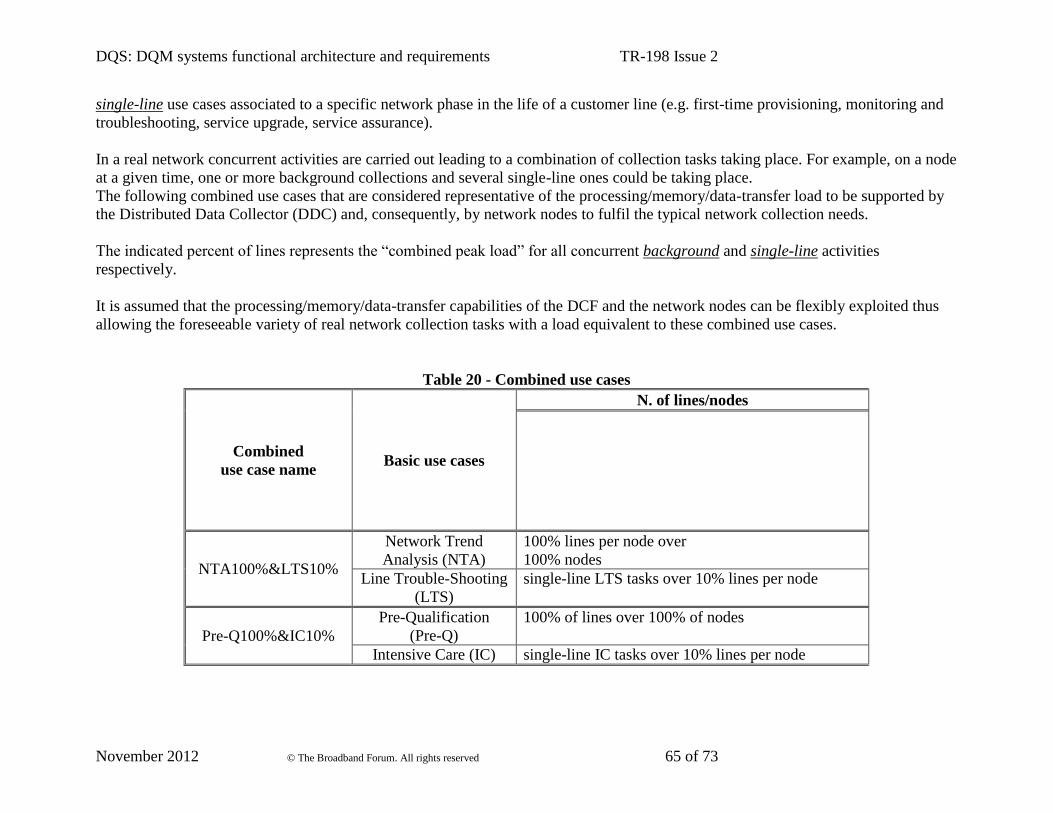
DQS: DQM systems functional architecture and requirements TR-198 Issue 2
November 2012 © The Broadband Forum. All rights reserved 65 of 73
single-line use cases associated to a specific network phase in the life of a customer line (e.g. first-time provisioning, monitoring and
troubleshooting, service upgrade, service assurance).
In a real network concurrent activities are carried out leading to a combination of collection tasks taking place. For example, on a node
at a given time, one or more background collections and several single-line ones could be taking place.
The following combined use cases that are considered representative of the processing/memory/data-transfer load to be supported by
the Distributed Data Collector (DDC) and, consequently, by network nodes to fulfil the typical network collection needs.
The indicated percent of lines represents the “combined peak load” for all concurrent background and single-line activities
respectively.
It is assumed that the processing/memory/data-transfer capabilities of the DCF and the network nodes can be flexibly exploited thus
allowing the foreseeable variety of real network collection tasks with a load equivalent to these combined use cases.
Table 20 - Combined use cases
Combined
use case name Basic use cases
N. of lines/nodes
NTA100%<S10%
Network Trend
Analysis (NTA)
100% lines per node over
100% nodes
Line Trouble-Shooting
(LTS)
single-line LTS tasks over 10% lines per node
Pre-Q100%&IC10%
Pre-Qualification
(Pre-Q)
100% of lines over 100% of nodes
Intensive Care (IC) single-line IC tasks over 10% lines per node

DQS: DQM systems functional architecture and requirements TR-198 Issue 2
November 2012 © The Broadband Forum. All rights reserved 66 of 73
Appendix C. Possible Deployment Scenarios for DCF
DB
Management NetworkDCF
SB i/f
DCF
SB i/f
DCF
SB i/f
DCF
SB i/f
ADF
DCFNE
DQM-ME
NE
DQM-ME
NE
DQM-ME
Figure 6 - Centralised Data Collection from Management Server
The Figure above depicts the scenario where the Data Collection Function is located within the same
physical entity as the ADF. The DCF retrieves data from all the DQM-ME instances in the managed
broadband network via the DCF Southbound Interface defined in Section 6.4.
DB
DCF
NB i/f
DCF
NB i/f
DCF
NB i/fADF
DCF
NB i/f
NE
DQM-ME
DCF
NE
DQM-ME
DCF
NE
DQM-ME
DCF
Management Network
Figure 7 - Distributed Data Collection Function in NE
The figure above depicts the scenario where the Data Collection Function is implemented in an
entity that is physically separate from the ADF function. In this example, the DCF is
implemented in the same physical entity as the DQM-ME.
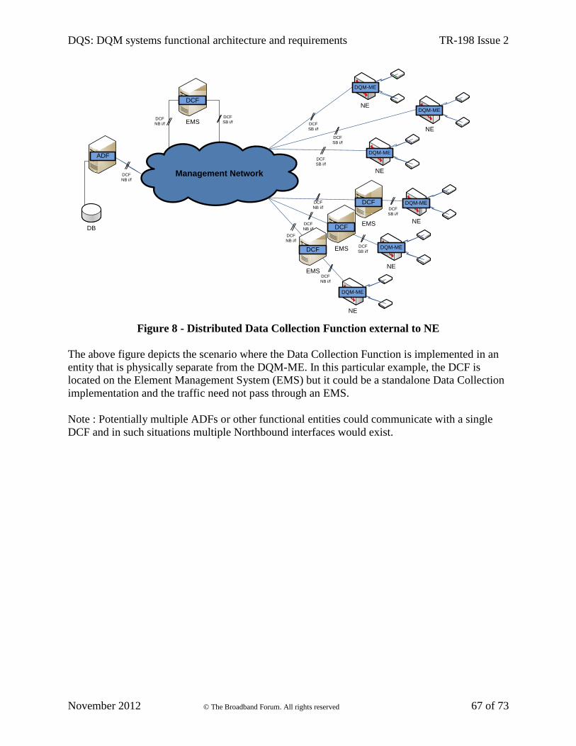
DQS: DQM systems functional architecture and requirements TR-198 Issue 2
November 2012 © The Broadband Forum. All rights reserved 67 of 73
DB
Management NetworkDCF
NB i/f
ADF
EMS
DCF
DCF
NB i/f
DCF
SB i/f
DCF
SB i/f
DCF
SB i/f
NE
DQM-ME
NE
DQM-ME
NE
DQM-ME
NE
DQM-ME
NE
DQM-ME
NE
DQM-ME
DCF
SB i/f
DCF
SB i/f
DCF
SB i/fDCF
NB i/f
EMS
DCFDCF
NB i/f
DCF
NB i/f
DCF
NB i/f
EMS
DCF
EMS
DCF
Figure 8 - Distributed Data Collection Function external to NE
The above figure depicts the scenario where the Data Collection Function is implemented in an
entity that is physically separate from the DQM-ME. In this particular example, the DCF is
located on the Element Management System (EMS) but it could be a standalone Data Collection
implementation and the traffic need not pass through an EMS.
Note : Potentially multiple ADFs or other functional entities could communicate with a single
DCF and in such situations multiple Northbound interfaces would exist.

DQS: DQM systems functional architecture and requirements TR-198 Issue 2
November 2012 © The Broadband Forum. All rights reserved 68 of 73
Appendix D. Possible Deployment Scenarios for PCF
DB
Management Network
NE
NE
NE
PCF
SB i/f
NPSF
PCF
DQM-ME
DQM-ME
DQM-ME
PCF
SB i/f
PCF
SB i/f
PCF
SB i/f
Figure 9 - Profile Configuration Function on same physical entity as NPSF
The above figure depicts the scenario where the Profile Configuration Function is located on the
same physical entity as the NPSF. The PCF sends all the profile configuration data via the PCF
Southbound interface.
DB
Management Network
NPSF
NE
NE
NE
E
NE
DQM-ME
DQM-ME
DQM-ME
DQM-ME
EMS
PCF
PCF
SB i/f
PCF
SB i/f
PCF
SB i/f
PCF
SB i/f
PCF
SB i/f
PCF
NB i/f
PCF
NB i/f
PCF
NB i/f
PCF
NB i/fEMS
PCF
EMS
PCF
Figure 10 - Profile Configuration Function located in the Element Manager

DQS: DQM systems functional architecture and requirements TR-198 Issue 2
November 2012 © The Broadband Forum. All rights reserved 69 of 73
Figure 10 depicts an example in which the PCF is located on the Element Management System
(EMS). Figure 11 below describes a particular example in which the PCF is in the same physical
entity as the DQM-ME.
Figure 11 - Profile Configuration Function located in the Network Element
Potentially multiple NPSFs could communicate with a single PCF and in such situations multiple
Northbound interfaces would exist.

DQS: DQM systems functional architecture and requirements TR-198 Issue 2
November 2012 © The Broadband Forum. All rights reserved 70 of 73
Appendix E. Profile Configuration use cases
This appendix describes basic use cases for Profile Configuration that Service Providers consider
representative of current and foreseeable future needs.
These use cases are not intended to be the only ones mandatorily supported by implementations,
instead they identify for the main Network Operation activities the typical configuration actions
finalising a DQM cycle of monitoring analysis and diagnosis corrective action.
The use cases are listed in a table containing:
Use case name: based on typical Network Operation activities
Objective: the goal of this specific type of configuration task
Resource list: qualitatively indicates if this type of configuration task is typically defined
to a single line or a list of lines (on one or more NEs) and how such list is defined
Profile set: qualitatively indicates if this type of configuration task is typically defined
with a single profile to be applied or a list of profiles subject to a certain selection criteria
Triggers: qualitatively describes the typical triggers which are relevant for this type of
configuration task.
One or more of the indicated triggers may apply though the ways they are typically linked in the
Boolean combination that gives the actual trigger are not described in the table. Notice that the
‘immediate’ trigger is exclusive with regard all the others.
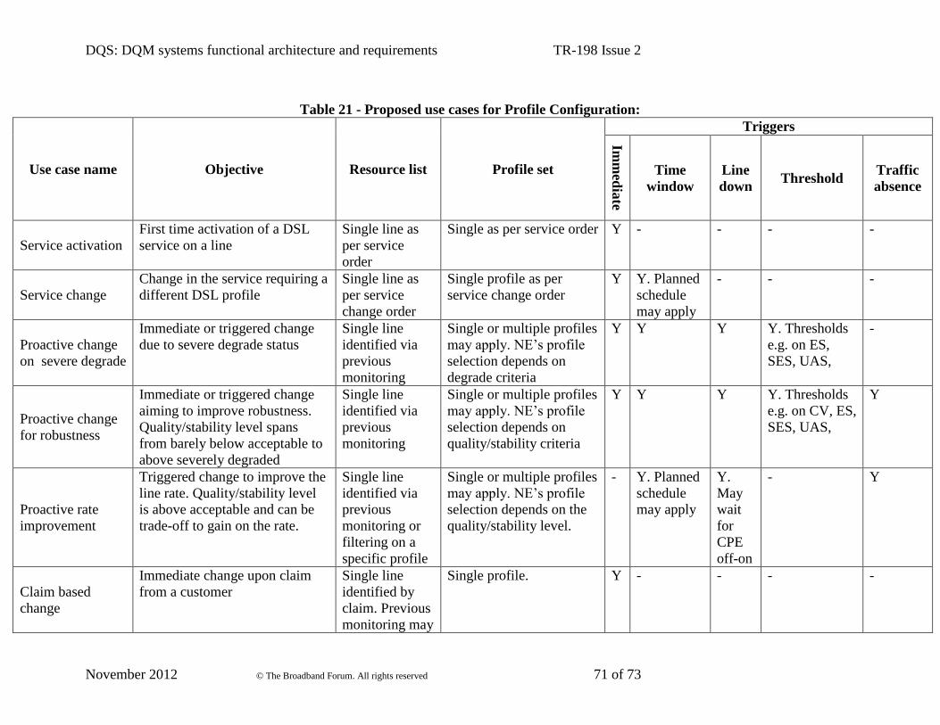
DQS: DQM systems functional architecture and requirements TR-198 Issue 2
November 2012 © The Broadband Forum. All rights reserved 71 of 73
Table 21 - Proposed use cases for Profile Configuration:
Use case name Objective Resource list Profile set
Triggers
Imm
edia
te
Time
window
Line
down Threshold
Traffic
absence
Service activation
First time activation of a DSL
service on a line
Single line as
per service
order
Single as per service order Y - - - -
Service change
Change in the service requiring a
different DSL profile
Single line as
per service
change order
Single profile as per
service change order
Y Y. Planned
schedule
may apply
- - -
Proactive change
on severe degrade
Immediate or triggered change
due to severe degrade status
Single line
identified via
previous
monitoring
Single or multiple profiles
may apply. NE’s profile
selection depends on
degrade criteria
Y Y Y Y. Thresholds
e.g. on ES,
SES, UAS,
-
Proactive change
for robustness
Immediate or triggered change
aiming to improve robustness.
Quality/stability level spans
from barely below acceptable to
above severely degraded
Single line
identified via
previous
monitoring
Single or multiple profiles
may apply. NE’s profile
selection depends on
quality/stability criteria
Y Y Y Y. Thresholds
e.g. on CV, ES,
SES, UAS,
Y
Proactive rate
improvement
Triggered change to improve the
line rate. Quality/stability level
is above acceptable and can be
trade-off to gain on the rate.
Single line
identified via
previous
monitoring or
filtering on a
specific profile
Single or multiple profiles
may apply. NE’s profile
selection depends on the
quality/stability level.
- Y. Planned
schedule
may apply
Y.
May
wait
for
CPE
off-on
- Y
Claim based
change
Immediate change upon claim
from a customer
Single line
identified by
claim. Previous
monitoring may
Single profile. Y - - - -

DQS: DQM systems functional architecture and requirements TR-198 Issue 2
November 2012 © The Broadband Forum. All rights reserved 72 of 73
Use case name Objective Resource list Profile set
Triggers
Imm
edia
te
Time
window
Line
down Threshold
Traffic
absence
have happened.
Network proactive
assurance on THR
crossing
Triggered change over a set of
lines identified as critical or part
of a category subject to special
care.
Multiple lines
identified via
previous
monitoring or
filtering on a
specific profile.
Single profile.
Also multiple profiles
may apply.
- Y Y Y Y
Service migration
Planned change over a set of
lines with the same service.
Multiple lines
identified via
filtering on a
specific profile.
Single profile. Y Y Y - Y
Profile clean-up
Planned change so that a specific
profile is not configured on any
line in (a part of) the network.
The aim is then to get rid of that
profile from NEs, EMS and all
other involved network systems.
Multiple lines
identified via
filtering on a
specific profile.
Single profile. Y Y Y Y

DQS: DQM systems functional architecture and requirements TR-198 Issue 2
November 2012 © The Broadband Forum. All rights reserved 73 of 73
End of Broadband Forum Technical Report TR-198