Embed Size (px)
DESCRIPTION
Â
Citation preview
Technical Data 50 Hz / 60Hz DIN/IECVertical centrifugal immersible pumps
series: DPV(C/S) 2 - 4 - 6 - 10 - 15Design Version B

2
3
Table of Contents
1 Pump introduction1.1 General .................................................................................................................................................. 51.2 Model key............................................................................................................................................... 51.3 Operation ............................................................................................................................................... 51.4 Measuring, draining and venting............................................................................................................ 51.5 Working range........................................................................................................................................ 61.6 Basic material variants........................................................................................................................... 61.7 Pump bearing......................................................................................................................................... 71.8 Modular selection................................................................................................................................... 71.9 Approval................................................................................................................................................. 7
2 Performance characteristics2.1 Performance range 50Hz....................................................................................................................... 82.2 Performance range 60Hz....................................................................................................................... 82.3 Performance curve details ..................................................................................................................... 92.4 Minimum efficiency index....................................................................................................................... 92.5 Performance with variable frequency drive............................................................................................ 92.6 How to read the values from the curves .............................................................................................. 10
3 Curves and dimensions3.1 Hydraulic performance curve DPVCI 2 B - 50Hz -2 pole ..................................................................... 123.2 DPV(C/S) 2 B - 50Hz - 2 pole - DIN..................................................................................................... 133.3 Hydraulic performance curve DPVCI 4 B - 50Hz - 2 pole .................................................................... 143.4 DPVCI 4 B - 50Hz - 2 pole - DIN.......................................................................................................... 153.5 Hydraulic performance curve DPVCI 6 B - 50Hz - 2 pole .................................................................... 163.6 DPVCI 6 B - 50Hz - 2 pole - DIN.......................................................................................................... 173.7 Hydraulic performance curve DPVCI 10 B - 50Hz - 2 pole .................................................................. 183.8 DPVCI 10 B - 50Hz - 2 pole - DIN........................................................................................................ 193.9 Hydraulic performance curve DPVCI 15 B - 50Hz - 2 pole .................................................................. 203.10 DPVCI 15 B - 50Hz - 2 pole - DIN........................................................................................................ 213.11 Hydraulic performance curve DPVCI 2 B - 60Hz -2 pole ..................................................................... 223.12 DPV(C/S) 2 B - 60Hz - 2 pole - DIN..................................................................................................... 233.13 Hydraulic performance curve DPVCI 4 B - 60Hz - 2 pole .................................................................... 243.14 DPVCI 4 B - 60Hz - 2 pole - DIN.......................................................................................................... 253.15 Hydraulic performance curve DPVCI 6 B - 60Hz - 2 pole .................................................................... 263.16 DPVCI 6 B - 60Hz - 2 pole - DIN.......................................................................................................... 273.17 Hydraulic performance curve DPVCI 10 B - 60Hz - 2 pole .................................................................. 283.18 DPVCI 10 B - 60Hz - 2 pole - DIN........................................................................................................ 293.19 Hydraulic performance curve DPVCI 15 B - 60Hz - 2 pole .................................................................. 303.20 DPVCI 15 B - 60Hz - 2 pole - DIN........................................................................................................ 31
4 Seals4.1 Mechanical seal option specifications.................................................................................................. 32
5 Motors and motor options5.1 General ................................................................................................................................................ 335.2 Options................................................................................................................................................. 335.3 Standard motor data 2P 50Hz.............................................................................................................. 335.4 Standard motor data 2P 60Hz.............................................................................................................. 34
6 Frequency drive6.1 General ................................................................................................................................................ 35
4
6.2 Working range...................................................................................................................................... 356.3 General specifications.......................................................................................................................... 356.4 Detailed specifications ......................................................................................................................... 35
7 Materials7.1 Parts overview ..................................................................................................................................... 36
8 Medium handled8.1 Medium handled .................................................................................................................................. 38
5
1 Pump introduction
1.1 General
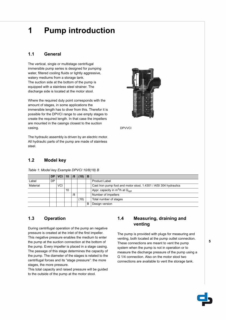
The vertical, single or multistage centrifugal immersible pump series is designed for pumping water, filtered cooling fluids or lightly aggressive, watery mediums from a storage tank.The suction side at the bottom of the pump is equipped with a stainless steel strainer. The discharge side is located at the motor stool.
Where the required duty point corresponds with the amount of stages, in some applications the immersible length has to diver from this. Therefor it is possible for the DPVCI range to use empty stages to create the required length. In that case the impellers are mounted in the casings closest to the suction casing.
The hydraulic assembly is driven by an electric motor. All hydraulic parts of the pump are made of stainless steel.
1.2 Model key
Table 1: Model key Example DPVCI 10/8(18) B
1.3 Operation
During centrifugal operation of the pump an negative pressure is created at the inlet of the first impeller. This negative pressure enables the medium to enter the pump at the suction connection at the bottom of the pump. Every impeller is placed in a stage casing.The passage of this stage determines the capacity of the pump. The diameter of the stages is related to the centrifugal forces and its “stage pressure”: the more stages, the more pressure.This total capacity and raised pressure will be guided to the outside of the pump at the motor stool.
1.4 Measuring, draining and venting
The pump is provided with plugs for measuring and venting, both located at the pump outlet connection.These connections are meant to vent the pump system when the pump is not in operation or to measure the discharge pressure of the pump using a G 1/4 connection. Also on the motor stool two connections are available to vent the storage tank.
DPVVCI
DP VCI 10 /8 (18) B
Label DP Product Label
Material VCI Cast Iron pump foot and motor stool, 1.4301 / AISI 304 hydraulics
10 Appr. capacity in m3/h at Qopt
/8 Number of impellers
(18) Total number of stages
B Design version
6
1.5 Working range
The working range is depending on the application and the combination of pressure and temperature. For specific and detailed limits please consult the working ranges as described in the paragraph 1.8. The overall working range of the pumps can be summarised as follows:Table 2: Specification of the working range
1.5.1 Minimum capacity
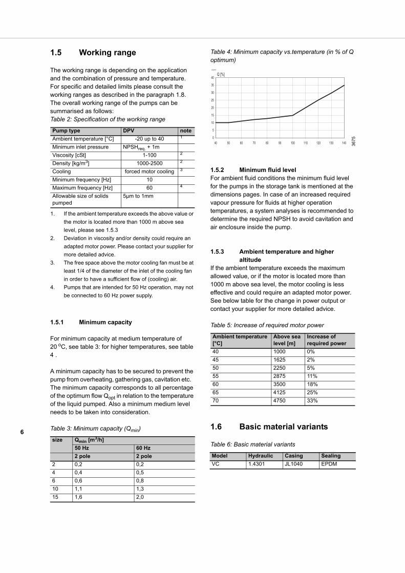
For minimum capacity at medium temperature of 20 oC, see table 3: for higher temperatures, see table 4 .
A minimum capacity has to be secured to prevent the pump from overheating, gathering gas, cavitation etc. The minimum capacity corresponds to all percentage of the optimum flow Qopt in relation to the temperature of the liquid pumped. Also a minimum medium level needs to be taken into consideration.
Table 3: Minimum capacity (Qmin)
Table 4: Minimum capacity vs.temperature (in % of Q optimum)
1.5.2 Minimum fluid levelFor ambient fluid conditions the minimum fluid level for the pumps in the storage tank is mentioned at the dimensions pages. In case of an increased required vapour pressure for fluids at higher operation temperatures, a system analyses is recommended to determine the required NPSH to avoid cavitation and air enclosure inside the pump.
1.5.3 Ambient temperature and higher altitude
If the ambient temperature exceeds the maximum allowed value, or if the motor is located more than 1000 m above sea level, the motor cooling is less effective and could require an adapted motor power. See below table for the change in power output or contact your supplier for more detailed advice.
Table 5: Increase of required motor power
1.6 Basic material variants
Table 6: Basic material variants
Pump type DPV note
Ambient temperature [°C] -20 up to 40 1
1. If the ambient temperature exceeds the above value or
the motor is located more than 1000 m above sea
level, please see 1.5.3
Minimum inlet pressure NPSHreq. + 1m
Viscosity [cSt] 1-100 2
2. Deviation in viscosity and/or density could require an
adapted motor power. Please contact your supplier for
more detailed advice.
Density [kg/m3] 1000-2500 2
Cooling forced motor cooling 3
3. The free space above the motor cooling fan must be at
least 1/4 of the diameter of the inlet of the cooling fan
in order to have a sufficient flow of (cooling) air.
Minimum frequency [Hz] 10
Maximum frequency [Hz] 60 4
4. Pumps that are intended for 50 Hz operation, may not
be connected to 60 Hz power supply.
Allowable size of solids pumped
5µm to 1mm
size Qmin [m3/h]
50 Hz 60 Hz
2 pole 2 pole
2 0,2 0,2
4 0,4 0,5
6 0,6 0,8
10 1,1 1,3
15 1,6 2,0
ID3675
367
5
Ambient temperature [°C]
Above sea level [m]
Increase of required power
40 1000 0%
45 1625 2%
50 2250 5%
55 2875 11%
60 3500 18%
65 4125 25%
70 4750 33%
Model Hydraulic Casing Sealing
VC 1.4301 JL1040 EPDM
0
5
10
15
20
25
30
35
40
40 50 60 70 80 90 100 110 120 130 140
Q [%]
o
7
1.7 Pump bearing
Medium lubricated stage bearingTungsten Carbide against Ceramic
1.8 Modular selection
To suit almost every application the pump is assembled out of modules which can be selected depending on the required working range.
Basic modules are:
• Basic pump model, which defines the capacity, pressure and basic material. Temperature range -20 up to 120 oC
• Total stages, which defines the length of the pump suitable for the storage tank.
• Sealing, which define the elastomers and the mechanical seal. A cartridge seal construction is equipped as default. Temperature and pressure range, see chapter 4.1
• Electric motor, which defines all requirements of the motor such as motor size, power, voltage, frequency and all possible motor accessories.
For assembling the total amount of stages to the motor stool an additional upper stage casing is required. Therefor when all visible stage stages are counted from the hydraulics, the sum will be the total amount of stages added by 1.
1.9 Approval
CE Conformity with European Safety Directive
8
2 Performance characteristics
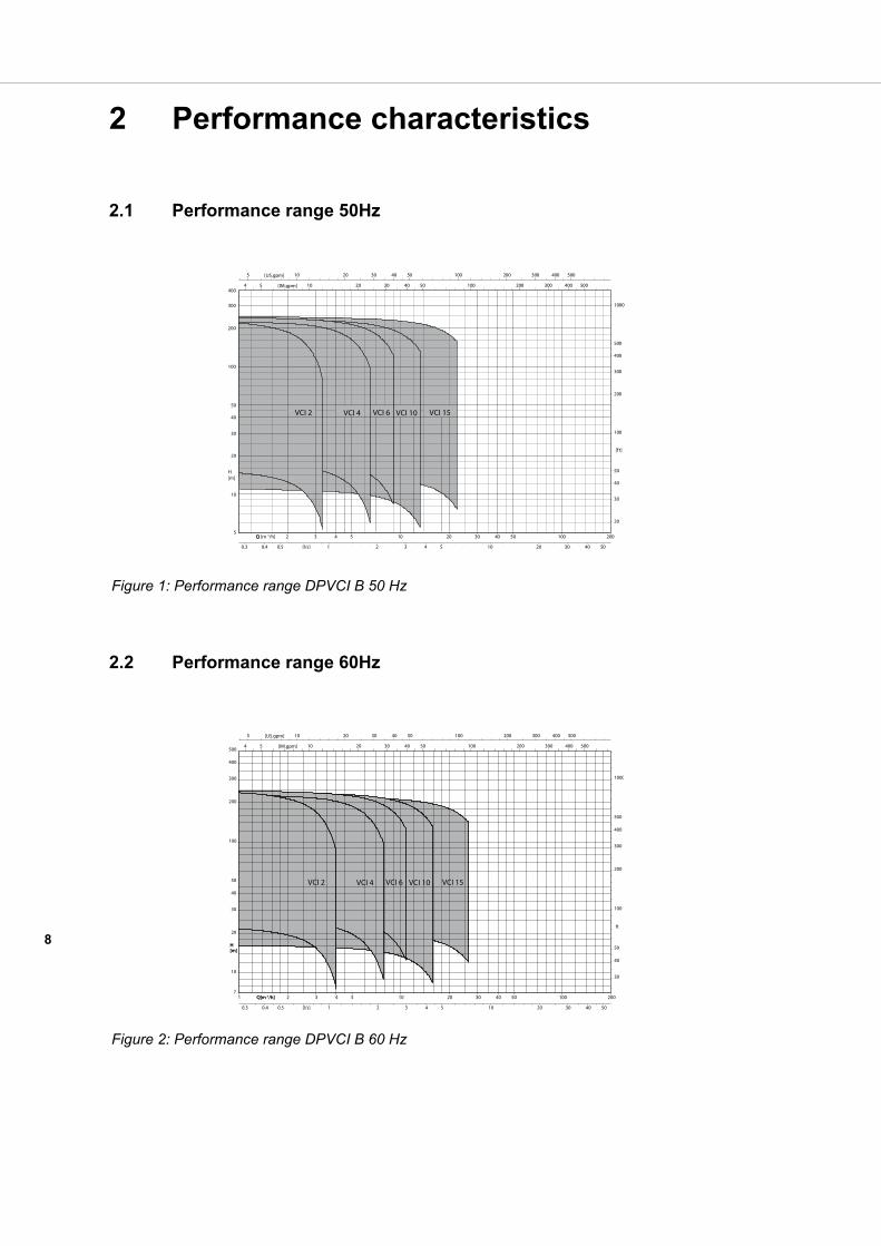
2.1 Performance range 50Hz
2.2 Performance range 60Hz
Figure 1: Performance range DPVCI B 50 Hz
Figure 2: Performance range DPVCI B 60 Hz
9
2.3 Performance curve details
The performance diagrams give a global overview of all the pump models the shaded models are mentioned in this documentation. Detailed characteristics are given for each model showing the hydraulic efficiency, NPSHreq, and shaft power as well.
The performance of the pump depends on the number of stages. As per example:
The detailed performance curves are in accordance with ISO 9906:2012 (Grade 3B).
The pumps van be configured with multiple types of motors. Therefore the performance data, like Q/H, efficiency and shaft power used for published curves are converted to the average speed per motor power. To refine this data the published data has to be corrected accordingly.
The published curves and data mentioned on the pump are based on the following rotational speed:
Table 7: Rated motor power and speed
The characteristics given are based on:• De-aerated water at a temperature of 20 °C• Density of 1,0 kg/dm3
• Kinematical viscosity of 1 mm2/s (1 cst)
2.4 Minimum efficiency index
Per January 1st 2013 for multistage pumps (reference 50Hz and 2 poles) a new Commission Regulation (EU) No 547/2012 as part of the Directive 2009/125/EC is mandatory.According to this the pumps need to apply to a new Minimum Efficiency Index (MEI). This value is set to be >= 0.10
For the design version B immersible pump range the following values are applicable:
Table 8: Minimum efficiency index
2.5 Performance with variable frequency drive
The minimum frequency of the DP motor should be limited to 10 Hz to ensure sufficient cooling. When the rotational speed exceeds the nominal speed of the motor, make sure that the power output of the motor is suitable to drive the corresponding pump model.
The performance of the pump differs from the fixed speed performance according to the recalculation scheme.
DPVCI 4/20(18) B: series 4 20 stages with 18 full head impellers
Rated motor power
Rated speed at 50 Hz [rpm] 2P
Rated speed at 60 Hz [rpm] 2P
0,37 and 0,55 kW 2800 3460
to 2,2 kW 2880 3460
to 4 kW 2920 3510
to 7,5 kW 2940 3530
to 22 kW 2950 3550
to 45 kW 2960 3550
Pump range
Minimum Efficiency index
DPV 2 MEI ≥ 0.70
DPV 4 MEI ≥ 0.70
DPV 6 MEI ≥ 0.70
DPV 10 MEI ≥ 0.70
DPV 15 MEI ≥ 0.40
10
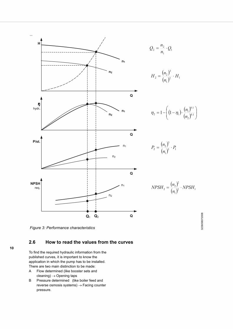
2.6 How to read the values from the curves
To find the required hydraulic information from the published curves, it is important to know the application in which the pump has to be installed.There are two main distinction to be made:A Flow determined (like booster sets and
cleaning) Opening tapsB Pressure determined (like boiler feed and
reverse osmosis systems) Facing counter pressure.
ID3238
Figure 3: Performance characteristics 323
8/08
0720
08
11
22 Q
nnQ
131
32
2 PnnP
121
22
2 NPSHnnNPSH
Q2Q1
1.02
1.01
12 11nn
121
22
2 HnnH
Q
Q
Q
Q
NPSHreq.
P/st.
hydr.
H
n1
n2
n1n2
n2
n1
n1
n2
11
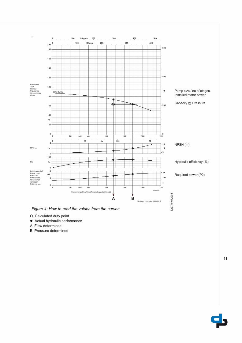
O Calculated duty point Actual hydraulic performanceA Flow determinedB Pressure determined
3227
Figure 4: How to read the values from the curves 3227
/040
7200
8
Pump size / no of stages.Installed motor power
Capacity @ Pressure
NPSH (m)
Hydraulic efficiency (%)
Required power (P2)
12
3 Curves and dimensions
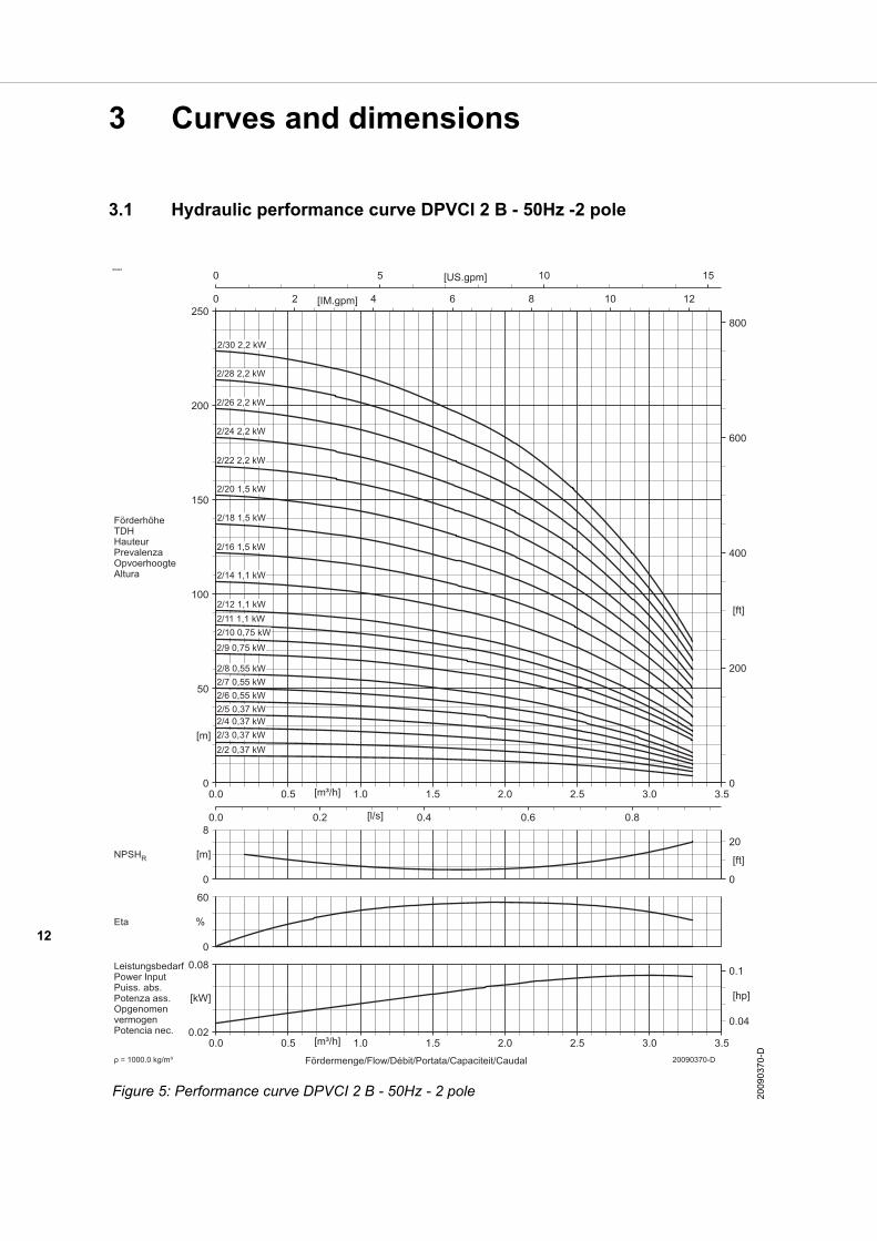
3.1 Hydraulic performance curve DPVCI 2 B - 50Hz -2 pole
ID3424
Figure 5: Performance curve DPVCI 2 B - 50Hz - 2 pole 2009
037
0-D

13
3.2 DPV(C/S) 2 B - 50Hz - 2 pole - DIN
To determine the correct length of the pump see both following explanation and table.
The length F3 corresponds with the length of the applied motor power. F4 corresponds with the total number of stages. Example: 2/16(30) F3=396mm, F4=732mm. Table 9: General dimensions
length incl. motor length excl. motor
Full stage pump F1 F2
Pump with empty stages F3 + F4 F3 + F4 -LB
ID3436
*including packing
Model Seal pressure
Power Motor dimensions DPVCI
Full stage [kW] E1 [mm]
E2 [mm]
LB [mm]
F1 [mm]
F2 [mm]
F3 [mm]
F4 [mm]
Mass* [kg]
2/2(2) PN10 0,37 134 107 219 445 226 315 130 14
2/3(3) 0,37 134 107 219 466 247 315 151 14
2/4(4) 0,37 134 107 219 488 269 315 173 14
2/5(5) 0,37 134 107 219 509 290 315 194 15
2/6(6) 0,55 134 107 243 555 312 339 216 17
2/7(7) 0,55 134 107 243 576 333 339 237 17
2/8(8) 0,55 134 107 243 598 355 339 259 18
2/9(9) 0,75 150 115 234 620 386 340 280 20
2/10(10) 0,75 150 115 234 642 408 340 302 20
2/11(11) 1,1 150 115 264 693 429 370 323 23
2/12(12) 1,1 150 115 264 715 451 370 345 23
2/14(14) PN25 1,1 150 115 264 758 494 370 388 24
2/16(16) 1,5 176 141 280 827 547 396 431 29
2/18(18) 1,5 176 141 280 870 590 396 474 29
2/20(20) 1,5 176 141 280 913 633 396 517 30
2/22(22) 2,2 176 141 280 956 676 396 560 35
2/24(24) 2,2 176 141 280 999 719 396 603 36
2/26(26) 2,2 176 141 280 1042 762 396 646 36
2/28(28) 2,2 176 141 280 1085 805 396 689 37
2/30(30) 2,2 176 141 280 1128 848 396 732 38
14
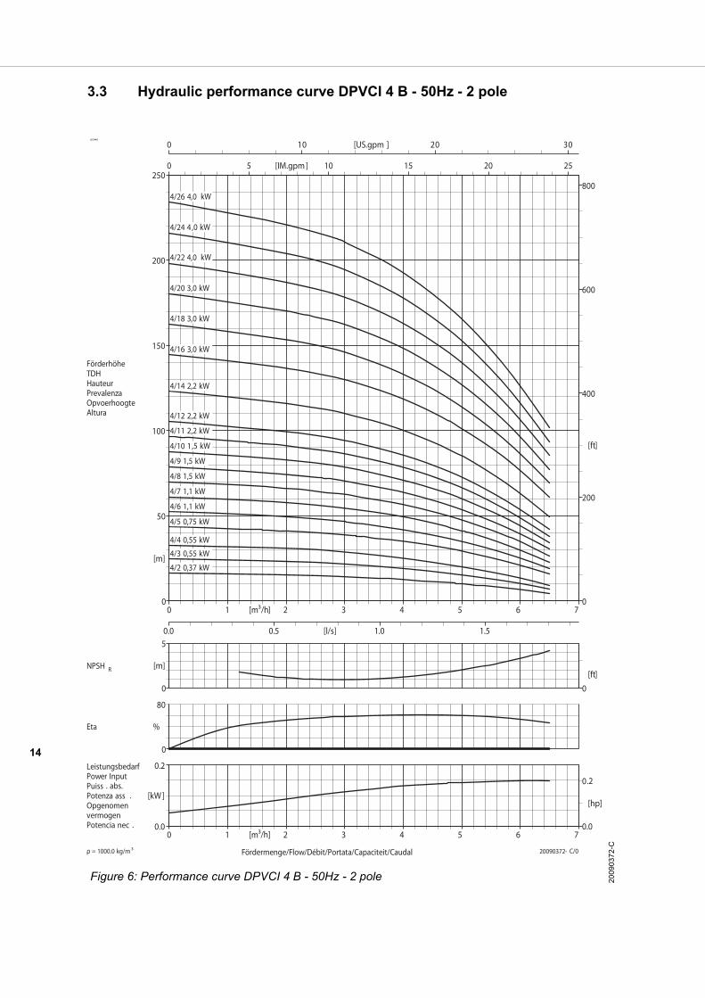
3.3 Hydraulic performance curve DPVCI 4 B - 50Hz - 2 pole
ID3448
Figure 6: Performance curve DPVCI 4 B - 50Hz - 2 pole 2009
0372
-C
15
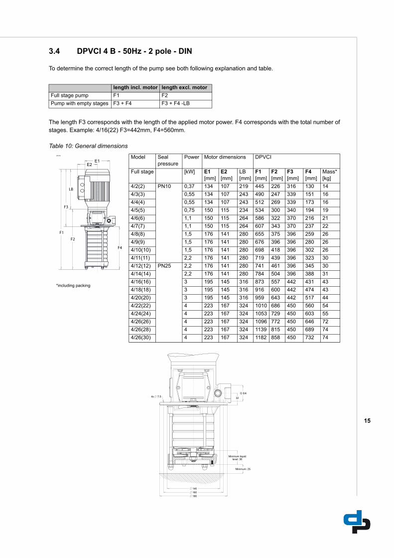
3.4 DPVCI 4 B - 50Hz - 2 pole - DIN
To determine the correct length of the pump see both following explanation and table.
The length F3 corresponds with the length of the applied motor power. F4 corresponds with the total number of stages. Example: 4/16(22) F3=442mm, F4=560mm. Table 10: General dimensions
length incl. motor length excl. motor
Full stage pump F1 F2
Pump with empty stages F3 + F4 F3 + F4 -LB
ID3436
*including packing
Model Seal pressure
Power Motor dimensions DPVCI
Full stage [kW] E1 [mm]
E2 [mm]
LB [mm]
F1 [mm]
F2 [mm]
F3 [mm]
F4 [mm]
Mass* [kg]
4/2(2) PN10 0,37 134 107 219 445 226 316 130 14
4/3(3) 0,55 134 107 243 490 247 339 151 16
4/4(4) 0,55 134 107 243 512 269 339 173 16
4/5(5) 0,75 150 115 234 534 300 340 194 19
4/6(6) 1,1 150 115 264 586 322 370 216 21
4/7(7) 1,1 150 115 264 607 343 370 237 22
4/8(8) 1,5 176 141 280 655 375 396 259 26
4/9(9) 1,5 176 141 280 676 396 396 280 26
4/10(10) 1,5 176 141 280 698 418 396 302 26
4/11(11) 2,2 176 141 280 719 439 396 323 30
4/12(12) PN25 2,2 176 141 280 741 461 396 345 30
4/14(14) 2,2 176 141 280 784 504 396 388 31
4/16(16) 3 195 145 316 873 557 442 431 43
4/18(18) 3 195 145 316 916 600 442 474 43
4/20(20) 3 195 145 316 959 643 442 517 44
4/22(22) 4 223 167 324 1010 686 450 560 54
4/24(24) 4 223 167 324 1053 729 450 603 55
4/26(26) 4 223 167 324 1096 772 450 646 72
4/26(28) 4 223 167 324 1139 815 450 689 74
4/26(30) 4 223 167 324 1182 858 450 732 74
16
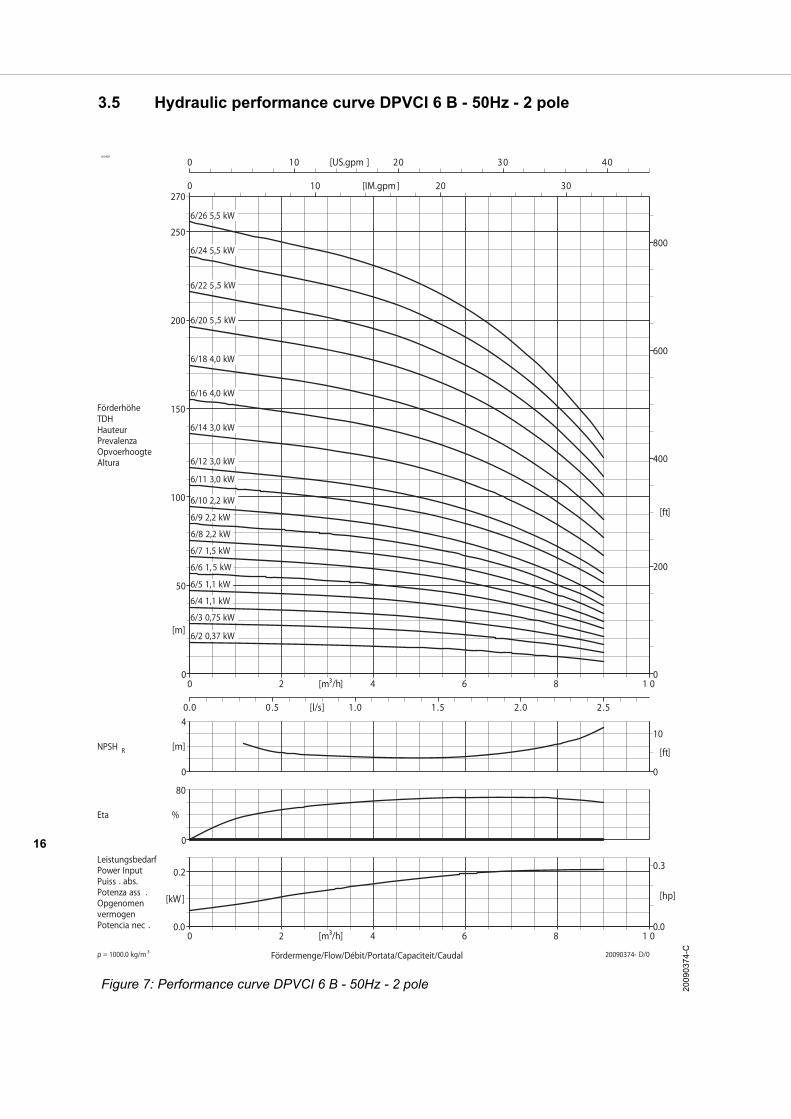
3.5 Hydraulic performance curve DPVCI 6 B - 50Hz - 2 pole
ID3425
Figure 7: Performance curve DPVCI 6 B - 50Hz - 2 pole 2009
0374
-C
17
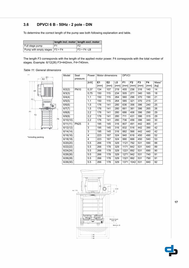
3.6 DPVCI 6 B - 50Hz - 2 pole - DIN
To determine the correct length of the pump see both following explanation and table.
The length F3 corresponds with the length of the applied motor power. F4 corresponds with the total number of stages. Example: 6/12(26) F3=442mm, F4=740mm. Table 11: General dimensions
length incl. motor length excl. motor
Full stage pump F1 F2
Pump with empty stages F3 + F4 F3 + F4 -LB
ID3436
*including packing
Model Seal pressure
Power Motor dimensions DPVCI
[kW] E1 [mm]
E2 [mm]
LB [mm]
F1 [mm]
F2 [mm]
F3 [mm]
F4 [mm]
Mass* [kg]
6/2(2) PN10 0,37 134 107 219 455 236 316 140 14
6/3(3) 0,75 150 115 234 505 271 340 165 18
6/4(4) 1,1 150 115 264 560 296 370 190 21
6/5(5) 1,1 150 115 264 585 321 370 215 21
6/6(6) 1,5 176 141 280 636 356 396 240 25
6/7(7) 1,5 176 141 280 661 381 396 265 26
6/8(8) 2,2 176 141 280 686 406 396 290 29
6/9(9) 2,2 176 141 280 711 431 396 315 29
6/10(10) 2,2 176 141 280 736 456 396 340 30
6/11(11) PN25 3 195 145 316 807 491 442 365 41
6/12(12) 3 195 145 316 832 516 442 390 42
6/14(14) 3 195 145 316 882 566 442 440 42
6/16(16) 4 223 167 324 940 616 450 490 52
6/18(18) 4 223 167 324 990 666 450 540 53
6/20(20) 5.5 266 178 329 1121 792 531 590 88
6/22(22) 5.5 266 178 329 1171 842 531 640 89
6/24(24) 5.5 266 178 329 1221 892 531 690 90
6/26(26) 5.5 266 178 329 1271 942 531 740 91
6/26(28) 5.5 266 178 329 1321 992 531 790 91
6/26(30) 5.5 266 178 329 1371 1042 531 840 92
18
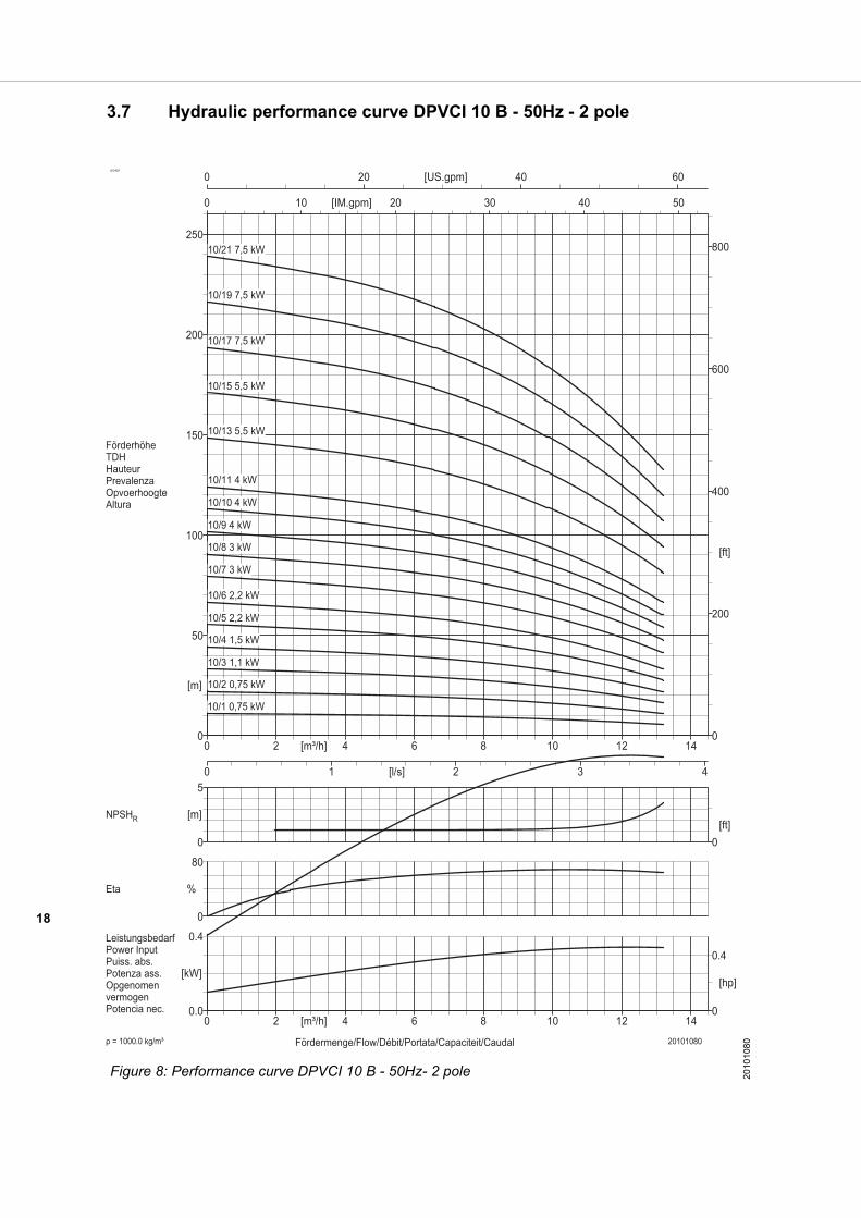
3.7 Hydraulic performance curve DPVCI 10 B - 50Hz - 2 pole
ID3425
Figure 8: Performance curve DPVCI 10 B - 50Hz- 2 pole 2010
1080

19
3.8 DPVCI 10 B - 50Hz - 2 pole - DIN
To determine the correct length of the pump see both following explanation and table.
The length F3 corresponds with the length of the applied motor power. F4 corresponds with the total number of stages. Example: 10/8(13) F3=455mm, F4=445mm. Table 12: General dimensions
length incl. motor length excl. motor
Full stage pump F1 F2
Pump with empty stages F3 + F4 F3 + F4 -LB
ID3436
*including packing
Model Seal pressure
Power Motor dimensions DPVCI
Full stage [kW] E1 [mm]
E2 [mm]
LB [mm]
F1 [mm]
F2 [mm]
F3 [mm]
F4 [mm]
Mass* [kg]
10/1(2) PN10 0,75 150 115 234 497 263 343 154 17
10/2(2) 0,75 150 115 234 497 263 343 154 17
10/3(3) 1,1 150 115 264 554 290 373 181 20
10/4(4) 1,5 176 141 280 606 326 399 207 32
10/5(5) 2,2 176 141 280 633 353 399 236 36
10/6(6) 2,2 176 141 280 686 406 399 287 37
10/7(7) 3 195 145 316 732 416 455 313 47
10/8(8) 3 195 145 316 758 442 445 313 48
10/9(9) PN25 4 223 167 324 792 468 453 339 58
10/10(10) 4 223 167 324 819 495 453 366 58
10/11(11) 4 223 167 324 845 521 453 392 59
10/13(13) 5,5 266 178 329 984 655 539 445 93
10/15(15) 5,5 266 178 329 1037 708 539 498 94
10/17(17) 7,5 266 178 377 1138 761 587 551 127
10/19(19) 7,5 266 178 377 1191 814 587 604 129
10/21(21) 7,5 266 178 377 1244 867 587 657 130
20
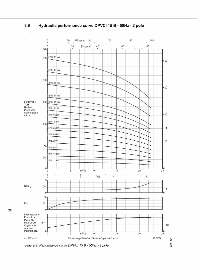
3.9 Hydraulic performance curve DPVCI 15 B - 50Hz - 2 pole
ID3425
Figure 9: Performance curve DPVCI 15 B - 50Hz - 2 pole 2010
1084
21
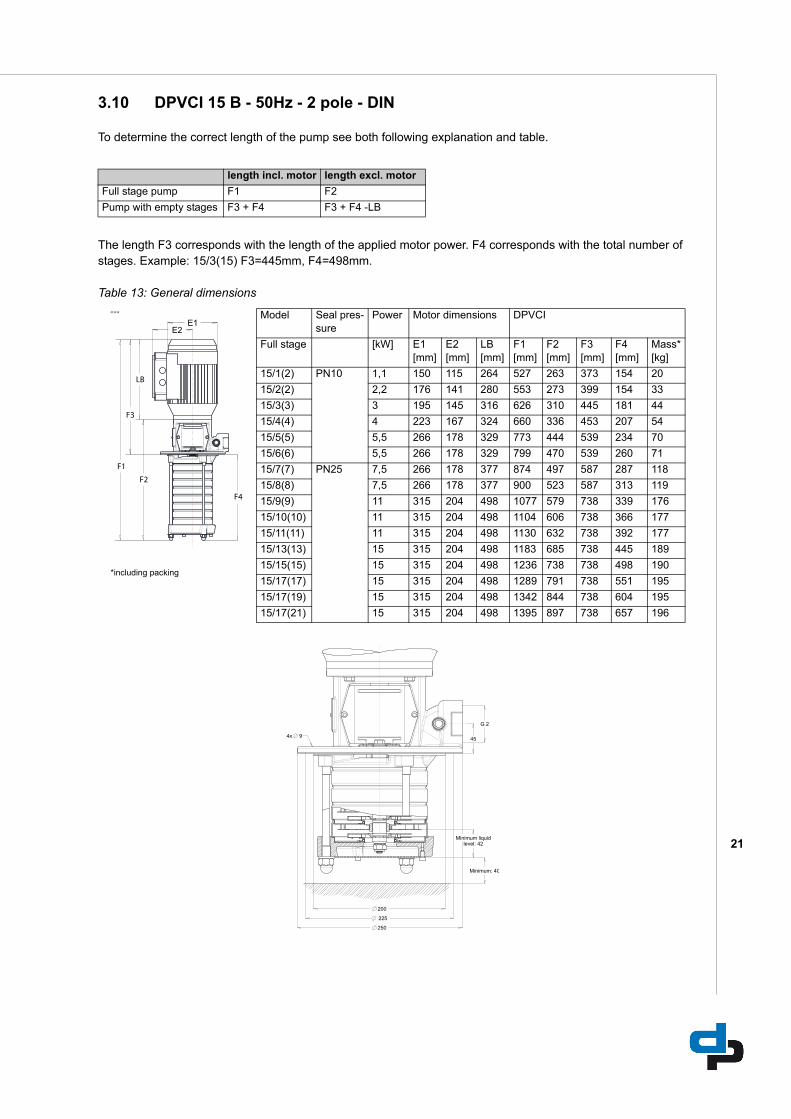
3.10 DPVCI 15 B - 50Hz - 2 pole - DIN
To determine the correct length of the pump see both following explanation and table.
The length F3 corresponds with the length of the applied motor power. F4 corresponds with the total number of stages. Example: 15/3(15) F3=445mm, F4=498mm. Table 13: General dimensions
length incl. motor length excl. motor
Full stage pump F1 F2
Pump with empty stages F3 + F4 F3 + F4 -LB
ID3436
*including packing
Model Seal pres-sure
Power Motor dimensions DPVCI
Full stage [kW] E1 [mm]
E2 [mm]
LB [mm]
F1 [mm]
F2 [mm]
F3 [mm]
F4 [mm]
Mass* [kg]
15/1(2) PN10 1,1 150 115 264 527 263 373 154 20
15/2(2) 2,2 176 141 280 553 273 399 154 33
15/3(3) 3 195 145 316 626 310 445 181 44
15/4(4) 4 223 167 324 660 336 453 207 54
15/5(5) 5,5 266 178 329 773 444 539 234 70
15/6(6) 5,5 266 178 329 799 470 539 260 71
15/7(7) PN25 7,5 266 178 377 874 497 587 287 118
15/8(8) 7,5 266 178 377 900 523 587 313 119
15/9(9) 11 315 204 498 1077 579 738 339 176
15/10(10) 11 315 204 498 1104 606 738 366 177
15/11(11) 11 315 204 498 1130 632 738 392 177
15/13(13) 15 315 204 498 1183 685 738 445 189
15/15(15) 15 315 204 498 1236 738 738 498 190
15/17(17) 15 315 204 498 1289 791 738 551 195
15/17(19) 15 315 204 498 1342 844 738 604 195
15/17(21) 15 315 204 498 1395 897 738 657 196
22
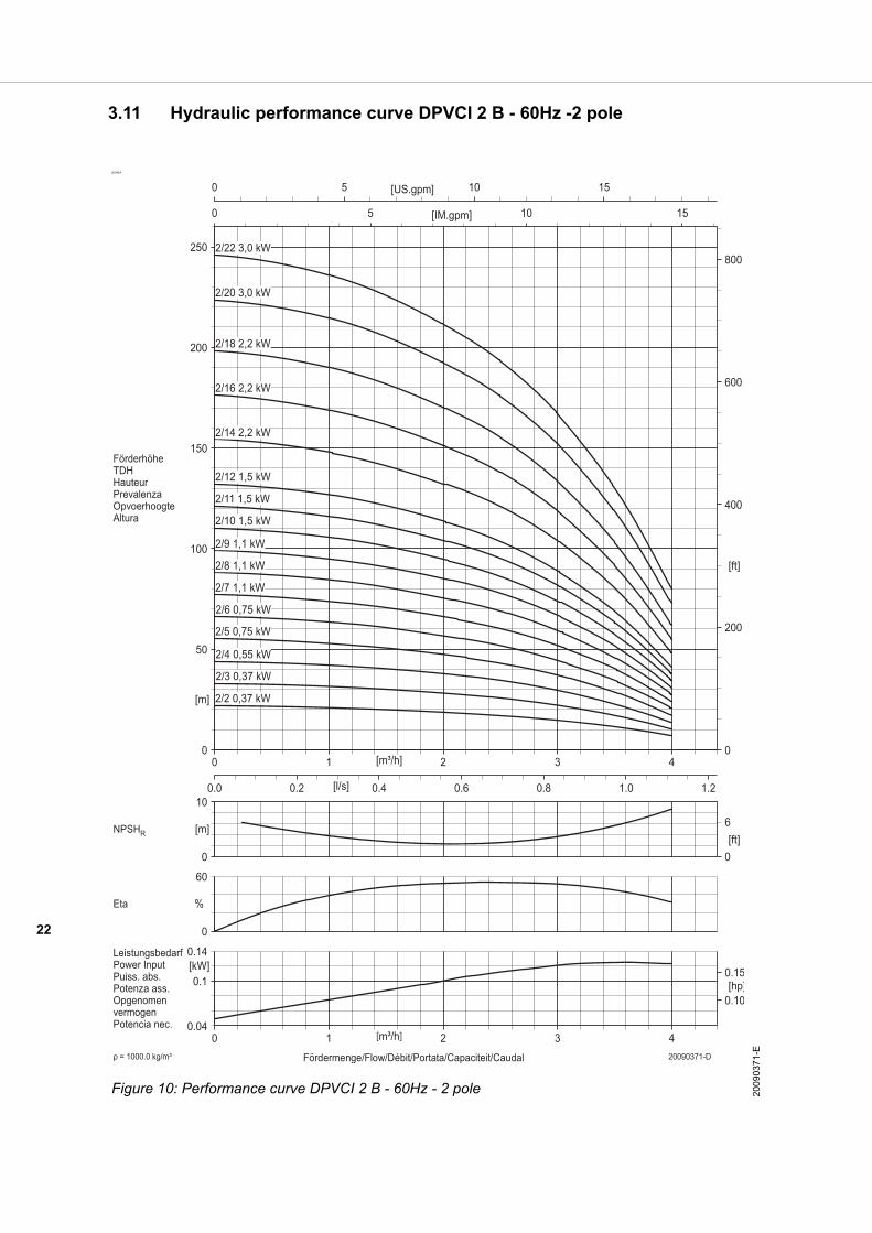
3.11 Hydraulic performance curve DPVCI 2 B - 60Hz -2 pole
ID3424
Figure 10: Performance curve DPVCI 2 B - 60Hz - 2 pole 200
9037
1-E
23
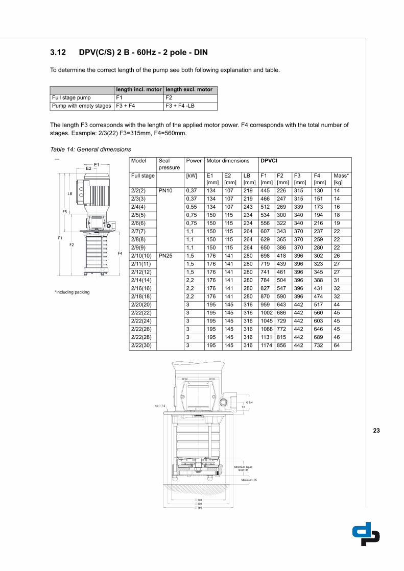
3.12 DPV(C/S) 2 B - 60Hz - 2 pole - DIN
To determine the correct length of the pump see both following explanation and table.
The length F3 corresponds with the length of the applied motor power. F4 corresponds with the total number of stages. Example: 2/3(22) F3=315mm, F4=560mm. Table 14: General dimensions
length incl. motor length excl. motor
Full stage pump F1 F2
Pump with empty stages F3 + F4 F3 + F4 -LB
ID3436
*including packing
Model Seal pressure
Power Motor dimensions DPVCI
Full stage [kW] E1 [mm]
E2 [mm]
LB [mm]
F1 [mm]
F2 [mm]
F3 [mm]
F4 [mm]
Mass* [kg]
2/2(2) PN10 0,37 134 107 219 445 226 315 130 14
2/3(3) 0,37 134 107 219 466 247 315 151 14
2/4(4) 0,55 134 107 243 512 269 339 173 16
2/5(5) 0,75 150 115 234 534 300 340 194 18
2/6(6) 0,75 150 115 234 556 322 340 216 19
2/7(7) 1,1 150 115 264 607 343 370 237 22
2/8(8) 1,1 150 115 264 629 365 370 259 22
2/9(9) 1,1 150 115 264 650 386 370 280 22
2/10(10) PN25 1,5 176 141 280 698 418 396 302 26
2/11(11) 1,5 176 141 280 719 439 396 323 27
2/12(12) 1,5 176 141 280 741 461 396 345 27
2/14(14) 2,2 176 141 280 784 504 396 388 31
2/16(16) 2,2 176 141 280 827 547 396 431 32
2/18(18) 2,2 176 141 280 870 590 396 474 32
2/20(20) 3 195 145 316 959 643 442 517 44
2/22(22) 3 195 145 316 1002 686 442 560 45
2/22(24) 3 195 145 316 1045 729 442 603 45
2/22(26) 3 195 145 316 1088 772 442 646 45
2/22(28) 3 195 145 316 1131 815 442 689 46
2/22(30) 3 195 145 316 1174 856 442 732 64
24
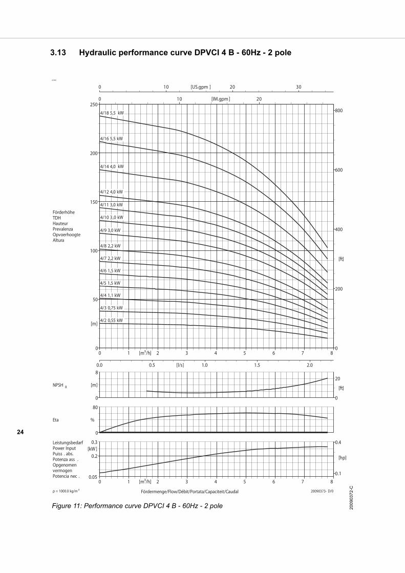
3.13 Hydraulic performance curve DPVCI 4 B - 60Hz - 2 pole
ID3448
Figure 11: Performance curve DPVCI 4 B - 60Hz - 2 pole 200
9037
2-C

25
3.14 DPVCI 4 B - 60Hz - 2 pole - DIN
To determine the correct length of the pump see both following explanation and table.
The length F3 corresponds with the length of the applied motor power. F4 corresponds with the total number of stages. Example: 4/7(16) F3=396mm, F4=431mm. Table 15: General dimensions
length incl. motor length excl. motor
Full stage pump F1 F2
Pump with empty stages F3 + F4 F3 + F4 -LB
ID3436
*including packing
Model Seal pressure
Power Motor dimensions DPVCI
Full stage [kW] E1 [mm]
E2 [mm]
LB [mm]
F1 [mm]
F2 [mm]
F3 [mm]
F4 [mm]
Mass* [kg]
4/2(2) PN10 0,55 134 107 243 469 226 339 130 16
4/3(3) 0,75 150 115 234 491 257 340 151 18
4/4(4) 1,1 150 115 243 543 279 370 173 21
4/5(5) 1,5 176 141 264 590 310 396 194 25
4/6(6) 1,5 176 141 280 612 332 396 216 25
4/7(7) 2,2 176 141 280 633 353 396 237 28
4/8(8) 2,2 176 141 280 655 375 396 259 29
4/9(9) PN25 3 195 145 316 722 406 442 280 40
4/10(10) 3 195 145 316 744 428 442 302 41
4/11(11) 3 195 145 316 765 449 442 323 41
4/12(12) 4 223 167 324 795 471 450 345 50
4/14(14) 4 223 167 324 838 514 450 388 51
4/16(16) 5,5 266 178 329 962 633 531 431 84
4/18(18) 5,5 266 178 329 1005 676 531 474 85
4/18(20) 5,5 266 178 329 1048 719 531 517 85
4/18(22) 5,5 266 178 329 1091 762 531 560 88
4/18(24) 5,5 266 178 329 1134 805 531 603 88
4/18(26) 5,5 266 178 329 1177 848 531 646 89
4/18(28) 5,5 266 178 329 1220 891 531 689 89
4/18(30) 5,5 266 178 329 1263 934 531 732 89
26
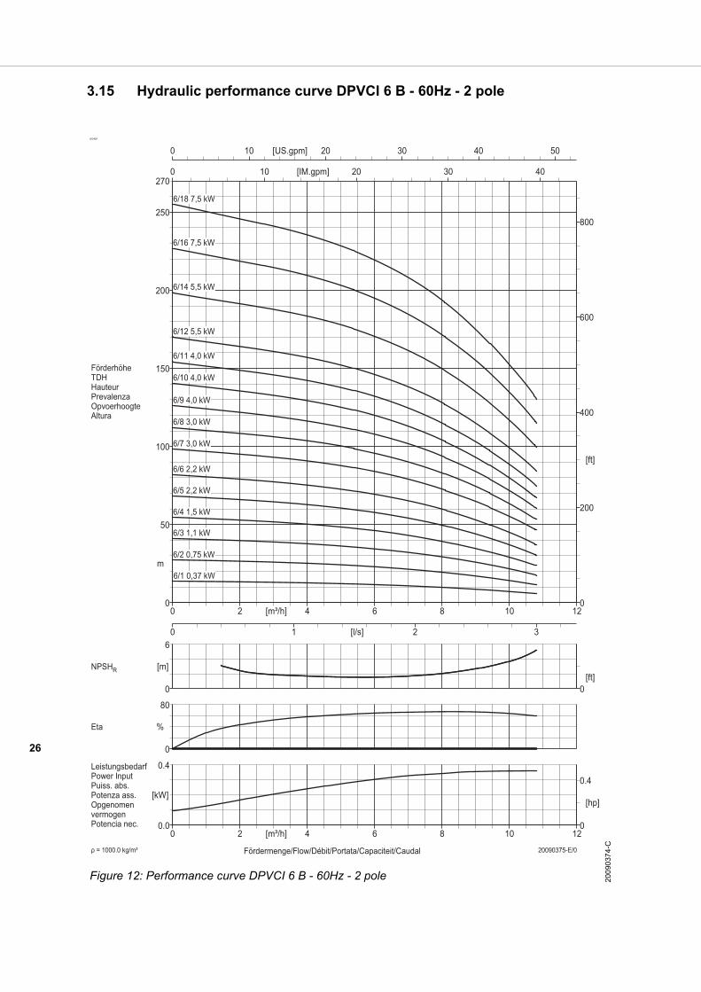
3.15 Hydraulic performance curve DPVCI 6 B - 60Hz - 2 pole
ID3425
Figure 12: Performance curve DPVCI 6 B - 60Hz - 2 pole 200
9037
4-C
27
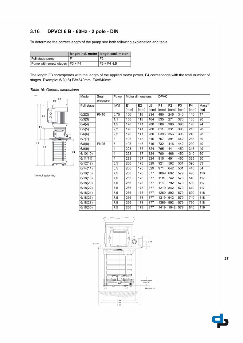
3.16 DPVCI 6 B - 60Hz - 2 pole - DIN
To determine the correct length of the pump see both following explanation and table.
The length F3 corresponds with the length of the applied motor power. F4 corresponds with the total number of stages. Example: 6/2(18) F3=340mm, F4=540mm. Table 16: General dimensions
length incl. motor length excl. motor
Full stage pump F1 F2
Pump with empty stages F3 + F4 F3 + F4 -LB
ID3436
*including packing
Model Seal pressure
Power Motor dimensions DPVCI
Full stage [kW] E1 [mm]
E2 [mm]
LB [mm]
F1 [mm]
F2 [mm]
F3 [mm]
F4 [mm]
Mass* [kg]
6/2(2) PN10 0,75 150 115 234 480 246 340 140 17
6/3(3) 1,1 150 115 164 535 271 370 165 20
6/4(4) 1,5 176 141 280 586 306 396 190 24
6/5(5) 2,2 176 141 280 611 331 396 215 28
6/6(6) 2,2 176 141 280 6396 356 396 240 28
6/7(7) 3 195 145 316 707 391 442 265 39
6/8(8) PN25 3 195 145 316 732 416 442 290 40
6/9(9) 4 223 167 324 765 441 450 315 49
6/10(10) 4 223 167 324 790 466 450 340 50
6/11(11) 4 223 167 324 815 491 450 365 50
6/12(12) 5,5 266 178 329 921 592 531 390 83
6/14(14) 5,5 266 178 329 971 642 531 440 84
6/16(16) 7,5 266 178 377 1069 692 579 490 116
6/18(18) 7,5 266 178 377 1119 742 579 540 117
6/18(20) 7,5 266 178 377 1169 792 579 590 117
6/18(22) 7,5 266 178 377 1219 842 579 640 117
6/18(24) 7,5 266 178 377 1269 892 579 690 118
6/18(26) 7,5 266 178 377 1319 942 579 740 118
6/18(28) 7,5 266 178 377 1369 992 579 790 118
6/18(30) 7,5 266 178 377 1419 1042 579 840 119
28
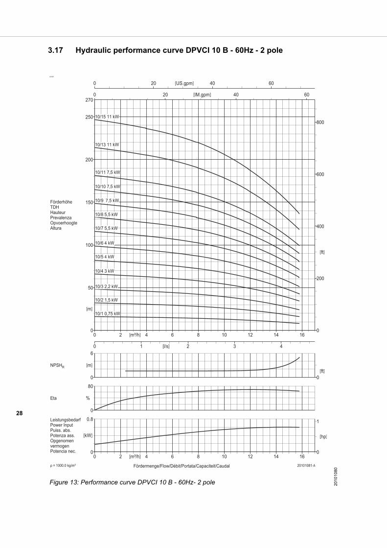
3.17 Hydraulic performance curve DPVCI 10 B - 60Hz - 2 pole
ID3425
Figure 13: Performance curve DPVCI 10 B - 60Hz- 2 pole 2010
1080

29
3.18 DPVCI 10 B - 60Hz - 2 pole - DIN
To determine the correct length of the pump see both following explanation and table.
The length F3 corresponds with the length of the applied motor power. F4 corresponds with the total number of stages. Example: 10/1(6) F3=343mm, F4=287mm. Table 17: General dimensions
length incl. motor length excl. motor
Full stage pump F1 F2
Pump with empty stages F3 + F4 F3 + F4 -LB
ID3436
*including packing
Model Seal pres-sure
Power Motor dimensions DPVCI
Full stage [kW] E1 [mm]
E2 [mm]
LB [mm]
F1 [mm]
F2 [mm]
F3 [mm]
F4 [mm]
Mass* [kg]
10/1(2) PN10 0,75 150 115 234 497 263 343 154 17
10/2(2) 1,5 176 115 280 553 273 399 154 30
10/3(3) 2,2 176 115 280 580 300 399 181 34
10/4(4) 3 195 141 316 652 336 445 207 45
10/5(5) 4 223 141 324 687 363 453 234 55
10/6(6) 4 223 141 324 740 416 453 287 56
10/7(7) PN25 5,5 266 178 329 826 497 539 287 71
10/8(8) 5,5 266 178 329 852 523 539 313 72
10/9(9) 7,5 266 178 377 926 549 587 339 119
10/10(10) 7,5 266 178 377 953 576 587 366 120
10/11(11) 7,5 266 178 377 979 602 587 392 121
10/13(13) 11 315 204 498 1183 685 738 445 178
10/15(15) 11 315 204 498 1236 738 738 498 179
10/15(17) 11 315 204 498 1289 791 738 551 183
10/15(19) 11 315 204 498 1342 844 738 604 184
10/15(21) 11 315 204 498 1395 897 738 657 184

30
3.19 Hydraulic performance curve DPVCI 15 B - 60Hz - 2 pole
ID3425
Figure 14: Performance curve DPVCI 15 B - 60Hz - 2 pole 201
0108
4
31
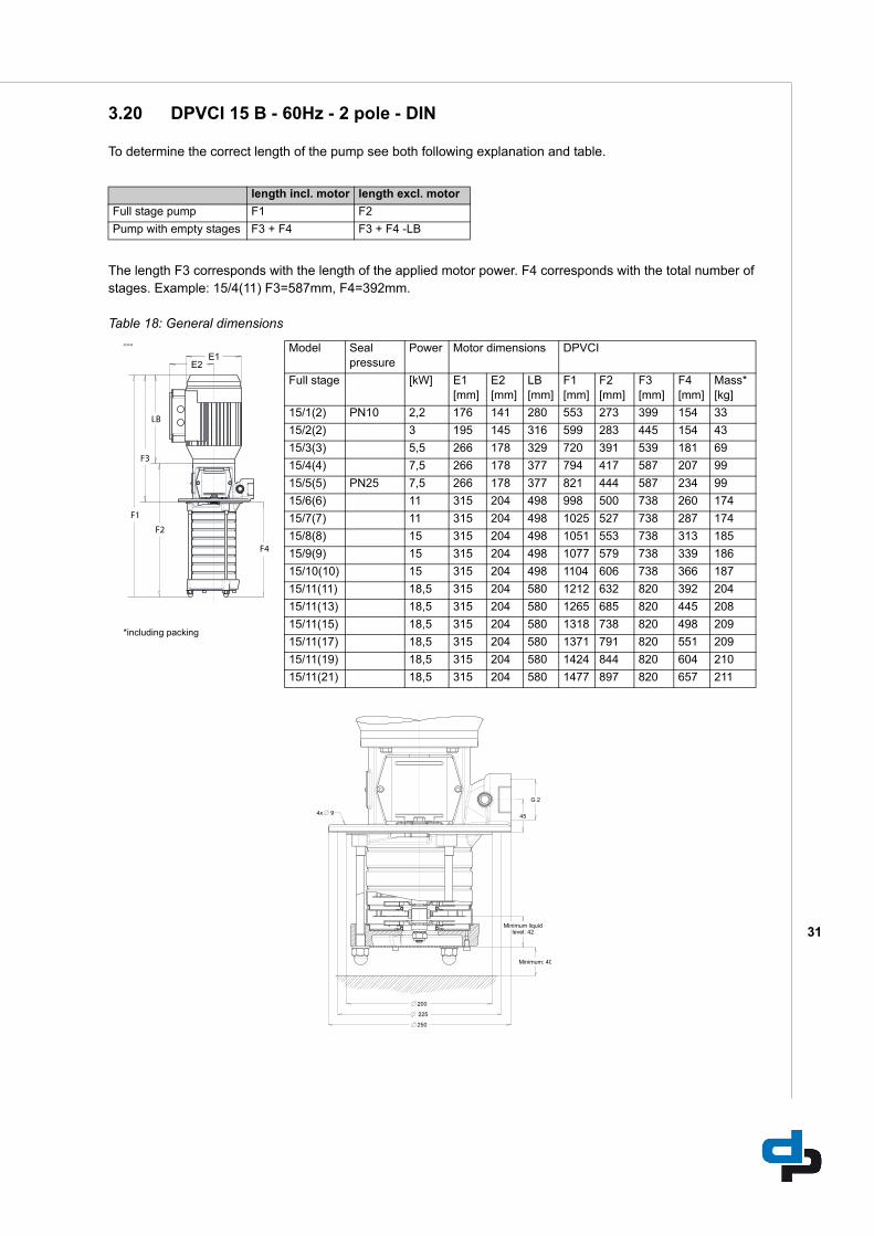
3.20 DPVCI 15 B - 60Hz - 2 pole - DIN
To determine the correct length of the pump see both following explanation and table.
The length F3 corresponds with the length of the applied motor power. F4 corresponds with the total number of stages. Example: 15/4(11) F3=587mm, F4=392mm. Table 18: General dimensions
length incl. motor length excl. motor
Full stage pump F1 F2
Pump with empty stages F3 + F4 F3 + F4 -LB
ID3436
*including packing
Model Seal pressure
Power Motor dimensions DPVCI
Full stage [kW] E1 [mm]
E2 [mm]
LB [mm]
F1 [mm]
F2 [mm]
F3 [mm]
F4 [mm]
Mass* [kg]
15/1(2) PN10 2,2 176 141 280 553 273 399 154 33
15/2(2) 3 195 145 316 599 283 445 154 43
15/3(3) 5,5 266 178 329 720 391 539 181 69
15/4(4) 7,5 266 178 377 794 417 587 207 99
15/5(5) PN25 7,5 266 178 377 821 444 587 234 99
15/6(6) 11 315 204 498 998 500 738 260 174
15/7(7) 11 315 204 498 1025 527 738 287 174
15/8(8) 15 315 204 498 1051 553 738 313 185
15/9(9) 15 315 204 498 1077 579 738 339 186
15/10(10) 15 315 204 498 1104 606 738 366 187
15/11(11) 18,5 315 204 580 1212 632 820 392 204
15/11(13) 18,5 315 204 580 1265 685 820 445 208
15/11(15) 18,5 315 204 580 1318 738 820 498 209
15/11(17) 18,5 315 204 580 1371 791 820 551 209
15/11(19) 18,5 315 204 580 1424 844 820 604 210
15/11(21) 18,5 315 204 580 1477 897 820 657 211

32
4 Seals
4.1 Mechanical seal option specifications
Table 19: Seal code, dimensions according EN24960
*default seal type, code depends on max pump pressure
Sh
aft
sea
l Ty
pe
Mat
eri
al m
ech
anic
al
sea
l
Sea
l co
de
Mat
eri
al s
haf
t se
al
Mat
eri
al p
um
pel
asto
mer
Tem
per
atu
re r
ang
e sh
aft
seal
[oC
]
Max
. pre
ssu
re [
bar
]
Car
trid
ge
MG-G60 B Q1 E GG 11 Ca / SiC / EPDM * EPDM -20 - 100 10
MG-G60 B Q1 V GG 12 Ca / SiC / Viton Viton -20 - 120 10
RMG-G606 Q1 B E GG 13 SiC / Ca / EPDM EPDM WRAS / ACS -20 - 100 25
RMG-G606 Q1 B V GG 14 SiC / Ca / Viton Viton -20 - 120 (140) 25 (16)
RMG-G606 U3 U3 X4 GG 15 TuC / TuC / HNBR HNBR -20 - 120 (140) 25 (16)
RMG-G606 U3 U3 V GG 16 TuC / TuC / Viton Viton -20 - 120 25
RMG-G606 U3 B E GG 18 TuC / Ca / EPDM EPDM 559236 -20 - 120 (140) 25 (16)
RMG-G606 Q1 B E GG 23 SiC / Ca / EPDM EPDM -20 - 100 25
MG-G606 Q1 Q1 V GG 24 SiC / SiC /Viton Viton -20 - 120 10
MG-G606 Q1 Q1 X4 GG 28 SiC / SiC/ HNBR HNBR -20 - 120 10
MG-G606 Q1 Q1 E GG 29 SiC / SiC / EPDM EPDM -20 - 100 10
33
5 Motors and motor options
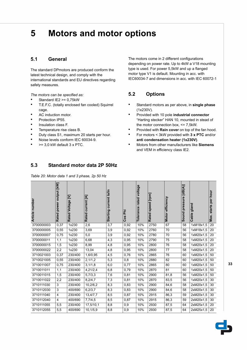
5.1 General
The standard DPmotors are produced conform the latest technical design, and comply with the international standards and EU directives regarding safety measures.
The motors can be specified as:• Standard IE2 >= 0,75kW• T.E.F.C. (totally enclosed fan cooled) Squirrel
cage.• AC induction motor.• Protection IP55.• Insulation class F.• Temperature rise class B.• Duty class S1, maximum 20 starts per hour.• Noise levels conform IEC 60034-9.• >= 3,0 kW default 3 x PTC.
The motors come in 2 different configurations depending on power rate. Up to 4kW a V18 mounting type is used. For power 5,5kW and up a flanged motor type V1 is default. Mounting in acc. with IEC60034-7 and dimensions in acc. with IEC 60072-1
5.2 Options
• Standard motors as per above, in single phase (1x230V).
• Provided with 10 pole industrial connector “Harting stecker” HAN 10, mounted in stead of the motor connection box, <= 7,5kW.
• Provided with Rain cover on top of the fan hood.• For motors < 3kW provided with 3 x PTC and/or
anti condensation heater (1x230V).• Motors from other manufacturers like Siemens
and VEM in efficiency class IE2.
5.3 Standard motor data 2P 50Hz
Table 20: Motor data 1 and 3 phase, 2p 50 Hz
Art
icle
nu
mb
er
Rat
ed p
ow
er o
utp
ut
[kW
]
Rat
ed V
olt
age
[V]
Rat
ed c
urr
ent
[A]
Sta
rtin
g c
urr
ent
Ia/In
Co
s P
hi
Tole
ran
ce r
ated
vo
ltag
e
Rat
ed s
pee
d [
rpm
]
Mo
tor
effi
cien
cy
So
un
d p
ress
ure
[d
B(A
)]
Cab
le g
lan
d
Max
. sta
rts
per
ho
ur
3700000003 0,37 1x230 2,6 3,7 0,92 10% 2750 67 58 1xM18x1,5 20
3700000005 0,55 1x230 3,69 3,9 0,92 10% 2760 70 56 1xM18x1,5 20
3700000007 0,75 1x230 5,0 3,9 0,92 10% 2780 70 56 1xM20x1,5 20
3700000011 1,1 1x230 6,68 4,3 0,95 10% 2790 75 58 1xM20x1,5 20
3700000015 1,5 1x230 8,99 4,8 0,95 10% 2800 76 58 1xM20x1,5 20
3700000022 2,2 1x230 13,04 4,8 0,95 10% 2800 77 58 1xM20x1,5 20
3710021003 0,37 230/400 1,6/0,95 4,5 0,76 10% 2865 76 60 1xM20x1,5 50
3710021005 0,55 230/400 2,1/1,2 5,3 0,8 10% 2880 82 60 1xM20x1,5 50
3710011007 0,75 230/400 3,1/1,8 6,0 0,77 10% 2865 80 60 1xM20x1,5 50
3710011011 1,1 230/400 4,21/2,4 6,8 0,79 10% 2870 81 60 1xM20x1,5 50
3710011015 1,5 230/400 5,7/3,3 7,6 0,81 10% 2900 81,8 56 1xM20x1,5 50
3710011022 2,2 230/400 8,2/4,7 7,3 0,81 10% 2870 83,5 56 1xM20x1,5 30
3710111030 3 230/400 10,2/6,2 8,3 0,83 10% 2900 84,6 58 2xM20x1,5 30
3710112030 3 400/690 6,2/3,7 8,3 0,83 10% 2900 84,6 58 2xM20x1,5 30
3710111040 4 230/400 13,4/7,7 8,5 0,87 10% 2915 86,3 59 2xM20x1,5 30
3710112040 4 400/690 7,7/4,5 8,5 0,87 10% 2915 86,3 59 2xM20x1,5 30
3710111055 5,5 230/400 17,5/10,1 8,8 0,9 10% 2930 87,5 64 2xM25x1,5 20
3710112055 5,5 400/690 10,1/5,9 8,8 0,9 10% 2930 87,5 64 2xM25x1,5 20
34
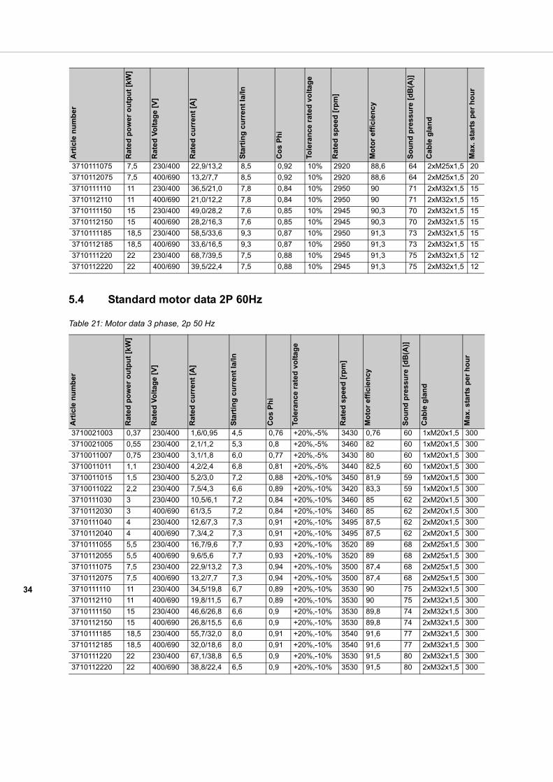
5.4 Standard motor data 2P 60Hz
Table 21: Motor data 3 phase, 2p 50 Hz
3710111075 7,5 230/400 22,9/13,2 8,5 0,92 10% 2920 88,6 64 2xM25x1,5 20
3710112075 7,5 400/690 13,2/7,7 8,5 0,92 10% 2920 88,6 64 2xM25x1,5 20
3710111110 11 230/400 36,5/21,0 7,8 0,84 10% 2950 90 71 2xM32x1,5 15
3710112110 11 400/690 21,0/12,2 7,8 0,84 10% 2950 90 71 2xM32x1,5 15
3710111150 15 230/400 49,0/28,2 7,6 0,85 10% 2945 90,3 70 2xM32x1,5 15
3710112150 15 400/690 28,2/16,3 7,6 0,85 10% 2945 90,3 70 2xM32x1,5 15
3710111185 18,5 230/400 58,5/33,6 9,3 0,87 10% 2950 91,3 73 2xM32x1,5 15
3710112185 18,5 400/690 33,6/16,5 9,3 0,87 10% 2950 91,3 73 2xM32x1,5 15
3710111220 22 230/400 68,7/39,5 7,5 0,88 10% 2945 91,3 75 2xM32x1,5 12
3710112220 22 400/690 39,5/22,4 7,5 0,88 10% 2945 91,3 75 2xM32x1,5 12
Art
icle
nu
mb
er
Rat
ed
po
wer
ou
tpu
t [k
W]
Rat
ed
Vo
ltag
e [V
]
Rat
ed
cu
rren
t [A
]
Sta
rtin
g c
urr
en
t Ia
/In
Co
s P
hi
Tole
ran
ce r
ated
vo
ltag
e
Rat
ed
sp
eed
[rp
m]
Mo
tor
effi
cien
cy
So
un
d p
ress
ure
[d
B(A
)]
Cab
le g
lan
d
Max
. sta
rts
per
ho
ur
Art
icle
nu
mb
er
Ra
ted
po
wer
ou
tpu
t [k
W]
Ra
ted
Vo
ltag
e [V
]
Ra
ted
cu
rren
t [A
]
Sta
rtin
g c
urr
ent
Ia/In
Co
s P
hi
Tole
ran
ce r
ated
vo
ltag
e
Ra
ted
sp
eed
[rp
m]
Mo
tor
effi
cien
cy
So
un
d p
ress
ure
[d
B(A
)]
Ca
ble
gla
nd
Max
. st
arts
pe
r h
ou
r
3710021003 0,37 230/400 1,6/0,95 4,5 0,76 +20%,-5% 3430 0,76 60 1xM20x1,5 300
3710021005 0,55 230/400 2,1/1,2 5,3 0,8 +20%,-5% 3460 82 60 1xM20x1,5 300
3710011007 0,75 230/400 3,1/1,8 6,0 0,77 +20%,-5% 3430 80 60 1xM20x1,5 300
3710011011 1,1 230/400 4,2/2,4 6,8 0,81 +20%,-5% 3440 82,5 60 1xM20x1,5 300
3710011015 1,5 230/400 5,2/3,0 7,2 0,88 +20%,-10% 3450 81,9 59 1xM20x1,5 300
3710011022 2,2 230/400 7,5/4,3 6,6 0,89 +20%,-10% 3420 83,3 59 1xM20x1,5 300
3710111030 3 230/400 10,5/6,1 7,2 0,84 +20%,-10% 3460 85 62 2xM20x1,5 300
3710112030 3 400/690 61/3,5 7,2 0,84 +20%,-10% 3460 85 62 2xM20x1,5 300
3710111040 4 230/400 12,6/7,3 7,3 0,91 +20%,-10% 3495 87,5 62 2xM20x1,5 300
3710112040 4 400/690 7,3/4,2 7,3 0,91 +20%,-10% 3495 87,5 62 2xM20x1,5 300
3710111055 5,5 230/400 16,7/9,6 7,7 0,93 +20%,-10% 3520 89 68 2xM25x1,5 300
3710112055 5,5 400/690 9,6/5,6 7,7 0,93 +20%,-10% 3520 89 68 2xM25x1,5 300
3710111075 7,5 230/400 22,9/13,2 7,3 0,94 +20%,-10% 3500 87,4 68 2xM25x1,5 300
3710112075 7,5 400/690 13,2/7,7 7,3 0,94 +20%,-10% 3500 87,4 68 2xM25x1,5 300
3710111110 11 230/400 34,5/19,8 6,7 0,89 +20%,-10% 3530 90 75 2xM32x1,5 300
3710112110 11 400/690 19,8/11,5 6,7 0,89 +20%,-10% 3530 90 75 2xM32x1,5 300
3710111150 15 230/400 46,6/26,8 6,6 0,9 +20%,-10% 3530 89,8 74 2xM32x1,5 300
3710112150 15 400/690 26,8/15,5 6,6 0,9 +20%,-10% 3530 89,8 74 2xM32x1,5 300
3710111185 18,5 230/400 55,7/32,0 8,0 0,91 +20%,-10% 3540 91,6 77 2xM32x1,5 300
3710112185 18,5 400/690 32,0/18,6 8,0 0,91 +20%,-10% 3540 91,6 77 2xM32x1,5 300
3710111220 22 230/400 67,1/38,8 6,5 0,9 +20%,-10% 3530 91,5 80 2xM32x1,5 300
3710112220 22 400/690 38,8/22,4 6,5 0,9 +20%,-10% 3530 91,5 80 2xM32x1,5 300
35
6 Frequency drive
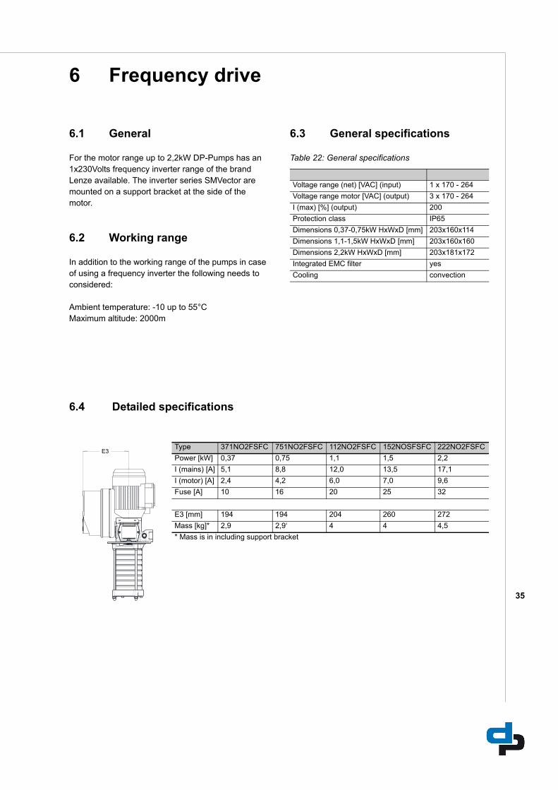
6.1 General
For the motor range up to 2,2kW DP-Pumps has an 1x230Volts frequency inverter range of the brand Lenze available. The inverter series SMVector are mounted on a support bracket at the side of the motor.
6.2 Working range
In addition to the working range of the pumps in case of using a frequency inverter the following needs to considered:
Ambient temperature: -10 up to 55°CMaximum altitude: 2000m
6.3 General specifications
Table 22: General specifications
6.4 Detailed specifications
Voltage range (net) [VAC] (input) 1 x 170 - 264
Voltage range motor [VAC] (output) 3 x 170 - 264
I (max) [%] (output) 200
Protection class IP65
Dimensions 0,37-0,75kW HxWxD [mm] 203x160x114
Dimensions 1,1-1,5kW HxWxD [mm] 203x160x160
Dimensions 2,2kW HxWxD [mm] 203x181x172
Integrated EMC filter yes
Cooling convection
Type 371NO2FSFC 751NO2FSFC 112NO2FSFC 152NOSFSFC 222NO2FSFC
Power [kW] 0,37 0,75 1,1 1,5 2,2
I (mains) [A] 5,1 8,8 12,0 13,5 17,1
I (motor) [A] 2,4 4,2 6,0 7,0 9,6
Fuse [A] 10 16 20 25 32
E3 [mm] 194 194 204 260 272
Mass [kg]* 2,9 2,9‘ 4 4 4,5
* Mass is in including support bracket
36
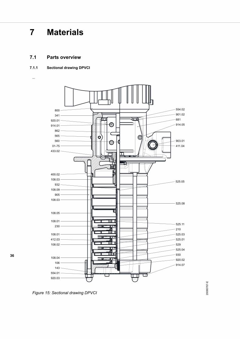
7 Materials
7.1 Parts overview
7.1.1 Sectional drawing DPVCI
ID3414
Figure 15: Sectional drawing DPVCI 200
8076
7-E
920.01
914.01
560
433.02
01-75
565
554.02
901.02
681
914.05
903.01
411.04
108.03
108.09
108.03
108.05
108.01
108.01
108.02
108.04
230
905
400.02
106
554.01
920.03
914.07
920.02
525.04
529
525.01
525.03
210
412.03
525.11
341
800
862
932
143
930
525.08
525.05
37
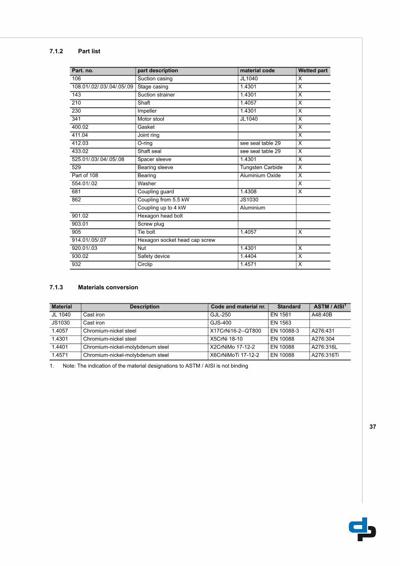
7.1.2 Part list
7.1.3 Materials conversion
Part. no. part description material code Wetted part
106 Suction casing JL1040 X
108.01/.02/.03/.04/.05/.09 Stage casing 1.4301 X
143 Suction strainer 1.4301 X
210 Shaft 1.4057 X
230 Impeller 1.4301 X
341 Motor stool JL1040 X
400.02 Gasket X
411.04 Joint ring X
412.03 O-ring see seal table 29 X
433.02 Shaft seal see seal table 29 X
525.01/.03/.04/.05/.08 Spacer sleeve 1.4301 X
529 Bearing sleeve Tungsten Carbide X
Part of 108 Bearing Aluminium Oxide X
554.01/.02 Washer X
681 Coupling guard 1.4308 X
862 Coupling from 5.5 kW JS1030
Coupling up to 4 kW Aluminium
901.02 Hexagon head bolt
903.01 Screw plug
905 Tie bolt 1.4057 X
914.01/.05/.07 Hexagon socket head cap screw
920.01/.03 Nut 1.4301 X
930.02 Safety device 1.4404 X
932 Circlip 1.4571 X
Material Description Code and material nr. Standard ASTM / AISI1
JL 1040 Cast iron GJL-250 EN 1561 A48:40B
JS1030 Cast iron GJS-400 EN 1563
1.4057 Chromium-nickel steel X17CrNi16-2--QT800 EN 10088-3 A276:431
1.4301 Chromium-nickel steel X5CrNi 18-10 EN 10088 A276:304
1.4401 Chromium-nickel-molybdenum steel X2CrNiMo 17-12-2 EN 10088 A276:316L
1.4571 Chromium-nickel-molybdenum steel X6CrNiMoTi 17-12-2 EN 10088 A276:316Ti
1. Note: The indication of the material designations to ASTM / AISI is not binding
38
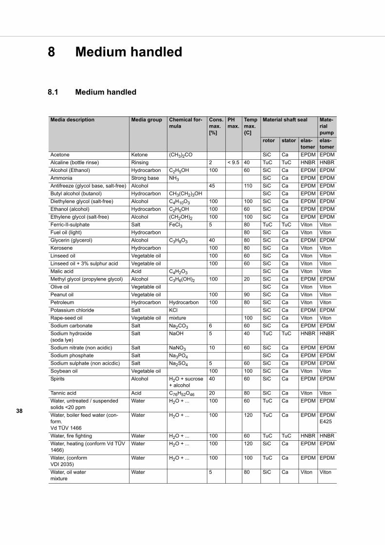
8 Medium handled
8.1 Medium handled
Media description Media group Chemical for-mula
Cons. max. [%]
PH max.
Temp max. {C]
Material shaft seal Mate-rial pump
rotor stator elas-tomer
elas-tomer
Acetone Ketone (CH3)2CO SiC Ca EPDM EPDM
Alcaline (bottle rinse) Rinsing 2 < 9.5 40 TuC TuC HNBR HNBR
Alcohol (Ethanol) Hydrocarbon C2H5OH 100 60 SiC Ca EPDM EPDM
Ammonia Strong base NH3 SiC Ca EPDM EPDM
Antifreeze (glycol base, salt-free) Alcohol 45 110 SiC Ca EPDM EPDM
Butyl alcohol (butanol) Hydrocarbon CH3(CH2)3OH SiC Ca EPDM EPDM
Diethylene glycol (salt-free) Alcohol C4H10O3 100 100 SiC Ca EPDM EPDM
Ethanol (alcohol) Hydrocarbon C2H5OH 100 60 SiC Ca EPDM EPDM
Ethylene glycol (salt-free) Alcohol (CH2OH)2 100 100 SiC Ca EPDM EPDM
Ferric-II-sulphate Salt FeCl3 5 80 TuC TuC Viton Viton
Fuel oil (light) Hydrocarbon 80 SiC Ca Viton Viton
Glycerin (glycerol) Alcohol C3H8O3 40 80 SiC Ca EPDM EPDM
Kerosene Hydrocarbon 100 80 SiC Ca Viton Viton
Linseed oil Vegetable oil 100 60 SiC Ca Viton Viton
Linseed oil + 3% sulphur acid Vegetable oil 100 60 SiC Ca Viton Viton
Malic acid Acid C4H2O3 SiC Ca Viton Viton
Methyl glycol (propylene glycol) Alcohol C3H6(OH)2 100 20 SiC Ca EPDM EPDM
Olive oil Vegetable oil SiC Ca Viton Viton
Peanut oil Vegetable oil 100 90 SiC Ca Viton Viton
Petroleum Hydrocarbon Hydrocarbon 100 80 SiC Ca Viton Viton
Potassium chloride Salt KCl SiC Ca EPDM EPDM
Rape-seed oil Vegetable oil mixture 100 SiC Ca Viton Viton
Sodium carbonate Salt Na2CO3 6 60 SiC Ca EPDM EPDM
Sodium hydroxide (soda lye)
Salt NaOH 5 40 TuC TuC HNBR HNBR
Sodium nitrate (non acidic) Salt NaNO3 10 60 SiC Ca EPDM EPDM
Sodium phosphate Salt Na3PO4 SiC Ca EPDM EPDM
Sodium sulphate (non acicdic) Salt Na2SO4 5 60 SiC Ca EPDM EPDM
Soybean oil Vegetable oil 100 100 SiC Ca Viton Viton
Spirits Alcohol H2O + sucrose + alcohol
40 60 SiC Ca EPDM EPDM
Tannic acid Acid C76H52O46 20 80 SiC Ca Viton Viton
Water, untreated / suspended solids <20 ppm
Water H2O + ... 100 60 TuC Ca EPDM EPDM
Water, boiler feed water (con-form. Vd TÜV 1466
Water H2O + ... 100 120 TuC Ca EPDM EPDME425
Water, fire fighting Water H2O + ... 100 60 TuC TuC HNBR HNBR
Water, heating (conform Vd TÜV 1466)
Water H2O + ... 100 120 SiC Ca EPDM EPDM
Water, (conform VDI 2035)
Water H2O + ... 100 100 TuC Ca EPDM EPDM
Water, oil water mixture
Water 5 80 SiC Ca Viton Viton
39
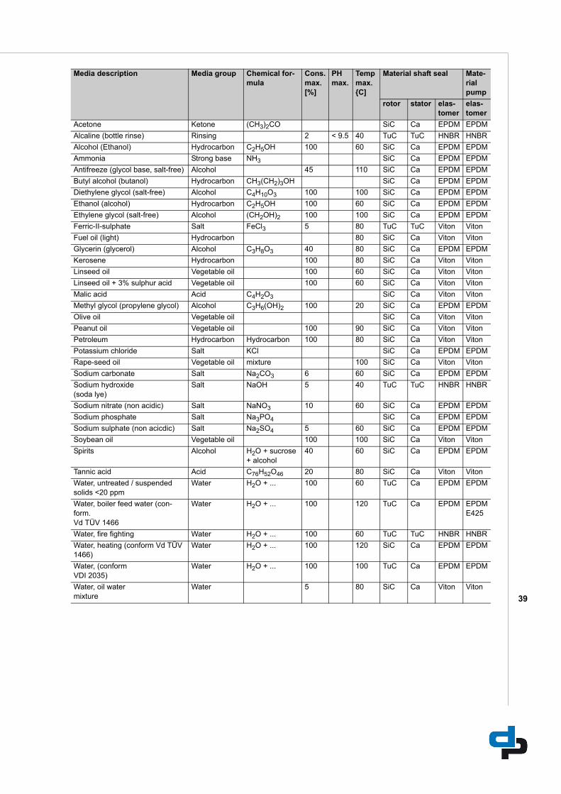
Acetone Ketone (CH3)2CO SiC Ca EPDM EPDM
Alcaline (bottle rinse) Rinsing 2 < 9.5 40 TuC TuC HNBR HNBR
Alcohol (Ethanol) Hydrocarbon C2H5OH 100 60 SiC Ca EPDM EPDM
Ammonia Strong base NH3 SiC Ca EPDM EPDM
Antifreeze (glycol base, salt-free) Alcohol 45 110 SiC Ca EPDM EPDM
Butyl alcohol (butanol) Hydrocarbon CH3(CH2)3OH SiC Ca EPDM EPDM
Diethylene glycol (salt-free) Alcohol C4H10O3 100 100 SiC Ca EPDM EPDM
Ethanol (alcohol) Hydrocarbon C2H5OH 100 60 SiC Ca EPDM EPDM
Ethylene glycol (salt-free) Alcohol (CH2OH)2 100 100 SiC Ca EPDM EPDM
Ferric-II-sulphate Salt FeCl3 5 80 TuC TuC Viton Viton
Fuel oil (light) Hydrocarbon 80 SiC Ca Viton Viton
Glycerin (glycerol) Alcohol C3H8O3 40 80 SiC Ca EPDM EPDM
Kerosene Hydrocarbon 100 80 SiC Ca Viton Viton
Linseed oil Vegetable oil 100 60 SiC Ca Viton Viton
Linseed oil + 3% sulphur acid Vegetable oil 100 60 SiC Ca Viton Viton
Malic acid Acid C4H2O3 SiC Ca Viton Viton
Methyl glycol (propylene glycol) Alcohol C3H6(OH)2 100 20 SiC Ca EPDM EPDM
Olive oil Vegetable oil SiC Ca Viton Viton
Peanut oil Vegetable oil 100 90 SiC Ca Viton Viton
Petroleum Hydrocarbon Hydrocarbon 100 80 SiC Ca Viton Viton
Potassium chloride Salt KCl SiC Ca EPDM EPDM
Rape-seed oil Vegetable oil mixture 100 SiC Ca Viton Viton
Sodium carbonate Salt Na2CO3 6 60 SiC Ca EPDM EPDM
Sodium hydroxide (soda lye)
Salt NaOH 5 40 TuC TuC HNBR HNBR
Sodium nitrate (non acidic) Salt NaNO3 10 60 SiC Ca EPDM EPDM
Sodium phosphate Salt Na3PO4 SiC Ca EPDM EPDM
Sodium sulphate (non acicdic) Salt Na2SO4 5 60 SiC Ca EPDM EPDM
Soybean oil Vegetable oil 100 100 SiC Ca Viton Viton
Spirits Alcohol H2O + sucrose + alcohol
40 60 SiC Ca EPDM EPDM
Tannic acid Acid C76H52O46 20 80 SiC Ca Viton Viton
Water, untreated / suspended solids <20 ppm
Water H2O + ... 100 60 TuC Ca EPDM EPDM
Water, boiler feed water (con-form. Vd TÜV 1466
Water H2O + ... 100 120 TuC Ca EPDM EPDME425
Water, fire fighting Water H2O + ... 100 60 TuC TuC HNBR HNBR
Water, heating (conform Vd TÜV 1466)
Water H2O + ... 100 120 SiC Ca EPDM EPDM
Water, (conform VDI 2035)
Water H2O + ... 100 100 TuC Ca EPDM EPDM
Water, oil water mixture
Water 5 80 SiC Ca Viton Viton
Media description Media group Chemical for-mula
Cons. max. [%]
PH max.
Temp max. {C]
Material shaft seal Mate-rial pump
rotor stator elas-tomer
elas-tomer
dp pumps
P.O. Box 282400 AA Alphen aan den RijnThe Netherlands
t +31 172 48 83 88f +31 172 46 89 30
03/2013
Original instructions
97004475
Subject to modifications. Digital alteration, publication or distribution of the content of this document without prior notice is strictly prohibited.
Permission for use, copying and distribution of this document as published by DP-Pumps is granted on the condition that no part of the
document is used for information or commercial purposes outside of the DP-Pumps organisation or one of its recognised dealerships.