Embed Size (px)
Citation preview
STRUCTURES GROUP
DRAFTING GUIDELINES
FOR CONSULTANTS
Transport Services Division
STRUCTURES Standards & Guidelines
K-Net Doc: 3051471 UNCONTROLLED COPY WHEN PRINTED Version No.: 4 Issue Date: 21/11/2011 Doc. Owner: Manager, Structures 1 of 23
DRAFTING GUIDELINES FOR CONSULTANTS
CONTENTS
1. Drawings
1.1. Drawing Sheets ......................................................................................................... 3
1.2. Orthogonal Projection ................................................................................................ 3
1.3. Line & Text Thickness ............................................................................................... 3
1.4. Types of Lines ........................................................................................................... 3
1.5. Dimensions ................................................................................................................ 4
1.6. Scale Ratios............................................................................................................... 4
1.7. Leader Lines .............................................................................................................. 4
1.8. Circle Centrelines ...................................................................................................... 5
1.9. Suffixes for Numerals in Text ..................................................................................... 5
1.10. Survey Marks ............................................................................................................. 5
1.11. North Arrows .............................................................................................................. 5
1.12. Surface Finish ............................................................................................................ 6
1.13. Titles for Views .......................................................................................................... 6
1.14. Note Blocks ............................................................................................................... 7
1.15. Notes on Views .......................................................................................................... 7
1.16. Gradients & Batters ................................................................................................... 8
2. Reinforced Concrete Detailing
2.1. Introduction ................................................................................................................ 9
2.2. Standard Cover Depths ............................................................................................. 9
2.3. Minimum Spacing of Parallel Bars ............................................................................. 9
2.4. Reinforcing Bar Sections Relative to Longitudinal Bars ............................................. 9
2.5. Notation ................................................................................................................... 10
2.6. Diagrammatic Representation of Bars ..................................................................... 11
2.7. Limit Lines in Skewed Elements .............................................................................. 12
2.8. Diagrammatic Representation of Mesh .................................................................... 12
DRAFTING GUIDELINES FOR CONSULTANTS
K-Net Doc: 3051471 UNCONTROLLED COPY WHEN PRINTED Version No.: 4 Issue Date: 21/11/2011 Doc. Owner: Manager, Structures 2 of 23
3. Structural Steel Detailing
3.1. Designation of Steel Elements ................................................................................. 13
3.2. Welding Symbols ..................................................................................................... 13
3.3. Bolt Holes ................................................................................................................ 13
3.4. Minimum Edge Distances to Hole Centreline (mm) ................................................. 13
3.5. Bolts ......................................................................................................................... 13
3.5.1. Designation ............................................................................................................. 13 3.6. Annotation on Drawing ............................................................................................ 14
3.7. Details in Notes ........................................................................................................ 14
4. Locality Plans
4.1. Urban Location ........................................................................................................ 15
4.2. Rural Location.......................................................................................................... 16
5. Cad Information
5.1. Template .................................................................................................................. 17
5.2. File Names .............................................................................................................. 17
5.3. Text Styles ............................................................................................................... 17
5.4. Dimensions .............................................................................................................. 17
5.5. Layer Names ........................................................................................................... 18
6. Bridge Plaque and Recess Details Drawing
6.1. Elevation and detail of plaque and recess detail ...................................................... 19
7. Structures Group Autocad Blocks Supplied
7.1. Description for use of blocks supplied ..................................................................... 19
7.2. Bar Marks and Text ................................................................................................. 20
7.2.1. Editable Reinforcement Bar Marks and Text ........................................................... 20 7.3. Centreline Text ........................................................................................................ 21
7.4. Titles for Sections, Elevations, Details and Views ................................................... 21
7.5. Beaks ....................................................................................................................... 22
7.5.1. Section beaks and detail hexagons ......................................................................... 22
Revision Status
Revision Date Pages Details Authorised
1 06-Dec-00 1–26 First issue P. Gunn
2 03-Jun-08 1–22 Revision 2 P. Gunn
3 20-July-11 1-23 Revision 3 P. Gunn
4 21-Nov-11 1-23 Revision 4 P. Gunn
Drawings DRAFTING GUIDELINES FOR CONSULTANTS
K-Net Doc: 3051471 UNCONTROLLED COPY WHEN PRINTED Version No.: 4 Issue Date: 21/11/2011 Doc. Owner: Manager, Structures 3 of 23
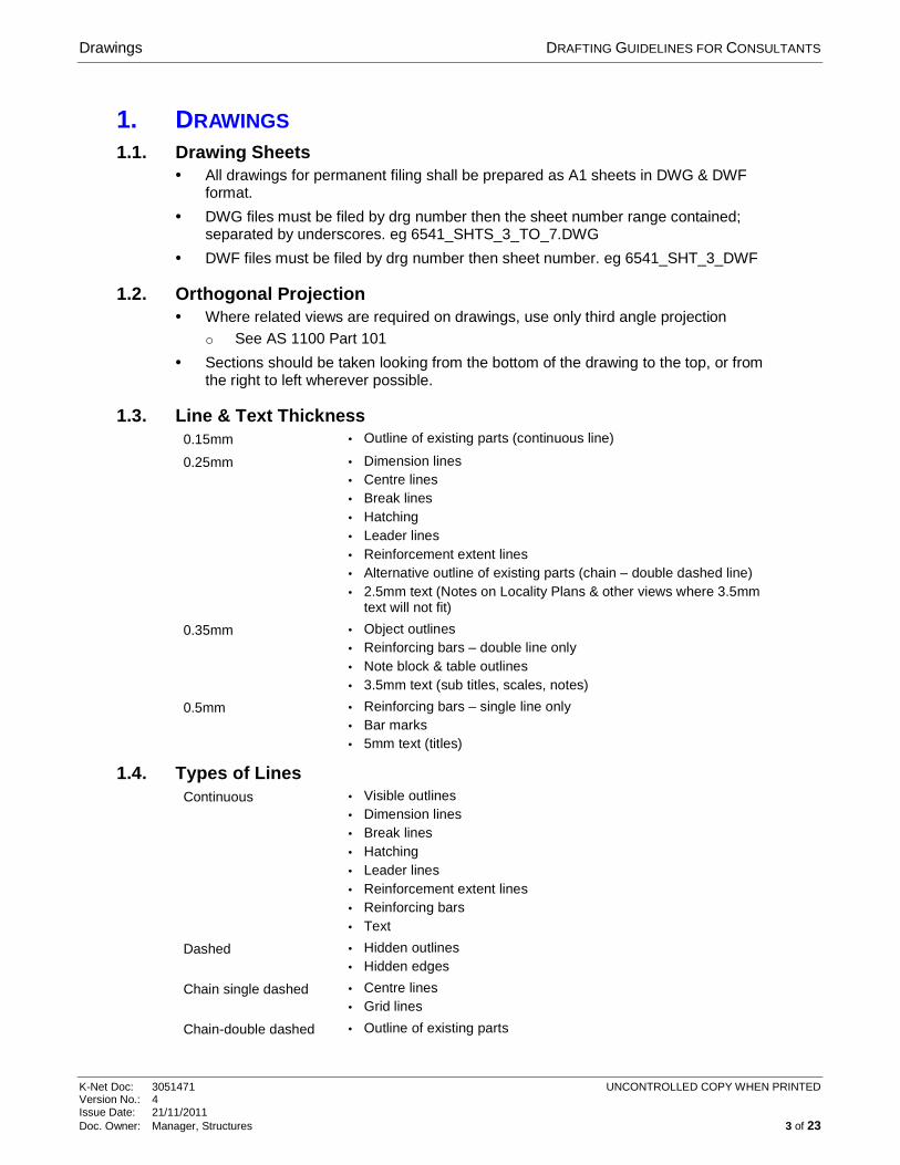
1. DRAWINGS 1.1. Drawing Sheets
• All drawings for permanent filing shall be prepared as A1 sheets in DWG & DWF format.
• DWG files must be filed by drg number then the sheet number range contained; separated by underscores. eg 6541_SHTS_3_TO_7.DWG
• DWF files must be filed by drg number then sheet number. eg 6541_SHT_3_DWF
1.2. Orthogonal Projection • Where related views are required on drawings, use only third angle projection
o See AS 1100 Part 101
• Sections should be taken looking from the bottom of the drawing to the top, or from the right to left wherever possible.
1.3. Line & Text Thickness 0.15mm • Outline of existing parts (continuous line)
0.25mm • Dimension lines • Centre lines • Break lines • Hatching • Leader lines • Reinforcement extent lines • Alternative outline of existing parts (chain – double dashed line) • 2.5mm text (Notes on Locality Plans & other views where 3.5mm
text will not fit)
0.35mm • Object outlines • Reinforcing bars – double line only • Note block & table outlines • 3.5mm text (sub titles, scales, notes)
0.5mm • Reinforcing bars – single line only • Bar marks • 5mm text (titles)
1.4. Types of Lines Continuous • Visible outlines
• Dimension lines • Break lines • Hatching • Leader lines • Reinforcement extent lines • Reinforcing bars • Text
Dashed • Hidden outlines • Hidden edges
Chain single dashed • Centre lines • Grid lines
Chain-double dashed • Outline of existing parts
Drawings DRAFTING GUIDELINES FOR CONSULTANTS
K-Net Doc: 3051471 UNCONTROLLED COPY WHEN PRINTED Version No.: 4 Issue Date: 21/11/2011 Doc. Owner: Manager, Structures 4 of 23
1.5. Dimensions • Linear dimensions shall be in millimetres but not marked 'mm' because drawing sheet
shall have note above bottom border as follows: ALL DIMENSIONS ARE IN MILLIMETRES UNLESS SHOWN OTHERWISE
• Reduced levels & chainages shall be in metres & shown thus: RL 34.955m CH 810.000m
• Angles shall be in decimal parts of degrees e.g. 67.25º
• Dimensioning symbols shall prefix the dimension e.g. Ø 50 R 25
• No more dimensions than those necessary for complete definition of an object shall be given
• Dimension text height shall be 3.5mm
1.6. Scale Ratios • Every effort should be made to use the recommended scale ratios in AS 1100
Part 101, as shown below. Non-standard scale ratios should be marked 'NOT TO SCALE'
1:1 1:2 1:5
1:10 1:20 1:25 1:50
1:100 1:125 1:200 1:250 1:500
1:1000 1:2000 1:5000
• Different scales on one sheet should be kept to a minimum with all scales clearly
indicated.
• Indication of scale ratios: See Titles for Views
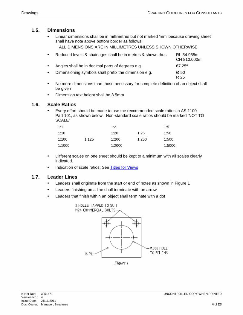
1.7. Leader Lines • Leaders shall originate from the start or end of notes as shown in Figure 1
• Leaders finishing on a line shall terminate with an arrow
• Leaders that finish within an object shall terminate with a dot
Figure 1
Drawings DRAFTING GUIDELINES FOR CONSULTANTS
K-Net Doc: 3051471 UNCONTROLLED COPY WHEN PRINTED Version No.: 4 Issue Date: 21/11/2011 Doc. Owner: Manager, Structures 5 of 23
1.8. Circle Centrelines • All centrelines to be in 0.25 pen
o Large circles in centreline linetype o Small circles in full linetype
• Refer to Figure 1 above
1.9. Suffixes for Numerals in Text • In Note blocks ALWAYS use mm suffix.
• In annotation on drawing DO NOT use mm suffix e.g. o 25 CHAMFER o 2 BOLTS, M16 o 4 HOLES, Ø 30 o 12 PL o 100x8 FL o Ø 30x300 LONG SHEAR PIN o 100x20 NEOPRENE BEARING STRIP
1.10. Survey Marks • Permanent Bench Marks � BM
• Temporary Bench Marks O TBM
• Metal Pins � MP
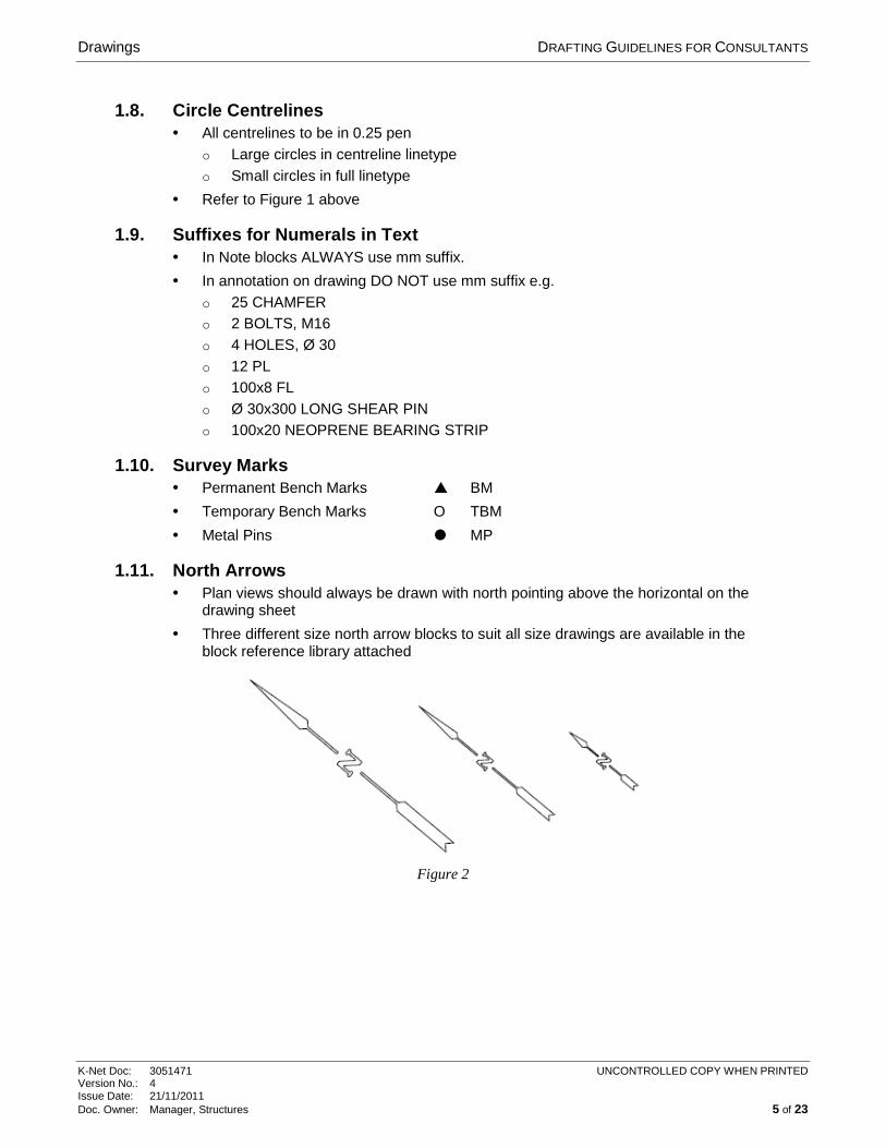
1.11. North Arrows • Plan views should always be drawn with north pointing above the horizontal on the
drawing sheet
• Three different size north arrow blocks to suit all size drawings are available in the block reference library attached
Figure 2
Drawings DRAFTING GUIDELINES FOR CONSULTANTS
K-Net Doc: 3051471 UNCONTROLLED COPY WHEN PRINTED Version No.: 4 Issue Date: 21/11/2011 Doc. Owner: Manager, Structures 6 of 23
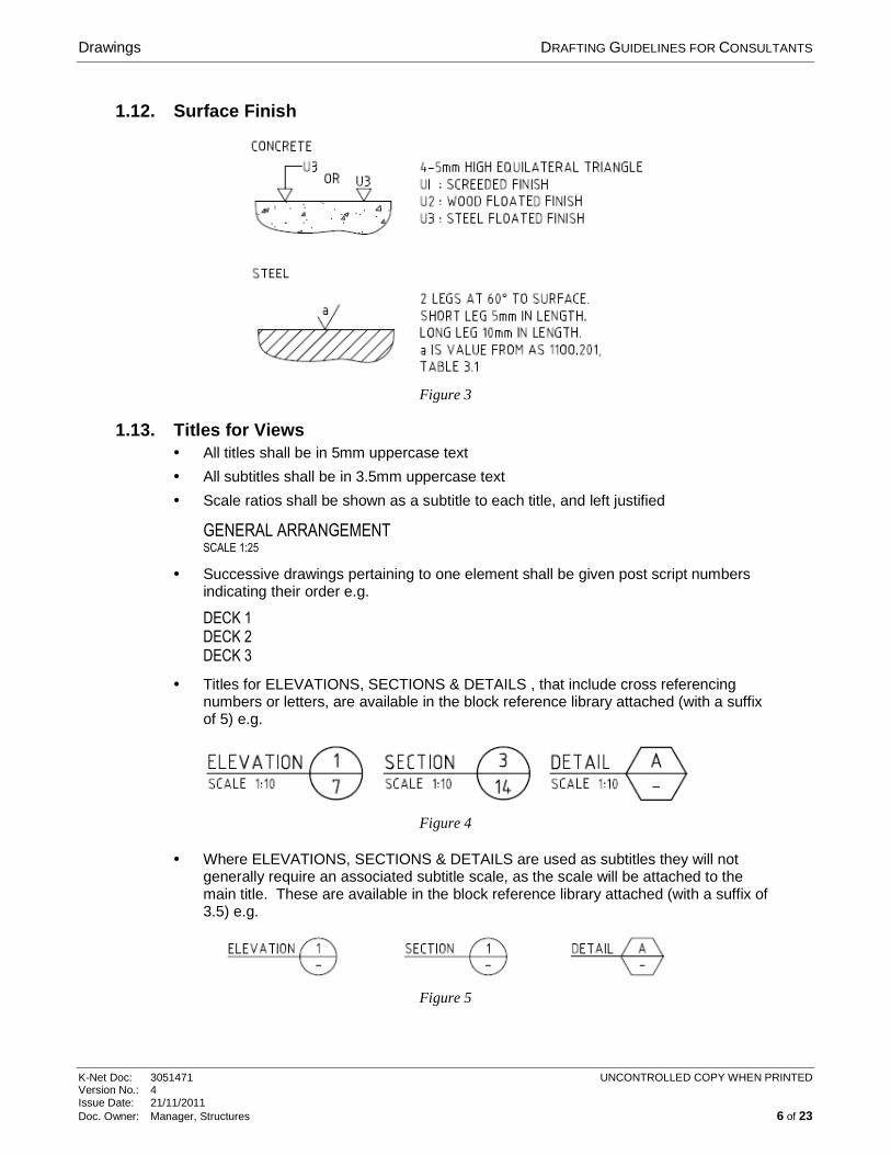
1.12. Surface Finish
Figure 3
1.13. Titles for Views • All titles shall be in 5mm uppercase text
• All subtitles shall be in 3.5mm uppercase text
• Scale ratios shall be shown as a subtitle to each title, and left justified
GENERAL ARRANGEMENT SCALE 1:25
• Successive drawings pertaining to one element shall be given post script numbers indicating their order e.g.
DECK 1
DECK 2
DECK 3
• Titles for ELEVATIONS, SECTIONS & DETAILS , that include cross referencing numbers or letters, are available in the block reference library attached (with a suffix of 5) e.g.
Figure 4
• Where ELEVATIONS, SECTIONS & DETAILS are used as subtitles they will not generally require an associated subtitle scale, as the scale will be attached to the main title. These are available in the block reference library attached (with a suffix of 3.5) e.g.
Figure 5
Drawings DRAFTING GUIDELINES FOR CONSULTANTS
K-Net Doc: 3051471 UNCONTROLLED COPY WHEN PRINTED Version No.: 4 Issue Date: 21/11/2011 Doc. Owner: Manager, Structures 7 of 23
Figure 6
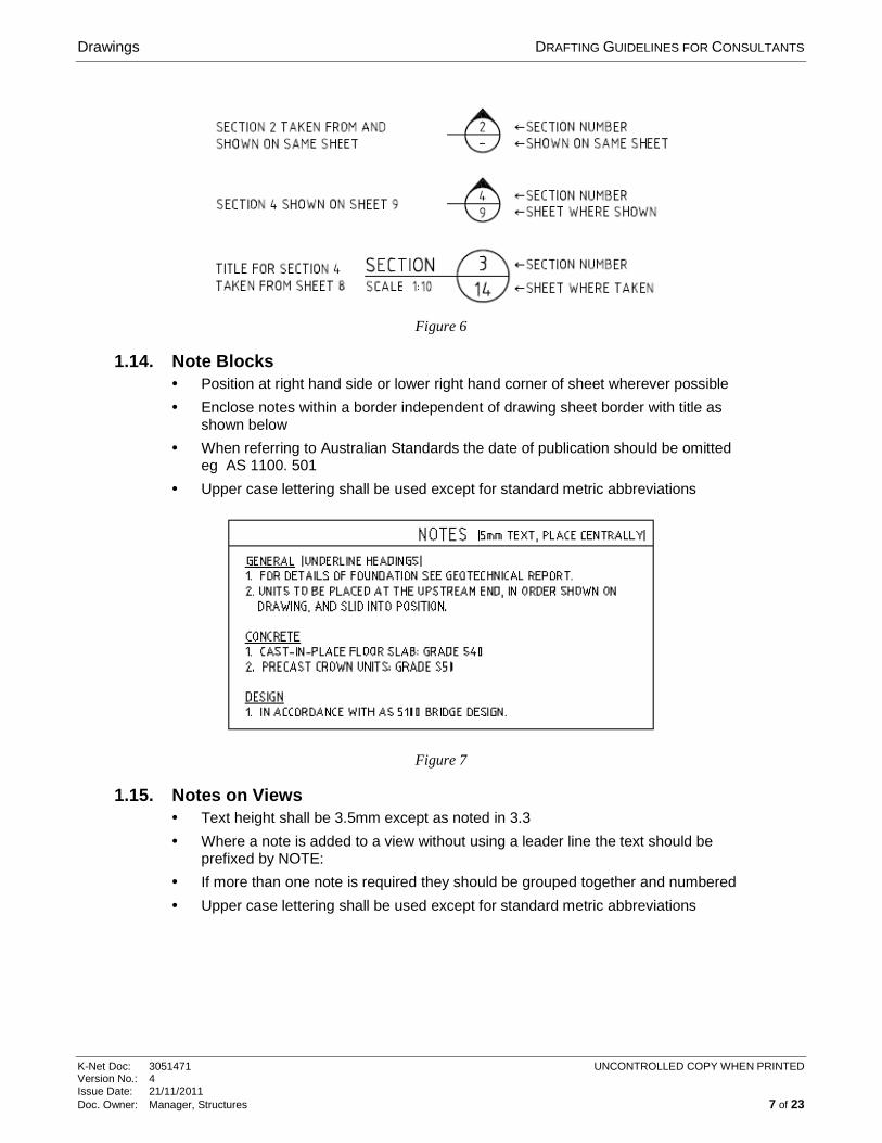
1.14. Note Blocks • Position at right hand side or lower right hand corner of sheet wherever possible
• Enclose notes within a border independent of drawing sheet border with title as shown below
• When referring to Australian Standards the date of publication should be omitted eg AS 1100. 501
• Upper case lettering shall be used except for standard metric abbreviations
Figure 7
1.15. Notes on Views • Text height shall be 3.5mm except as noted in 3.3
• Where a note is added to a view without using a leader line the text should be prefixed by NOTE:
• If more than one note is required they should be grouped together and numbered
• Upper case lettering shall be used except for standard metric abbreviations
Drawings DRAFTING GUIDELINES FOR CONSULTANTS
K-Net Doc: 3051471 UNCONTROLLED COPY WHEN PRINTED Version No.: 4 Issue Date: 21/11/2011 Doc. Owner: Manager, Structures 8 of 23
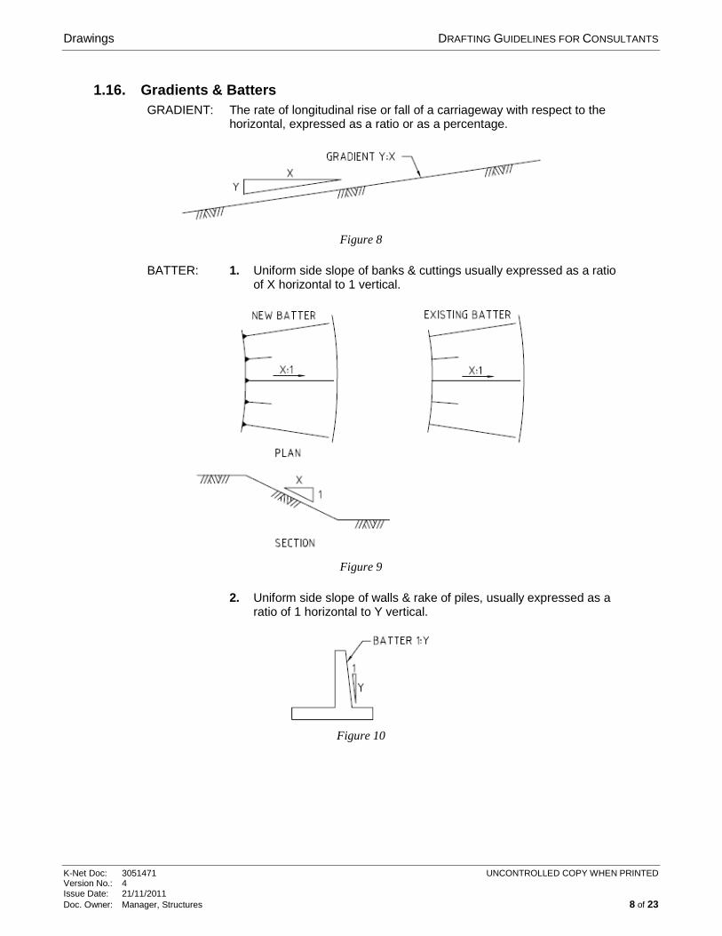
1.16. Gradients & Batters GRADIENT: The rate of longitudinal rise or fall of a carriageway with respect to the
horizontal, expressed as a ratio or as a percentage.
Figure 8
BATTER: 1. Uniform side slope of banks & cuttings usually expressed as a ratio of X horizontal to 1 vertical.
Figure 9
2. Uniform side slope of walls & rake of piles, usually expressed as a ratio of 1 horizontal to Y vertical.
Figure 10
Reinforced Concrete Detailing DRAFTING GUIDELINES FOR CONSULTANTS
K-Net Doc: 3051471 UNCONTROLLED COPY WHEN PRINTED Version No.: 4 Issue Date: 21/11/2011 Doc. Owner: Manager, Structures 9 of 23
2. REINFORCED CONCRETE DETAILING
2.1. Introduction Reinforcement shall be shown as a single thick line unless it misrepresents the shape or position of the bar. In this case reinforcement may be shown with two medium thickness lines drawn to scale in their exact position.
2.2. Standard Cover Depths Local suppliers advise that the following bar spacer sizes are available. Accordingly we should detail cover dimensions on drawings to reflect these sizes:
25mm 32mm 40mm 50mm 65mm 75mm 80mm
2.3. Minimum Spacing of Parallel Bars To avoid adjacent bars (drawn at 0.5mm lineweight) merging into one thick line a minimum gap between bar centrelines of 1mm (after scaling) is required i.e.
• At 1:10 scale minimum gap = 10mm on drawing
• At 1:20 scale minimum gap = 20mm on drawing
• Etc
2.4. Reinforcing Bar Sections Relative to Longitudinal Bars To place sectioned bars in the optimum position relative to longitudinal bars the REO block should be inserted at an offset distance of 1mm after scaling i.e.
• At 1:10 scale offset = 10mm on drawing
• At 1:20 scale offset = 20mm on drawing
• Etc
As an alternative to the REO block with an offset, use the REOREF block which has a built-in scale related offset.
Both bar section blocks are available in the block reference library attached where you should select the block with the appropriate scale.
Reinforced Concrete Detailing DRAFTING GUIDELINES FOR CONSULTANTS
K-Net Doc: 3051471 UNCONTROLLED COPY WHEN PRINTED Version No.: 4 Issue Date: 21/11/2011 Doc. Owner: Manager, Structures 10 of 23
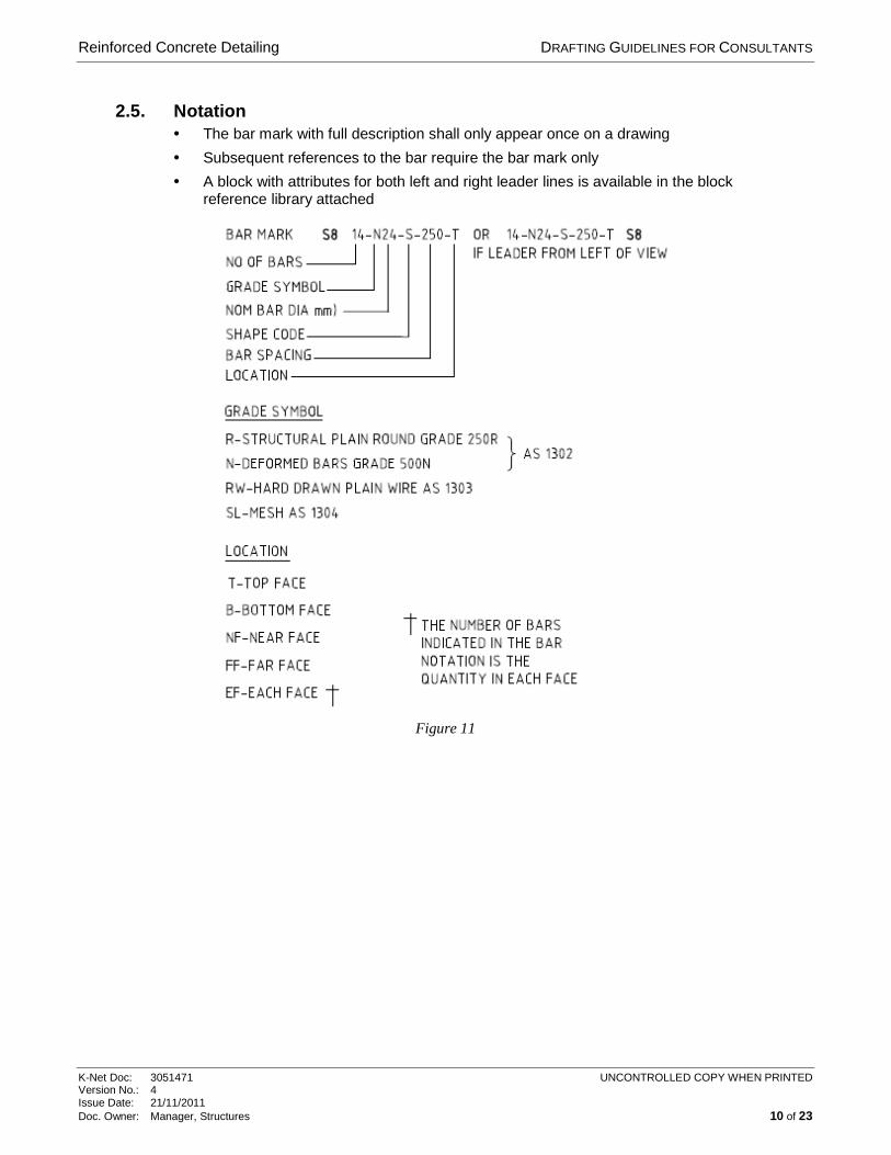
2.5. Notation • The bar mark with full description shall only appear once on a drawing
• Subsequent references to the bar require the bar mark only
• A block with attributes for both left and right leader lines is available in the block reference library attached
Figure 11
Reinforced Concrete Detailing DRAFTING GUIDELINES FOR CONSULTANTS
K-Net Doc: 3051471 UNCONTROLLED COPY WHEN PRINTED Version No.: 4 Issue Date: 21/11/2011 Doc. Owner: Manager, Structures 11 of 23
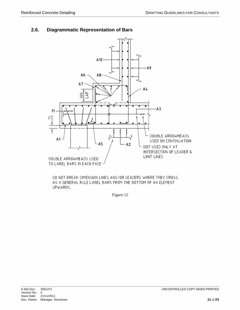
2.6. Diagrammatic Representation of Bars
Figure 12
Reinforced Concrete Detailing DRAFTING GUIDELINES FOR CONSULTANTS
K-Net Doc: 3051471 UNCONTROLLED COPY WHEN PRINTED Version No.: 4 Issue Date: 21/11/2011 Doc. Owner: Manager, Structures 12 of 23
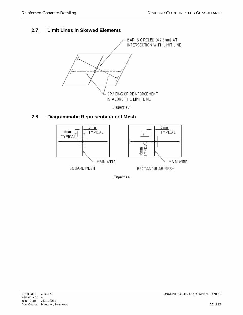
2.7. Limit Lines in Skewed Elements
Figure 13
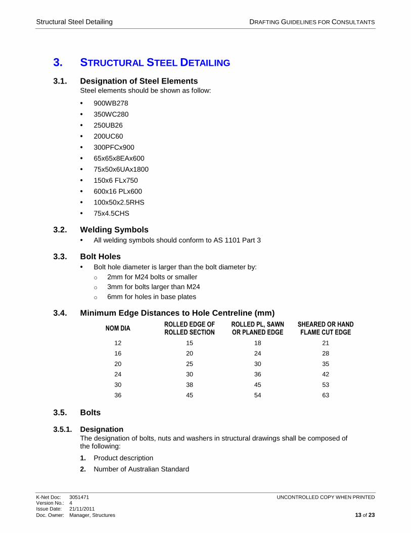
2.8. Diagrammatic Representation of Mesh
Figure 14
Structural Steel Detailing DRAFTING GUIDELINES FOR CONSULTANTS
K-Net Doc: 3051471 UNCONTROLLED COPY WHEN PRINTED Version No.: 4 Issue Date: 21/11/2011 Doc. Owner: Manager, Structures 13 of 23
3. STRUCTURAL STEEL DETAILING
3.1. Designation of Steel Elements Steel elements should be shown as follow:
• 900WB278
• 350WC280
• 250UB26
• 200UC60
• 300PFCx900
• 65x65x8EAx600
• 75x50x6UAx1800
• 150x6 FLx750
• 600x16 PLx600
• 100x50x2.5RHS
• 75x4.5CHS
3.2. Welding Symbols • All welding symbols should conform to AS 1101 Part 3
3.3. Bolt Holes • Bolt hole diameter is larger than the bolt diameter by:
o 2mm for M24 bolts or smaller o 3mm for bolts larger than M24 o 6mm for holes in base plates
3.4. Minimum Edge Distances to Hole Centreline (mm)
NOM DIA ROLLED EDGE OF ROLLED SECTION
ROLLED PL, SAWN OR PLANED EDGE
SHEARED OR HAND FLAME CUT EDGE
12 15 18 21
16 20 24 28
20 25 30 35
24 30 36 42
30 38 45 53
36 45 54 63
3.5. Bolts
3.5.1. Designation The designation of bolts, nuts and washers in structural drawings shall be composed of the following:
1. Product description
2. Number of Australian Standard
Structural Steel Detailing DRAFTING GUIDELINES FOR CONSULTANTS
K-Net Doc: 3051471 UNCONTROLLED COPY WHEN PRINTED Version No.: 4 Issue Date: 21/11/2011 Doc. Owner: Manager, Structures 14 of 23
3. The letter M indicating that the product has a metric course pitch thread followed by the thread diameter (in mm)
4. The nominal length (in mm)
5. The property class symbol or material if other than steel
6. The bolting procedure describing the method of tensioning the bolts (only necessary for high strength structural bolts)
a) S snug tightened b) TF fully tensioned, friction type c) TB fully tensioned, bearing type
7. The coating, where applicable, in accordance with the appropriate Australian Standard
3.6. Annotation on Drawing Two metric thread bolts with 16mm thread diameter of nominal length 50mm and property class 8.8 (high strength structural) snug tightened shall be shown thus: 2 BOLTS, M16x50 8.8/S.
Five metric thread bolts with 20mm thread diameter of nominal length 100mm and property class 4.6 (commercial) to be hot dip galvanized shall be shown thus: 5 BOLTS, M20x100 4.6 (GALVANIZED).
Two metric thread bolts with 16mm thread diameter of nominal length 100mm in stainless steel shall be shown thus: 2 BOLTS, M20x100 STAINLESS STEEL.
When all bolts on drawing are same property class and/or coating (if required) the relevant information can be omitted from the annotation and addressed in the Notes e.g. 5 BOLTS, M20x100.
3.7. Details in Notes The Australian Standards defining all bolts, nuts & washers (and any coating where applicable) used on the drawing shall be listed in the Notes e.g.
ALL BOLTS, NUTS AND WASHERS TO AS/NZS 1111, 1112 AND 1237 RESPECTIVELY. ALL BOLTS, NUTS AND WASHERS TO BE HOT DIP GALVANIZED IN ACCORDANCE WITH AS/NZS 4680 AND AS 1214.
Locality Plans DRAFTING GUIDELINES FOR CONSULTANTS
K-Net Doc: 3051471 UNCONTROLLED COPY WHEN PRINTED Version No.: 4 Issue Date: 21/11/2011 Doc. Owner: Manager, Structures 15 of 23
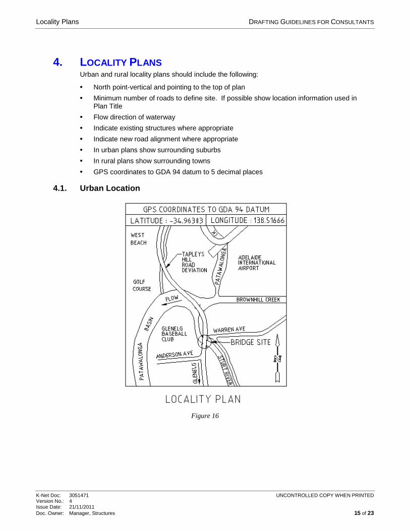
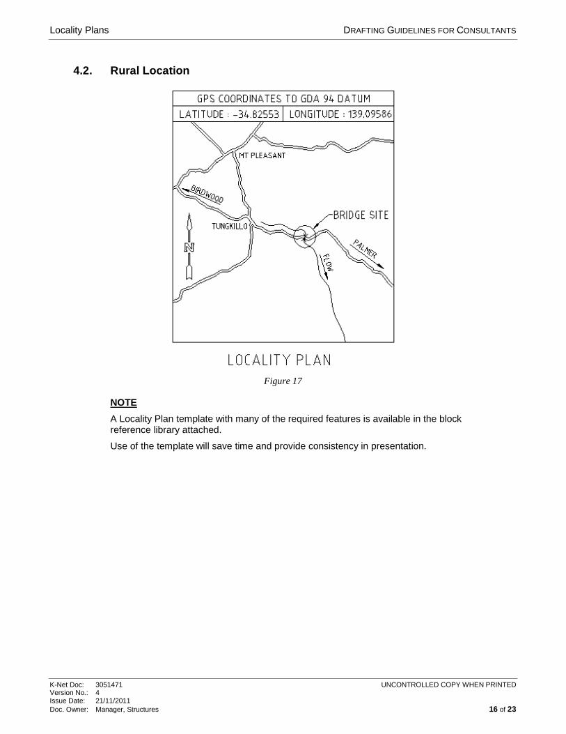
4. LOCALITY PLANS Urban and rural locality plans should include the following:
• North point-vertical and pointing to the top of plan
• Minimum number of roads to define site. If possible show location information used in Plan Title
• Flow direction of waterway
• Indicate existing structures where appropriate
• Indicate new road alignment where appropriate
• In urban plans show surrounding suburbs
• In rural plans show surrounding towns
• GPS coordinates to GDA 94 datum to 5 decimal places
4.1. Urban Location
Figure 16
Locality Plans DRAFTING GUIDELINES FOR CONSULTANTS
K-Net Doc: 3051471 UNCONTROLLED COPY WHEN PRINTED Version No.: 4 Issue Date: 21/11/2011 Doc. Owner: Manager, Structures 16 of 23
4.2. Rural Location
Figure 17
NOTE
A Locality Plan template with many of the required features is available in the block reference library attached.
Use of the template will save time and provide consistency in presentation.
Cad Information DRAFTING GUIDELINES FOR CONSULTANTS
K-Net Doc: 3051471 UNCONTROLLED COPY WHEN PRINTED Version No.: 4 Issue Date: 21/11/2011 Doc. Owner: Manager, Structures 17 of 23
5. CAD INFORMATION
5.1. Template The template ‘A Structural 2011 - DPTI.dwt’ is attached and shall be used for all Structural drawings prepared for the Department.
This will set up all the layers, dimensions and text styles.
Note: The A1 drawing frame is included in the template and appears automatically in “layout space”.
5.2. Drawing File Presentation All file names used within the Structures & Geotechnical Groups shall be as shown with the drawing number followed by the sheet number in both dwg and dwf format as shown below e.g.
7156_SHT_01.dwg
7156_SHT_02.dwf
Contractors and consultants engaged in work for the Section shall follow this convention.
When files named in this manner have been finalised copies in both formats shall be provided to Transport Services.
Note: • Dwf files to be presented on a white background • Draw in model space in mm at a scale of 1:1
5.3. Text Styles All Structural & Geotechnical drawings shall use only the following fonts:
ISOCP A proportional font to be used for all text
• All general text to be 3.5mm high with 0.35mm thickness
• All headings to be 5.0mm high with 0.50mm thickness
5.4. Dimensions • For dimension text use 3.5mm height with a 0.25mm thickness
• Arrow head used in dimensioning shall be closed filled
• Arrow size shall be 3mm
Cad Information DRAFTING GUIDELINES FOR CONSULTANTS
K-Net Doc: 3051471 UNCONTROLLED COPY WHEN PRINTED Version No.: 4 Issue Date: 21/11/2011 Doc. Owner: Manager, Structures 18 of 23
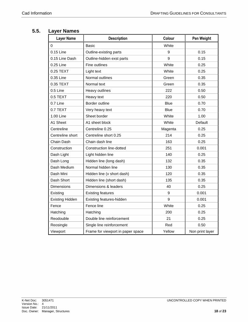
5.5. Layer Names Layer Name Description Colour Pen Weight
0 Basic White
0.15 Line Outline-existing parts 9 0.15
0.15 Line Dash Outline-hidden exst parts 9 0.15
0.25 Line Fine outlines White 0.25
0.25 TEXT Light text White 0.25
0.35 Line Normal outlines Green 0.35
0.35 TEXT Normal text Green 0.35
0.5 Line Heavy outlines 222 0.50
0.5 TEXT Heavy text 220 0.50
0.7 Line Border outline Blue 0.70
0.7 TEXT Very heavy text Blue 0.70
1.00 Line Sheet border White 1.00
A1 Sheet A1 sheet block White Default
Centreline Centreline 0.25 Magenta 0.25
Centreline short Centreline short 0.25 214 0.25
Chain Dash Chain dash line 163 0.25
Construction Construction line-dotted 251 0.001
Dash Light Light hidden line 140 0.25
Dash Long Hidden line (long dash) 132 0.35
Dash Medium Normal hidden line 130 0.35
Dash Mini Hidden line (v short dash) 120 0.35
Dash Short Hidden line (short dash) 135 0.35
Dimensions Dimensions & leaders 40 0.25
Existing Existing features 9 0.001
Existing Hidden Existing features-hidden 9 0.001
Fence Fence line White 0.25
Hatching Hatching 200 0.25
Reodouble Double line reinforcement 21 0.25
Reosingle Single line reinforcement Red 0.50
Viewport Frame for viewport in paper space Yellow Non print layer
Bridge Plaque and Recess Details Drawing DRAFTING GUIDELINES FOR CONSULTANTS
K-Net Doc: 3051471 UNCONTROLLED COPY WHEN PRINTED Version No.: 4 Issue Date: 21/11/2011 Doc. Owner: Manager, Structures 19 of 23
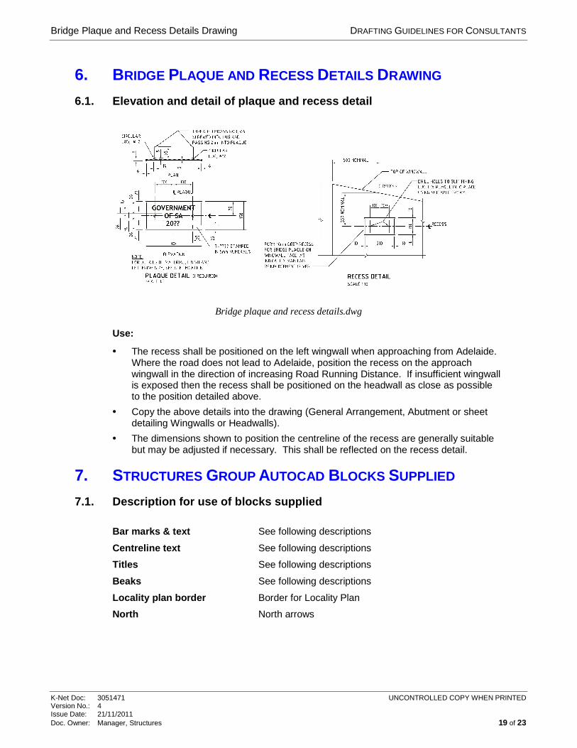
6. BRIDGE PLAQUE AND RECESS DETAILS DRAWING
6.1. Elevation and detail of plaque and recess detail
Bridge plaque and recess details.dwg
Use:
• The recess shall be positioned on the left wingwall when approaching from Adelaide. Where the road does not lead to Adelaide, position the recess on the approach wingwall in the direction of increasing Road Running Distance. If insufficient wingwall is exposed then the recess shall be positioned on the headwall as close as possible to the position detailed above.
• Copy the above details into the drawing (General Arrangement, Abutment or sheet detailing Wingwalls or Headwalls).
• The dimensions shown to position the centreline of the recess are generally suitable but may be adjusted if necessary. This shall be reflected on the recess detail.
7. STRUCTURES GROUP AUTOCAD BLOCKS SUPPLIED
7.1. Description for use of blocks supplied
Bar marks & text See following descriptions
Centreline text See following descriptions
Titles See following descriptions
Beaks See following descriptions
Locality plan border Border for Locality Plan
North North arrows
Structures Group Autocad Blocks Supplied DRAFTING GUIDELINES FOR CONSULTANTS
K-Net Doc: 3051471 UNCONTROLLED COPY WHEN PRINTED Version No.: 4 Issue Date: 21/11/2011 Doc. Owner: Manager, Structures 20 of 23
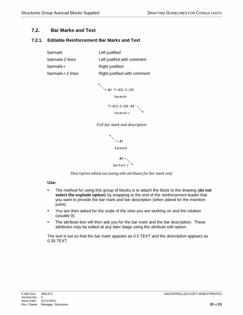
7.2. Bar Marks and Text
7.2.1. Editable Reinforcement Bar Marks and Text
barmark Left justified
barmark-2 lines Left justifed with comment
barmark-r Right justified
barmark-r-2 lines Right justified with comment
Full bar mark and description
Description edited out (using edit attribute) for bar mark only
Use:
• The method for using this group of blocks is to attach the block to the drawing (do not select the explode option) by snapping to the end of the reinforcement leader that you want to provide the bar mark and bar description (when asked for the insertion point).
• You are then asked for the scale of the view you are working on and the rotation (usually 0).
• The attribute box will then ask you for the bar mark and the bar description. These attributes may be edited at any later stage using the attribute edit option.
The text is set so that the bar mark appears as 0.5 TEXT and the description appears as 0.35 TEXT.
Structures Group Autocad Blocks Supplied DRAFTING GUIDELINES FOR CONSULTANTS
K-Net Doc: 3051471 UNCONTROLLED COPY WHEN PRINTED Version No.: 4 Issue Date: 21/11/2011 Doc. Owner: Manager, Structures 21 of 23
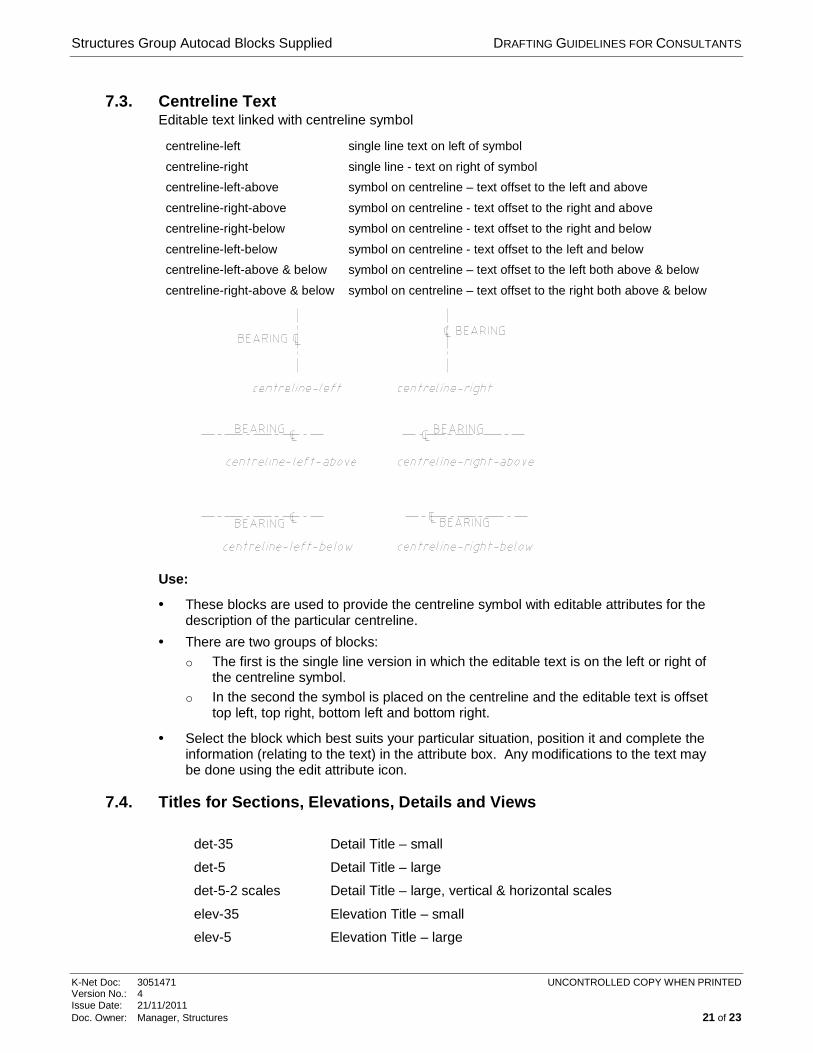
7.3. Centreline Text Editable text linked with centreline symbol
centreline-left single line text on left of symbol
centreline-right single line - text on right of symbol
centreline-left-above symbol on centreline – text offset to the left and above
centreline-right-above symbol on centreline - text offset to the right and above
centreline-right-below symbol on centreline - text offset to the right and below
centreline-left-below symbol on centreline - text offset to the left and below
centreline-left-above & below symbol on centreline – text offset to the left both above & below
centreline-right-above & below symbol on centreline – text offset to the right both above & below
Use:
• These blocks are used to provide the centreline symbol with editable attributes for the description of the particular centreline.
• There are two groups of blocks: o The first is the single line version in which the editable text is on the left or right of
the centreline symbol. o In the second the symbol is placed on the centreline and the editable text is offset
top left, top right, bottom left and bottom right.
• Select the block which best suits your particular situation, position it and complete the information (relating to the text) in the attribute box. Any modifications to the text may be done using the edit attribute icon.
7.4. Titles for Sections, Elevations, Details and Views
det-35 Detail Title – small
det-5 Detail Title – large
det-5-2 scales Detail Title – large, vertical & horizontal scales
elev-35 Elevation Title – small
elev-5 Elevation Title – large
Structures Group Autocad Blocks Supplied DRAFTING GUIDELINES FOR CONSULTANTS
K-Net Doc: 3051471 UNCONTROLLED COPY WHEN PRINTED Version No.: 4 Issue Date: 21/11/2011 Doc. Owner: Manager, Structures 22 of 23
elev-5-2 scales Elevation Title – large, vertical & horizontal scales
Elevation Elevation Title – large, no cross reference
Plan Plan Title – large, no cross reference
sec-35 Section Title – small
sec-5 Section Title – large
sec-5-2 scales Section Title – large, vertical & horizontal scales
view-35 View Title – small
view-5 View Title – large
view-5-2 scales View Title – large, vertical & horizontal scales
Use:
• All these titles are inserted into the drawing and not exploded. Use the scale of the particular section view etc. as the multiplication factor. Answer the prompts for scale, section number etc.
7.5. Beaks
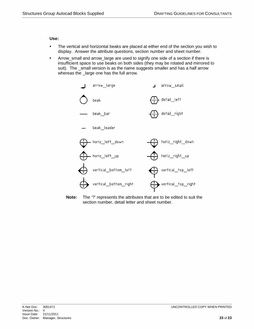
7.5.1. Section beaks and detail hexagons
Type Description
arrow_small plain section arrow (no beak) small version with half arrow
arrow_large plain section arrow (no beak) larger version with half arrow
Beak plain circle with beak that can be rotated to suit direction of section - no attributes
beak_leader plain leader that can be rotated to suit section and is attached to plain beak
beak_bar horizontal bar that is attached to plain beak
detail_left detail hexagon on left of leader with attributes
detail_right detail hexagon on right of leader with attributes
horiz_left_down horizontal beak on left hand side looking down, with attributes
horiz_left_up horizontal beak on left hand side looking up, with attributes
horiz_right_down horizontal beak on right hand side looking down, with attributes
horiz_right_up horizontal beak on right hand side looking up, with attributes
vertical_bottom_left vertical beak on bottom looking towards the left, with attributes
vertical_bottom_right vertical beak on bottom looking towards right, with attributes
vertical_top_left vertical beak on top looking towards the left, with attributes
vertical_top_right vertical beak on top looking towards the right, with attributes
Structures Group Autocad Blocks Supplied DRAFTING GUIDELINES FOR CONSULTANTS
K-Net Doc: 3051471 UNCONTROLLED COPY WHEN PRINTED Version No.: 4 Issue Date: 21/11/2011 Doc. Owner: Manager, Structures 23 of 23
Use:
• The vertical and horizontal beaks are placed at either end of the section you wish to display. Answer the attribute questions, section number and sheet number.
• Arrow_small and arrow_large are used to signify one side of a section if there is insufficient space to use beaks on both sides (they may be rotated and mirrored to suit). The _small version is as the name suggests smaller and has a half arrow whereas the _large one has the full arrow.
Note: The ‘?’ represents the attributes that are to be edited to suit the
section number, detail letter and sheet number.


![[AISC] Detailing for Steel Construction (Bookos.org)](https://img.pdfslide.us/doc/110x75/55cf91a0550346f57b8f0f85/aisc-detailing-for-steel-construction-bookosorg.jpg)